EP3043053A1 - System and method for detecting reciprocating device abnormalities utilizing standard quality control techniques - Google Patents
System and method for detecting reciprocating device abnormalities utilizing standard quality control techniques Download PDFInfo
- Publication number
- EP3043053A1 EP3043053A1 EP16150238.0A EP16150238A EP3043053A1 EP 3043053 A1 EP3043053 A1 EP 3043053A1 EP 16150238 A EP16150238 A EP 16150238A EP 3043053 A1 EP3043053 A1 EP 3043053A1
- Authority
- EP
- European Patent Office
- Prior art keywords
- signal
- reciprocating device
- controller
- engine
- spectral
- Prior art date
- Legal status (The legal status is an assumption and is not a legal conclusion. Google has not performed a legal analysis and makes no representation as to the accuracy of the status listed.)
- Granted
Links
Images


Classifications
-
- F—MECHANICAL ENGINEERING; LIGHTING; HEATING; WEAPONS; BLASTING
- F02—COMBUSTION ENGINES; HOT-GAS OR COMBUSTION-PRODUCT ENGINE PLANTS
- F02D—CONTROLLING COMBUSTION ENGINES
- F02D35/00—Controlling engines, dependent on conditions exterior or interior to engines, not otherwise provided for
- F02D35/02—Controlling engines, dependent on conditions exterior or interior to engines, not otherwise provided for on interior conditions
- F02D35/027—Controlling engines, dependent on conditions exterior or interior to engines, not otherwise provided for on interior conditions using knock sensors
-
- F—MECHANICAL ENGINEERING; LIGHTING; HEATING; WEAPONS; BLASTING
- F02—COMBUSTION ENGINES; HOT-GAS OR COMBUSTION-PRODUCT ENGINE PLANTS
- F02D—CONTROLLING COMBUSTION ENGINES
- F02D41/00—Electrical control of supply of combustible mixture or its constituents
- F02D41/22—Safety or indicating devices for abnormal conditions
-
- G—PHYSICS
- G01—MEASURING; TESTING
- G01L—MEASURING FORCE, STRESS, TORQUE, WORK, MECHANICAL POWER, MECHANICAL EFFICIENCY, OR FLUID PRESSURE
- G01L23/00—Devices or apparatus for measuring or indicating or recording rapid changes, such as oscillations, in the pressure of steam, gas, or liquid; Indicators for determining work or energy of steam, internal-combustion, or other fluid-pressure engines from the condition of the working fluid
- G01L23/22—Devices or apparatus for measuring or indicating or recording rapid changes, such as oscillations, in the pressure of steam, gas, or liquid; Indicators for determining work or energy of steam, internal-combustion, or other fluid-pressure engines from the condition of the working fluid for detecting or indicating knocks in internal-combustion engines; Units comprising pressure-sensitive members combined with ignitors for firing internal-combustion engines
- G01L23/221—Devices or apparatus for measuring or indicating or recording rapid changes, such as oscillations, in the pressure of steam, gas, or liquid; Indicators for determining work or energy of steam, internal-combustion, or other fluid-pressure engines from the condition of the working fluid for detecting or indicating knocks in internal-combustion engines; Units comprising pressure-sensitive members combined with ignitors for firing internal-combustion engines for detecting or indicating knocks in internal combustion engines
-
- G—PHYSICS
- G01—MEASURING; TESTING
- G01M—TESTING STATIC OR DYNAMIC BALANCE OF MACHINES OR STRUCTURES; TESTING OF STRUCTURES OR APPARATUS, NOT OTHERWISE PROVIDED FOR
- G01M15/00—Testing of engines
- G01M15/04—Testing internal-combustion engines
- G01M15/042—Testing internal-combustion engines by monitoring a single specific parameter not covered by groups G01M15/06 - G01M15/12
-
- F—MECHANICAL ENGINEERING; LIGHTING; HEATING; WEAPONS; BLASTING
- F02—COMBUSTION ENGINES; HOT-GAS OR COMBUSTION-PRODUCT ENGINE PLANTS
- F02D—CONTROLLING COMBUSTION ENGINES
- F02D41/00—Electrical control of supply of combustible mixture or its constituents
- F02D41/24—Electrical control of supply of combustible mixture or its constituents characterised by the use of digital means
- F02D41/26—Electrical control of supply of combustible mixture or its constituents characterised by the use of digital means using computer, e.g. microprocessor
- F02D41/28—Interface circuits
- F02D2041/286—Interface circuits comprising means for signal processing
- F02D2041/288—Interface circuits comprising means for signal processing for performing a transformation into the frequency domain, e.g. Fourier transformation
-
- Y—GENERAL TAGGING OF NEW TECHNOLOGICAL DEVELOPMENTS; GENERAL TAGGING OF CROSS-SECTIONAL TECHNOLOGIES SPANNING OVER SEVERAL SECTIONS OF THE IPC; TECHNICAL SUBJECTS COVERED BY FORMER USPC CROSS-REFERENCE ART COLLECTIONS [XRACs] AND DIGESTS
- Y02—TECHNOLOGIES OR APPLICATIONS FOR MITIGATION OR ADAPTATION AGAINST CLIMATE CHANGE
- Y02T—CLIMATE CHANGE MITIGATION TECHNOLOGIES RELATED TO TRANSPORTATION
- Y02T10/00—Road transport of goods or passengers
- Y02T10/10—Internal combustion engine [ICE] based vehicles
- Y02T10/30—Use of alternative fuels, e.g. biofuels
-
- Y—GENERAL TAGGING OF NEW TECHNOLOGICAL DEVELOPMENTS; GENERAL TAGGING OF CROSS-SECTIONAL TECHNOLOGIES SPANNING OVER SEVERAL SECTIONS OF THE IPC; TECHNICAL SUBJECTS COVERED BY FORMER USPC CROSS-REFERENCE ART COLLECTIONS [XRACs] AND DIGESTS
- Y02—TECHNOLOGIES OR APPLICATIONS FOR MITIGATION OR ADAPTATION AGAINST CLIMATE CHANGE
- Y02T—CLIMATE CHANGE MITIGATION TECHNOLOGIES RELATED TO TRANSPORTATION
- Y02T10/00—Road transport of goods or passengers
- Y02T10/10—Internal combustion engine [ICE] based vehicles
- Y02T10/40—Engine management systems
Definitions
- the subject matter disclosed herein relates to knock sensors, and more specifically, to utilizing knock sensors mounted to large, multi-cylinder reciprocating devices (e.g., combustion engine, compressors, etc.) in conjunction with standard quality control techniques to detect reciprocating device abnormalities.
- large, multi-cylinder reciprocating devices e.g., combustion engine, compressors, etc.
- Combustion engines typically combust a carbonaceous fuel, such as natural gas, gasoline, diesel, and the like, and use the corresponding expansion of high temperature and pressure gases to apply a force to certain components of the engine, e.g., piston disposed in a cylinder, to move the components over a distance.
- a carbonaceous fuel such as natural gas, gasoline, diesel, and the like
- Each cylinder may include one or more valves that open and close correlative with combustion of the carbonaceous fuel.
- an intake valve may direct an oxidizer such as air into the cylinder, which is then mixed with fuel and combusted.
- Combustion fluids e.g., hot gases, may then be directed to exit the cylinder via an exhaust valve.
- the carbonaceous fuel is transformed into mechanical motion, useful in driving a load.
- the load may be a generator that produces electric power.
- combustion engines may experience various noises, mechanical faults, or changes in conditions that may be difficult to detect and/or predict.
- a system includes a controller configured to receive a signal acquired by the at least one knock sensor coupled to a reciprocating device, to sample the received signal, to analyze the sampled signal, and to utilize standard quality control (SQC) techniques to perform real-time diagnostics on the reciprocating device based on the analyzed signal.
- SQC standard quality control
- a system in accordance with a second aspect, includes a method for performing real-time diagnostics on a reciprocating device.
- the method includes utilizing a controller communicatively coupled to the reciprocating device for receiving a signal from at least one knock sensor coupled to the reciprocating device, sampling the received signal, analyzing the sampled signal, and utilizing SQC techniques to perform real-time diagnostics on the reciprocating device based on the analyzed signal.
- a system in accordance with a third aspect, includes a method for performing real-time diagnostics on a reciprocating device.
- the method includes utilizing a controller communicatively coupled to the reciprocating device for sampling a signal received from at least one knock sensor coupled to the reciprocating device, applying a temporal filter to the sampled signal to generate a temporal filtered signal, and applying a fast Fourier transform to the temporal filtered signal to generate a Fourier transformed signal.
- the method also includes utilizing the controller for generating a power spectral density from the Fourier transformed signal, and utilizing SQC techniques to perform real-time diagnostics on the reciprocating device based on the power spectral density.
- combustion engines may experience various noises due to mechanical faults or changes in conditions that may be difficult to detect and/or predict.
- Knock sensors may be utilized to monitor a combustion engine. Occasionally, the knock sensor system records a noise, such as an abnormal or undesired noise. Rather than ignore and discard the unidentifiable noises, it may be advantageous to monitor the noise overtime to identify any potential faults (e.g., engine faults) or abnormal conditions. These faults or conditions may include normal wearing maintenance items and/or abnormal component failures. It may also be advantageous to utilize SQC techniques (e.g., SQC charting techniques) for both diagnostics and advanced prognostics (e.g., to monitor for non-Gaussian behavior).
- SQC techniques e.g., SQC charting techniques
- FIG. 1 illustrates a block diagram of an embodiment of a portion of an engine driven power generation system 8.
- the system 8 includes an engine 10 (e.g., a reciprocating internal combustion engine) having one or more combustion chambers 12 (e.g., 1, 2, 3, 4, 5, 6, 7, 8, 10, 12, 14, 16, 18, 20, or more combustion chambers 12).
- An air supply 14 is configured to provide a pressurized oxidant 16, such as air, oxygen, oxygen-enriched air, oxygen-reduced air, or any combination thereof, to each combustion chamber 12.
- the combustion chamber 12 is also configured to receive a fuel 18 (e.g., a liquid and/or gaseous fuel) from a fuel supply 19, and a fuel-air mixture ignites and combusts within each combustion chamber 12.
- a fuel 18 e.g., a liquid and/or gaseous fuel
- the hot pressurized combustion gases cause a piston 20 adjacent to each combustion chamber 12 to move linearly within a cylinder 26 and convert pressure exerted by the gases into a rotating motion, which causes a shaft 22 to rotate.
- the shaft 22 may be coupled to a load 24, which is powered via rotation of the shaft 22.
- the load 24 may be any suitable device that may generate power via the rotational output of the system 10, such as an electrical generator.
- the fuel 18 may be any suitable gaseous fuel, such as natural gas, associated petroleum gas, propane, biogas, sewage gas, landfill gas, coal mine gas, for example.
- the system 8 disclosed herein may be adapted for use in stationary applications (e.g., in industrial power generating engines) or in mobile applications (e.g., in cars or aircraft).
- the engine 10 may be a two-stroke engine, three-stroke engine, four-stroke engine, five-stroke engine, or six-stroke engine.
- the engine 10 may also include any number of combustion chambers 12, pistons 20, and associated cylinders (e.g., 1-24).
- the system 8 may include a large-scale industrial reciprocating engine having 4, 6, 8, 10, 16, 24 or more pistons 20 reciprocating in cylinders.
- the cylinders and/or the pistons 20 may have a diameter of between approximately 13.5 - 34 centimeters (cm).
- the cylinders and/or the pistons 20 may have a diameter of between approximately 10-40 cm, 15-25 cm, or about 15 cm.
- the system 10 may generate power ranging from 10 kW to 10 MW.
- the engine 10 may operate at less than approximately 1800 revolutions per minute (RPM).
- the engine 10 may operate at less than approximately 2000 RPM, 1900 RPM, 1700 RPM, 1600 RPM, 1500 RPM, 1400 RPM, 1300 RPM, 1200 RPM, 1000 RPM, 900 RPM, or 750 RPM.
- the engine 10 may operate between approximately 750-2000 RPM, 900-1800 RPM, or 1000-1600 RPM.
- the engine 10 may operate at approximately 1800 RPM, 1500 RPM, 1200 RPM, 1000 RPM, or 900 RPM.
- Exemplary engines 10 may include General Electric Company's Jenbacher Engines (e.g., Jenbacher Type 2, Type 3, Type 4, Type 6 or J920 FleXtra) or Waukesha Engines (e.g., Waukesha VGF, VHP, APG, 275GL), for example.
- the engine driven power generation system 8 may include one or more knock sensors 23 suitable for detecting engine “knock.”
- the knock sensor 23 may sense vibrations caused by the engine, such as vibration due to detonation, pre-ignition, and or pinging.
- the engine driven power generation system may include other sensors 27 (e.g., one or more temperature transducers) to detect other operating conditions (e.g., temperature (e.g., global temperature and/or temperature gradient) of a medium (e.g., cast iron) that the one or more knock sensors 23 are coupled to).
- the knock sensor 23 is shown communicatively coupled to an engine control unit (ECU) 25.
- ECU engine control unit
- signals from the knock sensor 23 are communicated to the ECU 25 to determine if knocking conditions (e.g., pinging) exist.
- the ECU 25 may then adjust certain engine 10 parameters to ameliorate or eliminate the knocking conditions.
- the ECU 25 may adjust ignition timing and/or adjust boost pressure to eliminate the knocking.
- the knock sensor 23 may additionally derive that certain vibrations should be further analyzed and categorized to monitor, for example, potentially undesired engine conditions.
- FIG. 2 is a side cross-sectional view of an embodiment of a piston assembly 25 having a piston 20 disposed within a cylinder 26 (e.g., an engine cylinder) of the reciprocating engine 10.
- the cylinder 26 has an inner annular wall 28 defining a cylindrical cavity 30 (e.g., bore).
- the piston 20 may be defined by an axial axis or direction 34, a radial axis or direction 36, and a circumferential axis or direction 38.
- the piston 20 includes a top portion 40 (e.g., a top land).
- the top portion 40 generally blocks the fuel 18 and the air 16, or a fuel-air mixture 32, from escaping from the combustion chamber 12 during reciprocating motion of the piston 20.
- the piston 20 is attached to a crankshaft 54 via a connecting rod 56 and a pin 58.
- the crankshaft 54 translates the reciprocating linear motion of the piston 24 into a rotating motion.
- the crankshaft 54 rotates to power the load 24 (shown in FIG. 1 ), as discussed above.
- the combustion chamber 12 is positioned adjacent to the top land 40 of the piston 24.
- a fuel injector 60 provides the fuel 18 to the combustion chamber 12, and an intake valve 62 controls the delivery of air 16 to the combustion chamber 12.
- An exhaust valve 64 controls discharge of exhaust from the engine 10.
- any suitable elements and/or techniques for providing fuel 18 and air 16 to the combustion chamber 12 and/or for discharging exhaust may be utilized, and in some embodiments, no fuel injection is used.
- combustion of the fuel 18 with the air 16 in the combustion chamber 12 cause the piston 20 to move in a reciprocating manner (e.g., back and forth) in the axial direction 34 within the cavity 30 of the cylinder 26.
- crankshaft 54 rotates one half of a revolution.
- engine 10 embodiments may include two-stroke engines, three-stroke engines, four-stroke engines, five-stroke engine, six-stroke engines, or more.
- a sequence including an intake process, a compression process, a power process, and an exhaust process typically occurs.
- the intake process enables a combustible mixture, such as fuel and air, to be pulled into the cylinder 26, thus the intake valve 62 is open and the exhaust valve 64 is closed.
- the compression process compresses the combustible mixture into a smaller space, so both the intake valve 62 and the exhaust valve 64 are closed.
- the power process ignites the compressed fuel-air mixture, which may include a spark ignition through a spark plug system, and/or a compression ignition through compression heat.
- the resulting pressure from combustion then forces the piston 20 to BDC.
- the exhaust process typically returns the piston 20 to TDC while keeping the exhaust valve 64 open. The exhaust process thus expels the spent fuel-air mixture through the exhaust valve 64.
- more than one intake valve 62 and exhaust valve 64 may be used per cylinder 26.
- the depicted engine 10 also includes a crankshaft sensor 66, the knock sensor 23, and the engine control unit (ECU) 25, which includes a processor 72 and memory 74.
- the crankshaft sensor 66 senses the position and/or rotational speed of the crankshaft 54. Accordingly, a crank angle or crank timing information may be derived. That is, when monitoring combustion engines, timing is frequently expressed in terms of crankshaft 54 angle. For example, a full cycle of a four stroke engine 10 may be measured as a 720° cycle.
- the knock sensor 23 may be a Piezo-electric accelerometer, a microelectromechanical system (MEMS) sensor, a Hall effect sensor, a magnetorestrictive sensor, and/or any other sensor designed to sense vibration, acceleration, sound, and/or movement.
- MEMS microelectromechanical system
- sensor 23 may not be a knock sensor, but any sensor that may sense vibration, pressure, acceleration, deflection, or movement.
- the knock sensor 23 may be capable of detecting signatures even when mounted on the exterior of the cylinder 26. However, the knock sensor 23 may be disposed at various locations in or about the cylinder 26. Additionally, in some embodiments, a single knock sensor 23 may be shared, for example, with one or more adjacent cylinders 26. In other embodiments, each cylinder 26 may include one or more knock sensors 23 (e.g., one or more arrays of knock sensors 23 arranged along one or more planes through the engine 10). The crankshaft sensor 66 and the knock sensor 23 are shown in electronic communication with the engine control unit (ECU) 25. The ECU 25 includes the processor 72 and the memory 74 (e.g., a machine-readable medium).
- the ECU 25 includes the processor 72 and the memory 74 (e.g., a machine-readable medium).
- the memory 74 may store non-transitory code or computer instructions that may be executed by the processor 72.
- the ECU 25 monitors and controls and operation of the engine 10, for example, by adjusting combustion timing, valve 62, 64, timing, adjusting the delivery of fuel and oxidant (e.g., air), and so on.
- fuel and oxidant e.g., air
- the techniques described herein may use the ECU 25 to receive, acquire, or sample data (e.g., noise signals) from the one or more crankshaft sensors 66 and/or the one or more knock sensors 23.
- data from the sensors e.g., knock sensors and/or crankshaft sensors 66
- the noise signals utilized to detect and/or locate coincident noises may be received solely from the one or more knock sensors 23.
- the noise signals may be utilized to detect and/or locate coincident noises may be received from both the crankshaft sensor 66 and the knock sensors 23.
- Each noise signal represents a noise signature of the engine 10 detected at a respective knock sensor 23.
- the ECU 25 creates a "noise" signature by plotting the knock sensor 23 data against the crankshaft 54 position.
- the ECU 25 may then go through the process of analyzing the data to derive normal (e.g.., known and expected noises) and/or abnormal signatures (e.g., unknown or unexpected noises).
- the ECU 25 may then characterize the abnormal signatures (e.g., detect and/or locate coincident noises), as described in more detail below.
- the techniques described herein may enable more optimal and more efficient operations and maintenance of the engine 10.
- FIG. 3 is a flow chart illustrating an embodiment of a process 76 for monitoring engine health (e.g., the engine 10 in FIG. 2 ).
- a similar process may be utilized in monitoring health of a reciprocating device (e.g., compressor).
- the process 76 may be implemented as computer instructions or executable code stored in the memory 74 and executable by the processor 72 of the ECU 25 or any reciprocating device controller.
- the process 76 includes receiving one or more signals from one or more knock sensors 23 coupled to the engine 10 (block 78).
- the process 76 also includes sampling and analyzing the one or more signals received from the one or more knock sensors 23 (block 80). In certain embodiments, a single signal from a single knock sensor 23 may be continuously sampled and analyzed.
- signals from multiple knock sensors 23 may be continuously sampled and analyzed, individually and/or in combination.
- the knock sensor 23 may be sampled in time buckets of equal sized octants or hexa-decants. For example, if the engine 10 is a four-stroke engine, two rotations of the crank occur for every combustion cycle. The knock sensors 23 would sample every 45 or 90 crank angle degrees during the four stroke cycle for a total of 8 or 16 times for each combustion event, respectively.
- a minimal filter may be applied (e.g., anti-aliasing filter) during the sampling of the received signals.
- analyzing the sampled signals may include processing the sampled signals, for example, via temporal filtering.
- Temporal filtering assists in analyzing the signal because a small window of the signals is sampled (e.g., non-compression events during a combustion cycle).
- Temporal filtering may include applying a window function to the sampled signals prior to applying a fast Fourier transform (FFT).
- FFT fast Fourier transform
- the window functions may include a Hamming window, flat top window, Blackman window, or any other type window function that may temporally filter the signals to enable analysis of the desired portion of the sampled signals.
- Certain mechanical failures or events in the engine 10 are associated with specific bands (e.g., specific frequencies within a spectrum of buckets or bins) and/or specific non-compression windowed events.
- specific bands e.g., specific frequencies within a spectrum of buckets or bins
- specific non-compression windowed events may include abnormalities in peak firing pressure, an intake or exhaust valve sticking open or closed, a damaged intake or exhaust valve, damaged valve train, worn or damaged piston, worn or damaged piston pin and/or bushings, worn or damaged connecting rod and/or bearings, loose connecting rod bolts, loose counterweights and/or bolts, damaged main bearings, cam shaft lobe wear, broken or damaged piston rings, excessive blow-by in combustion cylinder, severely fretted cylinder liner, and/or severely scored cylinder liner.
- analysis of the sampled signals may also include applying FFT and then obtaining a power spectral density (PSD) (magnitude) from the sampled signals.
- PSD power spectral density
- the power spectral density includes several spectral bins or buckets.
- An array of the spectral bins or buckets e.g., associated with a specific event of interest such as peak firing pressure
- combustion cycles or stroke cycles in the case of reciprocating devices such as compressors
- each event may have a weighted coefficient applied to generate a weighted average for the respective baseline.
- the process 76 further includes monitoring engine health utilizing SQC techniques such as SQC charting statistics (block 82) (e.g., to enable statistical process control). Monitoring engine health may include monitoring changes in real time (i.e., controlling the engine by receiving and processing the data from the knock sensors 23 and returning the results sufficiently quickly to affect the engine at that time) in the specific spectral bins or buckets to enable performance of diagnostics or advanced prognostics.
- SQC techniques such as SQC charting statistics (block 82) (e.g., to enable statistical process control).
- Monitoring engine health may include monitoring changes in real time (i.e., controlling the engine by receiving and processing the data from the knock sensors 23 and returning the results sufficiently quickly to affect the engine at that time) in the specific spectral bins or buckets to enable performance of diagnostics or advanced prognostics.
- a variety of SQC charting techniques may be utilized to generate control charts (e.g., process charts or quality control charts) that determine whether a sample of data (data from the knock sensors 23) falls within the common or normal range of variation.
- control charts may be utilized (e.g. I-Chart, q-q plot, etc.). Additional graphical techniques may also be utilized (e.g., such as histograms) in conjunction with the control charts.
- a chart may be displayed for a multidimensional array of spectral bins, where each bin includes an indicator that represents the trend in magnitude of the specific bin (e.g., an arrow pointing up for an increase in magnitude, an arrow pointing down for a decrease in magnitude, a horizontal arrow for no change in magnitude).
- the indicators may be color coated to indicate the severity of the trend (e.g., red for a 3- ⁇ deviation from a baseline, yellow or orange for a 2- ⁇ deviation from a baseline, etc.).
- Multiple control charts and/or graphical features may be generated for the different events described above.
- monitoring engine health may include setting sigma ( ⁇ ) threshold levels (e.g., 3- ⁇ threshold levels, 2- ⁇ threshold levels, etc.) relative to the respective baselines and comparing the information derived from the presently sampled signals to look for trends and/or non-Gaussian behavior in the information obtained from the knock sensors 23.
- ⁇ sigma
- the baselines are continuously changing as new information is collected from the knock sensors 23. In other words, the baselines are trended and not reset (i.e., noise floor grows as a function of engine wearing).
- the process 76 includes logging and/or storing data gathered from the knock sensors and their subsequent analysis (block 84).
- the data may be stored on the memory 74 of the ECU 25 and/or in a memory of a remote device.
- the data stored may include flagged events and/or errors associated with deviations in the spectral bins (e.g., deviation of magnitude of one or more spectral bins of 2- ⁇ or greater relative to respective baselines).
- the process 76 also includes providing an indication of engine health (block 86).
- Warning may include providing a warning (e.g., warning flag) that certain frequency bands (i.e., spectral bins) are trending toward non-Gaussian behavior (e.g., deviation of 2- ⁇ but less than 3- ⁇ relative to a baseline). Warning (e.g., warning flags) may also be provided that certain frequency bands are at non-Gaussian levels (e.g., at or greater 3- ⁇ relative to a baseline).
- the warnings may include providing visual or textual warnings on a display coupled to the ECU 25 or on a remote device associated via a network (e.g., controller area network) with the ECU 25. Warnings may include communicating error codes (e.g., associated with specific events such as those described above) via proprietary software.
- Providing indications of engine health may also include displaying control charts generated utilizing the SQC charting techniques as well as other graphical features (e.g., histograms).
- the process 76 further includes, in certain embodiments, outputting a control action that affects the engine 10 (block 88).
- control action include adjusting a condition within the engine (e.g., speed, load, positions of valves, etc.), shutting down the engine, and other actions.
- Outputting a control that affects the engine 10 enables closed-loop control of the engine 10 in response to the information obtained from the knock sensors 23.
- control actions may only be outputted when certain frequency bands have reached non-Gaussian levels (e.g., at or greater 3- ⁇ relative to a baseline).
- control actions may be outputted for certain frequency bands trending toward non-Gaussian levels (e.g., deviation of 2- ⁇ but less than 3- ⁇ relative to a baseline) as well as frequency bands reaching non-Gaussian levels (e.g., at or greater 3- ⁇ relative to a baseline).
- FIG. 4 is a flow chart illustrating an embodiment of a process 90 for monitoring engine health (e.g., the engine 10 in FIG. 2 ) utilizing FFT and PSD.
- a similar process may be utilized in monitoring health of a reciprocating device (e.g., compressor).
- the process 90 may be implemented as computer instructions or executable code stored in the memory 74 and executable by the processor 72 of the ECU 25 or any reciprocating device controller.
- the process 90 includes receiving one or more signals from one or more knock sensors 23 coupled to the engine 10 (block 92).
- the process 76 also includes sampling the one or more signals received from the one or more knock sensors 23 (block 92) as described above in FIG. 3 .
- minimal filtering may be applied when sampling the received signals.
- anti-aliasing filtering may be applied when sampling the received signals (e.g., to restrict bandwidth of the signal to satisfy the sampling theorem).
- process 90 includes processing the sampled signals (block 96), for example, via temporal filtering.
- Temporal filtering assists in analyzing the signal because a small window of the signals is sampled (e.g., non-compression events during a combustion cycle).
- Temporal filtering may include applying a window function to the sampled signals prior to applying a FFT.
- the window functions may include a Hamming window, flat top window, Blackman window, or any other type window function that may temporally filter the signals to enable analysis of the desired portion of the sampled signals.
- Certain mechanical failures or events in the engine 10 as described above are associated with specific bands (e.g., specific frequencies within a spectrum of buckets or bins) and/or specific non-compression windowed events.
- the process 90 includes applying FFT to the temporally filtered, sampled signals (block 98) to generate Fourier transformed signals.
- the process 90 includes obtaining or generating a PSD (magnitude) from each of the Fourier transformed signals (block 100).
- the power spectral density includes several spectral bins or buckets.
- An array of the spectral bins or buckets e.g., associated with a specific event of interest such as peak firing pressure
- the each event may have a weighted coefficient applied to generate a weighted average for the respective baseline.
- the process 90 further includes monitoring engine health utilizing SQC techniques such as SQC charting statistics (block 106) (e.g., to enable statistical process control).
- Monitoring engine health may include monitoring changes in real time (i.e., controlling the engine by receiving and processing the data from the knock sensors 23 and returning the results sufficiently quickly to affect the engine at that time) in the specific spectral bins or buckets to enable performance of diagnostics or advanced prognostics.
- a variety of SQC charting techniques may be utilized to generate control charts (e.g., process charts or quality control charts) that determine whether a sample of data (data from the knock sensors 23) falls within the common or normal range of variation.
- control charts may be utilized (e.g. I-Chart, q-q plot, etc.). Additional graphical techniques may also be utilized (e.g., such as histograms) in conjunction with the control charts.
- a chart may be displayed for a multidimensional array of spectral bins, where each bin includes an indicator that represents the trend in magnitude of the specific bin (e.g., an arrow pointing up for an increase in magnitude, an arrow pointing down for a decrease in magnitude, a horizontal arrow for no change in magnitude).
- the indicators may be color coated to indicate the severity of the trend (e.g., red for a 3- ⁇ deviation from a baseline, yellow or orange for a 2- ⁇ deviation from a baseline, etc.).
- Multiple control charts and/or graphical features may be generated for the different events described above.
- monitoring engine health may include identifying potential issues in engine health (e.g., a trend toward non-Gaussian behavior relative the baseline 102) based on changes in specific frequency bands associated with particular events (block 108) utilizing the SQC charting statistics. If potential issues are identified, the process 90 includes logging and/or storing data gathered from the knock sensors and their subsequent analysis related to the potential issue (block 110). The data may be stored on the memory 74 of the ECU 25 and/or in a memory of a remote device. The data stored may include flagged events and/or errors associated with deviations in the spectral bins (e.g., deviation of magnitude of one or more spectral bins between 2- ⁇ and 3- ⁇ relative to respective baselines).
- the process 90 also includes providing an indication of the potential issue with the engine (block 112).
- This may include providing a warning (e.g., warning flag) that certain frequency bands (i.e., spectral bins) are trending toward non-Gaussian behavior (e.g., deviation of 2- ⁇ but less than 3- ⁇ relative to a baseline).
- the warnings may include providing visual or textual warnings on a display coupled to the ECU 25 or on a remote device associated via a network (e.g., controller area network) with the ECU 25.
- Providing indications of the potential issue with the engine may also include displaying control charts generated utilizing the SQC charting techniques as well as other graphical features (e.g., histograms).
- monitoring engine health may include identifying current or actual issues (e.g., imminent) in engine health (e.g., data displaying non-Gaussian behavior relative the baseline 102) based on changes in specific frequency bands associated with particular events (block 114) utilizing the SQC charting statistics. If potential issues are identified, the process 90 includes logging and/or storing data gathered from the knock sensors and their subsequent analysis related to the current or actual issue (block 116). The data may be stored on the memory 74 of the ECU 25 and/or in a memory of a remote device.
- the data stored may include flagged events and/or errors associated with deviations in the spectral bins (e.g., deviation of magnitude of one or more spectral bins greater than 3- ⁇ relative to respective baselines).
- the process 90 also includes providing an indication of the current or actual issue with the engine (block 118). This may include providing a warning (e.g., warning flag) that certain frequency bands (i.e., spectral bins) are displaying non-Gaussian behavior (e.g., deviation at or greater than 3- ⁇ relative to a baseline).
- the warnings may include providing visual or textual warnings on a display coupled to the ECU 25 or on a remote device associated via a network (e.g., controller area network) with the ECU 25.
- Warnings may include communicating error codes (e.g., associated with specific events such as those described above) via proprietary software.
- Providing indications of the potential issue with the engine may also include displaying control charts generated utilizing the SQC charting techniques as well as other graphical features (e.g., histograms).
- the process 90 further includes, in certain embodiments, outputting a control action that affects the engine 10 (block 120) in response to identifying current or actual issues in engine health based on the SQC charting statistics.
- control action include adjusting a condition within the engine (e.g., speed, load, positions of valves, etc.), shutting down the engine, and other actions.
- Outputting a control that affects the engine 10 enables closed-loop control of the engine 10 in response to the information obtained from the knock sensors 23.
- FIG. 5 is a flow chart illustrating an embodiment of a process 122 for monitoring engine health (e.g., the engine 10 in FIG. 2 ) utilizing FFT, PSD, and different sigma ( ⁇ ) threshold levels.
- a similar process may be utilized in monitoring health of a reciprocating device (e.g., compressor).
- the process 122 may be implemented as computer instructions or executable code stored in the memory 74 and executable by the processor 72 of the ECU 25 or reciprocating device controller.
- the process 122 includes receiving one or more signals from one or more knock sensors 23 coupled to the engine 10 (block 124), sampling the one or more signals received from the one or more knock sensors 23 (block 126), and processing the sampled signals (block 128) as described above in FIG. 4 .
- the process 122 includes applying a FFT to generate Fourier transformed signals (block 130) and obtaining or generating a PSD for each of the Fourier transformed signals (block 132) as described above in FIG. 4 .
- the power spectral density includes several spectral bins or buckets.
- An array of the spectral bins or buckets e.g., associated with a specific event of interest such as peak firing pressure
- the each event combustion cycle or combustion event
- the process 122 includes setting 2- ⁇ and 3- ⁇ threshold levels relative to each baseline (block 138). In certain embodiments, additional threshold levels may be set (e.g., 1- ⁇ , 1.5- ⁇ , etc.).
- the process 122 also includes comparing specific bins or buckets to their corresponding baselines to monitor for non-Gaussian behavior (block 140).
- the process 122 includes determining if specific bin or buckets deviate from their respective baselines at or beyond the respective 2- ⁇ threshold level (block 142). If the specific bin or buckets do not deviate from their respective baselines by at least 2- ⁇ , then the process 122 includes continuing the compare specific bins or buckets to their corresponding baselines (block 140).
- the process 122 includes determining if the specific bins or buckets deviate from their respective baselines at or beyond the respective 3- ⁇ threshold level (block 144). Blocks 142 and 144 may occur sequentially or simultaneously. If the specific bin or buckets do not deviate from their respective baselines by at least 3- ⁇ , then the process 122 includes logging or storing the issue (block 146) and/or providing an indication or warning with regard to the trend toward non-Gaussian behavior (block 148) as described above in FIGS. 3 and 4 .
- the process 122 includes logging or storing the issue (block 150), providing an indication or warning with regard to the non-Gaussian behavior (block 152), and/or outputting a control action with regard to the engine (or reciprocating device) as described above in FIGS. 3 and 4 .
- FIG. 6 is an embodiment of an example of a SQC chart utilized in the SCQ charting techniques described above.
- the SQC chart depicted in FIG. 6 is a q-q plot (also known as quantile-quantile plot or Quantile plot) 156.
- the q-q plot 156 depicts observed peak values (e.g., corresponding to peak firing pressure) received from a knock sensor 23 for each combustion event (as represented by the pluses 158) relative to a straight line 160.
- the straight line 160 represents a Weibull plot of an empirical cumulative distribution function that has been linearized.
- the y-axis 162 represents the value for the peak values and the x-axis 164 represents the theoretical quantile or standardized expected values.
- a temporal filter e.g., window function
- Different temporal filters may be applied to the data from the knock sensor to look at other events (e.g., intake valve or other events described above).
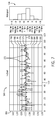
- FIG. 7 is an embodiment of a SQC chart and associated graphical feature (e.g., histogram) utilized in the SQC charting techniques described above.
- the SQC chart depicted in FIG. 7 is an I-chart 166.
- the y-axis 168 represents the value for the peak values (e.g., corresponding to peak firing pressure).
- the x-axis 170 represents the number of events or data points over time.
- the I-chart 166 depicts the observed peak values (e.g., corresponding to peak firing pressure) received form a knock sensor 23 for each combustion event (as represented by the pluses 172).
- the observed peak values 172 are time-ordered from left to right.
- the I-chart 166 depicts the moving range (e.g., short-term variability) between consecutive observation points (i.e., values 172) as represented by reference numeral 174.
- the I-chart 166 also depicts the average or baseline for the values as represented by line 176.
- the I-chart 166 also depicts various ⁇ threshold levels relative the baseline 176. For example, 1 ⁇ , -1 ⁇ , 1.5 ⁇ (bias line), -1.5 ⁇ (bias line), 2 ⁇ (warning line), -2 ⁇ (warning line), 3 ⁇ (action line), and -3 ⁇ (action line) are depicted as represented by lines 178, 180, 182, 184, 186, 188, 190, and 192, respectively.
- ⁇ threshold levels may be utilized as described above in FIGS. 3-5 .
- Fig. 7 also depicts a histogram 194 that graphically demonstrates the number of events whose value (as shown in the I-chart 166) fall within certain ⁇ threshold levels.
- a temporal filter e.g., window function
- Different temporal filters may be applied to the data from the knock sensor to look at other events (e.g., intake valve or other events described above).
- SCQ statistical techniques e.g., SQC charting techniques
- SCQ statistical techniques may be utilized to analyze specific bin or buckets of the analyzed signal (e.g., for non-Gaussian behavior or trends towards non-Gaussian behavior) to determine the occurrence or future occurrence of normal wearing maintenance items and/or abnormal component failures in advance.
- the systems and methods may utilized for diagnostics and advanced prognostics to minimize or avoid damage to the reciprocating device as well as any downtime for the equipment.
Landscapes
- Engineering & Computer Science (AREA)
- Chemical & Material Sciences (AREA)
- Combustion & Propulsion (AREA)
- Mechanical Engineering (AREA)
- General Engineering & Computer Science (AREA)
- Physics & Mathematics (AREA)
- General Physics & Mathematics (AREA)
- Combined Controls Of Internal Combustion Engines (AREA)
- Testing And Monitoring For Control Systems (AREA)
- Testing Of Engines (AREA)
- Testing Of Devices, Machine Parts, Or Other Structures Thereof (AREA)
Abstract
Description
- The subject matter disclosed herein relates to knock sensors, and more specifically, to utilizing knock sensors mounted to large, multi-cylinder reciprocating devices (e.g., combustion engine, compressors, etc.) in conjunction with standard quality control techniques to detect reciprocating device abnormalities.
- Combustion engines typically combust a carbonaceous fuel, such as natural gas, gasoline, diesel, and the like, and use the corresponding expansion of high temperature and pressure gases to apply a force to certain components of the engine, e.g., piston disposed in a cylinder, to move the components over a distance. Each cylinder may include one or more valves that open and close correlative with combustion of the carbonaceous fuel. For example, an intake valve may direct an oxidizer such as air into the cylinder, which is then mixed with fuel and combusted. Combustion fluids, e.g., hot gases, may then be directed to exit the cylinder via an exhaust valve. Accordingly, the carbonaceous fuel is transformed into mechanical motion, useful in driving a load. For example, the load may be a generator that produces electric power. During use, combustion engines may experience various noises, mechanical faults, or changes in conditions that may be difficult to detect and/or predict.
- Certain examples commensurate in scope with the originally claimed invention are summarized below. These examples are not intended to limit the scope of the claimed invention, but rather are intended only to provide a brief summary of possible forms of the invention. Indeed, the invention may encompass a variety of forms that may be similar to or different from the examples set forth below.
- In accordance with a first aspect, a system includes a controller configured to receive a signal acquired by the at least one knock sensor coupled to a reciprocating device, to sample the received signal, to analyze the sampled signal, and to utilize standard quality control (SQC) techniques to perform real-time diagnostics on the reciprocating device based on the analyzed signal.
- In accordance with a second aspect, a system includes a method for performing real-time diagnostics on a reciprocating device. The method includes utilizing a controller communicatively coupled to the reciprocating device for receiving a signal from at least one knock sensor coupled to the reciprocating device, sampling the received signal, analyzing the sampled signal, and utilizing SQC techniques to perform real-time diagnostics on the reciprocating device based on the analyzed signal.
- In accordance with a third aspect, a system includes a method for performing real-time diagnostics on a reciprocating device. The method includes utilizing a controller communicatively coupled to the reciprocating device for sampling a signal received from at least one knock sensor coupled to the reciprocating device, applying a temporal filter to the sampled signal to generate a temporal filtered signal, and applying a fast Fourier transform to the temporal filtered signal to generate a Fourier transformed signal. The method also includes utilizing the controller for generating a power spectral density from the Fourier transformed signal, and utilizing SQC techniques to perform real-time diagnostics on the reciprocating device based on the power spectral density.
- These and other features, aspects, and advantages of the present invention will become better understood when the following detailed description is read with reference to the accompanying drawings in which like characters represent like parts throughout the drawings, wherein:
-
FIG. 1 is a block diagram of an embodiment of a portion of an engine driven power generation system in accordance with aspects of the present disclosure; -
FIG. 2 is a side cross-sectional view of an embodiment of a piston assembly within a cylinder of the reciprocating engine shown inFIG. 1 in accordance with aspects of the present disclosure; -
FIG. 3 is a flow chart illustrating an embodiment of a process for monitoring engine health in accordance with aspects of the present disclosure; -
FIG. 4 is a flow chart illustrating an embodiment of a process for monitoring engine health utilizing fast Fourier transform (FFT) and power spectral density (PSD); -
FIG. 5 is a flow chart illustrating an embodiment of a process for monitoring engine health utilizing FFT, PSD, and different sigma threshold levels; -
FIG. 6 is an embodiment of a SQC chart (e.g., q-q plot) in accordance with aspects of the present disclosure; and -
FIG. 7 is an embodiment of a SQC chart (e.g., I-chart) and associated graphical feature in accordance with aspects of the present disclosure. - One or more specific embodiments of the present invention will be described below. In an effort to provide a concise description of these embodiments, all features of an actual implementation may not be described in the specification. It should be appreciated that in the development of any such actual implementation, as in any engineering or design project, numerous implementation-specific decisions must be made to achieve the developers' specific goals, such as compliance with system-related and business-related constraints, which may vary from one implementation to another. Moreover, it should be appreciated that such a development effort might be complex and time consuming, but would nevertheless be a routine undertaking of design, fabrication, and manufacture for those of ordinary skill having the benefit of this disclosure.
- When introducing elements of various embodiments of the present invention, the articles "a," "an," "the," and "said" are intended to mean that there are one or more of the elements. The terms "comprising," "including," and "having" are intended to be inclusive and mean that there may be additional elements other than the listed elements.
- During use, combustion engines (or other reciprocating devices such as compressors) may experience various noises due to mechanical faults or changes in conditions that may be difficult to detect and/or predict. Knock sensors may be utilized to monitor a combustion engine. Occasionally, the knock sensor system records a noise, such as an abnormal or undesired noise. Rather than ignore and discard the unidentifiable noises, it may be advantageous to monitor the noise overtime to identify any potential faults (e.g., engine faults) or abnormal conditions. These faults or conditions may include normal wearing maintenance items and/or abnormal component failures. It may also be advantageous to utilize SQC techniques (e.g., SQC charting techniques) for both diagnostics and advanced prognostics (e.g., to monitor for non-Gaussian behavior). By monitoring trends in certain noises detected by the knock sensor system, potential occurrences of failures may be detected earlier and corrective actions taken to reduce any potential collateral damage to the combustion engine caused by any engine failures, faults, and/or undesired changes in conditions. As described in further detail below, systems and method are provided for monitoring and analyzing abnormal noises within a combustion engine (or other reciprocating device) utilizing knock sensors utilizing SQC techniques, as described in more detail below.
- Turning to the drawings,
FIG. 1 illustrates a block diagram of an embodiment of a portion of an engine drivenpower generation system 8. As described in detail below, thesystem 8 includes an engine 10 (e.g., a reciprocating internal combustion engine) having one or more combustion chambers 12 (e.g., 1, 2, 3, 4, 5, 6, 7, 8, 10, 12, 14, 16, 18, 20, or more combustion chambers 12). Anair supply 14 is configured to provide a pressurizedoxidant 16, such as air, oxygen, oxygen-enriched air, oxygen-reduced air, or any combination thereof, to eachcombustion chamber 12. Thecombustion chamber 12 is also configured to receive a fuel 18 (e.g., a liquid and/or gaseous fuel) from afuel supply 19, and a fuel-air mixture ignites and combusts within eachcombustion chamber 12. The hot pressurized combustion gases cause apiston 20 adjacent to eachcombustion chamber 12 to move linearly within acylinder 26 and convert pressure exerted by the gases into a rotating motion, which causes ashaft 22 to rotate. Further, theshaft 22 may be coupled to aload 24, which is powered via rotation of theshaft 22. For example, theload 24 may be any suitable device that may generate power via the rotational output of thesystem 10, such as an electrical generator. Additionally, although the following discussion refers to air as theoxidant 16, any suitable oxidant may be used with the disclosed embodiments. Similarly, thefuel 18 may be any suitable gaseous fuel, such as natural gas, associated petroleum gas, propane, biogas, sewage gas, landfill gas, coal mine gas, for example. - The
system 8 disclosed herein may be adapted for use in stationary applications (e.g., in industrial power generating engines) or in mobile applications (e.g., in cars or aircraft). Theengine 10 may be a two-stroke engine, three-stroke engine, four-stroke engine, five-stroke engine, or six-stroke engine. Theengine 10 may also include any number ofcombustion chambers 12,pistons 20, and associated cylinders (e.g., 1-24). For example, in certain embodiments, thesystem 8 may include a large-scale industrial reciprocating engine having 4, 6, 8, 10, 16, 24 ormore pistons 20 reciprocating in cylinders. In some such cases, the cylinders and/or thepistons 20 may have a diameter of between approximately 13.5 - 34 centimeters (cm). In some embodiments, the cylinders and/or thepistons 20 may have a diameter of between approximately 10-40 cm, 15-25 cm, or about 15 cm. Thesystem 10 may generate power ranging from 10 kW to 10 MW. In some embodiments, theengine 10 may operate at less than approximately 1800 revolutions per minute (RPM). In some embodiments, theengine 10 may operate at less than approximately 2000 RPM, 1900 RPM, 1700 RPM, 1600 RPM, 1500 RPM, 1400 RPM, 1300 RPM, 1200 RPM, 1000 RPM, 900 RPM, or 750 RPM. In some embodiments, theengine 10 may operate between approximately 750-2000 RPM, 900-1800 RPM, or 1000-1600 RPM. In some embodiments, theengine 10 may operate at approximately 1800 RPM, 1500 RPM, 1200 RPM, 1000 RPM, or 900 RPM.Exemplary engines 10 may include General Electric Company's Jenbacher Engines (e.g., Jenbacher Type 2,Type 3, Type 4, Type 6 or J920 FleXtra) or Waukesha Engines (e.g., Waukesha VGF, VHP, APG, 275GL), for example. - The engine driven
power generation system 8 may include one or moreknock sensors 23 suitable for detecting engine "knock." Theknock sensor 23 may sense vibrations caused by the engine, such as vibration due to detonation, pre-ignition, and or pinging. In addition, the engine driven power generation system may include other sensors 27 (e.g., one or more temperature transducers) to detect other operating conditions (e.g., temperature (e.g., global temperature and/or temperature gradient) of a medium (e.g., cast iron) that the one ormore knock sensors 23 are coupled to). Theknock sensor 23 is shown communicatively coupled to an engine control unit (ECU) 25. During operations, signals from theknock sensor 23 are communicated to theECU 25 to determine if knocking conditions (e.g., pinging) exist. TheECU 25 may then adjustcertain engine 10 parameters to ameliorate or eliminate the knocking conditions. For example, theECU 25 may adjust ignition timing and/or adjust boost pressure to eliminate the knocking. As further described herein, theknock sensor 23 may additionally derive that certain vibrations should be further analyzed and categorized to monitor, for example, potentially undesired engine conditions. Although the following techniques are discussed in terms of a combustion engine, the same techniques may be applied to other reciprocating devices such as compressors. -
FIG. 2 is a side cross-sectional view of an embodiment of apiston assembly 25 having apiston 20 disposed within a cylinder 26 (e.g., an engine cylinder) of thereciprocating engine 10. Thecylinder 26 has an innerannular wall 28 defining a cylindrical cavity 30 (e.g., bore). Thepiston 20 may be defined by an axial axis ordirection 34, a radial axis ordirection 36, and a circumferential axis ordirection 38. Thepiston 20 includes a top portion 40 (e.g., a top land). Thetop portion 40 generally blocks thefuel 18 and theair 16, or a fuel-air mixture 32, from escaping from thecombustion chamber 12 during reciprocating motion of thepiston 20. - As shown, the
piston 20 is attached to acrankshaft 54 via a connectingrod 56 and apin 58. Thecrankshaft 54 translates the reciprocating linear motion of thepiston 24 into a rotating motion. As thepiston 20 moves, thecrankshaft 54 rotates to power the load 24 (shown inFIG. 1 ), as discussed above. As shown, thecombustion chamber 12 is positioned adjacent to thetop land 40 of thepiston 24. Afuel injector 60 provides thefuel 18 to thecombustion chamber 12, and anintake valve 62 controls the delivery ofair 16 to thecombustion chamber 12. Anexhaust valve 64 controls discharge of exhaust from theengine 10. However, it should be understood that any suitable elements and/or techniques for providingfuel 18 andair 16 to thecombustion chamber 12 and/or for discharging exhaust may be utilized, and in some embodiments, no fuel injection is used. In operation, combustion of thefuel 18 with theair 16 in thecombustion chamber 12 cause thepiston 20 to move in a reciprocating manner (e.g., back and forth) in theaxial direction 34 within thecavity 30 of thecylinder 26. - During operations, when the
piston 20 is at the highest point in thecylinder 26 it is in a position called top dead center (TDC). When thepiston 20 is at its lowest point in thecylinder 26, it is in a position called bottom dead center (BDC). As thepiston 20 moves from top to bottom or from bottom to top, thecrankshaft 54 rotates one half of a revolution. Each movement of thepiston 20 from top to bottom or from bottom to top is called a stroke, andengine 10 embodiments may include two-stroke engines, three-stroke engines, four-stroke engines, five-stroke engine, six-stroke engines, or more. - During
engine 10 operations, a sequence including an intake process, a compression process, a power process, and an exhaust process typically occurs. The intake process enables a combustible mixture, such as fuel and air, to be pulled into thecylinder 26, thus theintake valve 62 is open and theexhaust valve 64 is closed. The compression process compresses the combustible mixture into a smaller space, so both theintake valve 62 and theexhaust valve 64 are closed. The power process ignites the compressed fuel-air mixture, which may include a spark ignition through a spark plug system, and/or a compression ignition through compression heat. The resulting pressure from combustion then forces thepiston 20 to BDC. The exhaust process typically returns thepiston 20 to TDC while keeping theexhaust valve 64 open. The exhaust process thus expels the spent fuel-air mixture through theexhaust valve 64. It is to be noted that more than oneintake valve 62 andexhaust valve 64 may be used percylinder 26. - The depicted
engine 10 also includes acrankshaft sensor 66, theknock sensor 23, and the engine control unit (ECU) 25, which includes aprocessor 72 andmemory 74. Thecrankshaft sensor 66 senses the position and/or rotational speed of thecrankshaft 54. Accordingly, a crank angle or crank timing information may be derived. That is, when monitoring combustion engines, timing is frequently expressed in terms ofcrankshaft 54 angle. For example, a full cycle of a fourstroke engine 10 may be measured as a 720° cycle. Theknock sensor 23 may be a Piezo-electric accelerometer, a microelectromechanical system (MEMS) sensor, a Hall effect sensor, a magnetorestrictive sensor, and/or any other sensor designed to sense vibration, acceleration, sound, and/or movement. In other embodiments,sensor 23 may not be a knock sensor, but any sensor that may sense vibration, pressure, acceleration, deflection, or movement. - Because of the percussive nature of the
engine 10, theknock sensor 23 may be capable of detecting signatures even when mounted on the exterior of thecylinder 26. However, theknock sensor 23 may be disposed at various locations in or about thecylinder 26. Additionally, in some embodiments, asingle knock sensor 23 may be shared, for example, with one or moreadjacent cylinders 26. In other embodiments, eachcylinder 26 may include one or more knock sensors 23 (e.g., one or more arrays ofknock sensors 23 arranged along one or more planes through the engine 10). Thecrankshaft sensor 66 and theknock sensor 23 are shown in electronic communication with the engine control unit (ECU) 25. TheECU 25 includes theprocessor 72 and the memory 74 (e.g., a machine-readable medium). Thememory 74 may store non-transitory code or computer instructions that may be executed by theprocessor 72. TheECU 25 monitors and controls and operation of theengine 10, for example, by adjusting combustion timing,valve - Advantageously, the techniques described herein may use the
ECU 25 to receive, acquire, or sample data (e.g., noise signals) from the one ormore crankshaft sensors 66 and/or the one ormore knock sensors 23. In order to detect and/or locate any coincident noises within theengine 10, data from the sensors (e.g., knock sensors and/or crankshaft sensors 66) may be sampled at both the same rate and taken at the same time. In certain embodiments, the noise signals utilized to detect and/or locate coincident noises may be received solely from the one ormore knock sensors 23. In other embodiments, the noise signals may be utilized to detect and/or locate coincident noises may be received from both thecrankshaft sensor 66 and theknock sensors 23. Each noise signal represents a noise signature of theengine 10 detected at arespective knock sensor 23. In certain embodiments, theECU 25 creates a "noise" signature by plotting theknock sensor 23 data against thecrankshaft 54 position. TheECU 25 may then go through the process of analyzing the data to derive normal (e.g.., known and expected noises) and/or abnormal signatures (e.g., unknown or unexpected noises). TheECU 25 may then characterize the abnormal signatures (e.g., detect and/or locate coincident noises), as described in more detail below. By providing for signature analysis, the techniques described herein may enable more optimal and more efficient operations and maintenance of theengine 10. -
FIG. 3 is a flow chart illustrating an embodiment of aprocess 76 for monitoring engine health (e.g., theengine 10 inFIG. 2 ). A similar process may be utilized in monitoring health of a reciprocating device (e.g., compressor). Theprocess 76 may be implemented as computer instructions or executable code stored in thememory 74 and executable by theprocessor 72 of theECU 25 or any reciprocating device controller. Theprocess 76 includes receiving one or more signals from one ormore knock sensors 23 coupled to the engine 10 (block 78). Theprocess 76 also includes sampling and analyzing the one or more signals received from the one or more knock sensors 23 (block 80). In certain embodiments, a single signal from asingle knock sensor 23 may be continuously sampled and analyzed. In other embodiments, signals frommultiple knock sensors 23 may be continuously sampled and analyzed, individually and/or in combination. Theknock sensor 23 may be sampled in time buckets of equal sized octants or hexa-decants. For example, if theengine 10 is a four-stroke engine, two rotations of the crank occur for every combustion cycle. Theknock sensors 23 would sample every 45 or 90 crank angle degrees during the four stroke cycle for a total of 8 or 16 times for each combustion event, respectively. In certain embodiments, a minimal filter may be applied (e.g., anti-aliasing filter) during the sampling of the received signals. - As described in greater detail, analyzing the sampled signals may include processing the sampled signals, for example, via temporal filtering. Temporal filtering assists in analyzing the signal because a small window of the signals is sampled (e.g., non-compression events during a combustion cycle). Temporal filtering may include applying a window function to the sampled signals prior to applying a fast Fourier transform (FFT). The window functions may include a Hamming window, flat top window, Blackman window, or any other type window function that may temporally filter the signals to enable analysis of the desired portion of the sampled signals. Certain mechanical failures or events in the engine 10 (or a reciprocating device such as a compressor) are associated with specific bands (e.g., specific frequencies within a spectrum of buckets or bins) and/or specific non-compression windowed events. A non-exhaustive list of these events may include abnormalities in peak firing pressure, an intake or exhaust valve sticking open or closed, a damaged intake or exhaust valve, damaged valve train, worn or damaged piston, worn or damaged piston pin and/or bushings, worn or damaged connecting rod and/or bearings, loose connecting rod bolts, loose counterweights and/or bolts, damaged main bearings, cam shaft lobe wear, broken or damaged piston rings, excessive blow-by in combustion cylinder, severely fretted cylinder liner, and/or severely scored cylinder liner. By temporal filtering the sampled signals, particular frequency and magnitude bins associated with specific events may be analyzed (subsequent to FFT). Subsequent to temporal filtering, analysis of the sampled signals may also include applying FFT and then obtaining a power spectral density (PSD) (magnitude) from the sampled signals. The power spectral density includes several spectral bins or buckets. An array of the spectral bins or buckets (e.g., associated with a specific event of interest such as peak firing pressure) obtained from multiple combustion cycles (or stroke cycles in the case of reciprocating devices such as compressors) may be averaged to obtain a baseline for each bin or bucket. In certain embodiments, each event (combustion cycle or combustion event) may have a weighted coefficient applied to generate a weighted average for the respective baseline.
- As the engine wears, specific frequency bins associated with specific events (e.g., engine failures, faults, or abnormal conditions) may increase, while others decrease relative to the baseline. The
process 76 further includes monitoring engine health utilizing SQC techniques such as SQC charting statistics (block 82) (e.g., to enable statistical process control). Monitoring engine health may include monitoring changes in real time (i.e., controlling the engine by receiving and processing the data from theknock sensors 23 and returning the results sufficiently quickly to affect the engine at that time) in the specific spectral bins or buckets to enable performance of diagnostics or advanced prognostics. A variety of SQC charting techniques may be utilized to generate control charts (e.g., process charts or quality control charts) that determine whether a sample of data (data from the knock sensors 23) falls within the common or normal range of variation. A variety of control charts may be utilized (e.g. I-Chart, q-q plot, etc.). Additional graphical techniques may also be utilized (e.g., such as histograms) in conjunction with the control charts. In certain embodiments, a chart may be displayed for a multidimensional array of spectral bins, where each bin includes an indicator that represents the trend in magnitude of the specific bin (e.g., an arrow pointing up for an increase in magnitude, an arrow pointing down for a decrease in magnitude, a horizontal arrow for no change in magnitude). In certain embodiments, the indicators may be color coated to indicate the severity of the trend (e.g., red for a 3-σ deviation from a baseline, yellow or orange for a 2-σ deviation from a baseline, etc.). Multiple control charts and/or graphical features may be generated for the different events described above. - In certain embodiments, monitoring engine health (e.g., long term engine health) may include setting sigma (σ) threshold levels (e.g., 3-σ threshold levels, 2-σ threshold levels, etc.) relative to the respective baselines and comparing the information derived from the presently sampled signals to look for trends and/or non-Gaussian behavior in the information obtained from the
knock sensors 23. In certain embodiments, the baselines are continuously changing as new information is collected from theknock sensors 23. In other words, the baselines are trended and not reset (i.e., noise floor grows as a function of engine wearing). - While monitoring engine health, the
process 76 includes logging and/or storing data gathered from the knock sensors and their subsequent analysis (block 84). The data may be stored on thememory 74 of theECU 25 and/or in a memory of a remote device. The data stored may include flagged events and/or errors associated with deviations in the spectral bins (e.g., deviation of magnitude of one or more spectral bins of 2-σ or greater relative to respective baselines). Theprocess 76 also includes providing an indication of engine health (block 86). This may include providing a warning (e.g., warning flag) that certain frequency bands (i.e., spectral bins) are trending toward non-Gaussian behavior (e.g., deviation of 2-σ but less than 3-σ relative to a baseline). Warning (e.g., warning flags) may also be provided that certain frequency bands are at non-Gaussian levels (e.g., at or greater 3-σ relative to a baseline). The warnings may include providing visual or textual warnings on a display coupled to theECU 25 or on a remote device associated via a network (e.g., controller area network) with theECU 25. Warnings may include communicating error codes (e.g., associated with specific events such as those described above) via proprietary software. Providing indications of engine health may also include displaying control charts generated utilizing the SQC charting techniques as well as other graphical features (e.g., histograms). - The
process 76 further includes, in certain embodiments, outputting a control action that affects the engine 10 (block 88). Examples of control action include adjusting a condition within the engine (e.g., speed, load, positions of valves, etc.), shutting down the engine, and other actions. Outputting a control that affects theengine 10 enables closed-loop control of theengine 10 in response to the information obtained from theknock sensors 23. In certain embodiments, control actions may only be outputted when certain frequency bands have reached non-Gaussian levels (e.g., at or greater 3-σ relative to a baseline). In other embodiments, control actions may be outputted for certain frequency bands trending toward non-Gaussian levels (e.g., deviation of 2-σ but less than 3-σ relative to a baseline) as well as frequency bands reaching non-Gaussian levels (e.g., at or greater 3-σ relative to a baseline). -
FIG. 4 is a flow chart illustrating an embodiment of aprocess 90 for monitoring engine health (e.g., theengine 10 inFIG. 2 ) utilizing FFT and PSD. A similar process may be utilized in monitoring health of a reciprocating device (e.g., compressor). Theprocess 90 may be implemented as computer instructions or executable code stored in thememory 74 and executable by theprocessor 72 of theECU 25 or any reciprocating device controller. Theprocess 90 includes receiving one or more signals from one ormore knock sensors 23 coupled to the engine 10 (block 92). Theprocess 76 also includes sampling the one or more signals received from the one or more knock sensors 23 (block 92) as described above inFIG. 3 . In certain embodiments, minimal filtering may be applied when sampling the received signals. For example, anti-aliasing filtering may be applied when sampling the received signals (e.g., to restrict bandwidth of the signal to satisfy the sampling theorem). - In addition,
process 90 includes processing the sampled signals (block 96), for example, via temporal filtering. Temporal filtering assists in analyzing the signal because a small window of the signals is sampled (e.g., non-compression events during a combustion cycle). Temporal filtering may include applying a window function to the sampled signals prior to applying a FFT. The window functions may include a Hamming window, flat top window, Blackman window, or any other type window function that may temporally filter the signals to enable analysis of the desired portion of the sampled signals. Certain mechanical failures or events in theengine 10 as described above are associated with specific bands (e.g., specific frequencies within a spectrum of buckets or bins) and/or specific non-compression windowed events. By temporal filtering the sampled signals, particular frequency and magnitude bins associated with specific events may be analyzed (subsequent to FFT). - Subsequent to temporal filtering, the
process 90 includes applying FFT to the temporally filtered, sampled signals (block 98) to generate Fourier transformed signals. Theprocess 90 includes obtaining or generating a PSD (magnitude) from each of the Fourier transformed signals (block 100). The power spectral density includes several spectral bins or buckets. An array of the spectral bins or buckets (e.g., associated with a specific event of interest such as peak firing pressure) obtained from multiple combustion cycles (or stroke cycles in the case of reciprocating devices such as compressors) may be averaged to obtain abaseline 102 for each bin or bucket (block 104). In certain embodiments, the each event (combustion cycle or combustion event) may have a weighted coefficient applied to generate a weighted average for the respective baseline. - As the engine wears, specific frequency bins associated with specific events (e.g., engine failures, faults, or abnormal conditions) may increase, while others decrease relative to the baseline. The
process 90 further includes monitoring engine health utilizing SQC techniques such as SQC charting statistics (block 106) (e.g., to enable statistical process control). Monitoring engine health may include monitoring changes in real time (i.e., controlling the engine by receiving and processing the data from theknock sensors 23 and returning the results sufficiently quickly to affect the engine at that time) in the specific spectral bins or buckets to enable performance of diagnostics or advanced prognostics. A variety of SQC charting techniques may be utilized to generate control charts (e.g., process charts or quality control charts) that determine whether a sample of data (data from the knock sensors 23) falls within the common or normal range of variation. A variety of control charts may be utilized (e.g. I-Chart, q-q plot, etc.). Additional graphical techniques may also be utilized (e.g., such as histograms) in conjunction with the control charts. In certain embodiments, a chart may be displayed for a multidimensional array of spectral bins, where each bin includes an indicator that represents the trend in magnitude of the specific bin (e.g., an arrow pointing up for an increase in magnitude, an arrow pointing down for a decrease in magnitude, a horizontal arrow for no change in magnitude). In certain embodiments, the indicators may be color coated to indicate the severity of the trend (e.g., red for a 3-σ deviation from a baseline, yellow or orange for a 2-σ deviation from a baseline, etc.). Multiple control charts and/or graphical features may be generated for the different events described above. - In certain embodiments, monitoring engine health (e.g., long term engine health) may include identifying potential issues in engine health (e.g., a trend toward non-Gaussian behavior relative the baseline 102) based on changes in specific frequency bands associated with particular events (block 108) utilizing the SQC charting statistics. If potential issues are identified, the
process 90 includes logging and/or storing data gathered from the knock sensors and their subsequent analysis related to the potential issue (block 110). The data may be stored on thememory 74 of theECU 25 and/or in a memory of a remote device. The data stored may include flagged events and/or errors associated with deviations in the spectral bins (e.g., deviation of magnitude of one or more spectral bins between 2-σ and 3-σ relative to respective baselines). If potential issues are identified, theprocess 90 also includes providing an indication of the potential issue with the engine (block 112). This may include providing a warning (e.g., warning flag) that certain frequency bands (i.e., spectral bins) are trending toward non-Gaussian behavior (e.g., deviation of 2-σ but less than 3-σ relative to a baseline). The warnings may include providing visual or textual warnings on a display coupled to theECU 25 or on a remote device associated via a network (e.g., controller area network) with theECU 25. Providing indications of the potential issue with the engine may also include displaying control charts generated utilizing the SQC charting techniques as well as other graphical features (e.g., histograms). - In certain embodiments, monitoring engine health (e.g., long term engine health) may include identifying current or actual issues (e.g., imminent) in engine health (e.g., data displaying non-Gaussian behavior relative the baseline 102) based on changes in specific frequency bands associated with particular events (block 114) utilizing the SQC charting statistics. If potential issues are identified, the
process 90 includes logging and/or storing data gathered from the knock sensors and their subsequent analysis related to the current or actual issue (block 116). The data may be stored on thememory 74 of theECU 25 and/or in a memory of a remote device. The data stored may include flagged events and/or errors associated with deviations in the spectral bins (e.g., deviation of magnitude of one or more spectral bins greater than 3-σ relative to respective baselines). If current or actual issues are identified, theprocess 90 also includes providing an indication of the current or actual issue with the engine (block 118). This may include providing a warning (e.g., warning flag) that certain frequency bands (i.e., spectral bins) are displaying non-Gaussian behavior (e.g., deviation at or greater than 3-σ relative to a baseline). The warnings may include providing visual or textual warnings on a display coupled to theECU 25 or on a remote device associated via a network (e.g., controller area network) with theECU 25. Warnings may include communicating error codes (e.g., associated with specific events such as those described above) via proprietary software. Providing indications of the potential issue with the engine may also include displaying control charts generated utilizing the SQC charting techniques as well as other graphical features (e.g., histograms). - The
process 90 further includes, in certain embodiments, outputting a control action that affects the engine 10 (block 120) in response to identifying current or actual issues in engine health based on the SQC charting statistics. Examples of control action include adjusting a condition within the engine (e.g., speed, load, positions of valves, etc.), shutting down the engine, and other actions. Outputting a control that affects theengine 10 enables closed-loop control of theengine 10 in response to the information obtained from theknock sensors 23. -
FIG. 5 is a flow chart illustrating an embodiment of aprocess 122 for monitoring engine health (e.g., theengine 10 inFIG. 2 ) utilizing FFT, PSD, and different sigma (σ) threshold levels. A similar process may be utilized in monitoring health of a reciprocating device (e.g., compressor). Theprocess 122 may be implemented as computer instructions or executable code stored in thememory 74 and executable by theprocessor 72 of theECU 25 or reciprocating device controller. Theprocess 122 includes receiving one or more signals from one ormore knock sensors 23 coupled to the engine 10 (block 124), sampling the one or more signals received from the one or more knock sensors 23 (block 126), and processing the sampled signals (block 128) as described above inFIG. 4 . In addition, theprocess 122 includes applying a FFT to generate Fourier transformed signals (block 130) and obtaining or generating a PSD for each of the Fourier transformed signals (block 132) as described above inFIG. 4 . - The power spectral density includes several spectral bins or buckets. An array of the spectral bins or buckets (e.g., associated with a specific event of interest such as peak firing pressure) obtained from multiple combustion cycles (or stroke cycles in the case of reciprocating devices such as compressors) may be averaged to obtain a
baseline 134 for each bin or bucket (block 136). In certain embodiments, the each event (combustion cycle or combustion event) may have a weighted coefficient applied to generate a weighted average for the respective baseline. - The
process 122 includes setting 2-σ and 3-σ threshold levels relative to each baseline (block 138). In certain embodiments, additional threshold levels may be set (e.g., 1-σ, 1.5-σ, etc.). Theprocess 122 also includes comparing specific bins or buckets to their corresponding baselines to monitor for non-Gaussian behavior (block 140). Theprocess 122 includes determining if specific bin or buckets deviate from their respective baselines at or beyond the respective 2-σ threshold level (block 142). If the specific bin or buckets do not deviate from their respective baselines by at least 2-σ, then theprocess 122 includes continuing the compare specific bins or buckets to their corresponding baselines (block 140). However, if the specific bin or buckets do deviate at least 2-σ from their respective baselines, theprocess 122 includes determining if the specific bins or buckets deviate from their respective baselines at or beyond the respective 3-σ threshold level (block 144).Blocks process 122 includes logging or storing the issue (block 146) and/or providing an indication or warning with regard to the trend toward non-Gaussian behavior (block 148) as described above inFIGS. 3 and4 . If the specific bin or buckets do deviate from their respective baselines by at least 3-σ, then theprocess 122 includes logging or storing the issue (block 150), providing an indication or warning with regard to the non-Gaussian behavior (block 152), and/or outputting a control action with regard to the engine (or reciprocating device) as described above inFIGS. 3 and4 . -
FIG. 6 is an embodiment of an example of a SQC chart utilized in the SCQ charting techniques described above. The SQC chart depicted inFIG. 6 is a q-q plot (also known as quantile-quantile plot or Quantile plot) 156. Theq-q plot 156 depicts observed peak values (e.g., corresponding to peak firing pressure) received from aknock sensor 23 for each combustion event (as represented by the pluses 158) relative to astraight line 160. Thestraight line 160 represents a Weibull plot of an empirical cumulative distribution function that has been linearized. The y-axis 162 represents the value for the peak values and thex-axis 164 represents the theoretical quantile or standardized expected values. A temporal filter (e.g., window function) is applied to the data to specifically analyze peak firing pressure. Different temporal filters may be applied to the data from the knock sensor to look at other events (e.g., intake valve or other events described above). -
FIG. 7 is an embodiment of a SQC chart and associated graphical feature (e.g., histogram) utilized in the SQC charting techniques described above. The SQC chart depicted inFIG. 7 is an I-chart 166. The y-axis 168 represents the value for the peak values (e.g., corresponding to peak firing pressure). Thex-axis 170 represents the number of events or data points over time. The I-chart 166 depicts the observed peak values (e.g., corresponding to peak firing pressure) received form aknock sensor 23 for each combustion event (as represented by the pluses 172). The observedpeak values 172 are time-ordered from left to right. The I-chart 166 depicts the moving range (e.g., short-term variability) between consecutive observation points (i.e., values 172) as represented byreference numeral 174. The I-chart 166 also depicts the average or baseline for the values as represented byline 176. The I-chart 166 also depicts various σ threshold levels relative thebaseline 176. For example, 1 σ, -1 σ, 1.5σ (bias line), -1.5 σ (bias line), 2 σ (warning line), -2 σ (warning line), 3 σ (action line), and -3 σ (action line) are depicted as represented bylines FIGS. 3-5 .Fig. 7 also depicts ahistogram 194 that graphically demonstrates the number of events whose value (as shown in the I-chart 166) fall within certain σ threshold levels. A temporal filter (e.g., window function) is applied to the data to specifically analyze peak firing pressure. Different temporal filters may be applied to the data from the knock sensor to look at other events (e.g., intake valve or other events described above). - Technical effects of the disclosed embodiments include providing systems and methods for monitoring the health of a reciprocating device (e.g., combustion engine, compressor, etc.). Utilizing information or data gathered from the knock sensors, SCQ statistical techniques (e.g., SQC charting techniques) may be utilized to analyze specific bin or buckets of the analyzed signal (e.g., for non-Gaussian behavior or trends towards non-Gaussian behavior) to determine the occurrence or future occurrence of normal wearing maintenance items and/or abnormal component failures in advance. The systems and methods may utilized for diagnostics and advanced prognostics to minimize or avoid damage to the reciprocating device as well as any downtime for the equipment.
- This written description uses examples to disclose the invention, including the best mode, and also to enable any person skilled in the art to practice the invention, including making and using any devices or systems and performing any incorporated methods. The patentable scope of the invention is defined by the claims, and may include other examples that occur to those skilled in the art. Such other examples are intended to be within the scope of the claims if they have structural elements that do not differ from the literal language of the claims, or if they include equivalent structural elements with insubstantial differences from the literal languages of the claims.
- Various aspects and embodiments of the present invention are defined by the following numbered clauses:
- 1. A system, comprising:
- a controller configured to receive a signal acquired by at least one knock sensor coupled to a reciprocating device, to sample the received signal, to analyze the sampled signal, and to utilize standard quality control (SQC) techniques to perform real-time diagnostics on the reciprocating device based on the analyzed signal.
- 2. The system of
clause 1, wherein SQC techniques comprise SQC charting statistics. - 3. The system of any preceding clause, wherein the controller is configured to analyze the sampled signal by temporal filtering the sampled signal to generate a temporal filtered signal.
- 4. The system of any preceding clause, wherein the controller is configured to temporal filter the sampled signal by utilizing a window function.
- 5. The system of any preceding clause, wherein the controller is configured to apply a fast Fourier transform to the temporal filtered signal to generate a Fourier transformed signal.
- 6. The system of any preceding clause, wherein the controller is configured to generate a power spectral density having a plurality of spectral bins from the Fourier transformed signal.
- 7. The system of any preceding clause, wherein the controller is configured to average each spectral bin of the plurality of spectral bins over a plurality of cycles to generate a respective baseline for each spectral bin.
- 8. The system of any preceding clause, wherein the controller is configured to set 2 sigma and 3 sigma threshold levels for each spectral bin relative to the respective baseline.
- 9. The system of any preceding clause, wherein the controller is configured to compare one or more spectral bins associated with known reciprocating device or reciprocating device failures from the plurality of spectral bins to their respective baselines and associated 2 sigma and 3 sigma threshold levels.
- 10. The system of any preceding clause, wherein the controller is configured to provide an indication if the one or more spectral bins deviate from their respective baselines by at least the 2 sigma threshold level.
- 11. The system of any preceding clause, wherein the controller is configured to output a control action with respect to the reciprocating device if the one or more spectral bins deviate from their respective baselines by at least the 3 sigma threshold level.
- 12. A method for performing real-time diagnostics on a reciprocating device, comprising:
- utilizing a controller communicatively coupled to the reciprocating device for:
- receiving a signal from at least one knock sensor coupled to the reciprocating device;
- sampling the received signal;
- analyzing the sampled signal; and
- utilize standard quality control (SQC) techniques to perform real-time diagnostics on the reciprocating device based on the analyzed signal.
- utilizing a controller communicatively coupled to the reciprocating device for:
- 13. The method of any preceding clause, wherein analyzing the sampled signal comprises temporal filtering the sampled signal to generate a temporal filtered signal.
- 14. The method of any preceding clause, wherein temporal filtering the sampled signal comprises applying a window function to sampled signal.
- 15. The method of any preceding clause, wherein analyzing the sampled signal comprises applying a fast Fourier transform to the temporal filtered signal to generate a Fourier transformed signal.
- 16. The method of any preceding clause, wherein analyzing the sampled signal comprises generating a power spectral density having a plurality of spectral bins from the Fourier transformed signal.
- 17. The method of any preceding clause, comprising averaging each spectral bin of the plurality of spectral bins over a plurality of cycles to generate a respective baseline for each spectral bin, and to set 2 sigma and 3 sigma threshold levels for each spectral bin relative to a respective baseline.
- 18. The method of any preceding clause, comprising comparing one or more spectral bins associated with known reciprocating device or reciprocating device component failures from the plurality of spectral bins to their respective baselines and associated 2 sigma and 3 sigma threshold levels.
- 19. The method of any preceding clause, comprising providing an indication if the one or more spectral bins deviate from their respective baselines by at least the 2 sigma threshold level, and outputting a control action with respect the reciprocating device if the one or more spectral bins deviate from their respective baselines by at least the 3 sigma threshold level.
- 20. A method for performing real-time diagnostics on a reciprocating device, comprising:
- utilizing a controller communicatively coupled to the reciprocating device for:
- sampling a signal received from at least one knock sensor coupled to the reciprocating device;
- applying a temporal filter to the sampled signal to generate a temporal filtered signal;
- applying a fast Fourier transform to the temporal filtered signal to generate a Fourier transformed signal;
- generating a power spectral density from the Fourier transformed signal; and
- utilize standard quality control (SQC) techniques to perform real-time diagnostics on the reciprocating device based on the power spectral density.
- utilizing a controller communicatively coupled to the reciprocating device for:
Claims (15)
- A system (8), comprising:a controller (25) configured to receive a signal acquired by at least one knock sensor (23) coupled to a reciprocating device (10), to sample the received signal, to analyze the sampled signal, and to utilize standard quality control (SQC) techniques to perform real-time diagnostics on the reciprocating device based on the analyzed signal.
- The system (8) of claim 1, wherein SQC techniques comprise SQC charting statistics.
- The system (8) of either of claim 1 or 2, wherein the controller (25) is configured to analyze the sampled signal by temporal filtering the sampled signal to generate a temporal filtered signal.
- The system (8) of claim 3, wherein the controller (25) is configured to temporal filter the sampled signal by utilizing a window function.
- The system (8) of either of claim 3 or 4, wherein the controller (25) is configured to apply a fast Fourier transform to the temporal filtered signal to generate a Fourier transformed signal.
- The system (8) of claim 5, wherein the controller (25) is configured to generate a power spectral density having a plurality of spectral bins from the Fourier transformed signal.
- The system (8) of claim 6, wherein the controller (25) is configured to average each spectral bin of the plurality of spectral bins over a plurality of cycles to generate a respective baseline for each spectral bin.
- The system (8) of claim 7, wherein the controller (25) is configured to set 2 sigma and 3 sigma threshold levels for each spectral bin relative to the respective baseline.
- The system (8) of claim 8, wherein the controller (25) is configured to compare one or more spectral bins associated with known reciprocating device or reciprocating device (10) failures from the plurality of spectral bins to their respective baselines and associated 2 sigma and 3 sigma threshold levels.
- The system (8) of claim 9, wherein the controller (25) is configured to provide an indication if the one or more spectral bins deviate from their respective baselines by at least the 2 sigma threshold level.
- The system (8) of claim 10, wherein the controller (25) is configured to output a control action with respect to the reciprocating device (10) if the one or more spectral bins deviate from their respective baselines by at least the 3 sigma threshold level.
- A method (76) for performing real-time diagnostics on a reciprocating device (10), comprising:utilizing a controller (25) communicatively coupled to the reciprocating device (10) for:receiving (78) a signal from at least one knock sensor (23) coupled to the reciprocating device;sampling (80) the received signal;analyzing (80) the sampled signal; andutilize standard quality control (SQC) techniques (82) to perform real-time diagnostics on the reciprocating device (10) based on the analyzed signal.
- The method (76) of claim 12, wherein analyzing the sampled signal comprises temporal filtering the sampled signal to generate a temporal filtered signal.
- The method (76) of claim 13, wherein temporal filtering the sampled signal comprises applying a window function to the sampled signal.
- The method (76) of either of claim 13 or 14, wherein analyzing the sampled signal comprises applying a fast Fourier transform to the temporal filtered signal to generate a Fourier transformed signal.
Applications Claiming Priority (1)
| Application Number | Priority Date | Filing Date | Title |
|---|---|---|---|
| US14/591,192 US9803567B2 (en) | 2015-01-07 | 2015-01-07 | System and method for detecting reciprocating device abnormalities utilizing standard quality control techniques |
Publications (2)
| Publication Number | Publication Date |
|---|---|
| EP3043053A1 true EP3043053A1 (en) | 2016-07-13 |
| EP3043053B1 EP3043053B1 (en) | 2019-07-31 |
Family
ID=55085555
Family Applications (1)
| Application Number | Title | Priority Date | Filing Date |
|---|---|---|---|
| EP16150238.0A Active EP3043053B1 (en) | 2015-01-07 | 2016-01-05 | System and method for detecting reciprocating device abnormalities utilizing standard quality control techniques |
Country Status (7)
| Country | Link |
|---|---|
| US (1) | US9803567B2 (en) |
| EP (1) | EP3043053B1 (en) |
| JP (1) | JP6671955B2 (en) |
| KR (1) | KR102245696B1 (en) |
| CN (1) | CN105937459B (en) |
| BR (1) | BR102016000207B1 (en) |
| CA (1) | CA2916466C (en) |
Families Citing this family (15)
| Publication number | Priority date | Publication date | Assignee | Title |
|---|---|---|---|---|
| US10054043B2 (en) * | 2015-04-07 | 2018-08-21 | General Electric Company | Systems and methods for estimating a time of an engine event |
| US9989004B2 (en) * | 2016-07-29 | 2018-06-05 | Caterpillar Inc. | System for determining piston pin bore wear |
| WO2018044294A1 (en) * | 2016-08-31 | 2018-03-08 | General Electric Company | System and method for determining the timing of an engine event |
| KR102586917B1 (en) * | 2018-08-27 | 2023-10-10 | 현대자동차주식회사 | System and method for prevention seizure of bearing using knocking sensor |
| US11506570B2 (en) * | 2018-08-27 | 2022-11-22 | Hyundai Motor Company | Method for sensing damage of bearing of engine using vibration signal |
| DE102018126501B3 (en) * | 2018-10-24 | 2019-12-19 | Iav Gmbh Ingenieurgesellschaft Auto Und Verkehr | Method for predicting the maintenance of components of an internal combustion engine using a structure-borne noise sensor |
| EP3994570A4 (en) | 2019-07-01 | 2023-06-14 | FW Murphy Production Controls, LLC | INTUITIVE NATURAL GAS COMPRESSOR MONITORING SYSTEM |
| US12061971B2 (en) * | 2019-08-12 | 2024-08-13 | Micron Technology, Inc. | Predictive maintenance of automotive engines |
| US12249189B2 (en) | 2019-08-12 | 2025-03-11 | Micron Technology, Inc. | Predictive maintenance of automotive lighting |
| US12497055B2 (en) | 2019-08-21 | 2025-12-16 | Micron Technology, Inc. | Monitoring controller area network bus for vehicle control |
| US11042350B2 (en) | 2019-08-21 | 2021-06-22 | Micron Technology, Inc. | Intelligent audio control in vehicles |
| US12210401B2 (en) | 2019-09-05 | 2025-01-28 | Micron Technology, Inc. | Temperature based optimization of data storage operations |
| US11250648B2 (en) | 2019-12-18 | 2022-02-15 | Micron Technology, Inc. | Predictive maintenance of automotive transmission |
| US11635348B2 (en) * | 2021-02-03 | 2023-04-25 | Hyundai Motor Company | System and method for detecting damage to bearing of engine using knocking sensor |
| CN118670456B (en) * | 2024-07-26 | 2025-05-13 | 杭州朗阳科技有限公司 | A multi-sensor based health assessment method for mobile equipment |
Citations (7)
| Publication number | Priority date | Publication date | Assignee | Title |
|---|---|---|---|---|
| EP0731349A1 (en) * | 1995-03-10 | 1996-09-11 | Motorola, Inc. | Spectral knock detection method and system therefor |
| US20040236494A1 (en) * | 2001-06-26 | 2004-11-25 | Debotton Gal | Universal diagnostic method and system for engines |
| US20080077307A1 (en) * | 2006-09-26 | 2008-03-27 | Wiles Matthew A | Discrete variable valve lift diagnostic control system |
| US20080229806A1 (en) * | 2007-03-23 | 2008-09-25 | Cubr Anthony E | Knock system with detection zones |
| US20090276147A1 (en) * | 2008-05-01 | 2009-11-05 | Gm Global Technology Operations, Inc. | Engine knock diagnostic |
| US20100174472A1 (en) * | 2009-01-06 | 2010-07-08 | Mitsubishi Electric Corporation | Control apparatus for internal combustion engine |
| US20130151127A1 (en) * | 2011-12-12 | 2013-06-13 | Mazda Motor Corporation | Internal combustion engine control apparatus |
Family Cites Families (108)
| Publication number | Priority date | Publication date | Assignee | Title |
|---|---|---|---|---|
| EP0293573B1 (en) * | 1987-04-06 | 1991-04-24 | Mazda Motor Corporation | Engine knock detecting and control system |
| KR930009907B1 (en) | 1988-10-04 | 1993-10-13 | 미쯔비시 덴끼 가부시끼가이샤 | Control apparatus for internal combustion engine |
| GB8910319D0 (en) | 1989-05-05 | 1989-06-21 | Austin Rover Group | A spark ignited internal combustion engine and a control system therefor |
| EP0437057B1 (en) | 1990-01-08 | 1993-11-03 | Hitachi, Ltd. | Method and apparatus for detecting combustion conditions in a multicylinder internal combustion engine |
| JP2792633B2 (en) | 1990-02-09 | 1998-09-03 | 株式会社日立製作所 | Control device |
| EP0443708A2 (en) | 1990-02-21 | 1991-08-28 | Stresswave Technology Limited | An apparatus for controlling an internal combustion engine |
| DE4006273A1 (en) | 1990-02-28 | 1991-09-26 | Forsch Kraftfahrwesen Und Fahr | METHOD AND DEVICE FOR DETERMINING THE DISTANCE OF THE INTERNAL PRESSURE OF A CYLINDER OF A PISTON MACHINE |
| US5337240A (en) | 1990-09-20 | 1994-08-09 | Mitsubishi Denki Kabushiki Kaisha | Misfiring sensing apparatus |
| US5111790A (en) | 1990-09-28 | 1992-05-12 | Prestolite Wire Corporation | Direct fire ignition system having individual knock detection sensor |
| JPH04198731A (en) | 1990-11-28 | 1992-07-20 | Mitsubishi Electric Corp | Misfire detecting device for internal combustion engine |
| JPH04224260A (en) | 1990-12-26 | 1992-08-13 | Nippondenso Co Ltd | Combustion state detection device for internal combustion engine |
| FR2682718A1 (en) | 1991-10-16 | 1993-04-23 | Siemens Automotive Sa | METHOD AND DEVICE FOR DETECTING IGNITION RATES OF THE AIR / FUEL MIXTURE OF AN INTERNAL COMBUSTION ENGINE PROPELLING A MOTOR VEHICLE AND THEIR APPLICATIONS. |
| US5996398A (en) | 1992-01-22 | 1999-12-07 | Robert Bosch Gmbh | Device for knock detection in internal combustion engine |
| DE4211645A1 (en) | 1992-04-07 | 1993-10-14 | Bosch Gmbh Robert | Method and device for detecting knocking of an internal combustion engine |
| JPH06307953A (en) | 1993-04-27 | 1994-11-04 | Hitachi Ltd | Physical quantity detection device |
| US5392642A (en) | 1993-06-30 | 1995-02-28 | Cummins Engine Company, Inc. | System for detection of low power in at least one cylinder of a multi-cylinder engine |
| JPH07280637A (en) | 1994-04-01 | 1995-10-27 | Ngk Insulators Ltd | Fire sensor |
| US5594649A (en) | 1994-12-19 | 1997-01-14 | Delco Electronics Corporation | Digitally reconfigurable engine knock detecting system |
| US6104195A (en) | 1995-05-10 | 2000-08-15 | Denso Corporation | Apparatus for detecting a condition of burning in an internal combustion engine |
| US5763769A (en) | 1995-10-16 | 1998-06-09 | Kluzner; Michael | Fiber optic misfire, knock and LPP detector for internal combustion engines |
| JP3116826B2 (en) | 1996-07-15 | 2000-12-11 | トヨタ自動車株式会社 | Preignition detection device |
| US5934256A (en) | 1997-03-04 | 1999-08-10 | Siemens Aktiengesellschaft | Method for detecting irregular combustion processes in a multicylinder diesel internal combustion engine |
| JPH1137898A (en) | 1997-05-23 | 1999-02-12 | Daifuku Co Ltd | Facility for judging good/no good of engine |
| WO1999042718A1 (en) | 1998-02-23 | 1999-08-26 | Cummins Engine Company, Inc. | Premixed charge compression ignition engine with optimal combustion control |
| DE10015162B4 (en) | 1998-11-24 | 2019-08-01 | Scania Cv Ab | Arrangement and method for calibrating and / or monitoring the combustion process in an internal combustion engine |
| DE19920016A1 (en) | 1999-05-03 | 2000-11-16 | Bosch Gmbh Robert | Method and device for knock control if the phase generator fails |
| JP3474810B2 (en) | 1999-08-30 | 2003-12-08 | 三菱電機株式会社 | Device for detecting combustion state of internal combustion engine |
| US6273064B1 (en) | 2000-01-13 | 2001-08-14 | Ford Global Technologies, Inc. | Controller and control method for an internal combustion engine using an engine-mounted accelerometer |
| DE10021913A1 (en) | 2000-05-05 | 2001-11-08 | Bosch Gmbh Robert | Error detection during evaluation of knock sensor signals in internal combustion engine involves forming at least one of the upper and lower thresholds based on preceding reference evaluation |
| DE10043498A1 (en) | 2000-09-01 | 2002-03-14 | Bosch Gmbh Robert | Knock detection method for internal combustion engines |
| DE10043693A1 (en) | 2000-09-04 | 2002-03-14 | Bosch Gmbh Robert | Method for operating an internal combustion engine and corresponding device |
| JP4370338B2 (en) * | 2001-03-30 | 2009-11-25 | 三菱重工業株式会社 | Combustion diagnosis / control device and combustion diagnosis / control method for internal combustion engine |
| US6598468B2 (en) | 2001-07-11 | 2003-07-29 | Cummins Inc. | Apparatus and methods for determining start of combustion for an internal combustion engine |
| DE10201073A1 (en) | 2002-01-14 | 2003-07-31 | Siemens Ag | Method for processing a signal from a knocking sensor of an internal combustion engine allows flexible adaptation of knocking signal sampling frequency to engine operating conditions that can be applied to different engine types |
| WO2003071119A2 (en) | 2002-02-15 | 2003-08-28 | Dana Corporation | Apparatus for measuring pressures in engine cylinders |
| US7021128B2 (en) | 2002-04-29 | 2006-04-04 | Avl North America, Inc. | Misfire detection using acoustic sensors |
| JP3975936B2 (en) | 2003-02-17 | 2007-09-12 | 日産自動車株式会社 | Knocking index value calculation device |
| JP4134797B2 (en) | 2003-04-14 | 2008-08-20 | 株式会社デンソー | Knock detection device |
| FR2854693B1 (en) | 2003-05-09 | 2005-07-01 | Siemens Vdo Automotive | METHOD FOR DETERMINING THE ENERGY OF A CLICKING SIGNAL FOR AN INTERNAL COMBUSTION ENGINE |
| JP4165751B2 (en) | 2003-07-03 | 2008-10-15 | 株式会社デンソー | Knock detection device for internal combustion engine |
| US6885932B2 (en) | 2003-08-08 | 2005-04-26 | Motorola, Inc. | Misfire detection in an internal combustion engine |
| CA2444163C (en) | 2003-10-01 | 2007-01-09 | Westport Research Inc. | Method and apparatus for controlling combustion quality of a gaseous-fuelled internal combustion engine |
| DE10350180B4 (en) | 2003-10-28 | 2008-03-27 | Siemens Ag | Method and apparatus for analyzing the combustion noise during fuel injection into a cylinder of an internal combustion engine |
| GB0401053D0 (en) | 2004-01-17 | 2004-02-18 | Qinetiq Ltd | Improvements in and relating to accelerometers |
| EP1571331B1 (en) | 2004-02-20 | 2010-06-16 | Nissan Motor Co., Ltd. | Ignition timing control system for an internal combustion engine |
| JP2005307759A (en) | 2004-04-16 | 2005-11-04 | Toyota Industries Corp | Operation method of premixed compression self-ignition engine and premixed compression self-ignition engine |
| JP4281610B2 (en) | 2004-04-27 | 2009-06-17 | 株式会社豊田自動織機 | Operation method of premixed compression self-ignition engine and premixed compression self-ignition engine |
| US7191658B2 (en) | 2004-06-11 | 2007-03-20 | Denso Corporation | Pressure-detecting device and method of manufacturing the same |
| DE102004054711A1 (en) | 2004-11-12 | 2006-05-18 | Robert Bosch Gmbh | Internal combustion engine e.g. diesel engine, controlling method for motor vehicle, involves determining top dead center of crankshaft from structural noise signal according to phase relation obtained between noise signal and dead center |
| US7444231B2 (en) | 2004-11-18 | 2008-10-28 | Westport Power Inc. | Method of mounting an accelerometer on an internal combustion engine and increasing signal-to-noise ratio |
| JP4605642B2 (en) | 2004-12-14 | 2011-01-05 | 株式会社デンソー | Internal combustion engine knock determination device |
| JP2006183548A (en) | 2004-12-27 | 2006-07-13 | Nippon Soken Inc | Control device for internal combustion engine |
| DE502005002989D1 (en) | 2005-03-03 | 2008-04-10 | Ford Global Tech Llc | Device and method for controlling the combustion behavior of an internal combustion engine |
| US7181339B2 (en) * | 2005-03-14 | 2007-02-20 | Spectral Dynamics, Inc. | Real-time spectral analysis of internal combustion engine knock |
| JP4452660B2 (en) | 2005-06-28 | 2010-04-21 | トヨタ自動車株式会社 | Knocking state determination device |
| DE102005039757A1 (en) | 2005-08-23 | 2007-03-01 | Robert Bosch Gmbh | Diesel-internal combustion engine operating method, involves determining drift of impact sound sensors from temporal change of value compared to another value, where values depend on pressure distribution in one of combustion chambers |
| JP4756968B2 (en) | 2005-09-16 | 2011-08-24 | 株式会社デンソー | Internal combustion engine knock determination device |
| JP4314240B2 (en) | 2005-12-09 | 2009-08-12 | トヨタ自動車株式会社 | Ignition timing control device for internal combustion engine |
| DE102005058820B4 (en) | 2005-12-09 | 2016-11-17 | Daimler Ag | Method for controlling an internal combustion engine, in particular a self-igniting internal combustion engine |
| US7383816B2 (en) | 2006-01-09 | 2008-06-10 | Dresser, Inc. | Virtual fuel quality sensor |
| US7448254B2 (en) | 2006-02-14 | 2008-11-11 | Kulite Semiconductor Products, Inc. | Method and apparatus for measuring knocking in internal combustion engines |
| FR2898411B1 (en) | 2006-03-08 | 2008-05-16 | Inst Francais Du Petrole | REAL-TIME ESTIMATION METHOD OF ENGINE COMBUSTION PARAMETERS FROM VIBRATORY SIGNALS |
| JP2007270808A (en) | 2006-03-31 | 2007-10-18 | Mazda Motor Corp | Control device for multi-cylinder 4-cycle engine |
| DE102006029279B3 (en) | 2006-06-26 | 2007-10-25 | Siemens Ag | Petrol engine`s cylinder-individual knock controlling method, involves filling cylinder having knock noise with lower air mass by using impulse loader-actuators in air intake channels for next combustion process of combustion cycle |
| US7546198B2 (en) | 2006-08-03 | 2009-06-09 | Spectral Dynamics, Inc. | Dynamic noise-reduction baselining for real-time spectral analysis of internal combustion engine knock |
| US7810469B2 (en) | 2006-09-06 | 2010-10-12 | Ford Global Technologies, Llc | Combustion control based on a signal from an engine vibration sensor |
| EP1923556A1 (en) | 2006-11-14 | 2008-05-21 | Delphi Technologies, Inc. | Improvements to engine control system |
| US7571640B2 (en) | 2007-03-28 | 2009-08-11 | Cummins, Inc. | Misfire detection in engines for on-board-diagnostics |
| EP1988378A1 (en) | 2007-05-02 | 2008-11-05 | Ford Global Technologies, LLC | On-Cylinder Combustion Sensor |
| JP4367529B2 (en) | 2007-05-29 | 2009-11-18 | トヨタ自動車株式会社 | Ignition timing control device for internal combustion engine |
| JP4997026B2 (en) * | 2007-09-03 | 2012-08-08 | トヨタ自動車株式会社 | Internal combustion engine knock determination device, knock determination method, program for causing computer to realize the method, and recording medium recording the program |
| EP2036746B1 (en) | 2007-09-17 | 2014-07-23 | S & T Daewoo Co., Ltd. | Sensor module comprising acceleration sensor and relative displacement sensor, damper and electronically controllable suspension system comprising the same, and method of controlling vehicle movement using the same |
| JP2009115011A (en) * | 2007-11-08 | 2009-05-28 | Denso Corp | Internal combustion engine knock determination device |
| FR2924219B1 (en) | 2007-11-22 | 2009-12-25 | Siemens Vdo Automotive | METHOD FOR DETERMINING A REPRESENTATIVE PRESSURE VALUE IN A COMBUSTION CHAMBER OF AN INTERNAL COMBUSTION ENGINE. |
| CA2609718C (en) | 2007-11-27 | 2010-03-23 | Westport Power Inc. | Method and apparatus for determining a normal combustion characteristic for an internal combustion engine from an accelerometer signal |
| CA2610388C (en) | 2007-11-29 | 2009-09-15 | Westport Power Inc. | Method and apparatus for using an accelerometer signal to detect misfiring in an internal combustion engine |
| JP4785204B2 (en) | 2007-12-17 | 2011-10-05 | 本田技研工業株式会社 | Engine ignition control device |
| DE102008011614B4 (en) | 2008-02-28 | 2011-06-01 | Continental Automotive Gmbh | Apparatus for processing a knock sensor signal |
| DE102008001081B4 (en) | 2008-04-09 | 2021-11-04 | Robert Bosch Gmbh | Method and engine control device for controlling an internal combustion engine |
| FR2931882A1 (en) | 2008-05-29 | 2009-12-04 | Peugeot Citroen Automobiles Sa | METHOD FOR DETECTING CLICKS IN AN IGNITION ENGINE |
| FR2931881A1 (en) | 2008-05-29 | 2009-12-04 | Peugeot Citroen Automobiles Sa | METHOD FOR DETECTING CLICKS IN AN IGNITION ENGINE |
| GB0816721D0 (en) | 2008-09-13 | 2008-10-22 | Daniel Simon R | Systems,devices and methods for electricity provision,usage monitoring,analysis and enabling improvements in efficiency |
| FR2936019B1 (en) | 2008-09-18 | 2010-09-10 | Inst Francais Du Petrole | ABNORMAL COMBUSTION DETECTION METHOD FOR INTERNAL COMBUSTION ENGINES |
| FR2937086B1 (en) | 2008-10-09 | 2013-05-24 | Inst Francais Du Petrole | ABNORMAL COMBUSTION DETECTION METHOD FOR INTERNAL COMBUSTION ENGINES |
| JP5023039B2 (en) | 2008-10-30 | 2012-09-12 | 日立オートモティブシステムズ株式会社 | In-cylinder pressure measuring device |
| WO2010058743A1 (en) | 2008-11-19 | 2010-05-27 | トヨタ自動車株式会社 | Device and method for detecting abnormality of cylinder pressure sensor and controller of internal combustion engine |
| US7769536B2 (en) * | 2008-12-31 | 2010-08-03 | Gm Global Technology Operations, Inc. | Diagnostic systems and methods for engine knock sensors |
| US8670894B2 (en) * | 2009-04-28 | 2014-03-11 | GM Global Technology Operations LLC | Control system and method for sensor signal out of range detection |
| WO2010134994A1 (en) | 2009-05-20 | 2010-11-25 | Cummins Power Generation Ip, Inc. | Apparatus, systems, and methods to address electrical load transients, electrical faults, and electric power grid disruptions |
| CA2673216C (en) | 2009-07-31 | 2011-05-03 | Westport Power Inc. | Method and apparatus for reconstructing in-cylinder pressure and correcting for signal decay |
| GB2473438B (en) | 2009-09-09 | 2013-07-31 | Gm Global Tech Operations Inc | Method and device for closed-loop combustion control for an internal combustion engine |
| US8640545B2 (en) | 2009-10-05 | 2014-02-04 | Pcb Piezotronics, Inc. | Vibration sensor with mechanical isolation member |
| DK2312744T3 (en) | 2009-10-13 | 2012-10-01 | Converteam Technology Ltd | Power Distribution Systems |
| JP5334791B2 (en) | 2009-10-19 | 2013-11-06 | 三菱電機株式会社 | Control device for internal combustion engine |
| FR2952679B1 (en) | 2009-11-13 | 2012-02-24 | Inst Francais Du Petrole | ABNORMAL COMBUSTION DETECTION METHOD FOR INTERNAL COMBUSTION ENGINES FROM MODELING OF COMBUSTION INDICATOR DISTRIBUTIONS |
| FR2952678B1 (en) | 2009-11-13 | 2012-07-13 | Inst Francais Du Petrole | ABNORMAL COMBUSTION DETECTION METHOD FOR INTERNAL COMBUSTION ENGINES FROM MULTIPLE COMBUSTION INDICATORS |
| DE102011012722B4 (en) | 2010-03-31 | 2019-09-12 | Mazda Motor Corp. | Method for detecting anomalous combustion for a spark-ignition engine and spark-ignition engine |
| US8463533B2 (en) | 2010-08-05 | 2013-06-11 | Ford Global Technologies, Llc | Method and system for pre-ignition control |
| US8245692B2 (en) | 2010-12-03 | 2012-08-21 | Ford Global Technologies, Llc | Method and system for pre-ignition control |
| EP2500705A1 (en) | 2011-03-15 | 2012-09-19 | Wärtsilä Schweiz AG | Method for the determination of the pressure in the combustion chamber of a large diesel engine and large diesel engine |
| US8538666B2 (en) | 2011-06-13 | 2013-09-17 | GM Global Technology Operations LLC | CPS knock detection system |
| JP5554295B2 (en) | 2011-07-28 | 2014-07-23 | 日立オートモティブシステムズ株式会社 | Combustion noise detection method, combustion noise detection apparatus and control apparatus for internal combustion engine |
| FI123044B (en) | 2011-08-25 | 2012-10-15 | Waertsilae Finland Oy | Method and arrangement for controlling ignition failure |
| JP5814101B2 (en) * | 2011-12-12 | 2015-11-17 | 三菱電機株式会社 | Control device for internal combustion engine |
| WO2013118151A2 (en) | 2012-02-09 | 2013-08-15 | Sedemac Mechatronics Pvt Ltd | A system and method for controlling the ignition timing of an internal combustion engine |
| JP5395201B2 (en) * | 2012-03-14 | 2014-01-22 | 三菱電機株式会社 | Knock control device for internal combustion engine |
| US8973429B2 (en) * | 2013-02-25 | 2015-03-10 | GM Global Technology Operations LLC | System and method for detecting stochastic pre-ignition |
| CN203480037U (en) | 2013-10-10 | 2014-03-12 | 国家电网公司 | Vibration frequency receiving apparatus for rapid detection of looseness of bolt in iron tower |
-
2015
- 2015-01-07 US US14/591,192 patent/US9803567B2/en active Active
- 2015-12-29 JP JP2015257553A patent/JP6671955B2/en active Active
- 2015-12-30 CA CA2916466A patent/CA2916466C/en active Active
-
2016
- 2016-01-05 KR KR1020160000845A patent/KR102245696B1/en active Active
- 2016-01-05 EP EP16150238.0A patent/EP3043053B1/en active Active
- 2016-01-06 BR BR102016000207-9A patent/BR102016000207B1/en active IP Right Grant
- 2016-01-07 CN CN201610223627.2A patent/CN105937459B/en active Active
Patent Citations (7)
| Publication number | Priority date | Publication date | Assignee | Title |
|---|---|---|---|---|
| EP0731349A1 (en) * | 1995-03-10 | 1996-09-11 | Motorola, Inc. | Spectral knock detection method and system therefor |
| US20040236494A1 (en) * | 2001-06-26 | 2004-11-25 | Debotton Gal | Universal diagnostic method and system for engines |
| US20080077307A1 (en) * | 2006-09-26 | 2008-03-27 | Wiles Matthew A | Discrete variable valve lift diagnostic control system |
| US20080229806A1 (en) * | 2007-03-23 | 2008-09-25 | Cubr Anthony E | Knock system with detection zones |
| US20090276147A1 (en) * | 2008-05-01 | 2009-11-05 | Gm Global Technology Operations, Inc. | Engine knock diagnostic |
| US20100174472A1 (en) * | 2009-01-06 | 2010-07-08 | Mitsubishi Electric Corporation | Control apparatus for internal combustion engine |
| US20130151127A1 (en) * | 2011-12-12 | 2013-06-13 | Mazda Motor Corporation | Internal combustion engine control apparatus |
Also Published As
| Publication number | Publication date |
|---|---|
| KR102245696B1 (en) | 2021-04-28 |
| EP3043053B1 (en) | 2019-07-31 |
| US9803567B2 (en) | 2017-10-31 |
| US20160195029A1 (en) | 2016-07-07 |
| BR102016000207B1 (en) | 2021-01-26 |
| CA2916466C (en) | 2023-04-18 |
| KR20160085217A (en) | 2016-07-15 |
| CN105937459B (en) | 2021-03-12 |
| JP2016136019A (en) | 2016-07-28 |
| CA2916466A1 (en) | 2016-07-07 |
| CN105937459A (en) | 2016-09-14 |
| JP6671955B2 (en) | 2020-03-25 |
| BR102016000207A2 (en) | 2016-08-16 |
Similar Documents
| Publication | Publication Date | Title |
|---|---|---|
| US9803567B2 (en) | System and method for detecting reciprocating device abnormalities utilizing standard quality control techniques | |
| US20170175661A1 (en) | Real time detection and diagnosis of change in peak firing pressure | |
| US9752949B2 (en) | System and method for locating engine noise | |
| EP3067538B1 (en) | Systems and methods to distinguish engine knock from piston slap | |
| EP3056887B1 (en) | Methods and systems to derive engine component health using total harmonic distortion in a knock sensor signal | |
| EP3086106A1 (en) | Knock sensor systems and methods for detection of component conditions | |
| EP3095992A1 (en) | System and method for locating an engine event | |
| US9903778B2 (en) | Methods and systems to derive knock sensor conditions | |
| EP3059568A1 (en) | Signal recording of knocking conditions using a knock sensor | |
| US20200256275A1 (en) | Knock sensor systems and methods for valve recession conditions | |
| EP3067682A1 (en) | Joint time-frequency and wavelet analysis of knock sensor signal | |
| EP3043051A1 (en) | Sensor for determining engine characteristics | |
| EP3059425A1 (en) | Method and system to determine location of peak firing pressure |
Legal Events
| Date | Code | Title | Description |
|---|---|---|---|
| PUAI | Public reference made under article 153(3) epc to a published international application that has entered the european phase |
Free format text: ORIGINAL CODE: 0009012 |
|
| AK | Designated contracting states |
Kind code of ref document: A1 Designated state(s): AL AT BE BG CH CY CZ DE DK EE ES FI FR GB GR HR HU IE IS IT LI LT LU LV MC MK MT NL NO PL PT RO RS SE SI SK SM TR |
|
| AX | Request for extension of the european patent |
Extension state: BA ME |
|
| STAA | Information on the status of an ep patent application or granted ep patent |
Free format text: STATUS: REQUEST FOR EXAMINATION WAS MADE |
|
| 17P | Request for examination filed |
Effective date: 20170113 |
|
| RBV | Designated contracting states (corrected) |
Designated state(s): AL AT BE BG CH CY CZ DE DK EE ES FI FR GB GR HR HU IE IS IT LI LT LU LV MC MK MT NL NO PL PT RO RS SE SI SK SM TR |
|
| STAA | Information on the status of an ep patent application or granted ep patent |
Free format text: STATUS: EXAMINATION IS IN PROGRESS |
|
| 17Q | First examination report despatched |
Effective date: 20170811 |
|
| REG | Reference to a national code |
Ref country code: DE Ref legal event code: R079 Ref document number: 602016017560 Country of ref document: DE Free format text: PREVIOUS MAIN CLASS: F02D0041220000 Ipc: F02D0035020000 |
|
| GRAP | Despatch of communication of intention to grant a patent |
Free format text: ORIGINAL CODE: EPIDOSNIGR1 |
|
| STAA | Information on the status of an ep patent application or granted ep patent |
Free format text: STATUS: GRANT OF PATENT IS INTENDED |
|
| RIC1 | Information provided on ipc code assigned before grant |
Ipc: F02D 35/02 20060101AFI20181204BHEP Ipc: G01M 15/04 20060101ALI20181204BHEP Ipc: F02D 41/28 20060101ALN20181204BHEP Ipc: G01L 23/22 20060101ALI20181204BHEP Ipc: F02D 41/22 20060101ALI20181204BHEP |
|
| INTG | Intention to grant announced |
Effective date: 20190107 |
|
| GRAS | Grant fee paid |
Free format text: ORIGINAL CODE: EPIDOSNIGR3 |
|
| GRAA | (expected) grant |
Free format text: ORIGINAL CODE: 0009210 |
|
| STAA | Information on the status of an ep patent application or granted ep patent |
Free format text: STATUS: THE PATENT HAS BEEN GRANTED |
|
| RAP1 | Party data changed (applicant data changed or rights of an application transferred) |
Owner name: AI ALPINE US BIDCO INC. |
|
| AK | Designated contracting states |
Kind code of ref document: B1 Designated state(s): AL AT BE BG CH CY CZ DE DK EE ES FI FR GB GR HR HU IE IS IT LI LT LU LV MC MK MT NL NO PL PT RO RS SE SI SK SM TR |
|
| REG | Reference to a national code |
Ref country code: CH Ref legal event code: EP Ref country code: GB Ref legal event code: FG4D |
|
| REG | Reference to a national code |
Ref country code: DE Ref legal event code: R096 Ref document number: 602016017560 Country of ref document: DE |
|
| REG | Reference to a national code |
Ref country code: AT Ref legal event code: REF Ref document number: 1161150 Country of ref document: AT Kind code of ref document: T Effective date: 20190815 |
|
| REG | Reference to a national code |
Ref country code: IE Ref legal event code: FG4D |
|
| REG | Reference to a national code |
Ref country code: NL Ref legal event code: MP Effective date: 20190731 |
|
| REG | Reference to a national code |
Ref country code: LT Ref legal event code: MG4D |
|
| REG | Reference to a national code |
Ref country code: AT Ref legal event code: MK05 Ref document number: 1161150 Country of ref document: AT Kind code of ref document: T Effective date: 20190731 |
|
| PG25 | Lapsed in a contracting state [announced via postgrant information from national office to epo] |
Ref country code: PT Free format text: LAPSE BECAUSE OF FAILURE TO SUBMIT A TRANSLATION OF THE DESCRIPTION OR TO PAY THE FEE WITHIN THE PRESCRIBED TIME-LIMIT Effective date: 20191202 Ref country code: NO Free format text: LAPSE BECAUSE OF FAILURE TO SUBMIT A TRANSLATION OF THE DESCRIPTION OR TO PAY THE FEE WITHIN THE PRESCRIBED TIME-LIMIT Effective date: 20191031 Ref country code: SE Free format text: LAPSE BECAUSE OF FAILURE TO SUBMIT A TRANSLATION OF THE DESCRIPTION OR TO PAY THE FEE WITHIN THE PRESCRIBED TIME-LIMIT Effective date: 20190731 Ref country code: FI Free format text: LAPSE BECAUSE OF FAILURE TO SUBMIT A TRANSLATION OF THE DESCRIPTION OR TO PAY THE FEE WITHIN THE PRESCRIBED TIME-LIMIT Effective date: 20190731 Ref country code: HR Free format text: LAPSE BECAUSE OF FAILURE TO SUBMIT A TRANSLATION OF THE DESCRIPTION OR TO PAY THE FEE WITHIN THE PRESCRIBED TIME-LIMIT Effective date: 20190731 Ref country code: AT Free format text: LAPSE BECAUSE OF FAILURE TO SUBMIT A TRANSLATION OF THE DESCRIPTION OR TO PAY THE FEE WITHIN THE PRESCRIBED TIME-LIMIT Effective date: 20190731 Ref country code: NL Free format text: LAPSE BECAUSE OF FAILURE TO SUBMIT A TRANSLATION OF THE DESCRIPTION OR TO PAY THE FEE WITHIN THE PRESCRIBED TIME-LIMIT Effective date: 20190731 Ref country code: BG Free format text: LAPSE BECAUSE OF FAILURE TO SUBMIT A TRANSLATION OF THE DESCRIPTION OR TO PAY THE FEE WITHIN THE PRESCRIBED TIME-LIMIT Effective date: 20191031 Ref country code: LT Free format text: LAPSE BECAUSE OF FAILURE TO SUBMIT A TRANSLATION OF THE DESCRIPTION OR TO PAY THE FEE WITHIN THE PRESCRIBED TIME-LIMIT Effective date: 20190731 |
|
| PG25 | Lapsed in a contracting state [announced via postgrant information from national office to epo] |
Ref country code: GR Free format text: LAPSE BECAUSE OF FAILURE TO SUBMIT A TRANSLATION OF THE DESCRIPTION OR TO PAY THE FEE WITHIN THE PRESCRIBED TIME-LIMIT Effective date: 20191101 Ref country code: AL Free format text: LAPSE BECAUSE OF FAILURE TO SUBMIT A TRANSLATION OF THE DESCRIPTION OR TO PAY THE FEE WITHIN THE PRESCRIBED TIME-LIMIT Effective date: 20190731 Ref country code: ES Free format text: LAPSE BECAUSE OF FAILURE TO SUBMIT A TRANSLATION OF THE DESCRIPTION OR TO PAY THE FEE WITHIN THE PRESCRIBED TIME-LIMIT Effective date: 20190731 Ref country code: LV Free format text: LAPSE BECAUSE OF FAILURE TO SUBMIT A TRANSLATION OF THE DESCRIPTION OR TO PAY THE FEE WITHIN THE PRESCRIBED TIME-LIMIT Effective date: 20190731 Ref country code: IS Free format text: LAPSE BECAUSE OF FAILURE TO SUBMIT A TRANSLATION OF THE DESCRIPTION OR TO PAY THE FEE WITHIN THE PRESCRIBED TIME-LIMIT Effective date: 20191130 Ref country code: RS Free format text: LAPSE BECAUSE OF FAILURE TO SUBMIT A TRANSLATION OF THE DESCRIPTION OR TO PAY THE FEE WITHIN THE PRESCRIBED TIME-LIMIT Effective date: 20190731 |
|
| PG25 | Lapsed in a contracting state [announced via postgrant information from national office to epo] |
Ref country code: TR Free format text: LAPSE BECAUSE OF FAILURE TO SUBMIT A TRANSLATION OF THE DESCRIPTION OR TO PAY THE FEE WITHIN THE PRESCRIBED TIME-LIMIT Effective date: 20190731 |
|
| PG25 | Lapsed in a contracting state [announced via postgrant information from national office to epo] |
Ref country code: RO Free format text: LAPSE BECAUSE OF FAILURE TO SUBMIT A TRANSLATION OF THE DESCRIPTION OR TO PAY THE FEE WITHIN THE PRESCRIBED TIME-LIMIT Effective date: 20190731 Ref country code: PL Free format text: LAPSE BECAUSE OF FAILURE TO SUBMIT A TRANSLATION OF THE DESCRIPTION OR TO PAY THE FEE WITHIN THE PRESCRIBED TIME-LIMIT Effective date: 20190731 Ref country code: EE Free format text: LAPSE BECAUSE OF FAILURE TO SUBMIT A TRANSLATION OF THE DESCRIPTION OR TO PAY THE FEE WITHIN THE PRESCRIBED TIME-LIMIT Effective date: 20190731 Ref country code: DK Free format text: LAPSE BECAUSE OF FAILURE TO SUBMIT A TRANSLATION OF THE DESCRIPTION OR TO PAY THE FEE WITHIN THE PRESCRIBED TIME-LIMIT Effective date: 20190731 |
|
| PG25 | Lapsed in a contracting state [announced via postgrant information from national office to epo] |
Ref country code: CZ Free format text: LAPSE BECAUSE OF FAILURE TO SUBMIT A TRANSLATION OF THE DESCRIPTION OR TO PAY THE FEE WITHIN THE PRESCRIBED TIME-LIMIT Effective date: 20190731 Ref country code: SM Free format text: LAPSE BECAUSE OF FAILURE TO SUBMIT A TRANSLATION OF THE DESCRIPTION OR TO PAY THE FEE WITHIN THE PRESCRIBED TIME-LIMIT Effective date: 20190731 Ref country code: SK Free format text: LAPSE BECAUSE OF FAILURE TO SUBMIT A TRANSLATION OF THE DESCRIPTION OR TO PAY THE FEE WITHIN THE PRESCRIBED TIME-LIMIT Effective date: 20190731 Ref country code: IS Free format text: LAPSE BECAUSE OF FAILURE TO SUBMIT A TRANSLATION OF THE DESCRIPTION OR TO PAY THE FEE WITHIN THE PRESCRIBED TIME-LIMIT Effective date: 20200224 |
|
| REG | Reference to a national code |
Ref country code: DE Ref legal event code: R097 Ref document number: 602016017560 Country of ref document: DE |
|
| PLBE | No opposition filed within time limit |
Free format text: ORIGINAL CODE: 0009261 |
|
| STAA | Information on the status of an ep patent application or granted ep patent |
Free format text: STATUS: NO OPPOSITION FILED WITHIN TIME LIMIT |
|
| PG2D | Information on lapse in contracting state deleted |
Ref country code: IS |
|
| PG25 | Lapsed in a contracting state [announced via postgrant information from national office to epo] |
Ref country code: IS Free format text: LAPSE BECAUSE OF FAILURE TO SUBMIT A TRANSLATION OF THE DESCRIPTION OR TO PAY THE FEE WITHIN THE PRESCRIBED TIME-LIMIT Effective date: 20191030 |
|
| 26N | No opposition filed |
Effective date: 20200603 |
|
| PG25 | Lapsed in a contracting state [announced via postgrant information from national office to epo] |
Ref country code: MC Free format text: LAPSE BECAUSE OF FAILURE TO SUBMIT A TRANSLATION OF THE DESCRIPTION OR TO PAY THE FEE WITHIN THE PRESCRIBED TIME-LIMIT Effective date: 20190731 Ref country code: SI Free format text: LAPSE BECAUSE OF FAILURE TO SUBMIT A TRANSLATION OF THE DESCRIPTION OR TO PAY THE FEE WITHIN THE PRESCRIBED TIME-LIMIT Effective date: 20190731 |
|
| REG | Reference to a national code |
Ref country code: CH Ref legal event code: PL |
|
| REG | Reference to a national code |
Ref country code: BE Ref legal event code: MM Effective date: 20200131 |
|
| PG25 | Lapsed in a contracting state [announced via postgrant information from national office to epo] |
Ref country code: LU Free format text: LAPSE BECAUSE OF NON-PAYMENT OF DUE FEES Effective date: 20200105 |
|
| PG25 | Lapsed in a contracting state [announced via postgrant information from national office to epo] |
Ref country code: LI Free format text: LAPSE BECAUSE OF NON-PAYMENT OF DUE FEES Effective date: 20200131 Ref country code: CH Free format text: LAPSE BECAUSE OF NON-PAYMENT OF DUE FEES Effective date: 20200131 Ref country code: BE Free format text: LAPSE BECAUSE OF NON-PAYMENT OF DUE FEES Effective date: 20200131 |
|
| PG25 | Lapsed in a contracting state [announced via postgrant information from national office to epo] |
Ref country code: IE Free format text: LAPSE BECAUSE OF NON-PAYMENT OF DUE FEES Effective date: 20200105 |
|
| PG25 | Lapsed in a contracting state [announced via postgrant information from national office to epo] |
Ref country code: MT Free format text: LAPSE BECAUSE OF FAILURE TO SUBMIT A TRANSLATION OF THE DESCRIPTION OR TO PAY THE FEE WITHIN THE PRESCRIBED TIME-LIMIT Effective date: 20190731 Ref country code: CY Free format text: LAPSE BECAUSE OF FAILURE TO SUBMIT A TRANSLATION OF THE DESCRIPTION OR TO PAY THE FEE WITHIN THE PRESCRIBED TIME-LIMIT Effective date: 20190731 |
|
| PG25 | Lapsed in a contracting state [announced via postgrant information from national office to epo] |
Ref country code: MK Free format text: LAPSE BECAUSE OF FAILURE TO SUBMIT A TRANSLATION OF THE DESCRIPTION OR TO PAY THE FEE WITHIN THE PRESCRIBED TIME-LIMIT Effective date: 20190731 |
|
| P01 | Opt-out of the competence of the unified patent court (upc) registered |
Effective date: 20230602 |
|
| PGFP | Annual fee paid to national office [announced via postgrant information from national office to epo] |
Ref country code: GB Payment date: 20251219 Year of fee payment: 11 |
|
| PGFP | Annual fee paid to national office [announced via postgrant information from national office to epo] |
Ref country code: FR Payment date: 20251217 Year of fee payment: 11 |
|
| PGFP | Annual fee paid to national office [announced via postgrant information from national office to epo] |
Ref country code: DE Payment date: 20251217 Year of fee payment: 11 |
|
| PGFP | Annual fee paid to national office [announced via postgrant information from national office to epo] |
Ref country code: IT Payment date: 20260107 Year of fee payment: 11 |