EP3042178B1 - Method of isolating a particle from a fluid sample - Google Patents
Method of isolating a particle from a fluid sample Download PDFInfo
- Publication number
- EP3042178B1 EP3042178B1 EP14841752.0A EP14841752A EP3042178B1 EP 3042178 B1 EP3042178 B1 EP 3042178B1 EP 14841752 A EP14841752 A EP 14841752A EP 3042178 B1 EP3042178 B1 EP 3042178B1
- Authority
- EP
- European Patent Office
- Prior art keywords
- channel
- particle
- fluid
- sample
- dispensing
- Prior art date
- Legal status (The legal status is an assumption and is not a legal conclusion. Google has not performed a legal analysis and makes no representation as to the accuracy of the status listed.)
- Not-in-force
Links
- 239000002245 particle Substances 0.000 title claims description 201
- 239000012530 fluid Substances 0.000 title claims description 113
- 238000000034 method Methods 0.000 title claims description 39
- 238000001514 detection method Methods 0.000 claims description 27
- 238000011144 upstream manufacturing Methods 0.000 claims description 23
- 230000004044 response Effects 0.000 claims description 12
- 230000003287 optical effect Effects 0.000 claims description 4
- 230000037361 pathway Effects 0.000 claims description 4
- 230000007246 mechanism Effects 0.000 description 125
- 210000004027 cell Anatomy 0.000 description 99
- 239000000523 sample Substances 0.000 description 77
- 239000000463 material Substances 0.000 description 42
- 239000000243 solution Substances 0.000 description 38
- 239000007788 liquid Substances 0.000 description 23
- 239000011324 bead Substances 0.000 description 19
- 239000012528 membrane Substances 0.000 description 15
- 239000003153 chemical reaction reagent Substances 0.000 description 12
- 238000005259 measurement Methods 0.000 description 10
- 108090000623 proteins and genes Proteins 0.000 description 10
- 241000196324 Embryophyta Species 0.000 description 9
- 210000003527 eukaryotic cell Anatomy 0.000 description 9
- 241000700605 Viruses Species 0.000 description 8
- 230000009471 action Effects 0.000 description 8
- 230000000694 effects Effects 0.000 description 8
- 239000000758 substrate Substances 0.000 description 8
- 238000012790 confirmation Methods 0.000 description 7
- 230000006870 function Effects 0.000 description 7
- 239000000203 mixture Substances 0.000 description 7
- 210000003463 organelle Anatomy 0.000 description 7
- 102000004169 proteins and genes Human genes 0.000 description 7
- 239000002699 waste material Substances 0.000 description 7
- 241000233866 Fungi Species 0.000 description 6
- 241001465754 Metazoa Species 0.000 description 6
- 238000003556 assay Methods 0.000 description 6
- 230000000903 blocking effect Effects 0.000 description 6
- 238000004720 dielectrophoresis Methods 0.000 description 6
- 238000012545 processing Methods 0.000 description 6
- 238000001943 fluorescence-activated cell sorting Methods 0.000 description 5
- 238000004519 manufacturing process Methods 0.000 description 5
- 102000039446 nucleic acids Human genes 0.000 description 5
- 108020004707 nucleic acids Proteins 0.000 description 5
- 150000007523 nucleic acids Chemical class 0.000 description 5
- 102000029797 Prion Human genes 0.000 description 4
- 108091000054 Prion Proteins 0.000 description 4
- 238000004458 analytical method Methods 0.000 description 4
- 230000001413 cellular effect Effects 0.000 description 4
- 150000001875 compounds Chemical class 0.000 description 4
- 210000001236 prokaryotic cell Anatomy 0.000 description 4
- 230000001105 regulatory effect Effects 0.000 description 4
- 239000000126 substance Substances 0.000 description 4
- 238000001890 transfection Methods 0.000 description 4
- 241000894006 Bacteria Species 0.000 description 3
- 241000251539 Vertebrata <Metazoa> Species 0.000 description 3
- 238000005520 cutting process Methods 0.000 description 3
- 239000000499 gel Substances 0.000 description 3
- 239000003446 ligand Substances 0.000 description 3
- 230000014759 maintenance of location Effects 0.000 description 3
- 230000001404 mediated effect Effects 0.000 description 3
- 229920000642 polymer Polymers 0.000 description 3
- 238000002360 preparation method Methods 0.000 description 3
- 238000004080 punching Methods 0.000 description 3
- 238000004611 spectroscopical analysis Methods 0.000 description 3
- 238000003860 storage Methods 0.000 description 3
- 208000010859 Creutzfeldt-Jakob disease Diseases 0.000 description 2
- 208000003736 Gerstmann-Straussler-Scheinker Disease Diseases 0.000 description 2
- 206010072075 Gerstmann-Straussler-Scheinker syndrome Diseases 0.000 description 2
- 241000425347 Phyla <beetle> Species 0.000 description 2
- 239000004793 Polystyrene Substances 0.000 description 2
- 241000243142 Porifera Species 0.000 description 2
- 240000004808 Saccharomyces cerevisiae Species 0.000 description 2
- 235000014680 Saccharomyces cerevisiae Nutrition 0.000 description 2
- 238000010521 absorption reaction Methods 0.000 description 2
- 238000013459 approach Methods 0.000 description 2
- 230000027455 binding Effects 0.000 description 2
- 238000010170 biological method Methods 0.000 description 2
- 230000015572 biosynthetic process Effects 0.000 description 2
- 239000000872 buffer Substances 0.000 description 2
- 239000000919 ceramic Substances 0.000 description 2
- 210000001612 chondrocyte Anatomy 0.000 description 2
- 239000011248 coating agent Substances 0.000 description 2
- 238000000576 coating method Methods 0.000 description 2
- 238000004891 communication Methods 0.000 description 2
- 230000008021 deposition Effects 0.000 description 2
- 238000010586 diagram Methods 0.000 description 2
- 238000010790 dilution Methods 0.000 description 2
- 239000012895 dilution Substances 0.000 description 2
- 239000004205 dimethyl polysiloxane Substances 0.000 description 2
- 239000000975 dye Substances 0.000 description 2
- 229920001971 elastomer Polymers 0.000 description 2
- 239000000806 elastomer Substances 0.000 description 2
- 230000005684 electric field Effects 0.000 description 2
- 238000010291 electrical method Methods 0.000 description 2
- 238000005530 etching Methods 0.000 description 2
- 201000006061 fatal familial insomnia Diseases 0.000 description 2
- 238000002060 fluorescence correlation spectroscopy Methods 0.000 description 2
- 238000002875 fluorescence polarization Methods 0.000 description 2
- 238000002376 fluorescence recovery after photobleaching Methods 0.000 description 2
- 238000002866 fluorescence resonance energy transfer Methods 0.000 description 2
- 238000011010 flushing procedure Methods 0.000 description 2
- 230000002068 genetic effect Effects 0.000 description 2
- 239000011521 glass Substances 0.000 description 2
- 230000012010 growth Effects 0.000 description 2
- 230000036541 health Effects 0.000 description 2
- 230000002209 hydrophobic effect Effects 0.000 description 2
- 238000003384 imaging method Methods 0.000 description 2
- 230000003993 interaction Effects 0.000 description 2
- 150000002500 ions Chemical class 0.000 description 2
- 238000002955 isolation Methods 0.000 description 2
- 210000002510 keratinocyte Anatomy 0.000 description 2
- 210000005229 liver cell Anatomy 0.000 description 2
- 230000033001 locomotion Effects 0.000 description 2
- 229910052751 metal Inorganic materials 0.000 description 2
- 239000002184 metal Substances 0.000 description 2
- 150000002739 metals Chemical class 0.000 description 2
- 244000005700 microbiome Species 0.000 description 2
- 238000005459 micromachining Methods 0.000 description 2
- 238000002156 mixing Methods 0.000 description 2
- 230000004048 modification Effects 0.000 description 2
- 238000012986 modification Methods 0.000 description 2
- 210000004940 nucleus Anatomy 0.000 description 2
- 210000000963 osteoblast Anatomy 0.000 description 2
- 239000013610 patient sample Substances 0.000 description 2
- 230000035699 permeability Effects 0.000 description 2
- 238000005424 photoluminescence Methods 0.000 description 2
- 239000004033 plastic Substances 0.000 description 2
- 229920003023 plastic Polymers 0.000 description 2
- 229920000435 poly(dimethylsiloxane) Polymers 0.000 description 2
- -1 polydimethylsiloxane Polymers 0.000 description 2
- 229920002223 polystyrene Polymers 0.000 description 2
- 230000009467 reduction Effects 0.000 description 2
- 229910052710 silicon Inorganic materials 0.000 description 2
- 239000010703 silicon Substances 0.000 description 2
- 210000000329 smooth muscle myocyte Anatomy 0.000 description 2
- 239000007787 solid Substances 0.000 description 2
- 230000009261 transgenic effect Effects 0.000 description 2
- 108091032973 (ribonucleotides)n+m Proteins 0.000 description 1
- 241000251468 Actinopterygii Species 0.000 description 1
- 235000001674 Agaricus brunnescens Nutrition 0.000 description 1
- 208000023434 Alpers-Huttenlocher syndrome Diseases 0.000 description 1
- 241000243818 Annelida Species 0.000 description 1
- 241000269350 Anura Species 0.000 description 1
- 241001142141 Aquificae <phylum> Species 0.000 description 1
- 241000239223 Arachnida Species 0.000 description 1
- 241000238421 Arthropoda Species 0.000 description 1
- 241000235349 Ascomycota Species 0.000 description 1
- 241000258957 Asteroidea Species 0.000 description 1
- 241000972773 Aulopiformes Species 0.000 description 1
- 241000271566 Aves Species 0.000 description 1
- 241000193738 Bacillus anthracis Species 0.000 description 1
- 241000221198 Basidiomycota Species 0.000 description 1
- 241000237519 Bivalvia Species 0.000 description 1
- 241000283690 Bos taurus Species 0.000 description 1
- 241000195940 Bryophyta Species 0.000 description 1
- 101100348617 Candida albicans (strain SC5314 / ATCC MYA-2876) NIK1 gene Proteins 0.000 description 1
- 241000282472 Canis lupus familiaris Species 0.000 description 1
- 241000252229 Carassius auratus Species 0.000 description 1
- 235000014653 Carica parviflora Nutrition 0.000 description 1
- 241000282693 Cercopithecidae Species 0.000 description 1
- 241000242722 Cestoda Species 0.000 description 1
- 241001425699 Chlorobia Species 0.000 description 1
- 241000724565 Chorella virus Species 0.000 description 1
- 241000233652 Chytridiomycota Species 0.000 description 1
- 241000223782 Ciliophora Species 0.000 description 1
- 241000193468 Clostridium perfringens Species 0.000 description 1
- 241000243321 Cnidaria Species 0.000 description 1
- 241000224483 Coccidia Species 0.000 description 1
- 102000008186 Collagen Human genes 0.000 description 1
- 108010035532 Collagen Proteins 0.000 description 1
- 241000218631 Coniferophyta Species 0.000 description 1
- 241000938605 Crocodylia Species 0.000 description 1
- 241000195493 Cryptophyta Species 0.000 description 1
- 241000223935 Cryptosporidium Species 0.000 description 1
- 241000700108 Ctenophora <comb jellyfish phylum> Species 0.000 description 1
- 241000192700 Cyanobacteria Species 0.000 description 1
- 108020004414 DNA Proteins 0.000 description 1
- 238000001712 DNA sequencing Methods 0.000 description 1
- 241000450599 DNA viruses Species 0.000 description 1
- 241000252212 Danio rerio Species 0.000 description 1
- 229920002307 Dextran Polymers 0.000 description 1
- 208000004986 Diffuse Cerebral Sclerosis of Schilder Diseases 0.000 description 1
- 241000255581 Drosophila <fruit fly, genus> Species 0.000 description 1
- 238000004435 EPR spectroscopy Methods 0.000 description 1
- 241000258955 Echinodermata Species 0.000 description 1
- 241000224431 Entamoeba Species 0.000 description 1
- 241000709661 Enterovirus Species 0.000 description 1
- 102000004190 Enzymes Human genes 0.000 description 1
- 108090000790 Enzymes Proteins 0.000 description 1
- 241000283086 Equidae Species 0.000 description 1
- 241000588724 Escherichia coli Species 0.000 description 1
- CWYNVVGOOAEACU-UHFFFAOYSA-N Fe2+ Chemical compound [Fe+2] CWYNVVGOOAEACU-UHFFFAOYSA-N 0.000 description 1
- 241000282326 Felis catus Species 0.000 description 1
- 241000605898 Fibrobacter Species 0.000 description 1
- 241000192125 Firmicutes Species 0.000 description 1
- 241000230562 Flavobacteriia Species 0.000 description 1
- 241001453172 Fusobacteria Species 0.000 description 1
- 241000237858 Gastropoda Species 0.000 description 1
- 108010010803 Gelatin Proteins 0.000 description 1
- 241000224467 Giardia intestinalis Species 0.000 description 1
- 241000238631 Hexapoda Species 0.000 description 1
- 241001272567 Hominoidea Species 0.000 description 1
- 241000282412 Homo Species 0.000 description 1
- 240000005979 Hordeum vulgare Species 0.000 description 1
- 235000007340 Hordeum vulgare Nutrition 0.000 description 1
- 241000701044 Human gammaherpesvirus 4 Species 0.000 description 1
- 241000209510 Liliopsida Species 0.000 description 1
- 241000218922 Magnoliophyta Species 0.000 description 1
- 241000124008 Mammalia Species 0.000 description 1
- 241000133231 Marshallia caespitosa Species 0.000 description 1
- 241000289419 Metatheria Species 0.000 description 1
- 241000243190 Microsporidia Species 0.000 description 1
- 241000237852 Mollusca Species 0.000 description 1
- 241000224438 Naegleria fowleri Species 0.000 description 1
- 206010028980 Neoplasm Diseases 0.000 description 1
- 241000221961 Neurospora crassa Species 0.000 description 1
- 240000007594 Oryza sativa Species 0.000 description 1
- 235000007164 Oryza sativa Nutrition 0.000 description 1
- 241001494479 Pecora Species 0.000 description 1
- 241000235648 Pichia Species 0.000 description 1
- 235000008566 Pinus taeda Nutrition 0.000 description 1
- 241000218679 Pinus taeda Species 0.000 description 1
- 241000242594 Platyhelminthes Species 0.000 description 1
- 108010039918 Polylysine Proteins 0.000 description 1
- 241000985694 Polypodiopsida Species 0.000 description 1
- 239000004743 Polypropylene Substances 0.000 description 1
- 241000288906 Primates Species 0.000 description 1
- 206010036790 Productive cough Diseases 0.000 description 1
- 241000192142 Proteobacteria Species 0.000 description 1
- 206010037742 Rabies Diseases 0.000 description 1
- 241000269435 Rana <genus> Species 0.000 description 1
- 241000283984 Rodentia Species 0.000 description 1
- 235000004789 Rosa xanthina Nutrition 0.000 description 1
- 241000109329 Rosa xanthina Species 0.000 description 1
- 101100007329 Saccharomyces cerevisiae (strain ATCC 204508 / S288c) COS1 gene Proteins 0.000 description 1
- 101100221606 Saccharomyces cerevisiae (strain ATCC 204508 / S288c) COS7 gene Proteins 0.000 description 1
- 241000293869 Salmonella enterica subsp. enterica serovar Typhimurium Species 0.000 description 1
- 241000277331 Salmonidae Species 0.000 description 1
- 241000235347 Schizosaccharomyces pombe Species 0.000 description 1
- 241000242583 Scyphozoa Species 0.000 description 1
- 244000082988 Secale cereale Species 0.000 description 1
- 235000007238 Secale cereale Nutrition 0.000 description 1
- 102000007562 Serum Albumin Human genes 0.000 description 1
- 108010071390 Serum Albumin Proteins 0.000 description 1
- 244000061456 Solanum tuberosum Species 0.000 description 1
- 235000002595 Solanum tuberosum Nutrition 0.000 description 1
- 241000230565 Sphingobacteriia Species 0.000 description 1
- 241001180364 Spirochaetes Species 0.000 description 1
- 241000282887 Suidae Species 0.000 description 1
- 241001141092 Thermomicrobia Species 0.000 description 1
- 235000021307 Triticum Nutrition 0.000 description 1
- 244000098338 Triticum aestivum Species 0.000 description 1
- 241000607272 Vibrio parahaemolyticus Species 0.000 description 1
- 208000036142 Viral infection Diseases 0.000 description 1
- 241000726445 Viroids Species 0.000 description 1
- 241000269370 Xenopus <genus> Species 0.000 description 1
- 240000008042 Zea mays Species 0.000 description 1
- 235000005824 Zea mays ssp. parviglumis Nutrition 0.000 description 1
- 235000002017 Zea mays subsp mays Nutrition 0.000 description 1
- 241000758405 Zoopagomycotina Species 0.000 description 1
- 230000003213 activating effect Effects 0.000 description 1
- 230000001464 adherent effect Effects 0.000 description 1
- 230000002411 adverse Effects 0.000 description 1
- 239000003570 air Substances 0.000 description 1
- 230000003321 amplification Effects 0.000 description 1
- 230000006907 apoptotic process Effects 0.000 description 1
- 238000000149 argon plasma sintering Methods 0.000 description 1
- 230000009286 beneficial effect Effects 0.000 description 1
- 230000008901 benefit Effects 0.000 description 1
- 239000011230 binding agent Substances 0.000 description 1
- 230000004071 biological effect Effects 0.000 description 1
- 229920001222 biopolymer Polymers 0.000 description 1
- 238000001574 biopsy Methods 0.000 description 1
- 210000004369 blood Anatomy 0.000 description 1
- 239000008280 blood Substances 0.000 description 1
- 210000000988 bone and bone Anatomy 0.000 description 1
- 150000001720 carbohydrates Chemical class 0.000 description 1
- 230000022131 cell cycle Effects 0.000 description 1
- 239000013043 chemical agent Substances 0.000 description 1
- 210000003763 chloroplast Anatomy 0.000 description 1
- 238000004587 chromatography analysis Methods 0.000 description 1
- 238000002983 circular dichroism Methods 0.000 description 1
- 235000020639 clam Nutrition 0.000 description 1
- 229920001436 collagen Polymers 0.000 description 1
- 230000008602 contraction Effects 0.000 description 1
- 235000005822 corn Nutrition 0.000 description 1
- 230000009089 cytolysis Effects 0.000 description 1
- 230000004069 differentiation Effects 0.000 description 1
- 239000000539 dimer Substances 0.000 description 1
- 201000010099 disease Diseases 0.000 description 1
- 208000037265 diseases, disorders, signs and symptoms Diseases 0.000 description 1
- 239000003814 drug Substances 0.000 description 1
- 229940079593 drug Drugs 0.000 description 1
- 229940000406 drug candidate Drugs 0.000 description 1
- 241001493065 dsRNA viruses Species 0.000 description 1
- 241001233061 earthworms Species 0.000 description 1
- 238000001493 electron microscopy Methods 0.000 description 1
- 238000001803 electron scattering Methods 0.000 description 1
- 238000001962 electrophoresis Methods 0.000 description 1
- 210000002472 endoplasmic reticulum Anatomy 0.000 description 1
- 210000001163 endosome Anatomy 0.000 description 1
- 210000002889 endothelial cell Anatomy 0.000 description 1
- 210000001339 epidermal cell Anatomy 0.000 description 1
- 210000002919 epithelial cell Anatomy 0.000 description 1
- 241001233957 eudicotyledons Species 0.000 description 1
- 239000002360 explosive Substances 0.000 description 1
- 210000003608 fece Anatomy 0.000 description 1
- 210000002950 fibroblast Anatomy 0.000 description 1
- 235000019688 fish Nutrition 0.000 description 1
- 238000000684 flow cytometry Methods 0.000 description 1
- 239000008273 gelatin Substances 0.000 description 1
- 229920000159 gelatin Polymers 0.000 description 1
- 235000019322 gelatine Nutrition 0.000 description 1
- 235000011852 gelatine desserts Nutrition 0.000 description 1
- 238000012215 gene cloning Methods 0.000 description 1
- 229940085435 giardia lamblia Drugs 0.000 description 1
- 210000002288 golgi apparatus Anatomy 0.000 description 1
- 210000003714 granulocyte Anatomy 0.000 description 1
- 230000005484 gravity Effects 0.000 description 1
- 208000006454 hepatitis Diseases 0.000 description 1
- 231100000283 hepatitis Toxicity 0.000 description 1
- 230000016784 immunoglobulin production Effects 0.000 description 1
- 238000002847 impedance measurement Methods 0.000 description 1
- 238000000338 in vitro Methods 0.000 description 1
- 208000015181 infectious disease Diseases 0.000 description 1
- 238000002347 injection Methods 0.000 description 1
- 239000007924 injection Substances 0.000 description 1
- 238000001746 injection moulding Methods 0.000 description 1
- 229910010272 inorganic material Inorganic materials 0.000 description 1
- 239000011147 inorganic material Substances 0.000 description 1
- 230000008611 intercellular interaction Effects 0.000 description 1
- 210000003292 kidney cell Anatomy 0.000 description 1
- 206010023497 kuru Diseases 0.000 description 1
- 238000000651 laser trapping Methods 0.000 description 1
- 210000000265 leukocyte Anatomy 0.000 description 1
- 150000002632 lipids Chemical class 0.000 description 1
- 238000001638 lipofection Methods 0.000 description 1
- 230000004807 localization Effects 0.000 description 1
- 238000004020 luminiscence type Methods 0.000 description 1
- 210000002751 lymph Anatomy 0.000 description 1
- 210000004698 lymphocyte Anatomy 0.000 description 1
- 210000003712 lysosome Anatomy 0.000 description 1
- 230000001868 lysosomic effect Effects 0.000 description 1
- 210000002540 macrophage Anatomy 0.000 description 1
- 239000011159 matrix material Substances 0.000 description 1
- 238000000691 measurement method Methods 0.000 description 1
- 210000005060 membrane bound organelle Anatomy 0.000 description 1
- 210000004779 membrane envelope Anatomy 0.000 description 1
- 239000002207 metabolite Substances 0.000 description 1
- 229910044991 metal oxide Inorganic materials 0.000 description 1
- 150000004706 metal oxides Chemical class 0.000 description 1
- 229910052752 metalloid Inorganic materials 0.000 description 1
- 150000002738 metalloids Chemical class 0.000 description 1
- 238000004377 microelectronic Methods 0.000 description 1
- 210000003470 mitochondria Anatomy 0.000 description 1
- 201000011540 mitochondrial DNA depletion syndrome 4a Diseases 0.000 description 1
- 238000009343 monoculture Methods 0.000 description 1
- 230000004899 motility Effects 0.000 description 1
- 210000003097 mucus Anatomy 0.000 description 1
- 210000003098 myoblast Anatomy 0.000 description 1
- 230000017074 necrotic cell death Effects 0.000 description 1
- 210000003061 neural cell Anatomy 0.000 description 1
- 210000003757 neuroblast Anatomy 0.000 description 1
- 210000002569 neuron Anatomy 0.000 description 1
- 230000014511 neuron projection development Effects 0.000 description 1
- 230000007935 neutral effect Effects 0.000 description 1
- 238000001956 neutron scattering Methods 0.000 description 1
- 238000003199 nucleic acid amplification method Methods 0.000 description 1
- 238000000399 optical microscopy Methods 0.000 description 1
- 210000004409 osteocyte Anatomy 0.000 description 1
- 244000045947 parasite Species 0.000 description 1
- 230000001717 pathogenic effect Effects 0.000 description 1
- 230000010412 perfusion Effects 0.000 description 1
- 210000002824 peroxisome Anatomy 0.000 description 1
- 210000000680 phagosome Anatomy 0.000 description 1
- 210000004910 pleural fluid Anatomy 0.000 description 1
- 229920000515 polycarbonate Polymers 0.000 description 1
- 239000004417 polycarbonate Substances 0.000 description 1
- 229920000656 polylysine Polymers 0.000 description 1
- 229920000379 polypropylene carbonate Polymers 0.000 description 1
- 235000012015 potatoes Nutrition 0.000 description 1
- 108090000765 processed proteins & peptides Proteins 0.000 description 1
- 102000004196 processed proteins & peptides Human genes 0.000 description 1
- 230000001737 promoting effect Effects 0.000 description 1
- 210000005267 prostate cell Anatomy 0.000 description 1
- 230000008844 regulatory mechanism Effects 0.000 description 1
- 230000010076 replication Effects 0.000 description 1
- 238000011160 research Methods 0.000 description 1
- 235000009566 rice Nutrition 0.000 description 1
- 235000019515 salmon Nutrition 0.000 description 1
- 239000012488 sample solution Substances 0.000 description 1
- 238000004062 sedimentation Methods 0.000 description 1
- 210000000582 semen Anatomy 0.000 description 1
- 230000035939 shock Effects 0.000 description 1
- 230000019491 signal transduction Effects 0.000 description 1
- 210000002363 skeletal muscle cell Anatomy 0.000 description 1
- 238000002174 soft lithography Methods 0.000 description 1
- 239000002689 soil Substances 0.000 description 1
- 239000002904 solvent Substances 0.000 description 1
- 230000009870 specific binding Effects 0.000 description 1
- 230000007480 spreading Effects 0.000 description 1
- 238000003892 spreading Methods 0.000 description 1
- 210000003802 sputum Anatomy 0.000 description 1
- 208000024794 sputum Diseases 0.000 description 1
- 210000000130 stem cell Anatomy 0.000 description 1
- 238000004381 surface treatment Methods 0.000 description 1
- 230000002123 temporal effect Effects 0.000 description 1
- 230000036962 time dependent Effects 0.000 description 1
- 210000001519 tissue Anatomy 0.000 description 1
- 230000002103 transcriptional effect Effects 0.000 description 1
- 230000009466 transformation Effects 0.000 description 1
- 239000013638 trimer Substances 0.000 description 1
- 241001515965 unidentified phage Species 0.000 description 1
- 241001430294 unidentified retrovirus Species 0.000 description 1
- 210000002700 urine Anatomy 0.000 description 1
- 210000003934 vacuole Anatomy 0.000 description 1
- 238000012795 verification Methods 0.000 description 1
- 230000035899 viability Effects 0.000 description 1
- 230000009385 viral infection Effects 0.000 description 1
- 210000002845 virion Anatomy 0.000 description 1
- 230000003612 virological effect Effects 0.000 description 1
- 238000000196 viscometry Methods 0.000 description 1
- 239000011800 void material Substances 0.000 description 1
- XLYOFNOQVPJJNP-UHFFFAOYSA-N water Substances O XLYOFNOQVPJJNP-UHFFFAOYSA-N 0.000 description 1
Images


Classifications
-
- G—PHYSICS
- G01—MEASURING; TESTING
- G01N—INVESTIGATING OR ANALYSING MATERIALS BY DETERMINING THEIR CHEMICAL OR PHYSICAL PROPERTIES
- G01N15/00—Investigating characteristics of particles; Investigating permeability, pore-volume, or surface-area of porous materials
- G01N15/10—Investigating individual particles
- G01N15/14—Electro-optical investigation, e.g. flow cytometers
- G01N15/1456—Electro-optical investigation, e.g. flow cytometers without spatial resolution of the texture or inner structure of the particle, e.g. processing of pulse signals
- G01N15/1459—Electro-optical investigation, e.g. flow cytometers without spatial resolution of the texture or inner structure of the particle, e.g. processing of pulse signals the analysis being performed on a sample stream
-
- B—PERFORMING OPERATIONS; TRANSPORTING
- B01—PHYSICAL OR CHEMICAL PROCESSES OR APPARATUS IN GENERAL
- B01L—CHEMICAL OR PHYSICAL LABORATORY APPARATUS FOR GENERAL USE
- B01L3/00—Containers or dishes for laboratory use, e.g. laboratory glassware; Droppers
- B01L3/02—Burettes; Pipettes
- B01L3/0241—Drop counters; Drop formers
- B01L3/0265—Drop counters; Drop formers using valves to interrupt or meter fluid flow, e.g. using solenoids or metering valves
-
- B—PERFORMING OPERATIONS; TRANSPORTING
- B01—PHYSICAL OR CHEMICAL PROCESSES OR APPARATUS IN GENERAL
- B01L—CHEMICAL OR PHYSICAL LABORATORY APPARATUS FOR GENERAL USE
- B01L3/00—Containers or dishes for laboratory use, e.g. laboratory glassware; Droppers
- B01L3/50—Containers for the purpose of retaining a material to be analysed, e.g. test tubes
- B01L3/502—Containers for the purpose of retaining a material to be analysed, e.g. test tubes with fluid transport, e.g. in multi-compartment structures
- B01L3/5027—Containers for the purpose of retaining a material to be analysed, e.g. test tubes with fluid transport, e.g. in multi-compartment structures by integrated microfluidic structures, i.e. dimensions of channels and chambers are such that surface tension forces are important, e.g. lab-on-a-chip
- B01L3/502761—Containers for the purpose of retaining a material to be analysed, e.g. test tubes with fluid transport, e.g. in multi-compartment structures by integrated microfluidic structures, i.e. dimensions of channels and chambers are such that surface tension forces are important, e.g. lab-on-a-chip specially adapted for handling suspended solids or molecules independently from the bulk fluid flow, e.g. for trapping or sorting beads, for physically stretching molecules
-
- B—PERFORMING OPERATIONS; TRANSPORTING
- B01—PHYSICAL OR CHEMICAL PROCESSES OR APPARATUS IN GENERAL
- B01L—CHEMICAL OR PHYSICAL LABORATORY APPARATUS FOR GENERAL USE
- B01L3/00—Containers or dishes for laboratory use, e.g. laboratory glassware; Droppers
- B01L3/50—Containers for the purpose of retaining a material to be analysed, e.g. test tubes
- B01L3/502—Containers for the purpose of retaining a material to be analysed, e.g. test tubes with fluid transport, e.g. in multi-compartment structures
- B01L3/5027—Containers for the purpose of retaining a material to be analysed, e.g. test tubes with fluid transport, e.g. in multi-compartment structures by integrated microfluidic structures, i.e. dimensions of channels and chambers are such that surface tension forces are important, e.g. lab-on-a-chip
- B01L3/502769—Containers for the purpose of retaining a material to be analysed, e.g. test tubes with fluid transport, e.g. in multi-compartment structures by integrated microfluidic structures, i.e. dimensions of channels and chambers are such that surface tension forces are important, e.g. lab-on-a-chip characterised by multiphase flow arrangements
- B01L3/502776—Containers for the purpose of retaining a material to be analysed, e.g. test tubes with fluid transport, e.g. in multi-compartment structures by integrated microfluidic structures, i.e. dimensions of channels and chambers are such that surface tension forces are important, e.g. lab-on-a-chip characterised by multiphase flow arrangements specially adapted for focusing or laminating flows
-
- C—CHEMISTRY; METALLURGY
- C12—BIOCHEMISTRY; BEER; SPIRITS; WINE; VINEGAR; MICROBIOLOGY; ENZYMOLOGY; MUTATION OR GENETIC ENGINEERING
- C12Q—MEASURING OR TESTING PROCESSES INVOLVING ENZYMES, NUCLEIC ACIDS OR MICROORGANISMS; COMPOSITIONS OR TEST PAPERS THEREFOR; PROCESSES OF PREPARING SUCH COMPOSITIONS; CONDITION-RESPONSIVE CONTROL IN MICROBIOLOGICAL OR ENZYMOLOGICAL PROCESSES
- C12Q1/00—Measuring or testing processes involving enzymes, nucleic acids or microorganisms; Compositions therefor; Processes of preparing such compositions
- C12Q1/02—Measuring or testing processes involving enzymes, nucleic acids or microorganisms; Compositions therefor; Processes of preparing such compositions involving viable microorganisms
- C12Q1/24—Methods of sampling, or inoculating or spreading a sample; Methods of physically isolating an intact microorganisms
-
- G—PHYSICS
- G01—MEASURING; TESTING
- G01N—INVESTIGATING OR ANALYSING MATERIALS BY DETERMINING THEIR CHEMICAL OR PHYSICAL PROPERTIES
- G01N15/00—Investigating characteristics of particles; Investigating permeability, pore-volume, or surface-area of porous materials
- G01N15/10—Investigating individual particles
- G01N15/14—Electro-optical investigation, e.g. flow cytometers
- G01N15/1404—Fluid conditioning in flow cytometers, e.g. flow cells; Supply; Control of flow
-
- B—PERFORMING OPERATIONS; TRANSPORTING
- B01—PHYSICAL OR CHEMICAL PROCESSES OR APPARATUS IN GENERAL
- B01L—CHEMICAL OR PHYSICAL LABORATORY APPARATUS FOR GENERAL USE
- B01L2200/00—Solutions for specific problems relating to chemical or physical laboratory apparatus
- B01L2200/02—Adapting objects or devices to another
- B01L2200/026—Fluid interfacing between devices or objects, e.g. connectors, inlet details
- B01L2200/027—Fluid interfacing between devices or objects, e.g. connectors, inlet details for microfluidic devices
-
- B—PERFORMING OPERATIONS; TRANSPORTING
- B01—PHYSICAL OR CHEMICAL PROCESSES OR APPARATUS IN GENERAL
- B01L—CHEMICAL OR PHYSICAL LABORATORY APPARATUS FOR GENERAL USE
- B01L2200/00—Solutions for specific problems relating to chemical or physical laboratory apparatus
- B01L2200/06—Fluid handling related problems
- B01L2200/0647—Handling flowable solids, e.g. microscopic beads, cells, particles
- B01L2200/0652—Sorting or classification of particles or molecules
-
- B—PERFORMING OPERATIONS; TRANSPORTING
- B01—PHYSICAL OR CHEMICAL PROCESSES OR APPARATUS IN GENERAL
- B01L—CHEMICAL OR PHYSICAL LABORATORY APPARATUS FOR GENERAL USE
- B01L2200/00—Solutions for specific problems relating to chemical or physical laboratory apparatus
- B01L2200/06—Fluid handling related problems
- B01L2200/0689—Sealing
-
- B—PERFORMING OPERATIONS; TRANSPORTING
- B01—PHYSICAL OR CHEMICAL PROCESSES OR APPARATUS IN GENERAL
- B01L—CHEMICAL OR PHYSICAL LABORATORY APPARATUS FOR GENERAL USE
- B01L2200/00—Solutions for specific problems relating to chemical or physical laboratory apparatus
- B01L2200/12—Specific details about manufacturing devices
-
- B—PERFORMING OPERATIONS; TRANSPORTING
- B01—PHYSICAL OR CHEMICAL PROCESSES OR APPARATUS IN GENERAL
- B01L—CHEMICAL OR PHYSICAL LABORATORY APPARATUS FOR GENERAL USE
- B01L2200/00—Solutions for specific problems relating to chemical or physical laboratory apparatus
- B01L2200/14—Process control and prevention of errors
- B01L2200/143—Quality control, feedback systems
- B01L2200/146—Employing pressure sensors
-
- B—PERFORMING OPERATIONS; TRANSPORTING
- B01—PHYSICAL OR CHEMICAL PROCESSES OR APPARATUS IN GENERAL
- B01L—CHEMICAL OR PHYSICAL LABORATORY APPARATUS FOR GENERAL USE
- B01L2200/00—Solutions for specific problems relating to chemical or physical laboratory apparatus
- B01L2200/14—Process control and prevention of errors
- B01L2200/143—Quality control, feedback systems
- B01L2200/147—Employing temperature sensors
-
- B—PERFORMING OPERATIONS; TRANSPORTING
- B01—PHYSICAL OR CHEMICAL PROCESSES OR APPARATUS IN GENERAL
- B01L—CHEMICAL OR PHYSICAL LABORATORY APPARATUS FOR GENERAL USE
- B01L2200/00—Solutions for specific problems relating to chemical or physical laboratory apparatus
- B01L2200/16—Reagents, handling or storing thereof
-
- B—PERFORMING OPERATIONS; TRANSPORTING
- B01—PHYSICAL OR CHEMICAL PROCESSES OR APPARATUS IN GENERAL
- B01L—CHEMICAL OR PHYSICAL LABORATORY APPARATUS FOR GENERAL USE
- B01L2300/00—Additional constructional details
- B01L2300/02—Identification, exchange or storage of information
- B01L2300/021—Identification, e.g. bar codes
-
- B—PERFORMING OPERATIONS; TRANSPORTING
- B01—PHYSICAL OR CHEMICAL PROCESSES OR APPARATUS IN GENERAL
- B01L—CHEMICAL OR PHYSICAL LABORATORY APPARATUS FOR GENERAL USE
- B01L2300/00—Additional constructional details
- B01L2300/04—Closures and closing means
- B01L2300/041—Connecting closures to device or container
- B01L2300/044—Connecting closures to device or container pierceable, e.g. films, membranes
-
- B—PERFORMING OPERATIONS; TRANSPORTING
- B01—PHYSICAL OR CHEMICAL PROCESSES OR APPARATUS IN GENERAL
- B01L—CHEMICAL OR PHYSICAL LABORATORY APPARATUS FOR GENERAL USE
- B01L2300/00—Additional constructional details
- B01L2300/06—Auxiliary integrated devices, integrated components
- B01L2300/0627—Sensor or part of a sensor is integrated
- B01L2300/0636—Integrated biosensor, microarrays
-
- B—PERFORMING OPERATIONS; TRANSPORTING
- B01—PHYSICAL OR CHEMICAL PROCESSES OR APPARATUS IN GENERAL
- B01L—CHEMICAL OR PHYSICAL LABORATORY APPARATUS FOR GENERAL USE
- B01L2300/00—Additional constructional details
- B01L2300/08—Geometry, shape and general structure
- B01L2300/0809—Geometry, shape and general structure rectangular shaped
- B01L2300/0816—Cards, e.g. flat sample carriers usually with flow in two horizontal directions
-
- B—PERFORMING OPERATIONS; TRANSPORTING
- B01—PHYSICAL OR CHEMICAL PROCESSES OR APPARATUS IN GENERAL
- B01L—CHEMICAL OR PHYSICAL LABORATORY APPARATUS FOR GENERAL USE
- B01L2300/00—Additional constructional details
- B01L2300/08—Geometry, shape and general structure
- B01L2300/0861—Configuration of multiple channels and/or chambers in a single devices
- B01L2300/0864—Configuration of multiple channels and/or chambers in a single devices comprising only one inlet and multiple receiving wells, e.g. for separation, splitting
-
- B—PERFORMING OPERATIONS; TRANSPORTING
- B01—PHYSICAL OR CHEMICAL PROCESSES OR APPARATUS IN GENERAL
- B01L—CHEMICAL OR PHYSICAL LABORATORY APPARATUS FOR GENERAL USE
- B01L2300/00—Additional constructional details
- B01L2300/08—Geometry, shape and general structure
- B01L2300/0861—Configuration of multiple channels and/or chambers in a single devices
- B01L2300/088—Channel loops
-
- B—PERFORMING OPERATIONS; TRANSPORTING
- B01—PHYSICAL OR CHEMICAL PROCESSES OR APPARATUS IN GENERAL
- B01L—CHEMICAL OR PHYSICAL LABORATORY APPARATUS FOR GENERAL USE
- B01L2300/00—Additional constructional details
- B01L2300/16—Surface properties and coatings
- B01L2300/161—Control and use of surface tension forces, e.g. hydrophobic, hydrophilic
- B01L2300/165—Specific details about hydrophobic, oleophobic surfaces
-
- B—PERFORMING OPERATIONS; TRANSPORTING
- B01—PHYSICAL OR CHEMICAL PROCESSES OR APPARATUS IN GENERAL
- B01L—CHEMICAL OR PHYSICAL LABORATORY APPARATUS FOR GENERAL USE
- B01L2300/00—Additional constructional details
- B01L2300/18—Means for temperature control
-
- B—PERFORMING OPERATIONS; TRANSPORTING
- B01—PHYSICAL OR CHEMICAL PROCESSES OR APPARATUS IN GENERAL
- B01L—CHEMICAL OR PHYSICAL LABORATORY APPARATUS FOR GENERAL USE
- B01L2400/00—Moving or stopping fluids
- B01L2400/04—Moving fluids with specific forces or mechanical means
- B01L2400/0403—Moving fluids with specific forces or mechanical means specific forces
- B01L2400/0409—Moving fluids with specific forces or mechanical means specific forces centrifugal forces
-
- B—PERFORMING OPERATIONS; TRANSPORTING
- B01—PHYSICAL OR CHEMICAL PROCESSES OR APPARATUS IN GENERAL
- B01L—CHEMICAL OR PHYSICAL LABORATORY APPARATUS FOR GENERAL USE
- B01L2400/00—Moving or stopping fluids
- B01L2400/04—Moving fluids with specific forces or mechanical means
- B01L2400/0403—Moving fluids with specific forces or mechanical means specific forces
- B01L2400/0415—Moving fluids with specific forces or mechanical means specific forces electrical forces, e.g. electrokinetic
-
- B—PERFORMING OPERATIONS; TRANSPORTING
- B01—PHYSICAL OR CHEMICAL PROCESSES OR APPARATUS IN GENERAL
- B01L—CHEMICAL OR PHYSICAL LABORATORY APPARATUS FOR GENERAL USE
- B01L2400/00—Moving or stopping fluids
- B01L2400/04—Moving fluids with specific forces or mechanical means
- B01L2400/0403—Moving fluids with specific forces or mechanical means specific forces
- B01L2400/0457—Moving fluids with specific forces or mechanical means specific forces passive flow or gravitation
-
- B—PERFORMING OPERATIONS; TRANSPORTING
- B01—PHYSICAL OR CHEMICAL PROCESSES OR APPARATUS IN GENERAL
- B01L—CHEMICAL OR PHYSICAL LABORATORY APPARATUS FOR GENERAL USE
- B01L2400/00—Moving or stopping fluids
- B01L2400/06—Valves, specific forms thereof
- B01L2400/0633—Valves, specific forms thereof with moving parts
- B01L2400/0644—Valves, specific forms thereof with moving parts rotary valves
-
- B—PERFORMING OPERATIONS; TRANSPORTING
- B01—PHYSICAL OR CHEMICAL PROCESSES OR APPARATUS IN GENERAL
- B01L—CHEMICAL OR PHYSICAL LABORATORY APPARATUS FOR GENERAL USE
- B01L2400/00—Moving or stopping fluids
- B01L2400/06—Valves, specific forms thereof
- B01L2400/0633—Valves, specific forms thereof with moving parts
- B01L2400/065—Valves, specific forms thereof with moving parts sliding valves
-
- B—PERFORMING OPERATIONS; TRANSPORTING
- B01—PHYSICAL OR CHEMICAL PROCESSES OR APPARATUS IN GENERAL
- B01L—CHEMICAL OR PHYSICAL LABORATORY APPARATUS FOR GENERAL USE
- B01L2400/00—Moving or stopping fluids
- B01L2400/06—Valves, specific forms thereof
- B01L2400/0633—Valves, specific forms thereof with moving parts
- B01L2400/0655—Valves, specific forms thereof with moving parts pinch valves
-
- B—PERFORMING OPERATIONS; TRANSPORTING
- B01—PHYSICAL OR CHEMICAL PROCESSES OR APPARATUS IN GENERAL
- B01L—CHEMICAL OR PHYSICAL LABORATORY APPARATUS FOR GENERAL USE
- B01L2400/00—Moving or stopping fluids
- B01L2400/06—Valves, specific forms thereof
- B01L2400/0688—Valves, specific forms thereof surface tension valves, capillary stop, capillary break
-
- B—PERFORMING OPERATIONS; TRANSPORTING
- B01—PHYSICAL OR CHEMICAL PROCESSES OR APPARATUS IN GENERAL
- B01L—CHEMICAL OR PHYSICAL LABORATORY APPARATUS FOR GENERAL USE
- B01L2400/00—Moving or stopping fluids
- B01L2400/08—Regulating or influencing the flow resistance
- B01L2400/082—Active control of flow resistance, e.g. flow controllers
-
- B—PERFORMING OPERATIONS; TRANSPORTING
- B01—PHYSICAL OR CHEMICAL PROCESSES OR APPARATUS IN GENERAL
- B01L—CHEMICAL OR PHYSICAL LABORATORY APPARATUS FOR GENERAL USE
- B01L2400/00—Moving or stopping fluids
- B01L2400/08—Regulating or influencing the flow resistance
- B01L2400/084—Passive control of flow resistance
-
- G01N15/149—
-
- G—PHYSICS
- G01—MEASURING; TESTING
- G01N—INVESTIGATING OR ANALYSING MATERIALS BY DETERMINING THEIR CHEMICAL OR PHYSICAL PROPERTIES
- G01N15/00—Investigating characteristics of particles; Investigating permeability, pore-volume, or surface-area of porous materials
- G01N15/10—Investigating individual particles
- G01N15/14—Electro-optical investigation, e.g. flow cytometers
- G01N15/1404—Fluid conditioning in flow cytometers, e.g. flow cells; Supply; Control of flow
- G01N2015/1413—Hydrodynamic focussing
-
- Y—GENERAL TAGGING OF NEW TECHNOLOGICAL DEVELOPMENTS; GENERAL TAGGING OF CROSS-SECTIONAL TECHNOLOGIES SPANNING OVER SEVERAL SECTIONS OF THE IPC; TECHNICAL SUBJECTS COVERED BY FORMER USPC CROSS-REFERENCE ART COLLECTIONS [XRACs] AND DIGESTS
- Y10—TECHNICAL SUBJECTS COVERED BY FORMER USPC
- Y10T—TECHNICAL SUBJECTS COVERED BY FORMER US CLASSIFICATION
- Y10T436/00—Chemistry: analytical and immunological testing
- Y10T436/25—Chemistry: analytical and immunological testing including sample preparation
- Y10T436/25375—Liberation or purification of sample or separation of material from a sample [e.g., filtering, centrifuging, etc.]
Definitions
- the detected characteristics also may include cellular characteristics, such as any suitable cellular genotype or phenotype, including morphology, growth, apoptosis, necrosis, lysis, alive/dead, position in the cell cycle, activity of a signaling pathway, differentiation, transcriptional activity, substrate attachment, cell-cell interaction, translational activity, replication activity, transformation, heat shock response, motility, spreading, membrane integrity, and/or neurite outgrowth.
- cellular characteristics such as any suitable cellular genotype or phenotype, including morphology, growth, apoptosis, necrosis, lysis, alive/dead, position in the cell cycle, activity of a signaling pathway, differentiation, transcriptional activity, substrate attachment, cell-cell interaction, translational activity, replication activity, transformation, heat shock response, motility, spreading, membrane integrity, and/or neurite outgrowth.
- Undiverted particles and solution 14 may continue to a waste collection area 26, while diverted particles, solution 14, and/or dispensing fluid 24 may be directed to a dispensing area 28.
- Waste collection area 26 may include a collection device such as a vial or container, or may be redirected to an input of channel 12 for additional particle diversion, or elsewhere for additional processing.
- Cell solution 14 may be reused as appropriate.
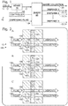
- a cell-containing solution 146 flows through a sample channel 148 arranged substantially parallel to a dispensing channel 150 containing a pressurized dispensing fluid 152.
- the respective liquids generally flow in the same direction as indicated by the arrows in the drawings.
- a connecting channel 154 fluidly connects sample channel 148 to dispensing channel 150.
- a sensing region 156 is disposed in sample channel 148 upstream of the connection between channel 148 and channel 154.
- connecting channel 154 is substantially perpendicular to channels 148 and 150. However, other transverse orientations may be suitable.
- This example describes a parallel channel paddle diverter suitable for use in an on-demand cell dispensing system 10; see Fig. 7 .
- Fig. 7 shows an exemplary diverter mechanism 200 for use in system 10 in a plan view.
- a cell-containing solution 202 flows through a sample channel 204 arranged substantially parallel to a dispensing channel 206 containing a dispensing fluid 208.
- the respective liquids generally flow in the same direction as indicated by the arrows in the drawings.
- a connecting channel 210 selectively connects sample channel 204 to dispensing channel 206 depending on the position of a rotary paddle 212.
- a sensing region 214 is disposed in sample channel 204 upstream of the connection between channel 204 and channel 210.
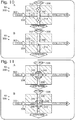
- Fig. 8 shows an exemplary diverter mechanism 230 for use in system 10 in a plan view.
- a cell-containing solution 232 flows through a sample channel 234 arranged substantially parallel to a dispensing channel 236 containing a dispensing fluid 238.
- the respective liquids generally flow in the same direction as indicated by the arrows in the drawings.
- a connecting channel 240 connects sample channel 234 to dispensing channel 236.
- a sensing region 242 is disposed in sample channel 234 upstream of the connection between channel 234 and channel 240.
- chamber 248 may be depressurized to reset diverter 230 for a subsequent diversion event.
- a second sensing region may be disposed downstream of the diverter in dispensing channel 236 to confirm that the particle was indeed diverted successfully.
- the diverter mechanism urges particles in desired directions using DEP.
- Multiple electrodes 274 adjacent to sample channel 264 are configured to create non-uniform electrical fields across the channel. Because of the DEP effect, these fields will exert a net force on a neutral body such as a cell, causing the body to move transversely within the channel. Accordingly, the electrodes are configured to generate a first field 276 such that all passing particles are moved to a near side 278 of the sample channel as shown in Fig. 9A .
- the controller causes a temporary second field 280 to be generated, thereby moving that particle to an opposite side 282 of the channel, as shown in Fig. 9B .
- Channels 264, 266, and 270 are configured such that particles on opposite side 282 of the channel are directed through the connecting channel and into the dispensing channel, while particles on near side 278 continue through the sample channel to the waste collection area.
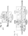
- Figs. 10A and 10B show an exemplary diverter mechanism 300 for use in system 10 in an overhead plan view.
- a cell-containing solution 302 flows through a sample channel 304 arranged transverse to a dispensing channel 306.
- Dispensing channel 306 contains a dispensing fluid 308 pressurized to a greater pressure than solution 302.
- the respective liquids are configured to generally flow in transverse directions as indicated by the arrows in the drawings.
- a sensing region 310 is disposed in sample channel 304 upstream of the connection between channel 304 and channel 306.
- solution 302 is prevented from interacting with fluid 308 by one or more valves such as inlet valve 312 and outlet valve 314.
- Valves 312 and 314 are normally closed, as indicated by the solid circles containing an "X" in Fig. 10A .
- Open valves are indicated by an open phantom circle. This valve position convention is used throughout the drawings.
- This example describes a crossed-channel rotary diverter suitable for use in an on-demand cell dispensing system 10; see Figs. 11A and 11B .
- a sensing region 344 may be disposed at any suitable location sufficient to detect a particle of interest 346 and allow rotary diverter 340 to divert the particle by rotating. In some examples, sensing region 344 may be located upstream of the rotary diverter. In this example, sensing region 344 is located at the rotary diverter, and the system is configured to be capable of diverting particle 346 after the particle is detected within diverter channel 342.
- rotary diverter 340 is oriented such that diverter channel 342 is aligned with and connects the sections of sample channel 334 as shown in Fig. 11A .
- Solution 332 and particles that do not meet the preselected criteria are passed through channel 342 to the collection area.
- the controller causes an actuator to reposition the rotary diverter to align diverter channel 342 with the sections of dispensing channel 336 as shown in Fig. 11B .
- This action causes a bulk of solution 348, along with particle 346, to be placed in line with the flow of dispensing fluid 338 and carried to the dispensing area.
- the controller After a suitable time or upon confirmation that particle 346 has been successfully diverted, the controller causes the actuator to reposition rotary diverter 340 to again align diverter channel 342 with sample channel 334 in preparation for a subsequent diversion event.
- Dispensing channel 366 also includes a branched section 370 in which channel 366 forks into two symmetrical channels 372 and 374, both of which are connected to sample channel 364.
- the respective liquids are configured to generally flow in the transverse directions as indicated by the arrows in the drawings.
- Dispensing fluid travelling down the second branch then intersects upstream of the blocked particle and flushes (e.g., carries or pushes) it through dispensing channel 398, along with a surrounding portion of the sample-containing carrier fluid.
- one or more valves or other control mechanisms for dispensing fluid may be located off-chip.
- diverter mechanism 384 may include no moving parts, and may be manufactured using conventional injection molding methods.
- Diversion fluid channel 388, branch 386, and dispensing channel 398 may all be substantially aligned directionally at a right angle to sheathed sample channel 392. In other examples, various other angles and arrangements may be suitable.
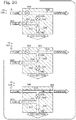
- Fig. 16 shows another embodiment of this Example 8 in the form of diverter mechanism 430, which is substantially identical to diverter mechanism 400 of Fig. 15 .
- diverter mechanism 430 includes two sensing regions and two dispensing channels, allowing the system to be used as a sorting device.
- a first sensing region 432 is disposed along a sample channel 434 in series with a second sensing region 436.
- the two sensing regions may be configured with different parameters to detect particles having different characteristics.
- the two sensing regions may be configured with different sensing modalities.
- a particle of interest 446 is detected by first sensing region 432 and meets a first set of criteria
- the controller may respond by opening a valve 448 in second dispensing channel 440, thereby diverting particle 446 to dispense through nozzle channel 444.
- a second particle meeting a second set of criteria may be detected by second sensing region 436 and sorted to a different destination by opening a valve 450 in first dispensing channel 438.
- more than two sensing regions and/or more than two dispensing channels may be included.
- a single dispensing channel may be used in conjunction with a movable substrate that is repositioned to sort into different wells or locations based on the detected particle characteristics.
- a single sensing region may be configured to distinguish between particles meeting multiple sets of criteria.
- the controller may then confine and direct particle 464 using any one of a combination of the pressure sources and pathways created by the independent channels 462. Various combinations may be utilized to maximize efficiency, speed, and/or to manipulate particles of differing characteristics. Particle 464 may be dispensed via nozzle 468 or sent to some other destination (not shown).
- Fig. 19 shows another embodiment of this Example 8 including a diverter mechanism 500 substantially identical to diverter mechanism 400.
- This embodiment illustrates one method for hydrodynamically focusing a solution channel 502 by introducing a sheathing liquid.
- the pressurized sheath liquid is introduced at an inlet port 504, and travels via sheathing channels 506 and 508 before intersecting with channel 502 to surround the solution contained in that channel.
- the flow of liquid may enter an unsheathing area.
- side channels 510 and 512 split off the outer flow of liquid from central channel 514, which then includes the original solution minus any dispensed volume. Unsheathing may be desirable to reduce the dilution of collected waste flow.
- Figs. 20A-20C show an exemplary diverter mechanism 530 for use in system 10.
- Diverter mechanism 530 includes a pressurized cell-containing solution 532 in a sample channel 534.
- Sample channel 534 is connected via a valved connecting channel 536 with a selectively pressurizable dispensing channel 538, and via a valved collection channel 540 with a collection area.
- a sensing region 542 is disposed adjacent to sample channel 534 upstream of the connection between channel 534 and the other channels.
- a collection valve 544 is located in collection channel 540; a connection valve 546 is located in connecting channel 536; and a pressure source valve 548 is located in dispensing channel 538. As shown in Fig. 20A , collection valve 544 is normally open and the other two valves are normally closed to cause solution 532 to flow to the collection area.
- the controller When a particle of interest 550 is detected in sensing region 542, the controller responds by closing collection valve 544 and opening connection valve 546 to open a path to dispensing channel 538 as shown in Fig. 20B . Shortly thereafter, pressure source valve 548 is opened as shown in Fig. 20C to pressurize channel 538 and flush particle 550 to the dispensing area. Connection valve 546 is closed at the same time to prevent backflow toward the sample channel and collection area. After a suitable delay, or upon confirmation that particle 550 was in fact diverted, the three valves are repositioned as needed to their original states in preparation for a subsequent diversion event.
- Figs. 21A-21B show an exemplary diverter mechanism 560 for use in system 10.
- Diverter mechanism 560 is similar to diverter mechanism 530. However, in this embodiment, four valves are used rather than three. This avoids the situation of the previous embodiment in which the connection valve had to be closed to prevent backflow. Here, the four valves are operated in pairs to isolate and flush a particle.
- valves 566 and 568 in sample channel 562 are normally open, and valves 574 and 576 in the dispensing channels are normally closed as shown in Fig. 21A .
- the controller closes valves 566 and 568 to isolate the particle and opens valves 574 and 576 to flush the particle through dispensing fluid outlet channel 572 as shown in Fig. 21B .
- Figs. 22A and 22B show an exemplary diverter mechanism 600 for use in system 10.
- Diverter mechanism 600 includes a sample channel 602 intersected by sheath flow channels 604 and 606 similar to those described above with respect to Fig. 18 .
- a particle of interest 608 detected at a sensing region 610 is diverted by simply closing off a collection fork 612 of channel 602 to redirect the particle to a dispensing fork 614 of channel 602 as shown in Fig. 22B .
- No additional pressure source in the form of dispensing fluid is used.
- a valve 616 is used to close off collection fork 612.
- a valve may be included in the dispensing fork.
- a toggle valve may be used to selectively close and open the two forks simultaneously.
- Fig. 23 is a schematic diagram showing an illustrative system 700 which is an example of system 10.
- System 700 includes a microfluidics chip 702 on which is located a system including the channels and one or more diverter mechanisms described above.
- Various devices such as valves, sliders, vacuum chambers, and other components that may be located on chip 702 are caused to operate by actuators 704 such as solenoid valves.
- actuators 704 are in turn activated by switches 706 controlled through an input/output (I/O) system 708 by a processor 710.
- Processor 710 may include a microprocessor such as the processor of a typical personal computer or similar device, and may be in communication with a memory or storage device containing instructions for the processor to carry out.
- the controller described above may include the combination of processor 710 and the storage device.
- Processor 710 receives input from sensors 712, such as a camera system or other detection device used in a sensing region on the chip.
- Chip 702 may be mounted on or associated with an X-Y stage 714 such that the chip or a substrate onto which the chip dispenses particles can be precisely located and repositioned as desired.
Description
- The ability to perform molecular and cellular analyses of biological systems has grown explosively over the past several decades. In particular, the advent and refinement of molecular and cellular techniques, such as DNA sequencing, gene cloning, monoclonal antibody production, cell transfection, amplification techniques (such as PCR), and transgenic animal formation, have fueled this explosive growth. These techniques have spawned an overwhelming number of identified genes, encoded proteins, engineered cell types, and assays for studying these genes, proteins, and cell types. Unfortunately, as the number of possible combinations of samples, reagents, and assays becomes nearly incalculable, it has become increasingly apparent that novel approaches are necessary even to begin to make sense of this complexity, especially within reasonable temporal and monetary limitations.
- One approach to these difficulties has been to reduce the scale of assays, focusing on small volumes and small numbers of particles, including individual cells. The traditional method for dispensing a single cell (or other particle) for analysis is through dilution. Specifically, a solution containing the cells is diluted to a concentration such that each absorption/dispensing of pipette contains on average a single cell. However, this method is not accurate: aliquots may contain no cell, one cell, or multiple cells. Single cells also may be dispensed by pick-and-place robot systems, which locate an individual cell (for example, on a dish), pick up the cell, and place the cell at another location. However, pick-and-place systems need to locate each cell and require significant time if moving a substantial number of cells. Single cells also may be analyzed using flow cytometry, but this method is complex and expensive, and not set up for or intended to dispense single cells.
-
WO2010/144814 discloses a method for sorting particles using fluid streams and valves, wherein a particle is introduced in a microfluidic sample channel thus directing a diverting fluid into the sample channel downstream the particle, then the particle is captured by a motive force field (e.g. optical trapping, magnetic or electrophoretic) and located at one end of the sample channel, where the particle is flushed by a diverting fluid flowed into the sample channel upstream the particle. Valves are used to avoid crosstalk between the channels. -
EP 2 153 898 - Thus, in view of these shortcomings, there is a need for methods that can effectively manipulate individual cells and other small particles, such as beads, in small volumes.
- The invention provides methods for the isolation of particles, such as cells and/or beads from a fluid sample.
- Features, functions, and advantages may be achieved independently in various embodiments of the present disclosure, or may be combined in yet other embodiments, further details of which can be seen with reference to the following description and drawings.
-
-
Figures 2-11 and20-22 show embodiments not falling within the scope of the claims and are for illustrative purpose. -
Fig. 1 is a schematic diagram showing an illustrative on-demand cell dispensing system according to the present disclosure. -
Figs. 2A, 2B, and 2C show a plan view of an illustrative diverter mechanism suitable for use in the system shown inFig. 1 , depicting three different positions of a sliding diverter. -
Fig. 3 is a plan view of another illustrative diverter mechanism suitable for use in the system shown inFig. 1 , including a vacuum-actuated flexible membrane. -
Fig. 4 is a sectional elevation view of the diverter mechanism ofFig. 3 taken at line 4-4. -
Fig. 5 is a plan view of the diverter mechanism ofFig. 3 after actuation of the flexible membrane. -
Fig. 6 is a sectional elevation view of the diverter mechanism ofFig. 5 taken at line 6-6. -
Fig. 7 is a plan view of another illustrative diverter mechanism suitable for use in the system shown inFig. 1 , including a rotary paddle diverter. -
Fig. 8 is a plan view of another illustrative diverter mechanism suitable for use in the system shown inFig. 1 , including a pressure-actuated flexible membrane. -
Figs. 9A and 9B show a plan view of another illustrative diverter mechanism suitable for use in the system shown inFig. 1 , including a dielectrophoresis (DEP) diverter and showing two states of the diverter. -
Figs. 10A and 10B show a plan view of another illustrative diverter mechanism suitable for use in the system shown inFig. 1 , including a crossed-channel valved diverter and showing the valves in a non-diverting and a diverting state. -
Figs. 11A and 11B show a plan view of another illustrative diverter mechanism suitable for use in the system shown inFig. 1 , including a rotary diverter configured to selectively connect channels and showing a non-diverting and a diverting state of the diverter. -
Figs. 12A and 12B show a plan view of another illustrative diverter mechanism suitable for use in the system shown inFig. 1 , including a branched dispensing fluid channel. -
Fig. 13 is a plan view of an alternative embodiment of the diverter mechanism ofFig. 12 . -
Fig. 14 shows another illustrative diverter mechanism suitable for use in the system ofFig. 1 , including two dispensing fluid branches. -
Fig. 15 shows another illustrative diverter mechanism suitable for use in the system shown inFig. 1 , including a branched dispensing fluid channel having a central leg and a nozzle section formed at a dispensing area. -
Fig. 16 shows another illustrative diverter mechanism suitable for use in the system shown inFig. 1 , including multiple sensing regions and multiple diverting areas. -
Fig. 17 shows another illustrative diverter mechanism suitable for use in the system shown inFig. 1 , including multiple parallel channels providing independent sources of pressurized dispensing fluid. -
Fig. 18 shows another illustrative diverter mechanism suitable for use in the system shown inFig. 1 , including a sorting arrangement. -
Fig. 19 shows another illustrative diverter mechanism suitable for use in the system shown inFig. 1 , including a sheathing and unsheathing channel arrangement for hydrodynamically focusing a cell sample. -
Figs. 20A, 20B, and 20C show another illustrative diverter mechanism suitable for use in the system shown inFig. 1 , including an offset-tee arrangement with three valves. -
Figs. 21A and 21B show another illustrative diverter mechanism suitable for use in the system shown inFig. 1 , including an offset-tee arrangement with four valves. -
Figs. 22A and 22B show another illustrative diverter mechanism suitable for use in the system shown inFig. 1 , including a forking sample channel. -
Fig. 23 shows an illustrative embodiment of the system shown inFig. 1 , including a control system and substrate positioning mechanism. - The invention provides methods for isolating particles, such as cells, viruses, organelles, beads, and/or vesicles from a fluid sample, the method comprising: streaming a fluid sample containing a particle through a microfluidic sample channel; detecting a characteristic of the particle as it passes through a detection zone of the sample channel; generating a diversion signal in response to the detected characteristic satisfying one or more selected criteria; and diverting the particle from the sample channel into an outlet channel by directing a diverting fluid into the sample channel upstream and downstream of the particle in response to the diversion signal, to substantially isolate the particle from the sample and flush the particle into the outlet channel.. This method allows the dispensing of particles more efficiently, reliably, precisely, and/or with more viability than was previously possible.
- Further aspects of the invention are described in the following sections: (I) overview of microfluidic systems, (II) physical structures of fluid networks, (III) particles, (IV) input mechanisms, (V) measurement and detection mechanisms, (VI) output mechanisms, (VII) overview of an on-demand dispensing system, and (VIII) examples.
- Particle manipulations may be performed in microfluidic systems such as those described in this disclosure. A microfluidic system generally comprises any system in which very small volumes of fluid are stored and manipulated, generally less than about 500 µl, typically less than about 100 µl, and more typically less than about 10 µl. Microfluidic systems carry fluid in predefined paths through one or more microfluidic passages. A microfluidic passage may have a minimum dimension, generally height or width, of less than about 200, 100, or 50 µm. Passages are described in more detail below in Section II.
- Microfluidic systems may include one or more sets of passages that interconnect to form a generally closed microfluidic network. Such a microfluidic network may include one, two, or more openings at network termini, or intermediate to the network, that interface with the external world. Such openings may receive, store, and/or dispense fluid. Dispensing fluid may be introduced directly into the microfluidic network or to sites external the microfluidic system. Such openings generally function in input and/or output mechanisms, described in more detail below, and may include reservoirs, also described in more detail below.
- Microfluidic systems also may include any other suitable features or mechanisms that contribute to fluid and/or particle manipulation. For example, microfluidic systems may include regulatory or control mechanisms that determine aspects of fluid flow rate and/or path. Valves and/or pumps that participate in such regulatory mechanisms are described in more detail below. Alternatively or additionally, microfluidic systems may include mechanisms that determine, regulate, and/or sense fluid temperature, fluid pressure, fluid flow rate, exposure to light, exposure to electric fields and/or magnetic field strength. Accordingly, microfluidic systems may include heaters, coolers, electrodes, lenses, gratings, light sources, pressure sensors, pressure transducers, microprocessors and/or microelectronics. Furthermore, each microfluidic system may include one or more features that act as a code to identify a given system. The features may include any detectable shape or symbol, or set of shapes or symbols, such as black-and-white or colored barcode, a word and/or a number, that has a distinctive position, identity, and/or other property (such as optical property).
- Microfluidic systems may be formed of any suitable material or combination of suitable materials. Suitable materials may include elastomers, such as polydimethylsiloxane (PDMS); plastics, such as polystyrene, polypropylene and polycarbonate.; glass; ceramics; sol-gels; silicon and/or other metalloids; metals or metal oxides; biological polymers, mixtures, and/or particles, such as proteins (gelatin, polylysine, serum albumin, collagen), nucleic acids and/or microorganisms.
- Microfluidic systems, also referred to as chips, may have any suitable structure. Such systems may be fabricated as a unitary structure from a single component, or as a multi-component structure of two or more components. The two or more components may have any suitable relative spatial relationship and may be attached to one another by any suitable bonding mechanism.
- In some embodiments, two or more of the components may be fabricated as relatively thin layers, which may be disposed face-to-face. The relatively thin layers may have distinct thickness, based on function. For example, the thickness of some layers may be 10 to 250 µm, 20 to 200 µm, or 50 to 150 µm. Other layers may be substantially thicker, in some cases providing mechanical strength to the system. The thicknesses of such other layers may be 0.25 to 2 cm, 0.4 to 1.5 cm, or 0.5 to 1 cm. One or more additional layers may be a substantially planar layer that functions as a substrate layer, in some cases contributing a floor portion to some or all microfluidic passages.
- Components of a microfluidic system may be fabricated by any suitable mechanism, based on the desired application for the system and on materials used in fabrication. For example, one or more components may be molded, stamped, and/or embossed using a suitable mold. Such a mold may be formed of any suitable material by micromachining, etching, soft lithography, material deposition, cutting, and/or punching. Alternatively, or in addition, components of a microfluidic system may be fabricated without a mold by etching, micromachining, cutting, punching, and/or material deposition.
- Microfluidic components may be fabricated separately, joined, and further modified as appropriate. For example, when fabricated as distinct layers, microfluidic components may be bonded, generally face-to-face. These separate components may be surface-treated, for example, with reactive chemicals to modify surface chemistry, with particle binding agents and/or with reagents to facilitate analysis. Such surface-treatment may be localized to discrete portions of the surface or may be relatively nonlocalized. In some embodiments, separate layers may be fabricated and then punched and/or cut to produce additional structure. Such punching and/or cutting may be performed before and/or after distinct components have been joined.
- Microfluidic systems may include any suitable structure(s) for the integrated manipulation of small volumes of fluid, including moving and/or storing fluid, and particles associated therewith. The structures may include passages, reservoirs, and/or regulators, among others.
- Passages generally comprise any suitable path, channel, or duct through, over, or along which materials (e.g., fluid, particles, and/or reagents) may pass in a microfluidic system. Collectively, a set of fluidically communicating passages, generally in the form of channels, may be referred to as a microfluidic network. In some cases, passages may be described as having surfaces that form a floor, a roof, and walls. Passages may have any suitable dimensions and geometry, including width, height, length, and/or cross-sectional profile, and may follow any suitable path, including linear, circular, and/or curvilinear. Passages also may have any suitable surface contours, including recesses, protrusions, and/or apertures, and may have any suitable surface chemistry or permeability at any appropriate position within a channel. Suitable surface chemistry may include surface modification, by addition and/or treatment with a chemical and/or reagent, before, during, and/or after passage formation.
- In some cases, passages, and particularly channels, may be described according to function. For example, passages may be described according to direction of material flow in a particular application, relationship to a particular reference structure, and/or type of material carried. Accordingly, passages may be inlet passages (or channels), which generally carry materials to a site, and outlet passages (or channels), which generally carry materials from a site. In addition, passages may be referred to as particle passages (or channels), reagent passages (or channels), focusing passages (or channels), perfusion passages (or channels) and/or waste passages (or channels).
- Passages may branch, join, and/or dead-end to form any suitable microfluidic network. Accordingly, passages may function in particle positioning, sorting, retention, treatment, detection, propagation, storage, mixing, and/or release. Further aspects of passages are included throughout this Detailed Description.
- Reservoirs generally comprise any suitable receptacle or chamber for storing materials (e.g., fluid, particles and/or reagents), before, during, between, and/or after processing operations (e.g., measurement and/or treatment). Reservoirs, also referred to as wells, may include input, intermediate, and/or output reservoirs. Input reservoirs may store materials (e.g., fluid, particles, and/or reagents) prior to inputting the materials to a microfluidic network(s) portion of a chip. By contrast, intermediate reservoirs may store materials during and/or between processing operations. Finally, output reservoirs may store materials prior to outputting from the chip, for example, to an external processor or waste, or prior to disposal of the chip.
- Regulators generally comprise any suitable mechanism for generating and/or regulating movement of materials (e.g., fluid, particles, and/or reagents). Suitable regulators may include valves, pumps, and/or electrodes. Regulators may operate by actively promoting flow and/or by restricting active or passive flow. Suitable functions mediated by regulators may include mixing, sorting and connection (or isolation) of fluidic networks.
- Microfluidic systems may be used to manipulate particles. A particle generally comprises any object that is small enough to be inputted and manipulated within a microfluidic network in association with fluid, but that is large enough to be distinguishable from the fluid. Particles, as used here, typically are microscopic or near-microscopic, and may have diameters of 0.005 to 100 µm, 0.1 to 50 µm, or 0.5 to 30 µm. Alternatively, or in addition, particles may have masses of 10-20 to 10-5 gr, 10-16 to 10-7 gr, or 10-14 to 10-8 gr. Exemplary particles may include cells, viruses, organelles, beads, and/or vesicles, and aggregates thereof, such as dimers and trimers.
- Cells, as used here, generally comprise any self-replicating, membrane-bounded biological entity, or any nonreplicating, membrane-bounded descendant thereof. Nonreplicating descendants may be senescent cells, terminally differentiated cells, cell chimeras, serum-starved cells, infected cells, nonreplicating mutants and anucleate cells.
- Cells used as particles in microfluidic systems may have any suitable origin, genetic background, state of health, state of fixation, membrane permeability, pretreatment, and/or population purity. Origin of cells may be eukaryotic, prokaryotic and archae, and may be from animals, plants, fungi, protists and/or bacteria. Cells may be wild-type; natural, chemical, or viral mutants and/or engineered mutants (such as transgenics). In addition, cells may be growing, quiescent, senescent, transformed, and/or immortalized, and cells may be fixed and/or unfixed. Living or dead, fixed or unfixed cells may have intact membranes, and/or permeabilized/disrupted membranes to allow uptake of ions, labels, dyes and ligands, or to allow release of cell contents. Cells may have been pretreated before introduction into a microfluidic system by any suitable processing steps. Such processing steps may include modulator treatment, transfection (including infection, injection, particle bombardment, lipofection and coprecipitate transfection), and/or processing with assay reagents, such as dyes or labels. Furthermore, cells may be a monoculture, generally derived as a clonal population from a single cell or a small set of very similar cells; may be presorted by any suitable mechanism such as affinity binding, FACS and drug selection; and/or may be a mixed or heterogeneous population of distinct cell types.
- Eukaryotic cells, that is, cells having one or more nuclei, or anucleate derivatives thereof, may be obtained from any suitable source, including primary cells, established cells, and/or patient samples. Such cells may be from any cell type or mixture of cell types, from any developmental stage, and/or from any genetic background. Furthermore, eukaryotic cells may be adherent and/or nonadherent. Such cells may be from any suitable eukaryotic organism including animals, plants, fungi, and/or protists.
- Eukaryotic cells may be from animals, that is, vertebrates or invertebrates. Vertebrates may include mammals, that is, primates (such as humans, apes and monkeys) or nonprimates (such as cows, horses, sheep, pigs, dogs, cats, marsupials and rodents). Nonmammalian vertebrates may include birds, reptiles, fish, (such as trout, salmon, goldfish and zebrafish), and/or amphibians (such as frogs of the species Xenopus and Rana). Invertebrates may include arthropods (such as arachnids and insects (e.g., Drosophila)), mollusks (such as clams and snails), annelids (such as earthworms), echinoderms (such as various starfish), coelenterates (such as jellyfish and coral), porifera (sponges), platyhelminths (tapeworms) and nemathelminths (flatworms).
- Eukaryotic cells may be from any suitable plant, such as monocotyledons, dicotyledons, gymnosperms, angiosperms, ferns, mosses, lichens, and/or algae. Exemplary plants may include plant crops (such as rice, corn, wheat, rye, barley and potatoes), plants used in research (e.g., Arabadopsis and loblolly pine) and plants of horticultural values (ornamental palms and roses).
- Eukaryotic cells may be from any suitable fungi, including members of the phyla Chytridiomycota, Zygomycota, Ascomycota, Basidiomycota, Deuteromycetes, and/or yeasts. Exemplary fungi may include Saccharomyces cerevisiae, Schizosaccharomyces pombe, Pichia pastoralis, Neurospora crassa, mushrooms, puffballs, imperfect fungi and molds.
- Eukaryotic cells may be from any suitable protists (protozoans), including amoebae, ciliates, flagellates, coccidia and microsporidia. Exemplary protists may include Giardia lamblia, Entamoeba. histolytica, Cryptosporidium, and/or N. fowleri.
- Particles may include eukaryotic cells that are primary, that is, taken directly from an organism or nature, without subsequent extended culture in vitro. For example, the cells may be obtained from a patient sample, such as whole blood, packed cells, white blood cells, urine, sputum, feces, mucus, spinal fluid, tumors, diseased tissue, bone marrow, lymph, semen, pleural fluid, a prenatal sample, an aspirate, a biopsy, disaggregated tissue, epidermal cells, keratinocytes, endothelial cells, smooth muscle cells, skeletal muscle cells, neural cells, renal cells, prostate cells, liver cells, stem cells and osteoblasts. Similar samples may be manipulated and analyzed from human volunteers, selected members of the human population, forensic samples, animals, plants, and/or natural sources (water, soil and air).
- Alternatively, or in addition, particles may include established eukaryotic cells. Such cells may be immortalized and/or transformed by any suitable treatment, including viral infection, nucleic acid transfection, chemical treatment, extended passage and selection and/or radiation exposure. Such established cells may include various lineages such as neuroblasts, neurons, fibroblasts, myoblasts, myotubes, chondroblasts, chondrocytes, osteoblasts, osteocytes, cardiocytes, smooth muscle cells, epithelial cells, keratinocytes, kidney cells, liver cells, lymphocytes, granulocytes, and/or macrophages. Exemplary established cell lines may include Rat-1, NIH 3T3, HEK 293, COS1, COS7, CV-1, C2C12, MDCK, PC12, SAOS, HeLa, Schneider cells, Junkat cells and SL2.
- Particles may be prokaryotic cells, that is, self-replicating, membrane-bounded microorganisms that lack membrane-bound organelles, or nonreplicating descendants thereof. Prokaryotic cells may be from any phyla, including Aquificae, Bacteroids, Chlorobia, Chrysogenetes, Cyanobacteria, Fibrobacter, Firmicutes, Flavobacteria, Fusobacteria, Proteobacteria, Sphingobacteria, Spirochaetes, Thermomicrobia, and/or Xenobacteria. Such bacteria may be gram-negative, gram-positive, harmful, beneficial, and/or pathogenic. Exemplary prokaryotic cells may include E. coli, S. typhimurium, B subtilis, S. aureus, C. perfringens, V. parahaemolyticus, and/or B. anthracis.
- Viruses may be manipulated as particles in microfluidic systems. Viruses generally comprise any microscopic/submicroscopic parasites of cells (animals, plants, fungi, protists, and/or bacteria) that include a protein and/or membrane coat and that are unable to replicate without a host cell. Viruses may include DNA viruses, RNA viruses, retroviruses, virions, viroids and prions. Exemplary viruses may include HIV, RSV, rabies, hepatitis virus, Epstein-Barr virus, rhinoviruses, bacteriophages, prions that cause various diseases (CJD (Creutzfeld-Jacob disease), kuru, GSS (Gerstmann-Straussler-Scheinker syndrome) and FFI (Fatal Familial Insomnia) and Alpers syndrome).
- Organelles may be manipulated in microfluidic systems. Organelles generally comprise any particulate component of a cell. For example, organelles may include nuclei, Golgi apparatus, lysosomes, endosomes, mitochondria, peroxisomes, endoplasmic reticulum, phagosomes, vacuoles and chloroplasts.
- Beads may be manipulated in microfluidic systems. Beads generally comprise any suitable manufactured particles. Beads may be manufactured from inorganic materials, or materials that are synthesized chemically, enzymatically and/or biologically. Furthermore, beads may have any suitable porosity and may be formed as a solid or as a gel. Suitable bead compositions may include plastics (e.g., polystyrene), dextrans, glass, ceramics, sol-gels, elastomers, silicon, metals, and/or biopolymers (proteins and nucleic acids). Beads may have any suitable particle diameter or range of diameters. Accordingly, beads may be a substantially uniform population with a narrow range of diameters, or beads may be a heterogeneous population with a broad range of diameters, or two or more distinct diameters.
- Beads may be associated with any suitable materials. The materials may include compounds, polymers, complexes, mixtures, phages, viruses, and/or cells. For example, the beads may be associated with a member of a specific binding pair (see Section VI), such as a receptor, a ligand, a nucleic acid and/or a member of a compound library. Beads may be a mixture of distinct beads, in some cases carrying distinct materials. The distinct beads may differ in any suitable aspect(s), such as size, shape, an associated code, and/or material carried by the beads. In some embodiments, the aspect may identify the associated material. Codes are described further below.
- Particles may be vesicles. Vesicles generally comprise any noncellularly derived particle that is defined by a lipid envelope. Vesicles may include any suitable components in their envelope or interior portions. Suitable components may include compounds, polymers, complexes, mixtures, aggregates, and/or particles. Exemplary components may include proteins, peptides, small compounds, drug candidates, receptors, nucleic acids and/or ligands.
- Microfluidic systems may include one or more input mechanisms that interface with the microfluidic network(s). An input mechanism generally comprises any suitable mechanism for inputting material(s) (e.g., particles, fluid, and/or reagents) to a microfluidic network of a microfluidic chip, including selective (that is, component-by-component) and/or bulk mechanisms.
- The input mechanism may receive material from internal sources, that is, reservoirs that are included in a microfluidic chip, and/or external sources, that is, reservoirs that are separate from, or external to, the chip.
- Input mechanisms that input materials from internal sources may use any suitable receptacle to store and dispense the materials. Suitable receptacles may include a void formed in the chip. Such voids may be directly accessible from outside the chip, for example, through a hole extending from fluidic communication with a fluid network to an external surface of the chip, such as the top surface. The receptacles may have a fluid capacity that is relatively large compared to the fluid capacity of the fluid network, so that they are not quickly exhausted. For example, the fluid capacity may be at least 1, 5, 10, 25, 50, or 100 µl. Accordingly, materials may be dispensed into the receptacles using standard laboratory equipment, if desired, such as micropipettes and syringes.
- Input mechanisms that input materials from external sources also may use any suitable receptacle and mechanism to store and dispense the materials. However, if the external sources input materials directly into the fluid network, the external sources may need to interface effectively with the fluid network, for example, using contact and/or noncontact dispensing mechanisms. Accordingly, input mechanisms from external sources may use capillaries or needles to direct fluid precisely into the fluid network. Alternatively, or in addition, input mechanisms from external sources may use a noncontact dispensing mechanism, such as "spitting," which may be comparable to the action of an inkjet printer. Furthermore, input mechanisms from external sources may use ballistic propulsion of particles, for example, as mediated by a gene gun.
- The inputting of materials into the microfluidics system may be facilitated and/or regulated using any suitable facilitating mechanism. Such facilitating mechanisms may include gravity flow, for example, when an input reservoir has greater height of fluid than an output reservoir. Facilitating mechanisms also may include positive pressure to push materials into the fluidic network, such as mechanical or gas pressure, or centrifugal force; negative pressure at an output mechanism to draw fluid toward the output mechanism; and/or a positioning mechanism acting within the fluid network. The positioning mechanism may include a pump and/or an electrokinetic mechanism.
- Particles manipulated by a microfluidic system may be analyzed by one or more measurement mechanisms at one or more measurement sites. The measurement mechanisms generally comprise any suitable apparatus or method for detecting a preselected particle or particle characteristic (provided, for example, by the particle, a particle component, and/or an assay product). The measurement sites generally comprise any suitable particle position or positions at which a measurement is performed, internal and/or external to the system.
- The measurement mechanism may employ any suitable detection method to analyze a sample, qualitatively and/or quantitatively. Suitable detection methods may include spectroscopic methods, electrical methods, hydrodynamic methods, imaging methods, and/or biological methods, especially those adapted or adaptable to the analysis of particles. These methods may involve detection of single or multiple values, time-dependent or time-independent (e.g., steady-state or endpoint) values, and/or averaged or (temporally and/or spatially) distributed values. These methods may measure and/or output analog and/or digital values.
- Spectroscopic methods generally may include detection of any property of light (or a wavelike particle), particularly properties that are changed via interaction with a sample. Suitable spectroscopic methods may include absorption, luminescence (including photoluminescence, chemiluminescence, and electrochemiluminescence), magnetic resonance (including nuclear and electron spin resonance), scattering (including light scattering, electron scattering, and neutron scattering), diffraction, circular dichroism, and optical rotation. Suitable photoluminescence methods may include fluorescence intensity (FLINT), fluorescence polarization (FP), fluorescence resonance energy transfer (FRET), fluorescence lifetime (FLT), total internal reflection fluorescence (TIRF), fluorescence correlation spectroscopy (FCS), fluorescence recovery after photobleaching (FRAP), fluorescence activated cell sorting (FACS), and their phosphorescence and other analogs.
- Electrical methods generally may include detection of any electrical parameter. Suitable electrical parameters may include current, voltage, resistance, impedance, capacitance, and/or power.
- Hydrodynamic methods generally may include detection of interactions between a particle (or a component or derivative thereof) and its neighbors (e.g., other particles), the solvent (including any matrix), and/or the microfluidic system, and may be used to characterize molecular size and/or shape, or to separate a sample into its components. Suitable hydrodynamic methods may include chromatography, sedimentation, viscometry, and electrophoresis.
- Imaging methods generally may include detection of spatially distributed signals, typically for visualizing a sample or its components, including optical microscopy and electron microscopy.
- Biological methods generally may include detection of some biological activity that is conducted, mediated, and/or influenced by the particle, typically using another method, as described above.
- The measurement mechanism may be used to detect particles and/or particle characteristics at any suitable detection site, internal and/or external to the microfluidic system.
- Suitable internal detection sites may include any site(s) in or on a microfluidic system (a chip). These sites may include channels, chambers, and/or traps, and portions thereof, and may be referred to herein as sensing regions. Particles or particle characteristics may be detected while the particles (or released components/assay products) are stationary or moving. Stationary particles may be encountered following particle retention, for example, cells growing in a cell chamber. Moving particles may be encountered before and/or after particle retention, or upon confinement to a region. In particular, particles may be moved past a detection site by any suitable positioning mechanism, for example, by fluid flow (flow-based detection).
- The measurement method may detect and/or monitor any suitable characteristic of a particle, directly and/or indirectly (e.g., via a reporter molecule). Suitable characteristics may include particle identity, number, concentration, position (absolute or relative), composition, structure, sequence, and/or activity. The detected characteristics may include molecular or supramolecular characteristics, such as the presence/absence, concentration, localization, structure/modification, conformation, morphology, activity, number, and/or movement of DNA, RNA, protein, enzyme, lipid, carbohydrate, ions, metabolites, organelles, added reagent (binding), and/or complexes thereof. The detected characteristics also may include cellular characteristics, such as any suitable cellular genotype or phenotype, including morphology, growth, apoptosis, necrosis, lysis, alive/dead, position in the cell cycle, activity of a signaling pathway, differentiation, transcriptional activity, substrate attachment, cell-cell interaction, translational activity, replication activity, transformation, heat shock response, motility, spreading, membrane integrity, and/or neurite outgrowth.
- Microfluidic systems may include one or more output mechanisms that interface with the microfluidic network(s). An output mechanism generally comprises any suitable mechanism for outputting material(s) (e.g., fluid, particles, and/or reagents) from a microfluidic system, or portions thereof, including selective and/or bulk mechanisms. The output mechanism may direct outputted material to any suitable location, such as an internal and/or external sink. A sink generally comprises any receptacle or other site for receiving outputted materials, for disposal (e.g., a waste site) or for further study or manipulation (e.g., a collection site). The outputting of materials from the microfluidics system may be facilitated and/or regulated using any suitable facilitating mechanism, such as sources of internal pressure and/or external vacuum. The output mechanism may include a selection mechanism, such as a filter, that selects outputted materials based on some criterion, such as whether the material is a particle or a fluid.
- This disclosure describes microfluidic methods and systems for on-demand dispensing of particles such as those described in Section III above. The terms "particle" and "cell" are used interchangeably herein to indicate any such object.
-
Fig. 1 shows a schematic view of an illustrative on-demandcell dispensing system 10. In some examples,system 10 may include a microfluidic chip configured to detect particles moving in a channel and to selectively dispense one or more of the detected particles, for example, onto a substrate or into a target vessel. In some examples, the microfluidic chip may be placeable into an instrument and may be disposable following use. The microfluidic chip may be configured to engage with a manifold in the instrument to establish fluidic connections and provide a source of liquid to the chip and system. -
System 10 may include a cell passage orchannel 12 configured to direct a moving and/orpressurized solution 14 containing one or more particles.Channel 12, and other channels discussed herein, may include any suitable structure configured as a microfluidic pathway for conducting a fluid, and may be any suitable shape or size as described above in Section II.Solution 14 may include particles in a buffer or other liquid, and may be hydrodynamically focused, such as by using a sheath fluid. -
System 10 may include asensing region 16 configured to detect the presence of a particle of interest inchannel 12 and to communicate that detection information to acontroller 18.Sensing region 16 may include any suitable detector and/or sensor configured to detect the presence of a particle meeting certain selected criteria. For example,sensing region 16 may include optical, electrical, electromagnetic, and/or chemical detectors. Various detection methods may be used, independently or in combination, such as forward- or side-scatter signals, impedance measurements (e.g., Coulter counters), ferrous particles, photomultiplier tube (PMT), and/or fluorescence activated cell sorting (FACS), and/or any other suitable detection and measuring method described above in Section V. -
System 10 may include one ormore sensing regions 16. For example, sensing regions may be arranged in series to detect particles not previously detected and removed fromchannel 12 or arranged in parallel to detect particles in multiple branches ofchannel 12. In some examples, additional sensing regions may be included in a destination channel or other suitable location to provide verification of expected particle relocation. -
Controller 18 may include any suitable electronic controller configured to receive detection information from sensingregion 16 and take selected actions in response to the information received. For example,controller 18 may include a microprocessor and a digital memory configured to store instructions carried out by the microprocessor in response to certain inputs. In some examples,controller 18 may respond to an input from sensingregion 16 indicating that a particle meeting predetermined criteria has been detected.Controller 18 may then initiate an output signal causing actuation of adiverter mechanism 20. -
Diverter mechanism 20 may include any suitable device configured to move the detected particle fromchannel 12 into a dispensing channel 22, which may contain or selectively contain apressurized dispensing fluid 24.Diverter mechanism 20 may include one or more active or passive mechanical components, motors, hydraulics, pneumatics, pressurized fluidics, vacuum generators, electrical or magnetic fields, thermal expansion and/or contraction and piezoelectric components. In some examples,diverter mechanism 20 may physically redirect a bulk of solution containing the particle. In some examples,diverter mechanism 20 may urge the particle into dispensing channel 22 through an interconnecting pathway. In some examples,diverter mechanism 20 may utilize valves or other suitable devices to control dispensingfluid 24, which may be used to confine, flush, and/or carry the particle into or through dispensing channel 22. - Undiverted particles and
solution 14 may continue to awaste collection area 26, while diverted particles,solution 14, and/or dispensingfluid 24 may be directed to a dispensing area 28.Waste collection area 26 may include a collection device such as a vial or container, or may be redirected to an input ofchannel 12 for additional particle diversion, or elsewhere for additional processing.Cell solution 14 may be reused as appropriate. - The diverter mechanism of
system 10 may divert a bulk of liquid surrounding the particle of interest into a dispensing area, for example, via a nozzle. This may facilitate a reduction in adverse effects due to manufacturing or operational tolerances on dispensing efficiency. Moreover, in this manner a dispensed cell or particle is kept in an aqueous environment, which may be critical to maintaining its health and/or structural integrity. - Dispensing area 28 may include any suitable location where a user wishes the particle or particles to be dispensed. For example, dispensing area 28 may include one or more locations on a substrate, or a target vessel. Moreover,
system 10 may includemultiple diverter mechanisms 20 and/or dispensing channels 22. Accordingly,system 10 may be configured as a sorting device in which cells are diverted and dispensed according to their sensed characteristics. -
System 10 may be mounted on a stable frame, preventing vibration which may affect performance. In some examples, a vessel such as a micro-well plate may be placed under a dispensing nozzle, so that dispensed liquid as well as particles rests at the bottom of the plate wells. The vessel may be placed on an X-Y stage in order to control the position of the wells with respect to the dispensing nozzle. Dispensing of multiple particles into the same position may be achieved by maintaining the substrate/vessel in place. The system preferably includes mounting features, such as holes or apertures, allowing it to be easily positioned in a dedicated instrument. An assembled system may include a microfluidic chip which is sealed by means of a laminate and a manifold on which a valve is mounted. Generally, the manifold assembly is a permanent piece and the chip assembly may be either disposable or washable. The manifold may contain a valve for providing pressurized liquid to the chip on demand. In order to provide the required liquid or buffers to the chip, the manifold assembly may engage with the chip and seal by means such as o-rings, a flexible gasket, and/or surface-to-surface contact. - This section describes selected embodiments of the present disclosure related to on-demand cell dispensing devices. The features disclosed in this section may be combined with each other and with features disclosed in other sections. The embodiments shown in
Figures 2-11 and20-22 do not fall within the scope of the claims and are for illustrative purpose. - This example describes a parallel channel sliding diverter suitable for use in an on-demand
cell dispensing system 10; seeFigs. 2A-2C . -
Figs. 2A-2C show three successive overhead views of anexemplary diverter mechanism 100 for use insystem 10. In this example, acell sample channel 102 containing a solution ofsample cells 104 is arranged substantially parallel to a dispensingchannel 106 containing apressurized dispensing fluid 108. The respective liquids generally flow in the same direction as indicated by the arrows in the drawings. Amulti-aperture slide diverter 110 is disposed transverse to the twochannels first aperture 112 is normally in line withsample channel 102 and asecond aperture 114 is normally in line with dispensingchannel 106, as shown inFig. 2A . Asensing region 116 is positioned adjacent to or withinsample channel 102, upstream ofdiverter 110. - A sensor in
sensing region 116 may be configured to signal the controller (not shown) when a particle ofinterest 118 is detected. In response to the sensed particle of interest, the controller then repositions diverter 110 as shown inFigs. 2B and 2C , by causing the diverter to travel alongdiverter way 120 such that, in the position shown inFig. 2C ,aperture 112 aligns with dispensingchannel 106 rather thansample channel 102. - Depending on the distance between the sensing region and
aperture 112, as well as other factors such as expected or measured particle speed, the controller repositionsdiverter 108 when particle ofinterest 118 is expected to be withinaperture 112. Accordingly, repositioning the diverter causesparticle 118 and a bulk of surrounding liquid 122 to be placed into the flow of dispensingchannel 106. - After a delay sufficient to allow
particle 118 to be carried out ofaperture 112 by the flow of dispensingfluid 108,diverter 110 is repositioned back to the original position, aligningaperture 112 withsample channel 102 andaperture 114 with dispensingchannel 106. This action may be initiated, for example, by the controller, or may be caused by a delay built into the diverter or an actuating mechanism of the diverter. The actuating mechanism in this example may include one or more electromagnets controllable by the controller for urgingdiverter 110 alongway 120. -
Diverter 110 may include one or more additional apertures. For example, a third aperture (not shown) may be configured to align withsample channel 102 whendiverter 110 is in the position shown inFig. 2C . This additional aperture would allowsolution 104 insample channel 102 to continue flowing whileparticle 118 is being diverted. This may be desirable, for example, if multiple slide diverters are arranged in series, to continue selecting or sorting additional particles whileparticle 118 is diverted. - In some embodiments of this example, one or more additional sensing regions may be included. For example, an additional sensing region may be included for verifying that
particle 118 was in fact present inaperture 112, and/or thatparticle 118 passed into dispensingchannel 106 following diversion. - This example describes a parallel channel vacuum diverter suitable for use in an on-demand
cell dispensing system 10; seeFigs. 3-6 . -
Figs. 3-6 show anexemplary diverter mechanism 140 for use insystem 10.Fig. 3 shows a plan view ofdiverter 140 in anormal operating mode 142, andFig. 4 shows a sectional side view taken along line 4-4 with the mechanism in the same position.Figs. 5 and 6 , respectively, show corresponding views ofdiverter 140 in a particle-diverting mode 144. - In this example, a cell-containing
solution 146 flows through asample channel 148 arranged substantially parallel to a dispensingchannel 150 containing apressurized dispensing fluid 152. The respective liquids generally flow in the same direction as indicated by the arrows in the drawings. A connectingchannel 154 fluidly connectssample channel 148 to dispensingchannel 150. Asensing region 156 is disposed insample channel 148 upstream of the connection betweenchannel 148 andchannel 154. In the example shown in the drawings, connectingchannel 154 is substantially perpendicular tochannels -
Mechanism 140 includes aflexible membrane 158 covering anunderlying vacuum chamber 160 in dispensingchannel 150 near the junction ofchannel 150 and connectingchannel 154. During normal operation,membrane 158 conforms to and forms a part of the wall ofchannel 150 as indicated inFigs. 3 and 4 . Relative operating pressures in the respective channels keepcell solution 146 from entering dispensingchannel 150. - As shown in
Figs. 5 and 6 , when a particle ofinterest 162 is detected insensing region 156, the controller responds by drawing a vacuum invacuum chamber 160, causingflexible membrane 158 to deform. This deformation causes a drop in pressure in the region ofmembrane 158 below the operating pressure ofcell solution 146, resulting in a pressure differential across the length of connectingchannel 154. Accordingly,particle 162 is drawn across the connecting channel into the flow of the dispensing channel. - After a suitable time has passed, or in response to a confirmation signal indicating a successful diversion of the particle, the controller releases the vacuum in
chamber 160, causingmembrane 158 to return to the normal operating position ofmode 142. This in turn causes pressures to return to normal, if they have not yet equilibrated, and prepares the diverter for the next particle to be diverted. - This example describes a parallel channel paddle diverter suitable for use in an on-demand
cell dispensing system 10; seeFig. 7 . -
Fig. 7 shows an exemplary diverter mechanism 200 for use insystem 10 in a plan view. In this example, a cell-containingsolution 202 flows through asample channel 204 arranged substantially parallel to a dispensingchannel 206 containing a dispensingfluid 208. The respective liquids generally flow in the same direction as indicated by the arrows in the drawings. A connecting channel 210 selectively connectssample channel 204 to dispensingchannel 206 depending on the position of arotary paddle 212. Asensing region 214 is disposed insample channel 204 upstream of the connection betweenchannel 204 and channel 210. - When a particle of interest 216 is detected in
sensing region 214, the controller responds by repositioningpaddle 212 from its original position shown in solid lines to a diverting position shown in phantom lines inFig. 7 . This diverting position directs the flow fromsample channel 204 across channel 210 and into dispensingchannel 206. Pressures and flow rates may be controlled such that dispensingfluid 208 does not resist the entry of the particle and solution into the dispensing channel. - After a suitable amount of time,
paddle 212 may be repositioned to its original state to reset diverter 200 for a subsequent diversion event. In some examples, a second sensing region may be disposed downstream of the diverter in dispensingchannel 206 to confirm that the particle was indeed diverted successfully. In some examples, this confirmation may be a signal to the controller indicating that the paddle may be safely reset. - This example describes a parallel channel blocking diverter suitable for use in an on-demand
cell dispensing system 10; seeFig. 8 . -
Fig. 8 shows anexemplary diverter mechanism 230 for use insystem 10 in a plan view. In this example, a cell-containingsolution 232 flows through asample channel 234 arranged substantially parallel to a dispensingchannel 236 containing a dispensingfluid 238. The respective liquids generally flow in the same direction as indicated by the arrows in the drawings. A connectingchannel 240 connectssample channel 234 to dispensingchannel 236. Asensing region 242 is disposed insample channel 234 upstream of the connection betweenchannel 234 andchannel 240. - A blocking
device 244 is disposed adjacent to samplechannel 234 downstream of the connection betweenchannel 234 and connectingchannel 240. In this example, blockingdevice 244 includes aflexible membrane 246 and apressure chamber 248. However, blockingdevice 244 may include other mechanisms, such as a sliding block or a valve, and in general may include any suitable device configured to selectively block or restrict flow inchannel 234. - When a particle of
interest 250 is detected insensing region 242, the controller responds by pressurizingchamber 248, causingmembrane 246 to flex intochannel 234 as shown in phantom lines inFig. 8 , thereby blocking flow in the channel. With the sample channel blocked, the flow ofsolution including particle 250 is directed fromsample channel 234 across connectingchannel 240 and into dispensingchannel 236. Pressures and flow rates may be controlled such that dispensingfluid 238 does not resist the entry of the particle and solution into the dispensing channel. - After a suitable amount of time, or in response to a confirmation that diversion was successful,
chamber 248 may be depressurized to resetdiverter 230 for a subsequent diversion event. As in some other examples described above, a second sensing region may be disposed downstream of the diverter in dispensingchannel 236 to confirm that the particle was indeed diverted successfully. - This example describes a parallel channel dielectrophoresis (DEP) diverter suitable for use in an on-demand
cell dispensing system 10; seeFigs. 9A and 9B . -
Figs. 9A and 9B show anexemplary diverter mechanism 260 for use insystem 10 in a plan view. In this example, a cell-containingsolution 262 flows through asample channel 264 arranged substantially parallel to a dispensingchannel 266 containing a dispensingfluid 268. The respective liquids generally flow in the same direction as indicated by the arrows in the drawings. A connectingchannel 270 connectssample channel 264 to dispensingchannel 266. Asensing region 272 is disposed insample channel 264 upstream of the connection betweenchannel 264 andchannel 270. - In this example, rather than redirecting flow, the diverter mechanism urges particles in desired directions using DEP.
Multiple electrodes 274 adjacent to samplechannel 264 are configured to create non-uniform electrical fields across the channel. Because of the DEP effect, these fields will exert a net force on a neutral body such as a cell, causing the body to move transversely within the channel. Accordingly, the electrodes are configured to generate afirst field 276 such that all passing particles are moved to anear side 278 of the sample channel as shown inFig. 9A . When a particle of interest is detected insensing region 272, the controller causes a temporarysecond field 280 to be generated, thereby moving that particle to anopposite side 282 of the channel, as shown inFig. 9B .Channels opposite side 282 of the channel are directed through the connecting channel and into the dispensing channel, while particles onnear side 278 continue through the sample channel to the waste collection area. - This example describes a crossed-channel valved diverter suitable for use in an on-demand
cell dispensing system 10; seeFigs. 10A and 10B . -
Figs. 10A and 10B show anexemplary diverter mechanism 300 for use insystem 10 in an overhead plan view. In this example, a cell-containingsolution 302 flows through asample channel 304 arranged transverse to a dispensingchannel 306.Dispensing channel 306 contains a dispensingfluid 308 pressurized to a greater pressure thansolution 302. The respective liquids are configured to generally flow in transverse directions as indicated by the arrows in the drawings. Asensing region 310 is disposed insample channel 304 upstream of the connection betweenchannel 304 andchannel 306. In normal operation,solution 302 is prevented from interacting withfluid 308 by one or more valves such asinlet valve 312 andoutlet valve 314.Valves Fig. 10A . Open valves are indicated by an open phantom circle. This valve position convention is used throughout the drawings. - When a particle of interest 316 is detected in
sensing region 310, the controller opensvalves Fig. 10B . Opening these valves causes the higher pressure dispensing fluid to reach the junction between the two channels while particle 316 is present, thereby diverting the particle down the dispensing channel. After a suitable amount of time, and/or upon confirmation that particle 316 has been successfully diverted,valves - This example describes a crossed-channel rotary diverter suitable for use in an on-demand
cell dispensing system 10; seeFigs. 11A and 11B . -
Figs. 11A and 11B show anexemplary diverter mechanism 330 for use insystem 10 in an overhead plan view. In this example, a cell-containingsolution 332 flows through asample channel 334 arranged transverse to a dispensingchannel 336.Dispensing channel 336 contains a dispensingfluid 338 pressurized to a greater pressure thansolution 332. The respective liquids are configured to generally flow in transverse directions as indicated by the arrows in the drawings. -
Diverter 330 includes arotary diverter 340 located at the junction ofchannels diverter channel 342 of the rotary diverter selectively connects the respective sections of eitherchannel 334 orchannel 336, depending on the rotational position ofrotary diverter 340. - A
sensing region 344 may be disposed at any suitable location sufficient to detect a particle ofinterest 346 and allowrotary diverter 340 to divert the particle by rotating. In some examples,sensing region 344 may be located upstream of the rotary diverter. In this example,sensing region 344 is located at the rotary diverter, and the system is configured to be capable of divertingparticle 346 after the particle is detected withindiverter channel 342. - In normal operation,
rotary diverter 340 is oriented such thatdiverter channel 342 is aligned with and connects the sections ofsample channel 334 as shown inFig. 11A .Solution 332 and particles that do not meet the preselected criteria are passed throughchannel 342 to the collection area. When a particle of interest such asparticle 346 is detected insensing region 344, the controller causes an actuator to reposition the rotary diverter to aligndiverter channel 342 with the sections of dispensingchannel 336 as shown inFig. 11B . This action causes a bulk ofsolution 348, along withparticle 346, to be placed in line with the flow of dispensingfluid 338 and carried to the dispensing area. - After a suitable time or upon confirmation that
particle 346 has been successfully diverted, the controller causes the actuator to repositionrotary diverter 340 to again aligndiverter channel 342 withsample channel 334 in preparation for a subsequent diversion event. - This example describes various crossed multi-channel diverters suitable for use in an on-demand
cell dispensing system 10; seeFigs. 12-18 . -
Figs. 12A and 12B show anexemplary diverter mechanism 360 for use insystem 10 in an overhead plan view. In this example, a cell-containingsolution 362 flows through asample channel 364 arranged transverse to a dispensingchannel 366.Solution 362 may be pressurized in a typical range from about 0.1 to about 1 psi, depending on desired flow rate. Other pressures may also be suitable.Dispensing channel 366 contains a dispensingfluid 368 pressurized to a greater pressure thansolution 362. Typically, the pressure of the dispensing fluid may be from about 1 to about 5 psi.Dispensing channel 366 also includes abranched section 370 in which channel 366 forks into twosymmetrical channels channel 364. The respective liquids are configured to generally flow in the transverse directions as indicated by the arrows in the drawings. - A
sensing region 376 is disposed insample channel 364 upstream of the connection betweenbranched section 370 andchannel 364. In normal operation,fluid 368 is prevented from interacting withsolution 362 by one or more valves such asinlet valve 378 andoutlet valve 380. In other examples, channels 372' and 374' in branched section 370' may each include abranch inlet valve 381, as shown in diverter mechanism 360' ofFig. 13 .Valves Fig. 12A . - In normal operation, flow proceeds down
sample channel 364, andsolution 362 is directed to the collection area along with any particles that do not meet predetermined criteria. When a particle ofinterest 382 is detected insensing region 376, the controller responds by openingvalves channel 366 as shown inFig. 12B . Becausechannels branched section 370 are symmetrical, a substantially equivalent flow passes through each of the branches, enteringsample channel 364 on opposite sides ofparticle 382. This effectivelyconfines particle 382 and then flushes it down dispensingchannel 366 throughoutlet valve 380. The overall width ofbranched section 370 is configured to minimize the effect of typical manufacturing variation in channel dimensions and other tolerance issues on confining efficiency. - After a suitable time or upon confirmation that
particle 382 has been successfully diverted, the controller closes the inlet and outlet valves in preparation for a subsequent diversion event. -
Fig. 14 shows another embodiment of a branched diverter mechanism similar todiverter mechanism 360. In this embodiment, however, adiverter mechanism 384 includes two branches of unequal length.First branch 386 may be in line with a dispensingfluid channel 388, andsecond branch 390 may branch from the dispensing channel to take a more circuitous route before intersecting asample channel 392 upstream of the first branch. In this embodiment, a dispensingfluid 394 may be released to pressurizebranches particle 396 travelling throughchannel 392. -
Branches branch 390 is substantially shorter than a path throughbranch 386, and in whichbranch 390 terminates at an intersection withchannel 392 upstream and spaced from the intersection ofbranch 386 withchannel 392. In this embodiment,branch 386 is configured as a straight path continuing in the direction of the long axis ofchannel 388.Branch 390 splits fromchannel 388 at a ninety-degree (or similar) angle, turning again after a certain distance to run parallel to branch 386 and intersect withchannel 392. Accordingly,branch 390 forms a substantially longer path thanbranch 386. - Because the branches are of unequal length and substantially identical cross-section, fluid travelling down
first branch 386 will reach an intersection withchannel 392 before fluid travelling downsecond branch 390. Accordingly, flow insample channel 392 will be effectively blocked by the incoming flow from first branch 386 (which will continue through the intersection and on through a dispensing channel 398). This action blocks the particle from proceeding to collection. - Dispensing fluid travelling down the second branch then intersects upstream of the blocked particle and flushes (e.g., carries or pushes) it through dispensing
channel 398, along with a surrounding portion of the sample-containing carrier fluid. In this embodiment (among others), one or more valves or other control mechanisms for dispensing fluid may be located off-chip. In other words,diverter mechanism 384 may include no moving parts, and may be manufactured using conventional injection molding methods. -
Diversion fluid channel 388,branch 386, and dispensingchannel 398 may all be substantially aligned directionally at a right angle to sheathedsample channel 392. In other examples, various other angles and arrangements may be suitable. -
Fig. 15 shows an embodiment of this Example 8 in the form ofdiverter mechanism 400, which is substantially similar todiverter mechanism 360 but with additional features. As indiverter mechanism 360, a cell-containingsolution 402 flows through asample channel 404 arranged transverse to a dispensing channel 406. Dispensing channel 406 contains a dispensingfluid 408 pressurized to a greater pressure thansolution 402. Dispensing channel 406 also includes abranched section 410. However, in this embodiment, channel 406 forks into twosymmetrical side channels channel 404. The respective liquids are configured to generally flow in the transverse directions as indicated by the arrows in the drawings. - A
sensing region 418 is disposed insample channel 404 upstream of the connection betweenbranched section 410 andchannel 404. As in the embodiment ofFigs. 12A and 12B ,fluid 408 is normally prevented from interacting withsolution 402 by one or more normally closed valves such asinlet valve 420. However, the embodiment ofFig. 15 does not include an outlet valve. Instead, anozzle section 422 is formed in a distal end of dispensing channel 406 by narrowing the channel. This narrowing is configured to allow capillary action to resist leakage via the nozzle section during normal operation. A hydrophobic material may be added tonozzle section 422, such as by applying a coating, to further enhance this resistance. - Operation of the embodiment of
Fig. 15 is similar to that ofFigs. 12A and 12B . However, two main differences exist during a diversion event. First, whenvalve 420 is opened,fluid 408 will flow through central channel 416 in addition to the side channels (412 and 414). Central channel 416 has a smaller cross section than the side channels, and therefore will allow a lower flow rate. This results in the confinement of a particle of interest 424 by the flows from the side channels as described above, but here includes an additional central flushing flow from the outlet of central channel 416. This may increase flushing efficiency and reduce dead zones. - Secondly, this embodiment does not include an outlet valve, instead relying on the capillary action of the nozzle section. Other embodiments may rely on the same functionality. When a diversion occurs, the pressure from the dispensing fluid released into the dispensing channel will overcome the capillary action and any hydrophobic coating, and dispense the particle through
nozzle section 422. Accordingly, dispensing may occur only at pressures above a certain threshold, for example, above about 1 psi. This results in a reduction in manufacturing costs by eliminating a valve, and allows the amount of fluid dispensed with the particle to be controlled by operation of the inlet valve. The longer the inlet valve is open, the more fluid is dispensed. Typical volume of dispensed liquid may be from about 100 to about 1000 nl. -
Fig. 16 shows another embodiment of this Example 8 in the form ofdiverter mechanism 430, which is substantially identical todiverter mechanism 400 ofFig. 15 . However,diverter mechanism 430 includes two sensing regions and two dispensing channels, allowing the system to be used as a sorting device. In this embodiment, afirst sensing region 432 is disposed along asample channel 434 in series with asecond sensing region 436. In some examples, the two sensing regions may be configured with different parameters to detect particles having different characteristics. In some examples, the two sensing regions may be configured with different sensing modalities. - Following the sensing regions, a series of two dispensing mechanisms in the form of first and second branched dispensing channels (438 and 440) and corresponding nozzle channels (442 and 444) are available to divert detected particles. Either dispensing mechanism may be tied to either sensing region through the controller.
- For example, if a particle of
interest 446 is detected byfirst sensing region 432 and meets a first set of criteria, the controller may respond by opening avalve 448 insecond dispensing channel 440, thereby divertingparticle 446 to dispense throughnozzle channel 444. Likewise, a second particle meeting a second set of criteria may be detected bysecond sensing region 436 and sorted to a different destination by opening avalve 450 infirst dispensing channel 438. In some examples, more than two sensing regions and/or more than two dispensing channels may be included. In some examples, a single dispensing channel may be used in conjunction with a movable substrate that is repositioned to sort into different wells or locations based on the detected particle characteristics. In some examples, a single sensing region may be configured to distinguish between particles meeting multiple sets of criteria. -
Fig. 17 shows another embodiment of this Example 8 in the form ofdiverter mechanism 460, which illustrates that dispensing is not limited to using a single pressure source for one or more channels, or to utilizing channel width to control the flow in each branch of a branched channel.Diverter mechanism 460 includes multiple dispensingfluid channels 462 having similar channel sizes. Eachchannel 462 may include an independent pressure source or control, such as a valve or throttling mechanism. - When a particle of
interest 464 is detected by sensingregion 466, the controller may then confine anddirect particle 464 using any one of a combination of the pressure sources and pathways created by theindependent channels 462. Various combinations may be utilized to maximize efficiency, speed, and/or to manipulate particles of differing characteristics.Particle 464 may be dispensed vianozzle 468 or sent to some other destination (not shown). -
Fig. 18 shows another embodiment of this Example 8 in the form ofdiverter mechanism 480, which further illustrates the sorting feature explained with respect toFig. 16 . Depending on the properties of a detectedparticle 482, the particle can be directed to either afirst dispensing channel 484 or asecond dispensing channel 486 by activating either of the pressurizedliquid sources -
Fig. 19 shows another embodiment of this Example 8 including adiverter mechanism 500 substantially identical todiverter mechanism 400. This embodiment illustrates one method for hydrodynamically focusing asolution channel 502 by introducing a sheathing liquid. The pressurized sheath liquid is introduced at aninlet port 504, and travels viasheathing channels channel 502 to surround the solution contained in that channel. After detection and dispensing indiverter mechanism 500, the operation of which is explained above regardingdiverter mechanism 400, the flow of liquid may enter an unsheathing area. In the unsheathing area,side channels central channel 514, which then includes the original solution minus any dispensed volume. Unsheathing may be desirable to reduce the dilution of collected waste flow. - This example describes offset channel valved diverters suitable for use in an on-demand
cell dispensing system 10; seeFigs. 20-21 . -
Figs. 20A-20C show anexemplary diverter mechanism 530 for use insystem 10.Diverter mechanism 530 includes a pressurized cell-containingsolution 532 in asample channel 534.Sample channel 534 is connected via avalved connecting channel 536 with a selectivelypressurizable dispensing channel 538, and via avalved collection channel 540 with a collection area. Asensing region 542 is disposed adjacent to samplechannel 534 upstream of the connection betweenchannel 534 and the other channels. - Three valves control the flows through
diverter mechanism 530. Acollection valve 544 is located incollection channel 540; aconnection valve 546 is located in connectingchannel 536; and apressure source valve 548 is located in dispensingchannel 538. As shown inFig. 20A ,collection valve 544 is normally open and the other two valves are normally closed to causesolution 532 to flow to the collection area. - When a particle of
interest 550 is detected insensing region 542, the controller responds by closingcollection valve 544 andopening connection valve 546 to open a path to dispensingchannel 538 as shown inFig. 20B . Shortly thereafter,pressure source valve 548 is opened as shown inFig. 20C to pressurizechannel 538 andflush particle 550 to the dispensing area.Connection valve 546 is closed at the same time to prevent backflow toward the sample channel and collection area. After a suitable delay, or upon confirmation thatparticle 550 was in fact diverted, the three valves are repositioned as needed to their original states in preparation for a subsequent diversion event. -
Figs. 21A-21B show anexemplary diverter mechanism 560 for use insystem 10.Diverter mechanism 560 is similar todiverter mechanism 530. However, in this embodiment, four valves are used rather than three. This avoids the situation of the previous embodiment in which the connection valve had to be closed to prevent backflow. Here, the four valves are operated in pairs to isolate and flush a particle. -
Diverter mechanism 560 includes a cell-containingsample solution 564 in asample channel 562.Sample channel 562 has twovalves fluid inlet channel 570 and a dispensingfluid outlet channel 572, which is offset from the inlet on the opposite side ofsample channel 562. Dispensingfluid inlet channel 570 includes aninlet valve 574, and dispensingfluid outlet channel 572 includes anoutlet valve 576. - In this embodiment,
valves sample channel 562 are normally open, andvalves Fig. 21A . When a particle ofinterest 578 is detected in asensing region 580 upstream ofvalve 566, the controller closesvalves valves fluid outlet channel 572 as shown inFig. 21B . - This example describes a forked channel diverter suitable for use in an on-demand
cell dispensing system 10; seeFigs. 22A and 22B . -
Figs. 22A and 22B show anexemplary diverter mechanism 600 for use insystem 10.Diverter mechanism 600 includes asample channel 602 intersected bysheath flow channels Fig. 18 . In this example, a particle ofinterest 608 detected at a sensing region 610 is diverted by simply closing off acollection fork 612 ofchannel 602 to redirect the particle to a dispensingfork 614 ofchannel 602 as shown inFig. 22B . No additional pressure source in the form of dispensing fluid is used. In some embodiments, such as the one shown inFigs. 22A and 22B , avalve 616 is used to close offcollection fork 612. Alternatively or additionally, a valve may be included in the dispensing fork. In some examples, a toggle valve may be used to selectively close and open the two forks simultaneously. - This example describes an on-demand
cell dispensing system 700; seeFig. 23 . -
Fig. 23 is a schematic diagram showing anillustrative system 700 which is an example ofsystem 10.System 700 includes amicrofluidics chip 702 on which is located a system including the channels and one or more diverter mechanisms described above. Various devices such as valves, sliders, vacuum chambers, and other components that may be located onchip 702 are caused to operate byactuators 704 such as solenoid valves. Theseactuators 704 are in turn activated byswitches 706 controlled through an input/output (I/O)system 708 by aprocessor 710.Processor 710 may include a microprocessor such as the processor of a typical personal computer or similar device, and may be in communication with a memory or storage device containing instructions for the processor to carry out. The controller described above may include the combination ofprocessor 710 and the storage device. -
Processor 710 receives input fromsensors 712, such as a camera system or other detection device used in a sensing region on the chip.Chip 702 may be mounted on or associated with anX-Y stage 714 such that the chip or a substrate onto which the chip dispenses particles can be precisely located and repositioned as desired.
Claims (12)
- A method of isolating a particle from a fluid sample (14), the method comprising:streaming a fluid sample (14) containing a particle through a microfluidic sample channel (12);detecting a characteristic of the particle as it passes through a detection zone (16) of the sample channel (12);generating a diversion signal in response to the detected characteristic satisfying one or more selected criteria; anddiverting the particle from the sample channel (12) into an outlet channel (22) by directing a diverting fluid (24) into the sample channel (12) upstream and downstream of the particle in response to the diversion signal, to isolate the particle from the sample (14) and flush the particle into the outlet channel (22).
- The method of claim 1, wherein the diverting fluid (24) is directed into the sample channel (12) at a right angle.
- The method of claim 1 or claim 2, wherein detecting the characteristic of the particle is performed by measuring an optical signal from the detection zone (16).
- The method of claim 1 or claim 2, wherein detecting the characteristic of the particle is performed by measuring an electrical signal from the detection zone (16).
- The method of any of claims 1 to 4, further comprising dispensing the particle from the outlet channel (22).
- The method of claim 1, wherein streaming the fluid sample (14) through a sample channel (12) includes adding a sheathing fluid to the sample channel (12) at a location downstream from where the fluid sample (14) is introduced to the sample channel (12).
- The method of claim 6, wherein the sheathing fluid biases the fluid sample (14) toward the center of the sample channel (12).
- The method of any of claims 1 to 7, the fluid sample (14) containing a first type and a second type of particle, wherein detecting a characteristic of the particle distinguishes between the first and second types of particle, and wherein the particle is diverted from the sample channel (12) to the outlet channel (22) if it is the first type of particle.
- The method of claim 8, further including generating a second diversion signal in response to the detected characteristic indicating that the particle is the second type, and diverting the particle from the sample channel (12) into a second outlet channel (22), in response to the second diversion signal.
- The method of claim 1, wherein direction of the diverting fluid (24) includes directing the diverting fluid (24) into the sample channel (12) first downstream and then upstream of the particle, such that the particle is blocked by the downstream diverting fluid (24) and then flushed by the upstream diverting fluid (24) into the outlet channel (22).
- The method of claim 10, wherein directing the diverting fluid (24) includes passing the diverting fluid (24) through a downstream branch and an upstream branch of a diverting fluid channel, wherein the downstream branch forms a shorter pathway to the sample channel (12) than the upstream branch.
- The method of claim 11, wherein the downstream branch and the outlet channel intersect the sample channel (12) on opposite sides such that the downstream branch and the outlet channel are generally aligned with each other.
Applications Claiming Priority (3)
| Application Number | Priority Date | Filing Date | Title |
|---|---|---|---|
| US201361874320P | 2013-09-05 | 2013-09-05 | |
| US201361902664P | 2013-11-11 | 2013-11-11 | |
| PCT/US2014/054403 WO2015035242A1 (en) | 2013-09-05 | 2014-09-05 | On-demand particle dispensing system |
Publications (3)
| Publication Number | Publication Date |
|---|---|
| EP3042178A1 EP3042178A1 (en) | 2016-07-13 |
| EP3042178A4 EP3042178A4 (en) | 2017-04-05 |
| EP3042178B1 true EP3042178B1 (en) | 2019-08-21 |
Family
ID=52583755
Family Applications (2)
| Application Number | Title | Priority Date | Filing Date |
|---|---|---|---|
| EP14841752.0A Not-in-force EP3042178B1 (en) | 2013-09-05 | 2014-09-05 | Method of isolating a particle from a fluid sample |
| EP14842644.8A Pending EP3041782A4 (en) | 2013-09-05 | 2014-09-05 | Multidimensional hydrodynamic focusing chamber |
Family Applications After (1)
| Application Number | Title | Priority Date | Filing Date |
|---|---|---|---|
| EP14842644.8A Pending EP3041782A4 (en) | 2013-09-05 | 2014-09-05 | Multidimensional hydrodynamic focusing chamber |
Country Status (4)
| Country | Link |
|---|---|
| US (2) | US9535000B2 (en) |
| EP (2) | EP3042178B1 (en) |
| CN (2) | CN105829865B (en) |
| WO (2) | WO2015035246A1 (en) |
Families Citing this family (28)
| Publication number | Priority date | Publication date | Assignee | Title |
|---|---|---|---|---|
| US11243494B2 (en) | 2002-07-31 | 2022-02-08 | Abs Global, Inc. | Multiple laminar flow-based particle and cellular separation with laser steering |
| US20070166730A1 (en) * | 2006-01-19 | 2007-07-19 | Menon & Associates, Inc. | Magnetic resonance system and method to detect and confirm analytes |
| TWI532530B (en) * | 2010-10-29 | 2016-05-11 | 萬國商業機器公司 | Multilayer microfluidic probe head with immersion channels and fabrication thereof |
| US10908066B2 (en) | 2010-11-16 | 2021-02-02 | 1087 Systems, Inc. | Use of vibrational spectroscopy for microfluidic liquid measurement |
| US8961904B2 (en) | 2013-07-16 | 2015-02-24 | Premium Genetics (Uk) Ltd. | Microfluidic chip |
| US10343165B2 (en) | 2013-09-05 | 2019-07-09 | Bio-Rad Laboratories, Inc. | On-demand particle dispensing system |
| US11796449B2 (en) | 2013-10-30 | 2023-10-24 | Abs Global, Inc. | Microfluidic system and method with focused energy apparatus |
| WO2016036536A1 (en) * | 2014-09-02 | 2016-03-10 | Bio-Rad Laboratories, Inc. | Microscale fluidic devices and components having a fluid retention groove |
| CN106999927A (en) * | 2014-09-30 | 2017-08-01 | 福斯分析仪器公司 | The methods, devices and systems focused on are flowed for fluid dynamic |
| SG11201706777QA (en) | 2015-02-19 | 2017-09-28 | Premium Genetics (Uk) Ltd | Scanning infrared measurement system |
| EP3436810A4 (en) | 2016-07-12 | 2019-03-20 | Hewlett-Packard Development Company, L.P. | Bead packing in microfluidic channels |
| BR112018074178A2 (en) | 2016-07-26 | 2019-03-06 | Hewlett Packard Development Co | microfluidic appliances |
| WO2018022022A1 (en) | 2016-07-26 | 2018-02-01 | Hewlett-Packard Development Company, L.P. | Microfluidic apparatuses |
| WO2018022026A1 (en) * | 2016-07-26 | 2018-02-01 | Hewlett-Packard Development Company, L.P. | Microfluidic apparatuses for fluid movement control |
| CN109689215B (en) * | 2016-09-12 | 2021-12-28 | Abs全球公司 | Method and system for hydrophobic coating of microfluidic chips |
| US11325125B2 (en) | 2017-04-23 | 2022-05-10 | Hewlett-Packard Development Company, L.P. | Particle separation |
| US11198841B2 (en) | 2017-06-09 | 2021-12-14 | Hewlett-Packard Development Company, L.P. | Porated cell ejection devices |
| US11364503B2 (en) * | 2017-07-17 | 2022-06-21 | Hewlett-Packard Development Company, L.P. | Dielectrophoresis separators with cell ejection devices |
| CN111565845B (en) * | 2017-08-22 | 2023-01-13 | 依利根公司 | Position tracking and encoding in microfluidic devices |
| WO2019194790A1 (en) | 2018-04-03 | 2019-10-10 | Hewlett-Packard Development Company, L.P. | Microfluidic channels to convey cells of different sizes |
| EP3796998A1 (en) | 2018-05-23 | 2021-03-31 | ABS Global, Inc. | Systems and methods for particle focusing in microchannels |
| US11428692B2 (en) | 2018-07-11 | 2022-08-30 | Visiongate, Inc. | Specimen enrichment for optical tomography cell analysis |
| WO2020215011A1 (en) | 2019-04-18 | 2020-10-22 | Abs Global, Inc. | System and process for continuous addition of cryoprotectant |
| US11780227B2 (en) | 2019-06-25 | 2023-10-10 | Hewlett-Packard Development Company, L.P. | Molded structures with channels |
| JP2022552194A (en) | 2019-10-10 | 2022-12-15 | 1859,インク. | Methods and systems for microfluidic screening |
| US11628439B2 (en) | 2020-01-13 | 2023-04-18 | Abs Global, Inc. | Single-sheath microfluidic chip |
| WO2021144635A1 (en) * | 2020-01-14 | 2021-07-22 | Foss Analytical A/S | Hydrodynamic focusing device |
| US20210394184A1 (en) * | 2020-06-19 | 2021-12-23 | Sysmex Corporation | Particle sorter, particle sorting method, and micro flow path cartridge |
Family Cites Families (28)
| Publication number | Priority date | Publication date | Assignee | Title |
|---|---|---|---|---|
| JPH0679682B2 (en) | 1983-10-31 | 1994-10-12 | ブリティッシュ・テクノロジー・グループ・リミテッド | Method and apparatus for separating particulate matter in a liquid medium |
| EP0177718B1 (en) | 1984-09-11 | 1989-12-06 | Partec AG | Method and device for sorting microscopic particles |
| DE19520298A1 (en) * | 1995-06-02 | 1996-12-05 | Bayer Ag | Sorting device for biological cells or viruses |
| US5808737A (en) * | 1996-02-29 | 1998-09-15 | Sienna Biotech, Inc. | Pre-analysis chamber for a flow particle analyzer |
| US6540895B1 (en) | 1997-09-23 | 2003-04-01 | California Institute Of Technology | Microfabricated cell sorter for chemical and biological materials |
| EP1105713B1 (en) | 1998-08-21 | 2007-10-17 | Union Biometrica, Inc. | Instrument for analysing and selectively dispensing sample objects |
| US7242474B2 (en) * | 2004-07-27 | 2007-07-10 | Cox James A | Cytometer having fluid core stream position control |
| US7258774B2 (en) | 2000-10-03 | 2007-08-21 | California Institute Of Technology | Microfluidic devices and methods of use |
| ATE465811T1 (en) | 2001-07-13 | 2010-05-15 | Caliper Life Sciences Inc | METHOD FOR SEPARATING COMPONENTS OF A MIXTURE |
| WO2003008937A2 (en) | 2001-07-18 | 2003-01-30 | The Regents Of The University Of Michigan | Gas-focusing flow cytometer cell and flow cytometer detection system with waveguide optics |
| US6877528B2 (en) | 2002-04-17 | 2005-04-12 | Cytonome, Inc. | Microfluidic system including a bubble valve for regulating fluid flow through a microchannel |
| BRPI0408857B1 (en) * | 2003-03-28 | 2018-09-11 | Inguran Llc | apparatus, methods and processes for separating particles and for providing sex-separated animal sperm |
| CN1886315B (en) * | 2003-10-30 | 2012-11-28 | 塞通诺米/St有限责任公司 | Multilayer hydrodynamic sheath flow structure |
| US7389879B2 (en) * | 2004-01-21 | 2008-06-24 | Hewlett-Packard Development Company, L.P. | Sorting particles |
| US20080213821A1 (en) | 2004-05-06 | 2008-09-04 | Nanyang Technological University | Microfluidic Cell Sorter System |
| WO2010144814A2 (en) * | 2009-06-13 | 2010-12-16 | Arryx, Inc. | Particle sorting using fluid streams |
| US8273294B2 (en) | 2005-07-01 | 2012-09-25 | Honeywell International Inc. | Molded cartridge with 3-D hydrodynamic focusing |
| EP1901847B1 (en) | 2005-07-01 | 2015-04-08 | Honeywell International Inc. | Microfluidic hematology analyzer |
| GB0802084D0 (en) * | 2008-02-05 | 2008-03-12 | Univ Dublin City | Microfluidic device for assessing cell surface interactions |
| CN105344389B (en) * | 2008-05-16 | 2018-01-02 | 哈佛大学 | Microfluid system, method and apparatus |
| PL2304020T3 (en) * | 2008-06-30 | 2019-06-28 | Microbix Biosystems Inc. | Method and apparatus for sorting cells |
| JP2010038866A (en) | 2008-08-08 | 2010-02-18 | Sony Corp | Microchip, particulate dispensing device, and feed flow method |
| JP2010252785A (en) * | 2009-03-31 | 2010-11-11 | Kanagawa Acad Of Sci & Technol | Device for concentrating and separating cell |
| WO2010141326A1 (en) | 2009-06-02 | 2010-12-09 | Integenx Inc. | Fluidic devices with diaphragm valves |
| WO2011068764A2 (en) * | 2009-12-04 | 2011-06-09 | Life Technologies Corporation | Apparatuses, systems, methods, and computer readable media for acoustic flow cytometry |
| CN102019277B (en) * | 2010-10-29 | 2013-05-22 | 北京惟馨雨生物科技有限公司 | Sorter and sorting method for separating cells and particles |
| WO2012097233A1 (en) | 2011-01-14 | 2012-07-19 | Integenx Inc. | Valves with hydraulic actuation system |
| US8871500B2 (en) * | 2011-01-21 | 2014-10-28 | Innovative Micro Technology | MEMS particle sorting actuator and method of manufacturing |
-
2014
- 2014-09-05 EP EP14841752.0A patent/EP3042178B1/en not_active Not-in-force
- 2014-09-05 US US14/479,132 patent/US9535000B2/en active Active
- 2014-09-05 WO PCT/US2014/054408 patent/WO2015035246A1/en active Application Filing
- 2014-09-05 CN CN201480060261.0A patent/CN105829865B/en not_active Expired - Fee Related
- 2014-09-05 EP EP14842644.8A patent/EP3041782A4/en active Pending
- 2014-09-05 CN CN201480060260.6A patent/CN105829238B/en active Active
- 2014-09-05 US US14/479,155 patent/US9784664B2/en active Active
- 2014-09-05 WO PCT/US2014/054403 patent/WO2015035242A1/en active Application Filing
Non-Patent Citations (1)
| Title |
|---|
| None * |
Also Published As
| Publication number | Publication date |
|---|---|
| EP3041782A1 (en) | 2016-07-13 |
| US20150064694A1 (en) | 2015-03-05 |
| CN105829865A (en) | 2016-08-03 |
| US20150093743A1 (en) | 2015-04-02 |
| WO2015035242A1 (en) | 2015-03-12 |
| US9784664B2 (en) | 2017-10-10 |
| CN105829238A (en) | 2016-08-03 |
| EP3042178A1 (en) | 2016-07-13 |
| CN105829865B (en) | 2018-12-04 |
| CN105829238B (en) | 2017-07-07 |
| WO2015035246A1 (en) | 2015-03-12 |
| EP3042178A4 (en) | 2017-04-05 |
| US9535000B2 (en) | 2017-01-03 |
| EP3041782A4 (en) | 2017-08-23 |
Similar Documents
| Publication | Publication Date | Title |
|---|---|---|
| EP3042178B1 (en) | Method of isolating a particle from a fluid sample | |
| US10343165B2 (en) | On-demand particle dispensing system | |
| JP5241678B2 (en) | Microfluidic particle analysis system | |
| EP2820394B1 (en) | Methods, systems, and devices for multiple single-cell capturing and processing using microfluidics | |
| US7312085B2 (en) | Microfluidic particle-analysis systems |
Legal Events
| Date | Code | Title | Description |
|---|---|---|---|
| PUAI | Public reference made under article 153(3) epc to a published international application that has entered the european phase |
Free format text: ORIGINAL CODE: 0009012 |
|
| 17P | Request for examination filed |
Effective date: 20160308 |
|
| AK | Designated contracting states |
Kind code of ref document: A1 Designated state(s): AL AT BE BG CH CY CZ DE DK EE ES FI FR GB GR HR HU IE IS IT LI LT LU LV MC MK MT NL NO PL PT RO RS SE SI SK SM TR |
|
| AX | Request for extension of the european patent |
Extension state: BA ME |
|
| DAX | Request for extension of the european patent (deleted) | ||
| A4 | Supplementary search report drawn up and despatched |
Effective date: 20170306 |
|
| RIC1 | Information provided on ipc code assigned before grant |
Ipc: B01L 3/00 20060101ALI20170228BHEP Ipc: G01N 15/10 20060101AFI20170228BHEP |
|
| STAA | Information on the status of an ep patent application or granted ep patent |
Free format text: STATUS: EXAMINATION IS IN PROGRESS |
|
| 17Q | First examination report despatched |
Effective date: 20180808 |
|
| GRAP | Despatch of communication of intention to grant a patent |
Free format text: ORIGINAL CODE: EPIDOSNIGR1 |
|
| STAA | Information on the status of an ep patent application or granted ep patent |
Free format text: STATUS: GRANT OF PATENT IS INTENDED |
|
| INTG | Intention to grant announced |
Effective date: 20190322 |
|
| GRAS | Grant fee paid |
Free format text: ORIGINAL CODE: EPIDOSNIGR3 |
|
| GRAA | (expected) grant |
Free format text: ORIGINAL CODE: 0009210 |
|
| STAA | Information on the status of an ep patent application or granted ep patent |
Free format text: STATUS: THE PATENT HAS BEEN GRANTED |
|
| AK | Designated contracting states |
Kind code of ref document: B1 Designated state(s): AL AT BE BG CH CY CZ DE DK EE ES FI FR GB GR HR HU IE IS IT LI LT LU LV MC MK MT NL NO PL PT RO RS SE SI SK SM TR |
|
| REG | Reference to a national code |
Ref country code: GB Ref legal event code: FG4D |
|
| REG | Reference to a national code |
Ref country code: CH Ref legal event code: EP |
|
| REG | Reference to a national code |
Ref country code: DE Ref legal event code: R096 Ref document number: 602014052276 Country of ref document: DE |
|
| REG | Reference to a national code |
Ref country code: AT Ref legal event code: REF Ref document number: 1170294 Country of ref document: AT Kind code of ref document: T Effective date: 20190915 |
|
| REG | Reference to a national code |
Ref country code: IE Ref legal event code: FG4D |
|
| REG | Reference to a national code |
Ref country code: LT Ref legal event code: MG4D |
|
| REG | Reference to a national code |
Ref country code: NL Ref legal event code: MP Effective date: 20190821 |
|
| PG25 | Lapsed in a contracting state [announced via postgrant information from national office to epo] |
Ref country code: PT Free format text: LAPSE BECAUSE OF FAILURE TO SUBMIT A TRANSLATION OF THE DESCRIPTION OR TO PAY THE FEE WITHIN THE PRESCRIBED TIME-LIMIT Effective date: 20191223 Ref country code: NO Free format text: LAPSE BECAUSE OF FAILURE TO SUBMIT A TRANSLATION OF THE DESCRIPTION OR TO PAY THE FEE WITHIN THE PRESCRIBED TIME-LIMIT Effective date: 20191121 Ref country code: SE Free format text: LAPSE BECAUSE OF FAILURE TO SUBMIT A TRANSLATION OF THE DESCRIPTION OR TO PAY THE FEE WITHIN THE PRESCRIBED TIME-LIMIT Effective date: 20190821 Ref country code: FI Free format text: LAPSE BECAUSE OF FAILURE TO SUBMIT A TRANSLATION OF THE DESCRIPTION OR TO PAY THE FEE WITHIN THE PRESCRIBED TIME-LIMIT Effective date: 20190821 Ref country code: LT Free format text: LAPSE BECAUSE OF FAILURE TO SUBMIT A TRANSLATION OF THE DESCRIPTION OR TO PAY THE FEE WITHIN THE PRESCRIBED TIME-LIMIT Effective date: 20190821 Ref country code: HR Free format text: LAPSE BECAUSE OF FAILURE TO SUBMIT A TRANSLATION OF THE DESCRIPTION OR TO PAY THE FEE WITHIN THE PRESCRIBED TIME-LIMIT Effective date: 20190821 Ref country code: BG Free format text: LAPSE BECAUSE OF FAILURE TO SUBMIT A TRANSLATION OF THE DESCRIPTION OR TO PAY THE FEE WITHIN THE PRESCRIBED TIME-LIMIT Effective date: 20191121 Ref country code: NL Free format text: LAPSE BECAUSE OF FAILURE TO SUBMIT A TRANSLATION OF THE DESCRIPTION OR TO PAY THE FEE WITHIN THE PRESCRIBED TIME-LIMIT Effective date: 20190821 |
|
| PG25 | Lapsed in a contracting state [announced via postgrant information from national office to epo] |
Ref country code: AL Free format text: LAPSE BECAUSE OF FAILURE TO SUBMIT A TRANSLATION OF THE DESCRIPTION OR TO PAY THE FEE WITHIN THE PRESCRIBED TIME-LIMIT Effective date: 20190821 Ref country code: ES Free format text: LAPSE BECAUSE OF FAILURE TO SUBMIT A TRANSLATION OF THE DESCRIPTION OR TO PAY THE FEE WITHIN THE PRESCRIBED TIME-LIMIT Effective date: 20190821 Ref country code: LV Free format text: LAPSE BECAUSE OF FAILURE TO SUBMIT A TRANSLATION OF THE DESCRIPTION OR TO PAY THE FEE WITHIN THE PRESCRIBED TIME-LIMIT Effective date: 20190821 Ref country code: RS Free format text: LAPSE BECAUSE OF FAILURE TO SUBMIT A TRANSLATION OF THE DESCRIPTION OR TO PAY THE FEE WITHIN THE PRESCRIBED TIME-LIMIT Effective date: 20190821 Ref country code: GR Free format text: LAPSE BECAUSE OF FAILURE TO SUBMIT A TRANSLATION OF THE DESCRIPTION OR TO PAY THE FEE WITHIN THE PRESCRIBED TIME-LIMIT Effective date: 20191122 Ref country code: IS Free format text: LAPSE BECAUSE OF FAILURE TO SUBMIT A TRANSLATION OF THE DESCRIPTION OR TO PAY THE FEE WITHIN THE PRESCRIBED TIME-LIMIT Effective date: 20191221 |
|
| REG | Reference to a national code |
Ref country code: AT Ref legal event code: MK05 Ref document number: 1170294 Country of ref document: AT Kind code of ref document: T Effective date: 20190821 |
|
| PG25 | Lapsed in a contracting state [announced via postgrant information from national office to epo] |
Ref country code: TR Free format text: LAPSE BECAUSE OF FAILURE TO SUBMIT A TRANSLATION OF THE DESCRIPTION OR TO PAY THE FEE WITHIN THE PRESCRIBED TIME-LIMIT Effective date: 20190821 |
|
| PG25 | Lapsed in a contracting state [announced via postgrant information from national office to epo] |
Ref country code: RO Free format text: LAPSE BECAUSE OF FAILURE TO SUBMIT A TRANSLATION OF THE DESCRIPTION OR TO PAY THE FEE WITHIN THE PRESCRIBED TIME-LIMIT Effective date: 20190821 Ref country code: PL Free format text: LAPSE BECAUSE OF FAILURE TO SUBMIT A TRANSLATION OF THE DESCRIPTION OR TO PAY THE FEE WITHIN THE PRESCRIBED TIME-LIMIT Effective date: 20190821 Ref country code: DK Free format text: LAPSE BECAUSE OF FAILURE TO SUBMIT A TRANSLATION OF THE DESCRIPTION OR TO PAY THE FEE WITHIN THE PRESCRIBED TIME-LIMIT Effective date: 20190821 Ref country code: AT Free format text: LAPSE BECAUSE OF FAILURE TO SUBMIT A TRANSLATION OF THE DESCRIPTION OR TO PAY THE FEE WITHIN THE PRESCRIBED TIME-LIMIT Effective date: 20190821 Ref country code: EE Free format text: LAPSE BECAUSE OF FAILURE TO SUBMIT A TRANSLATION OF THE DESCRIPTION OR TO PAY THE FEE WITHIN THE PRESCRIBED TIME-LIMIT Effective date: 20190821 Ref country code: IT Free format text: LAPSE BECAUSE OF FAILURE TO SUBMIT A TRANSLATION OF THE DESCRIPTION OR TO PAY THE FEE WITHIN THE PRESCRIBED TIME-LIMIT Effective date: 20190821 |
|
| PG25 | Lapsed in a contracting state [announced via postgrant information from national office to epo] |
Ref country code: CZ Free format text: LAPSE BECAUSE OF FAILURE TO SUBMIT A TRANSLATION OF THE DESCRIPTION OR TO PAY THE FEE WITHIN THE PRESCRIBED TIME-LIMIT Effective date: 20190821 Ref country code: SM Free format text: LAPSE BECAUSE OF FAILURE TO SUBMIT A TRANSLATION OF THE DESCRIPTION OR TO PAY THE FEE WITHIN THE PRESCRIBED TIME-LIMIT Effective date: 20190821 Ref country code: SK Free format text: LAPSE BECAUSE OF FAILURE TO SUBMIT A TRANSLATION OF THE DESCRIPTION OR TO PAY THE FEE WITHIN THE PRESCRIBED TIME-LIMIT Effective date: 20190821 Ref country code: MC Free format text: LAPSE BECAUSE OF FAILURE TO SUBMIT A TRANSLATION OF THE DESCRIPTION OR TO PAY THE FEE WITHIN THE PRESCRIBED TIME-LIMIT Effective date: 20190821 Ref country code: IS Free format text: LAPSE BECAUSE OF FAILURE TO SUBMIT A TRANSLATION OF THE DESCRIPTION OR TO PAY THE FEE WITHIN THE PRESCRIBED TIME-LIMIT Effective date: 20200224 |
|
| REG | Reference to a national code |
Ref country code: CH Ref legal event code: PL |
|
| REG | Reference to a national code |
Ref country code: DE Ref legal event code: R097 Ref document number: 602014052276 Country of ref document: DE |
|
| PLBE | No opposition filed within time limit |
Free format text: ORIGINAL CODE: 0009261 |
|
| STAA | Information on the status of an ep patent application or granted ep patent |
Free format text: STATUS: NO OPPOSITION FILED WITHIN TIME LIMIT |
|
| PG2D | Information on lapse in contracting state deleted |
Ref country code: IS |
|
| PG25 | Lapsed in a contracting state [announced via postgrant information from national office to epo] |
Ref country code: CH Free format text: LAPSE BECAUSE OF NON-PAYMENT OF DUE FEES Effective date: 20190930 Ref country code: LI Free format text: LAPSE BECAUSE OF NON-PAYMENT OF DUE FEES Effective date: 20190930 Ref country code: LU Free format text: LAPSE BECAUSE OF NON-PAYMENT OF DUE FEES Effective date: 20190905 Ref country code: IE Free format text: LAPSE BECAUSE OF NON-PAYMENT OF DUE FEES Effective date: 20190905 |
|
| 26N | No opposition filed |
Effective date: 20200603 |
|
| REG | Reference to a national code |
Ref country code: BE Ref legal event code: MM Effective date: 20190930 |
|
| PG25 | Lapsed in a contracting state [announced via postgrant information from national office to epo] |
Ref country code: BE Free format text: LAPSE BECAUSE OF NON-PAYMENT OF DUE FEES Effective date: 20190930 Ref country code: SI Free format text: LAPSE BECAUSE OF FAILURE TO SUBMIT A TRANSLATION OF THE DESCRIPTION OR TO PAY THE FEE WITHIN THE PRESCRIBED TIME-LIMIT Effective date: 20190821 |
|
| PGFP | Annual fee paid to national office [announced via postgrant information from national office to epo] |
Ref country code: GB Payment date: 20200925 Year of fee payment: 7 Ref country code: FR Payment date: 20200925 Year of fee payment: 7 |
|
| PGFP | Annual fee paid to national office [announced via postgrant information from national office to epo] |
Ref country code: DE Payment date: 20201127 Year of fee payment: 7 |
|
| PG25 | Lapsed in a contracting state [announced via postgrant information from national office to epo] |
Ref country code: CY Free format text: LAPSE BECAUSE OF FAILURE TO SUBMIT A TRANSLATION OF THE DESCRIPTION OR TO PAY THE FEE WITHIN THE PRESCRIBED TIME-LIMIT Effective date: 20190821 |
|
| PG25 | Lapsed in a contracting state [announced via postgrant information from national office to epo] |
Ref country code: HU Free format text: LAPSE BECAUSE OF FAILURE TO SUBMIT A TRANSLATION OF THE DESCRIPTION OR TO PAY THE FEE WITHIN THE PRESCRIBED TIME-LIMIT; INVALID AB INITIO Effective date: 20140905 Ref country code: MT Free format text: LAPSE BECAUSE OF FAILURE TO SUBMIT A TRANSLATION OF THE DESCRIPTION OR TO PAY THE FEE WITHIN THE PRESCRIBED TIME-LIMIT Effective date: 20190821 |
|
| REG | Reference to a national code |
Ref country code: DE Ref legal event code: R119 Ref document number: 602014052276 Country of ref document: DE |
|
| GBPC | Gb: european patent ceased through non-payment of renewal fee |
Effective date: 20210905 |
|
| PG25 | Lapsed in a contracting state [announced via postgrant information from national office to epo] |
Ref country code: MK Free format text: LAPSE BECAUSE OF FAILURE TO SUBMIT A TRANSLATION OF THE DESCRIPTION OR TO PAY THE FEE WITHIN THE PRESCRIBED TIME-LIMIT Effective date: 20190821 |
|
| PG25 | Lapsed in a contracting state [announced via postgrant information from national office to epo] |
Ref country code: GB Free format text: LAPSE BECAUSE OF NON-PAYMENT OF DUE FEES Effective date: 20210905 Ref country code: FR Free format text: LAPSE BECAUSE OF NON-PAYMENT OF DUE FEES Effective date: 20210930 Ref country code: DE Free format text: LAPSE BECAUSE OF NON-PAYMENT OF DUE FEES Effective date: 20220401 |
|
| P01 | Opt-out of the competence of the unified patent court (upc) registered |
Effective date: 20230426 |