EP3041674B2 - Halbzeug und verfahren zur herstellung eines dreidimensional geformten hybridbauteils im metall/kunststoffverbund sowie verwendung eines solchen halbzeugs - Google Patents
Halbzeug und verfahren zur herstellung eines dreidimensional geformten hybridbauteils im metall/kunststoffverbund sowie verwendung eines solchen halbzeugs Download PDFInfo
- Publication number
- EP3041674B2 EP3041674B2 EP14755351.5A EP14755351A EP3041674B2 EP 3041674 B2 EP3041674 B2 EP 3041674B2 EP 14755351 A EP14755351 A EP 14755351A EP 3041674 B2 EP3041674 B2 EP 3041674B2
- Authority
- EP
- European Patent Office
- Prior art keywords
- plastic
- layer
- semifinished product
- forming
- sheet
- Prior art date
- Legal status (The legal status is an assumption and is not a legal conclusion. Google has not performed a legal analysis and makes no representation as to the accuracy of the status listed.)
- Not-in-force
Links
Images

Classifications
-
- B—PERFORMING OPERATIONS; TRANSPORTING
- B29—WORKING OF PLASTICS; WORKING OF SUBSTANCES IN A PLASTIC STATE IN GENERAL
- B29C—SHAPING OR JOINING OF PLASTICS; SHAPING OF MATERIAL IN A PLASTIC STATE, NOT OTHERWISE PROVIDED FOR; AFTER-TREATMENT OF THE SHAPED PRODUCTS, e.g. REPAIRING
- B29C45/00—Injection moulding, i.e. forcing the required volume of moulding material through a nozzle into a closed mould; Apparatus therefor
- B29C45/14—Injection moulding, i.e. forcing the required volume of moulding material through a nozzle into a closed mould; Apparatus therefor incorporating preformed parts or layers, e.g. injection moulding around inserts or for coating articles
- B29C45/14311—Injection moulding, i.e. forcing the required volume of moulding material through a nozzle into a closed mould; Apparatus therefor incorporating preformed parts or layers, e.g. injection moulding around inserts or for coating articles using means for bonding the coating to the articles
-
- B—PERFORMING OPERATIONS; TRANSPORTING
- B29—WORKING OF PLASTICS; WORKING OF SUBSTANCES IN A PLASTIC STATE IN GENERAL
- B29C—SHAPING OR JOINING OF PLASTICS; SHAPING OF MATERIAL IN A PLASTIC STATE, NOT OTHERWISE PROVIDED FOR; AFTER-TREATMENT OF THE SHAPED PRODUCTS, e.g. REPAIRING
- B29C45/00—Injection moulding, i.e. forcing the required volume of moulding material through a nozzle into a closed mould; Apparatus therefor
- B29C45/14—Injection moulding, i.e. forcing the required volume of moulding material through a nozzle into a closed mould; Apparatus therefor incorporating preformed parts or layers, e.g. injection moulding around inserts or for coating articles
- B29C45/1418—Injection moulding, i.e. forcing the required volume of moulding material through a nozzle into a closed mould; Apparatus therefor incorporating preformed parts or layers, e.g. injection moulding around inserts or for coating articles the inserts being deformed or preformed, e.g. by the injection pressure
- B29C45/14221—Injection moulding, i.e. forcing the required volume of moulding material through a nozzle into a closed mould; Apparatus therefor incorporating preformed parts or layers, e.g. injection moulding around inserts or for coating articles the inserts being deformed or preformed, e.g. by the injection pressure by tools, e.g. cutting means
-
- B—PERFORMING OPERATIONS; TRANSPORTING
- B29—WORKING OF PLASTICS; WORKING OF SUBSTANCES IN A PLASTIC STATE IN GENERAL
- B29C—SHAPING OR JOINING OF PLASTICS; SHAPING OF MATERIAL IN A PLASTIC STATE, NOT OTHERWISE PROVIDED FOR; AFTER-TREATMENT OF THE SHAPED PRODUCTS, e.g. REPAIRING
- B29C45/00—Injection moulding, i.e. forcing the required volume of moulding material through a nozzle into a closed mould; Apparatus therefor
- B29C45/14—Injection moulding, i.e. forcing the required volume of moulding material through a nozzle into a closed mould; Apparatus therefor incorporating preformed parts or layers, e.g. injection moulding around inserts or for coating articles
- B29C45/14778—Injection moulding, i.e. forcing the required volume of moulding material through a nozzle into a closed mould; Apparatus therefor incorporating preformed parts or layers, e.g. injection moulding around inserts or for coating articles the article consisting of a material with particular properties, e.g. porous, brittle
- B29C45/14811—Multilayered articles
-
- B—PERFORMING OPERATIONS; TRANSPORTING
- B32—LAYERED PRODUCTS
- B32B—LAYERED PRODUCTS, i.e. PRODUCTS BUILT-UP OF STRATA OF FLAT OR NON-FLAT, e.g. CELLULAR OR HONEYCOMB, FORM
- B32B15/00—Layered products comprising a layer of metal
- B32B15/04—Layered products comprising a layer of metal comprising metal as the main or only constituent of a layer, which is next to another layer of the same or of a different material
- B32B15/08—Layered products comprising a layer of metal comprising metal as the main or only constituent of a layer, which is next to another layer of the same or of a different material of synthetic resin
-
- B—PERFORMING OPERATIONS; TRANSPORTING
- B32—LAYERED PRODUCTS
- B32B—LAYERED PRODUCTS, i.e. PRODUCTS BUILT-UP OF STRATA OF FLAT OR NON-FLAT, e.g. CELLULAR OR HONEYCOMB, FORM
- B32B27/00—Layered products comprising a layer of synthetic resin
- B32B27/06—Layered products comprising a layer of synthetic resin as the main or only constituent of a layer, which is next to another layer of the same or of a different material
- B32B27/065—Layered products comprising a layer of synthetic resin as the main or only constituent of a layer, which is next to another layer of the same or of a different material of foam
-
- B—PERFORMING OPERATIONS; TRANSPORTING
- B32—LAYERED PRODUCTS
- B32B—LAYERED PRODUCTS, i.e. PRODUCTS BUILT-UP OF STRATA OF FLAT OR NON-FLAT, e.g. CELLULAR OR HONEYCOMB, FORM
- B32B27/00—Layered products comprising a layer of synthetic resin
- B32B27/06—Layered products comprising a layer of synthetic resin as the main or only constituent of a layer, which is next to another layer of the same or of a different material
- B32B27/08—Layered products comprising a layer of synthetic resin as the main or only constituent of a layer, which is next to another layer of the same or of a different material of synthetic resin
-
- B—PERFORMING OPERATIONS; TRANSPORTING
- B32—LAYERED PRODUCTS
- B32B—LAYERED PRODUCTS, i.e. PRODUCTS BUILT-UP OF STRATA OF FLAT OR NON-FLAT, e.g. CELLULAR OR HONEYCOMB, FORM
- B32B27/00—Layered products comprising a layer of synthetic resin
- B32B27/32—Layered products comprising a layer of synthetic resin comprising polyolefins
-
- B—PERFORMING OPERATIONS; TRANSPORTING
- B32—LAYERED PRODUCTS
- B32B—LAYERED PRODUCTS, i.e. PRODUCTS BUILT-UP OF STRATA OF FLAT OR NON-FLAT, e.g. CELLULAR OR HONEYCOMB, FORM
- B32B27/00—Layered products comprising a layer of synthetic resin
- B32B27/34—Layered products comprising a layer of synthetic resin comprising polyamides
-
- B—PERFORMING OPERATIONS; TRANSPORTING
- B32—LAYERED PRODUCTS
- B32B—LAYERED PRODUCTS, i.e. PRODUCTS BUILT-UP OF STRATA OF FLAT OR NON-FLAT, e.g. CELLULAR OR HONEYCOMB, FORM
- B32B27/00—Layered products comprising a layer of synthetic resin
- B32B27/36—Layered products comprising a layer of synthetic resin comprising polyesters
-
- B—PERFORMING OPERATIONS; TRANSPORTING
- B32—LAYERED PRODUCTS
- B32B—LAYERED PRODUCTS, i.e. PRODUCTS BUILT-UP OF STRATA OF FLAT OR NON-FLAT, e.g. CELLULAR OR HONEYCOMB, FORM
- B32B38/00—Ancillary operations in connection with laminating processes
- B32B38/18—Handling of layers or the laminate
- B32B38/1866—Handling of layers or the laminate conforming the layers or laminate to a convex or concave profile
-
- B—PERFORMING OPERATIONS; TRANSPORTING
- B32—LAYERED PRODUCTS
- B32B—LAYERED PRODUCTS, i.e. PRODUCTS BUILT-UP OF STRATA OF FLAT OR NON-FLAT, e.g. CELLULAR OR HONEYCOMB, FORM
- B32B5/00—Layered products characterised by the non- homogeneity or physical structure, i.e. comprising a fibrous, filamentary, particulate or foam layer; Layered products characterised by having a layer differing constitutionally or physically in different parts
- B32B5/18—Layered products characterised by the non- homogeneity or physical structure, i.e. comprising a fibrous, filamentary, particulate or foam layer; Layered products characterised by having a layer differing constitutionally or physically in different parts characterised by features of a layer of foamed material
-
- B—PERFORMING OPERATIONS; TRANSPORTING
- B32—LAYERED PRODUCTS
- B32B—LAYERED PRODUCTS, i.e. PRODUCTS BUILT-UP OF STRATA OF FLAT OR NON-FLAT, e.g. CELLULAR OR HONEYCOMB, FORM
- B32B7/00—Layered products characterised by the relation between layers; Layered products characterised by the relative orientation of features between layers, or by the relative values of a measurable parameter between layers, i.e. products comprising layers having different physical, chemical or physicochemical properties; Layered products characterised by the interconnection of layers
- B32B7/04—Interconnection of layers
- B32B7/06—Interconnection of layers permitting easy separation
-
- B—PERFORMING OPERATIONS; TRANSPORTING
- B29—WORKING OF PLASTICS; WORKING OF SUBSTANCES IN A PLASTIC STATE IN GENERAL
- B29C—SHAPING OR JOINING OF PLASTICS; SHAPING OF MATERIAL IN A PLASTIC STATE, NOT OTHERWISE PROVIDED FOR; AFTER-TREATMENT OF THE SHAPED PRODUCTS, e.g. REPAIRING
- B29C70/00—Shaping composites, i.e. plastics material comprising reinforcements, fillers or preformed parts, e.g. inserts
- B29C70/68—Shaping composites, i.e. plastics material comprising reinforcements, fillers or preformed parts, e.g. inserts by incorporating or moulding on preformed parts, e.g. inserts or layers, e.g. foam blocks
- B29C70/78—Moulding material on one side only of the preformed part
-
- B—PERFORMING OPERATIONS; TRANSPORTING
- B29—WORKING OF PLASTICS; WORKING OF SUBSTANCES IN A PLASTIC STATE IN GENERAL
- B29C—SHAPING OR JOINING OF PLASTICS; SHAPING OF MATERIAL IN A PLASTIC STATE, NOT OTHERWISE PROVIDED FOR; AFTER-TREATMENT OF THE SHAPED PRODUCTS, e.g. REPAIRING
- B29C70/00—Shaping composites, i.e. plastics material comprising reinforcements, fillers or preformed parts, e.g. inserts
- B29C70/68—Shaping composites, i.e. plastics material comprising reinforcements, fillers or preformed parts, e.g. inserts by incorporating or moulding on preformed parts, e.g. inserts or layers, e.g. foam blocks
- B29C70/86—Incorporated in coherent impregnated reinforcing layers, e.g. by winding
-
- B—PERFORMING OPERATIONS; TRANSPORTING
- B29—WORKING OF PLASTICS; WORKING OF SUBSTANCES IN A PLASTIC STATE IN GENERAL
- B29K—INDEXING SCHEME ASSOCIATED WITH SUBCLASSES B29B, B29C OR B29D, RELATING TO MOULDING MATERIALS OR TO MATERIALS FOR MOULDS, REINFORCEMENTS, FILLERS OR PREFORMED PARTS, e.g. INSERTS
- B29K2101/00—Use of unspecified macromolecular compounds as moulding material
- B29K2101/12—Thermoplastic materials
-
- B—PERFORMING OPERATIONS; TRANSPORTING
- B29—WORKING OF PLASTICS; WORKING OF SUBSTANCES IN A PLASTIC STATE IN GENERAL
- B29K—INDEXING SCHEME ASSOCIATED WITH SUBCLASSES B29B, B29C OR B29D, RELATING TO MOULDING MATERIALS OR TO MATERIALS FOR MOULDS, REINFORCEMENTS, FILLERS OR PREFORMED PARTS, e.g. INSERTS
- B29K2705/00—Use of metals, their alloys or their compounds, for preformed parts, e.g. for inserts
-
- B—PERFORMING OPERATIONS; TRANSPORTING
- B29—WORKING OF PLASTICS; WORKING OF SUBSTANCES IN A PLASTIC STATE IN GENERAL
- B29L—INDEXING SCHEME ASSOCIATED WITH SUBCLASS B29C, RELATING TO PARTICULAR ARTICLES
- B29L2031/00—Other particular articles
- B29L2031/30—Vehicles, e.g. ships or aircraft, or body parts thereof
- B29L2031/3002—Superstructures characterized by combining metal and plastics, i.e. hybrid parts
-
- B—PERFORMING OPERATIONS; TRANSPORTING
- B32—LAYERED PRODUCTS
- B32B—LAYERED PRODUCTS, i.e. PRODUCTS BUILT-UP OF STRATA OF FLAT OR NON-FLAT, e.g. CELLULAR OR HONEYCOMB, FORM
- B32B2250/00—Layers arrangement
- B32B2250/40—Symmetrical or sandwich layers, e.g. ABA, ABCBA, ABCCBA
-
- B—PERFORMING OPERATIONS; TRANSPORTING
- B32—LAYERED PRODUCTS
- B32B—LAYERED PRODUCTS, i.e. PRODUCTS BUILT-UP OF STRATA OF FLAT OR NON-FLAT, e.g. CELLULAR OR HONEYCOMB, FORM
- B32B2255/00—Coating on the layer surface
- B32B2255/10—Coating on the layer surface on synthetic resin layer or on natural or synthetic rubber layer
-
- B—PERFORMING OPERATIONS; TRANSPORTING
- B32—LAYERED PRODUCTS
- B32B—LAYERED PRODUCTS, i.e. PRODUCTS BUILT-UP OF STRATA OF FLAT OR NON-FLAT, e.g. CELLULAR OR HONEYCOMB, FORM
- B32B2255/00—Coating on the layer surface
- B32B2255/24—Organic non-macromolecular coating
-
- B—PERFORMING OPERATIONS; TRANSPORTING
- B32—LAYERED PRODUCTS
- B32B—LAYERED PRODUCTS, i.e. PRODUCTS BUILT-UP OF STRATA OF FLAT OR NON-FLAT, e.g. CELLULAR OR HONEYCOMB, FORM
- B32B2311/00—Metals, their alloys or their compounds
-
- B—PERFORMING OPERATIONS; TRANSPORTING
- B32—LAYERED PRODUCTS
- B32B—LAYERED PRODUCTS, i.e. PRODUCTS BUILT-UP OF STRATA OF FLAT OR NON-FLAT, e.g. CELLULAR OR HONEYCOMB, FORM
- B32B2419/00—Buildings or parts thereof
-
- B—PERFORMING OPERATIONS; TRANSPORTING
- B32—LAYERED PRODUCTS
- B32B—LAYERED PRODUCTS, i.e. PRODUCTS BUILT-UP OF STRATA OF FLAT OR NON-FLAT, e.g. CELLULAR OR HONEYCOMB, FORM
- B32B2605/00—Vehicles
Definitions
- the invention relates to a method for producing a three-dimensionally shaped hybrid component in a metal / plastic composite.
- lightweight components are used to a large extent, which, in addition to being low in weight, must also have high strengths and rigidity.
- Corresponding lightweight components in a vehicle body often serve as crash-relevant structural components, such as a B-pillar, a bumper or a side impact beam.
- One approach to achieving such lightweight components is to combine different materials with one another.
- Hybrid components which have a profile body formed from a metal plate, which is back-injected with plastic so that the plastic defines a structural body having cross-shaped ribs.
- a partial form fit of the plastic with the metallic profile body is made.
- the form fit is achieved by partially encompassing the profile body and by overmoulding openings in the profile body. Point anchors between metal and plastic are created at the openings.
- these partial form-fit connection points are undesirable in many components with regard to the external appearance of the component.
- the load-bearing capacity of such hybrid components is sometimes unsatisfactory due to the partial form-fit connections.
- the invention was based on the object of providing a method for producing a three-dimensionally shaped hybrid component in a metal / plastic composite that enables automobile manufacturers or their suppliers to produce corresponding hybrid components with a high load-bearing capacity significantly more cost-effectively than with the above-mentioned, 6 work steps comprehensive process is the case.
- the invention is based on the basic idea of providing a semi-finished product for the production of a three-dimensionally shaped hybrid component in a metal / plastic composite, which enables an essentially full-surface adhesive bond between metal and plastic without the automobile manufacturer or hybrid component manufacturer of the Requires application of an adhesive layer, in that the semi-finished product is made up of at least one plate-shaped or strip-shaped metal sheet and at least one thermoplastic plastic layer applied cohesively thereon, the side of the metal sheet on which the plastic layer is applied has a surface that improves the adhesion of the plastic layer, and wherein the plastic layer is designed as a coupling layer for the cohesive, adhesive-free connection of at least one structural body made or to be made of plastic.
- thermoplastics can be used as a coupling layer, in particular polypropylene (PP), polyamide (PA), polyethylene (PE), polyethylene terephthalate (PET), thermoplastic elastomer and compounds of these plastics, polyamide, polyethylene or their mixtures because of their relative high Temperature resistance are particularly preferred.
- PP polypropylene
- PA polyamide
- PE polyethylene
- PET polyethylene terephthalate
- thermoplastic elastomer and compounds of these plastics, polyamide, polyethylene or their mixtures because of their relative high Temperature resistance are particularly preferred.
- the sheet metal of the semi-finished product is preferably made of steel material, particularly preferably of dual-phase steel or another lightweight steel.
- Steel material is characterized by good formability and high strength.
- the structure of dual-phase steel consists primarily of a soft ferritic matrix in which a second, hard, predominantly martensitic phase is embedded in the form of an island. The proportion of ferrite is up to 90%. In addition to martensite, residual austenite and bainite can also be present.
- Sheets made of dual-phase steel are particularly suitable for cold forming with a high proportion of stretch-forming for the production of structural elements and body parts that are relevant to strength. Hot-rolled dual-phase steel has particular advantages in the weight-saving production of components such as profiles, body reinforcements and chassis parts. After an appropriate heat treatment, e.g. the so-called bake hardening treatment, additional increases in strength of over 30 MPa are achieved.
- the at least one metal sheet of the semifinished product has, for example, a thickness in the range from 0.1 to 2.5 mm, preferably 0.1 to 1.0 mm, particularly preferably in the range from 0.1 to 0.5 mm.
- the at least one plastic layer (coupling layer) of the semifinished product can be somewhat thinner.
- it has a thickness in the range from 0.01 to 1.2 mm, preferably 0.05 to 1.0 mm, particularly preferably in the range from 0.3 to 0.8 mm.
- thermoplastic plastic layer serving as a coupling layer flows with the metal sheet when the semi-finished product is deep-drawn and does not lose its adhesion in the process.
- the semifinished product can also have a metal sheet made of magnesium or aluminum.
- thermoplastic plastic layer of the semi-finished product
- the function of the thermoplastic plastic layer (coupling layer) of the semi-finished product is that it can be reliably bonded to a large number of other plastics without applying adhesive.
- the energy of the plastic melt is used to activate the surface of the coupling layer and to establish the material bond. After the melt has cooled, there is a perfect bond between the coupling layer and the molded plastic.
- the injection molded plastic can be not only thermoplastic, but also thermosetting plastic and / or a plastic from the field of elastomers. It is also possible to additionally activate the coupling layer surface by plasma or corona pretreatment prior to the injection molding process in order to expand the range of plastics that can be used.
- an advantageous embodiment of the semifinished product is characterized in that the plastic layer (coupling layer) does not cover the entire surface of the sheet metal on which it is applied, but rather partially.
- the plastic layer (coupling layer) does not cover the entire surface of the sheet metal on which it is applied, but rather partially.
- This configuration is particularly expedient if the hybrid component to be produced has, for example, only partially a rib structure made of plastic that increases strength and / or stiffness.
- One or more larger surface areas of the metal sheet, which should not have a rib structure after the hybrid component has been completed, can thus remain uncoated when the metal sheet is coated with the at least one thermoplastic plastic layer (coupling layer). This saves material costs and contributes to optimized weight savings with sufficient strength and rigidity properties.
- thermoplastic plastic layer is designed twice, with a thermoplastic foam layer being arranged between the two plastic layers. It has been shown that the intermediate arrangement of a thermoplastic foam layer can contribute significantly to reducing the weight of the hybrid component while maintaining the same strength and rigidity.
- the plastic layer (coupling layer) of the semifinished product is partially coated with at least one organic sheet.
- its (at least one) metal sheet can also be coated with at least one organic sheet on its side facing away from the plastic layer (coupling layer). Also through this configuration can significantly increase the strength and rigidity of the hybrid component to be produced while maintaining the same or even reducing the total weight.
- the organic sheet can be coated with at least one second metal sheet on its side facing away from the metal sheet. Particularly light and at the same time very strong and stiff hybrid components can be produced from such a semifinished product, in particular when the organic sheet contains carbon fibers according to a preferred embodiment.
- the second metal sheet can be coated on the outside with a thermoplastic plastic layer, which is also designed as a coupling layer for the cohesive, adhesive-free connection of at least one structural body made or to be made of plastic.
- a thermoplastic plastic layer which is also designed as a coupling layer for the cohesive, adhesive-free connection of at least one structural body made or to be made of plastic.
- thermoplastic plastic layer which is also designed as a coupling layer for the cohesive, adhesive-free connection of at least one structural body made or to be made of plastic.
- Hybrid components can also be produced from such a semi-finished product without the application of adhesive, which have structural bodies made of plastic on both sides, in particular rib bodies.
- the second plastic layer (coupling layer) can cover the entire surface or part of the side of the metal sheet on which it is applied.
- the partial coating of the metal sheet by the second plastic layer is useful, for example, if the hybrid component to be produced only partially has a rib structure made of plastic on the corresponding side of the metal sheet, which is firmly bonded to the metal sheet via the partial coupling layer without adhesive.
- a further advantageous embodiment of the semifinished product consists in that the second plastic layer is coated with a second metal sheet on its side facing away from the metal sheet.
- the second metal sheet can be coated on its side facing away from the second plastic layer with a third thermoplastic plastic layer as a coupling layer.
- the respective plastic layer serving as a coupling layer is provided with a removable protective film.
- the protective film protects the surface of the coupling layer during the transport of the semifinished product and, if necessary, also during the deformation of the semifinished product. In this way, before plastic structures, for example plastic ribs, are molded on, there is no need to laboriously clean the coupling layer surface to remove contaminants such as oil or grease.
- the protective film as a drawing film can improve the sliding properties of the semi-finished product during forming.
- the semi-finished product is preferably designed as a flat product. It can be produced by means of a platen press in a static process, an interval heating press in a discontinuous process or a laminating system, for example a double belt press, in a continuous process.
- the process parameters are set specifically for the semi-finished product to be manufactured.
- sheets can be cut from it; or the strip-shaped semi-finished product can be rolled up into a coil.
- the above-mentioned object for a method for producing a three-dimensionally shaped hybrid component in a metal / plastic composite is achieved by using a semi-finished product in one of the above-mentioned configurations, with a structural body made of plastic being attached to the plastic layer formed as a coupling layer by injection molding or compression molding is integrally formed.
- the semi-finished product enables the production of a three-dimensionally shaped hybrid component made of metal and plastic with a structural body, preferably a rib body, made of plastic without the application of adhesive. This significantly simplifies the production of the hybrid component.
- An expedient embodiment of the method according to the invention is that the semifinished product is reshaped into a three-dimensional shape before the structural body is molded on.
- the forming is preferably carried out by deep drawing or roll forming.
- a first alternative of the method according to the invention is characterized in that the semi-finished product is formed by means of a forming tool which has at least one integrated injection molding cavity and at least one injection molding channel opening into the injection molding cavity, with at least one integral flange being formed on the hybrid component, which serves as a coupling layer Has formed thermoplastic plastic layer, and that another hybrid component designed as a metal / plastic composite or an organic sheet is joined to the plastic layer by welding.
- This configuration offers the possibility of reducing the number of process steps for manufacturing the hybrid component by reshaping the semifinished product or blank and overmolding the coupling layer to produce the structural body, preferably a ribbed body, in the same process step.
- a second alternative of the method according to the invention is characterized in that the semifinished product is formed by means of a forming tool which has a profile with at least one integrated cavity for pressing and three-dimensional molding of a plastic compound, with at least one integral flange being formed on the hybrid component, which has a thermoplastic plastic layer designed as a coupling layer, and that another hybrid component designed as a metal / plastic composite or an organic sheet is attached to the plastic layer by welding.
- This variant also offers the possibility of reducing the number of process steps for manufacturing the hybrid component by performing the reshaping of the semifinished product or blank and the pressing of the plastic compound to produce the structural body, preferably a ribbed body, on the coupling layer in the same process step.
- a further variant of the method according to the invention is that the semifinished product is deformed by roll forming, a rotatable, wheel-shaped tool being used for press molding the structural body during or after the deformation of the semifinished product, and the tool having a profile having at least one cavity for pressing and three-dimensional molding of a plastic compound is provided.
- the hybrid component which has the thermoplastic plastic layer designed as a coupling layer, with another hybrid component designed as a metal / plastic composite or an organic sheet being welded to the plastic layer.
- hybrid components designed as half-shells for example, can be assembled cost-effectively to form a hollow channel or a closed profile.
- the welded connection of the hybrid components designed as half shells or the organic sheet with a single hybrid component can be produced, for example, by friction welding, spot welding, ultrasonic welding, etc.
- the semi-finished product is advantageously used to manufacture a three-dimensionally shaped hybrid component as a component for a vehicle, aircraft, ship or structure. Advantages result from the semifinished product wherever weight savings are required and hybrid components of the type mentioned are to be manufactured in as few process steps as possible.
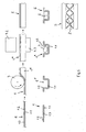
- Fig. 1 shows schematically the basic structure of a semifinished product 1 for the production of a three-dimensionally shaped hybrid component in a metal / plastic composite.
- the semifinished product 1 is essentially flat. It has at least one plate-shaped or strip-shaped sheet metal 1.1, for example sheet steel, and at least one thermoplastic plastic layer 1.2 applied in a cohesive manner to the sheet metal 1.1.
- the side of the metal sheet 1.1 on which the plastic layer 1.2 is applied has a surface (interface) 1.3 which improves the adhesion of the plastic layer.
- the metal sheet was subjected to an appropriate surface treatment.
- the surface treatment can in particular be a plasma treatment, plasma coating, corona treatment or the application of a layer in the coil coating process.
- the material connection of sheet metal 1.1 and plastic layer 1.2 is preferably carried out without an adhesive.
- the adhesion of the plastic layer 1.2 is so high that the plastic layer 1.2 does not become detached from the sheet metal 1.1 when the semi-finished product 1 is reshaped.
- the thermoplastic plastic layer 1.2 applied cohesively to the metal sheet 1.1 serves as a coupling layer for the cohesive, adhesive-free connection of at least one structural body 2 made of plastic, for example a rib body (cf. in particular Fig. 4 and Fig. 6 ).
- the thermoplastic plastic layer 1.2 consists for example of polyamide, polyethylene or a compound of these plastics and has a thickness in the range from 0.01 to 1.2 mm, preferably 0.05 to 1.0 mm, particularly preferably in the range from 0.3 to 0.8 mm.
- the flat semi-finished product 1 can be deep-drawn and is made available in plate form or as a coil for further processing.
- the in Fig. 2 The semi-finished product 1 'shown schematically is the sheet metal (eg sheet steel) 1.1 on both sides with a thermoplastic plastic layer 1.2, 1.4 serving as a coupling layer Fig. 1 coated.
- the metal sheet 1.1 has previously been surface-treated on both sides in order to achieve reliable adhesion of the respective plastic layer 1.2, 1.4 to the metal sheet 1.1.
- the surface-treated areas (interfaces) are labeled 1.3 and 1.5.
- at least one (1.2) of the thermoplastic coupling layers can only partially cover the metal sheet 1.1.
- the semi-finished product 1, 1 ' is provided for metallic forming processes.
- the at least one thermoplastic coupling layer 1.2 or 1.4 can exert a sliding effect, so that conventional lubricants, such as deep-drawing oils, can be dispensed with.
- a shaped semi-finished product (workpiece) 1, 1 ' cannot be provided in a subsequent process step with a structural body, for example a rib body, made of plastic, the structural body (rib body) 2 being integrally formed on the coupling layer 1.2 and / or 1.4 without adhesive becomes.
- a structural body for example a rib body, made of plastic
- the structural body (rib body) 2 being integrally formed on the coupling layer 1.2 and / or 1.4 without adhesive becomes.
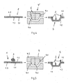
- Fig. 3 not according to the invention
- the molding tool 4 is provided with a profile that has a corresponding cavity 4.1 for pressing and three-dimensional molding of the plastic compound 3. After opening the mold 4, the finished hybrid component 5 can be removed.
- a ready-made semi-finished product 1 is formed in one process step and, in the closed state of the forming tool 4 ', is back-injected with plastic by means of an integrated injection molding device 6.
- the semifinished product 1 is heated to a certain temperature level in order to enable an optimal connection between the coupling layer of the semifinished product 1 and the plastic structure 2 to be produced by injection molding.
- the molten plastic mass is injected under pressure by means of the injection molding device 6 onto the coupling layer 1.2 of the formed semi-finished product 1, with shaping elements or cavities 4.1 formed in the forming tool causing the desired final contour of the injection-molded plastic structure.
- the finished hybrid component 5 can be removed.
- the three-dimensional structural body 2, for example rib body, of the hybrid component 5 is again produced by compression molding a plastic compound 3.
- the plastic compound 3 is placed on the flat, not yet formed semifinished product 1.
- the molding of the plastic compound 3 takes place during the shaping of the semifinished product 1 within the shaping tool 4.
- the punch 4.2 of the tool 4 has a profile with at least one integrated cavity 4.1 for pressing and three-dimensional shaping of the plastic compound 3. After opening the molding tool 4, the finished product Hybrid component 5 removed.
- FIG. 6 another exemplary embodiment of a production according to the invention of a hybrid component 5 in a metal / plastic composite is outlined.
- the hybrid component 5 is produced in this case using roll forming.
- a strip-shaped or elongated semifinished product 1 is formed into a profile 1 *, for example a U-profile or hat profile, by means of a roll-forming device 7.
- a plastic compound is then applied to its coupling layer 1.2, which is then shaped into a three-dimensional structural body or rib body 2 by means of a press having a punch 4.2 and a die 4.3.
Landscapes
- Engineering & Computer Science (AREA)
- Manufacturing & Machinery (AREA)
- Mechanical Engineering (AREA)
- Laminated Bodies (AREA)
- Injection Moulding Of Plastics Or The Like (AREA)
- Casting Or Compression Moulding Of Plastics Or The Like (AREA)
Description
- Die Erfindung betrifft ein Verfahren zur Herstellung eines dreidimensional geformten Hybridbauteils im Metall/Kunststoffverbund.
- Im Bauwesen und insbesondere im Fahrzeugbau werden in hohem Maße Leichtbauteile verwendet, welche neben einem geringen Gewicht zusätzlich hohe Festigkeiten und Steifigkeiten aufweisen müssen. Häufig dienen entsprechende Leichtbauteile in einer Fahrzeugkarosserie als crashrelevante Strukturbauteile, wie etwa eine B-Säule, ein Stoßfänger oder ein Seitenaufprallträger. Ein Ansatz zur Erreichung derartiger Leichtbauteile ist, unterschiedliche Werkstoffe miteinander zu kombinieren.
- Im Bereich Kunststoff und faserverstärkter Kunststoff hat die Firma LANXESS AG in Kooperation mit dem Lehrstuhl für Kunststofftechnik aus Erlangen den sogenannten "Erlanger Träger" entwickelt. Dies ist ein für Standarduntersuchungen verwendeter Modellträger, zu dessen Herstellung ein Organoblech (faserverstärkter Kunststoff) oberhalb seiner Schmelztemperatur erhitzt, in ein Umformwerkzeug eingelegt, umgeformt und anschließend durch ein integriertes Spritzgussaggregat mit einer dreidimensionalen Rippenstruktur versehen wird. Bei diesem Modelträger liegen die mechanischen Kennwerte signifikant höher als bei einem Pendant auf der Basis von Blech. Dadurch können solche Strukturen deutlich mehr Energie aufnehmen. Weitere Simulationen von 3-Punkt-Biegungen am Erlanger Träger haben ergeben, dass ein Verbund aus einem umgeformten Stahlblech mit einer Rippenstruktur entsprechend dem Erlanger Träger im Vergleich zur Ausgangsvariante des Erlangerträgers (Organoblech mit angespritzter Rippenstruktur) mehr als doppelt so hohe Kräfte aufnehmen kann. Da jedoch die Materialien Metall und Kunststoff artfremd sind, müssen geeignete Verbindungsmaßnahmen vorgesehen werden. Der herkömmliche Herstellungsprozess umfasst folgende Arbeitsschritte:
- 1. Stahlblech konfektionieren (zuschneiden)
- 2. zugeschnittenes Blech umformen
- 3. umgeformtes Blech entölen
- 4. Aufbringen einer Klebstoffschicht
- 5. Transportieren des umgeformten, klebstoffbeschichteten Blechs zum Spritzgusswerkzeug und Einlegen in das Werkzeug
- 6. Hinter- oder Umspritzen des Blechs mit Kunststoff, so dass eine Rippenstruktur erzeugt wird.
- Dieser Prozess ist sehr kostenintensiv. Insbesondere sind heutige Klebstoffe für die Automobilindustrie sehr preisintensiv. All dies hält viele Automobilhersteller bzw. Zulieferer von der Verwendung von Hybridbauteilen im Metall/Kunststoffverbund ab, so dass sie das insoweit vorhandene Leichtbaupotential nicht nutzen können.
- Aus der
DE 199 34 545 C1 sind Hybridbauteile bekannt, die einen aus einer Metallplatine geformten Profilkörper aufweisen, der mit Kunststoff so hinterspritzt ist, dass der Kunststoff einen kreuzförmige Rippen aufweisenden Strukturkörper definiert. Um eine ausreichende Verbindung von Metall und Kunststoff zu erreichen, wird gemäß derDE 199 34 545 C1 ein partieller Formschluss des Kunststoffs mit dem metallischen Profilkörper hergestellt. Der Formschluss wird dabei durch ein partielles Umgreifen des Profilkörpers sowie durch Umspritzen von Durchbrechungen des Profilkörpers erreicht. An den Durchbrechungen entstehen punktuelle Verankerungen zwischen Metall und Kunststoff. Diese partiellen Formschlussverbindungsstellen sind jedoch bei vielen Bauteilen hinsichtlich der äußeren Erscheinung des Bauteils unerwünscht. Zudem ist das Lastaufnahmevermögen solcher Hybridbauteile aufgrund der partiellen Formschlussverbindungen mitunter unbefriedigend. - Als weiteren Stand der Technik ist das Dokument
DE 10 2010 039 270 A1 zu nennen. - Davon ausgehend lag der Erfindung die Aufgabe zugrunde, ein Verfahren zur Herstellung eines dreidimensional geformten Hybridbauteils im Metall/Kunststoffverbund zur Verfügung zu stellen, das es Automobilherstellern bzw. ihren Zulieferern ermöglicht, entsprechende Hybridbauteile mit hohem Lastaufnahmevermögen deutlich kostengünstiger herzustellen als dies mit dem oben erwähnten, 6 Arbeitsschritte umfassenden Prozess der Fall ist.
- Die genannte Aufgabe wird durch ein Verfahren mit den Merkmalen des Anspruchs 1 gelöst. Vorteilhafte Ausgestaltungen des erfindungsgemäßen Verfahrens sind Gegenstand der auf Anspruch 1 rückbezogenen Ansprüche 2 bis 12.
- Die Erfindung basiert auf der Grundidee, für die Herstellung eines dreidimensional geformten Hybridbauteils im Metall/Kunststoffverbund ein Halbzeug zur Verfügung zustellen, das einen im Wesentlichen vollflächig haftenden Verbund zwischen Metall und Kunststoff ermöglicht, ohne dass es hierzu seitens des Automobilherstellers bzw. Hybridbauteil-Herstellers des Auftragens einer Klebstoffschicht bedarf, indem das Halbzeug aus mindestens einem platinen- oder bandförmiges Metallblech und mindestens einer darauf stoffschlüssig aufgebrachten thermoplastischen Kunststoffschicht aufgebaut ist, wobei die Seite des Metallblechs, auf welcher die Kunststoffschicht aufgebracht ist, eine die Haftung der Kunststoffschicht verbessernde Oberfläche aufweist, und wobei die Kunststoffschicht als Koppelschicht zur stoffschlüssigen, klebstofflosen Anbindung mindestens eines aus Kunststoff hergestellten oder herzustellenden Strukturkörpers ausgebildet ist.
- Je nach Oberflächenbehandlung können verschiedene thermoplastische Kunststoffe als Koppelschicht verwendet werden, insbesondere Polypropylen (PP), Polyamid (PA), Polyethylen (PE), Polyethylenterephthalat (PET), thermoplastisches Elastomer sowie Compounds dieser Kunststoffe, wobei Polyamid, Polyethylen oder deren Mischungen wegen ihrer relativ hohen Temperaturbeständigkeit besonders bevorzugt sind.
- Das Metallblech des Halbzeuges ist vorzugsweise aus Stahlwerkstoff, besonders bevorzugt aus Dualphasen-Stahl oder einem anderen Leichtbaustahl hergestellt. Stahlwerkstoff zeichnet sich durch eine gute Umformbarkeit und hohe Festigkeit aus. Das Gefüge von Dualphasen-Stahl besteht vornehmlich aus einer weichen ferritischen Matrix, in die eine zweite, harte, überwiegend martensitische Phase inselförmig eingelagert ist. Der Ferritanteil beträgt bis zu 90 %. Neben Martensit können auch Anteile von Restaustenit und Bainit vorhanden sein. Bleche aus Dualphasen-Stahl eignen sich besonders für Kaltumformungen mit hohem Streckziehanteil zur Herstellung festigkeitsrelevanter Strukturelemente und Karosserieteile. Warmgewalzter Dualphasen-Stahl weist insbesondere Vorteile bei der gewichtssparenden Herstellung von Bauteilen wie Profilen, Karosserieverstärkungen und Fahrwerksteilen auf. Nach einer entsprechenden Wärmebehandlung, z.B. der sogenannten Bake-Hardening-Behandlung, werden zusätzliche Festigkeitszuwächse von über 30 MPa erreicht.
- Das mindestens eine Metallblech des Halbzeugs hat beispielsweise eine Dicke im Bereich von 0,1 bis 2,5 mm, vorzugsweise 0,1 bis 1,0 mm, besonders bevorzugt im Bereich von 0,1 bis 0,5 mm.
- Die mindestens eine Kunststoffschicht (Koppelschicht) des Halbzeugs kann dagegen eher etwas dünner ausgebildet sein. Sie besitzt beispielsweise eine Dicke im Bereich von 0,01 bis 1,2 mm, vorzugsweise 0,05 bis 1,0 mm, besonders bevorzugt im Bereich von 0,3 bis 0,8 mm.
- In seitens der Anmelderin durchgeführten Versuchen hat sich gezeigt, dass ein Halbzeug, dessen Metallblech und Koppelschicht Dicken in den genannten Bereichen aufweisen, im Tiefungsversuch nach Erichsen bei Raumtemperatur und Werkzeugtemperatur von 100°C gut tiefziehfähig ist. Die als Koppelschicht dienende thermoplastische Kunststoffschicht fließt beim Tiefziehen des Halbzeugs mit dem Metallblech mit und verliert dabei seine Haftung nicht.
- Anstelle eines Metallblechs aus Stahlwerkstoff kann das Halbzeug auch ein Metallblech aus Magnesium oder Aluminium aufweisen.
- Die Funktion der thermoplastischen Kunststoffschicht (Koppelschicht) des Halbzeugs besteht darin, dass sich diese mit einer Vielzahl von anderen Kunststoffen zuverlässig, ohne Aufbringen von Klebstoff, stoffschlüssig verbinden lässt. Im Spritzgussprozess wird hierzu die Energie der Kunststoffschmelze genutzt, um die Oberfläche der Koppelschicht zu aktivieren und den Stoffschluss herzustellen. Nach Abkühlung der Schmelze liegt ein perfekter Verbund zwischen der Koppelschicht und dem angespritzten Kunststoff vor. Bei dem angespritzten Kunststoff kann es sich nicht nur um thermoplastischen Kunststoff, sondern auch um duroplastischen Kunststoff und/oder um einen Kunststoff aus dem Bereich der Elastomere handeln. Weiterhin ist es möglich, durch Plasma- oder Koronavorbehandlung vor dem Spritzgießprozess die Koppelschichtoberfläche zusätzlich zu aktivieren, um das Spektrum der einsetzbaren Kunststoffe zu erweitern.
- Mit dem Halbzeug lassen sich die am Standort eines Automobilherstellers bzw. Bauteilzulieferers auszuführenden Arbeitsschritte zur Herstellung eines dreidimensional geformten Hybridbauteils erheblich reduzieren. Denn der Automobilhersteller bzw. Bauteilzulieferer hat mit dem Halbzeug insbesondere die Möglichkeit, ein dreidimensional geformtes Hybridbauteils durch folgende Prozessschritte herzustellen:
- 1. Platinen- oder bandförmiges Halbzeug konfektionieren (zuschneiden)
- 2. Zugeschnittenes Halbzeug zu einem Umformwerkzeug mit integriertem Spritzgießaggregat transportieren und einlegen
- 3. Umformen und Hinterspritzen des Halbzeugzuschnitts in einem Schritt.
- Eine vorteilhafte Ausgestaltung des Halbzeugs ist dadurch gekennzeichnet, dass die Kunststoffschicht (Koppelschicht) die Seite des Metallblechs, auf welcher sie aufgebracht ist, nicht vollflächig, sondern partiell bedeckt. Diese Ausgestaltung ist insbesondere dann zweckmäßig, wenn das herzustellende Hybridbauteil beispielsweise nur partiell eine festigkeits- und/oder steifigkeitserhöhende Rippenstruktur aus Kunststoff aufweist. Ein oder mehrere größere Flächenbereiche des Metallblechs, die nach Fertigstellung des Hybridbauteils keine Rippenstruktur aufweisen sollen, können somit beim Beschichten des Metallblechs mit der mindestens einen thermoplastischen Kunststoffschicht (Koppelschicht) unbeschichtet bleiben. Dies spart Materialkosten und trägt zu einer optimierten Gewichtseinsparung bei ausreichenden Festigkeits- bzw. Steifigkeitseigenschaften bei.
- Eine weitere vorteilhafte Ausgestaltung des Halbzeugs besteht darin, dass die thermoplastische Kunststoffschicht doppelt ausgeführt ist, wobei zwischen den beiden Kunststoffschichten eine thermoplastische Schaumstoffschicht angeordnet ist. Es hat sich gezeigt, dass die Zwischenanordnung einer thermoplastischen Schaumstoffschicht deutlich zur Gewichtsreduzierung des Hybridbauteils bei gleichbleibender Festigkeit und Steifigkeit beitragen kann.
- Nach einer weiteren vorteilhaften Ausgestaltung ist die Kunststoffschicht (Koppelschicht) des Halbzeugs partiell mit mindestens einem Organoblech beschichtet. Hierdurch kann die Festigkeit und Steifigkeit des herzustellenden Hybridbauteils bei gleichbleibendem oder sogar vermindertem Gesamtgewicht deutlich verbessert werden.
- Alternativ oder zusätzlich kann nach einer weiteren Ausgestaltung des Halbzeugs auch dessen (mindestens eines) Metallblech auf seiner der Kunststoffschicht (Koppelschicht) abgewandten Seite mit mindestens einem Organoblech beschichtet sein. Auch durch diese Ausgestaltung kann die Festigkeit und Steifigkeit des herzustellenden Hybridbauteils bei gleichbleibendem oder sogar vermindertem Gesamtgewicht deutlich erhöht werden. Dabei kann nach einer weiteren Ausgestaltung das Organoblech auf seiner dem Metallblech abgewandten Seite mit mindestens einem zweiten Metallblech beschichtet sein. Aus einem solchen Halbzeug lassen sich besonders leichte und zugleich sehr feste und steife Hybridbauteile herstellen, insbesondere dann, wenn das Organoblech nach einer bevorzugten Ausgestaltung Kohlenstofffasern enthält. Zudem kann in weiterer Ausgestaltung das zweite Metallblech außenseitig mit einer thermoplastischen Kunststoffschicht beschichtet sein, die ebenfalls als Koppelschicht zur stoffschlüssigen, klebstofflosen Anbindung mindestens eines aus Kunststoff hergestellten oder herzustellenden Strukturkörpers ausgebildet ist. Aus einem derart ausgestalteten Halbzeug lassen sich vorteilhaft, ohne einen Auftrag von Klebstoff, Hybridbauteile herstellen, die beidseitig aus Kunststoff hergestellte Strukturkörper, insbesondere Rippenkörper aufweisen.
- Eine andere vorteilhafte Ausgestaltung des Halbzeugs besteht darin, dass das Metallblech auf seiner der Kunststoffschicht abgewandten Seite mit einer zweiten thermoplastischen Kunststoffschicht beschichtet ist, die ebenfalls als Koppelschicht zur stoffschlüssigen, klebstofflosen Anbindung mindestens eines aus Kunststoff hergestellten oder herzustellenden Strukturkörpers ausgebildet ist. Auch aus einem solchen Halbzeug lassen sich ohne Auftrag von Klebstoff Hybridbauteile herstellen, die beidseitig aus Kunststoff hergestellte Strukturkörper, insbesondere Rippenkörper aufweisen.
- Dabei kann die zweite Kunststoffschicht (Koppelschicht) die Seite des Metallblechs, auf welcher sie aufgebracht ist, vollflächig oder partiell bedecken. Die partielle Beschichtung des Metallblechs durch die zweite Kunststoffschicht ist zum Beispiel zweckmäßig, wenn das herzustellende Hybridbauteil auf der entsprechenden Seite des Metallblechs nur partiell eine Rippenstruktur aus Kunststoff aufweist, die ohne Klebstoff über die partielle Koppelschicht an das Metallblech stoffschlüssig angebunden ist.
- Eine weitere vorteilhafte Ausgestaltung des Halbzeugs besteht darin, dass die zweite Kunststoffschicht auf ihrer dem Metallblech abgewandten Seite mit einem zweiten Metallblech beschichtet ist. Das zweite Metallblech kann dabei in weiterer Ausgestaltung auf seiner der zweiten Kunststoffschicht abgewandten Seite mit einer dritten thermoplastischen Kunststoffschicht als Koppelschicht beschichtet sein. Auch mit derart ausgestalteten Halbzeugen lassen sich leichtgewichtige Hybridbauteile mit hoher Festigkeit und Steifigkeit kostengünstig herstellen. Das Gleiche gilt für eine weitere Ausgestaltung des Halbzeugs, bei welcher die zweite Kunststoffschicht vollflächig oder partiell mit mindestens einem Organoblech beschichtet ist.
- Nach einer weiteren Ausgestaltung des Halbzeugs ist die jeweilige als Koppelschicht dienende Kunststoffschicht mit einer abziehbaren Schutzfolie versehen. Die Schutzfolie schützt die Oberfläche der Koppelschicht während des Transportes des Halbzeuges sowie gegebenenfalls auch während des Umformens des Halbzeugs. Hierdurch kann vor dem Anformen von Kunststoffstrukturen, beispielsweise Kunststoffrippen, ein aufwendiges Reinigen der Koppelschichtoberfläche von Verschmutzungen wie Öl oder Fett entfallen. Zudem kann die Schutzfolie als Ziehfolie die Gleiteigenschaften des Halbzeuges beim Umformen verbessern.
- Das Halbzeug ist vorzugsweise als Flachprodukt ausgebildet. Es kann mittels einer Plattenpresse in einem statischen Prozess, einer Intervallheizpresse in einem diskontinuierlichen Prozess oder einer Laminieranlage, beispielsweise einer Doppelbandpresse, in einem kontinuierlichen Prozess hergestellt werden. Die Prozessparameter werden dabei jeweils speziell auf das herzustellende Halbzeug eingestellt. Je nach Halbzeugvarianten können daraus Tafeln geschnitten werden; oder das bandförmige Halbzeug kann zu einem Coil aufgerollt werden.
- Gemäß der vorliegenden Erfindung wird die oben aufgezeigte Aufgabe für ein Verfahren zur Herstellung eines dreidimensional geformten Hybridbauteils im Metall/Kunststoffverbund durch die Verwendung eines Halbzeugs in einer der oben genannten Ausgestaltungen gelöst, wobei an die als Koppelschicht ausgebildete Kunststoffschicht durch Spritzgießen oder Pressformen ein Strukturkörper aus Kunststoff stoffschlüssig angeformt wird.
- Wie bereits ausgeführt, ermöglicht das Halbzeug die Herstellung eines dreidimensional geformten Hybridbauteils aus Metall und Kunststoff mit einem Strukturkörper, vorzugsweise Rippenkörper, aus Kunststoff ohne Auftrag von Klebstoff. Dies vereinfacht die Herstellung des Hybridbauteils deutlich.
- Eine zweckmäßige Ausgestaltung des erfindungsgemäßen Verfahrens besteht darin, dass das Halbzeug vor dem Anformen des Strukturkörpers in eine dreidimensionale Form umgeformt wird. Das Umformen wird dabei vorzugsweise durch Tiefziehen oder Rollformen ausgeführt.
- Eine erste Alternative des erfindungsgemäßen Verfahrens ist dadurch gekennzeichnet, dass das Halbzeug mittels eines Umformwerkzeuges, das mindestens eine integrierte Spritzgießkavität und mindestens einen in die Spritzgießkavität mündenden Spritzgießkanal aufweist, umgeformt wird, wobei an dem Hybridbauteil mindestens ein integraler Flansch ausgebildet wird, der die als Koppelschicht ausgebildete thermoplastische Kunststoffschicht aufweist, und dass an die Kunststoffschicht ein weiteres als Metall/Kunststoffverbund ausgeführtes Hybridbauteil oder ein Organoblech durch Schweißen angefügt wird. Diese Ausgestaltung bietet die Möglichkeit, die Anzahl der Prozessschritte zur Herstellung des Hybridbauteils zu reduzieren, indem das Umformen des Halbzeuges bzw. Halbzeugzuschnitts und das Hinterspritzen der Koppelschicht zur Erzeugung des Strukturkörpers, vorzugsweise Rippenkörpers, im gleichen Prozessschritt durchgeführt werden.
- Eine zweite Alternative des erfindungsgemäßen Verfahrens ist dadurch gekennzeichnet, dass das Halbzeug mittels eines Umformwerkzeuges, welches ein Profil mit mindestens einer integrierten Kavität zum Verpressen und dreidimensionalen Formen einer Kunststoffmasse aufweist, umgeformt wird, wobei an dem Hybridbauteil mindestens ein integraler Flansch ausgebildet wird, der die als Koppelschicht ausgebildete thermoplastische Kunststoffschicht aufweist, und dass an die Kunststoffschicht ein weiteres als Metall/Kunststoffverbund ausgeführtes Hybridbauteil oder ein Organoblech durch Schweißen angefügt wird. Auch diese Variante bietet die Möglichkeit, die Anzahl der Prozessschritte zur Herstellung des Hybridbauteils zu reduzieren, indem das Umformen des Halbzeuges bzw. Halbzeugzuschnitts und das Verpressen der Kunststoffmasse zur Erzeugung des Strukturkörpers, vorzugsweise Rippenkörpers, auf der Koppelschicht im gleichen Prozessschritt durchgeführt werden.
- Eine weitere Variante des erfindungsgemäßen Verfahrens besteht darin, dass das Halbzeug durch Rollformen umgeformt wird, wobei während oder nach dem Umformen des Halbzeuges ein rotierbares, radförmiges Werkzeug zum Pressformen des Strukturkörpers verwendet wird, und wobei das Werkzeug mit einem mindestens eine Kavität aufweisenden Profil zum Verpressen und dreidimensionalen Formen einer Kunststoffmasse versehen ist. Mit dieser Ausgestaltung des Verfahrens lassen sich insbesondere als Profilträger ausgebildete Hybridbauteile der genannten Art in Großserie effektiv herstellen.
- Erfindungsgemäß wird an dem Hybridbauteil mindestens ein integraler Flansch ausgebildet, der die als Koppelschicht ausgebildete thermoplastische Kunststoffschicht aufweist, wobei an die Kunststoffschicht ein weiteres als Metall/Kunststoffverbund ausgeführtes Hybridbauteil oder ein Organoblech durch Schweißen angefügt wird. Auf diese Weise lassen sich beispielsweise als Halbschalen ausgebildete Hybridbauteile kostengünstig zu einem Hohlkanal oder geschlossenen Profil zusammensetzen. Entsprechendes gilt hinsichtlich einer Kombination eines Hybridbauteils mit einem den Hohlkanal bzw. das geschlossene Profil begrenzenden Organoblech. Die Schweißverbindung der als Halbschalen ausgebildeten Hybridbauteile bzw. des Organoblechs mit einem einzelnen Hybridbauteil kann beispielsweise durch Reibschweißen, Punktschweißen, Ultraschallschweißen etc. erzeugt werden.
- Das Halbzeug wird vorteilhaft zur Herstellung eines dreidimensional geformten Hybridbauteils als Bauteil für ein Fahrzeug, Flugzeug, Schiff oder Bauwerk verwendet. Vorteile ergeben sich nämlich durch das Halbzeug überall dort, wo eine Gewichtseinsparung gefragt ist und hierzu Hybridbauteile der genannten Art in möglichst wenigen Prozessschritten hergestellt werden sollen.
- Nachfolgend wird die Erfindung anhand einer mehrere Ausführungsbeispiele darstellenden Zeichnung näher erläutert.
-
Fig. 1 zeigt schematisch den Grundaufbau eines Halbzeugs 1 zur Herstellung eines dreidimensional geformten Hybridbauteils im Metall/Kunststoffverbund. Das Halbzeug 1 ist im Wesentlichen flächig ausgebildet. Es weist mindestens ein platinen- oder bandförmiges Metallblech 1.1, beispielsweise Stahlblech, und mindestens eine auf dem Metallblech 1.1 stoffschlüssig aufgebrachte thermoplastische Kunststoffschicht 1.2 auf. Die Seite des Metallblechs 1.1, auf der die Kunststoffschicht 1.2 aufgebracht ist, besitzt eine die Haftung der Kunststoffschicht verbessernde Oberfläche (Grenzfläche) 1.3. Hierzu wurde das Metallblech einer entsprechenden Oberflächenbehandlung unterworfen. Bei der Oberflächenbehandlung kann es sich insbesondere um eine Plasmabehandlung, Plasmabeschichtung, Koronabehandlung oder das Auftragen einer Schicht im Coil-Coating-Verfahren handeln. Die stoffschlüssige Verbindung von Metallblech 1.1 und Kunststoffschicht 1.2 erfolgt vorzugsweise ohne Klebstoff. Die Haftung der Kunststoffschicht 1.2 ist so hoch, dass es beim Umformen des Halbzeuges 1 zu keinem Ablösen der Kunststoffschicht 1.2 vom Metallblech 1.1 kommt. - Die stoffschlüssig auf das Metallblech 1.1 aufgebrachte thermoplastische Kunststoffschicht 1.2 dient als Koppelschicht zur stoffschlüssigen, klebstofflosen Anbindung mindestens eines aus Kunststoff hergestellten oder herzustellenden Strukturkörpers 2, beispielsweise Rippenkörpers (vgl. insbesondere
Fig.4 undFig. 6 ). Die thermoplastische Kunststoffschicht 1.2 besteht beispielsweise aus Polyamid, Polyethylen oder einem Compound dieser Kunststoffe und weist eine Dicke im Bereich von 0,01 bis 1,2 mm, vorzugsweise 0,05 bis 1,0 mm, besonders bevorzugt im Bereich von 0,3 bis 0,8 mm auf. Das flächige Halbzeug 1 ist tiefziehfähig und wird in Plattenform oder als Coil zur Weiterverarbeitung bereitgestellt. - Bei dem in
Fig. 2 schematisch dargestellten Halbzeug 1' ist das Metallblech (z.B. Stahlblech) 1.1 beidseitig mit einer als Koppelschicht dienenden thermoplastischen Kunststoffschicht 1.2, 1.4 entsprechendFig. 1 beschichtet. Hierzu wurde das Metallblech 1.1 zuvor beidseitig oberflächenbehandelt, um eine zuverlässige Haftung der jeweiligen Kunststoffschicht 1.2, 1.4 an dem Metallblech 1.1 zu erreichen. Die oberflächenbehandelten Flächen (Grenzflächen) sind mit 1.3 und 1.5 bezeichnet. Wie inFig. 2 gezeigt, kann mindestens eine (1.2) der thermoplastischen Koppelschichten das Metallblech 1.1 nur partiell bedecken. - Das Halbzeug 1, 1' wird für metallische Umformprozesse bereitgestellt. Hierbei kann die mindestens eine thermoplastische Koppelschicht 1.2 bzw. 1.4 eine gleitende Wirkung ausüben, so dass auf übliche Schmier- und Gleitmittel, wie etwa Tiefziehöle, verzichtet werden kann.
- Ein umgeformtes Halbzeug (Werkstück) 1, 1' kann nicht erfindungsgemäß in einem nachfolgenden Prozessschritt mit einem Strukturkörper, beispielsweise einem Rippenkörper, aus Kunststoff versehen werden, wobei der Strukturkörper (Rippenkörper) 2 an die Koppelschicht 1.2 und/oder 1.4 stoffschlüssig, ohne Klebstoff angeformt wird. Dies kann durch Spritzgießen oder, wie in
Fig. 3 (nicht erfindungsgemäß) skizziert, durch Formpressen einer plastifizierten Kunststoffmasse 3 erfolgen. Das Formwerkzeug 4 ist hierzu mit einem eine entsprechende Kavität 4.1 aufweisenden Profil zum Verpressen und dreidimensionalen Formen der Kunststoffmasse 3 versehen. Nach Öffnen des Formwerkzeuges 4 kann das fertige Hybridbauteil 5 entnommen werden. - Bei dem in
Fig. 4 schematisch dargestellten Ausführungsbeispiel wird ein konfektioniertes Halbzeug 1 in einem Prozessschritt umgeformt und im geschlossenen Zustand des Umformwerkzeuges 4' mittels eines integrierten Spritzgusseinrichtung 6 mit Kunststoff hinterspritzt. Das Halbzeug 1 wird hierzu auf ein bestimmtes Temperaturniveau erwärmt, um eine optimale Verbindung zwischen der Koppelschicht des Halbzeuges 1 und der durch Spritzgießen herzustellenden Kunststoffstruktur 2 zu ermöglichen. Die schmelzflüssige Kunststoffmasse wird unter Druck mittels der Spritzgießeinrichtung 6 auf die Koppelschicht 1.2 des umgeformten Halbzeugs 1 gespritzt, wobei in dem Umformwerkzeug ausgebildete Formgebungselemente bzw. Kavitäten 4.1 die gewünschte Endkontur der angespritzten Kunststoffstruktur bewirken. Nach Öffnen des Formwerkzeuges 4 kann das fertige Hybridbauteil 5 entnommen werden. - Bei dem in
Fig. 5 schematisch dargestellten Ausführungsbeispiel wird der dreidimensionale Strukturkörper 2, beispielsweise Rippenkörper, des Hybridbauteils 5 wiederum durch Formpressen einer Kunststoffmasse 3 hergestellt. In diesem Beispiel wird die Kunststoffmasse 3 auf das flächige, noch nicht umgeformte Halbzeug 1 abgelegt. Das Formen der Kunststoffmasse 3 erfolgt während des Umformens des Halbzeuges 1 innerhalb des Umformwerkzeuges 4. Der Stempel 4.2 des Werkzeuges 4 hat hierzu ein Profil mit mindestens einer integrierten Kavität 4.1 zum Verpressen und dreidimensionalen Formen der Kunststoffmasse 3. Nach Öffnen des Formwerkzeuges 4 wird das fertige Hybridbauteil 5 entnommen. - In
Fig. 6 ist ein weiteres Ausführungsbeispiel einer erfindungsgemäßen Herstellung eines Hybridbauteils 5 im Metall/Kunststoffverbund skizziert. Das Hybridbauteil 5 wird in diesem Fall unter Anwendung von Rollformen hergestellt. Ein bandförmiges oder längliches Halbzeug 1 wird mittels einer Rollformvorrichtung 7 in ein Profil 1*, beispielsweise ein U-Profil oder Hutprofil umgeformt. In das umgeformte Halbzeug 1 (Profil 1*) wird dann auf dessen Koppelschicht 1.2 eine Kunststoffmasse aufgebracht, die anschließend mittels einer einen Stempel 4.2 und eine Matrize 4.3 aufweisenden Presse zu einem dreidimensionalen Strukturkörper bzw. Rippenkörper 2 geformt wird. - Die Ausführung der Erfindung ist nicht auf die in der Zeichnung schematisch dargestellten Ausführungsbeispiele beschränkt. Vielmehr sind zahlreiche Varianten möglich, die auch bei von der Zeichnung abweichender Gestaltung von der in den Ansprüchen angegebenen Erfindung Gebrauch machen. So kann das Halbzeug 1, 1' insbesondere noch mindestens eine weitere Metallblechschicht, Kunststoffschicht (Koppelschicht) und/oder Organoblechschicht aufweisen. Ferner liegt es im Rahmen der Erfindung, das Halbzeug 1, 1' durch Rollformen umzuformen, wobei während dem Umformen des Halbzeuges ein rotierbares, radförmiges Werkzeug zum Pressformen des Strukturkörpers 2 verwendet wird, und wobei das Werkzeug mit einem mindestens eine Kavität aufweisenden Profil zum Verpressen und dreidimensionalen Formen einer Kunststoffmasse 3 versehen ist.
Claims (12)
- Verfahren zur Herstellung eines dreidimensional geformten Hybridbauteils (5) im Metall/Kunststoffverbund, gekennzeichnet durch die Verwendung eines tiefziehfähigen, platinen- oder bandförmigen Halbzeugs (1, 1'), das mindestens ein platinen- oder bandförmiges Metallblech (1.1) und mindestens eine auf dem Metallblech stoffschlüssig aufgebrachte thermoplastische Kunststoffschicht (1.2, 1.4) aufweist, wobei die Seite des Metallblechs (1.1), auf welcher die Kunststoffschicht (1.2, 1.4) aufgebracht ist, eine die Haftung der Kunststoffschicht (1.2, 1.4) verbessernde Oberfläche (1.3, 1.5) aufweist, wobei die Kunststoffschicht (1.2, 1.4) als Koppelschicht zur stoffschlüssigen, klebstofflosen Anbindung mindestens eines aus Kunststoff hergestellten oder herzustellenden Strukturkörpers (2) ausgebildet ist, wobei an die als Koppelschicht ausgebildete Kunststoffschicht (1.2, 1.4) durch Spritzgießen oder Pressformen ein Strukturkörper (2) aus Kunststoff stoffschlüssig angeformt wird, wobei das Halbzeug (1, 1') mittels eines Umformwerkzeuges (4'), das mindestens eine integrierte Spritzgießkavität (4.1) und mindestens einen in die Spritzgießkavität (4.1) mündenden Spritzgießkanal aufweist, oder mittels eines Umformwerkzeuges (4), das ein Profil mit mindestens einer integrierten Kavität (4.1) zum Verpressen und dreidimensionalen Formen einer Kunststoffmasse (3) aufweist, umgeformt wird,
wobei an dem Hybridbauteil (5) mindestens ein integraler Flansch ausgebildet wird, der die als Koppelschicht ausgebildete thermoplastische Kunststoffschicht (1.2) aufweist, und dass an die Kunststoffschicht (1.2) ein weiteres als Metall/Kunststoffverbund ausgeführtes Hybridbauteil (5) oder ein Organoblech durch Schweißen angefügt wird. - Verfahren nach Anspruch 1, dadurch gekennzeichnet, dass das Halbzeug vor dem Anformen des Strukturkörpers (2) in eine dreidimensionale Form umgeformt wird.
- Verfahren nach Anspruch 2, dadurch gekennzeichnet, dass das Umformen durch Tiefziehen oder Rollformen ausgeführt wird.
- Verfahren nach Anspruch 1, dadurch gekennzeichnet, dass das Halbzeug (1, 1') durch Rollformen umgeformt wird, wobei während oder nach dem Umformen des Halbzeuges ein rotierbares, radförmiges Werkzeug zum Pressformen des Strukturkörpers (2) verwendet wird, und wobei das Werkzeug mit einem mindestens eine Kavität aufweisenden Profil zum Verpressen und dreidimensionalen Formen einer Kunststoffmasse (3) versehen ist.
- Verfahren nach Anspruch 4, dadurch gekennzeichnet, dass die beiden Hybridbauteile (5) zu einem Hohlkanal oder geschlossenen Profil zusammengesetzt werden.
- Verfahren nach Anspruch 4, dadurch gekennzeichnet, dass das Hybridbauteil und das Organoblech zu einem Hohlkanal oder geschlossenen Profil zusammengesetzt werden.
- Verfahren nach einem der Ansprüche 1 bis 6, dadurch gekennzeichnet, dass das Metallblech (1.1) des verwendeten Halbzeugs (1, 1') eine Dicke im Bereich von 0,1 bis 2,5 mm, vorzugsweise 0,1 bis 1,0 mm, besonders bevorzugt im Bereich von 0,1 bis 0,5 mm aufweist.
- Verfahren nach einem der Ansprüche 1 bis 7, dadurch gekennzeichnet, dass die Kunststoffschicht (1.2, 1.4) des verwendeten Halbzeugs (1, 1') aus Polyamid, Polyethylen, Polypropylen, thermoplastischem Elastomer oder deren Mischungen hergestellt ist.
- Verfahren nach einem der Ansprüche 1 bis 8, dadurch gekennzeichnet, dass die Kunststoffschicht (1.2, 1.4) des verwendeten Halbzeugs (1, 1') eine Dicke im Bereich von 0,01 bis 1,2 mm, vorzugsweise 0,05 bis 1,0 mm, besonders bevorzugt im Bereich von 0,3 bis 0,8 mm aufweist.
- Verfahren nach einem der Ansprüche 1 bis 9, dadurch gekennzeichnet, dass die Kunststoffschicht (1.2) des verwendeten Halbzeugs (1') die Seite des Metallblechs (1.1), auf welcher sie aufgebracht ist, partiell bedeckt.
- Verfahren nach einem der Ansprüche 1 bis 10, dass die thermoplastische Kunststoffschicht (1.2, 1.4) des verwendeten Halbzeugs (1, 1') doppelt ausgeführt ist, wobei zwischen den beiden Kunststoffschichten eine thermoplastische Schaumstoffschicht angeordnet ist.
- Verfahren nach einem der Ansprüche 1 bis 11, dadurch gekennzeichnet, dass die Kunststoffschicht (1.2, 1.4) des verwendeten Halbzeugs (1,1') partiell mit mindestens einem Organoblech beschichtet ist.
Priority Applications (1)
| Application Number | Priority Date | Filing Date | Title |
|---|---|---|---|
| PL14755351T PL3041674T5 (pl) | 2013-09-03 | 2014-08-20 | Półfabrykat i sposób wytwarzania trójwymiarowo formowanego hybrydowego elementu konstrukcyjnego w kompozycie metal/tworzywo sztuczne jak i zastosowanie takiego półfabrykatu |
Applications Claiming Priority (2)
| Application Number | Priority Date | Filing Date | Title |
|---|---|---|---|
| DE201310109616 DE102013109616A1 (de) | 2013-09-03 | 2013-09-03 | Halbzeug und Verfahren zur Herstellung eines dreidimensional geformten Hybridbauteils im Metall/Kunststoffverbund sowie Verwendung eines solchen Halbzeuges |
| PCT/EP2014/067763 WO2015032623A1 (de) | 2013-09-03 | 2014-08-20 | Halbzeug und verfahren zur herstellung eines dreidimensional geformten hybridbauteils im metall/kunststoffverbund sowie verwendung eines solchen halbzeugs |
Publications (3)
| Publication Number | Publication Date |
|---|---|
| EP3041674A1 EP3041674A1 (de) | 2016-07-13 |
| EP3041674B1 EP3041674B1 (de) | 2017-08-02 |
| EP3041674B2 true EP3041674B2 (de) | 2020-10-21 |
Family
ID=51398609
Family Applications (1)
| Application Number | Title | Priority Date | Filing Date |
|---|---|---|---|
| EP14755351.5A Not-in-force EP3041674B2 (de) | 2013-09-03 | 2014-08-20 | Halbzeug und verfahren zur herstellung eines dreidimensional geformten hybridbauteils im metall/kunststoffverbund sowie verwendung eines solchen halbzeugs |
Country Status (11)
| Country | Link |
|---|---|
| US (1) | US20160207234A1 (de) |
| EP (1) | EP3041674B2 (de) |
| JP (1) | JP6438481B2 (de) |
| KR (1) | KR20160051835A (de) |
| CN (1) | CN105517794B (de) |
| CA (1) | CA2922226C (de) |
| DE (1) | DE102013109616A1 (de) |
| ES (1) | ES2645426T5 (de) |
| MX (1) | MX2016002469A (de) |
| PL (1) | PL3041674T5 (de) |
| WO (1) | WO2015032623A1 (de) |
Families Citing this family (40)
| Publication number | Priority date | Publication date | Assignee | Title |
|---|---|---|---|---|
| DE102013106070C5 (de) * | 2013-06-12 | 2019-10-24 | Leichtbau-Zentrum Sachsen Gmbh | Seitenwandgruppe für Personenkraftwagen |
| DE102013109616A1 (de) | 2013-09-03 | 2015-03-05 | Thyssenkrupp Steel Europe Ag | Halbzeug und Verfahren zur Herstellung eines dreidimensional geformten Hybridbauteils im Metall/Kunststoffverbund sowie Verwendung eines solchen Halbzeuges |
| FR3029062B1 (fr) * | 2014-11-21 | 2019-06-21 | Airbus Group Sas | Dispositif conducteur destine a etre monte en surface des pieces en materiaux composites et procede pour realiser un tel dispositif |
| DE102014017492A1 (de) | 2014-11-27 | 2016-06-02 | Thyssenkrupp Ag | Halbzeug, Verfahren zum Herstellen eines Halbzeugs sowie dessen Verwendung |
| FR3030356B1 (fr) * | 2014-12-23 | 2019-04-05 | Renault S.A.S | Procede de fabrication d'une piece de structure hybride de vehicule automobile et piece de structure hybride correspondante. |
| DE102015111336A1 (de) * | 2015-07-13 | 2017-01-19 | CONTTEK Holding GmbH | Beschichtung von Stanzteilen mithilfe von Plasma-Beschichtungsverfahren |
| DE102015226474A1 (de) * | 2015-12-22 | 2017-06-22 | Thyssenkrupp Ag | Halbzeug für die Herstellung von Hohlprofilen, Hohlprofile hieraus sowie Verfahren zu deren Herstellung |
| HUE045857T2 (hu) * | 2016-03-23 | 2020-01-28 | Smp Deutschland Gmbh | Berendezés és eljárás legalább egy kivágással rendelkezõ sajtolt formadarab elõállítására |
| KR101815374B1 (ko) | 2016-04-25 | 2018-01-04 | 울산대학교 산학협력단 | 적층기재의 제조방법 |
| FR3056144B1 (fr) | 2016-09-16 | 2018-10-12 | Plastic Omnium Cie | Procede de fabrication ameliore d'une piece de structure hybride de vehicule automobile et piece de structure hybride correspondante |
| DE102016218596B3 (de) | 2016-09-27 | 2018-01-11 | Thyssenkrupp Ag | Halbzeug mit Funktionselementen für Bauteile, Bauteil aus diesem Halbzeug sowie Verfahren für die Bauteilherstellung |
| DE102017202373A1 (de) * | 2017-02-15 | 2018-08-16 | Thyssenkrupp Ag | Gehäuse für elektrische Maschinen in Halbschalenbauweise und Verfahren für dessen Herstellung |
| DE102017206916A1 (de) | 2017-04-25 | 2018-10-25 | Thyssenkrupp Ag | Verfahren zum Verbinden eines Metall-Polymer-Laminats |
| DE102017217763A1 (de) | 2017-10-06 | 2019-04-11 | Thyssenkrupp Ag | Verfahren zur Herstellung von Hybridbauteilen sowie Verwendungen solcher Hybridbauteile |
| DE102017125264A1 (de) | 2017-10-27 | 2019-05-02 | Kautex Textron Gmbh & Co. Kg | Flüssigkeitsbehälter für ein Kraftfahrzeug und Verfahren zum Herstellen eines Flüssigkeitsbehälters |
| DE102017220204A1 (de) * | 2017-11-14 | 2019-05-16 | Thyssenkrupp Ag | Kolbenstange mit Kolben, insbesondere für einen fluidtechnischen Aktor und Verfahren zum Herstellen einer Kolbenstange mit Kolben |
| DE102018204407A1 (de) | 2018-03-22 | 2019-09-26 | Thyssenkrupp Ag | Funktionsintegrierte Temperierung in Stahl-Kunststoff-Hybriden durch wärmeleitfähige Füllstoffe |
| DE102018207205A1 (de) * | 2018-05-09 | 2019-11-14 | Thyssenkrupp Ag | Hybrides Stahl-Kunststoffgehäuse für Leistungselektronik |
| DE102018207211A1 (de) * | 2018-05-09 | 2019-11-14 | Thyssenkrupp Ag | Hybrides Stahl-Kunststoffhalbzeug mit Abschirmeigenschaften |
| DE102018207648A1 (de) | 2018-05-16 | 2019-11-21 | Thyssenkrupp Ag | Hybrides Metall-Kunststoff-Abschirmungselement zur Einbettung von Leiterbahnen |
| JP6997974B2 (ja) * | 2018-05-24 | 2022-01-20 | 日産自動車株式会社 | 自動車部品 |
| KR102109354B1 (ko) * | 2018-11-29 | 2020-05-12 | 이성기 | 기물의 외주면 장식을 보호하는 철판 가공방법 |
| DE102019204582A1 (de) * | 2019-04-01 | 2020-10-01 | Volkswagen Aktiengesellschaft | Verfahren zum Hinterspritzen von kaltverformten Glaskomponenten mit Kunststoff |
| DE102019108984B3 (de) * | 2019-04-05 | 2020-09-24 | Salzgitter Flachstahl Gmbh | Verwendung eines bandbeschichteten Blechs mit einer organischen Beschichtung |
| CA3144447A1 (en) * | 2019-06-21 | 2020-12-24 | Magna Exteriors Inc. | Three dimensional overmolding |
| DE102019213768A1 (de) | 2019-09-10 | 2021-03-11 | Thyssenkrupp Steel Europe Ag | Toleranzausgleich durch Metall-Kunststoff-Hybridwerkstoff |
| EP4039462A4 (de) * | 2019-10-04 | 2022-11-02 | Nippon Steel Corporation | Metall-(faserverstärktes harz)-komplex, metall-(faserverstärktes harz)-komplexeinheit, verfahren zur herstellung eines metall-(faserverstärktes harz)-komplexes und automobilbauteil |
| DE102020202818A1 (de) | 2020-03-05 | 2021-09-09 | Thyssenkrupp Steel Europe Ag | Hybrides Metall-Kunststoffhalbzeug mit verbessertem Wärmedurchgang |
| DE102020202813A1 (de) | 2020-03-05 | 2021-09-09 | Thyssenkrupp Steel Europe Ag | Drückwalzen von Metall-Kunststoff-Halbzeugen |
| CN111370810B (zh) * | 2020-03-31 | 2024-09-06 | 苏州方林科技股份有限公司 | 一种基于金属塑料复合材制备的液冷散热板及其制备工艺 |
| DE102020204360A1 (de) | 2020-04-03 | 2021-10-07 | Volkswagen Aktiengesellschaft | Verfahren zur Herstellung eines Verbundbauteils, eine das Verbundbauteil umfassende Baugruppe sowie ein Kraftfahrzeug |
| DE102020110241B4 (de) | 2020-04-15 | 2023-02-02 | Thyssenkrupp Steel Europe Ag | Karosseriesäule, insbesondere A-Säule, für ein Kraftfahrzeug |
| JP7475215B2 (ja) * | 2020-06-29 | 2024-04-26 | Nok株式会社 | ガスケットの製造方法 |
| US11655872B2 (en) | 2021-05-05 | 2023-05-23 | Buffers Usa, Inc. | Joining elastic material to metal |
| JP2022189011A (ja) * | 2021-06-10 | 2022-12-22 | 株式会社神戸製鋼所 | 金属樹脂複合体を製造するための金型、装置、および方法 |
| CN115696888A (zh) * | 2021-07-22 | 2023-02-03 | 启碁科技股份有限公司 | 屏蔽结构及其制造方法 |
| JP7560059B2 (ja) * | 2021-10-08 | 2024-10-02 | 株式会社神戸製鋼所 | 金属樹脂複合体を製造するための装置、金型セット、および方法 |
| CN114952210B (zh) * | 2022-06-07 | 2023-07-21 | 无锡市豫达换热器有限公司 | 一种铝制板翅式换热器的制造工艺 |
| DE102022124171B3 (de) * | 2022-09-21 | 2023-12-28 | Dr. Ing. H.C. F. Porsche Aktiengesellschaft | Verfahren zur Ermittlung einer Druckverteilung einer Formwerkzeugeinrichtung sowie Verbundblechbauteil und Blechbauteil |
| CN117382069B (zh) * | 2023-12-12 | 2024-04-12 | 北京玻钢院复合材料有限公司 | 一种内埋金属件的低密度防热层整体模压成型方法 |
Citations (2)
| Publication number | Priority date | Publication date | Assignee | Title |
|---|---|---|---|---|
| WO2005061203A2 (de) † | 2003-12-22 | 2005-07-07 | Robert Bosch Gmbh | Bauteil mit kunststoff-metall-verbund und herstellung des bauteils |
| WO2014118213A1 (de) † | 2013-01-29 | 2014-08-07 | Evonik Industries Ag | Haftvermittler- und primer-zusammensetzungen für metall-kunststoff-hybridbauteile |
Family Cites Families (29)
| Publication number | Priority date | Publication date | Assignee | Title |
|---|---|---|---|---|
| JPS5231388B1 (de) * | 1969-07-31 | 1977-08-15 | ||
| JPS56144956A (en) * | 1980-04-14 | 1981-11-11 | Toyo Kogyo Co | Composite lid structure for automobile |
| JPS6198646A (ja) * | 1984-10-18 | 1986-05-16 | Toyoda Gosei Co Ltd | トリムストリツプ |
| US5035940A (en) * | 1988-09-19 | 1991-07-30 | Rexham Corporation | Aluminum-fluoropolymer laminate |
| DE3839855A1 (de) * | 1988-11-25 | 1990-05-31 | Bayer Ag | Leichtbauteil |
| US20050225006A1 (en) * | 1995-11-01 | 2005-10-13 | Patent Holding Company | Method for molding metal-covered component |
| TW387843B (en) * | 1998-02-05 | 2000-04-21 | Juang Dung Han | Method of producing EMI-shielding plastic product with one face of which clad with metal foil and the device thereof |
| DE19914092C2 (de) * | 1998-04-23 | 2001-10-04 | Daimler Chrysler Ag | Verfahren und Vorrichtung zur Herstellung eines Verkleidungs- und Zierteils und danach hergestelltes Verkleidungs- und Zierteil |
| US6818305B2 (en) * | 1998-05-22 | 2004-11-16 | Patent Holding Company | Molding method and metal-covered component formed thereby |
| DE19934545C1 (de) | 1999-07-22 | 2001-03-08 | Benteler Werke Ag | Verfahren zur Herstellung eines Hybridbauteils im Metall/Kunststoffverbund |
| US6768654B2 (en) * | 2000-09-18 | 2004-07-27 | Wavezero, Inc. | Multi-layered structures and methods for manufacturing the multi-layered structures |
| US6908132B2 (en) * | 2001-02-28 | 2005-06-21 | E. I. Du Pont De Nemours And Company | Integral structures of metal and plastic |
| US20030176128A1 (en) * | 2002-03-15 | 2003-09-18 | L&L Products, Inc. | Structurally reinforced panels |
| US20030235698A1 (en) * | 2002-06-25 | 2003-12-25 | Visteon Global Technologies, Inc. | Plastic injection molding with gas assisted metal moldings therein |
| US7097801B2 (en) * | 2002-07-02 | 2006-08-29 | Visteon Global Technologies, Inc. | Method of making an integrated mold product |
| DE10328046A1 (de) * | 2003-06-23 | 2005-01-13 | Arvinmeritor Gmbh | Verfahren zum Herstellen eines Kunststoffverbundbauteils, insbesondere eines Karosserieanbauteils |
| AT501702B1 (de) * | 2005-03-17 | 2012-02-15 | Constantia Teich Gmbh | Verbundmaterial für verschlusselemente, verfahren zu dessen herstellung sowie dessen verwendung |
| US7784165B2 (en) | 2006-04-19 | 2010-08-31 | Material Science Corporation | Method of forming a panel constrained layer damper treatment |
| DE102006043197B3 (de) * | 2006-09-11 | 2008-04-30 | Thyssenkrupp Steel Ag | Strukturiertes Verbundblech |
| CN101678429B (zh) * | 2007-05-25 | 2016-07-06 | 麦格纳国际公司 | 冲压片状金属部件的方法 |
| DE102007028076A1 (de) * | 2007-06-15 | 2008-12-18 | Innovent E.V. | Verfahren zur Herstellung stabiler und mediendichter Metall-Kunststoff-Spritzgussverbunde |
| JP5350918B2 (ja) * | 2009-07-08 | 2013-11-27 | 本田技研工業株式会社 | 積層構造体、積層構造体の製造方法、および積層構造体の製造装置 |
| DE102009034767A1 (de) * | 2009-07-25 | 2011-01-27 | Lanxess Deutschland Gmbh & Co. Kg | Organoblechstrukturbauteil |
| DE102010039270A1 (de) * | 2009-08-17 | 2011-02-24 | Euwe Eugen Wexler Gmbh | Verbundbauteil, insbesondere für Innenraum-Verkleidungselemente von Kraftfahrzeugen |
| JP5234011B2 (ja) * | 2010-01-07 | 2013-07-10 | 豊田合成株式会社 | 金属と樹脂との複合体の製造方法 |
| DE102011055654A1 (de) * | 2011-11-23 | 2013-05-23 | Thyssenkrupp Steel Europe Ag | Herstellverfahren für ein Verbundblechteil mit metallischem Bereich |
| CN104245282A (zh) * | 2012-03-29 | 2014-12-24 | 帝人株式会社 | 接合构件的制造方法和接合构件 |
| DE102013201388A1 (de) | 2013-01-29 | 2014-07-31 | Evonik Industries Ag | Verfahren zur Herstellung eines Metall-Kunststoff-Hybridbauteils |
| DE102013109616A1 (de) | 2013-09-03 | 2015-03-05 | Thyssenkrupp Steel Europe Ag | Halbzeug und Verfahren zur Herstellung eines dreidimensional geformten Hybridbauteils im Metall/Kunststoffverbund sowie Verwendung eines solchen Halbzeuges |
-
2013
- 2013-09-03 DE DE201310109616 patent/DE102013109616A1/de not_active Withdrawn
-
2014
- 2014-08-20 JP JP2016539463A patent/JP6438481B2/ja not_active Expired - Fee Related
- 2014-08-20 MX MX2016002469A patent/MX2016002469A/es unknown
- 2014-08-20 KR KR1020167008550A patent/KR20160051835A/ko not_active Ceased
- 2014-08-20 CN CN201480048574.4A patent/CN105517794B/zh not_active Expired - Fee Related
- 2014-08-20 WO PCT/EP2014/067763 patent/WO2015032623A1/de not_active Ceased
- 2014-08-20 US US14/915,438 patent/US20160207234A1/en not_active Abandoned
- 2014-08-20 EP EP14755351.5A patent/EP3041674B2/de not_active Not-in-force
- 2014-08-20 ES ES14755351T patent/ES2645426T5/es active Active
- 2014-08-20 PL PL14755351T patent/PL3041674T5/pl unknown
- 2014-08-20 CA CA2922226A patent/CA2922226C/en not_active Expired - Fee Related
Patent Citations (2)
| Publication number | Priority date | Publication date | Assignee | Title |
|---|---|---|---|---|
| WO2005061203A2 (de) † | 2003-12-22 | 2005-07-07 | Robert Bosch Gmbh | Bauteil mit kunststoff-metall-verbund und herstellung des bauteils |
| WO2014118213A1 (de) † | 2013-01-29 | 2014-08-07 | Evonik Industries Ag | Haftvermittler- und primer-zusammensetzungen für metall-kunststoff-hybridbauteile |
Also Published As
| Publication number | Publication date |
|---|---|
| ES2645426T5 (es) | 2021-06-18 |
| KR20160051835A (ko) | 2016-05-11 |
| WO2015032623A1 (de) | 2015-03-12 |
| JP6438481B2 (ja) | 2018-12-12 |
| WO2015032623A9 (de) | 2015-05-21 |
| CN105517794A (zh) | 2016-04-20 |
| EP3041674A1 (de) | 2016-07-13 |
| CA2922226A1 (en) | 2015-03-12 |
| MX2016002469A (es) | 2016-09-29 |
| ES2645426T3 (es) | 2017-12-05 |
| PL3041674T5 (pl) | 2021-04-19 |
| JP2016530134A (ja) | 2016-09-29 |
| EP3041674B1 (de) | 2017-08-02 |
| CA2922226C (en) | 2018-07-31 |
| CN105517794B (zh) | 2017-08-25 |
| DE102013109616A1 (de) | 2015-03-05 |
| US20160207234A1 (en) | 2016-07-21 |
| PL3041674T3 (pl) | 2018-01-31 |
Similar Documents
| Publication | Publication Date | Title |
|---|---|---|
| EP3041674B2 (de) | Halbzeug und verfahren zur herstellung eines dreidimensional geformten hybridbauteils im metall/kunststoffverbund sowie verwendung eines solchen halbzeugs | |
| DE102009040901B4 (de) | Verfahren zum Herstellen von Tragstrukturen in Kraftfahrzeugen | |
| EP2496371B1 (de) | Verfahren zum herstellen von bauteilen mit bereichen unterschiedlicher duktilität | |
| EP2925499B1 (de) | Verfahren zum herstellen eines strukturbauteils für eine karosserie | |
| EP1557342B1 (de) | Baugruppe einer Kraftfahrzeugkarosserie in Schalenbauweise | |
| DE102013113230A1 (de) | Verfahren zur Herstellung eines Außenverkleidungsteils für ein bewegbares Karosserieteil sowie ein entsprechendes Außenverkleidungsteil | |
| DE102011118980A1 (de) | Verfahren zur Herstellung eines Außenmoduls mit einer Außenbeplankung für eine modular aufgebaute Gehäusekomponente | |
| WO2013072091A1 (de) | Verfahren zur herstellung eines strukturbauteils, vorrichtung zur durchführung des verfahrens und strukturbauteil | |
| WO2016078873A1 (de) | Verfahren zum herstellen eines bauteils aus unterschiedlichen werkstoffen sowie bauteil und dessen verwendung | |
| DE102012205594A1 (de) | Fügeverbundteile und Verfahren zur Herstellung davon | |
| DE102014108113A1 (de) | Verfahren zur Herstellung eines Kraftfahrzeugbauteils aus Aluminium | |
| WO2016020148A1 (de) | Verfahren zur herstellung von warmumgeformten bauteilen | |
| DE102008022224A1 (de) | Verfahren zum Herstellen eines Kunststoffformteils mit einer Lackbeschichtung | |
| DE102007023132A1 (de) | Verfahren zur Herstellung eines Hybridbauteils | |
| DE102011009891A1 (de) | Verfahren zum Herstellen von Blechbauteilen sowie Vorrichtung zur Durchführung des Verfahrens | |
| DE102013018655A1 (de) | Verfahren zur Herstellung eines Verkleidungsbauteils und Verkleidungsbauteil | |
| DE102014013211A1 (de) | Verfahren zur Herstellung einer Falzverbindung zwischen einem Innenteil und einem Außenteil | |
| DE10031697A1 (de) | Verfahren zur Herstellung eines Verbundwerkstücks | |
| DE102013223649A1 (de) | Spritzgießverfahren zur Herstellung einer Fahrzeugblende | |
| DE102014017689A1 (de) | Verfahren zur Herstellung eines Verbundwerkstoffes mit schweißbarem Flansch | |
| DE102016008342A1 (de) | Kraftfahrzeugbauteil, Kraftfahrzeug und Verfahren zum Herstellen eines Kraftfahrzeugbauteils | |
| DE102015007920A1 (de) | Verfahren und Werkzeug zum Herstellen eines Verbundbauteils für ein Fahrzeug | |
| DE102015218002A1 (de) | Verfahren zum Einbringen von mindestens einem Formelement in ein Halbzeug | |
| DE102004057579A1 (de) | Verfahren zur Herstellung von Formteilen aus thermoverformbaren Kunststoff- und/oder Lackfolien mittels eines Tiefziehprozesses | |
| DE102016104664A1 (de) | Kunststoffkomponente und Verfahren zur Herstellung eines Metallkunststoffbauteils |
Legal Events
| Date | Code | Title | Description |
|---|---|---|---|
| PUAI | Public reference made under article 153(3) epc to a published international application that has entered the european phase |
Free format text: ORIGINAL CODE: 0009012 |
|
| 17P | Request for examination filed |
Effective date: 20160205 |
|
| AK | Designated contracting states |
Kind code of ref document: A1 Designated state(s): AL AT BE BG CH CY CZ DE DK EE ES FI FR GB GR HR HU IE IS IT LI LT LU LV MC MK MT NL NO PL PT RO RS SE SI SK SM TR |
|
| AX | Request for extension of the european patent |
Extension state: BA ME |
|
| DAX | Request for extension of the european patent (deleted) | ||
| GRAP | Despatch of communication of intention to grant a patent |
Free format text: ORIGINAL CODE: EPIDOSNIGR1 |
|
| STAA | Information on the status of an ep patent application or granted ep patent |
Free format text: STATUS: GRANT OF PATENT IS INTENDED |
|
| INTG | Intention to grant announced |
Effective date: 20170421 |
|
| GRAS | Grant fee paid |
Free format text: ORIGINAL CODE: EPIDOSNIGR3 |
|
| GRAA | (expected) grant |
Free format text: ORIGINAL CODE: 0009210 |
|
| STAA | Information on the status of an ep patent application or granted ep patent |
Free format text: STATUS: THE PATENT HAS BEEN GRANTED |
|
| AK | Designated contracting states |
Kind code of ref document: B1 Designated state(s): AL AT BE BG CH CY CZ DE DK EE ES FI FR GB GR HR HU IE IS IT LI LT LU LV MC MK MT NL NO PL PT RO RS SE SI SK SM TR |
|
| REG | Reference to a national code |
Ref country code: CH Ref legal event code: EP Ref country code: AT Ref legal event code: REF Ref document number: 913995 Country of ref document: AT Kind code of ref document: T Effective date: 20170815 |
|
| REG | Reference to a national code |
Ref country code: FR Ref legal event code: PLFP Year of fee payment: 4 |
|
| REG | Reference to a national code |
Ref country code: IE Ref legal event code: FG4D Free format text: LANGUAGE OF EP DOCUMENT: GERMAN |
|
| REG | Reference to a national code |
Ref country code: DE Ref legal event code: R096 Ref document number: 502014004833 Country of ref document: DE |
|
| REG | Reference to a national code |
Ref country code: SE Ref legal event code: TRGR |
|
| REG | Reference to a national code |
Ref country code: NL Ref legal event code: FP |
|
| REG | Reference to a national code |
Ref country code: ES Ref legal event code: FG2A Ref document number: 2645426 Country of ref document: ES Kind code of ref document: T3 Effective date: 20171205 |
|
| REG | Reference to a national code |
Ref country code: LT Ref legal event code: MG4D |
|
| PG25 | Lapsed in a contracting state [announced via postgrant information from national office to epo] |
Ref country code: NO Free format text: LAPSE BECAUSE OF FAILURE TO SUBMIT A TRANSLATION OF THE DESCRIPTION OR TO PAY THE FEE WITHIN THE PRESCRIBED TIME-LIMIT Effective date: 20171102 Ref country code: HR Free format text: LAPSE BECAUSE OF FAILURE TO SUBMIT A TRANSLATION OF THE DESCRIPTION OR TO PAY THE FEE WITHIN THE PRESCRIBED TIME-LIMIT Effective date: 20170802 Ref country code: LT Free format text: LAPSE BECAUSE OF FAILURE TO SUBMIT A TRANSLATION OF THE DESCRIPTION OR TO PAY THE FEE WITHIN THE PRESCRIBED TIME-LIMIT Effective date: 20170802 Ref country code: FI Free format text: LAPSE BECAUSE OF FAILURE TO SUBMIT A TRANSLATION OF THE DESCRIPTION OR TO PAY THE FEE WITHIN THE PRESCRIBED TIME-LIMIT Effective date: 20170802 |
|
| PG25 | Lapsed in a contracting state [announced via postgrant information from national office to epo] |
Ref country code: IS Free format text: LAPSE BECAUSE OF FAILURE TO SUBMIT A TRANSLATION OF THE DESCRIPTION OR TO PAY THE FEE WITHIN THE PRESCRIBED TIME-LIMIT Effective date: 20171202 Ref country code: BG Free format text: LAPSE BECAUSE OF FAILURE TO SUBMIT A TRANSLATION OF THE DESCRIPTION OR TO PAY THE FEE WITHIN THE PRESCRIBED TIME-LIMIT Effective date: 20171102 Ref country code: RS Free format text: LAPSE BECAUSE OF FAILURE TO SUBMIT A TRANSLATION OF THE DESCRIPTION OR TO PAY THE FEE WITHIN THE PRESCRIBED TIME-LIMIT Effective date: 20170802 Ref country code: LV Free format text: LAPSE BECAUSE OF FAILURE TO SUBMIT A TRANSLATION OF THE DESCRIPTION OR TO PAY THE FEE WITHIN THE PRESCRIBED TIME-LIMIT Effective date: 20170802 Ref country code: GR Free format text: LAPSE BECAUSE OF FAILURE TO SUBMIT A TRANSLATION OF THE DESCRIPTION OR TO PAY THE FEE WITHIN THE PRESCRIBED TIME-LIMIT Effective date: 20171103 |
|
| REG | Reference to a national code |
Ref country code: CH Ref legal event code: PL |
|
| PG25 | Lapsed in a contracting state [announced via postgrant information from national office to epo] |
Ref country code: LI Free format text: LAPSE BECAUSE OF NON-PAYMENT OF DUE FEES Effective date: 20170831 Ref country code: DK Free format text: LAPSE BECAUSE OF FAILURE TO SUBMIT A TRANSLATION OF THE DESCRIPTION OR TO PAY THE FEE WITHIN THE PRESCRIBED TIME-LIMIT Effective date: 20170802 Ref country code: CH Free format text: LAPSE BECAUSE OF NON-PAYMENT OF DUE FEES Effective date: 20170831 Ref country code: RO Free format text: LAPSE BECAUSE OF FAILURE TO SUBMIT A TRANSLATION OF THE DESCRIPTION OR TO PAY THE FEE WITHIN THE PRESCRIBED TIME-LIMIT Effective date: 20170802 |
|
| REG | Reference to a national code |
Ref country code: SK Ref legal event code: T3 Ref document number: E 26242 Country of ref document: SK Ref country code: DE Ref legal event code: R026 Ref document number: 502014004833 Country of ref document: DE |
|
| PLBI | Opposition filed |
Free format text: ORIGINAL CODE: 0009260 |
|
| PLAX | Notice of opposition and request to file observation + time limit sent |
Free format text: ORIGINAL CODE: EPIDOSNOBS2 |
|
| REG | Reference to a national code |
Ref country code: IE Ref legal event code: MM4A |
|
| PG25 | Lapsed in a contracting state [announced via postgrant information from national office to epo] |
Ref country code: MC Free format text: LAPSE BECAUSE OF FAILURE TO SUBMIT A TRANSLATION OF THE DESCRIPTION OR TO PAY THE FEE WITHIN THE PRESCRIBED TIME-LIMIT Effective date: 20170802 Ref country code: SM Free format text: LAPSE BECAUSE OF FAILURE TO SUBMIT A TRANSLATION OF THE DESCRIPTION OR TO PAY THE FEE WITHIN THE PRESCRIBED TIME-LIMIT Effective date: 20170802 Ref country code: EE Free format text: LAPSE BECAUSE OF FAILURE TO SUBMIT A TRANSLATION OF THE DESCRIPTION OR TO PAY THE FEE WITHIN THE PRESCRIBED TIME-LIMIT Effective date: 20170802 |
|
| 26 | Opposition filed |
Opponent name: NOLAX AG Effective date: 20180502 Opponent name: EVONIK DEGUSSA GMBH Effective date: 20180502 |
|
| REG | Reference to a national code |
Ref country code: BE Ref legal event code: MM Effective date: 20170831 |
|
| PG25 | Lapsed in a contracting state [announced via postgrant information from national office to epo] |
Ref country code: LU Free format text: LAPSE BECAUSE OF NON-PAYMENT OF DUE FEES Effective date: 20170820 |
|
| PG25 | Lapsed in a contracting state [announced via postgrant information from national office to epo] |
Ref country code: IE Free format text: LAPSE BECAUSE OF NON-PAYMENT OF DUE FEES Effective date: 20170820 |
|
| REG | Reference to a national code |
Ref country code: FR Ref legal event code: PLFP Year of fee payment: 5 |
|
| PG25 | Lapsed in a contracting state [announced via postgrant information from national office to epo] |
Ref country code: SI Free format text: LAPSE BECAUSE OF FAILURE TO SUBMIT A TRANSLATION OF THE DESCRIPTION OR TO PAY THE FEE WITHIN THE PRESCRIBED TIME-LIMIT Effective date: 20170802 Ref country code: BE Free format text: LAPSE BECAUSE OF NON-PAYMENT OF DUE FEES Effective date: 20170831 |
|
| PLBB | Reply of patent proprietor to notice(s) of opposition received |
Free format text: ORIGINAL CODE: EPIDOSNOBS3 |
|
| PG25 | Lapsed in a contracting state [announced via postgrant information from national office to epo] |
Ref country code: MT Free format text: LAPSE BECAUSE OF FAILURE TO SUBMIT A TRANSLATION OF THE DESCRIPTION OR TO PAY THE FEE WITHIN THE PRESCRIBED TIME-LIMIT Effective date: 20170802 |
|
| PG25 | Lapsed in a contracting state [announced via postgrant information from national office to epo] |
Ref country code: HU Free format text: LAPSE BECAUSE OF FAILURE TO SUBMIT A TRANSLATION OF THE DESCRIPTION OR TO PAY THE FEE WITHIN THE PRESCRIBED TIME-LIMIT; INVALID AB INITIO Effective date: 20140820 |
|
| PG25 | Lapsed in a contracting state [announced via postgrant information from national office to epo] |
Ref country code: CY Free format text: LAPSE BECAUSE OF FAILURE TO SUBMIT A TRANSLATION OF THE DESCRIPTION OR TO PAY THE FEE WITHIN THE PRESCRIBED TIME-LIMIT Effective date: 20170802 |
|
| PG25 | Lapsed in a contracting state [announced via postgrant information from national office to epo] |
Ref country code: MK Free format text: LAPSE BECAUSE OF FAILURE TO SUBMIT A TRANSLATION OF THE DESCRIPTION OR TO PAY THE FEE WITHIN THE PRESCRIBED TIME-LIMIT Effective date: 20170802 |
|
| PG25 | Lapsed in a contracting state [announced via postgrant information from national office to epo] |
Ref country code: PT Free format text: LAPSE BECAUSE OF FAILURE TO SUBMIT A TRANSLATION OF THE DESCRIPTION OR TO PAY THE FEE WITHIN THE PRESCRIBED TIME-LIMIT Effective date: 20170802 |
|
| PG25 | Lapsed in a contracting state [announced via postgrant information from national office to epo] |
Ref country code: AL Free format text: LAPSE BECAUSE OF FAILURE TO SUBMIT A TRANSLATION OF THE DESCRIPTION OR TO PAY THE FEE WITHIN THE PRESCRIBED TIME-LIMIT Effective date: 20170802 |
|
| PUAH | Patent maintained in amended form |
Free format text: ORIGINAL CODE: 0009272 |
|
| STAA | Information on the status of an ep patent application or granted ep patent |
Free format text: STATUS: PATENT MAINTAINED AS AMENDED |
|
| 27A | Patent maintained in amended form |
Effective date: 20201021 |
|
| AK | Designated contracting states |
Kind code of ref document: B2 Designated state(s): AL AT BE BG CH CY CZ DE DK EE ES FI FR GB GR HR HU IE IS IT LI LT LU LV MC MK MT NL NO PL PT RO RS SE SI SK SM TR |
|
| REG | Reference to a national code |
Ref country code: DE Ref legal event code: R102 Ref document number: 502014004833 Country of ref document: DE |
|
| PGFP | Annual fee paid to national office [announced via postgrant information from national office to epo] |
Ref country code: TR Payment date: 20200814 Year of fee payment: 7 Ref country code: DE Payment date: 20200819 Year of fee payment: 7 Ref country code: SK Payment date: 20200820 Year of fee payment: 7 Ref country code: NL Payment date: 20200826 Year of fee payment: 7 Ref country code: FR Payment date: 20200821 Year of fee payment: 7 Ref country code: GB Payment date: 20200826 Year of fee payment: 7 Ref country code: CZ Payment date: 20200820 Year of fee payment: 7 |
|
| PGFP | Annual fee paid to national office [announced via postgrant information from national office to epo] |
Ref country code: AT Payment date: 20200820 Year of fee payment: 7 Ref country code: SE Payment date: 20200826 Year of fee payment: 7 Ref country code: PL Payment date: 20200811 Year of fee payment: 7 Ref country code: IT Payment date: 20200826 Year of fee payment: 7 |
|
| REG | Reference to a national code |
Ref country code: NL Ref legal event code: FP |
|
| REG | Reference to a national code |
Ref country code: SK Ref legal event code: T5 Ref document number: E 26242 Country of ref document: SK |
|
| PGFP | Annual fee paid to national office [announced via postgrant information from national office to epo] |
Ref country code: ES Payment date: 20201023 Year of fee payment: 7 |
|
| REG | Reference to a national code |
Ref country code: SE Ref legal event code: RPEO |
|
| REG | Reference to a national code |
Ref country code: ES Ref legal event code: DC2A Ref document number: 2645426 Country of ref document: ES Kind code of ref document: T5 Effective date: 20210618 |
|
| REG | Reference to a national code |
Ref country code: DE Ref legal event code: R119 Ref document number: 502014004833 Country of ref document: DE |
|
| REG | Reference to a national code |
Ref country code: SE Ref legal event code: EUG |
|
| REG | Reference to a national code |
Ref country code: NL Ref legal event code: MM Effective date: 20210901 |
|
| REG | Reference to a national code |
Ref country code: AT Ref legal event code: MM01 Ref document number: 913995 Country of ref document: AT Kind code of ref document: T Effective date: 20210820 |
|
| GBPC | Gb: european patent ceased through non-payment of renewal fee |
Effective date: 20210820 |
|
| REG | Reference to a national code |
Ref country code: SK Ref legal event code: MM4A Ref document number: E 26242 Country of ref document: SK Effective date: 20210820 |
|
| PG25 | Lapsed in a contracting state [announced via postgrant information from national office to epo] |
Ref country code: AT Free format text: LAPSE BECAUSE OF NON-PAYMENT OF DUE FEES Effective date: 20210820 |
|
| PG25 | Lapsed in a contracting state [announced via postgrant information from national office to epo] |
Ref country code: SE Free format text: LAPSE BECAUSE OF NON-PAYMENT OF DUE FEES Effective date: 20210821 Ref country code: CZ Free format text: LAPSE BECAUSE OF NON-PAYMENT OF DUE FEES Effective date: 20210820 |
|
| PG25 | Lapsed in a contracting state [announced via postgrant information from national office to epo] |
Ref country code: TR Free format text: LAPSE BECAUSE OF NON-PAYMENT OF DUE FEES Effective date: 20210820 Ref country code: NL Free format text: LAPSE BECAUSE OF NON-PAYMENT OF DUE FEES Effective date: 20210901 |
|
| PG25 | Lapsed in a contracting state [announced via postgrant information from national office to epo] |
Ref country code: SK Free format text: LAPSE BECAUSE OF NON-PAYMENT OF DUE FEES Effective date: 20210820 Ref country code: IT Free format text: LAPSE BECAUSE OF NON-PAYMENT OF DUE FEES Effective date: 20210820 Ref country code: GB Free format text: LAPSE BECAUSE OF NON-PAYMENT OF DUE FEES Effective date: 20210820 Ref country code: FR Free format text: LAPSE BECAUSE OF NON-PAYMENT OF DUE FEES Effective date: 20210831 Ref country code: DE Free format text: LAPSE BECAUSE OF NON-PAYMENT OF DUE FEES Effective date: 20220301 |
|
| REG | Reference to a national code |
Ref country code: ES Ref legal event code: FD2A Effective date: 20221006 |
|
| PG25 | Lapsed in a contracting state [announced via postgrant information from national office to epo] |
Ref country code: ES Free format text: LAPSE BECAUSE OF NON-PAYMENT OF DUE FEES Effective date: 20210821 |
|
| PG25 | Lapsed in a contracting state [announced via postgrant information from national office to epo] |
Ref country code: PL Free format text: LAPSE BECAUSE OF NON-PAYMENT OF DUE FEES Effective date: 20210820 |