EP3041646B1 - Knife - Google Patents
Knife Download PDFInfo
- Publication number
- EP3041646B1 EP3041646B1 EP14783763.7A EP14783763A EP3041646B1 EP 3041646 B1 EP3041646 B1 EP 3041646B1 EP 14783763 A EP14783763 A EP 14783763A EP 3041646 B1 EP3041646 B1 EP 3041646B1
- Authority
- EP
- European Patent Office
- Prior art keywords
- blade
- housing
- handle
- blade guard
- coupling
- Prior art date
- Legal status (The legal status is an assumption and is not a legal conclusion. Google has not performed a legal analysis and makes no representation as to the accuracy of the status listed.)
- Active
Links
- 230000008878 coupling Effects 0.000 claims description 77
- 238000010168 coupling process Methods 0.000 claims description 77
- 238000005859 coupling reaction Methods 0.000 claims description 77
- 238000005520 cutting process Methods 0.000 claims description 55
- 230000001133 acceleration Effects 0.000 description 1
- 230000001960 triggered effect Effects 0.000 description 1
Images


Classifications
-
- B—PERFORMING OPERATIONS; TRANSPORTING
- B26—HAND CUTTING TOOLS; CUTTING; SEVERING
- B26B—HAND-HELD CUTTING TOOLS NOT OTHERWISE PROVIDED FOR
- B26B29/00—Guards or sheaths or guides for hand cutting tools; Arrangements for guiding hand cutting tools
- B26B29/06—Arrangements for guiding hand cutting tools
-
- B—PERFORMING OPERATIONS; TRANSPORTING
- B26—HAND CUTTING TOOLS; CUTTING; SEVERING
- B26B—HAND-HELD CUTTING TOOLS NOT OTHERWISE PROVIDED FOR
- B26B1/00—Hand knives with adjustable blade; Pocket knives
- B26B1/08—Hand knives with adjustable blade; Pocket knives with sliding blade
-
- B—PERFORMING OPERATIONS; TRANSPORTING
- B26—HAND CUTTING TOOLS; CUTTING; SEVERING
- B26B—HAND-HELD CUTTING TOOLS NOT OTHERWISE PROVIDED FOR
- B26B29/00—Guards or sheaths or guides for hand cutting tools; Arrangements for guiding hand cutting tools
- B26B29/02—Guards or sheaths for knives
-
- B—PERFORMING OPERATIONS; TRANSPORTING
- B26—HAND CUTTING TOOLS; CUTTING; SEVERING
- B26B—HAND-HELD CUTTING TOOLS NOT OTHERWISE PROVIDED FOR
- B26B5/00—Hand knives with one or more detachable blades
Definitions
- the invention relates to a knife.
- the knife comprises a housing on which a blade is mounted.
- the blade is e.g. stored in a blade holder.
- the knife has a blade guard which is movably mounted on the housing between at least one safety position in which a cutting edge of the blade is covered by the blade guard and at least one cutting position in which the cutting edge is freely accessible.
- Such a knife is known from the US 2009/0271988 A1 ,
- a blade guard is pivotally mounted on the housing.
- a blade carrier is also pivotally mounted on the housing.
- a locking lever which is pivotably mounted on the blade guard, prevents the blade guard from moving when an end region of the locking lever is in contact with a stop on the housing.
- the safety lever can be moved out of engagement with the stop by means of a handle, as a result of which the blade guard can be moved.
- the blade guard can be pivoted by placing it on the material to be cut from a safety position protruding from the housing and a cutting position withdrawn into the housing.
- the blade carrier is coupled to the blade guard in such a way that when the blade guard moves from the safety position into the cutting position, the blade carrier is pivoted from a rear position, in which a blade protrudes only slightly from the housing, into a front position, in which a Cutting process is possible.
- WO 02/089677 A1 discloses a knife with a blade firmly held on a handle.
- a blade guard is pivotally hinged to the handle portion and can be moved between a position covering the blade and a position removed from the blade.
- the blade guard is moved frontally to a side of the blade provided with the cutting edge when the blade guard is moved into the safety position.
- the blade guard In the cutting position, the blade guard is arranged parallel to the handle part and is locked (see projections 120) and held together with the handle.
- the handle on the handle part must therefore be loosened to such an extent that the blade guard can be moved into the safety position.
- the invention is achieved by a knife with the features of claim 1.
- an actuating device is provided, by means of which the blade guard can be moved between the safety position of the cutting position.
- the handle of the actuating device By moving the handle of the actuating device from the unactuated to an actuated position, the blade guard can be moved from the safety position to the cutting position, for example.
- the blade guard is e.g. loaded by a spring into the safety position.
- the actuating device comprises the entire drive train of the blade guard.
- the actuating device comprises a handle, by means of which a user of the knife can actuate the blade guard.
- the handle can be moved, for example, between an unactuated and an actuated position.
- the blade guard In the unactuated position, the blade guard is in the safety position, for example.
- the actuated position In the actuated position, the blade guard is in a cutting position, for example.
- the actuated position is the maximum actuated position of the handle.
- one or more actuating elements are formed which are motionally connected to one another.
- the blade carrier can also be part of the actuating device if the blade guard is motionally connected to the blade carrier.
- a cutting edge of the blade is covered by the blade guard.
- the blade guard is arranged relative to the cutting edge in such a way that the user cannot injure himself on the cutting edge.
- the blade guard is removed from the cutting edge in such a way that a cutting process is possible and the user can place the blade on the material to be cut.
- the blade is e.g. detachably attachable in a blade holder.
- the blade holder can have non-positive and positive locking means to hold the blade in a certain position.
- Common means are e.g. Projections of the blade holder, which engage in recesses in the blade.
- a projection can also partially encompass the contour of the blade.
- the blade holder can also comprise a blade seat and a flap, the blade being arranged between the tumbler and the flap.
- the blade is held immovably on the housing. This means that the blade is immovable relative to the housing when assembled. Nevertheless, it can e.g. be detachable for a blade change.
- the blade or a blade holder for holding the blade is movably held on the housing.
- the blade can, for example, be movable between at least one rest position and at least one working position.
- the blade can be moved, for example, between a first and a second rest position and a first and a second working position.
- In the rest position it is Blade positioned so that a cutting edge of the blade can be covered by the blade guard.
- the blade guard is, for example, in the safety position when the blade is in the rest position.
- the blade guard In the working position of the blade, the blade guard is arranged, for example, in the cutting position.
- the blade or blade carrier can e.g. against the blade guard.
- the blade and the blade guard have different pivoting directions.
- the security status can be restored more quickly in this way.
- less movement of the blade guard is necessary to establish the safety position.
- the blade is at least partially moved into the housing of the knife, so that the blade guard in the rest position of the blade only has to cover the part of the cutting edge that protrudes from the housing.
- the blade or the blade carrier are e.g. loaded by a spring in the rest position.
- the blade can e.g. be pivotally mounted on the housing between at least one rest position and at least one working position.
- the blade or a blade carrier forms a swivel joint with the housing.
- the pivoting movement of the blade is e.g. combined with a translational movement.
- the blade is only moved in translation.
- the blade guard is pivotally mounted on the housing, for example.
- the blade guard and the housing form a swivel joint.
- the pivoting movement of the blade guard is combined, for example, with a translatory movement.
- the blade guard is only moved in translation.
- the actuator includes e.g. an eccentric drive.
- an actuator of the actuator is eccentric, i.e. fixed at a distance from the pivot axis to the pivotable blade or a pivotably mounted blade carrier and can drive the blade or the blade carrier in rotation.
- an actuating element of the actuating device is attached eccentrically to a pivotably mounted blade guard, so that the blade guard can be rotated in this way.
- the knife has e.g. a will-independent return of the blade guard to the safety position.
- the actuator includes e.g. between the blade guard and a handle of the actuating device, a clutch with a first clutch element assigned to the handle and a second clutch element assigned to the blade guard.
- the first coupling element and the second coupling element are releasably movable in engagement.
- the second coupling element is e.g. connected to the blade to cause the coupling elements to be disengaged by movement of the blade. The release of the coupling elements then enables e.g. the return movement of the blade guard, even when the handle is in the actuated position.
- the knife has a different coupling according to an alternative embodiment.
- the coupling comprises a first coupling element assigned to the actuating device or the blade guard and a second coupling element assigned to the housing.
- the first coupling element and the second coupling element are also releasably movable in engagement in this embodiment.
- the first coupling element is, for example, motionally connected to the blade in order to cause the coupling elements to be uncoupled by a movement of the blade. The In this case as well, releasing the coupling elements enables the blade guard to move back, even when the handle is in the actuated position.
- the first coupling element and the second coupling element are e.g. movable by moving the blade from a first working position to a second working position.
- one of the coupling elements is connected to the blade such that the movement of the blade disengages the coupling elements.
- the uncoupling can take place in that a flywheel mass of the coupling is moved by a strong acceleration that occurs when the material to be cut slips off. Moving the flywheel disengages the coupling elements.
- the coupling elements could be disengaged by a cutting force which acts on the blade and causes the blade carrier to move.
- the actuator is e.g. designed in such a way that the blade guard is pivoted towards a side of the blade provided with the cutting edge when moving into the safety position.
- the blade guard When moving to the safety position, the blade guard first covers the cutting edge of the blade. This has the advantage that the blade guard can restore the safety of the knife very quickly. If the blade guard is moved over the cutting edge from a side opposite the cutting edge, the safety of the knife takes longer to be established.
- FIGS 1 to 4 designated by the reference numeral 10.
- the same reference numerals in the different figures of the first embodiment designate corresponding parts.
- FIG Fig. 1 a housing 11, which forms a handle on which the knife 10 can be held by the user.
- a blade 12 is mounted on the housing 11.
- the blade 12 is fixedly mounted on the housing 11, a region of the blade 12 protruding from the housing 11.
- the blade 12 is provided with a cutting edge 13.
- the blade 12 could also be movably mounted on the housing.
- a blade guard 14 is pivotally mounted on the housing 11 about a pivot axis a1 between a safety position and a cutting position and forms a pivot joint G1 with the housing 11.
- the blade guard 14 is bow-shaped and encloses in the in Fig. 1 shown safety position, the blade 12 such that it is inaccessible to a user so that the user can not injure it.
- a handle 15 is pivotally mounted on the housing 11 about a pivot axis a2 between an unactuated position and an actuated position and forms a pivot joint G2 with the housing 11.
- the "actuated position" is the maximum actuated position of the handle according to the Fig. 2 . 3 and 4 designated.
- the Handle 15 is the blade guard 14 between the safety position and the in Fig. 2 shown cutting position movable.
- the handle 15 is part of an actuating device 16.
- the handle 15 is formed by a lever which is pivotably mounted on the housing 11, but this is not important in the invention. Rather, according to an alternative embodiment, the handle 15 could also be formed by a slide.
- the handle 15 comprises an extension 17 with a cam 18.
- the cam 18 is in contact with an inclined surface 19 inclined to the direction of movement x1, x2 of a slide 20.
- the slide 20 is in the directions x1 and x2 between a rear position and a front position Position movably mounted in the housing 11.
- a coupling lever 22 is pivotally mounted on the slide 20 about a pivot axis a3 between an engagement position and a release position and forms a pivot joint G3 with the slide 20.
- the clutch lever 22 is in the engaged position according to FIG. 1 by a spring 27 which is fastened at one end to the housing 11 and at another end to the clutch lever 22 Fig. 1 loaded.
- a weight 24 is attached to the clutch lever 22.
- the weight 24 is particularly attached to a free end 23 of the clutch lever 22.
- the clutch lever 22 is provided with a first clutch projection 25.
- the first coupling projection 25 is in engagement with a second coupling projection 28 of a coupling carriage 29.
- the coupling projections 25 and 28 form a coupling 38.
- the coupling lever 22 is arranged such that the first coupling projection 25 can be brought into engagement with the second coupling projection.
- the coupling projections 25 and 28 are disengaged.
- the coupling carriage 29 is movably supported in the housing 11 in the directions x1 and x2 between a rear position and an advanced position.
- a spring 30, which is attached to the housing with one end region and to the coupling carriage 29 with another end region, loads the coupling carriage 29 into the rearward position.
- a first end region 31 of a link 32 forms with the coupling slide 29 a swivel joint G4 with the swivel axis a4.
- the handle 15 is moved out of the unactuated position Fig. 1 towards u1 into the actuated position according to Fig. 2 pivoted.
- a force F is exerted on the inclined surface 19 by the cam 18.
- the force F has a component which acts in the direction x1, so that the slide 20 counteracts the force of the spring 21 from the rear position Fig. 1 in direction x1 to the front position (see Fig. 2 ) is moved, the cam 18 sliding on the inclined surface 19 from a first point 35 to a second point 36.
- the coupling lever 22 pivotally attached to the carriage 20 is also moved in the direction x1.
- the first clutch projection 25 of the clutch lever 22 is in engagement with the second Coupling projection 28 of the coupling carriage 29, so that it is also moved against the force of the spring 30 from the rear position in the direction x1 to the advanced position.
- the knife 10 has a blade protection return movement which is independent of the will. If the user slips off the material to be cut while cutting, the jerky movement downwards in the direction z causes the coupling lever 22 to be pivoted in the direction v1 against the spring force of the spring 27 due to the inertia, the first coupling projection 25 and the second coupling projection 28 disengaging move (see Fig. 3 ). So that the clutch lever 22 can pivot in the direction v1, a recess 26 is provided on the slide 20. Thereupon, the coupling carriage 29 is pulled into the rear position by the spring 30, the blade guard 14 being moved in the direction w2 into the safety position via the handlebar 32 and the lever arm 34 (see Fig. 4 ), although the handle 15 is still in the actuated position. The blade guard 14 is moved frontally towards a side 37 of the blade 12 provided with the cutting edge 13 during the movement into the safety position.
- a second embodiment of the knife is in the 5 to 8 shown.
- the knife according to the second embodiment is generally designated by reference number 110.
- the same reference numerals in the different figures of the second embodiment designate corresponding parts.
- the knife 110 comprises a housing 111.
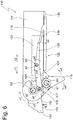
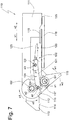
- a blade carrier 112 between an in Fig. 5 shown first rest position, one in Fig. 6 illustrated first working position, one in Fig. 7 shown second working position and one in Fig. 8 shown second rest position movable.
- the blade carrier 112 forms with the housing 111 a swivel joint G2 with a swivel axis a2.
- a blade 113 with a cutting edge 114 can be detachably fastened in the blade carrier 112.
- a blade guard 115 forms with the housing 111 a swivel joint G1 with a swivel axis a1.
- the blade guard 115 is between the in Fig. 5 shown first security position, one in Fig. 6 illustrated first cutting position, one in Fig. 7 shown second cutting position and one in Fig. 8 shown second security position pivotable.
- the blade guard 115 is moved over the cutting edge 114 such that the cutting edge is inaccessible to a user.
- the blade guard In the first cutting position, the blade guard is moved away from the cutting edge so that the cutting edge can be placed on the material to be cut and a cut can be made.
- the blade carrier 112 and the blade guard 115 are motion-coupled.
- the blade guard 115 is in the first safety position when the blade carrier 112 is arranged in the first rest position (see Fig. 5 ). If the blade carrier 112 moved into the first working position, the blade guard 115 is moved into the first cutting position (see Fig. 6 ) and when the blade carrier 112 moves to the second working position, the blade guard 115 is moved to the second cutting position (see Fig. 7 ).
- the blade guard 115 is in the second safety position when the blade carrier 112 is arranged in the second rest position (see Fig. 8 ).
- the motion coupling takes place e.g. via a toothing 116 of the blade carrier 112, which is in engagement with a toothing 117 of the blade guard 115.
- the blade carrier 112 and the blade guard 115 move in opposite directions. That is, when the blade carrier 112 pivots in the u1 direction, the blade guard 115 pivots in the w1 direction and when the blade carrier 112 pivots in the u2 direction, the blade guard 115 pivots in the w2 direction.
- a handle 118 is part of an actuating device 122 and is provided for actuating the blade carrier 112 and the blade guard 115.
- the handle 118 is between one in Fig. 5 shown unactuated position and one in Fig. 6 shown actuated position movable in directions x1 and x2.
- the handle 118 can be moved from the unactuated position in the direction x1 to the actuated position.
- the handle 118 can be moved in the direction x2 from the actuated position into the unactuated position.
- the handle is loaded, for example, by a restoring force of a spring 125, which is only indicated schematically by a dashed line, into the unactuated position.
- the spring 125 is attached to the housing 111 and to the handle 118.
- the handle could, as in the first embodiment, also be formed by a lever pivotably mounted on the housing 111.
- the handle 118 comprises a first coupling element 119 in the form of an elastically deformable arm.
- the first coupling element 119 is e.g. integrally formed on the handle 118 or connected to the handle 118.
- a free end of the first coupling element 119 can be moved into engagement with a second coupling element 120 and can also be released therefrom.
- the second coupling element 120 is formed by a region of an actuating element 121 of the actuating device 122.
- the actuating element 121 is formed by a lever which forms a swivel joint G3 with a swivel axis a3 with a guide part 123.
- the guide member 123 is movably guided in the housing 111 in the directions x1 and x2.
- the pivot axis a3 is not movable relative to the guide part 123, but is designed to be movable relative to the housing 111. According to an alternative embodiment, not shown, e.g.
- no guide part 123 is provided and a pin of the swivel joint G3 forming the pivot axis a3 is received in a link guide of the housing 111, the link guide allowing the pin to move in the direction x1 and x2 and pivoting of the actuating part 121 around the pin.
- the actuating element 121 is formed by a two-armed lever.
- the actuating element 121 comprises a first lever arm 124.
- a second lever arm forms the second coupling element 120.
- a fourth swivel joint G4 with a swivel axis a4 is formed by the actuating element 121, in particular the first lever arm 124 of the actuating element 121, and by the blade carrier 112.
- the swivel joint G4 is arranged eccentrically from the swivel axis a4 on the blade carrier 112, so that when the actuating part 121 moves in the direction x1, the blade carrier 124 is pivoted in the direction u1.
- the first coupling element 119 and the second coupling element 120 are engaged.
- the first coupling element 119 and the second coupling element 120 engage after a brief movement of the handle 118 from the unactuated position in the direction x1, while they are still disengaged in the unactuated position of the handle 118.
- the actuating element 121 and also the guide part 123 are also moved in the direction x1 via the joint G3.
- the actuating part 121 pivots the blade carrier 112 in the direction u1 into the first working position according to the joint G4 Fig. 6 , Due to the meshing teeth 116 and 117, the blade guard 115 is pivoted in a direction of rotation w1 opposite to the blade carrier 112 in the direction w1 into the first cutting position, which is shown in FIG Fig. 6 is shown.
- the actuating element 121 is also pivoted in the direction p2 by the pivoting movement of the blade carrier 112, the first coupling element 119 being deflected in the direction y1 against its elastic restoring force.
- the blade 112 is placed on the material to be cut, this results in a force F on the blade, which in accordance with the blade carrier 112 in the direction u1 in a second working position and the blade guard 115 in the direction w1 in a second cutting position Fig. 7 pivots.
- the actuating element 121 is further moved in the direction p2 into the position shown in FIG Fig. 7 pivoted, the first coupling element 119 and the second coupling element 120 being released from one another.
- the first coupling element 119 is moved back to its starting position by its elastic restoring force after releasing the coupling elements 119 and 120 in direction y2 (see Fig. 7 ).
- the blade carrier 112 which is loaded into the rest position by a spring (not shown), can pivot back in the direction u2 into the second rest position after the coupling elements 119 and 120 have been separated from one another, even if according to Fig. 8 the handle 118 is in the actuated position. Due to the movement of the blade carrier 112 in the direction u2, the blade guard 115 is pivoted in the direction w2 into the second safety position and the actuating element 121 is pivoted about the pivot axis a3 in the direction p1. In addition, the guide member 123 is moved back in the direction x2. As soon as the handle 118 is relieved of load by the user, it moves according to the spring force of the spring 125 into the unactuated position Fig. 5 , The coupling elements 119 and 120 are brought back into engagement.
Description
Die Erfindung betrifft ein Messer. Das Messer umfasst ein Gehäuse, an welchem eine Klinge gelagert ist. Die Klinge ist z.B. in einem Klingenhalter gelagert. Das Messer weist einen Klingenschutz auf, der zwischen wenigstens einer Sicherheitsposition, in welcher eine Schneide der Klinge von dem Klingenschutz verdeckt ist und mindestens einer Schneidposition, in welcher die Schneide frei zugänglich ist, bewegbar an dem Gehäuse gelagert ist.The invention relates to a knife. The knife comprises a housing on which a blade is mounted. The blade is e.g. stored in a blade holder. The knife has a blade guard which is movably mounted on the housing between at least one safety position in which a cutting edge of the blade is covered by the blade guard and at least one cutting position in which the cutting edge is freely accessible.
Ein solches Messer ist bekannt aus der
Der Klingenschutz ist durch das Aufsetzen auf dem Schneidgut aus einer aus dem Gehäuse ragenden Sicherheitsposition und einer in das Gehäuse zurückgezogenen Schneidposition schwenkbar. Der Klingenträger ist derart mit dem Klingenschutz gekoppelt, dass bei einer Bewegung des Klingenschutzes aus der Sicherheitsposition in die Schneidposition, der Klingenträger aus einer hinteren Position, in welcher eine Klinge lediglich geringfügig aus dem Gehäuse ragt, in eine vordere Position geschwenkt wird, in welcher ein Schneidvorgang möglich ist.The blade guard can be pivoted by placing it on the material to be cut from a safety position protruding from the housing and a cutting position withdrawn into the housing. The blade carrier is coupled to the blade guard in such a way that when the blade guard moves from the safety position into the cutting position, the blade carrier is pivoted from a rear position, in which a blade protrudes only slightly from the housing, into a front position, in which a Cutting process is possible.
Ein derartiges Messer ist aber mit dem Nachteil behaftet, dass der Klingenschutz auf dem zu schneidenden Material aufgesetzt werden muss, um ihn in die Schneidposition zu bewegen, was insbesondere bei empfindlichen Materialien oft unerwünscht ist.However, such a knife has the disadvantage that the blade guard is placed on the material to be cut in order to move it into the cutting position, which is often undesirable, especially with sensitive materials.
Es war Aufgabe der Erfindung ein Messer zu schaffen, welches dem Benutzer eine größere Sicherheit bietet. Es war außerdem Aufgabe der Erfindung ein Messer zu schaffen, welches auch bei empfindlichem Material einsetzbar ist. Es war überdies Aufgabe der Erfindung ein Messer zu schaffen, welches in einem vorderen Messerbereich, insbesondere dem Klingenaustrittsbereich, eine schlankere Bauweise ermöglicht.It was an object of the invention to provide a knife which offers the user greater security. It was also an object of the invention to provide a knife which can also be used with sensitive material. It was also an object of the invention to provide a knife which enables a slimmer design in a front knife area, in particular the blade exit area.
Die Erfindung wird gelöst durch ein Messer mit den Merkmalen des Anspruchs 1.The invention is achieved by a knife with the features of claim 1.
Bei dem erfindungsgemäßen Messer ist eine Betätigungsvorrichtung vorgesehen, mittels welcher der Klingenschutz zwischen der Sicherheitsposition der Schneidposition bewegbar ist. Grundsätzlich kann der Klingenschutz z. B. verschiebbar oder schwenkbar an dem Gehäuse gelagert werden, Z.B. umfasst die Betätigungsvorrichtung eine Handhabe, welche zwischen einer unbetätigten und einer betätigten Position bewegbar ist. Durch Bewegen der Handhabe der Betätigungsvorrichtung von der unbetätigten in eine betätigte Position, ist z.B der Klingenschutz aus der Sicherheitsposition in die Schneidposition bewegbar. Der Klingenschutz ist z.B. von einer Feder in die Sicherheitsposition belastet.In the knife according to the invention, an actuating device is provided, by means of which the blade guard can be moved between the safety position of the cutting position. Basically, the blade guard z. B. slidably or pivotally mounted on the housing, e.g. the actuating device comprises a handle which is movable between an unactuated and an actuated position. By moving the handle of the actuating device from the unactuated to an actuated position, the blade guard can be moved from the safety position to the cutting position, for example. The blade guard is e.g. loaded by a spring into the safety position.
Die Betätigungsvorrichtung umfasst den gesamten Antriebsstrang des Klingenschutzes. Z.B. umfasst die Betätigungsvorrichtung eine Handhabe, mittels welcher ein Benutzer des Messers den Klingenschutz betätigen kann. Die Handhabe ist z.B. zwischen einer unbetätigten und einer betätigten Position bewegbar. In der unbetätigten Position befindet sich der Klingenschutz z.B. in der Sicherheitsposition. In der betätigten Position befindet sich der Klingenschutz z.B. in einer Schneidposition. Als betätigte Position wirdnachfolgend die maximal betätigte Position der Handhabe bezeichnet. Zwischen der Handhabe und dem Klingenschutz sind z.B. ein oder mehrere Betätigungselemente ausgebildet, die miteinander bewegungsverbunden sind. Z.B. kann auch der Klingenträger teil der Betätigungsvorrichtung sein, wenn der Klingenschutz mit dem Klingenträger bewegungsverbunden ist.The actuating device comprises the entire drive train of the blade guard. For example, the actuating device comprises a handle, by means of which a user of the knife can actuate the blade guard. The handle can be moved, for example, between an unactuated and an actuated position. In the unactuated position, the blade guard is in the safety position, for example. In the actuated position, the blade guard is in a cutting position, for example. In the following, the actuated position is the maximum actuated position of the handle. Between the handle and the blade guard For example, one or more actuating elements are formed which are motionally connected to one another. For example, the blade carrier can also be part of the actuating device if the blade guard is motionally connected to the blade carrier.
In einer Sicherheitsposition ist eine Schneide der Klinge von dem Klingenschutz verdeckt. Der Klingenschutz ist dabei derart relativ zu der Schneide angeordnet, dass sich der Benutzer nicht an der Schneide verletzen kann. In der Schneidposition ist der Klingenschutz derart von der Schneide entfernt, dass ein Schneidvorgang möglich ist und der Benutzer die Klinge auf dem Schneidgut aufsetzen kann.In a safety position, a cutting edge of the blade is covered by the blade guard. The blade guard is arranged relative to the cutting edge in such a way that the user cannot injure himself on the cutting edge. In the cutting position, the blade guard is removed from the cutting edge in such a way that a cutting process is possible and the user can place the blade on the material to be cut.
Die Klinge ist z.B. lösbar in einer Klingenhalterung befestigbar. Die Klingenhalterung kann kraftschluss- und Formschlussmittel aufweisen, um die Klinge in einer bestimmten Position zu halten. Übliche Mittel sind z.B. Vorsprünge des Klingenhalters, welche in Aussparungen der Klinge eingreifen. Auch kann ein Vorsprung die Kontur der Klinge teilweise umfassen. Z.B. kann der Klingenhalter auch einen Klingensitz und eine Klappe umfassen, wobei die Klinge zwischen der Zuhaltung und der Klappe angeordnet ist.The blade is e.g. detachably attachable in a blade holder. The blade holder can have non-positive and positive locking means to hold the blade in a certain position. Common means are e.g. Projections of the blade holder, which engage in recesses in the blade. A projection can also partially encompass the contour of the blade. For example, the blade holder can also comprise a blade seat and a flap, the blade being arranged between the tumbler and the flap.
Die Klinge ist gemäß einer Ausführung unbewegbar an dem Gehäuse gehalten. D.h., dass die Klinge im montierten Zustand relativ zu dem Gehäuse unbeweglich ist. Dennoch kann sie z.B. für einen Klingenwechsel lösbar sein.According to one embodiment, the blade is held immovably on the housing. This means that the blade is immovable relative to the housing when assembled. Nevertheless, it can e.g. be detachable for a blade change.
Gemäß einer alternativen Ausführung ist die Klinge oder ein Klingenhalter zur Halterung der Klinge bewegbar an dem Gehäuse gehalten. Die Klinge kann z.B. zwischen wenigstens einer Ruheposition und wenigstens einer Arbeitsposition bewegbar sein. Die Klinge ist z.B. zwischen einer ersten und einer zweiten Ruheposition sowie einer ersten und einer zweiten Arbeitsposition bewegbar. In der Ruheposition ist die Klinge so positioniert, dass eine Schneide der Klinge von dem Klingenschutz verdeckt werden kann. Der Klingenschutz befindet sich z.B. in der Sicherheitsposition, wenn die Klinge in der Ruheposition angeordnet ist. In der Arbeitsposition der Klinge ist der Klingenschutz z.B. in der Schneidposition angeordnet.According to an alternative embodiment, the blade or a blade holder for holding the blade is movably held on the housing. The blade can, for example, be movable between at least one rest position and at least one working position. The blade can be moved, for example, between a first and a second rest position and a first and a second working position. In the rest position it is Blade positioned so that a cutting edge of the blade can be covered by the blade guard. The blade guard is, for example, in the safety position when the blade is in the rest position. In the working position of the blade, the blade guard is arranged, for example, in the cutting position.
Die Klinge oder der Klingenträger können z.B. dem Klingenschutz entgegen bewegt werden. Z.B. weisen die Klinge und der Klingenschutz unterschiedliche Schwenkrichtungen auf. Der Sicherheitszustand ist auf diese Weise schneller wiederherstellbar. Darüber hinaus ist eine geringere Bewegung des Klingenschutzes notwendig, um die Sicherheitsposition herzustellen. Auch kann z.B. auf diese Weise die Klinge zumindest teilweise in das Gehäuse des Messers verlagert werden, so dass der Klingenschutz in der Ruheposition der Klinge lediglich den Teil der Schneide abdecken muss, der aus dem Gehäuse ragt. Die Klinge oder der Klingenträger sind z.B. von einer Feder in die Ruheposition belastet.The blade or blade carrier can e.g. against the blade guard. For example, the blade and the blade guard have different pivoting directions. The security status can be restored more quickly in this way. In addition, less movement of the blade guard is necessary to establish the safety position. Also, e.g. in this way, the blade is at least partially moved into the housing of the knife, so that the blade guard in the rest position of the blade only has to cover the part of the cutting edge that protrudes from the housing. The blade or the blade carrier are e.g. loaded by a spring in the rest position.
Die Klinge kann z.B. zwischen wenigstens einer Ruheposition und wenigstens einer Arbeitsposition schwenkbar an dem Gehäuse gelagert sein. Z.B. bildet die Klinge oder ein Klingenträger mit dem Gehäuse ein Schwenkgelenk. Die Schwenkbewegung der Klinge ist z.B. kombiniert mit einer translatorischen Bewegung. Gemäß einer alternativen Ausführungsform wird die Klinge lediglich translatorisch bewegt. Mittels der schwenkbaren Klinge kann z.B. das Lösen der Kupplungselemente einer Kupplung der Betätigungsvorrichtung ausgelöst werden.The blade can e.g. be pivotally mounted on the housing between at least one rest position and at least one working position. For example, the blade or a blade carrier forms a swivel joint with the housing. The pivoting movement of the blade is e.g. combined with a translational movement. According to an alternative embodiment, the blade is only moved in translation. By means of the pivoting blade, e.g. the release of the coupling elements of a clutch of the actuating device are triggered.
Der Klingenschutz ist z.B. schwenkbar an dem Gehäuse gelagert. Z.B. bilden der Klingenschutz und das Gehäuse ein Schwenkgelenk. Die Schwenkbewegung des Klingenschutzes ist z.B. kombiniert mit einer translatorischen Bewegung. Gemäß einer alternativen Ausführung wird der Klingenschutz lediglich translatorisch bewegt.The blade guard is pivotally mounted on the housing, for example. For example, the blade guard and the housing form a swivel joint. The pivoting movement of the blade guard is combined, for example, with a translatory movement. According to an alternative embodiment, the blade guard is only moved in translation.
Die Betätigungsvorrichtung umfasst z.B. einen Exzenterantrieb. Z. B. ist ein Betätigungselement der Betätigungsvorrichtung exzentrisch, d.h. von der Schwenkachse beabstandet an der schwenkbaren Klinge oder einem schwenkbar gelagerten Klingenträger befestigt und kann die Klinge bzw. den Klingenträger rotatorisch antreiben. Gemäß einer alternativen Ausführungsform ist ein Betätigungselement der Betätigungsvorrichtung exzentrisch an einem schwenkbar gelagerten Klingenschutz befestigt, so dass der Klingenschutz auf diese Weise rotatorisch bewegbar ist.The actuator includes e.g. an eccentric drive. For example, an actuator of the actuator is eccentric, i.e. fixed at a distance from the pivot axis to the pivotable blade or a pivotably mounted blade carrier and can drive the blade or the blade carrier in rotation. According to an alternative embodiment, an actuating element of the actuating device is attached eccentrically to a pivotably mounted blade guard, so that the blade guard can be rotated in this way.
Das Messer weist z.B. eine willensunabhängige Rückbewegung des Klingenschutzes in die Sicherheitsposition auf. Die Betätigungsvorrichtung umfasst z.B. zwischen dem Klingenschutz und einer Handhabe der Betätigungsvorrichtung eine Kupplung mit einem der Handhabe zugeordneten ersten Kupplungselement und einem dem Klingenschutz zugeordneten zweiten Kupplungselement. Das erste Kupplungselement und das zweite Kupplungselement sind lösbar in Eingriff bewegbar. Das zweite Kupplungselement ist z.B. mit der Klinge bewegungsverbunden, um die Entkupplung der Kupplungselemente durch eine Bewegung der Klinge zu verursachen. Das Lösen der Kupplungselemente ermöglicht dann z.B. die Rückbewegung des Klingenschutzes, auch wenn sich die Handhabe in der betätigten Position befindet.The knife has e.g. a will-independent return of the blade guard to the safety position. The actuator includes e.g. between the blade guard and a handle of the actuating device, a clutch with a first clutch element assigned to the handle and a second clutch element assigned to the blade guard. The first coupling element and the second coupling element are releasably movable in engagement. The second coupling element is e.g. connected to the blade to cause the coupling elements to be disengaged by movement of the blade. The release of the coupling elements then enables e.g. the return movement of the blade guard, even when the handle is in the actuated position.
Um einen willensunabhängigen Rückzug des Klingenschutzes in die Sicherheitsposition vorzusehen, weist das Messer gemäß einer alternativen Ausführung eine andere Kupplung auf. Die Kupplung umfasst dabei ein der Betätigungsvorrichtung oder dem Klingenschutz zugeordnetes erstes Kupplungselement und ein dem Gehäuse zugeordnetes zweites Kupplungselement. Das erste Kupplungselement und das zweite Kupplungselement sind auch bei dieser Ausführungsform lösbar in Eingriff bewegbar. Das erste Kupplungselement ist z.B. mit der Klinge bewegungsverbunden, um die Entkupplung der Kupplungselemente durch eine Bewegung der Klinge zu verursachen. Das Lösen der Kupplungselemente ermöglicht auch in diesem Fall die Rückbewegung des Klingenschutzes, auch wenn sich die Handhabe in der betätigten Position befindet.In order to provide for a retraction of the blade guard into the safety position independent of the will, the knife has a different coupling according to an alternative embodiment. The coupling comprises a first coupling element assigned to the actuating device or the blade guard and a second coupling element assigned to the housing. The first coupling element and the second coupling element are also releasably movable in engagement in this embodiment. The first coupling element is, for example, motionally connected to the blade in order to cause the coupling elements to be uncoupled by a movement of the blade. The In this case as well, releasing the coupling elements enables the blade guard to move back, even when the handle is in the actuated position.
Das erste Kupplungselement und das zweite Kupplungselement sind z.B. durch eine Bewegung der Klinge von einer ersten Arbeitsposition in eine zweite Arbeitsposition bewegbar. Z.B. ist eines der Kupplungselemente derart mit der Klinge verbunden, dass die Bewegung der Klinge die Kupplungselemente außer Eingriff versetzt.The first coupling element and the second coupling element are e.g. movable by moving the blade from a first working position to a second working position. For example, one of the coupling elements is connected to the blade such that the movement of the blade disengages the coupling elements.
Z.B. kann die Entkupplung gemäß einer anderen Ausführungsform dadurch stattfinden, dass durch eine starke Beschleunigung, die beim Abrutschen von dem Schneidgut auftritt, eine Schwungmasse der Kupplung bewegt wird. Das Bewegen der Schwungmasse versetzt die Kupplungselemente außer Eingriff. Gemäß einer alternativen Ausführung könnten die Kupplungselemente durch eine Schneidkraft, die auf die Klinge wirkt und eine Bewegung des Klingenträgers verursacht, außer Eingriff gebracht werden.For example, According to another embodiment, the uncoupling can take place in that a flywheel mass of the coupling is moved by a strong acceleration that occurs when the material to be cut slips off. Moving the flywheel disengages the coupling elements. According to an alternative embodiment, the coupling elements could be disengaged by a cutting force which acts on the blade and causes the blade carrier to move.
Die Betätigungsvorrichtung ist z.B. derart ausgebildet, dass der Klingenschutz bei der Bewegung in die Sicherheitsposition frontal auf eine mit der Schneide versehene Seite der Klinge zugeschwenkt wird. Bei der Bewegung in die Sicherheitsposition verdeckt der Klingenschutz also zuerst die Schneide der Klinge. Das hat den Vorteil, dass der Klingenschutz die Sicherheit des Messers sehr schnell wieder herstellen kann. Wenn der Klingenschutz von einer der Schneide gegenüberliegenden Seite kommend über die Schneide bewegt wird, dauert die Herstellung der Sicherheit des Messers länger.The actuator is e.g. designed in such a way that the blade guard is pivoted towards a side of the blade provided with the cutting edge when moving into the safety position. When moving to the safety position, the blade guard first covers the cutting edge of the blade. This has the advantage that the blade guard can restore the safety of the knife very quickly. If the blade guard is moved over the cutting edge from a side opposite the cutting edge, the safety of the knife takes longer to be established.
Weitere Vorteile der Erfindung ergeben sich anhand der Beschreibung eines in den Fig. dargestellten Ausführungsbeispiels. Es zeigen:
-
Fig. 1 eine schematische Schnittdarstellung einer ersten Ausführungsform des Messers mit starr an dem Gehäuse befestigter Klinge, wobei die Handhabe unbetätigt ist und der Klingenschutz in einer Sicherheitsposition angeordnet ist, -
Fig. 2 in Anlehnung anFig. 1 das Messer, wobei die Handhabe sich in einer betätigten Position befindet und der Klingenschutz in einer Schneidposition angeordnet ist, -
Fig. 3 , in Anlehnung anFig. 2 das Messer, wobei die Kupplungselemente einer Betätigungsvorrichtung voneinander getrennt sind, -
Fig. 4 , in Anlehnung anFig. 3 das Messer, wobei sich die Handhabe in der betätigten Position befindet und der Klingenschutz in die Sicherheitsposition bewegt ist, -
Fig. 5 eine zweite Ausführungsform des Messers mit bewegbar an dem Gehäuse gelagerter Klinge, wobei der Klingenschutz in der Sicherheitsposition und die Klinge in einer Ruheposition angeordnet ist, -
Fig. 6 in Anlehnung anFig. 5 das Messer, wobei die Handhabe sich in einer betätigten Position befindet, der Klingenschutz in einer ersten Schneidposition und die Klinge in einer ersten Arbeitsposition angeordnet ist, -
Fig. 7 in Anlehnung anFig. 6 das Messer, wobei die Handhabe sich in der betätigten Position befindet, der Klingenschutz in einer zweiten Schneidposition und die Klinge in einer zweiten Arbeitsposition angeordnet ist und wobei die Kupplungselemente einer Betätigungsvorrichtung voneinander getrennt sind, -
Fig. 8 das Messer in Anlehnung anFig. 7 , wobei sich die Handhabe in der betätigten Position befindet und der Klingenschutz in die Sicherheitsposition bewegt ist.
-
Fig. 1 2 shows a schematic sectional illustration of a first embodiment of the knife with a blade rigidly fastened to the housing, the handle being unactuated and the blade guard being arranged in a safety position, -
Fig. 2 based onFig. 1 the knife, wherein the handle is in an actuated position and the blade guard is arranged in a cutting position, -
Fig. 3 , based onFig. 2 the knife, the coupling elements of an actuating device being separated from one another, -
Fig. 4 , based onFig. 3 the knife, with the handle in the actuated position and the blade guard moved to the safety position, -
Fig. 5 A second embodiment of the knife with a blade movably mounted on the housing, the blade guard being arranged in the safety position and the blade in a rest position. -
Fig. 6 based onFig. 5 the knife, the handle being in an actuated position, the blade guard in a first cutting position and the blade in a first working position, -
Fig. 7 based onFig. 6 the knife, with the handle being in the actuated position, the blade guard in a second cutting position and the blade in a second working position, and with the coupling elements of an actuating device being separated from one another, -
Fig. 8 the knife based onFig. 7 , the handle being in the actuated position and the blade guard being moved to the safety position.
Das Messer gemäß der ersten Ausführungsform insgesamt wird in den
Das Messer 10 umfasst gemäß
Ein Klingenschutz 14 ist um eine Schwenkachse a1 zwischen einer Sicherheitsposition und einer Schneidposition schwenkbar an dem Gehäuse 11 gelagert und bildet mit dem Gehäuse 11 ein Schwenkgelenk G1. Der Klingenschutz 14 ist bügelförmig ausgebildet und umschließt in der in
Eine Handhabe 15 ist um eine Schwenkachse a2 zwischen einer unbetätigten Position und einer betätigten Position schwenkbar an dem Gehäuse 11 gelagert und bildet mit dem Gehäuse 11 ein Schwenkgelenk G2. Als "betätigte Position" wird nachfolgend die maximal betätigte Position der Handhabe gemäß der
Im vorliegenden Ausführungsbeispiel ist die Handhabe 15 von einem schwenkbar an dem Gehäuse 11 gelagerten Hebel gebildet, wobei es darauf aber bei der Erfindung nicht ankommt. Vielmehr könnte die Handhabe 15 gemäß einer alternativen Ausführung auch von einem Schieber gebildet sein.In the present exemplary embodiment, the
Die Handhabe 15 umfasst einen Fortsatz 17 mit einem Nocken 18. Der Nocken 18 steht in Kontakt mit einer zu der Bewegungsrichtung x1, x2 geneigten Schrägfläche 19 eines Schlittens 20. Der Schlitten 20 ist in die Richtungen x1 und x2 zwischen einer hinteren Position und einer vorderen Position bewegbar in dem Gehäuse 11 gelagert. Eine Feder 21, die mit einem Ende an dem Schlitten 20 und mit dem anderen Ende an dem Gehäuse 11 befestigt ist, belastet den Schlitten 20 in eine in
Ein Kupplungshebel 22 ist um eine Schwenkachse a3 zwischen einer Eingriffsposition und einer Löseposition schwenkbar an dem Schlitten 20 gelagert und bildet mit dem Schlitten 20 ein Schwenkgelenk G3. Von einer Feder 27, die mit einem Ende an dem Gehäuse 11 und mit einem anderen Ende an dem Kupplungshebel 22 befestigt ist, ist der Kupplungshebel 22 in die Eingriffsposition gemäß
Der erste Kupplungsvorsprung 25 steht in Eingriff mit einem zweiten Kupplungsvorsprung 28 eines Kupplungsschlittens 29. Die Kupplungsvorsprünge 25 und 28 bilden eine Kupplung 38. In der Eingriffsposition ist der Kupplungshebel 22 derart angeordnet, dass der erste Kupplungsvorsprung 25 in Eingriff mit dem zweiten Kupplungsvorsprung versetzbar ist. In der Löseposition sind die Kupplungsvorsprünge 25 und 28 außer Eingriff.The
Der Kupplungsschlitten 29 ist in die Richtungen x1 und x2 zwischen einer rückwärtigen Position und einer vorgeschobenen Position bewegbar in dem Gehäuse 11 gelagert. Eine Feder 30, die mit einem Endbereich an dem Gehäuse und mit einem anderen Endbereich an dem Kupplungsschlitten 29 befestigt ist, belastet den Kupplungsschlitten 29 in die rückwärtige Position.The
Ein erster Endbereich 31 eines Lenkers 32 bildet mit dem Kupplungsschlitten 29 ein Schwenkgelenk G4 mit der Schwenkachse a4. Ein zweiter Endbereich 33 des Lenkers 32 bildet mit einem an dem Klingenschutz 14 befestigten Hebelarm 34 ein Schwenkgelenk G5 mit der Schwenkachse a5.A
Um einen Schneidvorgang durchzuführen, wird die Handhabe 15 aus der unbetätigten Position gemäß
Wenn der Kupplungsschlitten 29 in die vorgeschobene Position verlagert wird, bewegt er über den Lenker 32 und den Hebelarm 34 den Klingenschutz 14 in Richtung w1 in die Schneidposition (siehe
Das Messer 10 verfügt über eine willensunabhängige Klingenschutz-Rückbewegung. Sollte der Benutzer beim Schneiden vom Schneidgut abrutschen, so wird durch die ruckartige Bewegung nach unten in Richtung z der Kupplungshebel 22 aufgrund der Massenträgheit entgegen der Federkraft der Feder 27 in Richtung v1 geschwenkt, wobei sich der erste Kupplungsvorsprung 25 und der zweite Kupplungsvorsprung 28 außer Eingriff bewegen (siehe
Bei nachlassender Kraft auf die Handhabe 15 wird der Schlitten 20 von der Feder 21 in die hintere Position zurückverlagert und indirekt wird dabei auch die Handhabe 15 in Richtung u2 in die unbetätigte Position bewegt. Der erste Kupplungsvorsprung 25 des Kupplungshebels 22, welcher von der Feder 27 in Richtung v2 belastet ist, bewegt sich wieder in Eingriff mit dem zweiten Kupplungsvorsprung 28 des Kupplungsschlittens 29 (siehe
Eine zweite Ausführungsform des Messers ist in den
Das Messer 110 umfasst ein Gehäuse 111. An dem Gehäuse 111 ist ein Klingenträger 112 zwischen einer in
Ein Klingenschutz 115 bildet mit dem Gehäuse 111 ein Schwenkgelenk G1 mit einer Schwenkachse a1. Der Klingenschutz 115 ist zwischen der in
Der Klingenträger 112 und der Klingenschutz 115 sind bewegungsgekoppelt. Der Klingenschutz 115 befindet sich in der ersten Sicherheitsposition, wenn der Klingenträger 112 in der ersten Ruheposition angeordnet ist (siehe
Die Bewegungskopplung erfolgt z.B. über eine Verzahnung 116 des Klingenträgers 112, welche in Eingriff steht mit einer Verzahnung 117 des Klingenschutzes 115. Auf diese Weise bewegen sich der Klingenträger 112 und der Klingenschutz 115 gegenläufig. D.h., wenn der Klingenträger 112 in Richtung u1 schwenkt, schwenkt der Klingenschutz 115 in Richtung w1 und wenn der Klingenträger 112 in Richtung u2 schwenkt, schwenkt der Klingenschutz 115 in Richtung w2.The motion coupling takes place e.g. via a
Eine Handhabe 118 ist Teil einer Betätigungsvorrichtung 122 und zur Betätigung des Klingenträgers 112 sowie des Klingenschutzes 115 vorgesehen. Die Handhabe 118 ist zwischen einer in
Gemäß einer alternativen, nicht dargestellten Ausführungsform könnte die Handhabe, wie bei dem ersten Ausführungsbeispiel, auch von einem an dem Gehäuse 111 schwenkbar gelagerten Hebel gebildet sein.According to an alternative embodiment, not shown, the handle could, as in the first embodiment, also be formed by a lever pivotably mounted on the
Die Handhabe 118 umfasst ein erstes Kupplungselement 119 in Form eines elastisch verformbaren Arms. Das erste Kupplungselement 119 ist z.B. an der Handhabe 118 angeformt oder mit der Handhabe 118 verbunden. Ein freies Ende des ersten Kupplungselements 119 kann in Eingriff mit einem zweiten Kupplungselement 120 bewegt werden und von diesem auch wieder gelöst werden. Das zweite Kupplungselement 120 ist von einem Bereich eines Betätigungselements 121 der Betätigungsvorrichtung 122 gebildet.The
Das Betätigungselement 121 ist von einem Hebel gebildet, welcher ein Schwenkgelenk G3 mit einer Schwenkachse a3 mit einem Führungsteil 123 bildet. Das Führungsteil 123 ist in dem Gehäuse 111 in die Richtungen x1 und x2 bewegbar geführt. Die Schwenkachse a3 ist relativ zu dem Führungsteil 123 nicht bewegbar, aber relativ zu dem Gehäuse 111 bewegbar ausgebildet. Gemäß einer alternativen, nicht dargestellten Ausführungsform ist z.B. kein Führungsteil 123 vorgesehen und ein die Schwenkachse a3 bildender Zapfen des Schwenkgelenks G3 ist in einer Kulissenführung des Gehäuses 111 aufgenommen, wobei die Kulissenführung eine Bewegung des Zapfens in Richtung x1 und x2 sowie ein Schwenken des Betätigungsteils 121 um den Zapfen gestattet.The
Das Betätigungselement 121 ist in dem vorliegenden Ausführungsbeispiel von einem zweiarmigen Hebel gebildet. Das Betätigungselement 121 umfasst einen ersten Hebelarm 124. Ein zweiter Hebelarm bildet das zweite Kupplungselement 120 aus. Ein viertes Schwenkgelenk G4 mit einer Schwenkachse a4 ist von dem Betätigungselement 121, insbesondere dem ersten Hebelarm 124 des Betätigungselements 121, und von dem Klingenträger 112 gebildet. Das Schwenkgelenk G4 ist exzentrisch von der Schwenkachse a4 an dem Klingenträger 112 angeordnet, so dass bei einer Bewegung des Betätigungsteils 121 in Richtung x1 der Klingenträger 124 in Richtung u1 geschwenkt wird.In the present exemplary embodiment, the
In der Ausgangsposition des Messers gemäß
Wenn der Benutzer die Handhabe aus der in
Wird die Klinge 112 auf dem Schneidgut aufgesetzt, resultiert daraus eine Kraft F auf die Klinge, welche den Klingenträger 112 in Richtung u1 in eine zweite Arbeitsposition und den Klingenschutz 115 in Richtung w1 in eine zweite Schneidposition gemäß
Der Klingenträger 112, welcher von einer nicht dargestellten Feder in die Ruheposition belastet ist, kann nachdem die Kupplungselemente 119 und 120 voneinander getrennt wurden, in Richtung u2 in die zweite Ruheposition zurückschwenken, auch wenn sich gemäß
Claims (12)
- A knife comprising a housing (11) on which a blade (12, 113) is mounted and a blade guard (14, 115) pivotably mounted on the housing (11), which is biased by a spring into the safety position, whereby the blade guard (14, 115) is movable by an actuator (16, 122) comprising a handle (15) between a safety position in which a cutting edge (13, 114, of the blade (12, 113) is covered by the blade guard (14, 115) and a cutting position in which the cutting edge (13, 114) is freely accessible, characterized in that, the actuator (16, 122) is designed in such a way that, during the movement into the safety position, the blade guard (14, 115) is pivoted forward toward a side (37) of the blade (12, 113) provided with the cutting edge (13, 114).
- The knife according to claim 1, characterized in that the blade (12) is immovably fixed on the housing (11, 111).
- The knife according to claim 1, characterized in that the blade (12, 113) is movable on the housing (11, 111).
- The knife according to claim 3, characterized in that the blade (12, 113) is pivotal on the housing (11, 111) between at least one rest position and at least one cutting position.
- The knife according to claim 3, characterized in that the blade is slidable on the housing (11, 111).
- Knife according to claim 4, characterized in that the blade (113) is biased by a spring into the rest position.
- The knife according to one of the preceding claims, characterized in that the actuator (16, 122) has an eccentric drive.
- The knife according to one of the preceding claims, characterized in that the blade (12, 113) is held in a blade holder (112).
- The knife according to one of the preceding claims, characterized in that the actuator (16, 122) has, between the blade guard (14, 115) and a handle (15, 118) of the actuator (16, 122), a coupling (38) with a coupling element (28,120) associated with the blade guard (14, 115) and a coupling element (25, 119) associated with the handle (15, 118).
- The knife according to one of the claims 1 to 8, characterized in that the actuator (16, 122) has a coupling (38) with a coupling element associated with the actuator (16) or the blade guard, and a coupling element associated with the housing (11).
- The knife according to one of the claims 9 or 10, characterized in that the coupling elements (25, 28, 119, 120) can be moved out of the engagement with each other by movement of the blade (113) from a first cutting position into a second cutting position.
- The knife according to one of the claims 9 to 11, characterized in that the coupling elements (25, 28, 119, 120) can be moved out of engagement with each other by movement of an inertia mass (24) movably connected to one of the coupling elements (25).
Applications Claiming Priority (2)
| Application Number | Priority Date | Filing Date | Title |
|---|---|---|---|
| DE102013014684.4A DE102013014684A1 (en) | 2013-09-05 | 2013-09-05 | knife |
| PCT/DE2014/000451 WO2015032380A1 (en) | 2013-09-05 | 2014-09-05 | Knife |
Publications (2)
| Publication Number | Publication Date |
|---|---|
| EP3041646A1 EP3041646A1 (en) | 2016-07-13 |
| EP3041646B1 true EP3041646B1 (en) | 2020-03-04 |
Family
ID=51690778
Family Applications (1)
| Application Number | Title | Priority Date | Filing Date |
|---|---|---|---|
| EP14783763.7A Active EP3041646B1 (en) | 2013-09-05 | 2014-09-05 | Knife |
Country Status (6)
| Country | Link |
|---|---|
| US (1) | US10994434B2 (en) |
| EP (1) | EP3041646B1 (en) |
| CN (1) | CN105682869B (en) |
| DE (1) | DE102013014684A1 (en) |
| ES (1) | ES2787210T3 (en) |
| WO (1) | WO2015032380A1 (en) |
Families Citing this family (7)
| Publication number | Priority date | Publication date | Assignee | Title |
|---|---|---|---|---|
| DE202013007112U1 (en) * | 2013-08-09 | 2014-11-13 | Martor Kg | knife |
| DE102016008724A1 (en) * | 2016-07-21 | 2018-01-25 | Martor Kg | knife |
| US10207414B2 (en) * | 2016-11-17 | 2019-02-19 | Goodrich Corporation | Safety knife with retractable sheath |
| DE102018117203B4 (en) * | 2018-07-17 | 2024-02-01 | Martor Kg | Knife |
| DE102019001280A1 (en) * | 2019-02-23 | 2020-08-27 | Martor Kg | knife |
| US11254020B2 (en) * | 2019-12-11 | 2022-02-22 | Tsang Wing WONG | Safety cutter |
| US11919179B2 (en) | 2020-03-31 | 2024-03-05 | Aob Products Company | Out-the-front knife |
Family Cites Families (81)
| Publication number | Priority date | Publication date | Assignee | Title |
|---|---|---|---|---|
| US365714A (en) * | 1887-06-28 | Simon p | ||
| DE1121972B (en) * | 1962-01-11 | |||
| US1299084A (en) * | 1918-08-06 | 1919-04-01 | Swift & Co | Gutter's knife. |
| US1452893A (en) * | 1922-05-10 | 1923-04-24 | Swift & Co | Attachment for skinning knives |
| US2209751A (en) * | 1937-09-11 | 1940-07-30 | Western Electric Co | Cutting tool |
| US2376887A (en) * | 1944-06-15 | 1945-05-29 | Waltern Lewis | Package cutter |
| US2730800A (en) * | 1954-06-28 | 1956-01-17 | Russell L Bailey | Safety paper box cutter |
| US2743523A (en) * | 1955-06-27 | 1956-05-01 | Honey Robert | Carton opening knife |
| US3430339A (en) * | 1967-05-16 | 1969-03-04 | Robert H Hobson | Case cutter |
| US3781988A (en) * | 1972-08-29 | 1974-01-01 | R Jones | Safety paper carton opening blade holder |
| US4086698A (en) * | 1977-02-28 | 1978-05-02 | Macfield Texturing, Inc. | Safety guard for the blade of carton openers |
| US4091537A (en) * | 1977-04-26 | 1978-05-30 | Stevenson Machine Shop | Safety utility knife |
| US4157616A (en) * | 1977-12-20 | 1979-06-12 | Lundqvist Karl G | Hand tools |
| US4531286A (en) * | 1983-02-08 | 1985-07-30 | Vito Raymond P | Carton cutting knife |
| US4757612A (en) * | 1985-03-21 | 1988-07-19 | Preposreve S.A.R.L. | Fixed-blade knife with retractable blade cover |
| US4980977A (en) * | 1987-12-14 | 1991-01-01 | The Boeing Company | Safety core cutting knife |
| DE8902653U1 (en) * | 1989-03-06 | 1989-04-13 | Siep, Ewald, 5000 Koeln, De | |
| US4987682A (en) * | 1989-07-17 | 1991-01-29 | Minnick Debra K | Safety device for utility knives and the like |
| US5116351A (en) * | 1989-10-11 | 1992-05-26 | Frassetti Paris R | Safety scalpel |
| US5241750A (en) * | 1992-04-30 | 1993-09-07 | Chomiak Bryant D | Utility razor safety knife |
| US5250064A (en) * | 1992-10-07 | 1993-10-05 | Biological Tissue Reserve, Inc. | Shield for surgical scalpel blades |
| GB9223942D0 (en) * | 1992-11-14 | 1993-01-06 | Granton Ragg Limited | Scalpel |
| US5330494A (en) * | 1993-01-22 | 1994-07-19 | Cornelis A. van der Westhuizen | Knife |
| US5522135A (en) * | 1994-09-06 | 1996-06-04 | Spellbound Development Group | Box opener |
| US5522828A (en) * | 1994-11-08 | 1996-06-04 | Malilay; Cicero H. | Surgical knife with blade shield |
| US5581893A (en) * | 1995-09-25 | 1996-12-10 | Ouellette; Shawn | Protective guard for a utility knife |
| US5676677A (en) * | 1996-03-21 | 1997-10-14 | Landis; Robert M. | Guard for the blade of a knife |
| US5697157A (en) * | 1996-09-13 | 1997-12-16 | Spellbound Development Group | Heavy-duty box opener |
| US5852874A (en) * | 1997-02-19 | 1998-12-29 | Walker; Henry F. | Carton cutting device having a pivotal guard member |
| US5890290A (en) * | 1997-08-05 | 1999-04-06 | Davis; Raymond E. | Adjustable depth safety cutter |
| US6233832B1 (en) * | 1998-06-11 | 2001-05-22 | Martor-Argentax E.H. Beermann Kg | Razor knife with retractable and latchable blade guard |
| JP2899591B1 (en) * | 1998-06-12 | 1999-06-02 | オルファ株式会社 | Lockable grip cutter knife |
| US6070326A (en) * | 1999-06-11 | 2000-06-06 | Martor-Argentax E.H. Beermann Kg | Razor knife with retractable blade guard |
| US6178640B1 (en) * | 1999-08-09 | 2001-01-30 | Spellbound Development Group, Inc. | Slitter device |
| US6560873B1 (en) * | 1999-11-12 | 2003-05-13 | Mel Wayne Ortner | Automatic safety knife |
| US6327783B1 (en) * | 2000-03-20 | 2001-12-11 | Chen Shan Ming | Rotating and locating structures of protective shield of round knife |
| US6578266B2 (en) * | 2000-12-07 | 2003-06-17 | Bryant D. Chomiak | Safety utility razor knife |
| US20020124412A1 (en) * | 2001-03-12 | 2002-09-12 | Votolato Earl J. | Utility knife tool with cover lock |
| US7485126B2 (en) | 2001-05-09 | 2009-02-03 | New York University | Scalpel blade guard |
| US7024772B1 (en) * | 2001-11-21 | 2006-04-11 | Specmaster Inc. | Case knife with multiple position blade guards |
| US6643936B2 (en) * | 2002-01-17 | 2003-11-11 | Alterra Holdings Corporation | Hand-held rotary cutter |
| AU2003285070A1 (en) * | 2002-10-28 | 2004-05-25 | Acme United Corporation | Rotary trimmer |
| US7509742B2 (en) * | 2002-11-19 | 2009-03-31 | Earl & Kimberly Votolato, Trustees Of The Votolato Living Trust | Safety cutting apparatus |
| US6748659B1 (en) * | 2002-11-20 | 2004-06-15 | Raymond L. Street | Safety knife construction |
| US7082688B2 (en) * | 2003-10-28 | 2006-08-01 | Earl J. Votolato | Utility knife with dual retractable cutting guides |
| US8347509B2 (en) * | 2004-04-05 | 2013-01-08 | Votolato Living Trust | Utility tool having interchangeable tool cartridges |
| US8099868B1 (en) * | 2004-04-05 | 2012-01-24 | Votolato Living Trust | Disposable blade cartridge utility knife |
| US7475480B2 (en) * | 2004-04-05 | 2009-01-13 | The Votolato Living Trust | Disposable blade cartridge utility knife |
| US7356928B2 (en) * | 2004-09-08 | 2008-04-15 | Earl J. & Kimberly Votolato Trustees Of The Votolato Living Trust | Utility knife with safety guard having reduced play |
| US7204023B2 (en) * | 2004-12-30 | 2007-04-17 | Pi-Chao Chang | Rotary cutter |
| US7213284B2 (en) * | 2005-05-03 | 2007-05-08 | Te-Ming Huang | Optic disk pack opener |
| US7810241B2 (en) * | 2006-05-23 | 2010-10-12 | Pooler Jason C | Shielded scalpel |
| US20080010839A1 (en) * | 2006-07-13 | 2008-01-17 | Fiskars Brands, Inc. | Handheld rotary cutter |
| US7774942B2 (en) * | 2006-10-09 | 2010-08-17 | Pacific Handy Cutter, Inc. | Utility knife |
| US8122605B2 (en) | 2007-01-09 | 2012-02-28 | Earl Votolato | Utility knife with counter-reciprocating blade and guard |
| EP1982802B1 (en) * | 2007-04-16 | 2011-06-29 | Adco Industries, a subsidiary of Dallco Marketing, Inc. | Cutting rigid and semi-rigid material |
| US20090094839A1 (en) * | 2007-10-11 | 2009-04-16 | Earl Votolato | Electronic Utility Knife with Safety Reaction System |
| US8117754B2 (en) * | 2007-10-19 | 2012-02-21 | Mastrad, S.A. | Fixed-blade knife having a multi-purpose guard |
| US8046922B2 (en) * | 2008-01-18 | 2011-11-01 | Fiskars Brands, Inc. | Cutting device |
| DE102008019441A1 (en) * | 2008-04-17 | 2009-10-22 | Martor Kg | knife |
| EP2203281B2 (en) * | 2008-01-31 | 2015-05-27 | Martor Kg | Knife |
| US8732957B2 (en) * | 2008-04-17 | 2014-05-27 | Martor Kg | Retractile-blade utility knife |
| US8127452B2 (en) * | 2009-02-26 | 2012-03-06 | Pacific Handy Cutter, Inc. | Utility knife |
| US8307556B2 (en) * | 2009-06-19 | 2012-11-13 | ADCO Industries—Technologies, L.P. | Utility cutter |
| USD644493S1 (en) * | 2010-05-10 | 2011-09-06 | Mastrad, S.A. | Knife with a folding guard |
| DE102010023680A1 (en) * | 2010-06-14 | 2011-12-15 | Martor Kg | knife |
| EP2529900B1 (en) * | 2011-06-01 | 2015-09-09 | JT International S.A. | Grip-type cutter knife |
| US8732956B2 (en) * | 2011-06-15 | 2014-05-27 | Aaron Paul McGushion | Safety locking mechanism for a utility knife |
| US8720068B2 (en) * | 2012-01-19 | 2014-05-13 | Ritesafety Products International, Llc | Hand cutter with blade guard |
| US9003668B2 (en) * | 2012-10-18 | 2015-04-14 | Ritesafety Products International, Llc | Hand cutter with blade guard |
| DE202013007112U1 (en) * | 2013-08-09 | 2014-11-13 | Martor Kg | knife |
| US9027254B1 (en) * | 2013-11-08 | 2015-05-12 | Bosela Design LLC | Scalpel handle having a blade shield |
| DE102015005768A1 (en) * | 2015-05-08 | 2016-11-10 | Martor Kg | knife |
| US10315325B2 (en) * | 2015-11-03 | 2019-06-11 | Spellbound Development Group, Inc. | Blade cartridges and lockable safety covers |
| US10315317B2 (en) * | 2015-11-03 | 2019-06-11 | Spellbound Development Group, Inc. | Blade cartridges and lockable safety covers |
| US20170274544A1 (en) * | 2016-03-24 | 2017-09-28 | Ty Stiles | Cutting Tool |
| US10300615B2 (en) * | 2016-04-06 | 2019-05-28 | Earl Votolato | Utility knife with improved safety features |
| USD865479S1 (en) * | 2017-10-18 | 2019-11-05 | Martor Kg | Utility knife |
| DE102018117203B4 (en) * | 2018-07-17 | 2024-02-01 | Martor Kg | Knife |
| DE102019001280A1 (en) * | 2019-02-23 | 2020-08-27 | Martor Kg | knife |
| EP3698928B1 (en) * | 2019-02-23 | 2024-03-13 | Martor KG | Knife with blade device |
-
2013
- 2013-09-05 DE DE102013014684.4A patent/DE102013014684A1/en not_active Ceased
-
2014
- 2014-09-05 WO PCT/DE2014/000451 patent/WO2015032380A1/en active Application Filing
- 2014-09-05 EP EP14783763.7A patent/EP3041646B1/en active Active
- 2014-09-05 ES ES14783763T patent/ES2787210T3/en active Active
- 2014-09-05 CN CN201480057567.0A patent/CN105682869B/en active Active
- 2014-09-05 US US14/915,541 patent/US10994434B2/en active Active
Non-Patent Citations (1)
| Title |
|---|
| None * |
Also Published As
| Publication number | Publication date |
|---|---|
| WO2015032380A1 (en) | 2015-03-12 |
| CN105682869A (en) | 2016-06-15 |
| CN105682869B (en) | 2018-07-31 |
| EP3041646A1 (en) | 2016-07-13 |
| ES2787210T3 (en) | 2020-10-15 |
| DE102013014684A1 (en) | 2015-03-05 |
| US20160229074A1 (en) | 2016-08-11 |
| US10994434B2 (en) | 2021-05-04 |
Similar Documents
| Publication | Publication Date | Title |
|---|---|---|
| EP3041646B1 (en) | Knife | |
| EP2203281B1 (en) | Knife | |
| EP2965879B1 (en) | Knife | |
| EP3030385B1 (en) | Knife | |
| EP2511056B1 (en) | Safety knife | |
| EP2716420B1 (en) | Knife | |
| DE60101654T2 (en) | Cutter with automatically retractable blade | |
| DE102007052060A1 (en) | knife | |
| EP2394801B1 (en) | Knife | |
| EP2631116B1 (en) | Headrest | |
| DE102016008724A1 (en) | knife | |
| EP2703133B1 (en) | Knife | |
| DE102018117203B4 (en) | Knife | |
| EP2942164B1 (en) | Knife with automatic blade return | |
| DE112013006427T5 (en) | Foldable headrest construction | |
| EP3590760B1 (en) | Headrest | |
| EP2527101B1 (en) | Cutting set holder | |
| DE102008007090B3 (en) | Craft knife designed for safe operation, has blade carrier swinging about axis fixed relative to casing, with spring bias for safe retraction after cutting | |
| EP3470185A1 (en) | Knife | |
| DE102009050380A1 (en) | knife | |
| DE202014100138U1 (en) | Rigid lockable secateurs | |
| EP2566668B1 (en) | Knife | |
| DE202008005369U1 (en) | knife | |
| EP2890531B1 (en) | Cutting device | |
| DE102019001283A1 (en) | knife |
Legal Events
| Date | Code | Title | Description |
|---|---|---|---|
| PUAI | Public reference made under article 153(3) epc to a published international application that has entered the european phase |
Free format text: ORIGINAL CODE: 0009012 |
|
| 17P | Request for examination filed |
Effective date: 20160304 |
|
| AK | Designated contracting states |
Kind code of ref document: A1 Designated state(s): AL AT BE BG CH CY CZ DE DK EE ES FI FR GB GR HR HU IE IS IT LI LT LU LV MC MK MT NL NO PL PT RO RS SE SI SK SM TR |
|
| AX | Request for extension of the european patent |
Extension state: BA ME |
|
| DAX | Request for extension of the european patent (deleted) | ||
| STAA | Information on the status of an ep patent application or granted ep patent |
Free format text: STATUS: EXAMINATION IS IN PROGRESS |
|
| 17Q | First examination report despatched |
Effective date: 20181115 |
|
| REG | Reference to a national code |
Ref country code: DE Ref legal event code: R079 Ref document number: 502014013765 Country of ref document: DE Free format text: PREVIOUS MAIN CLASS: B26B0029020000 Ipc: B26B0005000000 |
|
| GRAP | Despatch of communication of intention to grant a patent |
Free format text: ORIGINAL CODE: EPIDOSNIGR1 |
|
| STAA | Information on the status of an ep patent application or granted ep patent |
Free format text: STATUS: GRANT OF PATENT IS INTENDED |
|
| RIC1 | Information provided on ipc code assigned before grant |
Ipc: B26B 5/00 20060101AFI20190925BHEP Ipc: B26B 29/02 20060101ALI20190925BHEP |
|
| INTG | Intention to grant announced |
Effective date: 20191010 |
|
| GRAS | Grant fee paid |
Free format text: ORIGINAL CODE: EPIDOSNIGR3 |
|
| GRAA | (expected) grant |
Free format text: ORIGINAL CODE: 0009210 |
|
| STAA | Information on the status of an ep patent application or granted ep patent |
Free format text: STATUS: THE PATENT HAS BEEN GRANTED |
|
| AK | Designated contracting states |
Kind code of ref document: B1 Designated state(s): AL AT BE BG CH CY CZ DE DK EE ES FI FR GB GR HR HU IE IS IT LI LT LU LV MC MK MT NL NO PL PT RO RS SE SI SK SM TR |
|
| REG | Reference to a national code |
Ref country code: GB Ref legal event code: FG4D Free format text: NOT ENGLISH |
|
| REG | Reference to a national code |
Ref country code: CH Ref legal event code: EP |
|
| REG | Reference to a national code |
Ref country code: AT Ref legal event code: REF Ref document number: 1239851 Country of ref document: AT Kind code of ref document: T Effective date: 20200315 |
|
| REG | Reference to a national code |
Ref country code: DE Ref legal event code: R096 Ref document number: 502014013765 Country of ref document: DE |
|
| REG | Reference to a national code |
Ref country code: IE Ref legal event code: FG4D Free format text: LANGUAGE OF EP DOCUMENT: GERMAN |
|
| REG | Reference to a national code |
Ref country code: NL Ref legal event code: FP |
|
| PG25 | Lapsed in a contracting state [announced via postgrant information from national office to epo] |
Ref country code: FI Free format text: LAPSE BECAUSE OF FAILURE TO SUBMIT A TRANSLATION OF THE DESCRIPTION OR TO PAY THE FEE WITHIN THE PRESCRIBED TIME-LIMIT Effective date: 20200304 Ref country code: NO Free format text: LAPSE BECAUSE OF FAILURE TO SUBMIT A TRANSLATION OF THE DESCRIPTION OR TO PAY THE FEE WITHIN THE PRESCRIBED TIME-LIMIT Effective date: 20200604 Ref country code: RS Free format text: LAPSE BECAUSE OF FAILURE TO SUBMIT A TRANSLATION OF THE DESCRIPTION OR TO PAY THE FEE WITHIN THE PRESCRIBED TIME-LIMIT Effective date: 20200304 |
|
| PG25 | Lapsed in a contracting state [announced via postgrant information from national office to epo] |
Ref country code: GR Free format text: LAPSE BECAUSE OF FAILURE TO SUBMIT A TRANSLATION OF THE DESCRIPTION OR TO PAY THE FEE WITHIN THE PRESCRIBED TIME-LIMIT Effective date: 20200605 Ref country code: HR Free format text: LAPSE BECAUSE OF FAILURE TO SUBMIT A TRANSLATION OF THE DESCRIPTION OR TO PAY THE FEE WITHIN THE PRESCRIBED TIME-LIMIT Effective date: 20200304 Ref country code: SE Free format text: LAPSE BECAUSE OF FAILURE TO SUBMIT A TRANSLATION OF THE DESCRIPTION OR TO PAY THE FEE WITHIN THE PRESCRIBED TIME-LIMIT Effective date: 20200304 Ref country code: LV Free format text: LAPSE BECAUSE OF FAILURE TO SUBMIT A TRANSLATION OF THE DESCRIPTION OR TO PAY THE FEE WITHIN THE PRESCRIBED TIME-LIMIT Effective date: 20200304 Ref country code: BG Free format text: LAPSE BECAUSE OF FAILURE TO SUBMIT A TRANSLATION OF THE DESCRIPTION OR TO PAY THE FEE WITHIN THE PRESCRIBED TIME-LIMIT Effective date: 20200604 |
|
| REG | Reference to a national code |
Ref country code: LT Ref legal event code: MG4D |
|
| REG | Reference to a national code |
Ref country code: ES Ref legal event code: FG2A Ref document number: 2787210 Country of ref document: ES Kind code of ref document: T3 Effective date: 20201015 |
|
| PG25 | Lapsed in a contracting state [announced via postgrant information from national office to epo] |
Ref country code: PT Free format text: LAPSE BECAUSE OF FAILURE TO SUBMIT A TRANSLATION OF THE DESCRIPTION OR TO PAY THE FEE WITHIN THE PRESCRIBED TIME-LIMIT Effective date: 20200729 Ref country code: CZ Free format text: LAPSE BECAUSE OF FAILURE TO SUBMIT A TRANSLATION OF THE DESCRIPTION OR TO PAY THE FEE WITHIN THE PRESCRIBED TIME-LIMIT Effective date: 20200304 Ref country code: RO Free format text: LAPSE BECAUSE OF FAILURE TO SUBMIT A TRANSLATION OF THE DESCRIPTION OR TO PAY THE FEE WITHIN THE PRESCRIBED TIME-LIMIT Effective date: 20200304 Ref country code: SM Free format text: LAPSE BECAUSE OF FAILURE TO SUBMIT A TRANSLATION OF THE DESCRIPTION OR TO PAY THE FEE WITHIN THE PRESCRIBED TIME-LIMIT Effective date: 20200304 Ref country code: EE Free format text: LAPSE BECAUSE OF FAILURE TO SUBMIT A TRANSLATION OF THE DESCRIPTION OR TO PAY THE FEE WITHIN THE PRESCRIBED TIME-LIMIT Effective date: 20200304 Ref country code: LT Free format text: LAPSE BECAUSE OF FAILURE TO SUBMIT A TRANSLATION OF THE DESCRIPTION OR TO PAY THE FEE WITHIN THE PRESCRIBED TIME-LIMIT Effective date: 20200304 Ref country code: SK Free format text: LAPSE BECAUSE OF FAILURE TO SUBMIT A TRANSLATION OF THE DESCRIPTION OR TO PAY THE FEE WITHIN THE PRESCRIBED TIME-LIMIT Effective date: 20200304 Ref country code: IS Free format text: LAPSE BECAUSE OF FAILURE TO SUBMIT A TRANSLATION OF THE DESCRIPTION OR TO PAY THE FEE WITHIN THE PRESCRIBED TIME-LIMIT Effective date: 20200704 |
|
| REG | Reference to a national code |
Ref country code: DE Ref legal event code: R097 Ref document number: 502014013765 Country of ref document: DE |
|
| PLBE | No opposition filed within time limit |
Free format text: ORIGINAL CODE: 0009261 |
|
| STAA | Information on the status of an ep patent application or granted ep patent |
Free format text: STATUS: NO OPPOSITION FILED WITHIN TIME LIMIT |
|
| PG25 | Lapsed in a contracting state [announced via postgrant information from national office to epo] |
Ref country code: IT Free format text: LAPSE BECAUSE OF FAILURE TO SUBMIT A TRANSLATION OF THE DESCRIPTION OR TO PAY THE FEE WITHIN THE PRESCRIBED TIME-LIMIT Effective date: 20200304 Ref country code: DK Free format text: LAPSE BECAUSE OF FAILURE TO SUBMIT A TRANSLATION OF THE DESCRIPTION OR TO PAY THE FEE WITHIN THE PRESCRIBED TIME-LIMIT Effective date: 20200304 |
|
| 26N | No opposition filed |
Effective date: 20201207 |
|
| PG25 | Lapsed in a contracting state [announced via postgrant information from national office to epo] |
Ref country code: PL Free format text: LAPSE BECAUSE OF FAILURE TO SUBMIT A TRANSLATION OF THE DESCRIPTION OR TO PAY THE FEE WITHIN THE PRESCRIBED TIME-LIMIT Effective date: 20200304 Ref country code: SI Free format text: LAPSE BECAUSE OF FAILURE TO SUBMIT A TRANSLATION OF THE DESCRIPTION OR TO PAY THE FEE WITHIN THE PRESCRIBED TIME-LIMIT Effective date: 20200304 |
|
| PG25 | Lapsed in a contracting state [announced via postgrant information from national office to epo] |
Ref country code: MC Free format text: LAPSE BECAUSE OF FAILURE TO SUBMIT A TRANSLATION OF THE DESCRIPTION OR TO PAY THE FEE WITHIN THE PRESCRIBED TIME-LIMIT Effective date: 20200304 |
|
| REG | Reference to a national code |
Ref country code: CH Ref legal event code: PL |
|
| PG25 | Lapsed in a contracting state [announced via postgrant information from national office to epo] |
Ref country code: LU Free format text: LAPSE BECAUSE OF NON-PAYMENT OF DUE FEES Effective date: 20200905 |
|
| PG25 | Lapsed in a contracting state [announced via postgrant information from national office to epo] |
Ref country code: CH Free format text: LAPSE BECAUSE OF NON-PAYMENT OF DUE FEES Effective date: 20200930 Ref country code: LI Free format text: LAPSE BECAUSE OF NON-PAYMENT OF DUE FEES Effective date: 20200930 Ref country code: IE Free format text: LAPSE BECAUSE OF NON-PAYMENT OF DUE FEES Effective date: 20200905 |
|
| REG | Reference to a national code |
Ref country code: AT Ref legal event code: MM01 Ref document number: 1239851 Country of ref document: AT Kind code of ref document: T Effective date: 20200905 |
|
| PG25 | Lapsed in a contracting state [announced via postgrant information from national office to epo] |
Ref country code: AT Free format text: LAPSE BECAUSE OF NON-PAYMENT OF DUE FEES Effective date: 20200905 |
|
| PG25 | Lapsed in a contracting state [announced via postgrant information from national office to epo] |
Ref country code: TR Free format text: LAPSE BECAUSE OF FAILURE TO SUBMIT A TRANSLATION OF THE DESCRIPTION OR TO PAY THE FEE WITHIN THE PRESCRIBED TIME-LIMIT Effective date: 20200304 Ref country code: MT Free format text: LAPSE BECAUSE OF FAILURE TO SUBMIT A TRANSLATION OF THE DESCRIPTION OR TO PAY THE FEE WITHIN THE PRESCRIBED TIME-LIMIT Effective date: 20200304 Ref country code: CY Free format text: LAPSE BECAUSE OF FAILURE TO SUBMIT A TRANSLATION OF THE DESCRIPTION OR TO PAY THE FEE WITHIN THE PRESCRIBED TIME-LIMIT Effective date: 20200304 |
|
| PG25 | Lapsed in a contracting state [announced via postgrant information from national office to epo] |
Ref country code: MK Free format text: LAPSE BECAUSE OF FAILURE TO SUBMIT A TRANSLATION OF THE DESCRIPTION OR TO PAY THE FEE WITHIN THE PRESCRIBED TIME-LIMIT Effective date: 20200304 Ref country code: AL Free format text: LAPSE BECAUSE OF FAILURE TO SUBMIT A TRANSLATION OF THE DESCRIPTION OR TO PAY THE FEE WITHIN THE PRESCRIBED TIME-LIMIT Effective date: 20200304 |
|
| PGFP | Annual fee paid to national office [announced via postgrant information from national office to epo] |
Ref country code: NL Payment date: 20230920 Year of fee payment: 10 Ref country code: GB Payment date: 20230921 Year of fee payment: 10 |
|
| PGFP | Annual fee paid to national office [announced via postgrant information from national office to epo] |
Ref country code: FR Payment date: 20230918 Year of fee payment: 10 Ref country code: DE Payment date: 20230925 Year of fee payment: 10 Ref country code: BE Payment date: 20230918 Year of fee payment: 10 |
|
| PGFP | Annual fee paid to national office [announced via postgrant information from national office to epo] |
Ref country code: ES Payment date: 20231019 Year of fee payment: 10 |