EP3041548B1 - Drive mechanism for a needle insertion arrangement - Google Patents
Drive mechanism for a needle insertion arrangement Download PDFInfo
- Publication number
- EP3041548B1 EP3041548B1 EP14758552.5A EP14758552A EP3041548B1 EP 3041548 B1 EP3041548 B1 EP 3041548B1 EP 14758552 A EP14758552 A EP 14758552A EP 3041548 B1 EP3041548 B1 EP 3041548B1
- Authority
- EP
- European Patent Office
- Prior art keywords
- needle
- cross beam
- insertion arrangement
- wheel
- proximal
- Prior art date
- Legal status (The legal status is an assumption and is not a legal conclusion. Google has not performed a legal analysis and makes no representation as to the accuracy of the status listed.)
- Active
Links
Images


Classifications
-
- A—HUMAN NECESSITIES
- A61—MEDICAL OR VETERINARY SCIENCE; HYGIENE
- A61M—DEVICES FOR INTRODUCING MEDIA INTO, OR ONTO, THE BODY; DEVICES FOR TRANSDUCING BODY MEDIA OR FOR TAKING MEDIA FROM THE BODY; DEVICES FOR PRODUCING OR ENDING SLEEP OR STUPOR
- A61M5/00—Devices for bringing media into the body in a subcutaneous, intra-vascular or intramuscular way; Accessories therefor, e.g. filling or cleaning devices, arm-rests
- A61M5/14—Infusion devices, e.g. infusing by gravity; Blood infusion; Accessories therefor
- A61M5/158—Needles for infusions; Accessories therefor, e.g. for inserting infusion needles, or for holding them on the body
-
- A—HUMAN NECESSITIES
- A61—MEDICAL OR VETERINARY SCIENCE; HYGIENE
- A61M—DEVICES FOR INTRODUCING MEDIA INTO, OR ONTO, THE BODY; DEVICES FOR TRANSDUCING BODY MEDIA OR FOR TAKING MEDIA FROM THE BODY; DEVICES FOR PRODUCING OR ENDING SLEEP OR STUPOR
- A61M5/00—Devices for bringing media into the body in a subcutaneous, intra-vascular or intramuscular way; Accessories therefor, e.g. filling or cleaning devices, arm-rests
- A61M5/178—Syringes
- A61M5/31—Details
- A61M5/32—Needles; Details of needles pertaining to their connection with syringe or hub; Accessories for bringing the needle into, or holding the needle on, the body; Devices for protection of needles
- A61M5/3287—Accessories for bringing the needle into the body; Automatic needle insertion
-
- A—HUMAN NECESSITIES
- A61—MEDICAL OR VETERINARY SCIENCE; HYGIENE
- A61M—DEVICES FOR INTRODUCING MEDIA INTO, OR ONTO, THE BODY; DEVICES FOR TRANSDUCING BODY MEDIA OR FOR TAKING MEDIA FROM THE BODY; DEVICES FOR PRODUCING OR ENDING SLEEP OR STUPOR
- A61M5/00—Devices for bringing media into the body in a subcutaneous, intra-vascular or intramuscular way; Accessories therefor, e.g. filling or cleaning devices, arm-rests
- A61M5/46—Devices for bringing media into the body in a subcutaneous, intra-vascular or intramuscular way; Accessories therefor, e.g. filling or cleaning devices, arm-rests having means for controlling depth of insertion
-
- A—HUMAN NECESSITIES
- A61—MEDICAL OR VETERINARY SCIENCE; HYGIENE
- A61M—DEVICES FOR INTRODUCING MEDIA INTO, OR ONTO, THE BODY; DEVICES FOR TRANSDUCING BODY MEDIA OR FOR TAKING MEDIA FROM THE BODY; DEVICES FOR PRODUCING OR ENDING SLEEP OR STUPOR
- A61M5/00—Devices for bringing media into the body in a subcutaneous, intra-vascular or intramuscular way; Accessories therefor, e.g. filling or cleaning devices, arm-rests
- A61M5/14—Infusion devices, e.g. infusing by gravity; Blood infusion; Accessories therefor
- A61M5/158—Needles for infusions; Accessories therefor, e.g. for inserting infusion needles, or for holding them on the body
- A61M2005/1583—Needle extractors
-
- A—HUMAN NECESSITIES
- A61—MEDICAL OR VETERINARY SCIENCE; HYGIENE
- A61M—DEVICES FOR INTRODUCING MEDIA INTO, OR ONTO, THE BODY; DEVICES FOR TRANSDUCING BODY MEDIA OR FOR TAKING MEDIA FROM THE BODY; DEVICES FOR PRODUCING OR ENDING SLEEP OR STUPOR
- A61M5/00—Devices for bringing media into the body in a subcutaneous, intra-vascular or intramuscular way; Accessories therefor, e.g. filling or cleaning devices, arm-rests
- A61M5/14—Infusion devices, e.g. infusing by gravity; Blood infusion; Accessories therefor
- A61M5/158—Needles for infusions; Accessories therefor, e.g. for inserting infusion needles, or for holding them on the body
- A61M2005/1585—Needle inserters
Definitions
- the invention relates to a needle insertion arrangement comprising a drive mechanism.
- Administering an injection is a process which presents a number of risks and challenges for users and healthcare professionals, both mental and physical.
- an injection needle into an injection site, e.g. the skin of a patient, it may be difficult to avoid tilting and bending of the needle and the insertion may be slow thus causing pain.
- WO 2009/024522 A1 discloses an injection apparatus for making an injection at a predetermined depth in skin comprising: a skin positioning member, an injection needle, and means guiding the injection needle for movement from a parking position above the skin beside said skin positioning member to slide beneath said skin positioning member to an injection position; wherein: the tip of the injection needle is closer to the longitudinal axis of the shaft portion than is the outside of the shaft portion and/or the length of the lumen opening of the needle is in a range from 5 to 15 times the diameter of the shaft of the needle.
- An injection needle wherein the length of the lumen opening of the needle is in a range from 5 to 15 times the diameter of the shaft of the needle.
- WO 03/072172 A2 discloses an injection apparatus for making an injection at a predetermined depth in skin comprising: a skin positioning member for positioning on a patch of skin within an area of skin such that at least a part of said patch of skin may be held elevated above or depressed below said area of skin, an injection needle, and means guiding the injection needle to slide beneath the skin positioning member to an injection position in which the distal end of the needle lies at a predetermined distance below the skin positioning member.
- An injection apparatus is also described comprising a detachable marker unit and means for securing said marker unit at an injection site prior to the making of an injection to mark the position of the injection site.
- the object is achieved by a needle insertion arrangement according to claim 1.
- a drive mechanism for a needle insertion arrangement comprises a rotatable wheel with a notch having a closed curve geometry comprising a curved section and a linear section, wherein at least one cross beam is movably arranged and engageable to an injection needle to move it between a retracted position and an extended position, wherein the cross beam comprises a cam adapted to engage the notch.
- the notch runs from a centre of the wheel towards a perimeter of the wheel and back to the centre.
- the curved section is arranged as a semi-circular section.
- the drive mechanism comprises a proximal cross beam and a distal cross beam arranged in parallel, having respective cams and independently movable along at least one linear guide.
- the notch comprises a bulge adapted to receive both cams.
- a spring is arranged between the cross beams biasing them apart.
- the drive mechanism further comprises a needle retainer adapted to retain the injection needle, movable in parallel with the at least one cross beam and adapted to be engaged by the at least one cross beam.
- the needle retainer comprises a distal prong adapted to be engaged by the distal cross beam and a proximal prong adapted to be engaged by the proximal cross beam, the distal prong and the proximal prong spaced from each other.
- a distance between the distal prong and the proximal prong corresponds to a length of the linear section of the notch.
- a first linear guide is arranged for guiding movements of the needle retainer.
- a second linear guide and a third linear guide for guiding movements of the cross beams are arranged in parallel with the first linear guide.
- the wheel is arranged between the second linear guide and the third linear guide.
- the wheel comprises a knurl.
- the drive mechanism is applied in an insertion arrangement for moving an injection needle between a retracted position and an extended position, comprising a disposable unit, comprising a needle base, to which the needle is fixed, and the drive mechanism, wherein the needle retainer is adapted to retain the needle base.
- the insertion arrangement has only limited space requirements determined by the required needle insertion depth thus allowing for low profile injection devices with a high wearing comfort.
- the insertion arrangement achieves high speed needle movements and exact needle guidance thus reducing pain for the patients when semi-automatically inserting and retracting the needle and increasing consumer acceptance and satisfaction.
- a speed profile of the needle movement may be varied by modifying the geometry of the notch.
- the insertion arrangement may be embodied with manual or motor powered operation.
- the low part count of the insertion arrangement and the low allows for an increased mechanical robustness and low manufacturing costs.
- the insertion arrangement is a fault-tolerant system.
- Figure 1 is a schematic view of an exemplary embodiment of an insertion arrangement 1 for automatically or semi-automatically inserting an injection needle 2 into an injection site.
- Figure 2 is a related schematic exploded view.
- the injection may be performed manually or by a motor.
- the arrangement 1 may be applied in medicament pumps, e.g. insulin pumps which may be permanently worn on the body.
- the injection needle 2 is part of a disposable unit 3, further comprising a tube 4 for establishing a fluid communication of the needle 2 with a drug container (not illustrated) and comprising a needle base 6, to which the injection needle 2 may be fixed for mechanically connecting the needle 2 to a drive mechanism 9 of an injection unit (not illustrated).
- the needle base 6 is inserted in a forked needle retainer 7 which is arranged to be moved between a retracted position RP and an extended position EP in a first linear guide 8. This linear movement corresponds to insertion of the needle 2 into the injection site, e.g. subcutaneous body tissue and removal from the injection site, respectively.
- a drive mechanism 9 for the needle 2 comprises a wheel 10 with a knurl 11 for facilitating manual operation.
- a notch 12 having a closed curve geometry is arranged on one end face 13 of the wheel 10, wherein the notch 12 runs from a centre 14 of the wheel 10 towards the perimeter and back to the centre 14.
- the notch 12 comprises a curved section 12.1, e.g. semi-circular, and a linear section 12.2.
- the drive mechanism 9 comprises a proximal cross beam 15 and a distal cross beam 16 arranged in parallel.
- Both cross beams 15, 16 are independently movable along a second linear guide 17 and a third linear guide 18.
- the second and third linear guide 17, 18 are arranged in parallel with the first linear guide 8.
- Each cross beam 15, 16 comprises a cam 15.1, 16.1 adapted to engage the notch 12 in the wheel 10.
- a spring 21 is arranged between the cross beams 15, 16 biasing them apart.
- the cams 15.1, 16.1 are guided through the notch 12, wherein one of the cams 15.1, 16.1 runs through the curved section 12.1 of the notch 12 and is thus moved towards the centre 14 of the wheel 10, where the other one of the cams 16.1, 15.1 is located. If the one of the cams 15.1, 16.1 is moved towards the centre 14 of the wheel 10 the respective cross beam 15, 16 is moved towards the other cross beam 16, 15 thereby tensioning the spring 21. If the cross beams 15, 16 have reached their minimum distance and the spring 21 is maximally compressed, the linear section 12.2 arrives in a vertical position in parallel with the linear guides 8, 17, 18. This allows the cams 15.1, 16.1 to move along the linear section 12.2 in parallel to the linear guides 8, 17, 18.
- one of the cross beams 15, 16 therefore moves until the related cam 15.1, 16.1 hits the outer end of the linear section 12.2.
- Which one of the cross beams 15, 16 moves depends on whether the linear section 12.2 points in a distal direction D or in a proximal direction P from the centre 14. If the linear section 12.2 points in the proximal direction P from the centre 14, the proximal cross beam 15 moves in the proximal direction P while the distal cross beam 16 remains in position. If the linear section 12.2 points in the distal direction P from the centre 14, the distal cross beam 16 moves in the distal direction D while the proximal cross beam 15 remains in position.
- the forked needle retainer 7 comprises a distal prong 7.1 adapted to be engaged by the distal cross beam 16 and a proximal prong 7.2 adapted to be engaged by the proximal cross beam 15.
- a distance between the distal prong 7.1 and the proximal prong 7.2 corresponds to the length of the linear section 12.2 of the notch 12.
- the needle retainer 7 and the needle 2 remain in position if one of the cross beams 15, 16 is moved towards the other compressing the spring 21.
- the linear section 12.2 arrives in a vertical position in parallel with the linear guides 8, 17, 18, the spring 21 relaxes forwarding the other one of the cross beams 15, 16 thus moving the needle 2 from the retracted position RP to the extended position EP or vice versa with high speed.
- a detent (not illustrated) may be arranged for preventing the needle retainer 7 from moving out of the retracted position RP or the extended position EP by gravity or inertial forces.
- a sequence of operation of the insertion arrangement 1 is as follows:
- Figure 3 is a schematic side view of the insertion arrangement 1 in an initial position.
- the disposable unit 3 with the needle base 6, the needle 2 and the tube 4 has been inserted in the forked needle retainer 7.
- the wheel 10 is in a first angular position AP1 in which the linear section 12.2 of the notch 12 is in a vertical position in parallel with the linear guides 8, 17, 18 and points in the proximal direction P from the centre 14.
- the proximal cross beam 15 is in a proximal position with its cam 15.1 located at the outer end of the linear section 12.2 and abuts the proximal prong 7.2 of the needle retainer 7.
- the distal cross beam 16 is in a central position with its cam 16.1 located at the inner end of the linear section 12.2 in the bulge 12.3 and abuts the distal prong 7.2 of the needle retainer 7. Due to the positions of the cross beams 15, 16 the needle retainer 7 and the needle 2 are in the retracted position RP.
- Figure 4 is a schematic side view of the insertion arrangement 1 during rotation of the wheel 10.
- the wheel 10 is rotated clockwise by about 45° with respect to the first angular position AP1.
- the cam 15.1 of the proximal cross beam 15 slides along the curved section 12.1 of the notch 12 moving the proximal cross beam 15 in the distal direction D and compressing the spring 21.
- the proximal cross beam 15 is thus removed from the proximal prong 7.2 of the needle retainer 7.
- the distal cross beam 16 remains in the central position. Due to the movement of the proximal cross beam 15 a gap is created between the proximal cross beam 15 and the proximal prong 7.2 of the needle retainer 7.
- the needle retainer 7 and the needle 2 remain in the retracted position RP.
- Figure 5 is a schematic side view of the insertion arrangement 1 during further rotation of the wheel 10.
- the wheel 10 is rotated clockwise by about 160° with respect to the first angular position AP1.
- the cam 15.1 of the proximal cross beam 15 still slides along the curved section 12.1 of the notch 12 moving the proximal cross beam 15 further in the distal direction D and compressing the spring 21.
- the proximal cross beam 15 approaches the central position it slows down due to the position of the cam 15.1 in the curved section 12.1 until the cam 15.1 enters the bulge 12.3, which is wide enough for both cams 15.1, 16.1 at a time.
- the spring 21 is almost maximally compressed.
- the distal cross beam 16 remains in the central position.
- the gap between the proximal cross beam 15 and the proximal prong 7.2 of the needle retainer 7 has almost reached its maximum width.
- the needle retainer 7 and the needle 2 remain in the retracted position RP.
- Figure 6 is a schematic side view of the insertion arrangement 1 during further rotation of the wheel 10.
- the wheel 10 is rotated clockwise by about 180° with respect to the first angular position AP1 and thus reaches a second angular position AP2, in which the linear section 12.2 of the notch 12 is in a vertical position in parallel with the linear guides 8, 17, 18 and points in the distal direction D from the centre 14.
- This releases the cam 16.1 of the distal cross beam 16 allowing the spring 21 to move the distal cross beam 16 in the distal direction D.
- This movement is performed with relatively high speed depending on the force of the compressed spring 21.
- the cam 15.1 of the proximal cross beam 15 is retained in the bulge 12.3 thus keeping the proximal cross beam 15 in the central position.
- the distal cross beam 16 moves it takes the needle retainer 7 with it moving it in the distal direction D and reducing the width of the gap between the proximal cross beam 15 and the proximal prong 7.2 of the needle retainer 7.
- Figure 7 is a schematic side view of the insertion arrangement 1 with the cam 16.1 of the distal cross beam 16 having reached the outer end of the linear section 12.2.
- the distal cross beam 16 is moved into a distal position and has taken along the distal prong 7.1 of the needle retainer 7 moving the needle retainer 7 and the needle 2 into the extended position EP in order to rapidly insert the needle 2 into an injection site, e.g. subcutaneous body tissue.
- the gap has been closed by the proximal prong 7.2 abutting the proximal cross beam 15.
- Figure 8 is a schematic view of the insertion arrangement 1 during further rotation of the wheel 10.
- the wheel 10 is rotated clockwise by about 45° with respect to the second angular position AP2.
- the cam 16.1 of the distal cross beam 16 slides along the curved section 12.1 of the notch 12 moving the distal cross beam 16 in the proximal direction P and compressing the spring 21.
- the distal cross beam 16 is thus removed from the distal prong 7.1 of the needle retainer 7.
- the proximal cross beam 15 remains in the central position. Due to the movement of the distal cross beam 16 a gap is created between the distal cross beam 16 and the distal prong 7.1 of the needle retainer 7.
- the needle retainer 7 and the needle 2 remain in the extended position EP.
- Figure 9 is a schematic view of the insertion arrangement 1 during further rotation of the wheel 10.
- the wheel 10 is rotated clockwise by about 115° with respect to the second angular position AP2.
- the cam 16.1 of the distal cross beam 16 still slides along the curved section 12.1 of the notch 12 moving the distal cross beam 16 further in the proximal direction P and compressing the spring 21.
- the distal cross beam 16 approaches the central position it slows down due to the position of the cam 16.1 in the curved section 12.1 until the cam 16.1 enters the bulge 12.3.
- the spring 21 is almost maximally compressed.
- the proximal cross beam 15 remains in the central position.
- the gap between the distal cross beam 16 and the distal prong 7.1 of the needle retainer 7 has almost reached its maximum width.
- the needle retainer 7 and the needle 2 remain in the extended position EP.
- Figure 10 is a schematic side view of the insertion arrangement 1 during further rotation of the wheel 10.
- the wheel 10 is rotated clockwise by about 180° with respect to the second angular position AP2 and thus reaches the first angular position AP1, in which the linear section 12.2 of the notch 12 is in a vertical position in parallel with the linear guides 8, 17, 18 and points in the proximal direction P from the centre 14.
- This releases the cam 15.1 of the proximal cross beam 15 allowing the spring 21 to move the proximal cross beam 15 in the proximal direction P.
- This movement is performed with relatively high speed depending on the force of the compressed spring 21.
- the cam 16.1 of the distal cross beam 16 is retained in the bulge 12.3 thus keeping the distal cross beam 16 in the central position.
- the proximal cross beam 15 moves it takes the needle retainer 7 with it moving it in the proximal direction P and reducing the width of the gap between the distal cross beam 16 and the distal prong 7.1 of the needle retainer
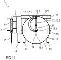
- Figure 11 is a schematic side view of the insertion arrangement 1 with the cam 15.1 of the proximal cross beam 15 having reached the outer end of the linear section 12.2.
- the proximal cross beam 15 is moved into the proximal position and has taken along the proximal prong 7.2 of the needle retainer 7 moving the needle retainer 7 and the needle 2 into the retracted position RP.
- the gap has been closed by the distal prong 7.1 abutting the distal cross beam 16.
- the geometry of the notch 12, in particular the curved section 12.1 may be modified to adapt the process of tensioning the spring 21 to the requirements of the respective application.
- the semi-circular section 12.1 may be replaced by a curved section having a different shape.
- the wheel 10 may be a gearwheel adapted to be driven by a motor.
- drug or “medicament”, as used herein, means a pharmaceutical formulation containing at least one pharmaceutically active compound, wherein in one embodiment the pharmaceutically active compound has a molecular weight up to 1500 Da and/or is a peptide, a proteine, a polysaccharide, a vaccine, a DNA, a RNA, an enzyme, an antibody or a fragment thereof, a hormone or an oligonucleotide, or a mixture of the above-mentioned pharmaceutically active compound, wherein in a further embodiment the pharmaceutically active compound is useful for the treatment and/or prophylaxis of diabetes mellitus or complications associated with diabetes mellitus such as diabetic retinopathy, thromboembolism disorders such as deep vein or pulmonary thromboembolism, acute coronary syndrome (ACS), angina, myocardial infarction, cancer, macular degeneration, inflammation, hay fever, atherosclerosis and/or rheumatoid arthritis, wherein in a further
- Insulin analogues are for example Gly(A21), Arg(B31), Arg(B32) human insulin; Lys(B3), Glu(B29) human insulin; Lys(B28), Pro(B29) human insulin; Asp(B28) human insulin; human insulin, wherein proline in position B28 is replaced by Asp, Lys, Leu, Val or Ala and wherein in position B29 Lys may be replaced by Pro; Ala(B26) human insulin; Des(B28-B30) human insulin; Des(B27) human insulin and Des(B30) human insulin.
- Insulin derivates are for example B29-N-myristoyl-des(B30) human insulin; B29-N-palmitoyl-des(B30) human insulin; B29-N-myristoyl human insulin; B29-N-palmitoyl human insulin; B28-N-myristoyl LysB28ProB29 human insulin; B28-N-palmitoyl-LysB28ProB29 human insulin; B30-N-myristoyl-ThrB29LysB30 human insulin; B30-N-palmitoyl- ThrB29LysB30 human insulin; B29-N-(N-palmitoyl-Y-glutamyl)-des(B30) human insulin; B29-N-(N-lithocholyl-Y-glutamyl)-des(B30) human insulin; B29-N-( ⁇ -carboxyheptadecanoyl)-des(B30) human insulin and B29-N-( ⁇ -carbox
- Exendin-4 for example means Exendin-4(1-39), a peptide of the sequence H-His-Gly-Glu-Gly-Thr-Phe-Thr-Ser-Asp-Leu-Ser-Lys-Gln-Met-Glu-Glu-Glu-Ala-Val-Arg-Leu-Phe-Ile-Glu-Trp-Leu-Lys-Asn-Gly-Gly-Pro-Ser-Ser-Gly-Ala-Pro-Pro-Pro-Ser-NH2.
- Exendin-4 derivatives are for example selected from the following list of compounds:
- Hormones are for example hypophysis hormones or hypothalamus hormones or regulatory active peptides and their antagonists as listed in Rote Liste, ed. 2008, Chapter 50 , such as Gonadotropine (Follitropin, Lutropin, Choriongonadotropin, Menotropin), Somatropine (Somatropin), Desmopressin, Terlipressin, Gonadorelin, Triptorelin, Leuprorelin, Buserelin, Nafarelin, Goserelin.
- Gonadotropine Follitropin, Lutropin, Choriongonadotropin, Menotropin
- Somatropine Somatropin
- Desmopressin Terlipressin
- Gonadorelin Triptorelin
- Leuprorelin Buserelin
- Nafarelin Goserelin.
- a polysaccharide is for example a glucosaminoglycane, a hyaluronic acid, a heparin, a low molecular weight heparin or an ultra low molecular weight heparin or a derivative thereof, or a sulphated, e.g. a poly-sulphated form of the above-mentioned polysaccharides, and/or a pharmaceutically acceptable salt thereof.
- An example of a pharmaceutically acceptable salt of a poly-sulphated low molecular weight heparin is enoxaparin sodium.
- Antibodies are globular plasma proteins (-150 kDa) that are also known as immunoglobulins which share a basic structure. As they have sugar chains added to amino acid residues, they are glycoproteins.
- the basic functional unit of each antibody is an immunoglobulin (Ig) monomer (containing only one Ig unit); secreted antibodies can also be dimeric with two Ig units as with IgA, tetrameric with four Ig units like teleost fish IgM, or pentameric with five Ig units, like mammalian IgM.
- Ig immunoglobulin
- the Ig monomer is a "Y"-shaped molecule that consists of four polypeptide chains; two identical heavy chains and two identical light chains connected by disulfide bonds between cysteine residues. Each heavy chain is about 440 amino acids long; each light chain is about 220 amino acids long. Heavy and light chains each contain intrachain disulfide bonds which stabilize their folding. Each chain is composed of structural domains called Ig domains. These domains contain about 70-110 amino acids and are classified into different categories (for example, variable or V, and constant or C) according to their size and function. They have a characteristic immunoglobulin fold in which two ⁇ sheets create a "sandwich" shape, held together by interactions between conserved cysteines and other charged amino acids.
- Ig heavy chain There are five types of mammalian Ig heavy chain denoted by ⁇ , ⁇ , ⁇ , ⁇ , and ⁇ .
- the type of heavy chain present defines the isotype of antibody; these chains are found in IgA, IgD, IgE, IgG, and IgM antibodies, respectively.
- Distinct heavy chains differ in size and composition; ⁇ and ⁇ contain approximately 450 amino acids and ⁇ approximately 500 amino acids, while ⁇ and ⁇ have approximately 550 amino acids.
- Each heavy chain has two regions, the constant region (C H ) and the variable region (V H ).
- the constant region is essentially identical in all antibodies of the same isotype, but differs in antibodies of different isotypes.
- Heavy chains ⁇ , ⁇ and ⁇ have a constant region composed of three tandem Ig domains, and a hinge region for added flexibility; heavy chains ⁇ and ⁇ have a constant region composed of four immunoglobulin domains.
- the variable region of the heavy chain differs in antibodies produced by different B cells, but is the same for all antibodies produced by a single B cell or B cell clone.
- the variable region of each heavy chain is approximately 110 amino acids long and is composed of a single Ig domain.
- a light chain has two successive domains: one constant domain (CL) and one variable domain (VL).
- CL constant domain
- VL variable domain
- the approximate length of a light chain is 211 to 217 amino acids.
- Each antibody contains two light chains that are always identical; only one type of light chain, ⁇ or ⁇ , is present per antibody in mammals.
- variable (V) regions are responsible for binding to the antigen, i.e. for its antigen specificity.
- VL variable light
- VH variable heavy chain
- CDRs Complementarity Determining Regions
- an "antibody fragment” contains at least one antigen binding fragment as defined above, and exhibits essentially the same function and specificity as the complete antibody of which the fragment is derived from.
- Limited proteolytic digestion with papain cleaves the Ig prototype into three fragments. Two identical amino terminal fragments, each containing one entire L chain and about half an H chain, are the antigen binding fragments (Fab).
- the Fc contains carbohydrates, complement-binding, and FcR-binding sites.
- F(ab')2 is divalent for antigen binding.
- the disulfide bond of F(ab')2 may be cleaved in order to obtain Fab'.
- the variable regions of the heavy and light chains can be fused together to form a single chain variable fragment (scFv).
- Pharmaceutically acceptable salts are for example acid addition salts and basic salts.
- Acid addition salts are e.g. HCI or HBr salts.
- Basic salts are e.g. salts having a cation selected from alkali or alkaline, e.g. Na+, or K+, or Ca2+, or an ammonium ion N+(R1)(R2)(R3)(R4), wherein R1 to R4 independently of each other mean: hydrogen, an optionally substituted C1-C6-alkyl group, an optionally substituted C2-C6-alkenyl group, an optionally substituted C6-C10-aryl group, or an optionally substituted C6-C10-heteroaryl group.
Landscapes
- Health & Medical Sciences (AREA)
- Vascular Medicine (AREA)
- Engineering & Computer Science (AREA)
- Anesthesiology (AREA)
- Biomedical Technology (AREA)
- Heart & Thoracic Surgery (AREA)
- Hematology (AREA)
- Life Sciences & Earth Sciences (AREA)
- Animal Behavior & Ethology (AREA)
- General Health & Medical Sciences (AREA)
- Public Health (AREA)
- Veterinary Medicine (AREA)
- Infusion, Injection, And Reservoir Apparatuses (AREA)
Description
- The invention relates to a needle insertion arrangement comprising a drive mechanism.
- Administering an injection is a process which presents a number of risks and challenges for users and healthcare professionals, both mental and physical. During manual insertion of an injection needle into an injection site, e.g. the skin of a patient, it may be difficult to avoid tilting and bending of the needle and the insertion may be slow thus causing pain.
-
WO 2009/024522 A1 discloses an injection apparatus for making an injection at a predetermined depth in skin comprising: a skin positioning member, an injection needle, and means guiding the injection needle for movement from a parking position above the skin beside said skin positioning member to slide beneath said skin positioning member to an injection position; wherein: the tip of the injection needle is closer to the longitudinal axis of the shaft portion than is the outside of the shaft portion and/or the length of the lumen opening of the needle is in a range from 5 to 15 times the diameter of the shaft of the needle. An injection needle wherein the length of the lumen opening of the needle is in a range from 5 to 15 times the diameter of the shaft of the needle. -
WO 03/072172 A2 - There remains a need for an improved needle insertion arrangement comprising a drive mechanism.
- It is an object of the present invention to provide an improved needle insertion arrangement comprising a drive mechanism
- The object is achieved by a needle insertion arrangement according to
claim 1. - Exemplary embodiments of the invention are given in the dependent claims.
- According to the invention a drive mechanism for a needle insertion arrangement comprises a rotatable wheel with a notch having a closed curve geometry comprising a curved section and a linear section, wherein at least one cross beam is movably arranged and engageable to an injection needle to move it between a retracted position and an extended position, wherein the cross beam comprises a cam adapted to engage the notch.
- In an exemplary embodiment the notch runs from a centre of the wheel towards a perimeter of the wheel and back to the centre.
- In an exemplary embodiment the curved section is arranged as a semi-circular section.
- In an exemplary embodiment the drive mechanism comprises a proximal cross beam and a distal cross beam arranged in parallel, having respective cams and independently movable along at least one linear guide.
- In an exemplary embodiment at an intersection of the curved section with the linear section near the centre of the wheel the notch comprises a bulge adapted to receive both cams.
- In an exemplary embodiment a spring is arranged between the cross beams biasing them apart.
- In an exemplary embodiment the drive mechanism further comprises a needle retainer adapted to retain the injection needle, movable in parallel with the at least one cross beam and adapted to be engaged by the at least one cross beam.
- In an exemplary embodiment the needle retainer comprises a distal prong adapted to be engaged by the distal cross beam and a proximal prong adapted to be engaged by the proximal cross beam, the distal prong and the proximal prong spaced from each other.
- In an exemplary embodiment a distance between the distal prong and the proximal prong corresponds to a length of the linear section of the notch.
In an exemplary embodiment a first linear guide is arranged for guiding movements of the needle retainer.
In an exemplary embodiment a second linear guide and a third linear guide for guiding movements of the cross beams are arranged in parallel with the first linear guide.
In an exemplary embodiment the wheel is arranged between the second linear guide and the third linear guide.
In an exemplary embodiment the wheel comprises a knurl.
According to the invention the drive mechanism is applied in an insertion arrangement for moving an injection needle between a retracted position and an extended position, comprising a disposable unit, comprising a needle base, to which the needle is fixed, and the drive mechanism, wherein the needle retainer is adapted to retain the needle base.
The insertion arrangement has only limited space requirements determined by the required needle insertion depth thus allowing for low profile injection devices with a high wearing comfort. The insertion arrangement achieves high speed needle movements and exact needle guidance thus reducing pain for the patients when semi-automatically inserting and retracting the needle and increasing consumer acceptance and satisfaction. A speed profile of the needle movement may be varied by modifying the geometry of the notch. The insertion arrangement may be embodied with manual or motor powered operation. The low part count of the insertion arrangement and the low allows for an increased mechanical robustness and low manufacturing costs. The insertion arrangement is a fault-tolerant system.
Further scope of applicability of the present invention will become apparent from the detailed description given hereinafter. However, it should be understood that the detailed description and specific examples, while indicating exemplary embodiments of the invention, are given by way of illustration only, since various changes and modifications within the scope of the invention as defined by the appended claims will become apparent to those skilled in the art from this detailed description. - The present invention will become more fully understood from the detailed description given hereinbelow and the accompanying drawings which are given by way of illustration only, and thus, are not limitive of the present invention, and wherein:
- Figure 1
- is a schematic view of an exemplary embodiment of an insertion arrangement for inserting an injection needle into an injection site,
- Figure 2
- is a schematic exploded view of the insertion arrangement,
- Figure 3
- is a schematic side view of the insertion arrangement in an initial position, wherein the needle is in a retracted position and wherein a wheel is in a first angular position,
- Figure 4
- is a schematic side view of the insertion arrangement during rotation of the wheel,
- Figure 5
- is a schematic side view of the insertion arrangement during further rotation of the wheel,
- Figure 6
- is a schematic side view of the insertion arrangement, wherein the wheel has been rotated into a second angular position,
- Figure 7
- is a schematic side view of the insertion arrangement with the needle moved into an extended position,
- Figure 8
- is a schematic view of the insertion arrangement during further rotation of the wheel,
- Figure 9
- is a schematic view of the insertion arrangement during further rotation of the wheel,
- Figure 10
- is a schematic side view of the insertion arrangement with the wheel rotated into the first angular position, and
- Figure 11
- is a schematic side view of the insertion arrangement with the needle moved into the retracted position.
- Corresponding parts are marked with the same reference symbols in all figures.
-
Figure 1 is a schematic view of an exemplary embodiment of aninsertion arrangement 1 for automatically or semi-automatically inserting aninjection needle 2 into an injection site.Figure 2 is a related schematic exploded view. The injection may be performed manually or by a motor. Thearrangement 1 may be applied in medicament pumps, e.g. insulin pumps which may be permanently worn on the body. - The
injection needle 2 is part of a disposable unit 3, further comprising atube 4 for establishing a fluid communication of theneedle 2 with a drug container (not illustrated) and comprising aneedle base 6, to which theinjection needle 2 may be fixed for mechanically connecting theneedle 2 to a drive mechanism 9 of an injection unit (not illustrated). Theneedle base 6 is inserted in a forkedneedle retainer 7 which is arranged to be moved between a retracted position RP and an extended position EP in a firstlinear guide 8. This linear movement corresponds to insertion of theneedle 2 into the injection site, e.g. subcutaneous body tissue and removal from the injection site, respectively. - A drive mechanism 9 for the
needle 2 comprises a wheel 10 with aknurl 11 for facilitating manual operation. Anotch 12 having a closed curve geometry is arranged on one end face 13 of the wheel 10, wherein thenotch 12 runs from acentre 14 of the wheel 10 towards the perimeter and back to thecentre 14. In the illustrated embodiment thenotch 12 comprises a curved section 12.1, e.g. semi-circular, and a linear section 12.2. At an intersection of the curved section 12.1 with the linear section 12.2 near thecentre 14 of the wheel thenotch 12 comprises a bulge 12.3. Furthermore, the drive mechanism 9 comprises aproximal cross beam 15 and adistal cross beam 16 arranged in parallel. Both cross beams 15, 16 are independently movable along a secondlinear guide 17 and a thirdlinear guide 18. The second and thirdlinear guide linear guide 8. Eachcross beam notch 12 in the wheel 10. Aspring 21 is arranged between the cross beams 15, 16 biasing them apart. - If the wheel 10 is rotated, the cams 15.1, 16.1 are guided through the
notch 12, wherein one of the cams 15.1, 16.1 runs through the curved section 12.1 of thenotch 12 and is thus moved towards thecentre 14 of the wheel 10, where the other one of the cams 16.1, 15.1 is located. If the one of the cams 15.1, 16.1 is moved towards thecentre 14 of the wheel 10 therespective cross beam other cross beam spring 21. If the cross beams 15, 16 have reached their minimum distance and thespring 21 is maximally compressed, the linear section 12.2 arrives in a vertical position in parallel with thelinear guides linear guides compressed spring 21 one of the cross beams 15, 16 therefore moves until the related cam 15.1, 16.1 hits the outer end of the linear section 12.2. Which one of the cross beams 15, 16 moves depends on whether the linear section 12.2 points in a distal direction D or in a proximal direction P from thecentre 14. If the linear section 12.2 points in the proximal direction P from thecentre 14, theproximal cross beam 15 moves in the proximal direction P while thedistal cross beam 16 remains in position. If the linear section 12.2 points in the distal direction P from thecentre 14, thedistal cross beam 16 moves in the distal direction D while theproximal cross beam 15 remains in position. - The forked
needle retainer 7 comprises a distal prong 7.1 adapted to be engaged by thedistal cross beam 16 and a proximal prong 7.2 adapted to be engaged by theproximal cross beam 15. A distance between the distal prong 7.1 and the proximal prong 7.2 corresponds to the length of the linear section 12.2 of thenotch 12. Thus, theneedle retainer 7 and theneedle 2 remain in position if one of the cross beams 15, 16 is moved towards the other compressing thespring 21. As the linear section 12.2 arrives in a vertical position in parallel with thelinear guides spring 21 relaxes forwarding the other one of the cross beams 15, 16 thus moving theneedle 2 from the retracted position RP to the extended position EP or vice versa with high speed. A detent (not illustrated) may be arranged for preventing theneedle retainer 7 from moving out of the retracted position RP or the extended position EP by gravity or inertial forces. - A sequence of operation of the
insertion arrangement 1 is as follows: -
Figure 3 is a schematic side view of theinsertion arrangement 1 in an initial position. The disposable unit 3 with theneedle base 6, theneedle 2 and thetube 4 has been inserted in the forkedneedle retainer 7. The wheel 10 is in a first angular position AP1 in which the linear section 12.2 of thenotch 12 is in a vertical position in parallel with thelinear guides centre 14. Theproximal cross beam 15 is in a proximal position with its cam 15.1 located at the outer end of the linear section 12.2 and abuts the proximal prong 7.2 of theneedle retainer 7. Thedistal cross beam 16 is in a central position with its cam 16.1 located at the inner end of the linear section 12.2 in the bulge 12.3 and abuts the distal prong 7.2 of theneedle retainer 7. Due to the positions of the cross beams 15, 16 theneedle retainer 7 and theneedle 2 are in the retracted position RP. -
Figure 4 is a schematic side view of theinsertion arrangement 1 during rotation of the wheel 10. The wheel 10 is rotated clockwise by about 45° with respect to the first angular position AP1. - The cam 15.1 of the
proximal cross beam 15 slides along the curved section 12.1 of thenotch 12 moving theproximal cross beam 15 in the distal direction D and compressing thespring 21. Theproximal cross beam 15 is thus removed from the proximal prong 7.2 of theneedle retainer 7. Thedistal cross beam 16 remains in the central position. Due to the movement of the proximal cross beam 15 a gap is created between theproximal cross beam 15 and the proximal prong 7.2 of theneedle retainer 7. Theneedle retainer 7 and theneedle 2 remain in the retracted position RP. -
Figure 5 is a schematic side view of theinsertion arrangement 1 during further rotation of the wheel 10. The wheel 10 is rotated clockwise by about 160° with respect to the first angular position AP1. The cam 15.1 of theproximal cross beam 15 still slides along the curved section 12.1 of thenotch 12 moving theproximal cross beam 15 further in the distal direction D and compressing thespring 21. As theproximal cross beam 15 approaches the central position it slows down due to the position of the cam 15.1 in the curved section 12.1 until the cam 15.1 enters the bulge 12.3, which is wide enough for both cams 15.1, 16.1 at a time. At the same time thespring 21 is almost maximally compressed. Thedistal cross beam 16 remains in the central position. The gap between theproximal cross beam 15 and the proximal prong 7.2 of theneedle retainer 7 has almost reached its maximum width. Theneedle retainer 7 and theneedle 2 remain in the retracted position RP. -
Figure 6 is a schematic side view of theinsertion arrangement 1 during further rotation of the wheel 10. The wheel 10 is rotated clockwise by about 180° with respect to the first angular position AP1 and thus reaches a second angular position AP2, in which the linear section 12.2 of thenotch 12 is in a vertical position in parallel with thelinear guides centre 14. This releases the cam 16.1 of thedistal cross beam 16 allowing thespring 21 to move thedistal cross beam 16 in the distal direction D. This movement is performed with relatively high speed depending on the force of thecompressed spring 21. The cam 15.1 of theproximal cross beam 15 is retained in the bulge 12.3 thus keeping theproximal cross beam 15 in the central position. As thedistal cross beam 16 moves it takes theneedle retainer 7 with it moving it in the distal direction D and reducing the width of the gap between theproximal cross beam 15 and the proximal prong 7.2 of theneedle retainer 7. -
Figure 7 is a schematic side view of theinsertion arrangement 1 with the cam 16.1 of thedistal cross beam 16 having reached the outer end of the linear section 12.2. Thedistal cross beam 16 is moved into a distal position and has taken along the distal prong 7.1 of theneedle retainer 7 moving theneedle retainer 7 and theneedle 2 into the extended position EP in order to rapidly insert theneedle 2 into an injection site, e.g. subcutaneous body tissue. The gap has been closed by the proximal prong 7.2 abutting theproximal cross beam 15. -
Figure 8 is a schematic view of theinsertion arrangement 1 during further rotation of the wheel 10. The wheel 10 is rotated clockwise by about 45° with respect to the second angular position AP2. The cam 16.1 of thedistal cross beam 16 slides along the curved section 12.1 of thenotch 12 moving thedistal cross beam 16 in the proximal direction P and compressing thespring 21. Thedistal cross beam 16 is thus removed from the distal prong 7.1 of theneedle retainer 7. Theproximal cross beam 15 remains in the central position. Due to the movement of the distal cross beam 16 a gap is created between thedistal cross beam 16 and the distal prong 7.1 of theneedle retainer 7. Theneedle retainer 7 and theneedle 2 remain in the extended position EP. -
Figure 9 is a schematic view of theinsertion arrangement 1 during further rotation of the wheel 10. The wheel 10 is rotated clockwise by about 115° with respect to the second angular position AP2. The cam 16.1 of thedistal cross beam 16 still slides along the curved section 12.1 of thenotch 12 moving thedistal cross beam 16 further in the proximal direction P and compressing thespring 21. As thedistal cross beam 16 approaches the central position it slows down due to the position of the cam 16.1 in the curved section 12.1 until the cam 16.1 enters the bulge 12.3. At the same time thespring 21 is almost maximally compressed. Theproximal cross beam 15 remains in the central position. The gap between thedistal cross beam 16 and the distal prong 7.1 of theneedle retainer 7 has almost reached its maximum width. Theneedle retainer 7 and theneedle 2 remain in the extended position EP. -
Figure 10 is a schematic side view of theinsertion arrangement 1 during further rotation of the wheel 10. The wheel 10 is rotated clockwise by about 180° with respect to the second angular position AP2 and thus reaches the first angular position AP1, in which the linear section 12.2 of thenotch 12 is in a vertical position in parallel with thelinear guides centre 14. This releases the cam 15.1 of theproximal cross beam 15 allowing thespring 21 to move theproximal cross beam 15 in the proximal direction P. This movement is performed with relatively high speed depending on the force of thecompressed spring 21. The cam 16.1 of thedistal cross beam 16 is retained in the bulge 12.3 thus keeping thedistal cross beam 16 in the central position. As theproximal cross beam 15 moves it takes theneedle retainer 7 with it moving it in the proximal direction P and reducing the width of the gap between thedistal cross beam 16 and the distal prong 7.1 of theneedle retainer 7. -
Figure 11 is a schematic side view of theinsertion arrangement 1 with the cam 15.1 of theproximal cross beam 15 having reached the outer end of the linear section 12.2. Theproximal cross beam 15 is moved into the proximal position and has taken along the proximal prong 7.2 of theneedle retainer 7 moving theneedle retainer 7 and theneedle 2 into the retracted position RP. The gap has been closed by the distal prong 7.1 abutting thedistal cross beam 16. - In an alternative embodiment the geometry of the
notch 12, in particular the curved section 12.1 may be modified to adapt the process of tensioning thespring 21 to the requirements of the respective application. For this purpose the semi-circular section 12.1 may be replaced by a curved section having a different shape. - In an alternative embodiment the wheel 10 may be a gearwheel adapted to be driven by a motor.
- The term "drug" or "medicament", as used herein, means a pharmaceutical formulation containing at least one pharmaceutically active compound,
wherein in one embodiment the pharmaceutically active compound has a molecular weight up to 1500 Da and/or is a peptide, a proteine, a polysaccharide, a vaccine, a DNA, a RNA, an enzyme, an antibody or a fragment thereof, a hormone or an oligonucleotide, or a mixture of the above-mentioned pharmaceutically active compound,
wherein in a further embodiment the pharmaceutically active compound is useful for the treatment and/or prophylaxis of diabetes mellitus or complications associated with diabetes mellitus such as diabetic retinopathy, thromboembolism disorders such as deep vein or pulmonary thromboembolism, acute coronary syndrome (ACS), angina, myocardial infarction, cancer, macular degeneration, inflammation, hay fever, atherosclerosis and/or rheumatoid arthritis,
wherein in a further embodiment the pharmaceutically active compound comprises at least one peptide for the treatment and/or prophylaxis of diabetes mellitus or complications associated with diabetes mellitus such as diabetic retinopathy,
wherein in a further embodiment the pharmaceutically active compound comprises at least one human insulin or a human insulin analogue or derivative, glucagon-like peptide (GLP-1) or an analogue or derivative thereof, or exendin-3 or exendin-4 or an analogue or derivative of exendin-3 or exendin-4. - Insulin analogues are for example Gly(A21), Arg(B31), Arg(B32) human insulin; Lys(B3), Glu(B29) human insulin; Lys(B28), Pro(B29) human insulin; Asp(B28) human insulin; human insulin, wherein proline in position B28 is replaced by Asp, Lys, Leu, Val or Ala and wherein in position B29 Lys may be replaced by Pro; Ala(B26) human insulin; Des(B28-B30) human insulin; Des(B27) human insulin and Des(B30) human insulin.
- Insulin derivates are for example B29-N-myristoyl-des(B30) human insulin; B29-N-palmitoyl-des(B30) human insulin; B29-N-myristoyl human insulin; B29-N-palmitoyl human insulin; B28-N-myristoyl LysB28ProB29 human insulin; B28-N-palmitoyl-LysB28ProB29 human insulin; B30-N-myristoyl-ThrB29LysB30 human insulin; B30-N-palmitoyl- ThrB29LysB30 human insulin; B29-N-(N-palmitoyl-Y-glutamyl)-des(B30) human insulin; B29-N-(N-lithocholyl-Y-glutamyl)-des(B30) human insulin; B29-N-(ω-carboxyheptadecanoyl)-des(B30) human insulin and B29-N-(ω-carboxyheptadecanoyl) human insulin.
- Exendin-4 for example means Exendin-4(1-39), a peptide of the sequence H-His-Gly-Glu-Gly-Thr-Phe-Thr-Ser-Asp-Leu-Ser-Lys-Gln-Met-Glu-Glu-Glu-Ala-Val-Arg-Leu-Phe-Ile-Glu-Trp-Leu-Lys-Asn-Gly-Gly-Pro-Ser-Ser-Gly-Ala-Pro-Pro-Pro-Ser-NH2.
- Exendin-4 derivatives are for example selected from the following list of compounds:
- H-(Lys)4-des Pro36, des Pro37 Exendin-4(1-39)-NH2,
- H-(Lys)5-des Pro36, des Pro37 Exendin-4(1-39)-NH2,
- des Pro36 Exendin-4(1-39),
- des Pro36 [Asp28] Exendin-4(1-39),
- des Pro36 [IsoAsp28] Exendin-4(1-39),
- des Pro36 [Met(O)14, Asp28] Exendin-4(1-39),
- des Pro36 [Met(O)14, IsoAsp28] Exendin-4(1-39),
- des Pro36 [Trp(O2)25, Asp28] Exendin-4(1-39),
- des Pro36 [Trp(O2)25, IsoAsp28] Exendin-4(1-39),
- des Pro36 [Met(O)14 Trp(O2)25, Asp28] Exendin-4(1-39),
- des Pro36 [Met(O)14 Trp(O2)25, IsoAsp28] Exendin-4(1-39); or
- des Pro36 [Asp28] Exendin-4(1-39),
- des Pro36 [IsoAsp28] Exendin-4(1-39),
- des Pro36 [Met(O)14, Asp28] Exendin-4(1-39),
- des Pro36 [Met(O)14, IsoAsp28] Exendin-4(1-39),
- des Pro36 [Trp(O2)25, Asp28] Exendin-4(1-39),
- des Pro36 [Trp(O2)25, IsoAsp28] Exendin-4(1-39),
- des Pro36 [Met(O)14 Trp(O2)25, Asp28] Exendin-4(1-39),
- des Pro36 [Met(O)14 Trp(O2)25, IsoAsp28] Exendin-4(1-39),
- wherein the group -Lys6-NH2 may be bound to the C-terminus of the Exendin-4 derivative;
- or an Exendin-4 derivative of the sequence
- des Pro36 Exendin-4(1-39)-Lys6-NH2 (AVE0010),
- H-(Lys)6-des Pro36 [Asp28] Exendin-4(1-39)-Lys6-NH2,
- des Asp28 Pro36, Pro37, Pro38Exendin-4(1-39)-NH2,
- H-(Lys)6-des Pro36, Pro38 [Asp28] Exendin-4(1-39)-NH2,
- H-Asn-(Glu)5des Pro36, Pro37, Pro38 [Asp28] Exendin-4(1-39)-NH2,
- des Pro36, Pro37, Pro38 [Asp28] Exendin-4(1-39)-(Lys)6-NH2,
- H-(Lys)6-des Pro36, Pro37, Pro38 [Asp28] Exendin-4(1-39)-(Lys)6-NH2,
- H-Asn-(Glu)5-des Pro36, Pro37, Pro38 [Asp28] Exendin-4(1-39)-(Lys)6-NH2,
- H-(Lys)6-des Pro36 [Trp(O2)25, Asp28] Exendin-4(1-39)-Lys6-NH2,
- H-des Asp28 Pro36, Pro37, Pro38 [Trp(O2)25] Exendin-4(1-39)-NH2,
- H-(Lys)6-des Pro36, Pro37, Pro38 [Trp(O2)25, Asp28] Exendin-4(1-39)-NH2,
- H-Asn-(Glu)5-des Pro36, Pro37, Pro38 [Trp(O2)25, Asp28] Exendin-4(1-39)-NH2,
- des Pro36, Pro37, Pro38 [Trp(O2)25, Asp28] Exendin-4(1-39)-(Lys)6-NH2,
- H-(Lys)6-des Pro36, Pro37, Pro38 [Trp(O2)25, Asp28] Exendin-4(1-39)-(Lys)6-NH2,
- H-Asn-(Glu)5-des Pro36, Pro37, Pro38 [Trp(O2)25, Asp28] Exendin-4(1-39)-(Lys)6-NH2,
- H-(Lys)6-des Pro36 [Met(O)14, Asp28] Exendin-4(1-39)-Lys6-NH2,
- des Met(O)14 Asp28 Pro36, Pro37, Pro38 Exendin-4(1-39)-NH2,
- H-(Lys)6-desPro36, Pro37, Pro38 [Met(O)14, Asp28] Exendin-4(1-39)-NH2,
- H-Asn-(Glu)5-des Pro36, Pro37, Pro38 [Met(O)14, Asp28] Exendin-4(1-39)-NH2,
- des Pro36, Pro37, Pro38 [Met(O)14, Asp28] Exendin-4(1-39)-(Lys)6-NH2,
- H-(Lys)6-des Pro36, Pro37, Pro38 [Met(O)14, Asp28] Exendin-4(1-39)-(Lys)6-NH2,
- H-Asn-(Glu)5 des Pro36, Pro37, Pro38 [Met(O)14, Asp28] Exendin-4(1-39)-(Lys)6-NH2,
- H-Lys6-des Pro36 [Met(O)14, Trp(O2)25, Asp28] Exendin-4(1-39)-Lys6-NH2,
- H-des Asp28 Pro36, Pro37, Pro38 [Met(O)14, Trp(O2)25] Exendin-4(1-39)-NH2,
- H-(Lys)6-des Pro36, Pro37, Pro38 [Met(O)14, Asp28] Exendin-4(1-39)-NH2,
- H-Asn-(Glu)5-des Pro36, Pro37, Pro38 [Met(O)14, Trp(O2)25, Asp28] Exendin-4(1-39)-NH2,
- des Pro36, Pro37, Pro38 [Met(O)14, Trp(O2)25, Asp28] Exendin-4(1-39)-(Lys)6-NH2,
- H-(Lys)6-des Pro36, Pro37, Pro38 [Met(O)14, Trp(O2)25, Asp28] Exendin-4(S1-39)-(Lys)6-NH2,
- H-Asn-(Glu)5-des Pro36, Pro37, Pro38 [Met(O)14, Trp(O2)25, Asp28] Exendin-4(1-39)-(Lys)6-NH2;
- or a pharmaceutically acceptable salt or solvate of any one of the afore-mentioned Exendin-4 derivative.
- Hormones are for example hypophysis hormones or hypothalamus hormones or regulatory active peptides and their antagonists as listed in Rote Liste, ed. 2008, Chapter 50, such as Gonadotropine (Follitropin, Lutropin, Choriongonadotropin, Menotropin), Somatropine (Somatropin), Desmopressin, Terlipressin, Gonadorelin, Triptorelin, Leuprorelin, Buserelin, Nafarelin, Goserelin.
- A polysaccharide is for example a glucosaminoglycane, a hyaluronic acid, a heparin, a low molecular weight heparin or an ultra low molecular weight heparin or a derivative thereof, or a sulphated, e.g. a poly-sulphated form of the above-mentioned polysaccharides, and/or a pharmaceutically acceptable salt thereof. An example of a pharmaceutically acceptable salt of a poly-sulphated low molecular weight heparin is enoxaparin sodium.
- Antibodies are globular plasma proteins (-150 kDa) that are also known as immunoglobulins which share a basic structure. As they have sugar chains added to amino acid residues, they are glycoproteins. The basic functional unit of each antibody is an immunoglobulin (Ig) monomer (containing only one Ig unit); secreted antibodies can also be dimeric with two Ig units as with IgA, tetrameric with four Ig units like teleost fish IgM, or pentameric with five Ig units, like mammalian IgM.
- The Ig monomer is a "Y"-shaped molecule that consists of four polypeptide chains; two identical heavy chains and two identical light chains connected by disulfide bonds between cysteine residues. Each heavy chain is about 440 amino acids long; each light chain is about 220 amino acids long. Heavy and light chains each contain intrachain disulfide bonds which stabilize their folding. Each chain is composed of structural domains called Ig domains. These domains contain about 70-110 amino acids and are classified into different categories (for example, variable or V, and constant or C) according to their size and function. They have a characteristic immunoglobulin fold in which two β sheets create a "sandwich" shape, held together by interactions between conserved cysteines and other charged amino acids.
- There are five types of mammalian Ig heavy chain denoted by α, δ, ε, γ, and µ. The type of heavy chain present defines the isotype of antibody; these chains are found in IgA, IgD, IgE, IgG, and IgM antibodies, respectively.
- Distinct heavy chains differ in size and composition; α and γ contain approximately 450 amino acids and δ approximately 500 amino acids, while µ and ε have approximately 550 amino acids. Each heavy chain has two regions, the constant region (CH) and the variable region (VH). In one species, the constant region is essentially identical in all antibodies of the same isotype, but differs in antibodies of different isotypes. Heavy chains γ, α and δ have a constant region composed of three tandem Ig domains, and a hinge region for added flexibility; heavy chains µ and ε have a constant region composed of four immunoglobulin domains. The variable region of the heavy chain differs in antibodies produced by different B cells, but is the same for all antibodies produced by a single B cell or B cell clone. The variable region of each heavy chain is approximately 110 amino acids long and is composed of a single Ig domain.
- In mammals, there are two types of immunoglobulin light chain denoted by λ and κ. A light chain has two successive domains: one constant domain (CL) and one variable domain (VL). The approximate length of a light chain is 211 to 217 amino acids. Each antibody contains two light chains that are always identical; only one type of light chain, κ or λ, is present per antibody in mammals.
- Although the general structure of all antibodies is very similar, the unique property of a given antibody is determined by the variable (V) regions, as detailed above. More specifically, variable loops, three each the light (VL) and three on the heavy (VH) chain, are responsible for binding to the antigen, i.e. for its antigen specificity. These loops are referred to as the Complementarity Determining Regions (CDRs). Because CDRs from both VH and VL domains contribute to the antigen-binding site, it is the combination of the heavy and the light chains, and not either alone, that determines the final antigen specificity.
- An "antibody fragment" contains at least one antigen binding fragment as defined above, and exhibits essentially the same function and specificity as the complete antibody of which the fragment is derived from. Limited proteolytic digestion with papain cleaves the Ig prototype into three fragments. Two identical amino terminal fragments, each containing one entire L chain and about half an H chain, are the antigen binding fragments (Fab). The third fragment, similar in size but containing the carboxyl terminal half of both heavy chains with their interchain disulfide bond, is the crystalizable fragment (Fc). The Fc contains carbohydrates, complement-binding, and FcR-binding sites. Limited pepsin digestion yields a single F(ab')2 fragment containing both Fab pieces and the hinge region, including the H-H interchain disulfide bond. F(ab')2 is divalent for antigen binding. The disulfide bond of F(ab')2 may be cleaved in order to obtain Fab'. Moreover, the variable regions of the heavy and light chains can be fused together to form a single chain variable fragment (scFv).
- Pharmaceutically acceptable salts are for example acid addition salts and basic salts. Acid addition salts are e.g. HCI or HBr salts. Basic salts are e.g. salts having a cation selected from alkali or alkaline, e.g. Na+, or K+, or Ca2+, or an ammonium ion N+(R1)(R2)(R3)(R4), wherein R1 to R4 independently of each other mean: hydrogen, an optionally substituted C1-C6-alkyl group, an optionally substituted C2-C6-alkenyl group, an optionally substituted C6-C10-aryl group, or an optionally substituted C6-C10-heteroaryl group. Further examples of pharmaceutically acceptable salts are described in "Remington's Pharmaceutical Sciences" 17. ed. Alfonso R. Gennaro (Ed.), Mark Publishing Company, Easton, Pa., U.S.A., 1985 and in Encyclopedia of Pharmaceutical Technology.
Pharmaceutically acceptable solvates are for example hydrates.
Those of skill in the art will understand that modifications (additions and/or removals) of various components of the apparatuses, methods and/or systems and embodiments described herein may be made without departing from the full scope of the present invention as defined by the appended claims. -
- 1
- insertion arrangement
- 2
- needle
- 3
- disposable unit
- 4
- tube
- 6
- needle base
- 7
- needle retainer
- 7.1
- distal prong
- 7.2
- proximal prong
- 8
- first linear guide
- 9
- drive mechanism
- 10
- wheel
- 11
- knurl
- 12
- notch
- 12.1
- curved section
- 12.2
- linear section
- 12.3
- bulge
- 13
- end face
- 14
- centre
- 15
- proximal cross beam
- 15.1
- cam
- 16
- distal cross beam
- 16.1
- cam
- 17
- second linear guide
- 18
- third linear guide
- 21
- spring
- AP1
- first angular position
- AP2
- second angular position
- D
- distal direction
- EP
- extended position
- P
- proximal direction
- RP
- retracted position
Claims (13)
- Needle insertion arrangement (1) of an injection device for moving an injection needle (2) between a retracted position (RP) and an extended position (EP), comprising a disposable unit (3), comprising a needle base (6), to which the injection needle (2) is fixed, and a drive mechanism (9), wherein a needle retainer (7) is adapted to retain the needle base (6), the drive mechanism (9) comprising a rotatable wheel (10) with a notch (12), wherein at least one cross beam (15, 16) is movably arranged and engageable to an injection needle (2) to move it between a retracted position (RP) and an extended position (EP), wherein the cross beam (15, 16) comprises a cam (15.1, 16.1) adapted to engage the notch (12) characterized in that the notch (12) has a closed curve geometry comprising a curved section (12.1) and a linear section (12.2).
- Needle insertion arrangement (1) according to claim 1, wherein the notch (12) runs from a centre (14) of the wheel (10) towards a perimeter of the wheel and back to the centre (14).
- Needle insertion arrangement (1) according to one of the claims 1 or 2, wherein the curved section (12.1) is arranged as a semi-circular section.
- Needle insertion arrangement (1) according to one of the preceding claims, comprising a proximal cross beam (15) and a distal cross beam (16) arranged in parallel, having respective cams (15.1, 16.1) and independently movable along at least one linear guide (17, 18).
- Needle insertion arrangement (1) according to claim 4, wherein at an intersection of the curved section (12.1) with the linear section (12.2) near the centre (14) of the wheel (10) the notch (12) comprises a bulge (12.3) adapted to receive both cams (15.1, 16.1).
- Needle insertion arrangement (1) according to one of the claims 4 or 5, wherein a spring (21) is arranged between the cross beams (15, 16) biasing them apart.
- Needle insertion arrangement (1) according to one of the preceding claims, further comprising a needle retainer (7) adapted to retain the injection needle (2), movable in parallel with the at least one cross beam (15, 16) and adapted to be engaged by the at least one cross beam (15, 16).
- Needle insertion arrangement (1) according to claim 7, wherein the needle retainer (7) comprises a distal prong (7.1) adapted to be engaged by the distal cross beam (16) and a proximal prong (7.2) adapted to be engaged by the proximal cross beam (15), the distal prong (7.1) and the proximal prong (7.2) spaced from each other.
- Needle insertion arrangement (1) according to claim 8, wherein a distance between the distal prong (7.1) and the proximal prong (7.2) corresponds to a length of the linear section (12.2) of the notch (12).
- Needle insertion arrangement (1) according to one of the claims 7 to 9, wherein a first linear guide (8) is arranged for guiding movements of the needle retainer (7).
- Needle insertion arrangement (1) according to one of the claims 4 to 10, wherein a second linear guide (17) and a third linear guide (18) for guiding movements of the cross beams (15, 16) are arranged in parallel with the first linear guide (8).
- Needle insertion arrangement (1) according to claim 11, wherein the wheel (10) is arranged between the second linear guide (17) and the third linear guide (18).
- Needle insertion arrangement (1) according to one of the preceding claims, wherein the wheel (10) comprises a knurl.
Priority Applications (1)
| Application Number | Priority Date | Filing Date | Title |
|---|---|---|---|
| EP14758552.5A EP3041548B1 (en) | 2013-09-05 | 2014-09-02 | Drive mechanism for a needle insertion arrangement |
Applications Claiming Priority (3)
| Application Number | Priority Date | Filing Date | Title |
|---|---|---|---|
| EP13183152 | 2013-09-05 | ||
| PCT/EP2014/068597 WO2015032743A1 (en) | 2013-09-05 | 2014-09-02 | Drive mechanism for a needle insertion arrangement |
| EP14758552.5A EP3041548B1 (en) | 2013-09-05 | 2014-09-02 | Drive mechanism for a needle insertion arrangement |
Publications (2)
| Publication Number | Publication Date |
|---|---|
| EP3041548A1 EP3041548A1 (en) | 2016-07-13 |
| EP3041548B1 true EP3041548B1 (en) | 2018-12-19 |
Family
ID=49118365
Family Applications (1)
| Application Number | Title | Priority Date | Filing Date |
|---|---|---|---|
| EP14758552.5A Active EP3041548B1 (en) | 2013-09-05 | 2014-09-02 | Drive mechanism for a needle insertion arrangement |
Country Status (8)
| Country | Link |
|---|---|
| US (1) | US10369278B2 (en) |
| EP (1) | EP3041548B1 (en) |
| JP (1) | JP6434521B2 (en) |
| CN (1) | CN105658267B (en) |
| DK (1) | DK3041548T3 (en) |
| HK (1) | HK1223578A1 (en) |
| TR (1) | TR201902956T4 (en) |
| WO (1) | WO2015032743A1 (en) |
Cited By (1)
| Publication number | Priority date | Publication date | Assignee | Title |
|---|---|---|---|---|
| WO2020178444A1 (en) * | 2019-03-07 | 2020-09-10 | Nemera La Verpilliere | Device for inserting a needle for dispensing a product into a site |
Families Citing this family (11)
| Publication number | Priority date | Publication date | Assignee | Title |
|---|---|---|---|---|
| EP2832390A1 (en) | 2013-07-30 | 2015-02-04 | Sensile Pat AG | Drug delivery device with needle actuation mechanism |
| DK3041527T3 (en) * | 2013-09-05 | 2018-08-13 | Sanofi Aventis Deutschland | DRIVING DEVICE MECHANISM INSTALLATION DEVICE |
| MX2017011603A (en) | 2015-03-10 | 2018-04-24 | Regeneron Pharma | Aseptic piercing system and method. |
| WO2018060027A1 (en) * | 2016-09-27 | 2018-04-05 | Sanofi-Aventis Deutschland Gmbh | A medicament delivery device |
| IL294491B2 (en) | 2017-05-05 | 2024-04-01 | Regeneron Pharma | Auto-injector |
| EP3574941A1 (en) * | 2018-05-28 | 2019-12-04 | Sensile Medical AG | Drug delivery device with needle actuation mechanism |
| EP3852840A1 (en) * | 2018-09-22 | 2021-07-28 | SHL Medical AG | Injector needle insertion retraction assembly |
| EP3893965A4 (en) * | 2018-12-15 | 2022-08-31 | Biolark, Inc. | Kinkless infusion set for medical use |
| US11896801B2 (en) | 2018-12-15 | 2024-02-13 | Mark H Scott | Kinkless infusion set for medical use |
| FR3093437B1 (en) * | 2019-03-07 | 2024-05-24 | Nemera La Verpilliere | Device for inserting a needle for dispensing a product in a site |
| USD1007676S1 (en) | 2021-11-16 | 2023-12-12 | Regeneron Pharmaceuticals, Inc. | Wearable autoinjector |
Family Cites Families (43)
| Publication number | Priority date | Publication date | Assignee | Title |
|---|---|---|---|---|
| GB813439A (en) * | 1956-06-04 | 1959-05-13 | Crabtree & Son Ltd D | An improved method of and apparatus for making tufted carpets |
| US3521676A (en) * | 1968-02-15 | 1970-07-28 | Fieldcrest Mills Inc | Gripper loom for weaving pile fabrics and method |
| US3450081A (en) * | 1968-03-05 | 1969-06-17 | Jacob Rabinow | Safety needle device for sewing machine |
| JPS5576949U (en) * | 1978-11-21 | 1980-05-27 | ||
| JPS5576949A (en) | 1978-12-06 | 1980-06-10 | Showa Denko Kk | Acidic substance analyser by means of high speed liquid chromatograph |
| JPS60117641A (en) | 1983-11-30 | 1985-06-25 | Fujitsu Ltd | Manufacture of semionductor device |
| US4658744A (en) * | 1985-02-28 | 1987-04-21 | Happy Mishin Seizou Kabushiki Kaisha | Cam-using electronic control sewing machine |
| JPS6225358U (en) * | 1985-07-30 | 1987-02-16 | ||
| US5738004A (en) * | 1996-09-26 | 1998-04-14 | Townsend; Ray T. | Means for injecting fluid into a meat product |
| DE19709604A1 (en) * | 1997-03-08 | 1998-09-10 | Claas Usines France | Method and device for fine adjustment of motion sequences on big balers |
| US6530900B1 (en) * | 1997-05-06 | 2003-03-11 | Elan Pharma International Limited | Drug delivery device |
| JP3599535B2 (en) * | 1997-08-04 | 2004-12-08 | 株式会社トスカ | Method and apparatus for connecting filamentous connection body |
| GB0204640D0 (en) * | 2002-02-27 | 2002-04-10 | Torsana Diabetes Diagnostics A | Injection apparatus |
| DE10255133B3 (en) * | 2002-11-26 | 2004-04-08 | Disetronic Licensing Ag | Apparatus for inserting needle unit, especially infusion head, into tissue comprises casing, to which a swiveling arm is attached which has mounting for unit at one end and can be lowered by release button on casing |
| ATE376435T1 (en) * | 2003-06-12 | 2007-11-15 | Disetronic Licensing Ag | INSERTION DEVICE FOR INFUSION SETS |
| EP1502613A1 (en) * | 2003-08-01 | 2005-02-02 | Novo Nordisk A/S | Needle device with retraction means |
| EP1698279A1 (en) * | 2005-03-04 | 2006-09-06 | Disetronic Licensing AG | Sequential insertion of main-penetrators |
| WO2006108809A1 (en) * | 2005-04-13 | 2006-10-19 | Novo Nordisk A/S | Medical skin mountable device and system |
| US7699833B2 (en) * | 2005-05-06 | 2010-04-20 | Moberg Sheldon B | Pump assembly and method for infusion device |
| US8277415B2 (en) * | 2006-08-23 | 2012-10-02 | Medtronic Minimed, Inc. | Infusion medium delivery device and method with drive device for driving plunger in reservoir |
| CA2613111C (en) * | 2005-06-27 | 2015-05-26 | 3M Innovative Properties Company | Microneedle array applicator device and method of array application |
| ATE500860T1 (en) * | 2005-09-15 | 2011-03-15 | Hoffmann La Roche | SYSTEM COMPRISING INSERTION HEAD AND INSERTER |
| DE502005009907D1 (en) * | 2005-09-15 | 2010-08-26 | Roche Diagnostics Gmbh | Insertion head with handle |
| CN2892112Y (en) * | 2006-04-13 | 2007-04-25 | 汤光化 | Slidewheel type venostasis needle |
| US7682338B2 (en) * | 2006-08-23 | 2010-03-23 | Medtronic Minimed, Inc. | Infusion medium delivery system, device and method with needle inserter and needle inserter device and method |
| ES2690306T3 (en) * | 2006-11-28 | 2018-11-20 | F. Hoffmann-La Roche Ag | An insertion device and method to insert an insert subcutaneously into a body |
| CA2677667A1 (en) * | 2007-02-09 | 2008-08-14 | Deka Products Limited Partnership | Automated insertion assembly |
| US8002752B2 (en) | 2007-06-25 | 2011-08-23 | Medingo, Ltd. | Protector apparatus |
| GB0716159D0 (en) * | 2007-08-17 | 2007-09-26 | Precisense As | Injection apparatus |
| CA2715667A1 (en) * | 2008-02-20 | 2009-08-27 | Unomedical A/S | Insertion device with horizontally moving part |
| WO2010072005A1 (en) * | 2008-12-24 | 2010-07-01 | Calasso, Irio, Giuseppe | System and methods for medicament infusion |
| DE202009003050U1 (en) * | 2009-03-06 | 2010-08-12 | Dr. Fritz Faulhaber Gmbh & Co. Kg | Needle puncture device for medical devices |
| US8882710B2 (en) * | 2009-09-02 | 2014-11-11 | Medtronic Minimed, Inc. | Insertion device systems and methods |
| US8998840B2 (en) * | 2009-12-30 | 2015-04-07 | Medtronic Minimed, Inc. | Connection and alignment systems and methods |
| SG10202001055YA (en) * | 2010-05-20 | 2020-04-29 | Becton Dickinson Co | Drug delivery device |
| EP2460553A1 (en) * | 2010-12-02 | 2012-06-06 | Debiotech S.A. | Device for inserting needles |
| EP2836253B1 (en) * | 2012-04-10 | 2019-07-03 | SHL Medical AG | Infusion device |
| MX352018B (en) * | 2012-04-13 | 2017-11-06 | Becton Dickinson Co | Microinfuser with automatic needle retraction. |
| US9114216B2 (en) * | 2012-07-16 | 2015-08-25 | Accunit, Llc | Handheld medical substance dispensing system, apparatus and methods |
| JP6023816B2 (en) * | 2012-09-28 | 2016-11-09 | テルモ株式会社 | Puncture device and drug solution administration device |
| US9913970B2 (en) * | 2012-12-21 | 2018-03-13 | Hisamitsu Pharmaceutical Co., Ltd. | Applicator |
| EP2832390A1 (en) * | 2013-07-30 | 2015-02-04 | Sensile Pat AG | Drug delivery device with needle actuation mechanism |
| US10195342B2 (en) * | 2014-04-24 | 2019-02-05 | Becton, Dickinson And Company | Cannula deployment mechanism |
-
2014
- 2014-09-02 DK DK14758552.5T patent/DK3041548T3/en active
- 2014-09-02 TR TR2019/02956T patent/TR201902956T4/en unknown
- 2014-09-02 US US14/916,667 patent/US10369278B2/en not_active Expired - Fee Related
- 2014-09-02 CN CN201480056152.1A patent/CN105658267B/en not_active Expired - Fee Related
- 2014-09-02 JP JP2016539499A patent/JP6434521B2/en not_active Expired - Fee Related
- 2014-09-02 EP EP14758552.5A patent/EP3041548B1/en active Active
- 2014-09-02 WO PCT/EP2014/068597 patent/WO2015032743A1/en active Application Filing
-
2016
- 2016-10-14 HK HK16111866.0A patent/HK1223578A1/en not_active IP Right Cessation
Non-Patent Citations (1)
| Title |
|---|
| None * |
Cited By (2)
| Publication number | Priority date | Publication date | Assignee | Title |
|---|---|---|---|---|
| WO2020178444A1 (en) * | 2019-03-07 | 2020-09-10 | Nemera La Verpilliere | Device for inserting a needle for dispensing a product into a site |
| FR3093436A1 (en) * | 2019-03-07 | 2020-09-11 | Nemera La Verpilliere | Device for inserting a needle for dispensing a product in a site |
Also Published As
| Publication number | Publication date |
|---|---|
| HK1223578A1 (en) | 2017-08-04 |
| DK3041548T3 (en) | 2019-04-01 |
| CN105658267A (en) | 2016-06-08 |
| JP6434521B2 (en) | 2018-12-05 |
| WO2015032743A1 (en) | 2015-03-12 |
| TR201902956T4 (en) | 2019-03-21 |
| CN105658267B (en) | 2019-10-25 |
| EP3041548A1 (en) | 2016-07-13 |
| JP2016529041A (en) | 2016-09-23 |
| US20160213838A1 (en) | 2016-07-28 |
| US10369278B2 (en) | 2019-08-06 |
Similar Documents
| Publication | Publication Date | Title |
|---|---|---|
| EP3041551B1 (en) | Drive mechanism for a needle insertion arrangement | |
| EP3041548B1 (en) | Drive mechanism for a needle insertion arrangement | |
| US10046111B2 (en) | Needle insertion and retraction arrangment with manually triggered, spring-loaded drive mechanism | |
| US10188806B2 (en) | Drive mechanism for a needle insertion arrangement | |
| US10173001B2 (en) | Drive mechanism for a needle insertion arrangement | |
| US20200261661A1 (en) | Autoinjector with an inner plunger which disengages the outer plunger to retract the syringe carrier | |
| US10143801B2 (en) | Drive mechanism for a needle insertion arrangement | |
| EP3804792A1 (en) | Safety device for a medicament container | |
| EP3041530B1 (en) | Drive mechanism for a needle insertion arrangement | |
| EP2878323A1 (en) | Drug delivery device having a needle shield with needle cap remover | |
| EP3102264B1 (en) | Needle for administering a fluid |
Legal Events
| Date | Code | Title | Description |
|---|---|---|---|
| PUAI | Public reference made under article 153(3) epc to a published international application that has entered the european phase |
Free format text: ORIGINAL CODE: 0009012 |
|
| 17P | Request for examination filed |
Effective date: 20160210 |
|
| AK | Designated contracting states |
Kind code of ref document: A1 Designated state(s): AL AT BE BG CH CY CZ DE DK EE ES FI FR GB GR HR HU IE IS IT LI LT LU LV MC MK MT NL NO PL PT RO RS SE SI SK SM TR |
|
| AX | Request for extension of the european patent |
Extension state: BA ME |
|
| DAX | Request for extension of the european patent (deleted) | ||
| REG | Reference to a national code |
Ref country code: HK Ref legal event code: DE Ref document number: 1223578 Country of ref document: HK |
|
| REG | Reference to a national code |
Ref country code: DE Ref legal event code: R079 Ref document number: 602014038248 Country of ref document: DE Free format text: PREVIOUS MAIN CLASS: A61M0005320000 Ipc: A61M0005158000 |
|
| GRAP | Despatch of communication of intention to grant a patent |
Free format text: ORIGINAL CODE: EPIDOSNIGR1 |
|
| STAA | Information on the status of an ep patent application or granted ep patent |
Free format text: STATUS: GRANT OF PATENT IS INTENDED |
|
| RIC1 | Information provided on ipc code assigned before grant |
Ipc: A61M 5/158 20060101AFI20180606BHEP Ipc: A61M 5/46 20060101ALI20180606BHEP Ipc: A61M 5/32 20060101ALI20180606BHEP |
|
| INTG | Intention to grant announced |
Effective date: 20180706 |
|
| GRAS | Grant fee paid |
Free format text: ORIGINAL CODE: EPIDOSNIGR3 |
|
| GRAA | (expected) grant |
Free format text: ORIGINAL CODE: 0009210 |
|
| STAA | Information on the status of an ep patent application or granted ep patent |
Free format text: STATUS: THE PATENT HAS BEEN GRANTED |
|
| AK | Designated contracting states |
Kind code of ref document: B1 Designated state(s): AL AT BE BG CH CY CZ DE DK EE ES FI FR GB GR HR HU IE IS IT LI LT LU LV MC MK MT NL NO PL PT RO RS SE SI SK SM TR |
|
| REG | Reference to a national code |
Ref country code: GB Ref legal event code: FG4D |
|
| REG | Reference to a national code |
Ref country code: CH Ref legal event code: EP |
|
| REG | Reference to a national code |
Ref country code: IE Ref legal event code: FG4D |
|
| REG | Reference to a national code |
Ref country code: DE Ref legal event code: R096 Ref document number: 602014038248 Country of ref document: DE |
|
| REG | Reference to a national code |
Ref country code: AT Ref legal event code: REF Ref document number: 1077988 Country of ref document: AT Kind code of ref document: T Effective date: 20190115 |
|
| REG | Reference to a national code |
Ref country code: DK Ref legal event code: T3 Effective date: 20190325 |
|
| REG | Reference to a national code |
Ref country code: NL Ref legal event code: MP Effective date: 20181219 |
|
| PG25 | Lapsed in a contracting state [announced via postgrant information from national office to epo] |
Ref country code: FI Free format text: LAPSE BECAUSE OF FAILURE TO SUBMIT A TRANSLATION OF THE DESCRIPTION OR TO PAY THE FEE WITHIN THE PRESCRIBED TIME-LIMIT Effective date: 20181219 Ref country code: BG Free format text: LAPSE BECAUSE OF FAILURE TO SUBMIT A TRANSLATION OF THE DESCRIPTION OR TO PAY THE FEE WITHIN THE PRESCRIBED TIME-LIMIT Effective date: 20190319 Ref country code: LT Free format text: LAPSE BECAUSE OF FAILURE TO SUBMIT A TRANSLATION OF THE DESCRIPTION OR TO PAY THE FEE WITHIN THE PRESCRIBED TIME-LIMIT Effective date: 20181219 Ref country code: NO Free format text: LAPSE BECAUSE OF FAILURE TO SUBMIT A TRANSLATION OF THE DESCRIPTION OR TO PAY THE FEE WITHIN THE PRESCRIBED TIME-LIMIT Effective date: 20190319 Ref country code: HR Free format text: LAPSE BECAUSE OF FAILURE TO SUBMIT A TRANSLATION OF THE DESCRIPTION OR TO PAY THE FEE WITHIN THE PRESCRIBED TIME-LIMIT Effective date: 20181219 Ref country code: LV Free format text: LAPSE BECAUSE OF FAILURE TO SUBMIT A TRANSLATION OF THE DESCRIPTION OR TO PAY THE FEE WITHIN THE PRESCRIBED TIME-LIMIT Effective date: 20181219 |
|
| REG | Reference to a national code |
Ref country code: LT Ref legal event code: MG4D |
|
| REG | Reference to a national code |
Ref country code: AT Ref legal event code: MK05 Ref document number: 1077988 Country of ref document: AT Kind code of ref document: T Effective date: 20181219 |
|
| PG25 | Lapsed in a contracting state [announced via postgrant information from national office to epo] |
Ref country code: GR Free format text: LAPSE BECAUSE OF FAILURE TO SUBMIT A TRANSLATION OF THE DESCRIPTION OR TO PAY THE FEE WITHIN THE PRESCRIBED TIME-LIMIT Effective date: 20190320 Ref country code: AL Free format text: LAPSE BECAUSE OF FAILURE TO SUBMIT A TRANSLATION OF THE DESCRIPTION OR TO PAY THE FEE WITHIN THE PRESCRIBED TIME-LIMIT Effective date: 20181219 Ref country code: SE Free format text: LAPSE BECAUSE OF FAILURE TO SUBMIT A TRANSLATION OF THE DESCRIPTION OR TO PAY THE FEE WITHIN THE PRESCRIBED TIME-LIMIT Effective date: 20181219 Ref country code: RS Free format text: LAPSE BECAUSE OF FAILURE TO SUBMIT A TRANSLATION OF THE DESCRIPTION OR TO PAY THE FEE WITHIN THE PRESCRIBED TIME-LIMIT Effective date: 20181219 |
|
| PG25 | Lapsed in a contracting state [announced via postgrant information from national office to epo] |
Ref country code: NL Free format text: LAPSE BECAUSE OF FAILURE TO SUBMIT A TRANSLATION OF THE DESCRIPTION OR TO PAY THE FEE WITHIN THE PRESCRIBED TIME-LIMIT Effective date: 20181219 |
|
| PG25 | Lapsed in a contracting state [announced via postgrant information from national office to epo] |
Ref country code: IT Free format text: LAPSE BECAUSE OF FAILURE TO SUBMIT A TRANSLATION OF THE DESCRIPTION OR TO PAY THE FEE WITHIN THE PRESCRIBED TIME-LIMIT Effective date: 20181219 Ref country code: PL Free format text: LAPSE BECAUSE OF FAILURE TO SUBMIT A TRANSLATION OF THE DESCRIPTION OR TO PAY THE FEE WITHIN THE PRESCRIBED TIME-LIMIT Effective date: 20181219 Ref country code: ES Free format text: LAPSE BECAUSE OF FAILURE TO SUBMIT A TRANSLATION OF THE DESCRIPTION OR TO PAY THE FEE WITHIN THE PRESCRIBED TIME-LIMIT Effective date: 20181219 Ref country code: CZ Free format text: LAPSE BECAUSE OF FAILURE TO SUBMIT A TRANSLATION OF THE DESCRIPTION OR TO PAY THE FEE WITHIN THE PRESCRIBED TIME-LIMIT Effective date: 20181219 Ref country code: PT Free format text: LAPSE BECAUSE OF FAILURE TO SUBMIT A TRANSLATION OF THE DESCRIPTION OR TO PAY THE FEE WITHIN THE PRESCRIBED TIME-LIMIT Effective date: 20190419 |
|
| PG25 | Lapsed in a contracting state [announced via postgrant information from national office to epo] |
Ref country code: EE Free format text: LAPSE BECAUSE OF FAILURE TO SUBMIT A TRANSLATION OF THE DESCRIPTION OR TO PAY THE FEE WITHIN THE PRESCRIBED TIME-LIMIT Effective date: 20181219 Ref country code: IS Free format text: LAPSE BECAUSE OF FAILURE TO SUBMIT A TRANSLATION OF THE DESCRIPTION OR TO PAY THE FEE WITHIN THE PRESCRIBED TIME-LIMIT Effective date: 20190419 Ref country code: RO Free format text: LAPSE BECAUSE OF FAILURE TO SUBMIT A TRANSLATION OF THE DESCRIPTION OR TO PAY THE FEE WITHIN THE PRESCRIBED TIME-LIMIT Effective date: 20181219 Ref country code: SK Free format text: LAPSE BECAUSE OF FAILURE TO SUBMIT A TRANSLATION OF THE DESCRIPTION OR TO PAY THE FEE WITHIN THE PRESCRIBED TIME-LIMIT Effective date: 20181219 Ref country code: SM Free format text: LAPSE BECAUSE OF FAILURE TO SUBMIT A TRANSLATION OF THE DESCRIPTION OR TO PAY THE FEE WITHIN THE PRESCRIBED TIME-LIMIT Effective date: 20181219 |
|
| REG | Reference to a national code |
Ref country code: DE Ref legal event code: R097 Ref document number: 602014038248 Country of ref document: DE |
|
| PLBE | No opposition filed within time limit |
Free format text: ORIGINAL CODE: 0009261 |
|
| STAA | Information on the status of an ep patent application or granted ep patent |
Free format text: STATUS: NO OPPOSITION FILED WITHIN TIME LIMIT |
|
| PG25 | Lapsed in a contracting state [announced via postgrant information from national office to epo] |
Ref country code: AT Free format text: LAPSE BECAUSE OF FAILURE TO SUBMIT A TRANSLATION OF THE DESCRIPTION OR TO PAY THE FEE WITHIN THE PRESCRIBED TIME-LIMIT Effective date: 20181219 |
|
| PGFP | Annual fee paid to national office [announced via postgrant information from national office to epo] |
Ref country code: DK Payment date: 20190910 Year of fee payment: 6 Ref country code: FR Payment date: 20190711 Year of fee payment: 6 Ref country code: DE Payment date: 20190820 Year of fee payment: 6 |
|
| 26N | No opposition filed |
Effective date: 20190920 |
|
| PGFP | Annual fee paid to national office [announced via postgrant information from national office to epo] |
Ref country code: GB Payment date: 20190830 Year of fee payment: 6 |
|
| PGFP | Annual fee paid to national office [announced via postgrant information from national office to epo] |
Ref country code: CH Payment date: 20190913 Year of fee payment: 6 |
|
| PG25 | Lapsed in a contracting state [announced via postgrant information from national office to epo] |
Ref country code: SI Free format text: LAPSE BECAUSE OF FAILURE TO SUBMIT A TRANSLATION OF THE DESCRIPTION OR TO PAY THE FEE WITHIN THE PRESCRIBED TIME-LIMIT Effective date: 20181219 |
|
| PG25 | Lapsed in a contracting state [announced via postgrant information from national office to epo] |
Ref country code: MC Free format text: LAPSE BECAUSE OF FAILURE TO SUBMIT A TRANSLATION OF THE DESCRIPTION OR TO PAY THE FEE WITHIN THE PRESCRIBED TIME-LIMIT Effective date: 20181219 |
|
| PG25 | Lapsed in a contracting state [announced via postgrant information from national office to epo] |
Ref country code: LU Free format text: LAPSE BECAUSE OF NON-PAYMENT OF DUE FEES Effective date: 20190902 Ref country code: IE Free format text: LAPSE BECAUSE OF NON-PAYMENT OF DUE FEES Effective date: 20190902 |
|
| REG | Reference to a national code |
Ref country code: BE Ref legal event code: MM Effective date: 20190930 |
|
| PG25 | Lapsed in a contracting state [announced via postgrant information from national office to epo] |
Ref country code: BE Free format text: LAPSE BECAUSE OF NON-PAYMENT OF DUE FEES Effective date: 20190930 |
|
| REG | Reference to a national code |
Ref country code: DE Ref legal event code: R119 Ref document number: 602014038248 Country of ref document: DE |
|
| REG | Reference to a national code |
Ref country code: DK Ref legal event code: EBP Effective date: 20200930 |
|
| REG | Reference to a national code |
Ref country code: CH Ref legal event code: PL |
|
| GBPC | Gb: european patent ceased through non-payment of renewal fee |
Effective date: 20200902 |
|
| PG25 | Lapsed in a contracting state [announced via postgrant information from national office to epo] |
Ref country code: CY Free format text: LAPSE BECAUSE OF FAILURE TO SUBMIT A TRANSLATION OF THE DESCRIPTION OR TO PAY THE FEE WITHIN THE PRESCRIBED TIME-LIMIT Effective date: 20181219 |
|
| PG25 | Lapsed in a contracting state [announced via postgrant information from national office to epo] |
Ref country code: FR Free format text: LAPSE BECAUSE OF NON-PAYMENT OF DUE FEES Effective date: 20200930 Ref country code: DE Free format text: LAPSE BECAUSE OF NON-PAYMENT OF DUE FEES Effective date: 20210401 Ref country code: HU Free format text: LAPSE BECAUSE OF FAILURE TO SUBMIT A TRANSLATION OF THE DESCRIPTION OR TO PAY THE FEE WITHIN THE PRESCRIBED TIME-LIMIT; INVALID AB INITIO Effective date: 20140902 Ref country code: MT Free format text: LAPSE BECAUSE OF FAILURE TO SUBMIT A TRANSLATION OF THE DESCRIPTION OR TO PAY THE FEE WITHIN THE PRESCRIBED TIME-LIMIT Effective date: 20181219 |
|
| PG25 | Lapsed in a contracting state [announced via postgrant information from national office to epo] |
Ref country code: CH Free format text: LAPSE BECAUSE OF NON-PAYMENT OF DUE FEES Effective date: 20200930 Ref country code: LI Free format text: LAPSE BECAUSE OF NON-PAYMENT OF DUE FEES Effective date: 20200930 Ref country code: GB Free format text: LAPSE BECAUSE OF NON-PAYMENT OF DUE FEES Effective date: 20200902 |
|
| PG25 | Lapsed in a contracting state [announced via postgrant information from national office to epo] |
Ref country code: DK Free format text: LAPSE BECAUSE OF NON-PAYMENT OF DUE FEES Effective date: 20200930 |
|
| PG25 | Lapsed in a contracting state [announced via postgrant information from national office to epo] |
Ref country code: MK Free format text: LAPSE BECAUSE OF FAILURE TO SUBMIT A TRANSLATION OF THE DESCRIPTION OR TO PAY THE FEE WITHIN THE PRESCRIBED TIME-LIMIT Effective date: 20181219 |