EP3804792A1 - Safety device for a medicament container - Google Patents
Safety device for a medicament container Download PDFInfo
- Publication number
- EP3804792A1 EP3804792A1 EP20206392.1A EP20206392A EP3804792A1 EP 3804792 A1 EP3804792 A1 EP 3804792A1 EP 20206392 A EP20206392 A EP 20206392A EP 3804792 A1 EP3804792 A1 EP 3804792A1
- Authority
- EP
- European Patent Office
- Prior art keywords
- sheath
- ledge
- safety device
- finger flange
- exemplary embodiment
- Prior art date
- Legal status (The legal status is an assumption and is not a legal conclusion. Google has not performed a legal analysis and makes no representation as to the accuracy of the status listed.)
- Pending
Links
Images


Classifications
-
- A—HUMAN NECESSITIES
- A61—MEDICAL OR VETERINARY SCIENCE; HYGIENE
- A61M—DEVICES FOR INTRODUCING MEDIA INTO, OR ONTO, THE BODY; DEVICES FOR TRANSDUCING BODY MEDIA OR FOR TAKING MEDIA FROM THE BODY; DEVICES FOR PRODUCING OR ENDING SLEEP OR STUPOR
- A61M5/00—Devices for bringing media into the body in a subcutaneous, intra-vascular or intramuscular way; Accessories therefor, e.g. filling or cleaning devices, arm-rests
- A61M5/178—Syringes
- A61M5/31—Details
- A61M5/32—Needles; Details of needles pertaining to their connection with syringe or hub; Accessories for bringing the needle into, or holding the needle on, the body; Devices for protection of needles
- A61M5/3202—Devices for protection of the needle before use, e.g. caps
- A61M5/3204—Needle cap remover, i.e. devices to dislodge protection cover from needle or needle hub, e.g. deshielding devices
-
- A—HUMAN NECESSITIES
- A61—MEDICAL OR VETERINARY SCIENCE; HYGIENE
- A61M—DEVICES FOR INTRODUCING MEDIA INTO, OR ONTO, THE BODY; DEVICES FOR TRANSDUCING BODY MEDIA OR FOR TAKING MEDIA FROM THE BODY; DEVICES FOR PRODUCING OR ENDING SLEEP OR STUPOR
- A61M5/00—Devices for bringing media into the body in a subcutaneous, intra-vascular or intramuscular way; Accessories therefor, e.g. filling or cleaning devices, arm-rests
- A61M5/178—Syringes
- A61M5/31—Details
- A61M5/32—Needles; Details of needles pertaining to their connection with syringe or hub; Accessories for bringing the needle into, or holding the needle on, the body; Devices for protection of needles
- A61M5/3205—Apparatus for removing or disposing of used needles or syringes, e.g. containers; Means for protection against accidental injuries from used needles
- A61M5/321—Means for protection against accidental injuries by used needles
- A61M5/3243—Means for protection against accidental injuries by used needles being axially-extensible, e.g. protective sleeves coaxially slidable on the syringe barrel
- A61M5/326—Fully automatic sleeve extension, i.e. in which triggering of the sleeve does not require a deliberate action by the user
-
- A—HUMAN NECESSITIES
- A61—MEDICAL OR VETERINARY SCIENCE; HYGIENE
- A61M—DEVICES FOR INTRODUCING MEDIA INTO, OR ONTO, THE BODY; DEVICES FOR TRANSDUCING BODY MEDIA OR FOR TAKING MEDIA FROM THE BODY; DEVICES FOR PRODUCING OR ENDING SLEEP OR STUPOR
- A61M5/00—Devices for bringing media into the body in a subcutaneous, intra-vascular or intramuscular way; Accessories therefor, e.g. filling or cleaning devices, arm-rests
- A61M5/50—Devices for bringing media into the body in a subcutaneous, intra-vascular or intramuscular way; Accessories therefor, e.g. filling or cleaning devices, arm-rests having means for preventing re-use, or for indicating if defective, used, tampered with or unsterile
-
- A—HUMAN NECESSITIES
- A61—MEDICAL OR VETERINARY SCIENCE; HYGIENE
- A61M—DEVICES FOR INTRODUCING MEDIA INTO, OR ONTO, THE BODY; DEVICES FOR TRANSDUCING BODY MEDIA OR FOR TAKING MEDIA FROM THE BODY; DEVICES FOR PRODUCING OR ENDING SLEEP OR STUPOR
- A61M5/00—Devices for bringing media into the body in a subcutaneous, intra-vascular or intramuscular way; Accessories therefor, e.g. filling or cleaning devices, arm-rests
- A61M5/178—Syringes
- A61M5/31—Details
- A61M5/3129—Syringe barrels
- A61M5/3137—Specially designed finger grip means, e.g. for easy manipulation of the syringe rod
-
- A—HUMAN NECESSITIES
- A61—MEDICAL OR VETERINARY SCIENCE; HYGIENE
- A61M—DEVICES FOR INTRODUCING MEDIA INTO, OR ONTO, THE BODY; DEVICES FOR TRANSDUCING BODY MEDIA OR FOR TAKING MEDIA FROM THE BODY; DEVICES FOR PRODUCING OR ENDING SLEEP OR STUPOR
- A61M5/00—Devices for bringing media into the body in a subcutaneous, intra-vascular or intramuscular way; Accessories therefor, e.g. filling or cleaning devices, arm-rests
- A61M5/178—Syringes
- A61M5/31—Details
- A61M5/32—Needles; Details of needles pertaining to their connection with syringe or hub; Accessories for bringing the needle into, or holding the needle on, the body; Devices for protection of needles
- A61M5/3202—Devices for protection of the needle before use, e.g. caps
-
- A—HUMAN NECESSITIES
- A61—MEDICAL OR VETERINARY SCIENCE; HYGIENE
- A61M—DEVICES FOR INTRODUCING MEDIA INTO, OR ONTO, THE BODY; DEVICES FOR TRANSDUCING BODY MEDIA OR FOR TAKING MEDIA FROM THE BODY; DEVICES FOR PRODUCING OR ENDING SLEEP OR STUPOR
- A61M5/00—Devices for bringing media into the body in a subcutaneous, intra-vascular or intramuscular way; Accessories therefor, e.g. filling or cleaning devices, arm-rests
- A61M5/178—Syringes
- A61M5/31—Details
- A61M5/32—Needles; Details of needles pertaining to their connection with syringe or hub; Accessories for bringing the needle into, or holding the needle on, the body; Devices for protection of needles
- A61M5/3205—Apparatus for removing or disposing of used needles or syringes, e.g. containers; Means for protection against accidental injuries from used needles
- A61M5/321—Means for protection against accidental injuries by used needles
- A61M5/3243—Means for protection against accidental injuries by used needles being axially-extensible, e.g. protective sleeves coaxially slidable on the syringe barrel
-
- A—HUMAN NECESSITIES
- A61—MEDICAL OR VETERINARY SCIENCE; HYGIENE
- A61M—DEVICES FOR INTRODUCING MEDIA INTO, OR ONTO, THE BODY; DEVICES FOR TRANSDUCING BODY MEDIA OR FOR TAKING MEDIA FROM THE BODY; DEVICES FOR PRODUCING OR ENDING SLEEP OR STUPOR
- A61M5/00—Devices for bringing media into the body in a subcutaneous, intra-vascular or intramuscular way; Accessories therefor, e.g. filling or cleaning devices, arm-rests
- A61M5/178—Syringes
- A61M5/31—Details
- A61M5/3129—Syringe barrels
- A61M5/3137—Specially designed finger grip means, e.g. for easy manipulation of the syringe rod
- A61M2005/3139—Finger grips not integrally formed with the syringe barrel, e.g. using adapter with finger grips
-
- A—HUMAN NECESSITIES
- A61—MEDICAL OR VETERINARY SCIENCE; HYGIENE
- A61M—DEVICES FOR INTRODUCING MEDIA INTO, OR ONTO, THE BODY; DEVICES FOR TRANSDUCING BODY MEDIA OR FOR TAKING MEDIA FROM THE BODY; DEVICES FOR PRODUCING OR ENDING SLEEP OR STUPOR
- A61M5/00—Devices for bringing media into the body in a subcutaneous, intra-vascular or intramuscular way; Accessories therefor, e.g. filling or cleaning devices, arm-rests
- A61M5/178—Syringes
- A61M5/31—Details
- A61M5/32—Needles; Details of needles pertaining to their connection with syringe or hub; Accessories for bringing the needle into, or holding the needle on, the body; Devices for protection of needles
- A61M5/3205—Apparatus for removing or disposing of used needles or syringes, e.g. containers; Means for protection against accidental injuries from used needles
- A61M5/321—Means for protection against accidental injuries by used needles
- A61M5/3243—Means for protection against accidental injuries by used needles being axially-extensible, e.g. protective sleeves coaxially slidable on the syringe barrel
- A61M5/3245—Constructional features thereof, e.g. to improve manipulation or functioning
- A61M2005/3247—Means to impede repositioning of protection sleeve from needle covering to needle uncovering position
-
- A—HUMAN NECESSITIES
- A61—MEDICAL OR VETERINARY SCIENCE; HYGIENE
- A61M—DEVICES FOR INTRODUCING MEDIA INTO, OR ONTO, THE BODY; DEVICES FOR TRANSDUCING BODY MEDIA OR FOR TAKING MEDIA FROM THE BODY; DEVICES FOR PRODUCING OR ENDING SLEEP OR STUPOR
- A61M5/00—Devices for bringing media into the body in a subcutaneous, intra-vascular or intramuscular way; Accessories therefor, e.g. filling or cleaning devices, arm-rests
- A61M5/178—Syringes
- A61M5/31—Details
- A61M5/32—Needles; Details of needles pertaining to their connection with syringe or hub; Accessories for bringing the needle into, or holding the needle on, the body; Devices for protection of needles
- A61M5/3205—Apparatus for removing or disposing of used needles or syringes, e.g. containers; Means for protection against accidental injuries from used needles
- A61M5/321—Means for protection against accidental injuries by used needles
- A61M5/3243—Means for protection against accidental injuries by used needles being axially-extensible, e.g. protective sleeves coaxially slidable on the syringe barrel
- A61M5/326—Fully automatic sleeve extension, i.e. in which triggering of the sleeve does not require a deliberate action by the user
- A61M2005/3261—Fully automatic sleeve extension, i.e. in which triggering of the sleeve does not require a deliberate action by the user triggered by radial deflection of the anchoring parts between sleeve and syringe barrel, e.g. spreading of sleeve retaining hooks having slanted surfaces by engagement with conically shaped collet of the piston rod during the last portion of the injection stroke of the plunger
- A61M2005/3264—Trigger provided at the proximal end, i.e. syringe end opposite to needle mounting end
-
- A—HUMAN NECESSITIES
- A61—MEDICAL OR VETERINARY SCIENCE; HYGIENE
- A61M—DEVICES FOR INTRODUCING MEDIA INTO, OR ONTO, THE BODY; DEVICES FOR TRANSDUCING BODY MEDIA OR FOR TAKING MEDIA FROM THE BODY; DEVICES FOR PRODUCING OR ENDING SLEEP OR STUPOR
- A61M2205/00—General characteristics of the apparatus
- A61M2205/58—Means for facilitating use, e.g. by people with impaired vision
- A61M2205/586—Ergonomic details therefor, e.g. specific ergonomics for left or right-handed users
Definitions
- the invention relates to a safety device for a medicament container.
- Administering an injection is a process which presents a number of risks and challenges for users and healthcare professionals, both mental and physical.
- Medicament delivery devices typically fall into two categories - manual devices and auto-injectors.
- manual force is required to drive a medicament through a needle. This is typically done by some form of button / plunger that has to be continuously pressed during the injection.
- a conventional auto-injector may provide the force for administering the medicament by a spring, and a trigger button or other mechanism may be used to activate the injection.
- a safety device for a medicament container comprises a first sheath having a first ledge and a second ledge, a second sheath telescopically arranged with the first sheath and releasably coupled to the first ledge, and a finger flange having at least one resilient clip adapted to engage the second ledge first sheath.
- the resilient clip comprises a transverse beam extending in a radial inward direction, a longitudinal beam extending from the transverse beam in a proximal direction, a hook comprising a slope surface and a block surface extending from the longitudinal beam in the radial inward direction, wherein during insertion of the outer ledge in a distal direction the second ledge engages the slope surface increasingly deflecting the resilient clip in a radial outward direction, wherein, after the second ledge has passed the slope surface the resilient clip relaxes and the second ledge (36) engages the block surface preventing the second ledge from returning in the proximal direction.
- the transverse beam comprises a hinge in the shape of a a section with a reduced thickness compared to the rest of the transverse beam.
- the hinge has a thickness of approximately 30% to 70%, in particular 40% to 60% of the thickness of the rest of the transverse beam.
- a protrusion is arranged on one of the finger flange and the first sheath, the protrusion arranged to engage a recess in the other one of the finger flange and the first sheath so as to limit relative rotation between the first sheath and the finger flange.
- the finger flange comprises a hole adapted to receive the first sheath.
- the finger flange comprises a central recess disposed adjacent to the hole adapted to receive the second ledge.
- the finger flange comprises a retaining wall adapted to abut the second ledge.
- the retaining wall abuts an entire periphery of the second ledge.
- the finger flange comprises at least one lateral recess disposed adjacent the hole.
- the finger flange comprises a central portion and at least one support portion extending radially from the central portion.
- the at least one support portion includes a support surface and wherein the support surface is made from a first material and the support portion is made from a second material, and wherein the first material has a lower durometer than the second material.
- the support surface may include one or more frictional features.
- the support surface is formed by overmolding or by two-shot injection molding.
- a radial distance between an outer radial surface and an outer diameter of the hole is approximately 20mm.
- the central portion comprises a substantially flat proximal surface and a concave distal surface
- the at least one support portion comprises a substantially flat proximal surface and a concave distal surface
- the central portion comprises a substantially flat proximal surface and a substantially flat distal surface
- the at least one support portion comprises a concave proximal surface and a concave distal surface
- a medicament delivery device comprises a medicament container and a safety device according to any one of the exemplary embodiments.
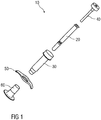
- Figure 1 shows an exemplary embodiment of a medicament delivery device 10 according to the present invention.
- the delivery device 10 comprises a medicament container 20, a safety device 30 and a plunger 40.
- the delivery device 10 may further include a finger flange 50 and/or a cap 60.
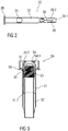
- Figure 2 shows an exemplary of a medicament container 20 according to the present invention.
- the medicament container 20 includes a barrel 22, a stopper 24 slidably disposed in the barrel 22 and a needle 26 coupled to a distal end of the barrel 22.
- the stopper 24 may be made from a rubber material.
- a proximal end of the barrel 22 includes a flange 28 which may be fully or partial circular, elliptical, square, rectangular or any other shape.
- the barrel 22 may be any size (e.g., 0.5ml, 1 ml, 2 ml, etc.) and be made of any suitable material (e.g., plastic, glass).
- the barrel 22 may be manufactured from Type I clear glass.
- the stopper 24 is made from a rubber material.
- the needle 26 is made from stainless steel.
- the needle 26 may be any gauge or length.
- a needle shield 29 may be removably coupled to the distal end of the barrel 22 to cover the needle 26.
- the needle shield 29 may be a sheath 29.1 made of, for example, rubber or elastomer latex.
- the needle shield 29 may further include a casing 29.2 made of, for example, polypropylene or any other similar material.
- the casing 29.2 may be disposed partially or entirely on an outer surface of the sheath 29.1.
- the casing 29.2 may provide further support to the sheath 29.1 to, for example, prevent the needle 26 from bending or puncturing the sheath 29.1. When the needle shield 29 is removed, the needle 26 is exposed.
- FIG. 3 shows an exemplary embodiment of a safety device 30 according to the present invention.
- the safety device 30 comprises a first sheath 31 arranged telescopically with a second sheath 32, and the sheaths 31, 32 which are biased relative to each other by a spring 33.
- the sheaths Prior to use, one of the sheaths is in a retracted position relative to the other sheath, and after use, the one of the sheaths is in an extended position relative to the other sheath to cover the needle 26. In the extended position, the one of the sheaths is locked in the extended position to prevent retraction and uncovering of the needle 26.
- the first sheath 31 is an outer sheath
- the second sheath 32 is an inner sheath
- the second sheath 32 is movable from the retracted position to the extended position relative to the first sheath 31.
- the first sheath 31 comprises an open distal end allowing the second sheath 32 to move from the retracted position to the distal position.
- a proximal end of the first sheath 31 includes an engagement arrangement 34 adapted to engage the flange 28 of the medicament container 20.
- the engagement arrangement 34 includes a support surface 34.1 adapted to abut a distal surface of the flange 28 to prevent distal movement of the medicament container 20 relative to the first sheath 31, and one or more resilient hooks 34.2 adapted to engage the flange 28 to prevent proximal movement of the medicament container 20 relative to the first sheath 31.
- the flange 28 causes the resilient hooks 34.2 to deflect until the flange 28 is distal of the hooks 34.2, at which point the hooks 34.2 return to a non-deflected position and can abut a proximal surface of the flange 28.
- the proximal end of the first sheath 31 includes an inner ledge 35 and an outer ledge 36.
- the inner ledge 35 may be formed partially or entirely around a proximal opening of the first sheath 31.
- the outer ledge 36 may be formed partially or entirely around an outer surface of the first sheath 31.
- the first sheath 31 may have a distal portion having a first outer diameter and a proximal portion having a second outer diameter which is larger than the first outer diameter.
- the outer ledge 36 may be formed partially or entirely around the larger second outer diameter to provide a support surface for a user's fingers.
- the first sheath 31 is made from polycarbonate
- the second sheath is made from copolyesther
- the spring 33 is made from stainless steel.
- the ramps 42.3 engage the resilient projections which engage the resilient arms 37 such that the resilient arms 37 deflect and disengage the inner ledge 35.
- the force of the spring 33 pushes the second sheath 32 distally relative to the first sheath 31 from the retracted position to the extended position.
- the second sheath 32 is locked in the extended position, because the resilient arms 37 abut a stop surface 31.1 (shown in Figure 3 ) on the first sheath 31 preventing the second sheath 32 from moving proximally relative to the first sheath 31 from the extended position.
- the plunger 40 is made from polypropylene.
- the safety device 30 and the plunger 40 may be as described in U.S. Patent Application Publication No. 2002/0193746 , the entire disclosure of which is expressly incorporated herein by reference.
- Figures 5A and 5B show an exemplary embodiment of a cap 60 according to the present invention.
- the cap 60 comprises cylindrical portion 61 having a first outer diameter and a disc portion 62 having a second outer diameter larger than the second outer diameter.
- the cylindrical portion 61 includes a thru hole 61.1 adapted to accommodate the needle shield 29.
- the disc portion 62 may include a thru hole coaxial with the thru hole 61.1 or may include a full or partial cover to fully or partially enclose the thru hole 61.1. When assembled a proximal end of the cylindrical portion 61 may abut a distal end of the first sheath 31.
- a gripping surface 63 may be coupled to the cap 60.
- the gripping surface 63 includes a proximal portion 63.1 and a distal portion 63.2.
- the proximal portion 63.1 may be coupled to all or part of an outer surface of the cylindrical portion 61 of the cap 60 and/or all or part of a proximal surface of the disc portion 62.
- the distal portion 63.2 may be coupled to all of part of an inner surface of the cylindrical portion 61 of the cap 60 and/or all or part of a distal surface of the disc portion 62.
- the proximal portion 63.1 or the distal portion 63.2 may be disposed partially or entirely around a circumference of the disc portion 62.
- the gripping surface 63 may be made from a material having a lower durometer than the material comprising the cap 60.
- the gripping surface 63 may be elastomer thermoplastic.
- the gripping surface 63 may provide an easily grippable and supportive surface for a user to grip to remove the cap 60 from the medicament delivery device 10.
- any part of the gripping surface 63 may include one or more frictional features (e.g., ridges, bumps, etc.) to ensure that the user's fingers do not slip when gripping and removing the cap 60.
- Figure 6 shows an exemplary embodiment of a cap 60 coupled to the medicament delivery device 10.
- the distal portion 63.2 of the gripping surface 63 is partially disposed on the inner surface of the cylindrical portion 61 of the cap 60.
- a thickness of the distal portion 63.2 may decrease along the length of the inner surface in the proximal direction.
- a proximal end of the distal portion 63.2 along the length of the inner surface may include a ramp feature 63.2.1 adapted to receive and guide the needle shield 29, e.g., during assembly.
- the distal portion 63.2 of the gripping surface 63 is adapted to frictionally engage the needle shield 29, such that when the cap 60 is pulled away from the medicament delivery device 10, the needle shield 29 is removed.
- all or part of the distal portion 63.2 may include one or more engagement features (e.g., a barb, a hook, a projection, etc.) adapted to engage the needle shield 29 (or any feature thereof, e.g., a slot, a channel, a recess, etc.) when the needle shield 29 is inserted into the cap 60.
- the distal portion 63.2 may include one or more separate pieces of material. For example, a first piece of material may be disposed on the inner surface of the cylindrical portion 61 and a second piece of material may be disposed on the distal surface of the disc portion 62.
- a thru-hole 62.1 may be formed in the disc portion 62, e.g., for molding the gripping surface 63.
- the cap 60 and/or the gripping surface 63 may include one or more indicia for indicating how to remove the cap 60.
- all or part of the cap 60 may be a first color and all or part of the gripping surface 63 may be a second color different from the first color to signify that this is the needle end of the device 10.
- one or more words or symbols may be disposed on the cap 60 and/or the gripping surface 63.
- an arrow point in the distal direction and/or the words "PULL” or "DO NOT TWIST” may be disposed on the cap 60 and/or the gripping surface 63.
- Figure 7 shows an exemplary embodiment a finger flange 50 according to the present invention.
- Figure 8 shows another exemplary embodiment of a finger flange 500 according to the present invention.
- Figure 9 shows a proximal view of a finger flange 50/500 according to the present invention.
- the central recess 71 may further include a retaining wall 71.2 adapted to abut at least a portion of the outer ledge 36 to prevent rotation of the first sheath 31 relative to the finger flange 50/500.
- One or more resilient clips 72 are disposed within or adjacent the central recess 71 and adapted to engage the outer ledge 36. When the finger flange 50/500 is coupled to the first sheath 31, the clips 72 deflect to accommodate the outer ledge 36 and then return to a non-deflected position to engage the outer ledge 36.
- the bearing surface 71.1 may not be recessed but may be in plane with the proximal surface of the finger flange 50/500.
- the retaining wall 71.2 and the clips 72 may extend proximally from the flat surface.
- the proximal surface of the finger flange 50/500 may include one or more lateral recesses 73 adjacent the central recess 71.
- the lateral recesses 73 may be formed to create a hinge effect when supporting the user's fingers.
- the lateral recesses 73 may further decrease weight of the finger flange 50/500 and reduce constraints on molding.
- Figure 7 shows an exemplary embodiment of the finger flange 50 disposed on the outer sheath 31.
- the finger flange 50 includes one or more support portions 51 extending radially from a central portion 52.
- the proximal surface of the finger flange 50 is substantially flat and distal surfaces of the support portions 51 and the central portion 52 are concave relative to the proximal surface (e.g., when the finger flange 50 is placed on a flat surface such that the proximal surface engages the flat surface).
- the support portion 51 may include a support surface 53.
- the support surface 53 may be made, e. g.
- the support surface 53 may be elastomer thermoplastic.
- the gripping surface 53 may provide a surface for a user's finger when administering an injection.
- any part of the support surface 53 may include one or more frictional features (e.g., ridges, bumps, etc.) to ensure that the user's fingers do not slip when administering the injection.
- the support surface 53 may be formed without such surface structures.
- a radial distance R between an outer radial surface 54 and an inner radial surface 55 may be approximately 20mm.
- the radial distance may be increased, and the support portions may be larger.
- the finger flange 50 may be made from polypropylene or acrylonitrile butadiene styrene and the support surfaces 53 may be made from elastomer thermoplastic.
- Figure 8 shows an exemplary embodiment of the finger flange 500 disposed on the outer sheath 31.
- the finger flange 500 includes one or more support portions 501 extending radially from a central portion 502. Proximal and distal surfaces of the support portions 501 are concave, and proximal and distal surfaces of the central portion 502 are substantially flat (e.g., approximately perpendicular to a longitudinal axis of the first sheath 31).
- the support portion 501 may include a support surface 503.
- the support surface 503 may be made, e. g. by overmolding or by two-shot injection molding, from a material having a lower durometer than the material comprising the finger flange 500.
- the support surface 503 may be elastomer thermoplastic.
- the gripping surface 503 may provide a surface for a user's finger when administering an injection.
- any part of the support surface 503 may include one or more frictional features (e.g., ridges, bumps, etc.) to ensure that the user's fingers do not slip when administering the injection.
- the support surface 53 may be formed without such surface structures. While the exemplary embodiment of the invention shows two support portions 501 extending radially in a wing-like fashion from the central portion 502, those of skill in the art will understand that any number of support portions 501 in any shape, size or dimension may be utilized based on the intended application.
- a radial distance R between an outer radial surface 504 and an inner radial surface 505 may be approximately 20mm.
- the radial distance may be increased, and the support portions may be larger.
- the finger flange 500 may be made from polypropylene or acrylonitrile butadiene styrene and the support surfaces 503 may be made from elastomer thermoplastic.
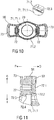
- Figure 10 shows an exemplary embodiment of a finger flange 50 according to the present invention.
- a proximal surface of the finger flange 50 includes a hole 70 adapted to receive the first sheath 31.
- a diameter of the hole 70 is approximately equal to an outer diameter of the first sheath 31.
- a central recess 71 may be formed around the hole 70 and be adapted to accommodate a proximal portion of the first sheath 31.
- the central recess 71 may include a bearing surface 71.1 adapted to abut a distal face of the outer ledge 36.
- the central recess 71 may further include a retaining wall 71.2 adapted to abut at least a portion of the outer ledge 36 to prevent rotation of the first sheath 31 relative to the finger flange 50.
- One or more resilient clips 72 are disposed within or adjacent the central recess 71 and adapted to engage the outer ledge 36. When the finger flange 50 is coupled to the first sheath 31, the clips 72 deflect to accommodate the outer ledge 36 and then return to a non-deflected position to engage the outer ledge 36.
- the bearing surface 71.1 may not be recessed but may be in plane with the proximal surface of the finger flange 50.
- the retaining wall 71.2 and the clips 72 may extend proximally from the flat surface.
- a protrusion 71.3 is arranged in the retaining wall 71.2 in a manner to engage a respective recess (not illustrated) in the outer ledge 36 so as to avoid and/or limit relative rotation between the first sheath 31 and the finger flange 50.
- the protrusion 71.3 could be arranged in the hole 70 in a manner to engage a respective recess (not illustrated) in the first sheath 31.
- the protrusion 71.3 has an arcuate shape. Those skilled in the art will understand that the protrusion 71.3 may take any other form. Likewise, it would be possible to arrange the protrusion 71.3 on the first sheath 31 or on the outer ledge 36 in a manner to let it engage a corresponding recess in the retaining wall 71.2 or in the hole 70.
- FIG 11 shows a sectional detail view of an exemplary embodiment of a finger flange 50 according to the present invention.
- the resilient clip 72 comprises a transverse beam 72.1 originating from the finger flange 50 and extending in a radial inward direction I.
- the transverse beam 72.1 may be arranged substantially in parallel with the finger flange 50, i.e. substantially at right angles with respect to the first sheath 31 to be received within the hole 70.
- the resilient clip 72 furthermore comprises a longitudinal beam 72.2 originating from a radial inward end of the transverse beam 72.1 and extending in a proximal direction P.
- a hook comprising a slope surface 72.3 and a block surface 72.4 is arranged on the proximal end of the longitudinal beam 72.2 and extends in the radial inward direction I.
- the slope surface 72.3 allows for inserting the outer ledge 36 of the first sheath 31 in a distal direction D, wherein the outer ledge 36 engages the slope surface 72.3 increasingly deflecting it in a radial outward direction O due to the resilient properties of the transverse beam 72.1 and/or the longitudinal beam 72.2.
- the resilient clip 72 relaxes and returns in the radial inward direction I.
- the distally facing block surface 72.4 thus engages a proximal face of the outer ledge 36 preventing it from returning in the proximal direction P.
- Figure 12 shows a sectional detail view of an exemplary embodiment of a finger flange 50 according to the present invention.
- the embodiment substantially corresponds to the embodiment of figure 11 .
- the embodiment of figure 12 differs from the embodiment of figure 11 in that the transverse beam 72.1 comprises a hinge 72.1.1, i.e. a section in which a thickness of the transverse beam 72.1 is reduced with respect to the rest of the transverse beam 72.1.
- the hinge 72.1.1 has a thickness of approximately 30% to 70%, in particular 40% to 60% of the thickness of the rest of the transverse beam 72.1.
- the hinge 72.1.1 is arranged adjacent the longitudinal beam 72.2.
- cap 60 While exemplary embodiments of the components and/or portions of the cap 60 are described as having certain shapes (e.g., cylinders, discs, etc.) with certain properties that connote a shape (e.g., a diameter, circumference, etc.), those of skill in the art will understand that the cap 60 according to present invention is not limited to any shape or size, but may be adapted for any application or use.
- certain shapes e.g., cylinders, discs, etc.
- properties that connote a shape e.g., a diameter, circumference, etc.
- drug or “medicament”, as used herein, means a pharmaceutical formulation containing at least one pharmaceutically active compound, wherein in one embodiment the pharmaceutically active compound has a molecular weight up to 1500 Da and/or is a peptide, a proteine, a polysaccharide, a vaccine, a DNA, a RNA, an enzyme, an antibody or a fragment thereof, a hormone or an oligonucleotide, or a mixture of the above-mentioned pharmaceutically active compound, wherein in a further embodiment the pharmaceutically active compound is useful for the treatment and/or prophylaxis of diabetes mellitus or complications associated with diabetes mellitus such as diabetic retinopathy, thromboembolism disorders such as deep vein or pulmonary thromboembolism, acute coronary syndrome (ACS), angina, myocardial infarction, cancer, macular degeneration, inflammation, hay fever, atherosclerosis and/or rheumatoid arthritis, wherein in a further
- Insulin analogues are for example Gly(A21), Arg(B31), Arg(B32) human insulin; Lys(B3), Glu(B29) human insulin; Lys(B28), Pro(B29) human insulin; Asp(B28) human insulin; human insulin, wherein proline in position B28 is replaced by Asp, Lys, Leu, Val or Ala and wherein in position B29 Lys may be replaced by Pro; Ala(B26) human insulin; Des(B28-B30) human insulin; Des(B27) human insulin and Des(B30) human insulin.
- Insulin derivates are for example B29-N-myristoyl-des(B30) human insulin; B29-N-palmitoyl-des(B30) human insulin; B29-N-myristoyl human insulin; B29-N-palmitoyl human insulin; B28-N-myristoyl LysB28ProB29 human insulin; B28-N-palmitoyl-LysB28ProB29 human insulin; B30-N-myristoyl-ThrB29LysB30 human insulin; B30-N-palmitoyl- ThrB29LysB30 human insulin; B29-N-(N-palmitoyl-Y-glutamyl)-des(B30) human insulin; B29-N-(N-lithocholyl-Y-glutamyl)-des(B30) human insulin; B29-N-( ⁇ -carboxyheptadecanoyl)-des(B30) human insulin and B29-N-(w-carbox
- Exendin-4 derivatives are for example selected from the following list of compounds:
- Hormones are for example hypophysis hormones or hypothalamus hormones or regulatory active peptides and their antagonists as listed in Rote Liste, ed. 2008, Chapter 50 , such as Gonadotropine (Follitropin, Lutropin, Choriongonadotropin, Menotropin), Somatropine (Somatropin), Desmopressin, Terlipressin, Gonadorelin, Triptorelin, Leuprorelin, Buserelin, Nafarelin, Goserelin.
- Gonadotropine Follitropin, Lutropin, Choriongonadotropin, Menotropin
- Somatropine Somatropin
- Desmopressin Terlipressin
- Gonadorelin Triptorelin
- Leuprorelin Buserelin
- Nafarelin Goserelin.
- Antibodies are globular plasma proteins (-150 kDa) that are also known as immunoglobulins which share a basic structure. As they have sugar chains added to amino acid residues, they are glycoproteins.
- the basic functional unit of each antibody is an immunoglobulin (Ig) monomer (containing only one Ig unit); secreted antibodies can also be dimeric with two Ig units as with IgA, tetrameric with four Ig units like teleost fish IgM, or pentameric with five Ig units, like mammalian IgM.
- Ig immunoglobulin
- Distinct heavy chains differ in size and composition; ⁇ and ⁇ contain approximately 450 amino acids and ⁇ approximately 500 amino acids, while ⁇ and ⁇ have approximately 550 amino acids.
- Each heavy chain has two regions, the constant region (C H ) and the variable region (V H ).
- the constant region is essentially identical in all antibodies of the same isotype, but differs in antibodies of different isotypes.
- Heavy chains ⁇ , ⁇ and ⁇ have a constant region composed of three tandem Ig domains, and a hinge region for added flexibility; heavy chains ⁇ and ⁇ have a constant region composed of four immunoglobulin domains.
- the variable region of the heavy chain differs in antibodies produced by different B cells, but is the same for all antibodies produced by a single B cell or B cell clone.
- the variable region of each heavy chain is approximately 110 amino acids long and is composed of a single Ig domain.
- a light chain has two successive domains: one constant domain (CL) and one variable domain (VL).
- CL constant domain
- VL variable domain
- the approximate length of a light chain is 211 to 217 amino acids.
- Each antibody contains two light chains that are always identical; only one type of light chain, ⁇ or ⁇ , is present per antibody in mammals.
- variable (V) regions are responsible for binding to the antigen, i.e. for its antigen specificity.
- VL variable light
- VH variable heavy chain
- CDRs Complementarity Determining Regions
- Pharmaceutically acceptable salts are for example acid addition salts and basic salts.
- Acid addition salts are e.g. HCI or HBr salts.
- Basic salts are e.g. salts having a cation selected from alkali or alkaline, e.g. Na+, or K+, or Ca2+, or an ammonium ion N+(R1)(R2)(R3)(R4), wherein R1 to R4 independently of each other mean: hydrogen, an optionally substituted C1-C6-alkyl group, an optionally substituted C2-C6-alkenyl group, an optionally substituted C6-C10-aryl group, or an optionally substituted C6-C10-heteroaryl group.
Landscapes
- Health & Medical Sciences (AREA)
- Engineering & Computer Science (AREA)
- Life Sciences & Earth Sciences (AREA)
- Animal Behavior & Ethology (AREA)
- Anesthesiology (AREA)
- Biomedical Technology (AREA)
- Heart & Thoracic Surgery (AREA)
- Hematology (AREA)
- Veterinary Medicine (AREA)
- Vascular Medicine (AREA)
- General Health & Medical Sciences (AREA)
- Public Health (AREA)
- Environmental & Geological Engineering (AREA)
- Infusion, Injection, And Reservoir Apparatuses (AREA)
- Medical Preparation Storing Or Oral Administration Devices (AREA)
- Accommodation For Nursing Or Treatment Tables (AREA)
- Closures For Containers (AREA)
Abstract
Description
- The invention relates to a safety device for a medicament container.
- Administering an injection is a process which presents a number of risks and challenges for users and healthcare professionals, both mental and physical. Medicament delivery devices typically fall into two categories - manual devices and auto-injectors. In a conventional manual device, manual force is required to drive a medicament through a needle. This is typically done by some form of button / plunger that has to be continuously pressed during the injection. A conventional auto-injector may provide the force for administering the medicament by a spring, and a trigger button or other mechanism may be used to activate the injection.
- For use of manual devices and autoinjectors, safety and usability are of the utmost importance. Thus, there remains a need for improved medicament delivery devices which include components or mechanisms for user and patient safety (e.g., to prevent misuse, needlestick, etc.) and enhanced usability (e.g., making the device easier to user before, during and after an injection to improve dose accuracy and compliance).
- It is an object of the present invention to provide an improved safety device for a medicament container.
- In an exemplary embodiment, a safety device for a medicament container according to the present invention comprises a first sheath having a first ledge and a second ledge, a second sheath telescopically arranged with the first sheath and releasably coupled to the first ledge, and a finger flange having at least one resilient clip adapted to engage the second ledge first sheath.
- In an exemplary embodiment the resilient clip comprises a transverse beam extending in a radial inward direction, a longitudinal beam extending from the transverse beam in a proximal direction, a hook comprising a slope surface and a block surface extending from the longitudinal beam in the radial inward direction, wherein during insertion of the outer ledge in a distal direction the second ledge engages the slope surface increasingly deflecting the resilient clip in a radial outward direction, wherein, after the second ledge has passed the slope surface the resilient clip relaxes and the second ledge (36) engages the block surface preventing the second ledge from returning in the proximal direction.
- In an exemplary embodiment of the transverse beam comprises a hinge in the shape of a a section with a reduced thickness compared to the rest of the transverse beam.
- In an exemplary embodiment the hinge has a thickness of approximately 30% to 70%, in particular 40% to 60% of the thickness of the rest of the transverse beam.
- In an exemplary embodiment a protrusion is arranged on one of the finger flange and the first sheath, the protrusion arranged to engage a recess in the other one of the finger flange and the first sheath so as to limit relative rotation between the first sheath and the finger flange.
- In an exemplary embodiment, the finger flange comprises a hole adapted to receive the first sheath. The finger flange comprises a central recess disposed adjacent to the hole adapted to receive the second ledge.
- In an exemplary embodiment, the finger flange comprises a retaining wall adapted to abut the second ledge. The retaining wall abuts an entire periphery of the second ledge.
- In an exemplary embodiment, the finger flange comprises at least one lateral recess disposed adjacent the hole.
- In an exemplary embodiment, the finger flange comprises a central portion and at least one support portion extending radially from the central portion. The at least one support portion includes a support surface and wherein the support surface is made from a first material and the support portion is made from a second material, and wherein the first material has a lower durometer than the second material. The support surface may include one or more frictional features.
- In an exemplary embodiment the support surface is formed by overmolding or by two-shot injection molding.
- In an exemplary embodiment, a radial distance between an outer radial surface and an outer diameter of the hole is approximately 20mm.
- In an exemplary embodiment, the central portion comprises a substantially flat proximal surface and a concave distal surface, and the at least one support portion comprises a substantially flat proximal surface and a concave distal surface.
- In an exemplary embodiment, the central portion comprises a substantially flat proximal surface and a substantially flat distal surface, and the at least one support portion comprises a concave proximal surface and a concave distal surface.
- In an exemplary embodiment, a medicament delivery device according to the present invention comprises a medicament container and a safety device according to any one of the exemplary embodiments.
- Further scope of applicability of the present invention will become apparent from the detailed description given hereinafter. However, it should be understood that the detailed description and specific examples, while indicating preferred embodiments of the invention, are given by way of illustration only, since various changes and modifications within the spirit and scope of the invention will become apparent to those skilled in the art from this detailed description.
- The present invention will become more fully understood from the detailed description given hereinbelow and the accompanying drawings which are given by way of illustration only, and thus, are not limitive of the present invention, and wherein:
- Figure 1
- shows an exemplary embodiment of a medicament delivery device according to the present invention,
- Figure 2
- shows an exemplary embodiment of a medicament container according to the present invention,
- Figure 3
- shows an exemplary embodiment of a safety device according to the present invention,
- Figures 4A and 4B
- show an exemplary embodiment of a plunger according to the present invention,
- Figures 5A and 5B
- show an exemplary embodiment of a cap according to the present invention,
- Figure 6
- shows an exemplary embodiment of a cap according to the present invention,
- Figure 7
- shows an exemplary embodiment of a finger flange according to the present invention,
- Figure 8
- shows another exemplary embodiment of a finger flange according to the present invention, and
- Figure 9
- shows an exemplary embodiment of a finger flange according to the present invention, and
- Figure 10
- shows an exemplary embodiment of a finger flange according to the present invention,
- Figure 11
- shows a sectional detail view of an exemplary embodiment of a finger flange according to the present invention, and
- Figure 12
- shows a sectional detail view of an exemplary embodiment of a finger flange according to the present invention.
- Corresponding parts are marked with the same reference symbols in all figures. Detailed Description
-
Figure 1 shows an exemplary embodiment of amedicament delivery device 10 according to the present invention. In an exemplary embodiment, thedelivery device 10 comprises amedicament container 20, asafety device 30 and aplunger 40. Thedelivery device 10 may further include afinger flange 50 and/or acap 60. -
Figure 2 shows an exemplary of amedicament container 20 according to the present invention. In the exemplary embodiment, themedicament container 20 includes abarrel 22, astopper 24 slidably disposed in thebarrel 22 and aneedle 26 coupled to a distal end of thebarrel 22. In an exemplary embodiment, thestopper 24 may be made from a rubber material. A proximal end of thebarrel 22 includes aflange 28 which may be fully or partial circular, elliptical, square, rectangular or any other shape. Thebarrel 22 may be any size (e.g., 0.5ml, 1 ml, 2 ml, etc.) and be made of any suitable material (e.g., plastic, glass). In an exemplary embodiment, thebarrel 22 may be manufactured from Type I clear glass. In an exemplary embodiment, thestopper 24 is made from a rubber material. In an exemplary embodiment, theneedle 26 is made from stainless steel. Theneedle 26 may be any gauge or length. - In an exemplary embodiment, a
needle shield 29 may be removably coupled to the distal end of thebarrel 22 to cover theneedle 26. In an exemplary embodiment, theneedle shield 29 may be a sheath 29.1 made of, for example, rubber or elastomer latex. - In another exemplary embodiment, the
needle shield 29 may further include a casing 29.2 made of, for example, polypropylene or any other similar material. The casing 29.2 may be disposed partially or entirely on an outer surface of the sheath 29.1. The casing 29.2 may provide further support to the sheath 29.1 to, for example, prevent theneedle 26 from bending or puncturing the sheath 29.1. When theneedle shield 29 is removed, theneedle 26 is exposed. -
Figure 3 shows an exemplary embodiment of asafety device 30 according to the present invention. In the exemplary embodiment, thesafety device 30 comprises afirst sheath 31 arranged telescopically with asecond sheath 32, and thesheaths spring 33. Prior to use, one of the sheaths is in a retracted position relative to the other sheath, and after use, the one of the sheaths is in an extended position relative to the other sheath to cover theneedle 26.
In the extended position, the one of the sheaths is locked in the extended position to prevent retraction and uncovering of theneedle 26. - In the exemplary embodiment shown in
Figure 3 , thefirst sheath 31 is an outer sheath, and thesecond sheath 32 is an inner sheath, and thesecond sheath 32 is movable from the retracted position to the extended position relative to thefirst sheath 31. Thefirst sheath 31 comprises an open distal end allowing thesecond sheath 32 to move from the retracted position to the distal position. A proximal end of thefirst sheath 31 includes anengagement arrangement 34 adapted to engage theflange 28 of themedicament container 20. In an exemplary embodiment, theengagement arrangement 34 includes a support surface 34.1 adapted to abut a distal surface of theflange 28 to prevent distal movement of themedicament container 20 relative to thefirst sheath 31, and one or more resilient hooks 34.2 adapted to engage theflange 28 to prevent proximal movement of themedicament container 20 relative to thefirst sheath 31. When themedicament container 20 is inserted into thefirst sheath 31, theflange 28 causes the resilient hooks 34.2 to deflect until theflange 28 is distal of the hooks 34.2, at which point the hooks 34.2 return to a non-deflected position and can abut a proximal surface of theflange 28. - In an exemplary embodiment, the proximal end of the
first sheath 31 includes aninner ledge 35 and anouter ledge 36. Theinner ledge 35 may be formed partially or entirely around a proximal opening of thefirst sheath 31. Theouter ledge 36 may be formed partially or entirely around an outer surface of thefirst sheath 31. As shown in the exemplary embodiment inFigure 3 , thefirst sheath 31 may have a distal portion having a first outer diameter and a proximal portion having a second outer diameter which is larger than the first outer diameter. Theouter ledge 36 may be formed partially or entirely around the larger second outer diameter to provide a support surface for a user's fingers. - In an exemplary embodiment, the
second sheath 32 comprises an open distal end allowing theneedle 26 to pass through when thesecond sheath 32 is in the retracted position. A proximal end of thesecond sheath 32 includes one or moreresilient arms 37 adapted to releaseably engage theinner ledge 35 to maintain thesecond sheath 32 in the retracted position against the force of thespring 33 which biases thesecond sheath 32 towards the extended position. When thesecond sheath 32 is in the retracted position, theresilient arms 37 are radially biased to engage theinner ledge 35. - In an exemplary embodiment, the
first sheath 31 is made from polycarbonate, the second sheath is made from copolyesther, and thespring 33 is made from stainless steel. -
Figures 4A and 4B show an exemplary embodiment of aplunger 40 according to the present invention. In the exemplary embodiment, theplunger 40 includes adistal end 41 adapted to engage thestopper 24, aproximal end 42 adapted to be pressed by a user, and astem 43 connecting the distal and proximal ends 41, 42.Figure 4B shows a partial cross-section of an exemplary embodiment of theproximal end 42 of theplunger 40. In the exemplary embodiment, theproximal end 42 includes a bearing surface 42.1 adapted to receive a user's finger. The bearing surface 42.1 may be flat (perpendicular relative to a longitudinal axis of the medicament container 20) or have a partially or entirely concave or convex surface. In another exemplary embodiment, the bearing surface 42.1 may have one or more surface elements (e.g., ridges, bumps, etc.) adapted to frictionally engage the user's finger to prevent it from slipping off the bearing surface 42.1 during use. Theproximal end 42 further includes a radial surface 42.2 having a distal end that is adapted to engage one or more resilient projections on thefirst sheath 31 that deflect upon engagement with the radial surface 42.2 to engage the one or moreresilient arms 37 on thesecond sheath 32 when theplunger 40 has been pressed a sufficient distance relative to themedicament container 20. In an exemplary embodiment, the distal end of the radial surface 42.2 may comprise one or more ramps 42.3 adapted to engage the resilient projections such that the resilient rejectionsresilient arms 37 deflect and disengage theinner ledge 35. - In an exemplary use, when the
plunger 40 is pressed a sufficient distance, the ramps 42.3 engage the resilient projections which engage theresilient arms 37 such that theresilient arms 37 deflect and disengage theinner ledge 35. The force of thespring 33 pushes thesecond sheath 32 distally relative to thefirst sheath 31 from the retracted position to the extended position. Thesecond sheath 32 is locked in the extended position, because theresilient arms 37 abut a stop surface 31.1 (shown inFigure 3 ) on thefirst sheath 31 preventing thesecond sheath 32 from moving proximally relative to thefirst sheath 31 from the extended position. - In an exemplary embodiment, the
plunger 40 is made from polypropylene. - In an exemplary embodiment, the
safety device 30 and theplunger 40 may be as described inU.S. Patent Application Publication No. 2002/0193746 , the entire disclosure of which is expressly incorporated herein by reference. -
Figures 5A and 5B show an exemplary embodiment of acap 60 according to the present invention. In the exemplary embodiment, thecap 60 comprisescylindrical portion 61 having a first outer diameter and adisc portion 62 having a second outer diameter larger than the second outer diameter. Thecylindrical portion 61 includes a thru hole 61.1 adapted to accommodate theneedle shield 29. Thedisc portion 62 may include a thru hole coaxial with the thru hole 61.1 or may include a full or partial cover to fully or partially enclose the thru hole 61.1. When assembled a proximal end of thecylindrical portion 61 may abut a distal end of thefirst sheath 31. - In an exemplary embodiment, the
cap 60 may be made from polypropylene. - In an exemplary embodiment, a gripping surface 63 may be coupled to the
cap 60. In the exemplary embodiment, the gripping surface 63 includes a proximal portion 63.1 and a distal portion 63.2. The proximal portion 63.1 may be coupled to all or part of an outer surface of thecylindrical portion 61 of thecap 60 and/or all or part of a proximal surface of thedisc portion 62. The distal portion 63.2 may be coupled to all of part of an inner surface of thecylindrical portion 61 of thecap 60 and/or all or part of a distal surface of thedisc portion 62. In another exemplary embodiment, the proximal portion 63.1 or the distal portion 63.2 may be disposed partially or entirely around a circumference of thedisc portion 62. - In an exemplary embodiment, the gripping surface 63 may be made from a material having a lower durometer than the material comprising the
cap 60. In an exemplary embodiment, the gripping surface 63 may be elastomer thermoplastic. The gripping surface 63 may provide an easily grippable and supportive surface for a user to grip to remove thecap 60 from themedicament delivery device 10. In an exemplary embodiment, any part of the gripping surface 63 may include one or more frictional features (e.g., ridges, bumps, etc.) to ensure that the user's fingers do not slip when gripping and removing thecap 60. -
Figure 6 shows an exemplary embodiment of acap 60 coupled to themedicament delivery device 10. In the exemplary embodiment, the distal portion 63.2 of the gripping surface 63 is partially disposed on the inner surface of thecylindrical portion 61 of thecap 60. In an exemplary embodiment, a thickness of the distal portion 63.2 may decrease along the length of the inner surface in the proximal direction. A proximal end of the distal portion 63.2 along the length of the inner surface may include a ramp feature 63.2.1 adapted to receive and guide theneedle shield 29, e.g., during assembly. The distal portion 63.2 of the gripping surface 63 is adapted to frictionally engage theneedle shield 29, such that when thecap 60 is pulled away from themedicament delivery device 10, theneedle shield 29 is removed. In another exemplary embodiment, all or part of the distal portion 63.2 may include one or more engagement features (e.g., a barb, a hook, a projection, etc.) adapted to engage the needle shield 29 (or any feature thereof, e.g., a slot, a channel, a recess, etc.) when theneedle shield 29 is inserted into thecap 60. In an exemplary embodiment, the distal portion 63.2 may include one or more separate pieces of material. For example, a first piece of material may be disposed on the inner surface of thecylindrical portion 61 and a second piece of material may be disposed on the distal surface of thedisc portion 62. A thru-hole 62.1 may be formed in thedisc portion 62, e.g., for molding the gripping surface 63. - In an exemplary embodiment, the
cap 60 and/or the gripping surface 63 may include one or more indicia for indicating how to remove thecap 60. For example, all or part of thecap 60 may be a first color and all or part of the gripping surface 63 may be a second color different from the first color to signify that this is the needle end of thedevice 10. In another exemplary embodiment, one or more words or symbols may be disposed on thecap 60 and/or the gripping surface 63. For example, an arrow point in the distal direction and/or the words "PULL" or "DO NOT TWIST" may be disposed on thecap 60 and/or the gripping surface 63. -
Figure 7 shows an exemplary embodiment afinger flange 50 according to the present invention.Figure 8 shows another exemplary embodiment of afinger flange 500 according to the present invention.Figure 9 shows a proximal view of afinger flange 50/500 according to the present invention. - As shown in the exemplary embodiment in
Figure 9 , a proximal surface of thefinger flange 50/500 include ahole 70 adapted to receive thefirst sheath 31. In an exemplary embodiment, a diameter of thehole 70 is approximately equal to an outer diameter of thefirst sheath 31. A central recess 71 may be formed around thehole 70 and be adapted to accommodate a proximal portion of thefirst sheath 31. For example, the central recess 71 may include a bearing surface 71.1 adapted to abut a distal face of theouter ledge 36. The central recess 71 may further include a retaining wall 71.2 adapted to abut at least a portion of theouter ledge 36 to prevent rotation of thefirst sheath 31 relative to thefinger flange 50/500. One or moreresilient clips 72 are disposed within or adjacent the central recess 71 and adapted to engage theouter ledge 36. When thefinger flange 50/500 is coupled to thefirst sheath 31, theclips 72 deflect to accommodate theouter ledge 36 and then return to a non-deflected position to engage theouter ledge 36. - In another exemplary embodiment, the bearing surface 71.1 may not be recessed but may be in plane with the proximal surface of the
finger flange 50/500. In this exemplary embodiment, the retaining wall 71.2 and theclips 72 may extend proximally from the flat surface. - In an exemplary embodiment, the proximal surface of the
finger flange 50/500 may include one or morelateral recesses 73 adjacent the central recess 71. The lateral recesses 73 may be formed to create a hinge effect when supporting the user's fingers. The lateral recesses 73 may further decrease weight of thefinger flange 50/500 and reduce constraints on molding. -
Figure 7 shows an exemplary embodiment of thefinger flange 50 disposed on theouter sheath 31. In the exemplary embodiment, thefinger flange 50 includes one ormore support portions 51 extending radially from acentral portion 52. The proximal surface of thefinger flange 50 is substantially flat and distal surfaces of thesupport portions 51 and thecentral portion 52 are concave relative to the proximal surface (e.g., when thefinger flange 50 is placed on a flat surface such that the proximal surface engages the flat surface). Thesupport portion 51 may include asupport surface 53. In an exemplary embodiment, thesupport surface 53 may be made, e. g. by overmolding or by two-shot injection molding, from a material having a lower durometer than the material comprising thefinger flange 50. In an exemplary embodiment, thesupport surface 53 may be elastomer thermoplastic. The grippingsurface 53 may provide a surface for a user's finger when administering an injection. In an exemplary embodiment, any part of thesupport surface 53 may include one or more frictional features (e.g., ridges, bumps, etc.) to ensure that the user's fingers do not slip when administering the injection. Likewise, thesupport surface 53 may be formed without such surface structures. While the exemplary embodiment of the invention shows twosupport portions 51 extending radially in a wing-like fashion from thecentral portion 52, those of skill in the art will understand that any number ofsupport portions 51 in any shape, size or dimension may be utilized based on the intended application. For example, a radial distance R between an outerradial surface 54 and an innerradial surface 55 may be approximately 20mm. However, for use with elderly or arthritic patients, the radial distance may be increased, and the support portions may be larger. - In an exemplary embodiment, the
finger flange 50 may be made from polypropylene or acrylonitrile butadiene styrene and the support surfaces 53 may be made from elastomer thermoplastic. -
Figure 8 shows an exemplary embodiment of thefinger flange 500 disposed on theouter sheath 31. In the exemplary embodiment, thefinger flange 500 includes one ormore support portions 501 extending radially from acentral portion 502. Proximal and distal surfaces of thesupport portions 501 are concave, and proximal and distal surfaces of thecentral portion 502 are substantially flat (e.g., approximately perpendicular to a longitudinal axis of the first sheath 31). Thesupport portion 501 may include asupport surface 503. In an exemplary embodiment, thesupport surface 503 may be made, e. g. by overmolding or by two-shot injection molding, from a material having a lower durometer than the material comprising thefinger flange 500. In an exemplary embodiment, thesupport surface 503 may be elastomer thermoplastic. Thegripping surface 503 may provide a surface for a user's finger when administering an injection. In an exemplary embodiment, any part of thesupport surface 503 may include one or more frictional features (e.g., ridges, bumps, etc.) to ensure that the user's fingers do not slip when administering the injection. Likewise, thesupport surface 53 may be formed without such surface structures. While the exemplary embodiment of the invention shows twosupport portions 501 extending radially in a wing-like fashion from thecentral portion 502, those of skill in the art will understand that any number ofsupport portions 501 in any shape, size or dimension may be utilized based on the intended application. For example, a radial distance R between an outerradial surface 504 and an innerradial surface 505 may be approximately 20mm. However, for use with elderly or arthritic patients, the radial distance may be increased, and the support portions may be larger. - In an exemplary embodiment, the
finger flange 500 may be made from polypropylene or acrylonitrile butadiene styrene and the support surfaces 503 may be made from elastomer thermoplastic. -
Figure 10 shows an exemplary embodiment of afinger flange 50 according to the present invention. A proximal surface of thefinger flange 50 includes ahole 70 adapted to receive thefirst sheath 31. In an exemplary embodiment, a diameter of thehole 70 is approximately equal to an outer diameter of thefirst sheath 31. A central recess 71 may be formed around thehole 70 and be adapted to accommodate a proximal portion of thefirst sheath 31. For example, the central recess 71 may include a bearing surface 71.1 adapted to abut a distal face of theouter ledge 36. The central recess 71 may further include a retaining wall 71.2 adapted to abut at least a portion of theouter ledge 36 to prevent rotation of thefirst sheath 31 relative to thefinger flange 50. One or moreresilient clips 72 are disposed within or adjacent the central recess 71 and adapted to engage theouter ledge 36. When thefinger flange 50 is coupled to thefirst sheath 31, theclips 72 deflect to accommodate theouter ledge 36 and then return to a non-deflected position to engage theouter ledge 36. - In another exemplary embodiment, the bearing surface 71.1 may not be recessed but may be in plane with the proximal surface of the
finger flange 50. In this exemplary embodiment, the retaining wall 71.2 and theclips 72 may extend proximally from the flat surface. - In an exemplary embodiment, the proximal surface of the
finger flange 50 may include one or morelateral recesses 73 adjacent the central recess 71. The lateral recesses 73 may be formed to create a hinge effect when supporting the user's fingers. The lateral recesses 73 may further decrease weight of thefinger flange 50 and reduce constraints on molding. - In an exemplary embodiment a protrusion 71.3 is arranged in the retaining wall 71.2 in a manner to engage a respective recess (not illustrated) in the
outer ledge 36 so as to avoid and/or limit relative rotation between thefirst sheath 31 and thefinger flange 50. In another exemplary embodiment the protrusion 71.3 could be arranged in thehole 70 in a manner to engage a respective recess (not illustrated) in thefirst sheath 31. In the illustrated embodiment the protrusion 71.3 has an arcuate shape. Those skilled in the art will understand that the protrusion 71.3 may take any other form. Likewise, it would be possible to arrange the protrusion 71.3 on thefirst sheath 31 or on theouter ledge 36 in a manner to let it engage a corresponding recess in the retaining wall 71.2 or in thehole 70. -
Figure 11 shows a sectional detail view of an exemplary embodiment of afinger flange 50 according to the present invention. Theresilient clip 72 comprises a transverse beam 72.1 originating from thefinger flange 50 and extending in a radial inward direction I. The transverse beam 72.1 may be arranged substantially in parallel with thefinger flange 50, i.e. substantially at right angles with respect to thefirst sheath 31 to be received within thehole 70. Theresilient clip 72 furthermore comprises a longitudinal beam 72.2 originating from a radial inward end of the transverse beam 72.1 and extending in a proximal direction P. A hook comprising a slope surface 72.3 and a block surface 72.4 is arranged on the proximal end of the longitudinal beam 72.2 and extends in the radial inward direction I. The slope surface 72.3 allows for inserting theouter ledge 36 of thefirst sheath 31 in a distal direction D, wherein theouter ledge 36 engages the slope surface 72.3 increasingly deflecting it in a radial outward direction O due to the resilient properties of the transverse beam 72.1 and/or the longitudinal beam 72.2. Once theouter ledge 36 has passed the slope surface 72.3 during insertion theresilient clip 72 relaxes and returns in the radial inward direction I. The distally facing block surface 72.4 thus engages a proximal face of theouter ledge 36 preventing it from returning in the proximal direction P. -
Figure 12 shows a sectional detail view of an exemplary embodiment of afinger flange 50 according to the present invention. The embodiment substantially corresponds to the embodiment offigure 11 . However, the embodiment offigure 12 differs from the embodiment offigure 11 in that the transverse beam 72.1 comprises a hinge 72.1.1, i.e. a section in which a thickness of the transverse beam 72.1 is reduced with respect to the rest of the transverse beam 72.1. In an exemplary embodiment the hinge 72.1.1 has a thickness of approximately 30% to 70%, in particular 40% to 60% of the thickness of the rest of the transverse beam 72.1. In an exemplary embodiment the hinge 72.1.1 is arranged adjacent the longitudinal beam 72.2. - While exemplary embodiments of the components and/or portions of the
cap 60 are described as having certain shapes (e.g., cylinders, discs, etc.) with certain properties that connote a shape (e.g., a diameter, circumference, etc.), those of skill in the art will understand that thecap 60 according to present invention is not limited to any shape or size, but may be adapted for any application or use. - While exemplary embodiments of the present invention are described as being made from certain materials, those of skill in the art will understand that other materials (and/or combinations of materials) may be utilized based on the intended application or use.
- The term "drug" or "medicament", as used herein, means a pharmaceutical formulation containing at least one pharmaceutically active compound,
wherein in one embodiment the pharmaceutically active compound has a molecular weight up to 1500 Da and/or is a peptide, a proteine, a polysaccharide, a vaccine, a DNA, a RNA, an enzyme, an antibody or a fragment thereof, a hormone or an oligonucleotide, or a mixture of the above-mentioned pharmaceutically active compound,
wherein in a further embodiment the pharmaceutically active compound is useful for the treatment and/or prophylaxis of diabetes mellitus or complications associated with diabetes mellitus such as diabetic retinopathy, thromboembolism disorders such as deep vein or pulmonary thromboembolism, acute coronary syndrome (ACS), angina, myocardial infarction, cancer, macular degeneration, inflammation, hay fever, atherosclerosis and/or rheumatoid arthritis,
wherein in a further embodiment the pharmaceutically active compound comprises at least one peptide for the treatment and/or prophylaxis of diabetes mellitus or complications associated with diabetes mellitus such as diabetic retinopathy,
wherein in a further embodiment the pharmaceutically active compound comprises at least one human insulin or a human insulin analogue or derivative, glucagon-like peptide (GLP-1) or an analogue or derivative thereof, or exendin-3 or exendin-4 or an analogue or derivative of exendin-3 or exendin-4. - Insulin analogues are for example Gly(A21), Arg(B31), Arg(B32) human insulin; Lys(B3), Glu(B29) human insulin; Lys(B28), Pro(B29) human insulin; Asp(B28) human insulin; human insulin, wherein proline in position B28 is replaced by Asp, Lys, Leu, Val or Ala and wherein in position B29 Lys may be replaced by Pro; Ala(B26) human insulin; Des(B28-B30) human insulin; Des(B27) human insulin and Des(B30) human insulin. Insulin derivates are for example B29-N-myristoyl-des(B30) human insulin; B29-N-palmitoyl-des(B30) human insulin; B29-N-myristoyl human insulin; B29-N-palmitoyl human insulin; B28-N-myristoyl LysB28ProB29 human insulin; B28-N-palmitoyl-LysB28ProB29 human insulin; B30-N-myristoyl-ThrB29LysB30 human insulin; B30-N-palmitoyl- ThrB29LysB30 human insulin; B29-N-(N-palmitoyl-Y-glutamyl)-des(B30) human insulin; B29-N-(N-lithocholyl-Y-glutamyl)-des(B30) human insulin; B29-N-(ω-carboxyheptadecanoyl)-des(B30) human insulin and B29-N-(w-carboxyheptadecanoyl) human insulin.
- Exendin-4 for example means Exendin-4(1-39), a peptide of the sequence H-His-Gly-Glu-Gly-Thr-Phe-Thr-Ser-Asp-Leu-Ser-Lys-Gln-Met-Glu-Glu-Glu-Ala-Val-Arg-Leu-Phe-Ile-Glu-Trp-Leu-Lys-Asn-Gly-Gly-Pro-Ser-Ser-Gly-Ala-Pro-Pro-Pro-Ser-NH2.
- Exendin-4 derivatives are for example selected from the following list of compounds:
- H-(Lys)4-des Pro36, des Pro37 Exendin-4(1-39)-NH2,
- H-(Lys)5-des Pro36, des Pro37 Exendin-4(1-39)-NH2,
- des Pro36 Exendin-4(1-39),
- des Pro36 [Asp28] Exendin-4(1-39),
- des Pro36 [IsoAsp28] Exendin-4(1-39),
- des Pro36 [Met(O)14, Asp28] Exendin-4(1-39),
- des Pro36 [Met(O)14, IsoAsp28] Exendin-4(1-39),
- des Pro36 [Trp(O2)25, Asp28] Exendin-4(1-39),
- des Pro36 [Trp(O2)25, IsoAsp28] Exendin-4(1-39),
- des Pro36 [Met(O)14 Trp(O2)25, Asp28] Exendin-4(1-39),
- des Pro36 [Met(O)14 Trp(O2)25, IsoAsp28] Exendin-4(1-39); or
- des Pro36 [Asp28] Exendin-4(1-39),
- des Pro36 [IsoAsp28] Exendin-4(1-39),
- des Pro36 [Met(O)14, Asp28] Exendin-4(1-39),
- des Pro36 [Met(O)14, IsoAsp28] Exendin-4(1-39),
- des Pro36 [Trp(O2)25, Asp28] Exendin-4(1-39),
- des Pro36 [Trp(O2)25, IsoAsp28] Exendin-4(1-39),
- des Pro36 [Met(O)14 Trp(O2)25, Asp28] Exendin-4(1-39),
- des Pro36 [Met(O)14 Trp(O2)25, IsoAsp28] Exendin-4(1-39),
wherein the group -Lys6-NH2 may be bound to the C-terminus of the Exendin-4 derivative; - or an Exendin-4 derivative of the sequence
- des Pro36 Exendin-4(1-39)-Lys6-NH2 (AVE0010),
- H-(Lys)6-des Pro36 [Asp28] Exendin-4(1-39)-Lys6-NH2,
- des Asp28 Pro36, Pro37, Pro38Exendin-4(1-39)-NH2,
- H-(Lys)6-des Pro36, Pro38 [Asp28] Exendin-4(1-39)-NH2,
- H-Asn-(Glu)5des Pro36, Pro37, Pro38 [Asp28] Exendin-4(1-39)-NH2,
- des Pro36, Pro37, Pro38 [Asp28] Exendin-4(1-39)-(Lys)6-NH2,
- H-(Lys)6-des Pro36, Pro37, Pro38 [Asp28] Exendin-4(1-39)-(Lys)6-NH2,
- H-Asn-(Glu)5-des Pro36, Pro37, Pro38 [Asp28] Exendin-4(1-39)-(Lys)6-NH2,
- H-(Lys)6-des Pro36 [Trp(O2)25, Asp28] Exendin-4(1-39)-Lys6-NH2,
- H-des Asp28 Pro36, Pro37, Pro38 [Trp(O2)25] Exendin-4(1-39)-NH2,
- H-(Lys)6-des Pro36, Pro37, Pro38 [Trp(O2)25, Asp28] Exendin-4(1-39)-NH2,
- H-Asn-(Glu)5-des Pro36, Pro37, Pro38 [Trp(O2)25, Asp28] Exendin-4(1-39)-NH2,
- des Pro36, Pro37, Pro38 [Trp(O2)25, Asp28] Exendin-4(1-39)-(Lys)6-NH2,
- H-(Lys)6-des Pro36, Pro37, Pro38 [Trp(O2)25, Asp28] Exendin-4(1-39)-(Lys)6-NH2,
- H-Asn-(Glu)5-des Pro36, Pro37, Pro38 [Trp(O2)25, Asp28] Exendin-4(1-39)-(Lys)6-NH2,
- H-(Lys)6-des Pro36 [Met(O)14, Asp28] Exendin-4(1-39)-Lys6-NH2,
- des Met(O)14 Asp28 Pro36, Pro37, Pro38 Exendin-4(1-39)-NH2,
- H-(Lys)6-desPro36, Pro37, Pro38 [Met(O)14, Asp28] Exendin-4(1-39)-NH2,
- H-Asn-(Glu)5-des Pro36, Pro37, Pro38 [Met(O)14, Asp28] Exendin-4(1-39)-NH2,
- des Pro36, Pro37, Pro38 [Met(O)14, Asp28] Exendin-4(1-39)-(Lys)6-NH2,
- H-(Lys)6-des Pro36, Pro37, Pro38 [Met(O)14, Asp28] Exendin-4(1-39)-(Lys)6-NH2,
- H-Asn-(Glu)5 des Pro36, Pro37, Pro38 [Met(O)14, Asp28] Exendin-4(1-39)-(Lys)6-NH2,
- H-Lys6-des Pro36 [Met(O)14, Trp(O2)25, Asp28] Exendin-4(1-39)-Lys6-NH2,
- H-des Asp28 Pro36, Pro37, Pro38 [Met(O)14, Trp(O2)25] Exendin-4(1-39)-NH2,
- H-(Lys)6-des Pro36, Pro37, Pro38 [Met(O)14, Asp28] Exendin-4(1-39)-NH2,
- H-Asn-(Glu)5-des Pro36, Pro37, Pro38 [Met(O)14, Trp(O2)25, Asp28] Exendin-4(1-39)-NH2,
- des Pro36, Pro37, Pro38 [Met(O)14, Trp(O2)25, Asp28] Exendin-4(1-39)-(Lys)6-NH2, H-(Lys)6-des Pro36, Pro37, Pro38 [Met(O)14, Trp(O2)25, Asp28] Exendin-4(S1-39)-(Lys)6-NH2,
- H-Asn-(Glu)5-des Pro36, Pro37, Pro38 [Met(O)14, Trp(O2)25, Asp28] Exendin-4(1-39)-(Lys)6-NH2;
or a pharmaceutically acceptable salt or solvate of any one of the afore-mentioned Exendin-4 derivative. - Hormones are for example hypophysis hormones or hypothalamus hormones or regulatory active peptides and their antagonists as listed in Rote Liste, ed. 2008, , such as Gonadotropine (Follitropin, Lutropin, Choriongonadotropin, Menotropin), Somatropine (Somatropin), Desmopressin, Terlipressin, Gonadorelin, Triptorelin, Leuprorelin, Buserelin, Nafarelin, Goserelin.
- A polysaccharide is for example a glucosaminoglycane, a hyaluronic acid, a heparin, a low molecular weight heparin or an ultra low molecular weight heparin or a derivative thereof, or a sulphated, e.g. a poly-sulphated form of the above-mentioned polysaccharides, and/or a pharmaceutically acceptable salt thereof. An example of a pharmaceutically acceptable salt of a poly-sulphated low molecular weight heparin is enoxaparin sodium.
- Antibodies are globular plasma proteins (-150 kDa) that are also known as immunoglobulins which share a basic structure. As they have sugar chains added to amino acid residues, they are glycoproteins. The basic functional unit of each antibody is an immunoglobulin (Ig) monomer (containing only one Ig unit); secreted antibodies can also be dimeric with two Ig units as with IgA, tetrameric with four Ig units like teleost fish IgM, or pentameric with five Ig units, like mammalian IgM.
- The Ig monomer is a "Y"-shaped molecule that consists of four polypeptide chains; two identical heavy chains and two identical light chains connected by disulfide bonds between cysteine residues. Each heavy chain is about 440 amino acids long; each light chain is about 220 amino acids long. Heavy and light chains each contain intrachain disulfide bonds which stabilize their folding. Each chain is composed of structural domains called Ig domains. These domains contain about 70-110 amino acids and are classified into different categories (for example, variable or V, and constant or C) according to their size and function. They have a characteristic immunoglobulin fold in which two β sheets create a "sandwich" shape, held together by interactions between conserved cysteines and other charged amino acids.
- There are five types of mammalian Ig heavy chain denoted by α, δ, ε, γ, and µ. The type of heavy chain present defines the isotype of antibody; these chains are found in IgA, IgD, IgE, IgG, and IgM antibodies, respectively.
- Distinct heavy chains differ in size and composition; α and γ contain approximately 450 amino acids and δ approximately 500 amino acids, while µ and ε have approximately 550 amino acids. Each heavy chain has two regions, the constant region (CH) and the variable region (VH). In one species, the constant region is essentially identical in all antibodies of the same isotype, but differs in antibodies of different isotypes. Heavy chains γ, α and δ have a constant region composed of three tandem Ig domains, and a hinge region for added flexibility; heavy chains µ and ε have a constant region composed of four immunoglobulin domains. The variable region of the heavy chain differs in antibodies produced by different B cells, but is the same for all antibodies produced by a single B cell or B cell clone. The variable region of each heavy chain is approximately 110 amino acids long and is composed of a single Ig domain.
- In mammals, there are two types of immunoglobulin light chain denoted by λ and κ. A light chain has two successive domains: one constant domain (CL) and one variable domain (VL). The approximate length of a light chain is 211 to 217 amino acids. Each antibody contains two light chains that are always identical; only one type of light chain, κ or λ, is present per antibody in mammals.
- Although the general structure of all antibodies is very similar, the unique property of a given antibody is determined by the variable (V) regions, as detailed above. More specifically, variable loops, three each the light (VL) and three on the heavy (VH) chain, are responsible for binding to the antigen, i.e. for its antigen specificity. These loops are referred to as the Complementarity Determining Regions (CDRs). Because CDRs from both VH and VL domains contribute to the antigen-binding site, it is the combination of the heavy and the light chains, and not either alone, that determines the final antigen specificity.
- An "antibody fragment" contains at least one antigen binding fragment as defined above, and exhibits essentially the same function and specificity as the complete antibody of which the fragment is derived from. Limited proteolytic digestion with papain cleaves the Ig prototype into three fragments. Two identical amino terminal fragments, each containing one entire L chain and about half an H chain, are the antigen binding fragments (Fab). The third fragment, similar in size but containing the carboxyl terminal half of both heavy chains with their interchain disulfide bond, is the crystalizable fragment (Fc). The Fc contains carbohydrates, complement-binding, and FcR-binding sites. Limited pepsin digestion yields a single F(ab')2 fragment containing both Fab pieces and the hinge region, including the H-H interchain disulfide bond. F(ab')2 is divalent for antigen binding. The disulfide bond of F(ab')2 may be cleaved in order to obtain Fab'. Moreover, the variable regions of the heavy and light chains can be fused together to form a single chain variable fragment (scFv).
- Pharmaceutically acceptable salts are for example acid addition salts and basic salts. Acid addition salts are e.g. HCI or HBr salts. Basic salts are e.g. salts having a cation selected from alkali or alkaline, e.g. Na+, or K+, or Ca2+, or an ammonium ion N+(R1)(R2)(R3)(R4), wherein R1 to R4 independently of each other mean: hydrogen, an optionally substituted C1-C6-alkyl group, an optionally substituted C2-C6-alkenyl group, an optionally substituted C6-C10-aryl group, or an optionally substituted C6-C10-heteroaryl group. Further examples of pharmaceutically acceptable salts are described in "Remington's Pharmaceutical Sciences" 17. ed. Alfonso R. Gennaro (Ed.), Mark Publishing Company, Easton, Pa., U.S.A., 1985 and in Encyclopedia of Pharmaceutical Technology.
- Pharmaceutically acceptable solvates are for example hydrates.
- Those of skill in the art will understand that modifications (additions and/or removals) of various components of the apparatuses, methods and/or systems and embodiments described herein may be made without departing from the full scope and spirit of the present invention, which encompass such modifications and any and all equivalents thereof.
- A list of embodiments follows:
- Embodiment 1: A safety device (30) for a medicament container (20) comprising:
- a first sheath (31) having a first ledge (35) and a second ledge (36);
- a second sheath (32) telescopically arranged with the first sheath and releasably coupled to the first ledge (35); and
- a finger flange (50, 500) having at least one resilient clip (72) adapted to engage the second ledge (36) of the first sheath (31).
- Embodiment 2: The safety device (30) of embodiment 1, wherein the resilient clip (72) comprises a transverse beam (72.1) extending in a radial inward direction (I), a longitudinal beam (72.2) extending from the transverse beam (72.1) in a proximal direction (P), a hook comprising a slope surface (72.3) and a block surface (72.4) extending from the longitudinal beam (72.2) in the radial inward direction (I), wherein during insertion of the outer ledge (36) in a distal direction (D) the second ledge (36) engages the slope surface (72.3) increasingly deflecting the resilient clip (72) in a radial outward direction (O), wherein, after the second ledge (36) has passed the slope surface (72.3) the resilient clip (72) relaxes and the second ledge (36) engages the block surface (72.4) preventing the second ledge (36) from returning in the proximal direction (P).
- Embodiment 3: The safety device of embodiment 2, wherein the transverse beam (72.1) comprises a hinge (72.1.1) in the shape of a a section with a reduced thickness compared to the rest of the transverse beam (72.1).
- Embodiment 4: The safety device of embodiment 3, wherein the hinge (72.1.1) has a thickness of approximately 30% to 70%, in particular 40% to 60% of the thickness of the rest of the transverse beam (72.1).
- Embodiment 5: The safety device of any one of the embodiments 1 to 4, wherein a protrusion (71.3) is arranged on one of the finger flange (50) and the first sheath (31), the protrusion (71.2) arranged to engage a recess in the other one of the finger flange (50) and the first sheath (31) so as to limit relative rotation between the first sheath (31) and the finger flange (50).
- Embodiment 6: The safety device (30) according to any one of the embodiments 1 to 5, wherein the finger flange (50, 500) comprises a hole (70) adapted to receive the first sheath (31).
- Embodiment 7: The safety device (30) according to embodiment 6, wherein the finger flange (50, 500) comprises a central recess (71) disposed adjacent to the hole (70) adapted to recieve the second ledge (36).
- Embodiment 8: The safety device (30) according to any one of the embodiments 1 to 7, wherein the finger flange (50, 500) comprises a retaining wall (71.2) adapted to abut the second ledge (36).
- Embodiment 9: The safety device (30) according to embodiment 8, wherein the retaining wall (71.2) abuts an entire periphery of the second ledge (36).
- Embodiment 10: The safety device (30) according to one of the embodiments 6 to 9, wherein the finger flange (50, 500) comprises at least one lateral recess (73) disposed adjacent the hole (70).
- Embodiment 11: The safety device (30) according to any one of the embodiments 1 to 10, wherein the finger flange (50, 500) comprises a central portion (52, 502) and at least one support portion (51, 501) extending radially from the central portion (52, 502).
- Embodiment 12: The safety device (30) according to embodiment 11, wherein the at least one support portion (51, 501) includes a support surface (53, 503), and wherein the support surface (53, 503) is made from a first material and the support portion (51, 501) is made from a second material, and wherein the first material has a lower durometer than the second material.
- Embodiment 13: The safety device (30) according to embodiment 11 or 12, wherein the support surface (53, 503) includes one or more frictional features.
- Embodiment 14: The safety device (30) according to one of the embodiments 12 or 13, wherein the support surface (53) is formed by overmolding or by two-shot injection molding.
- Embodiment 15: The safety device (30) according to any one of the embodiments 6 to 14, wherein a radial distance (R) between an outer radial surface (54) and an outer diameter of the hole (70) is approximately 20mm.
- Embodiment 16: The safety device (30) according to any one of the embodiments 11 to 15, wherein the central portion (52) comprises a substantially flat proximal surface and a concave distal surface.
- Embodiment 17: The safety device (30) according to embodiment 16, wherein the at least one support portion (51, 501) comprises a substantially flat proximal surface and a concave distal surface.
- Embodiment 18: The safety device (30) according to any one of embodiments 11 to 15, wherein the central portion (52) comprises a substantially flat proximal surface and a substantially flat distal surface.
- Embodiment 19: The safety device (30) according to embodiment 18, wherein the at least one support portion (51, 501) comprises a concave proximal surface and a concave distal surface.
- Embodiment 20: A medicament delivery device (10) comprising:
- a medicament container (20); and
- a safety device (30) according to any one of the embodiments 1 to 19.
-
- 10
- medicament delivery device
- 20
- medicament container
- 22
- barrel
- 24
- stopper
- 26
- needle
- 28
- flange
- 29
- needle shield
- 29.1
- sheath
- 29.2
- casing
- 30
- safety device
- 31
- first sheath
- 31.1
- stop surface
- 32
- second sheath
- 33
- spring
- 34
- engagement arrangement
- 34.1
- support surface
- 34.2
- resilient hook
- 35
- inner ledge
- 36
- outer ledge
- 37
- resilient arm
- 40
- plunger
- 41
- distal end
- 42
- proximal end
- 42.1
- bearing surface
- 42.2
- radial surface
- 42.3
- ramp
- 43
- stem
- 50
- finger flange
- 51
- support portion
- 52
- central portion
- 53
- support surface
- 54
- outer radial surface
- 55
- inner radial surface
- 60
- cap
- 61
- cylindrical portion
- 61.1
- thru hole
- 62
- disc portion
- 62.1
- thru hole
- 63
- gripping surface
- 63.1
- proximal portion
- 63.2
- distal portion
- 63.2.1
- ramp feature
- 70
- hole
- 71
- central recess
- 71.1
- bearing surface
- 71.2
- retaining wall
- 71.3
- protrusion
- 72
- resilient clip
- 72.1
- transverse beam
- 72.1.1
- hinge
- 72.2
- longitudinal beam
- 72.3
- slope surface
- 72.4
- block surface
- 73
- lateral recess
- 500
- finger flange
- 501
- support portion
- 502
- central portion
- 503
- support surface
- 504
- outer radial surface
- 505
- inner radial surface
- D
- distal direction
- I
- radial inward direction
- O
- radial outward direction
- P
- proximal direction
- R
- radial distance
Claims (15)
- A safety device (30) for a medicament container (20) comprising:a first sheath (31) having a first ledge (35) and a second ledge (36);a second sheath (32) telescopically arranged with the first sheath and releasably coupled to the first ledge (35); anda finger flange (50, 500) having at least one resilient clip (72) adapted to engage the second ledge (36) of the first sheath (31),
wherein the finger flange (50, 500) comprises a central portion (52, 502) and at least one support portion (51, 501) extending radially from the central portion (52, 502)
wherein the at least one support portion (51, 501) includes a support surface (53, 503), and wherein the support surface (53, 503) is made from a first material and the support portion (51, 501) is made from a second material, and wherein the first material has a lower durometer than the second material. - A safety device (30) for a medicament container (20) comprising:a first sheath (31) having a first ledge (35) and a second ledge (36);a second sheath (32) telescopically arranged with the first sheath and releasably coupled to the first ledge (35); anda finger flange (50, 500) having at least one resilient clip (72) adapted to engage the second ledge (36) of the first sheath (31),
wherein the finger flange (50, 500) comprises a central portion (52, 502) and at least one support portion (51, 501) extending radially from the central portion (52, 502), wherein the support surface (53, 503) includes one or more frictional features,
wherein the support surface (53) is formed by overmolding or by two-shot injection molding. - The safety device (30) of claim 1, wherein the support surface (53, 503) includes one or more frictional features.
- The safety device (30) of claim 1 or 3, wherein the support surface (53) is formed by overmolding or by two-shot injection molding.
- The safety device (30) of claim 2, wherein the at least one support portion (51, 501) includes a support surface (53, 503), and wherein the support surface (53, 503) is made from a first material and the support portion (51, 501) is made from a second material, and wherein the first material has a lower durometer than the second material.
- The safety device (30) of claim 1 or 5, wherein the support portion (51, 501) is made from polypropylene or acrylonitrile butadiene styrene and the support surfaces (53, 503) is made from elastomer thermoplastic.
- The safety device (30) according to any one of the preceding claims, wherein the resilient clip (72) comprises a transverse beam (72.1) extending in a radial inward direction (I), a longitudinal beam (72.2) extending from the transverse beam (72.1) in a proximal direction (P), a hook comprising a slope surface (72.3) and a block surface (72.4) extending from the longitudinal beam (72.2) in the radial inward direction (I), wherein during insertion of the outer ledge (36) in a distal direction (D) the second ledge (36) engages the slope surface (72.3) increasingly deflecting the resilient clip (72) in a radial outward direction (O), wherein, after the second ledge (36) has passed the slope surface (72.3) the resilient clip (72) relaxes and the second ledge (36) engages the block surface (72.4) preventing the second ledge (36) from returning in the proximal direction (P).
- The safety device of claim 7, wherein the transverse beam (72.1) comprises a hinge (72.1.1) in the shape of a section with a reduced thickness compared to the rest of the transverse beam (72.1), in particular with the hinge (72.1.1) having a thickness of approximately 30% to 70%, in particular 40% to 60% of the thickness of the rest of the transverse beam (72.1).
- The safety device of any one of the preceding claims, wherein a protrusion (71.3) is arranged on one of the finger flange (50) and the first sheath (31), the protrusion (71.2) arranged to engage a recess in the other one of the finger flange (50) and the first sheath (31) so as to limit relative rotation between the first sheath (31) and the finger flange (50).
- The safety device (30) according to any one of the preceding claims, wherein the finger flange (50, 500) comprises a hole (70) adapted to receive the first sheath (31).
- The safety device (30) according to claim 10, wherein the finger flange (50, 500) comprises a central recess (71) disposed adjacent to the hole (70) adapted to receive the second ledge (36) and or wherein the finger flange (50, 500) comprises a retaining wall (71.2) adapted to abut the second ledge (36), in particular an entire periphery thereof.
- The safety device (30) according to one of the claims 10 or 11, wherein the finger flange (50, 500) comprises at least one lateral recess (73) disposed adjacent the hole (70).
- The safety device (30) according to any one of the claims 10 to 12, wherein a radial distance (R) between an outer radial surface (54) and an outer diameter of the hole (70) is approximately 20mm.
- The safety device (30) according to any one of the claims 10 to 13, wherein the central portion (52) comprises a substantially flat proximal surface and a concave distal surface or wherein the central portion (52) comprises a substantially flat proximal surface and a substantially flat distal surface.
- The safety device (30) according to claim 14, wherein the at least one support portion (51, 501) comprises a substantially flat proximal surface and a concave distal surface or wherein the at least one support portion (51, 501) comprises a concave proximal surface and a concave distal surface.
Applications Claiming Priority (4)
| Application Number | Priority Date | Filing Date | Title |
|---|---|---|---|
| EP13306179 | 2013-08-29 | ||
| PCT/EP2014/068130 WO2015028487A1 (en) | 2013-08-29 | 2014-08-27 | Safety device for a medicament container |
| EP14758114.4A EP3038683B1 (en) | 2013-08-29 | 2014-08-27 | Safety device for a medicament container |
| EP18150769.0A EP3335751B1 (en) | 2013-08-29 | 2014-08-27 | Safety device for a medicament container |
Related Parent Applications (3)
| Application Number | Title | Priority Date | Filing Date |
|---|---|---|---|
| EP14758114.4A Division EP3038683B1 (en) | 2013-08-29 | 2014-08-27 | Safety device for a medicament container |
| EP18150769.0A Division-Into EP3335751B1 (en) | 2013-08-29 | 2014-08-27 | Safety device for a medicament container |
| EP18150769.0A Division EP3335751B1 (en) | 2013-08-29 | 2014-08-27 | Safety device for a medicament container |
Publications (1)
| Publication Number | Publication Date |
|---|---|
| EP3804792A1 true EP3804792A1 (en) | 2021-04-14 |
Family
ID=49231397
Family Applications (3)
| Application Number | Title | Priority Date | Filing Date |
|---|---|---|---|
| EP14758114.4A Active EP3038683B1 (en) | 2013-08-29 | 2014-08-27 | Safety device for a medicament container |
| EP20206392.1A Pending EP3804792A1 (en) | 2013-08-29 | 2014-08-27 | Safety device for a medicament container |
| EP18150769.0A Active EP3335751B1 (en) | 2013-08-29 | 2014-08-27 | Safety device for a medicament container |
Family Applications Before (1)
| Application Number | Title | Priority Date | Filing Date |
|---|---|---|---|
| EP14758114.4A Active EP3038683B1 (en) | 2013-08-29 | 2014-08-27 | Safety device for a medicament container |
Family Applications After (1)
| Application Number | Title | Priority Date | Filing Date |
|---|---|---|---|
| EP18150769.0A Active EP3335751B1 (en) | 2013-08-29 | 2014-08-27 | Safety device for a medicament container |
Country Status (17)
| Country | Link |
|---|---|
| US (3) | US10363379B2 (en) |
| EP (3) | EP3038683B1 (en) |
| JP (1) | JP6499178B2 (en) |
| KR (1) | KR102351113B1 (en) |
| CN (1) | CN105492055B (en) |
| AR (1) | AR097470A1 (en) |
| AU (1) | AU2014314245B2 (en) |
| BR (1) | BR112016003398B1 (en) |
| DK (2) | DK3038683T3 (en) |
| ES (1) | ES2691949T3 (en) |
| IL (1) | IL244007B (en) |
| MX (1) | MX370024B (en) |
| PL (1) | PL3038683T3 (en) |
| RU (1) | RU2695560C2 (en) |
| TR (1) | TR201815155T4 (en) |
| TW (1) | TW201521818A (en) |
| WO (1) | WO2015028487A1 (en) |
Families Citing this family (7)
| Publication number | Priority date | Publication date | Assignee | Title |
|---|---|---|---|---|
| CA167339S (en) | 2016-03-02 | 2016-10-18 | Sanofi Sa | Finger flange for injection device |
| DK3458131T3 (en) * | 2016-05-18 | 2022-05-23 | Sanofi Aventis Deutschland | SLEEVE REMOVALS AND METHODS FOR COLLECTING IT |
| US20190328976A1 (en) * | 2016-06-30 | 2019-10-31 | Tech Group Europe Limited | Combination accessory finger flange and syringe with a needle-stick prevention device |
| CH712753A2 (en) | 2016-07-28 | 2018-01-31 | Tecpharma Licensing Ag | Separating a needle cap from a product container and method of mounting an injection device. |
| USD798444S1 (en) | 2016-08-31 | 2017-09-26 | Sanofi S.A. | Finger flange for injection device |
| USD960359S1 (en) * | 2020-06-19 | 2022-08-09 | Bobby Nourani | Syringe handle |
| US20230330352A1 (en) * | 2022-04-13 | 2023-10-19 | Credence Medsystems, Inc. | Needle cover management and needle hiding devices for injection systems and methods |
Citations (4)
| Publication number | Priority date | Publication date | Assignee | Title |
|---|---|---|---|---|
| US20020193746A1 (en) | 1999-12-07 | 2002-12-19 | Stephane Chevallier | Safety system for a syringe |
| US20110276026A1 (en) * | 2010-05-05 | 2011-11-10 | Dowds Philip E | Extended finger flange for syringe systems |
| WO2012145685A1 (en) * | 2011-04-20 | 2012-10-26 | Amgen Inc. | Autoinjector apparatus |
| US20130053788A1 (en) * | 2010-04-28 | 2013-02-28 | Pascal Dugand | Safety Device For A Pre-Filled Injection Syringe |
Family Cites Families (42)
| Publication number | Priority date | Publication date | Assignee | Title |
|---|---|---|---|---|
| US4643389A (en) * | 1984-12-27 | 1987-02-17 | American Hospital Supply Corporation | Tubing occlusion clip |
| US4636198A (en) * | 1985-11-18 | 1987-01-13 | Mallinckrodt, Inc. | Power syringe with volume reducing adapter |
| FR2642651A1 (en) * | 1989-02-03 | 1990-08-10 | Frank Boumendil | PROTECTIVE CAP FOR THE NEEDLE OF AN INJECTION SYRINGE |
| US5192271A (en) * | 1991-11-25 | 1993-03-09 | Kalb Irvin M | Device and method for effecting an erection |
| US6159184A (en) | 1997-03-10 | 2000-12-12 | Safety Syringes, Inc. | Disposable self-shielding unit dose syringe guard |
| JPH11178923A (en) * | 1997-12-22 | 1999-07-06 | Shiseido Co Ltd | Flange for syringe |
| US6027502A (en) * | 1998-01-29 | 2000-02-22 | Desai; Ashvin H. | Surgical apparatus providing tool access and replaceable irrigation pump cartridge |
| US20050171486A1 (en) * | 1999-05-10 | 2005-08-04 | Hochman Mark N. | Safety syringe |
| WO2001008546A2 (en) * | 1999-07-29 | 2001-02-08 | Baxter International Inc. | Sampling tube holder for blood sampling system |
| US6837877B2 (en) * | 1999-08-23 | 2005-01-04 | Becton, Dickinson And Company | Safety shield assembly |
| US6623459B1 (en) | 2000-05-05 | 2003-09-23 | Safety Syringes, Inc. | Passive needle guard for syringes |
| US6613022B1 (en) | 2000-05-05 | 2003-09-02 | Safety Syringes, Inc. | Passive needle guard for syringes |
| ES2605353T3 (en) * | 2000-08-02 | 2017-03-14 | Becton, Dickinson And Company | Pen needle system and safety shield |
| FR2835753B1 (en) * | 2002-02-11 | 2004-10-29 | Plastef Investissements | SAFETY SUPPORT DEVICE FOR A SYRINGE AND ASSEMBLY OF SUCH A DEVICE AND A SYRINGE |
| US20040167476A1 (en) * | 2003-02-24 | 2004-08-26 | Westbye Lars Tommy | Tamper evident needle guard for syringes |
| FR2861310B1 (en) | 2003-10-22 | 2006-09-22 | Plastef Investissements | SECURE INJECTION SYRINGE DEVICE |
| WO2005044428A1 (en) * | 2003-11-07 | 2005-05-19 | Gambro Lundia Ab | End-cap assembly with pump hose for a filter and filter comprising such an end-cap assembly |
| US7666169B2 (en) * | 2003-11-25 | 2010-02-23 | Medrad, Inc. | Syringe and syringe plungers for use with medical injectors |
| GB0509952D0 (en) * | 2005-05-16 | 2005-06-22 | Glaxo Group Ltd | Fault indicator |
| GB0624470D0 (en) * | 2006-12-07 | 2007-01-17 | Sardrette Guernsey Ltd | Dosage delivery device |
| RU2441567C2 (en) * | 2007-03-30 | 2012-02-10 | Эллидженс Корпорейшн | Hydronic applicator with angular extended head |
| SG147319A1 (en) * | 2007-04-11 | 2008-11-28 | Agency Science Tech & Res | Safety guard for syringe needle |
| US8864675B2 (en) * | 2007-06-28 | 2014-10-21 | W. L. Gore & Associates, Inc. | Catheter |
| ES2532598T3 (en) * | 2007-09-25 | 2015-03-30 | Becton Dickinson France | Device for automatic injection |
| CN104324438B (en) | 2008-01-11 | 2017-06-16 | Ucb医药有限公司 | For the delivery system of patient with rheumatoid arthritis |
| GB2463071A (en) * | 2008-09-02 | 2010-03-03 | Owen Mumford Ltd | Auto-injector syringe with safety shield |
| GB0823066D0 (en) * | 2008-12-18 | 2009-01-28 | Medical House Plc The | Safety syringe for autoinjector |
| WO2010116832A1 (en) * | 2009-03-30 | 2010-10-14 | テルモ株式会社 | Syringe needle assembly and medicament injection device |
| EP3421067B1 (en) * | 2009-05-29 | 2021-12-15 | Ypsomed AG | Injection device, especially auto-injector, comprising an anti-pricking mechanism and/or overload protection for a product container |
| GB2475917B (en) * | 2009-12-07 | 2015-12-16 | Medical House Ltd | Syringe flange protector |
| FR2961403B1 (en) * | 2010-06-17 | 2013-06-14 | Rexam Healthcare La Verpillier | SET OF A SYRINGE AND A SAFETY DEVICE |
| TWI464002B (en) * | 2010-11-08 | 2014-12-11 | Shl Group Ab | Container holder assembly and medicament delivery device assembly |
| US20120123349A1 (en) * | 2010-11-15 | 2012-05-17 | Thomas Chun | Syringe sharp tip guard |
| EP2707061B1 (en) * | 2011-05-12 | 2016-03-23 | West Pharmaceutical Services, Inc. | Adapter for a syringe |
| US20130144255A1 (en) * | 2011-12-06 | 2013-06-06 | Robert J. Cohn | Syringe assemblies including a safety shield for a needle |
| EP2830678A4 (en) * | 2012-03-29 | 2015-12-02 | Biogen Ma Inc | Delivery device and components thereof |
| ES2869202T3 (en) * | 2012-06-18 | 2021-10-25 | Fresenius Kabi Deutschland Gmbh | Cannula line system for the puncture of central subcutaneous access lines |
| JP2015536714A (en) * | 2012-11-02 | 2015-12-24 | ノボ・ノルデイスク・エー/エス | Drug delivery device having a needle actuator operated by a shield |
| US8591463B1 (en) * | 2013-03-08 | 2013-11-26 | Teva Pharmaceutical Industries Ltd. | Re-useable injector device for syringe |
| FR3004506B1 (en) * | 2013-04-15 | 2015-11-06 | Sartorius Stedim Biotech | SECURE FLUID CONNECTION. |
| USD790691S1 (en) * | 2015-07-28 | 2017-06-27 | West Pharmaceutical Services, Inc. | Finger flange |
| US10537683B2 (en) * | 2016-11-03 | 2020-01-21 | Johnson & Johnson Surgical Vision, Inc. | Syringe finger grip |
-
2014
- 2014-08-27 TW TW103129447A patent/TW201521818A/en unknown
- 2014-08-27 JP JP2016537276A patent/JP6499178B2/en active Active
- 2014-08-27 AR ARP140103212A patent/AR097470A1/en active IP Right Grant
- 2014-08-27 PL PL14758114T patent/PL3038683T3/en unknown
- 2014-08-27 MX MX2016002591A patent/MX370024B/en active IP Right Grant
- 2014-08-27 DK DK14758114.4T patent/DK3038683T3/en active
- 2014-08-27 CN CN201480047099.9A patent/CN105492055B/en active Active
- 2014-08-27 EP EP14758114.4A patent/EP3038683B1/en active Active
- 2014-08-27 KR KR1020167007027A patent/KR102351113B1/en active Active
- 2014-08-27 WO PCT/EP2014/068130 patent/WO2015028487A1/en not_active Ceased
- 2014-08-27 EP EP20206392.1A patent/EP3804792A1/en active Pending
- 2014-08-27 BR BR112016003398-1A patent/BR112016003398B1/en active IP Right Grant
- 2014-08-27 AU AU2014314245A patent/AU2014314245B2/en active Active
- 2014-08-27 DK DK18150769.0T patent/DK3335751T3/en active
- 2014-08-27 US US14/914,759 patent/US10363379B2/en active Active
- 2014-08-27 TR TR2018/15155T patent/TR201815155T4/en unknown
- 2014-08-27 ES ES14758114.4T patent/ES2691949T3/en active Active
- 2014-08-27 RU RU2016111346A patent/RU2695560C2/en active
- 2014-08-27 EP EP18150769.0A patent/EP3335751B1/en active Active
-
2016
- 2016-02-08 IL IL244007A patent/IL244007B/en active IP Right Grant
-
2019
- 2019-06-20 US US16/446,755 patent/US11305069B2/en active Active
-
2022
- 2022-03-31 US US17/710,241 patent/US12226620B2/en active Active
Patent Citations (4)
| Publication number | Priority date | Publication date | Assignee | Title |
|---|---|---|---|---|
| US20020193746A1 (en) | 1999-12-07 | 2002-12-19 | Stephane Chevallier | Safety system for a syringe |
| US20130053788A1 (en) * | 2010-04-28 | 2013-02-28 | Pascal Dugand | Safety Device For A Pre-Filled Injection Syringe |
| US20110276026A1 (en) * | 2010-05-05 | 2011-11-10 | Dowds Philip E | Extended finger flange for syringe systems |
| WO2012145685A1 (en) * | 2011-04-20 | 2012-10-26 | Amgen Inc. | Autoinjector apparatus |
Non-Patent Citations (2)
| Title |
|---|
| "Encyclopedia of Pharmaceutical Technology" |
| "Remington's Pharmaceutical Sciences", 1985, MARK PUBLISHING COMPANY |
Also Published As
Similar Documents
| Publication | Publication Date | Title |
|---|---|---|
| US11464916B2 (en) | Cap for a medicament container | |
| US20240390604A1 (en) | Autoinjector with an inner plunger which disengages the outer plunger to retract the syringe carrier | |
| US9061106B2 (en) | Safety device for a pre-filled syringe and an injection device | |
| US12226620B2 (en) | Safety device for a medicament container | |
| US20200001019A1 (en) | Injection Device | |
| US20150258286A1 (en) | Medicament delivery device with medicament delivery initiation indicator | |
| US9468719B2 (en) | Autoinjector | |
| EP2886148A1 (en) | Drug delivery aid | |
| HK1222353B (en) | Safety device for a medicament container | |
| HK1222352B (en) | Cap for a medicament container |
Legal Events
| Date | Code | Title | Description |
|---|---|---|---|
| PUAI | Public reference made under article 153(3) epc to a published international application that has entered the european phase |
Free format text: ORIGINAL CODE: 0009012 |
|
| STAA | Information on the status of an ep patent application or granted ep patent |
Free format text: STATUS: THE APPLICATION HAS BEEN PUBLISHED |
|
| AC | Divisional application: reference to earlier application |
Ref document number: 3335751 Country of ref document: EP Kind code of ref document: P Ref document number: 3038683 Country of ref document: EP Kind code of ref document: P |
|
| AK | Designated contracting states |
Kind code of ref document: A1 Designated state(s): AL AT BE BG CH CY CZ DE DK EE ES FI FR GB GR HR HU IE IS IT LI LT LU LV MC MK MT NL NO PL PT RO RS SE SI SK SM TR |
|
| STAA | Information on the status of an ep patent application or granted ep patent |
Free format text: STATUS: REQUEST FOR EXAMINATION WAS MADE |
|
| 17P | Request for examination filed |
Effective date: 20211014 |
|
| RBV | Designated contracting states (corrected) |
Designated state(s): AL AT BE BG CH CY CZ DE DK EE ES FI FR GB GR HR HU IE IS IT LI LT LU LV MC MK MT NL NO PL PT RO RS SE SI SK SM TR |
|
| STAA | Information on the status of an ep patent application or granted ep patent |
Free format text: STATUS: EXAMINATION IS IN PROGRESS |
|
| 17Q | First examination report despatched |
Effective date: 20230929 |