EP3041006A1 - Cooling structure for electromagnetic coil, and electromagnetic actuator - Google Patents
Cooling structure for electromagnetic coil, and electromagnetic actuator Download PDFInfo
- Publication number
- EP3041006A1 EP3041006A1 EP14843006.9A EP14843006A EP3041006A1 EP 3041006 A1 EP3041006 A1 EP 3041006A1 EP 14843006 A EP14843006 A EP 14843006A EP 3041006 A1 EP3041006 A1 EP 3041006A1
- Authority
- EP
- European Patent Office
- Prior art keywords
- electromagnetic coil
- space
- electromagnetic
- cooling
- cooling member
- Prior art date
- Legal status (The legal status is an assumption and is not a legal conclusion. Google has not performed a legal analysis and makes no representation as to the accuracy of the status listed.)
- Granted
Links
Images





Classifications
-
- H—ELECTRICITY
- H01—ELECTRIC ELEMENTS
- H01F—MAGNETS; INDUCTANCES; TRANSFORMERS; SELECTION OF MATERIALS FOR THEIR MAGNETIC PROPERTIES
- H01F7/00—Magnets
- H01F7/06—Electromagnets; Actuators including electromagnets
- H01F7/08—Electromagnets; Actuators including electromagnets with armatures
-
- H—ELECTRICITY
- H01—ELECTRIC ELEMENTS
- H01F—MAGNETS; INDUCTANCES; TRANSFORMERS; SELECTION OF MATERIALS FOR THEIR MAGNETIC PROPERTIES
- H01F27/00—Details of transformers or inductances, in general
- H01F27/08—Cooling; Ventilating
- H01F27/10—Liquid cooling
- H01F27/16—Water cooling
-
- H—ELECTRICITY
- H01—ELECTRIC ELEMENTS
- H01F—MAGNETS; INDUCTANCES; TRANSFORMERS; SELECTION OF MATERIALS FOR THEIR MAGNETIC PROPERTIES
- H01F5/00—Coils
-
- H—ELECTRICITY
- H01—ELECTRIC ELEMENTS
- H01F—MAGNETS; INDUCTANCES; TRANSFORMERS; SELECTION OF MATERIALS FOR THEIR MAGNETIC PROPERTIES
- H01F7/00—Magnets
- H01F7/06—Electromagnets; Actuators including electromagnets
-
- H—ELECTRICITY
- H02—GENERATION; CONVERSION OR DISTRIBUTION OF ELECTRIC POWER
- H02K—DYNAMO-ELECTRIC MACHINES
- H02K41/00—Propulsion systems in which a rigid body is moved along a path due to dynamo-electric interaction between the body and a magnetic field travelling along the path
- H02K41/02—Linear motors; Sectional motors
-
- H—ELECTRICITY
- H02—GENERATION; CONVERSION OR DISTRIBUTION OF ELECTRIC POWER
- H02K—DYNAMO-ELECTRIC MACHINES
- H02K9/00—Arrangements for cooling or ventilating
- H02K9/22—Arrangements for cooling or ventilating by solid heat conducting material embedded in, or arranged in contact with, the stator or rotor, e.g. heat bridges
- H02K9/227—Heat sinks
-
- H—ELECTRICITY
- H02—GENERATION; CONVERSION OR DISTRIBUTION OF ELECTRIC POWER
- H02K—DYNAMO-ELECTRIC MACHINES
- H02K2201/00—Specific aspects not provided for in the other groups of this subclass relating to the magnetic circuits
- H02K2201/18—Machines moving with multiple degrees of freedom
-
- H—ELECTRICITY
- H02—GENERATION; CONVERSION OR DISTRIBUTION OF ELECTRIC POWER
- H02K—DYNAMO-ELECTRIC MACHINES
- H02K3/00—Details of windings
- H02K3/04—Windings characterised by the conductor shape, form or construction, e.g. with bar conductors
- H02K3/24—Windings characterised by the conductor shape, form or construction, e.g. with bar conductors with channels or ducts for cooling medium between the conductors
-
- H—ELECTRICITY
- H02—GENERATION; CONVERSION OR DISTRIBUTION OF ELECTRIC POWER
- H02K—DYNAMO-ELECTRIC MACHINES
- H02K9/00—Arrangements for cooling or ventilating
- H02K9/22—Arrangements for cooling or ventilating by solid heat conducting material embedded in, or arranged in contact with, the stator or rotor, e.g. heat bridges
Definitions
- the present invention relates to a structure for cooling an electromagnetic coil for use in an electromagnetic actuator, etc.
- a plate-like cooling element is attached to an end surface, with respect to the direction of a center axis, of the electromagnetic coil (refer to Patent Document 1).
- an inlet pipe and an outlet pipe for coolant are connected to a cooling element at radially opposite end portions of an electromagnetic coil.
- Patent Document 1 Japanese Patent No. 4022181
- the cooling structure described in Patent Document 1 may potentially involve the following problem: in the case where a plurality of electromagnetic coils to which the respective cooling elements are attached are to be disposed in parallel, the inlet pipes and the outlet pipes interfere with one another. Thus, difficulty is encountered in forming a unit in which a plurality of electromagnetic coils are disposed in parallel, or further in disposing the units in parallel.
- the present invention has been conceived to solve the problem, and a primary object of the invention is to provide such a structure for cooling an end surface, with respect to an axial direction, of an electromagnetic coil that enables a plurality of the electromagnetic coils to be arbitrarily disposed in parallel.
- the electromagnetic coil has the space extending in the direction of the predetermined axis. Furthermore, the cooling member is attached to the end surface, with respect to the direction of the predetermined axis, of the electromagnetic coil, and the cooling member has the flow path for fluid internally formed.
- the inlet pipe and the outlet pipe are connected to the inlet and outlet, respectively, of the flow path of the cooling member.
- the inlet pipe and the outlet pipe extend through the space to the region outside the electromagnetic coil.
- a plurality of the electromagnetic coils are disposed with their predetermined axes juxtaposed in parallel, and the cooling member is attached to the end surfaces, with respect to the direction of the predetermined axes, of the electromagnetic coils. Furthermore, the inlet pipe is connected, within the space of any one of the electromagnetic coils, to the inlet of the flow path of the cooling member, and the outlet pipe is connected, within the space of any one of the electromagnetic coils, to the outlet of the flow path of the cooling member.
- the inlet pipe and the outlet pipe are connected to the inlet and the outlet, respectively, within the same space of the electromagnetic coil.
- the plurality of electromagnetic coils disposed with their predetermined axes juxtaposed in parallel employ a constitution similar to that of the first means, whereby the inlet pipe and the outlet pipe can be disposed within a single electromagnetic coil.
- the cooling structure comprises the first electromagnetic coil and the second electromagnetic coil each of which has the space extending in the direction of the predetermined axis and which are aligned in the direction of the predetermined axis.
- the second cooling member is provided between the first electromagnetic coil and the second electromagnetic coil. Furthermore, by utilization of the inside spaces of the first and second electromagnetic coils, the first inlet pipe and the first outlet pipe can be connected to the inlet and the outlet, respectively, of the flow path of the first cooling member while extending through the second cooling member.
- the cooling structure further comprises a second inlet pipe and a second outlet pipe connected, within the space of the second electromagnetic coil, to an inlet and an outlet, respectively, of the second cooling member and extending through the space of the second electromagnetic coil to a region outside the second electromagnetic coil.
- the above configuration includes those of the second and fourth means and thus can yield actions and effects of the second and fourth means.
- the first inlet pipe and the first outlet pipe are connected to the inlet and the outlet, respectively, within the same space of the first electromagnetic coil.
- the first inlet pipe and the first outlet pipe can be disposed within a single first electromagnetic coil.
- the cooling structure for an electromagnetic coil further comprises a second inlet pipe connected, within the space of any one of the plurality of second electromagnetic coils, to an inlet of the flow path of the second cooling member and extending through the space of the second electromagnetic coil to a region outside the second electromagnetic coil, and a second outlet pipe connected, within the space of any one of the plurality of second electromagnetic coils, to an outlet of the flow path of the second cooling member and extending through the space of the second electromagnetic coil to a region outside the second electromagnetic coil.
- the second inlet pipe and the second outlet pipe are connected to the inlet and the outlet, respectively, within the same space of the second electromagnetic coil.
- the second inlet pipe and the second outlet pipe can be disposed within a single second electromagnetic coil.
- a junction pipe is connected, by means of a first seal member, to an outer circumference of an end portion, located opposite the cooling member, of the pipe, and the junction pipe is supported, by means of a second seal member, at an outer circumference of an end portion thereof located opposite the cooling member.
- the junction pipe is connected, by means of the first seal member, to the outer circumference of an end portion, located opposite the cooling member, of the pipe. Also, the junction pipe is supported, by means of the second member, at the outer circumference of an end portion thereof located opposite the cooling member.
- force imposed on the pipe can be mitigated by the first seal member, the junction pipe and the second seal member, thereby restraining imposition of load on a connection between the cooling member and the pipe.
- the first seal member and the second seal member allow some movement of the pipe and the junction pipe, errors in connecting the pipe and in connecting the junction pipe can be absorbed.
- the cooling member is formed of alumina; the pipe is formed of titanium; and the pipe is connected to the cooling member by silver-soldering by means of a metal layer diffusion-formed on a surface of the cooling member.
- the cooling member and the pipe can be restrained from affecting magnetic fluxes generated in the electromagnetic coils. Furthermore, the metal layer diffusion-formed on the surface of the cooling member allows the pipe of titanium to be connected to the cooling member of alumina by use of silver solder.
- the electromagnetic coil comprises a conductor winding formed by winding a strip conductor by a plurality of turns around the predetermined axis, and the cooling member is attached to an end surface, with respect to the direction of the predetermined axis, of the conductor winding.
- the electromagnetic coil comprises a conductor winding formed by winding a strip conductor by a plurality of turns around the predetermined axis.
- the cooling member is attached to an end surface, with respect to the direction of the predetermined axis, of the conductor winding.
- the conductor winding can transmit heat, along the entire length in the axial direction, from its end surface to the cooling member, whereby the cooling efficiency of the conductor winding can be improved.
- Thirteenth means provides an electromagnetic actuator comprises the cooling structure for an electromagnetic coil according to any one of the first to twelfth means.
- the electromagnetic actuator can yield actions and effects similar to those yielded by the above means.
- the electromagnetic actuator further comprises a driven member which is disposed opposite the electromagnetic coils with respect to the cooling members and is two-dimensionally driven along the cooling members in response to magnetic fluxes generated in the electromagnetic coils.
- the electromagnetic actuator further comprises the driven member which is disposed opposite the electromagnetic coils with respect to the cooling members and is two-dimensionally driven along the cooling members in response to magnetic fluxes generated in the electromagnetic coils.
- the inlet pipes and the outlet pipes for flowing fluid through the corresponding cooling members cannot be connected to the cooling members at any side positions thereof and at any positions located opposite the electromagnetic coils.
- even such an electromagnetic actuator allows fluid to flow through the cooling members.
- the present embodiment is of an XY linear actuator for use in a lithographic apparatus (stepper) or the like.
- a coil unit 10 which is a component of the XY linear actuator, includes a constant-temperature plate 20, first electromagnetic coils 30 (30A, 30B, 30C), a cooling plate 40, second electromagnetic coils 50 (50A, 50B, 50C), a support plate 60, and a bed 70.
- the coil unit 10 as a whole has the form of a rectangular parallelepiped.
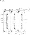
- FIG. 3 is a plan view of the coil unit 10 as viewed before attachment of the constant-temperature plate 20.
- the first electromagnetic coil 30 includes a conductor winding 31 formed by winding a strip (film) conductor by a plurality of turns around an axis Z (predetermined axis). One end of the strip conductor is connected to an electrode pin 33, and the other end of the strip conductor is connected to an electrode pin 34.
- the conductor winding 31 has the form of an elongated cylinder (cylinder).
- a space 32 extending in the direction of the axis Z is formed inside the conductor winding 31 (first electromagnetic coil 30).
- the conductor winding 31 is wound such that the strip conductor and a bond layer alternatingly overlap each other while the strip conductor layers are bonded by means of the intervening bond layer.
- the bond layer is formed of an electrically insulating material.
- the strip conductor layers can be electrically insulated from each other by means of an insulating layer rather than bonded by means of the bond layer.
- the first electromagnetic coils 30A, 30B, and 30C are disposed with their axes Z disposed in parallel (juxtaposed in parallel). Specifically, the first electromagnetic coils 30A, 30B, and 30C are juxtaposed with one another in a direction in which short sides of elongated circular cross sections extend (in left-right direction in FIG. 3 ).
- the constant-temperature plate 20 is attached to end surfaces, located opposite the second electromagnetic coils 50 with respect to the direction of the axes Z, of the first electromagnetic coils 30; specifically, to end surfaces 30e of the first electromagnetic coils 30.
- the constant-temperature plate 20 (first cooling member) is formed into a rectangular shape from a non-magnetic insulating material such as alumina.
- the constant-temperature plate 20 has a flow path for cooling water (fluid) internally formed.
- the cooling plate 40 is attached to end surfaces, located toward the second electromagnetic coils 50 with respect to the direction of the axes Z, of the first electromagnetic coils 30; specifically, to end surfaces 30f of the first electromagnetic coils 30.
- the cooling plate 40 (second cooling member) is formed into a rectangular shape from a non-magnetic insulating material such as alumina.
- the second electromagnetic coils 50 are attached to the surface, located opposite the first electromagnetic coils 30, of the cooling plate 40. That is, the cooling plate 40 is attached to end surfaces, located toward the first electromagnetic coils 30, of the second electromagnetic coils 50; specifically, to end surfaces 50g of the second electromagnetic coils 50 (see FIG. 4 ).
- the cooling plate 40 has a flow path for cooling water (fluid) internally formed.
- the second electromagnetic coil 50 has the same structure as that of the first electromagnetic coil 30.
- the first electromagnetic coils 30 and the second electromagnetic coils 50 are aligned in the direction of the axes Z. Specifically, the first electromagnetic coil 30A and the second electromagnetic coil 50A are aligned in the direction of the axis Z; the first electromagnetic coil 30B and the second electromagnetic coil 50B are aligned in the direction of the axis Z; and the first electromagnetic coil 30C and the second electromagnetic coil 50C are aligned in the direction of the axis Z.
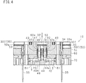
- FIG. 4 is a sectional view taken along line 4-4 of FIG. 3 .
- the second electromagnetic coil 50C (50) is attached to the support plate 60 through an insulating member 51.
- the support plate 60 is formed into a rectangular shape from a non-magnetic insulating material such as alumina.
- the support plate 60 has spacers 60a protruding in the direction of the axis Z.
- the support plate 60 is attached to the bed 70.
- the bed 70 is formed into a rectangular shape from metal such as stainless steel or aluminum.
- a cylindrical second inlet pipe 42 is connected to an inlet 41 of the flow path of the cooling plate 40.
- the second inlet pipe 42 extends through the space 52 of the second electromagnetic coil 50C to a region outside the second electromagnetic coil 50C.
- a cylindrical second outlet pipe 47 is connected to an outlet 46 of the flow path of the cooling plate 40.
- the second outlet pipe 47 extends through the space 52 of the second electromagnetic coil 50C to the region outside the second electromagnetic coil 50C. That is, the second inlet pipe 42 and the second outlet pipe 47 are connected to the inlet 41 and the outlet 46, respectively, within the same space 52 of the second electromagnetic coil 50C.
- junction pipes 44 and 49 are connected to the outer circumferences of end portions 42a and 47a, located opposite the cooling plate 40, of the pipes 42 and 47, respectively, by means of respective first members 43.
- the first seal member 43 is an O-ring formed of resin or the like.
- the junction pipes 44 and 49 are formed into a cylindrical shape from metal such as stainless steel. Thus, the pipes 42 and 47 and the junction pipes 44 and 49 are radially sealed respectively by means of the respective first seal members 43.
- the junction pipes 44 and 49 are supported, by the bed 70 through respective second seal members 61, at the outer circumferences of end portions 44a and 49a located opposite the cooling plate 40.
- the second seal member 61 is an O-ring formed of resin or the like.
- the bed 70 has flow paths 72 and 73 for cooling water internally formed.
- the flow paths 72 and 73 have a circular cross section.
- the junction pipe 44 is connected to the flow path 72, and the junction pipe 49 is connected to the flow path 73.
- the flow paths 72 and 73 and the junction pipes 44 and 49 are radially sealed respectively by means of the respective second seal members 61.
- Electric wires 35 and 55 are connected to electrode pins 34 and 53, respectively.
- the electric wires 35 and 55 extend in the direction of the axis Z through the support plate 60 and through the bed 70 to a region outside the bed 70.
- the second electromagnetic coil 50C (50), the cooling plate 40, the second inlet pipe 42, the second outlet pipe 47, the junction pipes 44 and 49, and the flow paths 72 and 73 constitute a cooling structure for the second electromagnetic coil 50C (50).
- FIG. 5 is a plan view of the coil unit 10, and FIG. 6 is a sectional view taken along line 6-6 of FIG. 5 .
- a cylindrical first inlet pipe 22 is connected to an inlet 21 of a flow path of the constant-temperature plate 20.
- the first inlet pipe 22 extends through the space 32 of the first electromagnetic coil 30A, through the cooling plate 40, and through the space 52 of the second electromagnetic coil 50A to a region outside the second electromagnetic coil 50A.
- a cylindrical first outlet pipe 27 is connected to an outlet 26 of the flow path of the constant-temperature plate 20.
- the first outlet pipe 27 extends through the space 32 of the first electromagnetic coil 30A, through the cooling plate 40, and through the space 52 of the second electromagnetic coil 50A to the region outside the second electromagnetic coil 50A. That is, the first inlet pipe 22 and the first outlet pipe 27 are connected to the inlet 21 and the outlet 26, respectively, within the same space 32 of the first electromagnetic coil 30A.
- junction pipes 24 and 29 are connected to the outer circumferences of end portions 22a and 27a, located opposite the constant-temperature plate 20, of the pipes 22 and 27, respectively, by means of the respective first seal members 43.
- the junction pipes 24 and 29 are formed into a cylindrical shape from metal such as stainless steel.
- the pipes 22 and 27 and the junction pipes 24 and 29 are radially sealed respectively by means of the respective first seal members 43.
- the junction pipes 24 and 29 are supported, by the bed 70 through the respective second seal members 61, at the outer circumferences of end portions 24a and 29a thereof located opposite the constant-temperature plate 20.
- the bed 70 has flow paths 76 and 77 for cooling water internally formed.
- the flow paths 76 and 77 have a circular cross section.
- the junction pipe 24 is connected to the flow path 76, and the junction pipe 29 is connected to the flow path 77.
- the flow paths 76 and 77 and the junction pipes 24 and 29 are radially sealed respectively by means of the respective second seal members 61.
- the electric wires 35 and 55 are connected to the electrode pins 34 and 53, respectively.
- the electric wires 35 and 55 extend in the direction of the axis Z through the support plate 60 and through the bed 70 to the region outside the bed 70.
- the first electromagnetic coil 30A (30), the constant-temperature plate 20, the first inlet pipe 22, the first outlet pipe 27, the junction pipes 24 and 29, and the flow paths 76 and 77 constitute a cooling structure for the first electromagnetic coil 30A (30).
- FIG. 7 is an exploded view of the cooling plate 40
- FIG. 8 is a perspective view of the cooling plate 40 before attachment of an upper plate.
- the cooling plate 40 includes an upper plate 40a, a middle plate 40b, and a lower plate 40c.
- the upper plate 40a, the middle plate 40b, and the lower plate 40c have respective rectangular plate-like shapes of the same size.
- the upper plate 40a, the middle plate 40b, and the lower plate 40c have through holes 40d internally formed for receiving the respective spacers 60a of the support plate 60.
- the upper plate 40a, the middle plate 40b, and the lower plate 40c have through holes 40e internally formed for allowing the pipes 22 and 27 to extend through the plates respectively.
- the through holes 40e are formed at positions corresponding to the space 52 of the second electromagnetic coil 50A.
- the middle plate 40b has a meandering through hole 40f internally formed for partially defining a flow path 40g of the cooling plate 40.
- the upper plate 40a and the lower plate 40c are united together with the middle plate 40b held therebetween, thereby forming the flow path 40g of the cooling plate 40.
- the lower plate 40c has the inlet 41 and the outlet 46 of the flow path 40g internally formed.
- the inlet 41 and the outlet 46 are formed at positions corresponding to the space 52 of the second electromagnetic coil 50C.
- FIG. 9 is an exploded view of the constant-temperature plate 20, and FIG. 10 is a perspective view of the constant-temperature plate 20 as viewed before attachment of an upper plate.
- the constant-temperature plate 20 includes an upper plate 20a, a middle plate 20b, and a lower plate 20c.
- the upper plate 20a, the middle plate 20b, and the lower plate 20c have respective rectangular plate-like shapes of the same size.
- the middle plate 20b has a meandering through hole 20f internally formed for partially defining a flow path 20g of the constant-temperature plate 20.
- the upper plate 20a and the lower plate 20c are united together with the middle plate 20b held therebetween, thereby forming the flow path 20g of the constant-temperature plate 20.
- the lower plate 20c has the inlet 21 and the outlet 26 of the flow path 20g internally formed. The inlet 21 and the outlet 26 are formed at positions corresponding to the space 32 of the first electromagnetic coil 30A.
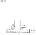
- FIG. 11 is a sectional view showing the structure of connection of the first inlet pipe 22.
- the pipes 22, 27, 42, and 47 are formed of titanium and have similar respective structures of connection.
- the structure of connection of the first inlet pipe 22 is described by way of example.
- the lower plate 20c of the constant-temperature plate 20 has a metal layer 23 formed through diffusion of a metal material in a region around the inlet 21 of the flow path 20g.
- the metal layer 23 is formed of silver, copper and titanium.
- the end portion 22a of the first inlet pipe 22 has a flange 22b formed thereat.
- the flange 22b of the first inlet pipe 22 is brought into contact with the metal layer 23; then, the metal layer 23 and the first pipe 22 are connected by means of silver solder 25. That is, the first inlet pipe 22 is connected to the constant-temperature plate 20 by means of the metal layer 23 by means of the silver solder 25.
- FIG. 12 is a schematic view showing an XY linear actuator 11.
- the XY linear actuator 11 electromagnettic actuator
- the XY linear actuator 11 includes a plurality of coil units 10 disposed in a two-dimensional manner.
- the plurality of coil units 10 are disposed such that the mutually adjacent coil units 10 are oriented 90° different from each other.
- FIG. 12 shows the coil units 10 with their constant-temperature plates 20 removed.
- the XY linear actuator 11 has a table 12 disposed opposite the electromagnetic coils 30 and 50 with respect to the constant-temperature plates 20.
- the table 12 (driven member) is formed into a rectangular plate-like shape and has a magnet internally incorporated.
- a wafer W is attached on the table 12.
- the table 12 is two-dimensionally driven along the constant-temperature plates 20 in response to magnetic fluxes generated in the electromagnetic coils 30 and 50.
- 10 coil unit; 11: XY linear actuator (electromagnetic actuator); 12: table (driven member); 20: constant-temperature plate (first cooling member); 20g: flow path; 21: inlet; 22: first inlet pipe; 22a: end portion; 23: metal layer; 24: junction pipe; 24a: end portion; 25: silver solder; 26: outlet; 27: first outlet pipe; 27a: end portion; 29: junction pipe; 29a: end portion; 30: first electromagnetic coil; 30e: end surface; 30f: end surface; 31: conductor winding; 32: space; 40: cooling plate (second cooling member); 40g: flow path; 41: inlet; 42: second inlet pipe; 42a: end portion; 43: first seal member; 44: junction pipe; 44a: end portion; 46: outlet; 47: second outlet pipe; 47a: end portion; 49: junction pipe; 49a: end portion; 50: second electromagnetic coil; 50g: end surface; 52: space; 60: support plate; 61: second seal member; and 70: bed.
Landscapes
- Engineering & Computer Science (AREA)
- Power Engineering (AREA)
- Physics & Mathematics (AREA)
- Electromagnetism (AREA)
- Chemical & Material Sciences (AREA)
- Combustion & Propulsion (AREA)
- Motor Or Generator Cooling System (AREA)
- Electromagnets (AREA)
- Transformer Cooling (AREA)
- Exposure Of Semiconductors, Excluding Electron Or Ion Beam Exposure (AREA)
- Exposure And Positioning Against Photoresist Photosensitive Materials (AREA)
- Container, Conveyance, Adherence, Positioning, Of Wafer (AREA)
Description
- The present invention relates to a structure for cooling an electromagnetic coil for use in an electromagnetic actuator, etc.
- In a cooling structure for such an electromagnetic coil, a plate-like cooling element is attached to an end surface, with respect to the direction of a center axis, of the electromagnetic coil (refer to Patent Document 1). According to
Patent Document 1, an inlet pipe and an outlet pipe for coolant are connected to a cooling element at radially opposite end portions of an electromagnetic coil. - Patent Document 1:
Japanese Patent No. 4022181 - The cooling structure described in
Patent Document 1 may potentially involve the following problem: in the case where a plurality of electromagnetic coils to which the respective cooling elements are attached are to be disposed in parallel, the inlet pipes and the outlet pipes interfere with one another. Thus, difficulty is encountered in forming a unit in which a plurality of electromagnetic coils are disposed in parallel, or further in disposing the units in parallel. - The present invention has been conceived to solve the problem, and a primary object of the invention is to provide such a structure for cooling an end surface, with respect to an axial direction, of an electromagnetic coil that enables a plurality of the electromagnetic coils to be arbitrarily disposed in parallel.
- Means for solving the above problem, and operation and effects of the means will next be described.
- First means provides a cooling structure for an electromagnetic coil comprises an electromagnetic coil which has a space extending in a direction of a predetermined axis; a cooling member attached to an end surface, with respect to the direction of the predetermined axis, of the electromagnetic coil and having a flow path for fluid internally formed; and an inlet pipe and an outlet pipe connected, within the space, to an inlet and outlet, respectively, of the flow path of the cooling member and extending through the space to a region outside the electromagnetic coil.
- According to the above configuration, the electromagnetic coil has the space extending in the direction of the predetermined axis. Furthermore, the cooling member is attached to the end surface, with respect to the direction of the predetermined axis, of the electromagnetic coil, and the cooling member has the flow path for fluid internally formed.
- Within the above-mentioned space, the inlet pipe and the outlet pipe are connected to the inlet and outlet, respectively, of the flow path of the cooling member. The inlet pipe and the outlet pipe extend through the space to the region outside the electromagnetic coil. Thus, by utilization of the space formed inside the electromagnetic coil, the inlet pipe and the outlet pipe are connected to the inlet and the outlet, respectively, of the flow path of the cooling member, whereby fluid can be flowed through the flow path. Therefore, a plurality of the electromagnetic coils can be arbitrarily disposed in parallel without involvement of mutual interference of the pipes of the electromagnetic coils.
- Second means provides a cooling structure for an electromagnetic coil comprises a plurality of electromagnetic coils each of which has a space extending in a direction of a predetermined axis and are disposed with their predetermined axes juxtaposed in parallel; a cooling member attached to end surfaces, with respect to the direction of the predetermined axes, of the plurality of electromagnetic coils and having a flow path for fluid internally formed; an inlet pipe connected, within the space of any one of the electromagnetic coils, to an inlet of the flow path of the cooling member and extending through the space to a region outside the electromagnetic coil; and an outlet pipe connected, within the space of any one of the electromagnetic coils, to an outlet of the flow path of the cooling member and extending through the space to a region outside the electromagnetic coil.
- According to the above configuration, a plurality of the electromagnetic coils are disposed with their predetermined axes juxtaposed in parallel, and the cooling member is attached to the end surfaces, with respect to the direction of the predetermined axes, of the electromagnetic coils. Furthermore, the inlet pipe is connected, within the space of any one of the electromagnetic coils, to the inlet of the flow path of the cooling member, and the outlet pipe is connected, within the space of any one of the electromagnetic coils, to the outlet of the flow path of the cooling member. Thus, by flowing fluid through the flow path of the cooling member, the plurality of electromagnetic coils can be cooled.
- In the third means, the inlet pipe and the outlet pipe are connected to the inlet and the outlet, respectively, within the same space of the electromagnetic coil.
- According to the above configuration, the plurality of electromagnetic coils disposed with their predetermined axes juxtaposed in parallel employ a constitution similar to that of the first means, whereby the inlet pipe and the outlet pipe can be disposed within a single electromagnetic coil.
- Fourth means provides a cooling structure for an electromagnetic coil comprises a first electromagnetic coil and a second electromagnetic coil each of which has a space extending in a direction of a predetermined axis and which are aligned with the direction of the predetermined axis; a first cooling member attached to an end surface, located opposite the second electromagnetic coil with respect to the direction of the predetermined axis, of the first electromagnetic coil and having a flow path for fluid internally formed; a second cooling member attached to an end surface, located toward the second electromagnetic coil with respect to the direction of the predetermined axis, of the first electromagnetic coil and to an end surface, located toward the first electromagnetic coil with respect to the direction of the predetermined axis, of the second electromagnetic coil and having a flow path for fluid internally formed ; and a first inlet pipe and a first outlet pipe connected, within the space of the first electromagnetic coil, to an inlet and an outlet, respectively, of the flow path of the first cooling member and extending through the space of the first electromagnetic coil, through the second cooling member, and through the space of the second electromagnetic coil to a region outside the second electromagnetic coil.
- According to the above configuration, the cooling structure comprises the first electromagnetic coil and the second electromagnetic coil each of which has the space extending in the direction of the predetermined axis and which are aligned in the direction of the predetermined axis. In addition to the first cooling member corresponding to the cooling member of the first means, the second cooling member is provided between the first electromagnetic coil and the second electromagnetic coil. Furthermore, by utilization of the inside spaces of the first and second electromagnetic coils, the first inlet pipe and the first outlet pipe can be connected to the inlet and the outlet, respectively, of the flow path of the first cooling member while extending through the second cooling member. Thus, even in the case of a configuration in which the first electromagnetic coil and the second electromagnetic coil are aligned in the direction of the predetermined axis, a plurality of groups each consisting of the first electromagnetic coil and the second electromagnetic coil can be arbitrarily disposed in parallel.
- In the fifth means, the cooling structure further comprises a second inlet pipe and a second outlet pipe connected, within the space of the second electromagnetic coil, to an inlet and an outlet, respectively, of the second cooling member and extending through the space of the second electromagnetic coil to a region outside the second electromagnetic coil.
- According to the above configuration, even in a configuration in which the first electromagnetic coil and the second electromagnetic coil are aligned with the direction of the predetermined axis, fluid can be flowed to the first cooling member and to the second cooling member.
- Sixth means provides a cooling structure for an electromagnetic coil comprises a plurality of first electromagnetic coils each of which has a space extending in a direction of a predetermined axis and which are disposed with their predetermined axes juxtaposed in parallel; a plurality of second electromagnetic coils each of which has a space extending in the direction of the predetermined axis and which are aligned with the respective first electromagnetic coils in the direction of the predetermined axes; a first cooling member attached to end surfaces, with respect to the direction of the predetermined axes, of the plurality of first electromagnetic coils and having a flow path for fluid internally formed; a second cooling member attached to end surfaces, located toward the second electromagnetic coils with respect to the direction of the predetermined axes, of the plurality of first electromagnetic coils and to end surfaces, located toward the first electromagnetic coils with respect to the direction of the predetermined axes, of the plurality of second electromagnetic coils and having a flow path for fluid internally formed; a first inlet pipe connected, within the space of any one of the first electromagnetic coils, to an inlet of the flow path of the first cooling member and extending through the space of the first electromagnetic coil, through the second cooling member, and through the space of the second electromagnetic coil to a region outside the second electromagnetic coil; and a first outlet pipe connected, within the space of any one of the first electromagnetic coils, to an outlet of the flow path of the first cooling member and extending through the space of the first electromagnetic coil, through the second cooling member, and through the space of the second electromagnetic coil to a region outside the second electromagnetic coil.
- The above configuration includes those of the second and fourth means and thus can yield actions and effects of the second and fourth means.
- In seventh means, the first inlet pipe and the first outlet pipe are connected to the inlet and the outlet, respectively, within the same space of the first electromagnetic coil.
- According to the above configuration, similar to the third means, the first inlet pipe and the first outlet pipe can be disposed within a single first electromagnetic coil.
- In eighth means, the cooling structure for an electromagnetic coil further comprises a second inlet pipe connected, within the space of any one of the plurality of second electromagnetic coils, to an inlet of the flow path of the second cooling member and extending through the space of the second electromagnetic coil to a region outside the second electromagnetic coil, and a second outlet pipe connected, within the space of any one of the plurality of second electromagnetic coils, to an outlet of the flow path of the second cooling member and extending through the space of the second electromagnetic coil to a region outside the second electromagnetic coil.
- According to the above configuration, even in a configuration in which a plurality of the first electromagnetic coils are disposed with their predetermined axes juxtaposed in parallel, and the first electromagnetic coils and the second electromagnetic coils are aligned in the direction of the predetermined axes, fluid can be flowed to the first cooling member and to the second cooling member.
- In ninth means, the second inlet pipe and the second outlet pipe are connected to the inlet and the outlet, respectively, within the same space of the second electromagnetic coil.
- According to the above configuration, similar to the third means, the second inlet pipe and the second outlet pipe can be disposed within a single second electromagnetic coil.
- In tenth means, a junction pipe is connected, by means of a first seal member, to an outer circumference of an end portion, located opposite the cooling member, of the pipe, and the junction pipe is supported, by means of a second seal member, at an outer circumference of an end portion thereof located opposite the cooling member.
- According to the above configuration, the junction pipe is connected, by means of the first seal member, to the outer circumference of an end portion, located opposite the cooling member, of the pipe. Also, the junction pipe is supported, by means of the second member, at the outer circumference of an end portion thereof located opposite the cooling member. Thus, force imposed on the pipe can be mitigated by the first seal member, the junction pipe and the second seal member, thereby restraining imposition of load on a connection between the cooling member and the pipe. Furthermore, since the first seal member and the second seal member allow some movement of the pipe and the junction pipe, errors in connecting the pipe and in connecting the junction pipe can be absorbed.
- In eleventh means, the cooling member is formed of alumina; the pipe is formed of titanium; and the pipe is connected to the cooling member by silver-soldering by means of a metal layer diffusion-formed on a surface of the cooling member.
- According to the above configuration, since alumina and titanium are non-magnetic materials, the cooling member and the pipe can be restrained from affecting magnetic fluxes generated in the electromagnetic coils. Furthermore, the metal layer diffusion-formed on the surface of the cooling member allows the pipe of titanium to be connected to the cooling member of alumina by use of silver solder.
- In twelfth means, the electromagnetic coil comprises a conductor winding formed by winding a strip conductor by a plurality of turns around the predetermined axis, and the cooling member is attached to an end surface, with respect to the direction of the predetermined axis, of the conductor winding.
- According to the above configuration, the electromagnetic coil comprises a conductor winding formed by winding a strip conductor by a plurality of turns around the predetermined axis. Also, the cooling member is attached to an end surface, with respect to the direction of the predetermined axis, of the conductor winding. Thus, the conductor winding can transmit heat, along the entire length in the axial direction, from its end surface to the cooling member, whereby the cooling efficiency of the conductor winding can be improved.
- Thirteenth means provides an electromagnetic actuator comprises the cooling structure for an electromagnetic coil according to any one of the first to twelfth means.
- According to the above configuration, the electromagnetic actuator can yield actions and effects similar to those yielded by the above means.
- In fourteenth means, the electromagnetic actuator further comprises a driven member which is disposed opposite the electromagnetic coils with respect to the cooling members and is two-dimensionally driven along the cooling members in response to magnetic fluxes generated in the electromagnetic coils.
- According to the above configuration, the electromagnetic actuator further comprises the driven member which is disposed opposite the electromagnetic coils with respect to the cooling members and is two-dimensionally driven along the cooling members in response to magnetic fluxes generated in the electromagnetic coils. Thus, the inlet pipes and the outlet pipes for flowing fluid through the corresponding cooling members cannot be connected to the cooling members at any side positions thereof and at any positions located opposite the electromagnetic coils. In this connection, because of employment of the cooling structure for an electromagnetic coil according to any one of the first to twelfth means, even such an electromagnetic actuator allows fluid to flow through the cooling members.
-
- [
FIG. 1 ] Perspective view of a coil unit. - [
FIG. 2 ] Perspective view of the coil unit as viewed before attachment of a constant-temperature plate. - [
FIG. 3 ] Plan view of the coil unit as viewed before attachment of the constant-temperature plate. - [
FIG. 4 ] Sectional view taken along line 4-4 ofFIG. 3 . - [
FIG. 5 ] Plan view of the coil unit. - [
FIG. 6 ] Sectional view taken along line 6-6 ofFIG. 5 . - [
FIG. 7 ] Exploded view of a cooling plate. - [
FIG. 8 ] Perspective view of the cooling plate as viewed before attachment of an upper plate. - [
FIG. 9 ] Exploded view of the constant-temperature plate. - [
FIG. 10 ] Perspective view of the constant-temperature plate as viewed before attachment of the upper plate. - [
FIG. 11 ] Sectional view showing the structure of connection of a first inlet pipe. - [
FIG. 12 ] Schematic view showing an XY linear actuator. - An embodiment of the present invention will next be described with reference to the drawings. The present embodiment is of an XY linear actuator for use in a lithographic apparatus (stepper) or the like.
- As shown in
FIGS. 1 and2 , acoil unit 10, which is a component of the XY linear actuator, includes a constant-temperature plate 20, first electromagnetic coils 30 (30A, 30B, 30C), a coolingplate 40, second electromagnetic coils 50 (50A, 50B, 50C), asupport plate 60, and abed 70. Thecoil unit 10 as a whole has the form of a rectangular parallelepiped. -
FIG. 3 is a plan view of thecoil unit 10 as viewed before attachment of the constant-temperature plate 20. Referring toFIG. 3 , the firstelectromagnetic coil 30 includes a conductor winding 31 formed by winding a strip (film) conductor by a plurality of turns around an axis Z (predetermined axis). One end of the strip conductor is connected to anelectrode pin 33, and the other end of the strip conductor is connected to anelectrode pin 34. The conductor winding 31 has the form of an elongated cylinder (cylinder). Aspace 32 extending in the direction of the axis Z is formed inside the conductor winding 31 (first electromagnetic coil 30). The conductor winding 31 is wound such that the strip conductor and a bond layer alternatingly overlap each other while the strip conductor layers are bonded by means of the intervening bond layer. The bond layer is formed of an electrically insulating material. The strip conductor layers can be electrically insulated from each other by means of an insulating layer rather than bonded by means of the bond layer. - The first
electromagnetic coils electromagnetic coils FIG. 3 ). - The constant-
temperature plate 20 is attached to end surfaces, located opposite the secondelectromagnetic coils 50 with respect to the direction of the axes Z, of the firstelectromagnetic coils 30; specifically, to endsurfaces 30e of the firstelectromagnetic coils 30. The constant-temperature plate 20 (first cooling member) is formed into a rectangular shape from a non-magnetic insulating material such as alumina. The constant-temperature plate 20 has a flow path for cooling water (fluid) internally formed. - The cooling
plate 40 is attached to end surfaces, located toward the secondelectromagnetic coils 50 with respect to the direction of the axes Z, of the firstelectromagnetic coils 30; specifically, to endsurfaces 30f of the firstelectromagnetic coils 30. The cooling plate 40 (second cooling member) is formed into a rectangular shape from a non-magnetic insulating material such as alumina. The secondelectromagnetic coils 50 are attached to the surface, located opposite the firstelectromagnetic coils 30, of the coolingplate 40. That is, the coolingplate 40 is attached to end surfaces, located toward the firstelectromagnetic coils 30, of the secondelectromagnetic coils 50; specifically, to endsurfaces 50g of the second electromagnetic coils 50 (seeFIG. 4 ). The coolingplate 40 has a flow path for cooling water (fluid) internally formed. - The second
electromagnetic coil 50 has the same structure as that of the firstelectromagnetic coil 30. The firstelectromagnetic coils 30 and the secondelectromagnetic coils 50 are aligned in the direction of the axes Z. Specifically, the firstelectromagnetic coil 30A and the secondelectromagnetic coil 50A are aligned in the direction of the axis Z; the firstelectromagnetic coil 30B and the secondelectromagnetic coil 50B are aligned in the direction of the axis Z; and the firstelectromagnetic coil 30C and the secondelectromagnetic coil 50C are aligned in the direction of the axis Z. -
FIG. 4 is a sectional view taken along line 4-4 ofFIG. 3 . As shown inFIG. 4 , the secondelectromagnetic coil 50C (50) is attached to thesupport plate 60 through an insulatingmember 51. Thesupport plate 60 is formed into a rectangular shape from a non-magnetic insulating material such as alumina. Thesupport plate 60 has spacers 60a protruding in the direction of the axis Z. Thesupport plate 60 is attached to thebed 70. Thebed 70 is formed into a rectangular shape from metal such as stainless steel or aluminum. - Within a
space 52 of the secondelectromagnetic coil 50C (50), a cylindricalsecond inlet pipe 42 is connected to aninlet 41 of the flow path of the coolingplate 40. Thesecond inlet pipe 42 extends through thespace 52 of the secondelectromagnetic coil 50C to a region outside the secondelectromagnetic coil 50C. Also, within thespace 52 of the secondelectromagnetic coil 50C (50), a cylindricalsecond outlet pipe 47 is connected to anoutlet 46 of the flow path of the coolingplate 40. Thesecond outlet pipe 47 extends through thespace 52 of the secondelectromagnetic coil 50C to the region outside the secondelectromagnetic coil 50C. That is, thesecond inlet pipe 42 and thesecond outlet pipe 47 are connected to theinlet 41 and theoutlet 46, respectively, within thesame space 52 of the secondelectromagnetic coil 50C. -
Junction pipes end portions 42a and 47a, located opposite the coolingplate 40, of thepipes first members 43. Thefirst seal member 43 is an O-ring formed of resin or the like. Thejunction pipes pipes junction pipes first seal members 43. - The
junction pipes bed 70 through respectivesecond seal members 61, at the outer circumferences of end portions 44a and 49a located opposite the coolingplate 40. Thesecond seal member 61 is an O-ring formed of resin or the like. Thebed 70 hasflow paths flow paths junction pipe 44 is connected to theflow path 72, and thejunction pipe 49 is connected to theflow path 73. Theflow paths junction pipes second seal members 61. -
Electric wires pins electric wires support plate 60 and through thebed 70 to a region outside thebed 70. - The second
electromagnetic coil 50C (50), the coolingplate 40, thesecond inlet pipe 42, thesecond outlet pipe 47, thejunction pipes flow paths electromagnetic coil 50C (50). -
FIG. 5 is a plan view of thecoil unit 10, andFIG. 6 is a sectional view taken along line 6-6 ofFIG. 5 . As shown inFIG. 5 , within thespace 32 of the firstelectromagnetic coil 30A (30), a cylindricalfirst inlet pipe 22 is connected to aninlet 21 of a flow path of the constant-temperature plate 20. Thefirst inlet pipe 22 extends through thespace 32 of the firstelectromagnetic coil 30A, through the coolingplate 40, and through thespace 52 of the secondelectromagnetic coil 50A to a region outside the secondelectromagnetic coil 50A. Also, within thespace 32 of the firstelectromagnetic coil 30A (30), a cylindricalfirst outlet pipe 27 is connected to anoutlet 26 of the flow path of the constant-temperature plate 20. Thefirst outlet pipe 27 extends through thespace 32 of the firstelectromagnetic coil 30A, through the coolingplate 40, and through thespace 52 of the secondelectromagnetic coil 50A to the region outside the secondelectromagnetic coil 50A. That is, thefirst inlet pipe 22 and thefirst outlet pipe 27 are connected to theinlet 21 and theoutlet 26, respectively, within thesame space 32 of the firstelectromagnetic coil 30A. -
Junction pipes end portions 22a and 27a, located opposite the constant-temperature plate 20, of thepipes first seal members 43. Thejunction pipes pipes junction pipes first seal members 43. - The
junction pipes bed 70 through the respectivesecond seal members 61, at the outer circumferences ofend portions 24a and 29a thereof located opposite the constant-temperature plate 20. Thebed 70 hasflow paths flow paths junction pipe 24 is connected to theflow path 76, and thejunction pipe 29 is connected to theflow path 77. Theflow paths junction pipes second seal members 61. - The
electric wires electric wires support plate 60 and through thebed 70 to the region outside thebed 70. - The first
electromagnetic coil 30A (30), the constant-temperature plate 20, thefirst inlet pipe 22, thefirst outlet pipe 27, thejunction pipes flow paths electromagnetic coil 30A (30). -
FIG. 7 is an exploded view of the coolingplate 40, andFIG. 8 is a perspective view of the coolingplate 40 before attachment of an upper plate. As shown inFIG. 7 , the coolingplate 40 includes an upper plate 40a, amiddle plate 40b, and alower plate 40c. - The upper plate 40a, the
middle plate 40b, and thelower plate 40c have respective rectangular plate-like shapes of the same size. The upper plate 40a, themiddle plate 40b, and thelower plate 40c have through holes 40d internally formed for receiving the respective spacers 60a of thesupport plate 60. The upper plate 40a, themiddle plate 40b, and thelower plate 40c have through holes 40e internally formed for allowing thepipes space 52 of the secondelectromagnetic coil 50A. - The
middle plate 40b has a meandering throughhole 40f internally formed for partially defining aflow path 40g of the coolingplate 40. The upper plate 40a and thelower plate 40c are united together with themiddle plate 40b held therebetween, thereby forming theflow path 40g of the coolingplate 40. Thelower plate 40c has theinlet 41 and theoutlet 46 of theflow path 40g internally formed. Theinlet 41 and theoutlet 46 are formed at positions corresponding to thespace 52 of the secondelectromagnetic coil 50C. -
FIG. 9 is an exploded view of the constant-temperature plate 20, andFIG. 10 is a perspective view of the constant-temperature plate 20 as viewed before attachment of an upper plate. As shown inFIG. 9 , the constant-temperature plate 20 includes an upper plate 20a, amiddle plate 20b, and alower plate 20c. - The upper plate 20a, the
middle plate 20b, and thelower plate 20c have respective rectangular plate-like shapes of the same size. - The
middle plate 20b has a meandering throughhole 20f internally formed for partially defining aflow path 20g of the constant-temperature plate 20. The upper plate 20a and thelower plate 20c are united together with themiddle plate 20b held therebetween, thereby forming theflow path 20g of the constant-temperature plate 20. Thelower plate 20c has theinlet 21 and theoutlet 26 of theflow path 20g internally formed. Theinlet 21 and theoutlet 26 are formed at positions corresponding to thespace 32 of the firstelectromagnetic coil 30A. -
FIG. 11 is a sectional view showing the structure of connection of thefirst inlet pipe 22. Thepipes first inlet pipe 22 is described by way of example. - The
lower plate 20c of the constant-temperature plate 20 has ametal layer 23 formed through diffusion of a metal material in a region around theinlet 21 of theflow path 20g. Themetal layer 23 is formed of silver, copper and titanium. Theend portion 22a of thefirst inlet pipe 22 has a flange 22b formed thereat. The flange 22b of thefirst inlet pipe 22 is brought into contact with themetal layer 23; then, themetal layer 23 and thefirst pipe 22 are connected by means ofsilver solder 25. That is, thefirst inlet pipe 22 is connected to the constant-temperature plate 20 by means of themetal layer 23 by means of thesilver solder 25. -
FIG. 12 is a schematic view showing an XY linear actuator 11. As shown inFIG. 12 , the XY linear actuator 11 (electromagnetic actuator) includes a plurality ofcoil units 10 disposed in a two-dimensional manner. The plurality ofcoil units 10 are disposed such that the mutuallyadjacent coil units 10 are oriented 90° different from each other.FIG. 12 shows thecoil units 10 with their constant-temperature plates 20 removed. - The XY linear actuator 11 has a table 12 disposed opposite the
electromagnetic coils temperature plates 20. The table 12 (driven member) is formed into a rectangular plate-like shape and has a magnet internally incorporated. A wafer W is attached on the table 12. The table 12 is two-dimensionally driven along the constant-temperature plates 20 in response to magnetic fluxes generated in theelectromagnetic coils - The present embodiment described in detail above has the following advantages.
- Within the
space 32 of the firstelectromagnetic coil 30A, thefirst inlet pipe 22 and thefirst outlet pipe 27 are connected to theinlet 21 and theoutlet 26, respectively, of theflow path 20g of the constant-temperature plate 20. Also, thefirst inlet pipe 22 and thefirst outlet pipe 27 extend through thespace 32 to a region outside the firstelectromagnetic coil 30A. Thus, by utilization of thespace 32 formed inside the firstelectromagnetic coil 30A, thefirst inlet pipe 22 and thefirst outlet pipe 27 are connected to theinlet 21 and theoutlet 26, respectively, of theflow path 20g of the constant-temperature plate 20, whereby cooling water can be flowed through theflow path 20g. Therefore, a plurality of the firstelectromagnetic coils 30 can be arbitrarily disposed in parallel without involvement of mutual interference of the pipes of the firstelectromagnetic coils 30. - A plurality of the first
electromagnetic coils 30 are disposed with their axes Z juxtaposed in parallel, and the constant-temperature plate 20 is attached to the end surfaces 30e, with respect to the direction of the axes Z, of the firstelectromagnetic coils 30. Furthermore, thefirst inlet pipe 22 is connected, within thespace 32 of the firstelectromagnetic coil 30A among the firstelectromagnetic coils 30, to thefirst inlet 21 of theflow path 20g of the constant-temperature plate 20, and thefirst outlet pipe 27 is connected, within thespace 32 of the firstelectromagnetic coil 30A, to theoutlet 26 of theflow path 20g of the constant-temperature plate 20. Thus, by flowing fluid through theflow path 20g of the constant-temperature plate 20, the plurality of firstelectromagnetic coils 30 can be cooled. - The
first inlet pipe 22 and thefirst outlet pipe 27 are connected to theinlet 21 and theoutlet 26, respectively, within thesame space 32 of the firstelectromagnetic coil 30A. Thus, thefirst inlet pipe 22 and thefirst outlet pipe 27 can be disposed within the single firstelectromagnetic coil 30A among the plurality of firstelectromagnetic coils 30 disposed with their axes Z juxtaposed in parallel. - The first
electromagnetic coil 30 and the secondelectromagnetic coil 50 having therespective spaces temperature plate 20, the coolingplate 40 is provided between the firstelectromagnetic coil 30 and the secondelectromagnetic coil 50. Furthermore, by utilization of theinside spaces electromagnetic coil 30 and the secondelectromagnetic coil 50, thefirst inlet pipe 22 and thefirst outlet pipe 27 can be connected to theinlet 21 and theoutlet 26, respectively, of theflow path 20g of the constant-temperature plate 20 while extending through the coolingplate 40. Thus, even in the case of a configuration in which the firstelectromagnetic coil 30 and the secondelectromagnetic coil 50 are aligned in the direction of the axis Z, a plurality of groups each consisting of the firstelectromagnetic coil 30 and the secondelectromagnetic coil 50 can be arbitrarily disposed in parallel. - The present embodiment includes the
second inlet pipe 42 and thesecond outlet pipe 47 connected, within thespace 52 of the secondelectromagnetic coil 50C, to theinlet 41 and theoutlet 46, respectively, of theflow path 40g of the coolingplate 40 and extending through thespace 52 of the secondelectromagnetic coil 50C to the region outside the secondelectromagnetic coil 50C. Thus, even in a configuration in which the firstelectromagnetic coil 30C and the secondelectromagnetic coil 50C are aligned in the direction of the axis Z, cooling water can be flowed to the constant-temperature plate 20 and to thecooling plate 40. - Even in a configuration in which a plurality of the first
electromagnetic coils 30 are disposed with their axes Z juxtaposed in parallel, and the firstelectromagnetic coils 30 and the secondelectromagnetic coils 50 are aligned in the direction of the axes Z, cooling water can be flowed to the constant-temperature-plate 20 and to thecooling plate 40. - The
junction pipe 24 is connected, by means of thefirst seal member 43, to the outer circumference of theend portion 22a, located opposite the constant-temperature plate 20, of thefirst inlet pipe 22. Also, thejunction pipe 24 is supported, by thebed 70 through thesecond seal member 61, at the outer circumference of theend portion 24a thereof located opposite the constant-temperature plate 20. Thus, force imposed on thefirst inlet pipe 22 can be mitigated by thefirst seal member 43, thejunction pipe 24 and thesecond seal member 61, thereby restraining imposition of load on the connection between the constant-temperature plate 20 and thefirst inlet pipe 22. Furthermore, since thefirst seal member 43 and thesecond seal member 61 allow some movement of thefirst inlet pipe 22 and thejunction pipe 24, errors in connecting thefirst inlet pipe 22 and in connecting thejunction pipe 24 can be absorbed. Similar effects can also be yielded in the case of thefirst outlet pipe 27, thesecond inlet pipe 42 and thesecond outlet pipe 47. - The constant-
temperature plate 20 is formed of alumina, and the first inlet pipe 22 (first outlet pipe 27) is formed of titanium. Since alumina and titanium are non-magnetic materials, the constant-temperature plate 20 and the first inlet pipe 22 (first outlet pipe 27) can be restrained from affecting magnetic fluxes generated in the electromagnetic coils. Furthermore, themetal layer 23 diffusion-formed on the surface of the constant-temperature plate 20 allows the first inlet pipe 22 (first outlet pipe 27) of titanium to be connected to the constant-temperature plate 20 of alumina by means of thesilver solder 25. Similar effects can also be yielded in the case of the coolingplate 40 and the second inlet pipe 42 (second outlet pipe 47). - The first
electromagnetic coil 30 includes a conductor winding 31 formed by winding a strip conductor by a plurality of turns around the axis Z. The constant-temperature plate 20 is attached to theend surface 30e, with respect to the direction of the axis Z, of the conductor winding 31. Thus, the conductor winding 31 can transmit heat, along the entire length in the direction of the axis Z, from itsend surface 30e to the constant-temperature plate 20, whereby the cooling efficiency of the conductor winding 31 can be improved. Also, the coolingplate 40 is attached to theend surface 30f, with respect to the direction of the axis Z, of the conductor winding 31. Thus, the conductor winding 31 can also transmit heat, along the entire length in the direction of the axis Z, from itsend surface 30f to thecooling plate 40. Similar effects can also be yielded in the case of the secondelectromagnetic coil 50, the coolingplate 40, and thesupport plate 60. - The constant-
temperature plates 20 can restrain variation of temperature of space above the constant-temperature plates 20 in the XY linear actuator 11; i.e., variation of temperature of a processing chamber (e.g., exposure space) in a lithographic apparatus. In this case, the constant-temperature plates 20 and the firstelectromagnetic coils 30 can be disposed apart in the direction of the axis Z such that an air layer as a thermally insulating layer intervenes therebetween. In place of the air layer, a thermally insulating member may be disposed between the constant-temperature plates 20 and the firstelectromagnetic coils 30. Alternatively, a bonding agent used to bond the constant-temperature plates 20 and the firstelectromagnetic coils 30 may be rendered greater in thickness than a bonding agent used to bond the coolingplates 40 to the firstelectromagnetic coils 30 and to the secondelectromagnetic coils 50 so as to impose difficulty on transmission of heat of the electromagnetic coils to the constant-temperature plates 20. In any of the above configurations, by means of independently adjusting temperature, flow rate, etc., of cooling water (coolant) which flows through the coolingplates 40, and temperature, flow rate, etc., of cooling water (coolant) which flows through the constant-temperature plates 20, the coolingplates 40 can efficiently remove heat from the firstelectromagnetic coils 30 and from the secondelectromagnetic coils 50, and the constant-temperature plates 20 can restrain variation of temperature of a processing chamber in the lithographic apparatus. - The XY linear actuator 11 includes the table 12 which is disposed opposite the first
electromagnetic coils 30 and the secondelectromagnetic coils 50 with respect to the constant-temperature plates 20 and is two-dimensionally driven along the constant-temperature plates 20 in response to magnetic fluxes generated in the firstelectromagnetic coils 30 and the secondelectromagnetic coils 50. Thus, the first inlet pipes 22 (second inlet pipes 42) and the first outlet pipes 27 (second outlet pipes 47) for flowing cooling water through the corresponding constant-temperature plates 20 (cooling plates 40) cannot be connected to the constant-temperature plates 20 (cooling plates 40) at any side positions thereof. Also, the first inlet pipes 22 (second inlet pipes 42) and the first outlet pipes 27 (second outlet pipes 47) cannot be connected to the constant-temperature plates 20 (cooling plates 40) at any positions located opposite the firstelectromagnetic coils 30 and the secondelectromagnetic coils 50. In this connection, since the firstelectromagnetic coils 30 and the secondelectromagnetic coils 50 have the above-mentioned cooling structure, even the thus-configured XY linear actuator 11 allows cooling water to flow through the constant-temperature plates 20 (cooling plates 40). - The embodiment described above can be modified as follows.
- The sectional shapes of the first
electromagnetic coil 30 and the secondelectromagnetic coil 50 are not limited to an elongated circular shape, but can be modified to a circular shape or a polygonal shape. That is, the shapes of the firstelectromagnetic coil 30 and the secondelectromagnetic coil 50 are not limited to an elongated cylindrical shape, but can be modified to a cylindrical shape or a polygonally tubular shape. - The shapes of the
flow path 20g of the constant-temperature plate 20 and theflow path 20g of the coolingplate 40 can be modified arbitrarily according to heat-generating characteristics of the firstelectromagnetic coil 30 and the secondelectromagnetic coil 50. Also, the shapes of the constant-temperature plate 20 and the coolingplate 40 can also be modified according to heat-generating characteristics of the firstelectromagnetic coil 30 and the secondelectromagnetic coil 50. - The
first inlet pipe 22 and thefirst outlet pipe 27 can be connected respectively to the inlet of theflow path 20g of the constant-temperature plate 20 within thespace 32 of a certain firstelectromagnetic coil 30 and to the outlet of theflow path 20g of the constant-temperature plate 20 within thespace 32 of another firstelectromagnetic coil 30. In this case, the positions of the inlet and the outlet of theflow path 20g of the constant-temperature plate 20 may be modified accordingly. - The
second inlet pipe 42 and thesecond outlet pipe 47 can be connected respectively to the inlet of theflow path 40g of the coolingplate 40 within thespace 52 of a certain secondelectromagnetic coil 50 and to the outlet of theflow path 40g of the coolingplate 40 within thespace 52 of another secondelectromagnetic coil 50. In this case, the positions of the inlet and the outlet of theflow path 40g of the coolingplate 40 may be modified accordingly. - Only either one of the first
electromagnetic coil 30 and the secondelectromagnetic coil 50 can be provided. In this case, a structural feature corresponding to the removed electromagnetic coil may be removed. - Material used to form the constant-
temperature plate 20 and the coolingplate 40 is not limited to alumina, but other ceramics, etc., can be used. - Material used to form the
first inlet pipe 22, thefirst outlet pipe 27, thesecond inlet pipe 42, and thesecond outlet pipe 47 is not limited to titanium, but other metals, etc., can be used. - Material used to form the conductor winding 31 is not limited to a strip (film) conductor, but a round wire having a circular cross section, a rectangular wire having a rectangular cross section, etc., can be used.
- The above-described cooling structure for the first
electromagnetic coil 30 and the secondelectromagnetic coil 50 can be applied not only to the XY linear actuator 11, but also to an electromagnetic actuator in which the firstelectromagnetic coil 30 and the secondelectromagnetic coil 50 have thespaces - 10: coil unit; 11: XY linear actuator (electromagnetic actuator); 12: table (driven member); 20: constant-temperature plate (first cooling member); 20g: flow path; 21: inlet; 22: first inlet pipe; 22a: end portion; 23: metal layer; 24: junction pipe; 24a: end portion; 25: silver solder; 26: outlet; 27: first outlet pipe; 27a: end portion; 29: junction pipe; 29a: end portion; 30: first electromagnetic coil; 30e: end surface; 30f: end surface; 31: conductor winding; 32: space; 40: cooling plate (second cooling member); 40g: flow path; 41: inlet; 42: second inlet pipe; 42a: end portion; 43: first seal member; 44: junction pipe; 44a: end portion; 46: outlet; 47: second outlet pipe; 47a: end portion; 49: junction pipe; 49a: end portion; 50: second electromagnetic coil; 50g: end surface; 52: space; 60: support plate; 61: second seal member; and 70: bed.
Claims (14)
- A cooling structure for an electromagnetic coil comprising:an electromagnetic coil which has a space extending in a direction of a predetermined axis;a cooling member attached to an end surface, with respect to the direction of the predetermined axis, of the electromagnetic coil and having a flow path for fluid internally formed ; andan inlet pipe and an outlet pipe connected, within the space, to an inlet and outlet, respectively, of the flow path of the cooling member and extending through the space to a region outside the electromagnetic coil.
- A cooling structure for an electromagnetic coil comprising:a plurality of electromagnetic coils each of which has a space extending in a direction of a predetermined axis and which are disposed with their predetermined axes juxtaposed in parallel;a cooling member attached to end surfaces, with respect to the direction of the predetermined axes, of the plurality of electromagnetic coils and having a flow path for fluid internally formed;an inlet pipe connected, within the space of any one of the electromagnetic coils, to an inlet of the flow path of the cooling member and extending through the space to a region outside the electromagnetic coil; andan outlet pipe connected, within the space of any one of the electromagnetic coils, to an outlet of the flow path of the cooling member and extending through the space to a region outside the electromagnetic coil.
- A cooling structure for an electromagnetic coil according to claim 2, wherein the inlet pipe and the outlet pipe are connected to the inlet and the outlet, respectively, within the same space of the electromagnetic coil.
- A cooling structure for an electromagnetic coil comprising:a first electromagnetic coil and a second electromagnetic coil each of which has a space extending in a direction of a predetermined axis and which are aligned with the direction of the predetermined axis;a first cooling member attached to an end surface, located opposite the second electromagnetic coil with respect to the direction of the predetermined axis, of the first electromagnetic coil and having a flow path for fluid internally formed;a second cooling member attached to an end surface, located toward the second electromagnetic coil with respect to the direction of the predetermined axis, of the first electromagnetic coil and to an end surface, located toward the first electromagnetic coil with respect to the direction of the predetermined axis, of the second electromagnetic coil and having a flow path for fluid internally formed; anda first inlet pipe and a first outlet pipe connected, within the space of the first electromagnetic coil, to an inlet and an outlet, respectively, of the flow path of the first cooling member and extending through the space of the first electromagnetic coil, through the second cooling member, and through the space of the second electromagnetic coil to a region outside the second electromagnetic coil.
- A cooling structure for an electromagnetic coil according to claim 4, further comprising a second inlet pipe and a second outlet pipe connected, within the space of the second electromagnetic coil, to an inlet and an outlet, respectively, of the second cooling member and extending through the space of the second electromagnetic coil to a region outside the second electromagnetic coil.
- A cooling structure for an electromagnetic coil comprising:a plurality of first electromagnetic coils each of which has a space extending in a direction of a predetermined axis and which are disposed with their predetermined axes juxtaposed in parallel;a plurality of second electromagnetic coils each of which has a space extending in the direction of the predetermined axis and which are aligned with the respective first electromagnetic coils in the direction of the predetermined axes;a first cooling member attached to end surfaces, located opposite the second electromagnetic coils with respect to the direction of the predetermined axes, of the plurality of first electromagnetic coils and having a flow path for fluid internally formed;a second cooling member attached to end surfaces, located toward the second electromagnetic coils with respect to the direction of the predetermined axes, of the plurality of first electromagnetic coils and to end surfaces, located toward the first electromagnetic coils with respect to the direction of the predetermined axes, of the plurality of second electromagnetic coils and having a flow path for fluid internally formed;a first inlet pipe connected, within the space of any one of the first electromagnetic coils, to an inlet of the flow path of the first cooling member and extending through the space of the first electromagnetic coil, through the second cooling member, and through the space of the second electromagnetic coil to a region outside the second electromagnetic coil; anda first outlet pipe connected, within the space of any one of the first electromagnetic coils, to an outlet of the flow path of the first cooling member and extending through the space of the first electromagnetic coil, through the second cooling member, and through the space of the second electromagnetic coil to a region outside the second electromagnetic coil.
- A cooling structure for an electromagnetic coil according to claim 6, wherein the first inlet pipe and the first outlet pipe are connected to the inlet and the outlet, respectively, within the same space of the first electromagnetic coil.
- A cooling structure for an electromagnetic coil according to claim 6 or 7, further comprising:a second inlet pipe connected, within the space of any one of the plurality of second electromagnetic coils, to an inlet of the flow path of the second cooling member and extending through the space of the second electromagnetic coil to a region outside the second electromagnetic coil; anda second outlet pipe connected, within the space of any one of the plurality of second electromagnetic coils, to an outlet of the flow path of the second cooling member and extending through the space of the second electromagnetic coil to a region outside the second electromagnetic coil.
- A cooling structure for an electromagnetic coil according to claim 8, wherein the second inlet pipe and the second outlet pipe are connected to the inlet and the outlet, respectively, within the same space of the second electromagnetic coil.
- A cooling structure for an electromagnetic coil according to any one of claims 1 to 9, wherein
a junction pipe is connected, by means of a first seal member, to an outer circumference of an end portion, located opposite the cooling member, of the pipe, and
the junction pipe is supported, by means of a second seal member, at an outer circumference of an end portion thereof located opposite the cooling member. - A cooling structure for an electromagnetic coil according to any one of claims 1 to 10, wherein
the cooling member is formed of alumina;
the pipe is formed of titanium; and
the pipe is connected to the cooling member by silver-soldering by means of a metal layer diffusion-formed on a surface of the cooling member. - A cooling structure for an electromagnetic coil according to any one of claims 1 to 11, wherein
the electromagnetic coil comprises a conductor winding formed by winding a strip conductor by a plurality of turns around the predetermined axis, and
the cooling member is attached to an end surface, with respect to the direction of the predetermined axis, of the conductor winding. - An electromagnetic actuator comprising a cooling structure for an electromagnetic coil according to any one of claims 1 to 12.
- An electromagnetic actuator according to claim 13, further comprising a driven member which is disposed opposite the electromagnetic coils with respect to the cooling members and is two-dimensionally driven along the cooling members in response to magnetic fluxes generated in the electromagnetic coils.
Applications Claiming Priority (2)
| Application Number | Priority Date | Filing Date | Title |
|---|---|---|---|
| JP2013182810A JP6360288B2 (en) | 2013-09-04 | 2013-09-04 | Electromagnetic coil cooling structure and electromagnetic actuator |
| PCT/JP2014/073299 WO2015033992A1 (en) | 2013-09-04 | 2014-09-04 | Cooling structure for electromagnetic coil, and electromagnetic actuator |
Publications (3)
| Publication Number | Publication Date |
|---|---|
| EP3041006A1 true EP3041006A1 (en) | 2016-07-06 |
| EP3041006A4 EP3041006A4 (en) | 2017-05-17 |
| EP3041006B1 EP3041006B1 (en) | 2019-01-30 |
Family
ID=52628458
Family Applications (1)
| Application Number | Title | Priority Date | Filing Date |
|---|---|---|---|
| EP14843006.9A Active EP3041006B1 (en) | 2013-09-04 | 2014-09-04 | Cooling structure for electromagnetic coil, and electromagnetic actuator |
Country Status (7)
| Country | Link |
|---|---|
| US (1) | US10043609B2 (en) |
| EP (1) | EP3041006B1 (en) |
| JP (1) | JP6360288B2 (en) |
| KR (1) | KR20160050050A (en) |
| CN (1) | CN105659339A (en) |
| HK (1) | HK1222471A1 (en) |
| WO (1) | WO2015033992A1 (en) |
Families Citing this family (6)
| Publication number | Priority date | Publication date | Assignee | Title |
|---|---|---|---|---|
| JP6352791B2 (en) | 2014-12-11 | 2018-07-04 | Ckd株式会社 | Coil sheet, coil, and method of manufacturing coil |
| JP6247629B2 (en) | 2014-12-11 | 2017-12-13 | Ckd株式会社 | Coil sheet manufacturing method and coil manufacturing method |
| EP3211428A1 (en) | 2016-02-26 | 2017-08-30 | Roche Diagnostics GmbH | Transport device unit for a laboratory sample distribution system |
| EP3853972A1 (en) * | 2018-09-19 | 2021-07-28 | Hyperloop Technologies, Inc. | Homopolar linear synchronous machine |
| KR102379538B1 (en) * | 2020-07-07 | 2022-03-28 | 재단법인 한국마이크로의료로봇연구원 | Bed-integrated electromagnetic field device for micro robot movement control and microrobot driving method using the same |
| US11569114B2 (en) * | 2021-02-12 | 2023-01-31 | Applied Materials, Inc. | Semiconductor processing with cooled electrostatic chuck |
Family Cites Families (47)
| Publication number | Priority date | Publication date | Assignee | Title |
|---|---|---|---|---|
| JPS56147413A (en) | 1980-04-18 | 1981-11-16 | Hitachi Ltd | Resin molded coil |
| JPS6151058A (en) | 1984-08-13 | 1986-03-13 | Toshiba Silicone Co Ltd | Curable polyorganosiloxane composition |
| JPS61125006U (en) * | 1985-01-25 | 1986-08-06 | ||
| CN85201396U (en) | 1985-04-06 | 1986-01-22 | 浙江瑞安永久机电研究所 | Electromagnetic valve with liquid-cooling coil |
| US4746425A (en) | 1986-08-27 | 1988-05-24 | Ray E. Stickler | Cooling system for electromagnetic water treating device |
| JPS63220734A (en) | 1987-03-09 | 1988-09-14 | Sony Chem Corp | Flat coil |
| JPH0682056B2 (en) | 1987-07-13 | 1994-10-19 | 株式会社日立製作所 | Resistance element for flow meter |
| JPH01100901A (en) | 1987-10-14 | 1989-04-19 | Hitachi Ltd | Ceramic superconducting electromagnet and its manufacturing method |
| US4864262A (en) | 1988-08-12 | 1989-09-05 | Westinghouse Electric Corp. | Undervoltage trip device |
| US4848262A (en) | 1988-08-25 | 1989-07-18 | The United States Of America As Represented By The Secretary Of The Navy | Pressure sensitive release device |
| JP2780380B2 (en) | 1989-09-26 | 1998-07-30 | 東レ株式会社 | Composite metal laminate sheet and method of using the same |
| US5008549A (en) | 1990-04-10 | 1991-04-16 | Orchid One Corporation | High performance, vacuum compatible electromagnetic lens coil |
| JPH05315178A (en) | 1992-05-13 | 1993-11-26 | Sankyo Seiki Mfg Co Ltd | Thin coil manufacturing method |
| JPH06325630A (en) | 1993-05-17 | 1994-11-25 | Hitachi Ltd | Oxide superconducting wire material and superconducting device |
| US5525583A (en) | 1994-01-24 | 1996-06-11 | American Superconductor Corporation | Superconducting magnetic coil |
| JPH07330905A (en) | 1994-06-10 | 1995-12-19 | Shin Etsu Chem Co Ltd | Process for producing organopolysiloxane oil containing very low amount of low molecular siloxane |
| TW348256B (en) | 1996-05-15 | 1998-12-21 | Taiyo Yuden Kk | Coil type electronic parts and its manufacturing method |
| US6144280A (en) | 1996-11-29 | 2000-11-07 | Taiyo Yuden Co., Ltd. | Wire wound electronic component and method of manufacturing the same |
| JP3638404B2 (en) | 1997-06-03 | 2005-04-13 | 信越化学工業株式会社 | Flexible printed wiring board |
| JPH1187871A (en) | 1997-09-08 | 1999-03-30 | Alps Electric Co Ltd | Circuit board and thin type power source |
| JP2000232016A (en) | 1999-02-10 | 2000-08-22 | Nissin Kohki Co Ltd | Magnetism impressing device and its manufacture |
| JP2001305750A (en) | 2000-04-18 | 2001-11-02 | Toray Eng Co Ltd | Method for etching polytmide film |
| US6331810B1 (en) | 2000-09-01 | 2001-12-18 | Hyung Jung | Magnetic lifting apparatus |
| JP2002367834A (en) | 2001-06-06 | 2002-12-20 | Matsushita Electric Ind Co Ltd | Dry insulation electromagnetic coil |
| JP3978656B2 (en) | 2001-11-01 | 2007-09-19 | 荒川化学工業株式会社 | Metal foil laminate and double-sided metal foil laminate |
| US7325974B2 (en) | 2001-09-18 | 2008-02-05 | Nsk Ltd. | Pulley rotation support apparatus |
| CN100376386C (en) | 2001-11-01 | 2008-03-26 | 荒川化学工业株式会社 | Polyimide-metal laminates and polyamideimide-metal laminates |
| SG121780A1 (en) * | 2002-06-12 | 2006-05-26 | Asml Netherlands Bv | Lithographic apparatus and device manufacturing method |
| JP2004342755A (en) | 2003-05-14 | 2004-12-02 | Shinko Electric Ind Co Ltd | Manufacturing method of planar coil |
| US6972655B2 (en) | 2003-08-04 | 2005-12-06 | Lockheed Martin Corporation | Construction for cooled solenoid |
| JP4088837B2 (en) | 2003-12-17 | 2008-05-21 | 荒川化学工業株式会社 | Adhesive composition, adhesive cured product, adhesive sheet and laminate |
| KR100684985B1 (en) | 2004-07-30 | 2007-02-20 | 한국화학연구원 | Self-forming permants |
| JP2006216650A (en) | 2005-02-02 | 2006-08-17 | Sumida Corporation | Magnetic element and method of manufacturing magnetic element |
| EP1952517A1 (en) | 2005-11-18 | 2008-08-06 | Koninklijke Philips Electronics N.V. | Linear variable reluctance actuator having band coils |
| DE102006033174A1 (en) | 2006-07-18 | 2008-01-31 | Robert Bosch Gmbh | Coil arrangement with a coil carrier of an electromagnetic drive |
| KR20080064217A (en) | 2007-01-04 | 2008-07-09 | 송길봉 | Solenoid |
| EP2352221B1 (en) * | 2008-10-23 | 2018-05-23 | Sodick Co., Ltd. | Linear motor coil assembly comprising cooling device |
| KR101114995B1 (en) | 2010-04-16 | 2012-03-06 | 제룡전기 주식회사 | Compact transformer using heat exhaust means |
| US20120062866A1 (en) * | 2010-09-03 | 2012-03-15 | Nikon Corporation | Microchannel-cooled coils of electromagnetic actuators exhibiting reduced eddy-current drag |
| JP2012204440A (en) | 2011-03-24 | 2012-10-22 | Nitto Denko Corp | Magnetic element for wireless power transmission and manufacturing method of the same |
| JP2013012645A (en) | 2011-06-30 | 2013-01-17 | Fujikura Ltd | Oxide superconducting coil and superconducting apparatus |
| US20130069449A1 (en) * | 2011-09-15 | 2013-03-21 | Nikon Corporation | Modular coil arrays for planar and linear motors |
| US20130069478A1 (en) | 2011-09-20 | 2013-03-21 | Colin Hamer | Electrical machine with winding conductor having ceramic insulation |
| JP2013161939A (en) | 2012-02-03 | 2013-08-19 | Ibiden Co Ltd | Sheet material, manufacturing method of sheet material, inductor component, wiring board, and magnetic material |
| JP2013229211A (en) | 2012-04-26 | 2013-11-07 | Panasonic Corp | Plasma processing apparatus and method |
| ES2523424B1 (en) * | 2013-05-22 | 2015-11-02 | Acciona Windpower, S.A. | ROTARY ELECTRIC GENERATOR STATOR, ROTARY ELECTRIC GENERATOR THAT INCLUDES SAID STATOR AND WIND TURBINE INCORPORATING SUCH ROTARY ELECTRIC GENERATOR |
| JP5998110B2 (en) | 2013-08-02 | 2016-09-28 | Ckd株式会社 | Electromagnetic coil, electromagnetic coil manufacturing method, and electromagnetic actuator |
-
2013
- 2013-09-04 JP JP2013182810A patent/JP6360288B2/en active Active
-
2014
- 2014-09-04 KR KR1020167008203A patent/KR20160050050A/en not_active Ceased
- 2014-09-04 WO PCT/JP2014/073299 patent/WO2015033992A1/en not_active Ceased
- 2014-09-04 CN CN201480049039.0A patent/CN105659339A/en active Pending
- 2014-09-04 EP EP14843006.9A patent/EP3041006B1/en active Active
- 2014-09-04 HK HK16110521.9A patent/HK1222471A1/en unknown
-
2016
- 2016-03-04 US US15/061,857 patent/US10043609B2/en active Active
Non-Patent Citations (1)
| Title |
|---|
| See references of WO2015033992A1 * |
Also Published As
| Publication number | Publication date |
|---|---|
| WO2015033992A1 (en) | 2015-03-12 |
| JP6360288B2 (en) | 2018-07-18 |
| KR20160050050A (en) | 2016-05-10 |
| US10043609B2 (en) | 2018-08-07 |
| HK1222471A1 (en) | 2017-06-30 |
| EP3041006A4 (en) | 2017-05-17 |
| US20160189845A1 (en) | 2016-06-30 |
| EP3041006B1 (en) | 2019-01-30 |
| JP2015050405A (en) | 2015-03-16 |
| CN105659339A (en) | 2016-06-08 |
Similar Documents
| Publication | Publication Date | Title |
|---|---|---|
| EP3041006B1 (en) | Cooling structure for electromagnetic coil, and electromagnetic actuator | |
| CN105097209B (en) | Magnetic element | |
| JP5696261B1 (en) | Thermoelectric conversion module | |
| US20120062866A1 (en) | Microchannel-cooled coils of electromagnetic actuators exhibiting reduced eddy-current drag | |
| EP2779229B1 (en) | Advanced cooling for power module switches | |
| EP2665351B1 (en) | Two-phase electronic component cooling arrangement | |
| US20030140957A1 (en) | Thermoelectric module | |
| JP5553040B2 (en) | Electronic components | |
| US20130058042A1 (en) | Laminated heat sinks | |
| JP2012099778A (en) | Transformer including heat radiation function | |
| JP2015198181A (en) | Winding parts and heat dissipation structure | |
| JP2019036609A5 (en) | ||
| CN108336050A (en) | cooling component | |
| JP2018085226A (en) | Electromagnetic induction heating device | |
| WO2015060301A1 (en) | Thermoelectric conversion device having thermoelectric conversion element connected thereto via wiring pattern, and method for manufacturing thermoelectric conversion device having thermoelectric conversion element connected thereto via wiring pattern | |
| JPWO2010090350A1 (en) | Power generator | |
| JP2011040651A (en) | Magnetic part | |
| JP2013251451A (en) | Composite ferrite core of inductor and inductor using the same | |
| JP2015216209A (en) | Electronic apparatus | |
| EP3882933B1 (en) | Systems and methods for thermal management in inductors | |
| JP5566418B2 (en) | Heating device with cooler | |
| JP2011131009A (en) | Magnetic resonance imaging apparatus | |
| JP6872935B2 (en) | Plasma generator | |
| JP2015207709A (en) | magnetic component | |
| JP2011233658A (en) | Flow channel built-in substrate and electronic equipment |
Legal Events
| Date | Code | Title | Description |
|---|---|---|---|
| PUAI | Public reference made under article 153(3) epc to a published international application that has entered the european phase |
Free format text: ORIGINAL CODE: 0009012 |
|
| 17P | Request for examination filed |
Effective date: 20160401 |
|
| AK | Designated contracting states |
Kind code of ref document: A1 Designated state(s): AL AT BE BG CH CY CZ DE DK EE ES FI FR GB GR HR HU IE IS IT LI LT LU LV MC MK MT NL NO PL PT RO RS SE SI SK SM TR |
|
| AX | Request for extension of the european patent |
Extension state: BA ME |
|
| RIN1 | Information on inventor provided before grant (corrected) |
Inventor name: TANAKA, KOJI Inventor name: MORIMOTO, SHIGERU Inventor name: ITO, AKIHIRO Inventor name: KOUKETSU, MASAYUKI Inventor name: YOSHIMOTO, HIROMITSU |
|
| DAX | Request for extension of the european patent (deleted) | ||
| RIN1 | Information on inventor provided before grant (corrected) |
Inventor name: YOSHIMOTO, HIROMITSU Inventor name: TANAKA, KOJI Inventor name: ITO, AKIHIRO Inventor name: MORIMOTO, SHIGERU Inventor name: KOUKETSU, MASAYUKI |
|
| A4 | Supplementary search report drawn up and despatched |
Effective date: 20170421 |
|
| RIC1 | Information provided on ipc code assigned before grant |
Ipc: H02K 3/24 20060101ALN20170413BHEP Ipc: H01F 5/00 20060101ALN20170413BHEP Ipc: H02K 41/02 20060101ALI20170413BHEP Ipc: H01L 21/027 20060101ALI20170413BHEP Ipc: H02K 9/22 20060101ALN20170413BHEP Ipc: H01F 27/16 20060101ALN20170413BHEP Ipc: H02K 9/19 20060101ALN20170413BHEP Ipc: H01F 7/06 20060101AFI20170413BHEP |
|
| GRAP | Despatch of communication of intention to grant a patent |
Free format text: ORIGINAL CODE: EPIDOSNIGR1 |
|
| STAA | Information on the status of an ep patent application or granted ep patent |
Free format text: STATUS: GRANT OF PATENT IS INTENDED |
|
| RIC1 | Information provided on ipc code assigned before grant |
Ipc: H01F 27/16 20060101ALN20180822BHEP Ipc: H01L 21/027 20060101ALI20180822BHEP Ipc: H01F 5/00 20060101ALN20180822BHEP Ipc: H02K 9/22 20060101ALN20180822BHEP Ipc: H01F 7/08 20060101ALN20180822BHEP Ipc: H01F 7/06 20060101AFI20180822BHEP Ipc: H02K 3/24 20060101ALN20180822BHEP Ipc: H02K 9/19 20060101ALN20180822BHEP Ipc: H02K 41/02 20060101ALI20180822BHEP |
|
| RIC1 | Information provided on ipc code assigned before grant |
Ipc: H01F 5/00 20060101ALN20180830BHEP Ipc: H01F 7/06 20060101AFI20180830BHEP Ipc: H02K 9/19 20060101ALN20180830BHEP Ipc: H01L 21/027 20060101ALI20180830BHEP Ipc: H02K 41/02 20060101ALI20180830BHEP Ipc: H01F 27/16 20060101ALN20180830BHEP Ipc: H02K 9/22 20060101ALN20180830BHEP Ipc: H01F 7/08 20060101ALN20180830BHEP Ipc: H02K 3/24 20060101ALN20180830BHEP |
|
| INTG | Intention to grant announced |
Effective date: 20180918 |
|
| GRAS | Grant fee paid |
Free format text: ORIGINAL CODE: EPIDOSNIGR3 |
|
| GRAA | (expected) grant |
Free format text: ORIGINAL CODE: 0009210 |
|
| STAA | Information on the status of an ep patent application or granted ep patent |
Free format text: STATUS: THE PATENT HAS BEEN GRANTED |
|
| RAP1 | Party data changed (applicant data changed or rights of an application transferred) |
Owner name: CKD CORPORATION Owner name: NIKON CORPORATION |
|
| AK | Designated contracting states |
Kind code of ref document: B1 Designated state(s): AL AT BE BG CH CY CZ DE DK EE ES FI FR GB GR HR HU IE IS IT LI LT LU LV MC MK MT NL NO PL PT RO RS SE SI SK SM TR |
|
| REG | Reference to a national code |
Ref country code: GB Ref legal event code: FG4D |
|
| REG | Reference to a national code |
Ref country code: CH Ref legal event code: EP |
|
| REG | Reference to a national code |
Ref country code: AT Ref legal event code: REF Ref document number: 1093911 Country of ref document: AT Kind code of ref document: T Effective date: 20190215 |
|
| REG | Reference to a national code |
Ref country code: IE Ref legal event code: FG4D |
|
| REG | Reference to a national code |
Ref country code: DE Ref legal event code: R096 Ref document number: 602014040545 Country of ref document: DE |
|
| REG | Reference to a national code |
Ref country code: NL Ref legal event code: FP |
|
| REG | Reference to a national code |
Ref country code: LT Ref legal event code: MG4D |
|
| PG25 | Lapsed in a contracting state [announced via postgrant information from national office to epo] |
Ref country code: FI Free format text: LAPSE BECAUSE OF FAILURE TO SUBMIT A TRANSLATION OF THE DESCRIPTION OR TO PAY THE FEE WITHIN THE PRESCRIBED TIME-LIMIT Effective date: 20190130 Ref country code: NO Free format text: LAPSE BECAUSE OF FAILURE TO SUBMIT A TRANSLATION OF THE DESCRIPTION OR TO PAY THE FEE WITHIN THE PRESCRIBED TIME-LIMIT Effective date: 20190430 Ref country code: PT Free format text: LAPSE BECAUSE OF FAILURE TO SUBMIT A TRANSLATION OF THE DESCRIPTION OR TO PAY THE FEE WITHIN THE PRESCRIBED TIME-LIMIT Effective date: 20190530 Ref country code: PL Free format text: LAPSE BECAUSE OF FAILURE TO SUBMIT A TRANSLATION OF THE DESCRIPTION OR TO PAY THE FEE WITHIN THE PRESCRIBED TIME-LIMIT Effective date: 20190130 Ref country code: LT Free format text: LAPSE BECAUSE OF FAILURE TO SUBMIT A TRANSLATION OF THE DESCRIPTION OR TO PAY THE FEE WITHIN THE PRESCRIBED TIME-LIMIT Effective date: 20190130 Ref country code: ES Free format text: LAPSE BECAUSE OF FAILURE TO SUBMIT A TRANSLATION OF THE DESCRIPTION OR TO PAY THE FEE WITHIN THE PRESCRIBED TIME-LIMIT Effective date: 20190130 Ref country code: SE Free format text: LAPSE BECAUSE OF FAILURE TO SUBMIT A TRANSLATION OF THE DESCRIPTION OR TO PAY THE FEE WITHIN THE PRESCRIBED TIME-LIMIT Effective date: 20190130 |
|
| REG | Reference to a national code |
Ref country code: AT Ref legal event code: MK05 Ref document number: 1093911 Country of ref document: AT Kind code of ref document: T Effective date: 20190130 |
|
| PG25 | Lapsed in a contracting state [announced via postgrant information from national office to epo] |
Ref country code: IS Free format text: LAPSE BECAUSE OF FAILURE TO SUBMIT A TRANSLATION OF THE DESCRIPTION OR TO PAY THE FEE WITHIN THE PRESCRIBED TIME-LIMIT Effective date: 20190530 Ref country code: LV Free format text: LAPSE BECAUSE OF FAILURE TO SUBMIT A TRANSLATION OF THE DESCRIPTION OR TO PAY THE FEE WITHIN THE PRESCRIBED TIME-LIMIT Effective date: 20190130 Ref country code: GR Free format text: LAPSE BECAUSE OF FAILURE TO SUBMIT A TRANSLATION OF THE DESCRIPTION OR TO PAY THE FEE WITHIN THE PRESCRIBED TIME-LIMIT Effective date: 20190501 Ref country code: HR Free format text: LAPSE BECAUSE OF FAILURE TO SUBMIT A TRANSLATION OF THE DESCRIPTION OR TO PAY THE FEE WITHIN THE PRESCRIBED TIME-LIMIT Effective date: 20190130 Ref country code: RS Free format text: LAPSE BECAUSE OF FAILURE TO SUBMIT A TRANSLATION OF THE DESCRIPTION OR TO PAY THE FEE WITHIN THE PRESCRIBED TIME-LIMIT Effective date: 20190130 Ref country code: BG Free format text: LAPSE BECAUSE OF FAILURE TO SUBMIT A TRANSLATION OF THE DESCRIPTION OR TO PAY THE FEE WITHIN THE PRESCRIBED TIME-LIMIT Effective date: 20190430 |
|
| PG25 | Lapsed in a contracting state [announced via postgrant information from national office to epo] |
Ref country code: EE Free format text: LAPSE BECAUSE OF FAILURE TO SUBMIT A TRANSLATION OF THE DESCRIPTION OR TO PAY THE FEE WITHIN THE PRESCRIBED TIME-LIMIT Effective date: 20190130 Ref country code: DK Free format text: LAPSE BECAUSE OF FAILURE TO SUBMIT A TRANSLATION OF THE DESCRIPTION OR TO PAY THE FEE WITHIN THE PRESCRIBED TIME-LIMIT Effective date: 20190130 Ref country code: IT Free format text: LAPSE BECAUSE OF FAILURE TO SUBMIT A TRANSLATION OF THE DESCRIPTION OR TO PAY THE FEE WITHIN THE PRESCRIBED TIME-LIMIT Effective date: 20190130 Ref country code: SK Free format text: LAPSE BECAUSE OF FAILURE TO SUBMIT A TRANSLATION OF THE DESCRIPTION OR TO PAY THE FEE WITHIN THE PRESCRIBED TIME-LIMIT Effective date: 20190130 Ref country code: AL Free format text: LAPSE BECAUSE OF FAILURE TO SUBMIT A TRANSLATION OF THE DESCRIPTION OR TO PAY THE FEE WITHIN THE PRESCRIBED TIME-LIMIT Effective date: 20190130 Ref country code: RO Free format text: LAPSE BECAUSE OF FAILURE TO SUBMIT A TRANSLATION OF THE DESCRIPTION OR TO PAY THE FEE WITHIN THE PRESCRIBED TIME-LIMIT Effective date: 20190130 Ref country code: CZ Free format text: LAPSE BECAUSE OF FAILURE TO SUBMIT A TRANSLATION OF THE DESCRIPTION OR TO PAY THE FEE WITHIN THE PRESCRIBED TIME-LIMIT Effective date: 20190130 |
|
| REG | Reference to a national code |
Ref country code: DE Ref legal event code: R097 Ref document number: 602014040545 Country of ref document: DE |
|
| PG25 | Lapsed in a contracting state [announced via postgrant information from national office to epo] |
Ref country code: SM Free format text: LAPSE BECAUSE OF FAILURE TO SUBMIT A TRANSLATION OF THE DESCRIPTION OR TO PAY THE FEE WITHIN THE PRESCRIBED TIME-LIMIT Effective date: 20190130 |
|
| PLBE | No opposition filed within time limit |
Free format text: ORIGINAL CODE: 0009261 |
|
| STAA | Information on the status of an ep patent application or granted ep patent |
Free format text: STATUS: NO OPPOSITION FILED WITHIN TIME LIMIT |
|
| PG25 | Lapsed in a contracting state [announced via postgrant information from national office to epo] |
Ref country code: AT Free format text: LAPSE BECAUSE OF FAILURE TO SUBMIT A TRANSLATION OF THE DESCRIPTION OR TO PAY THE FEE WITHIN THE PRESCRIBED TIME-LIMIT Effective date: 20190130 |
|
| 26N | No opposition filed |
Effective date: 20191031 |
|
| PG25 | Lapsed in a contracting state [announced via postgrant information from national office to epo] |
Ref country code: SI Free format text: LAPSE BECAUSE OF FAILURE TO SUBMIT A TRANSLATION OF THE DESCRIPTION OR TO PAY THE FEE WITHIN THE PRESCRIBED TIME-LIMIT Effective date: 20190130 |
|
| PG25 | Lapsed in a contracting state [announced via postgrant information from national office to epo] |
Ref country code: TR Free format text: LAPSE BECAUSE OF FAILURE TO SUBMIT A TRANSLATION OF THE DESCRIPTION OR TO PAY THE FEE WITHIN THE PRESCRIBED TIME-LIMIT Effective date: 20190130 |
|
| PG25 | Lapsed in a contracting state [announced via postgrant information from national office to epo] |
Ref country code: MC Free format text: LAPSE BECAUSE OF FAILURE TO SUBMIT A TRANSLATION OF THE DESCRIPTION OR TO PAY THE FEE WITHIN THE PRESCRIBED TIME-LIMIT Effective date: 20190130 |
|
| REG | Reference to a national code |
Ref country code: CH Ref legal event code: PL |
|
| PG25 | Lapsed in a contracting state [announced via postgrant information from national office to epo] |
Ref country code: IE Free format text: LAPSE BECAUSE OF NON-PAYMENT OF DUE FEES Effective date: 20190904 Ref country code: LU Free format text: LAPSE BECAUSE OF NON-PAYMENT OF DUE FEES Effective date: 20190904 Ref country code: CH Free format text: LAPSE BECAUSE OF NON-PAYMENT OF DUE FEES Effective date: 20190930 Ref country code: LI Free format text: LAPSE BECAUSE OF NON-PAYMENT OF DUE FEES Effective date: 20190930 |
|
| REG | Reference to a national code |
Ref country code: BE Ref legal event code: MM Effective date: 20190930 |
|
| PG25 | Lapsed in a contracting state [announced via postgrant information from national office to epo] |
Ref country code: BE Free format text: LAPSE BECAUSE OF NON-PAYMENT OF DUE FEES Effective date: 20190930 |
|
| GBPC | Gb: european patent ceased through non-payment of renewal fee |
Effective date: 20190904 |
|
| PG25 | Lapsed in a contracting state [announced via postgrant information from national office to epo] |
Ref country code: GB Free format text: LAPSE BECAUSE OF NON-PAYMENT OF DUE FEES Effective date: 20190904 Ref country code: FR Free format text: LAPSE BECAUSE OF NON-PAYMENT OF DUE FEES Effective date: 20190930 |
|
| PG25 | Lapsed in a contracting state [announced via postgrant information from national office to epo] |
Ref country code: CY Free format text: LAPSE BECAUSE OF FAILURE TO SUBMIT A TRANSLATION OF THE DESCRIPTION OR TO PAY THE FEE WITHIN THE PRESCRIBED TIME-LIMIT Effective date: 20190130 |
|
| PG25 | Lapsed in a contracting state [announced via postgrant information from national office to epo] |
Ref country code: HU Free format text: LAPSE BECAUSE OF FAILURE TO SUBMIT A TRANSLATION OF THE DESCRIPTION OR TO PAY THE FEE WITHIN THE PRESCRIBED TIME-LIMIT; INVALID AB INITIO Effective date: 20140904 Ref country code: MT Free format text: LAPSE BECAUSE OF FAILURE TO SUBMIT A TRANSLATION OF THE DESCRIPTION OR TO PAY THE FEE WITHIN THE PRESCRIBED TIME-LIMIT Effective date: 20190130 |
|
| PG25 | Lapsed in a contracting state [announced via postgrant information from national office to epo] |
Ref country code: MK Free format text: LAPSE BECAUSE OF FAILURE TO SUBMIT A TRANSLATION OF THE DESCRIPTION OR TO PAY THE FEE WITHIN THE PRESCRIBED TIME-LIMIT Effective date: 20190130 |
|
| P01 | Opt-out of the competence of the unified patent court (upc) registered |
Effective date: 20231019 |
|
| PGFP | Annual fee paid to national office [announced via postgrant information from national office to epo] |
Ref country code: NL Payment date: 20250814 Year of fee payment: 12 |
|
| PGFP | Annual fee paid to national office [announced via postgrant information from national office to epo] |
Ref country code: DE Payment date: 20250730 Year of fee payment: 12 |