EP3041002A1 - Ray filter and dual-energy x-ray inspection system - Google Patents
Ray filter and dual-energy x-ray inspection system Download PDFInfo
- Publication number
- EP3041002A1 EP3041002A1 EP15203180.3A EP15203180A EP3041002A1 EP 3041002 A1 EP3041002 A1 EP 3041002A1 EP 15203180 A EP15203180 A EP 15203180A EP 3041002 A1 EP3041002 A1 EP 3041002A1
- Authority
- EP
- European Patent Office
- Prior art keywords
- energy
- shielding member
- rays
- ray
- ray filter
- Prior art date
- Legal status (The legal status is an assumption and is not a legal conclusion. Google has not performed a legal analysis and makes no representation as to the accuracy of the status listed.)
- Granted
Links
Images


Classifications
-
- G—PHYSICS
- G21—NUCLEAR PHYSICS; NUCLEAR ENGINEERING
- G21K—HANDLING OF PARTICLES OR IONISING RADIATION NOT OTHERWISE PROVIDED FOR; IRRADIATION DEVICES; GAMMA RAY OR X-RAY MICROSCOPES
- G21K1/00—Arrangements for handling particles or ionising radiation, e.g. focusing or moderating
- G21K1/10—Scattering devices; Absorbing devices; Ionising radiation filters
-
- G—PHYSICS
- G01—MEASURING; TESTING
- G01N—INVESTIGATING OR ANALYSING MATERIALS BY DETERMINING THEIR CHEMICAL OR PHYSICAL PROPERTIES
- G01N23/00—Investigating or analysing materials by the use of wave or particle radiation, e.g. X-rays or neutrons, not covered by groups G01N3/00 – G01N17/00, G01N21/00 or G01N22/00
- G01N23/02—Investigating or analysing materials by the use of wave or particle radiation, e.g. X-rays or neutrons, not covered by groups G01N3/00 – G01N17/00, G01N21/00 or G01N22/00 by transmitting the radiation through the material
Definitions
- the present disclosure relates to the field of (fixed or mobile) radiation scan imaging inspection, and particularly, to a ray filter and a dual-energy X ray inspection system for, for example, a container.
- X-rays used in a current container inspection system have been developed from single energy rays to high and low dual-energy rays, which leads to, due to an improvement in penetrability of the dual-energy rays relative to the single energy rays, a leap forward development in identification of an object to be inspected.
- Low energy components are filtered from high energy rays of the dual-energy X-rays so as to improve imaging quality.
- a particular mechanism is required to alternately select X-rays having different energy, that is, to filter out low-energy ray components, such as, in a high-energy state, while allowing the low-energy X-rays to be emitted in another state. Since a width of an X-ray region for the scan system is only 2 ⁇ 3mm, such mechanism is necessarily compact and occupies a small space so that the total volume of the inspection system will not be increased or so that the mechanism may be directly added into an existing inspection system without changing arrangement of other parts of the inspection system.
- GB2453641 describes security inspection of liquid articles with dual energy scanning at different energies (i.e. different X-ray frequencies) preferably below 200 keV;
- GB2454782 describes irradiating an object under inspection using high-energy (i.e. high-frequency) and low-energy (i.e. low-frequency) X-rays preferably below 200 keV.
- an object of the present disclosure is to solve the above problems, and to provide a mechanical configuration having a small smart and compact structure and reliable performance for enabling selection of energy of X-rays.
- a ray filter for use in a dual-energy X ray inspection system configured to emit high-energy X-rays and low-energy X-rays alternately.
- the ray filter is arranged in front of an X-ray source in a direction in which rays are emitted from the X-ray source, and is switchable between a first state where the ray filter is configured to allow the high-energy X-rays and the low-energy X-rays to pass therethrough and a second state where the ray filter is configured to only allow the high-energy X-rays to pass therethrough.
- a dual-energy X ray inspection system comprising: a dual-energy X-ray source configured to emit dual-energy X-rays alternately; and the ray filter as described above.
- a ray filter 10 may be used in a dual-energy X ray inspection system configured to emit high-energy X-rays and low-energy X-rays alternately.
- a dual-energy X-ray source is provided for emitting X-rays having high-energy and X-rays having low-energy alternately.
- the ray filter 10 is arranged in front of the X-ray source to filter out undesirable X-rays in a particular state so as to achieve selection of energy of the X-rays.
- the ray filter 10 is switchable between a first state where the ray filter is configured to allow the high-energy X-rays and the low-energy X-rays to pass therethrough and a second state where the ray filter is configured to only allow the high-energy X-rays to pass therethrough.
- the ray filter 10 comprises: a ray filter body 2 having a first slit opening 1 through which the X-rays are emitted; and a shielding member 3 movably provided in the ray filtration body in a direction perpendicular to a direction in which the rays are emitted and being transverse the first slit opening 1.
- the first slit opening 1 is an elongate slit opening, which has a cross section that may be in the form of trumpet opening as shown in the figure, and a width corresponding to a width of the X-rays of the scan system, generally of 2 ⁇ 3mm.
- the width may be set according to actual requirements.
- the ray filter body 2 is provided with a hole, into which the shielding member 3 is inserted. There is no exact requirement to the sizes of the shielding member 3 and the hole, as long as the shielding member 3 can be placed and rotated within the hole.
- the size of the shielding member 3 substantially matches the size of the hole.
- the hole runs through the first slit opening 1, so that a portion of the shielding member 3 will face the whole of the first slit opening 1 when the shielding member 3 is inserted in to the hole. In other words, if the shielding member 3 is a solid piece, the first slit opening 1 will be completely blocked after the shielding member 3 is inserted into the hole.
- the shielding member 3 comprises a second slit opening 6 and is arranged in the hole of the ray filter body 2 so that it can be rotated.
- the ray filter 10 is switchable between the first state and the second state through rotation of the shielding member 3.
- the second slit opening 6 is aligned with the first slit opening 1 in the first state so that the first slit opening 1 is not blocked and the first slit opening 1 forms a passage for allowing the rays to pass therethrough, at this time, the high-energy X-rays and low-energy X-rays can pass through the first slit opening 1.
- the shielding member 3 When the shielding member 3 is rotated, that is, when the ray filter 10 is in the second state different from the first state, the second slit opening 6 is shifted from the first slit opening 1 so that the first slit opening 1 is blocked by the solid portion of the shielding member 3, thereby the low-energy X-rays being blocked by the shielding member 3 from being emitted through the first slit opening 1.
- the high-energy X-rays having high penetrability can still transmit through a side wall having a limited thickness of the second slit opening 6 of the shielding member 3 while the low-energy X-rays are shielded by the shielding member 3.
- the dual-energy X ray inspection system only emits X-rays having one type of energy so as to obtain a clear inspection image.
- the shielding member 3 may be an elongate rod-like member.
- the shielding member 3 may be a cylindrical rod.
- the shielding member 3 may be a quadrate pillar with rounded ends.
- the shielding member 3 may be other forms of pillars, as long as the shielding member 3 can be rotated and shield low-energy X-rays.
- the second slit opening 6 is provided in the rod-like member, such that the second slit opening 6 runs through the shielding member 3 to form a slit-like through hole.
- the size of the second slit opening 6 may be designed according to actual requirements.
- the material of the shielding member 3 may be selected as required so that the high-energy X-ray can transmit through the shielding member 3. Further, preferably, the shielding member 3 has a smaller size, so that the thickness of the side wall of the second slit opening 6 is small, thereby the shielding member 3 allowing the high-energy X-ray to transmit therethrough while shielding the low-energy X-rays.
- the thickness of the side wall may be determined depending on energy of actual low-energy and high-energy X-rays and the material of the shielding member 3.
- the ray filter 10 has a small total size, and thus may be easily applied in an X-ray inspection system. Since the size of the ray filter 10 is small, shielding states can be selected by rotating the shielding member 3, and the ray filter has a simple and compact configuration, the ray filter 10 may be directly added into the existing X-ray system without changing original design of the existing system, thereby greatly reducing complexity of the system.
- the ray filter 10 may further comprise a shielding member drive device configured to drive the shielding member 3 to rotate so that the ray filter 10 is switched between the first state and the second state through rotation of the shielding member 3, to match the energy switch of the X rays.
- the shielding member drive device comprises a support structure and a gear transmission, wherein the gear transmission is supported in the support structure and engaged with an end of the shielding member 3 so that the gear transmission is capable of driving the shielding member 3 to rotate through engagement of the gear transmission with the shielding member 3.
- the gear transmission may include a bevel gear, which is meshed with a gear 4 provided on the shielding member 3, as shown in Figs. 1 and 2 . Other types of gear transmissions may be anticipated by those skilled in the art.
- the shielding member 3 may be rotated manually.
- an end of the shielding member 3 is provided with a handle, the shielding member 3 can be rotated by rotating the handle.
- the height of the ray filter body 2 is 240mm.
- the shielding member 3 may be a cylinder having a diameter of 28mm and the size of the second slit opening 6 in the shielding member 3 in a length direction of the shielding member 3 (as shown in the figures) is 100mm, which is selected according to an flare angle of the rays and the position of the shielding member, as long as the second slit opening 6 does not obstruct the low-energy X-rays from passing therethrough.
- the material of the shielding member may include tungsten, tungsten alloy, or other high-Z material.
- the width of the second slit opening 6 may be about 6mm.
- the cylindrical shielding member 3 may be further machined, as shown in the figures, the shielding member 3 may be trimmed in a direction so that the shielding member 3 is thinned, thereby the total thickness of the machined shielding member 3 is 22mm (instead of the maximal thickness equal to the diameter of 28mm).
- the shielding member 3 blocks the first slit opening 1
- the low-energy X-rays cannot pass through the shielding member 3, while the high-energy X-ray can transmit through the shielding member 3 that is made of tungsten and has an effective total thickness of 16mm in a ray transmission direction.
- a portion of the shielding member within the first slit opening 1 is preferably sized so that the thickness of a wall of the part of the shielding member through which the X-rays transmit when passing through the first slit opening 1 is constant, thus the portion of the shielding member that is trimmed preferably has a transverse width greater than the width of the first slit opening 1, such that when the shielding member 3 blocks the first slit opening 1, the wall of the shielding member facing transmission of the X-rays is planar (rather than curved), and the face from which the X-rays are emitted is also planar, thereby a distance by which the high-energy X-rays transmit through the shielding member 3 is constant.
- the above disclosed sizes are only described as an example, other similar or appropriate sizes may be possible.
- the shielding member 3 when the shielding member 3 is a pillar having other shapes, it is only necessary that the portion of the shielding member within the first slit opening is sufficient to block the low-energy X-rays and is configured so that portions of shielding member through which the high-energy X-rays transmit through has the same thickness.
- the shielding member 3 has planar incidence face and emitting face, so that high-energy X-rays transmit through portions of shielding member having the same thickness. That is, the shielding member has a planar exterior surface portion through which the high-energy X-rays are emitted in and out.
- An embodiment of the present disclosure provides a dual-energy X ray inspection system comprising a dual-energy X-ray source configured to emit dual-energy X-rays, for example, to emit high-energy X-rays and low-energy X-rays.
- the dual-energy X ray inspection system further comprises the ray filter 10 as described above.
- the ray filter 10 may be configured in a state where high-energy and low-energy X-rays may pass therethrough when it is required to emit the high-energy and low-energy X-rays from the dual-energy X ray inspection system.
- the ray filter 10 may be configured in a state where only high-energy X-rays may pass therethrough when it is only required to emit the high-energy X-rays from the dual-energy X ray inspection system.
- references to high-energy and low-energy X-rays may include X-rays with different energies below 200 keV or with energies above and below 200 keV.
- References to high-Z materials may include materials with atomic number 72 or above.
Landscapes
- Physics & Mathematics (AREA)
- Spectroscopy & Molecular Physics (AREA)
- Engineering & Computer Science (AREA)
- General Engineering & Computer Science (AREA)
- High Energy & Nuclear Physics (AREA)
- Health & Medical Sciences (AREA)
- Life Sciences & Earth Sciences (AREA)
- Chemical & Material Sciences (AREA)
- Analytical Chemistry (AREA)
- Biochemistry (AREA)
- General Health & Medical Sciences (AREA)
- General Physics & Mathematics (AREA)
- Immunology (AREA)
- Pathology (AREA)
- Analysing Materials By The Use Of Radiation (AREA)
- Apparatus For Radiation Diagnosis (AREA)
Abstract
Description
- The present disclosure relates to the field of (fixed or mobile) radiation scan imaging inspection, and particularly, to a ray filter and a dual-energy X ray inspection system for, for example, a container.
- X-rays used in a current container inspection system have been developed from single energy rays to high and low dual-energy rays, which leads to, due to an improvement in penetrability of the dual-energy rays relative to the single energy rays, a leap forward development in identification of an object to be inspected.
- Low energy components are filtered from high energy rays of the dual-energy X-rays so as to improve imaging quality. Thus, a particular mechanism is required to alternately select X-rays having different energy, that is, to filter out low-energy ray components, such as, in a high-energy state, while allowing the low-energy X-rays to be emitted in another state. Since a width of an X-ray region for the scan system is only 2∼3mm, such mechanism is necessarily compact and occupies a small space so that the total volume of the inspection system will not be increased or so that the mechanism may be directly added into an existing inspection system without changing arrangement of other parts of the inspection system.
- For example,
GB2453641 GB2454782 - In view of the above, an object of the present disclosure is to solve the above problems, and to provide a mechanical configuration having a small smart and compact structure and reliable performance for enabling selection of energy of X-rays.
- According to a first aspect of the present disclosure, there is provided a ray filter, for use in a dual-energy X ray inspection system configured to emit high-energy X-rays and low-energy X-rays alternately. The ray filter is arranged in front of an X-ray source in a direction in which rays are emitted from the X-ray source, and is switchable between a first state where the ray filter is configured to allow the high-energy X-rays and the low-energy X-rays to pass therethrough and a second state where the ray filter is configured to only allow the high-energy X-rays to pass therethrough.
- According to a second aspect of the present disclosure, there is provided a dual-energy X ray inspection system, comprising: a dual-energy X-ray source configured to emit dual-energy X-rays alternately; and the ray filter as described above.
-
-
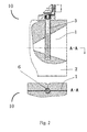
Fig. 1 shows a ray filter according to the present disclosure and a cross sectional view along line A-A, wherein both high and low-energy X-rays can pass through the ray filter; -
Fig. 2 shows a ray filter according to the present disclosure and a cross sectional view along line A-A, wherein only high-energy X-rays can pass through the ray filter; and -
Fig. 3 shows a ray filter according to an embodiment of the present disclosure and a cross sectional view along line A-A, where specific sizes of several parts are indicated. - Detail reference to embodiments of the present disclosure will be provided with example shown in the attached drawings. In the drawings, the same or like reference numbers refer to the same or like elements. Embodiments of the present disclosure will be described in detail with reference to the attached drawings.
- According to one embodiment of the present disclosure, as shown in
Figs. 1 and2 , aray filter 10 may be used in a dual-energy X ray inspection system configured to emit high-energy X-rays and low-energy X-rays alternately. In the dual-energy X ray inspection system, a dual-energy X-ray source is provided for emitting X-rays having high-energy and X-rays having low-energy alternately. Theray filter 10 is arranged in front of the X-ray source to filter out undesirable X-rays in a particular state so as to achieve selection of energy of the X-rays. Specifically, theray filter 10 is switchable between a first state where the ray filter is configured to allow the high-energy X-rays and the low-energy X-rays to pass therethrough and a second state where the ray filter is configured to only allow the high-energy X-rays to pass therethrough. - According to one embodiment of the present disclosure, the
ray filter 10 comprises: aray filter body 2 having a first slit opening 1 through which the X-rays are emitted; and ashielding member 3 movably provided in the ray filtration body in a direction perpendicular to a direction in which the rays are emitted and being transverse the first slit opening 1. - According to an embodiment of the present disclosure, the
first slit opening 1 is an elongate slit opening, which has a cross section that may be in the form of trumpet opening as shown in the figure, and a width corresponding to a width of the X-rays of the scan system, generally of 2∼3mm. The width may be set according to actual requirements. Theray filter body 2 is provided with a hole, into which theshielding member 3 is inserted. There is no exact requirement to the sizes of theshielding member 3 and the hole, as long as theshielding member 3 can be placed and rotated within the hole. Preferably, the size of theshielding member 3 substantially matches the size of the hole. The hole runs through the first slit opening 1, so that a portion of theshielding member 3 will face the whole of the first slit opening 1 when theshielding member 3 is inserted in to the hole. In other words, if theshielding member 3 is a solid piece, thefirst slit opening 1 will be completely blocked after theshielding member 3 is inserted into the hole. - According to an embodiment of the present disclosure, the
shielding member 3 comprises a second slit opening 6 and is arranged in the hole of theray filter body 2 so that it can be rotated. Theray filter 10 is switchable between the first state and the second state through rotation of theshielding member 3. Specifically, thesecond slit opening 6 is aligned with the first slit opening 1 in the first state so that thefirst slit opening 1 is not blocked and the first slit opening 1 forms a passage for allowing the rays to pass therethrough, at this time, the high-energy X-rays and low-energy X-rays can pass through thefirst slit opening 1. When theshielding member 3 is rotated, that is, when theray filter 10 is in the second state different from the first state, thesecond slit opening 6 is shifted from the first slit opening 1 so that thefirst slit opening 1 is blocked by the solid portion of theshielding member 3, thereby the low-energy X-rays being blocked by theshielding member 3 from being emitted through thefirst slit opening 1. According to an embodiment of the present disclosure, however, due to structure and arrangement of theshielding member 3, the high-energy X-rays having high penetrability can still transmit through a side wall having a limited thickness of the second slit opening 6 of theshielding member 3 while the low-energy X-rays are shielded by theshielding member 3. Thus, in the second state, the dual-energy X ray inspection system only emits X-rays having one type of energy so as to obtain a clear inspection image. - According to one embodiment of the present disclosure, the
shielding member 3 may be an elongate rod-like member. Theshielding member 3 may be a cylindrical rod. Theshielding member 3 may be a quadrate pillar with rounded ends. Theshielding member 3 may be other forms of pillars, as long as theshielding member 3 can be rotated and shield low-energy X-rays. Thesecond slit opening 6 is provided in the rod-like member, such that the second slit opening 6 runs through theshielding member 3 to form a slit-like through hole. The size of the second slit opening 6 may be designed according to actual requirements. - Since the
shielding member 3 is needed to allow the high-energy X-rays to transmit through theshielding member 3 while shield the low-energy X-rays, the material of theshielding member 3 may be selected as required so that the high-energy X-ray can transmit through theshielding member 3. Further, preferably, theshielding member 3 has a smaller size, so that the thickness of the side wall of the second slit opening 6 is small, thereby theshielding member 3 allowing the high-energy X-ray to transmit therethrough while shielding the low-energy X-rays. The thickness of the side wall may be determined depending on energy of actual low-energy and high-energy X-rays and the material of theshielding member 3. - The
ray filter 10 has a small total size, and thus may be easily applied in an X-ray inspection system. Since the size of theray filter 10 is small, shielding states can be selected by rotating theshielding member 3, and the ray filter has a simple and compact configuration, theray filter 10 may be directly added into the existing X-ray system without changing original design of the existing system, thereby greatly reducing complexity of the system. - According to an embodiment of the present disclosure, the
ray filter 10 may further comprise a shielding member drive device configured to drive theshielding member 3 to rotate so that theray filter 10 is switched between the first state and the second state through rotation of theshielding member 3, to match the energy switch of the X rays. In one embodiment, the shielding member drive device comprises a support structure and a gear transmission, wherein the gear transmission is supported in the support structure and engaged with an end of theshielding member 3 so that the gear transmission is capable of driving theshielding member 3 to rotate through engagement of the gear transmission with theshielding member 3. For example, the gear transmission may include a bevel gear, which is meshed with a gear 4 provided on theshielding member 3, as shown inFigs. 1 and2 . Other types of gear transmissions may be anticipated by those skilled in the art. In one embodiment, theshielding member 3 may be rotated manually. For example, an end of theshielding member 3 is provided with a handle, theshielding member 3 can be rotated by rotating the handle. - A particular embodiment of the
ray filter 10 according to the present disclosure is provided below. In this embodiment, the height of theray filter body 2 is 240mm. Theshielding member 3 may be a cylinder having a diameter of 28mm and the size of the second slit opening 6 in theshielding member 3 in a length direction of the shielding member 3 (as shown in the figures) is 100mm, which is selected according to an flare angle of the rays and the position of the shielding member, as long as thesecond slit opening 6 does not obstruct the low-energy X-rays from passing therethrough. - The material of the shielding member may include tungsten, tungsten alloy, or other high-Z material. At this time, the width of the second slit opening 6 may be about 6mm. In order to allow transmission of the high-energy X-rays, the
cylindrical shielding member 3 may be further machined, as shown in the figures, theshielding member 3 may be trimmed in a direction so that theshielding member 3 is thinned, thereby the total thickness of themachined shielding member 3 is 22mm (instead of the maximal thickness equal to the diameter of 28mm). When theshielding member 3 blocks the first slit opening 1, the low-energy X-rays cannot pass through theshielding member 3, while the high-energy X-ray can transmit through theshielding member 3 that is made of tungsten and has an effective total thickness of 16mm in a ray transmission direction. A portion of the shielding member within thefirst slit opening 1 is preferably sized so that the thickness of a wall of the part of the shielding member through which the X-rays transmit when passing through thefirst slit opening 1 is constant, thus the portion of the shielding member that is trimmed preferably has a transverse width greater than the width of thefirst slit opening 1, such that when theshielding member 3 blocks the first slit opening 1, the wall of the shielding member facing transmission of the X-rays is planar (rather than curved), and the face from which the X-rays are emitted is also planar, thereby a distance by which the high-energy X-rays transmit through theshielding member 3 is constant. The above disclosed sizes are only described as an example, other similar or appropriate sizes may be possible. - For example, when the shielding
member 3 is a pillar having other shapes, it is only necessary that the portion of the shielding member within the first slit opening is sufficient to block the low-energy X-rays and is configured so that portions of shielding member through which the high-energy X-rays transmit through has the same thickness. In other words, the shieldingmember 3 has planar incidence face and emitting face, so that high-energy X-rays transmit through portions of shielding member having the same thickness. That is, the shielding member has a planar exterior surface portion through which the high-energy X-rays are emitted in and out. - An embodiment of the present disclosure provides a dual-energy X ray inspection system comprising a dual-energy X-ray source configured to emit dual-energy X-rays, for example, to emit high-energy X-rays and low-energy X-rays. The dual-energy X ray inspection system further comprises the
ray filter 10 as described above. Theray filter 10 may be configured in a state where high-energy and low-energy X-rays may pass therethrough when it is required to emit the high-energy and low-energy X-rays from the dual-energy X ray inspection system. Theray filter 10 may be configured in a state where only high-energy X-rays may pass therethrough when it is only required to emit the high-energy X-rays from the dual-energy X ray inspection system. - Having described and shown the present disclosure in detail with reference to exemplary embodiment the present disclosure, it would be appreciated by those skilled in the art that various changes or modifications may be made in form and detail to these embodiments without departing from the principles and spirit of the present invention, the scope of which is defined in the claims and their equivalents.
- References to high-energy and low-energy X-rays may include X-rays with different energies below 200 keV or with energies above and below 200 keV. References to high-Z materials may include materials with atomic number 72 or above.
Claims (11)
- A ray filter for use in a dual-energy X ray inspection system configured to emit high-energy X-rays and low-energy X-rays, wherein
the ray filter is arranged in front of an X-ray source in a direction in which rays are emitted from the X-ray source, and is switchable between a first state where the ray filter is configured to allow the high-energy X-rays and the low-energy X-rays to pass therethrough and a second state where the ray filter is configured to only allow the high-energy X-rays to pass therethrough. - The ray filter according to claim 1, wherein the ray filter comprises:a ray filter body having a first slit opening through which the X-rays are emitted; anda shielding member movably provided in the ray filter body in a direction perpendicular to a direction in which the rays are emitted and being transverse the first slit opening.
- The ray filter according to claim 2, wherein the shielding member comprises a second slit opening and the shielding member is arranged to be rotated so that the ray filter is switchable between the first state and the second state.
- The ray filter according to claim 3, wherein
the second slit opening is aligned with the first slit opening in the first state so as to form a passage for allowing the rays to pass therethrough, and, in the second state, the second slit opening is shifted from the first slit opening so that the first slit opening is blocked by the shielding member. - The ray filter according to claim 2, wherein the shielding member is an elongate rod-like member, and the second slit opening runs through the rod-like member.
- The ray filter according to claim 5, wherein the shielding member is a cylindrical rod-like member.
- The ray filter according to claim 2, wherein
the ray filter comprises a shielding member drive device configured to drive the shielding member to rotate so that the ray filter is switched between the first state and the second state through rotation of the shielding member. - The ray filter according to claim 7, wherein
the shielding member drive device comprises a support structure and a gear transmission, the gear transmission being supported in the support structure and engaged with an end of the shielding member so that the gear transmission is capable of driving the shielding member to rotate through engagement of the gear transmission with the shielding member. - The ray filter according to claim 1, wherein
the shielding member is made of tungsten alloy. - The ray filter according to claim 2, wherein
the shielding member has a planar exterior surface portion through which the high-energy X-rays are emitted in and out. - A dual-energy X ray inspection system, comprising:a dual-energy X-ray source configured to emit dual-energy X-rays; andthe ray filter according to any one of claims 1-10.
Applications Claiming Priority (1)
| Application Number | Priority Date | Filing Date | Title |
|---|---|---|---|
| CN201410838393.3A CN104464871B (en) | 2014-12-30 | 2014-12-30 | Ray filter and dual energy X-ray inspection systems |
Publications (2)
| Publication Number | Publication Date |
|---|---|
| EP3041002A1 true EP3041002A1 (en) | 2016-07-06 |
| EP3041002B1 EP3041002B1 (en) | 2023-03-01 |
Family
ID=52910797
Family Applications (1)
| Application Number | Title | Priority Date | Filing Date |
|---|---|---|---|
| EP15203180.3A Active EP3041002B1 (en) | 2014-12-30 | 2015-12-30 | Ray filter and dual-energy x-ray inspection system |
Country Status (2)
| Country | Link |
|---|---|
| EP (1) | EP3041002B1 (en) |
| CN (1) | CN104464871B (en) |
Cited By (2)
| Publication number | Priority date | Publication date | Assignee | Title |
|---|---|---|---|---|
| US10658088B2 (en) | 2015-12-28 | 2020-05-19 | Tsinghua University | Collimator and inspection system having the same |
| US11786192B2 (en) | 2017-04-27 | 2023-10-17 | Medtronic Navigation, Inc. | Filter system and method for imaging a subject |
Families Citing this family (2)
| Publication number | Priority date | Publication date | Assignee | Title |
|---|---|---|---|---|
| CN104934092B (en) * | 2015-07-03 | 2017-08-01 | 中国计量科学研究院 | Filter |
| CN105181723B (en) * | 2015-09-28 | 2019-02-12 | 同方威视技术股份有限公司 | Dual energy ray scanning system, scanning method and inspection system |
Citations (11)
| Publication number | Priority date | Publication date | Assignee | Title |
|---|---|---|---|---|
| US4277685A (en) * | 1978-06-12 | 1981-07-07 | Ohio-Nuclear, Inc. | Adjustable collimator |
| US4592083A (en) * | 1984-03-27 | 1986-05-27 | Tokyo Shibaura Denki Kabushiki Kaisha | High speed x-ray shutter |
| US5838758A (en) * | 1990-08-10 | 1998-11-17 | Vivid Technologies | Device and method for inspection of baggage and other objects |
| FR2788599A1 (en) * | 1999-01-20 | 2000-07-21 | Heimann Systems | Producing color images differentiating elements, organic- and inorganic materials in e.g. lorry container at frontier, employs diverse penetrating radiations at low and high energies with appropriate moderation |
| WO2001059485A1 (en) * | 2000-02-10 | 2001-08-16 | American Science And Engineering, Inc. | Spectrally shaped x-ray inspection system |
| US20070104320A1 (en) * | 2005-11-10 | 2007-05-10 | Arenson Jerome S | X-ray flux management device |
| WO2008090518A1 (en) * | 2007-01-26 | 2008-07-31 | Koninklijke Philips Electronics N.V. | Spectrum-preserving heel effect compensation filter made from the same material as anode plate |
| GB2453641A (en) | 2007-10-05 | 2009-04-15 | Univ Tsinghua | Security inspection of liquid articles with dual energy CT imaging |
| GB2454782A (en) | 2007-11-15 | 2009-05-20 | Nuctech Co Ltd | Dual energy X-ray imaging for substance identification |
| WO2012160967A1 (en) * | 2011-05-23 | 2012-11-29 | 日立アロカメディカル株式会社 | X-ray generator |
| DE102012207626A1 (en) * | 2012-05-08 | 2013-11-14 | Siemens Aktiengesellschaft | X-ray apparatus for use in computed tomography for emitting multiple, different X-ray spectra of different average photon energies, comprises filter rotatably mounted relative to X-ray tube, and drive unit for rotational driving of filter |
Family Cites Families (7)
| Publication number | Priority date | Publication date | Assignee | Title |
|---|---|---|---|---|
| FR2621764A1 (en) * | 1987-10-13 | 1989-04-14 | Philips Massiot Mat Medic | RADIOLOGY APPARATUS WITH MOVABLE SLOTTED SCREEN IN VIDEO SYNCHRONIZATION |
| CN1274563C (en) * | 2003-08-23 | 2006-09-13 | 上海世鹏实验室科技发展有限公司 | Scanning detector of container |
| CN2901301Y (en) * | 2005-07-15 | 2007-05-16 | 北京中盾安民分析技术有限公司 | Portable double energy X-ray detector |
| CN102455305B (en) * | 2010-11-01 | 2014-06-18 | 北京中盾安民分析技术有限公司 | Image processing method used by device for detecting hidden matters on human body by using dual-energy X-rays |
| CN203204174U (en) * | 2013-04-27 | 2013-09-18 | 北京曼德克环境科技有限公司 | X-ray duel-energy transmission green channel vehicle detector |
| CN203705662U (en) * | 2013-12-26 | 2014-07-09 | 同方威视技术股份有限公司 | Inspection system for containers |
| CN204315245U (en) * | 2014-12-30 | 2015-05-06 | 同方威视技术股份有限公司 | Ray filtration unit and dual energy X-ray inspection systems |
-
2014
- 2014-12-30 CN CN201410838393.3A patent/CN104464871B/en active Active
-
2015
- 2015-12-30 EP EP15203180.3A patent/EP3041002B1/en active Active
Patent Citations (11)
| Publication number | Priority date | Publication date | Assignee | Title |
|---|---|---|---|---|
| US4277685A (en) * | 1978-06-12 | 1981-07-07 | Ohio-Nuclear, Inc. | Adjustable collimator |
| US4592083A (en) * | 1984-03-27 | 1986-05-27 | Tokyo Shibaura Denki Kabushiki Kaisha | High speed x-ray shutter |
| US5838758A (en) * | 1990-08-10 | 1998-11-17 | Vivid Technologies | Device and method for inspection of baggage and other objects |
| FR2788599A1 (en) * | 1999-01-20 | 2000-07-21 | Heimann Systems | Producing color images differentiating elements, organic- and inorganic materials in e.g. lorry container at frontier, employs diverse penetrating radiations at low and high energies with appropriate moderation |
| WO2001059485A1 (en) * | 2000-02-10 | 2001-08-16 | American Science And Engineering, Inc. | Spectrally shaped x-ray inspection system |
| US20070104320A1 (en) * | 2005-11-10 | 2007-05-10 | Arenson Jerome S | X-ray flux management device |
| WO2008090518A1 (en) * | 2007-01-26 | 2008-07-31 | Koninklijke Philips Electronics N.V. | Spectrum-preserving heel effect compensation filter made from the same material as anode plate |
| GB2453641A (en) | 2007-10-05 | 2009-04-15 | Univ Tsinghua | Security inspection of liquid articles with dual energy CT imaging |
| GB2454782A (en) | 2007-11-15 | 2009-05-20 | Nuctech Co Ltd | Dual energy X-ray imaging for substance identification |
| WO2012160967A1 (en) * | 2011-05-23 | 2012-11-29 | 日立アロカメディカル株式会社 | X-ray generator |
| DE102012207626A1 (en) * | 2012-05-08 | 2013-11-14 | Siemens Aktiengesellschaft | X-ray apparatus for use in computed tomography for emitting multiple, different X-ray spectra of different average photon energies, comprises filter rotatably mounted relative to X-ray tube, and drive unit for rotational driving of filter |
Cited By (3)
| Publication number | Priority date | Publication date | Assignee | Title |
|---|---|---|---|---|
| US10658088B2 (en) | 2015-12-28 | 2020-05-19 | Tsinghua University | Collimator and inspection system having the same |
| US11786192B2 (en) | 2017-04-27 | 2023-10-17 | Medtronic Navigation, Inc. | Filter system and method for imaging a subject |
| US12329553B2 (en) | 2017-04-27 | 2025-06-17 | Medtronic Navigation, Inc. | Filter system and method for imaging a subject |
Also Published As
| Publication number | Publication date |
|---|---|
| HK1204138A1 (en) | 2015-11-06 |
| CN104464871A (en) | 2015-03-25 |
| CN104464871B (en) | 2017-11-21 |
| EP3041002B1 (en) | 2023-03-01 |
Similar Documents
| Publication | Publication Date | Title |
|---|---|---|
| US9291582B2 (en) | Adjustable-jaw collimator | |
| US9014339B2 (en) | Versatile x-ray beam scanner | |
| DE10242920B4 (en) | Method for operating a computed tomography device and a device for carrying out the method | |
| CN102804326B (en) | Multi-view cargo scanner | |
| EP3041002B1 (en) | Ray filter and dual-energy x-ray inspection system | |
| KR102658750B1 (en) | Monochromatic X-ray imaging system and method | |
| GB2422759B (en) | Rotatable X-ray scan apparatus with cone beam offset | |
| US10224170B2 (en) | X-ray generating apparatus and X-ray fluoroscopyimaging system equipped with the same | |
| CA2723719A1 (en) | Adaptive scanning in an imaging system | |
| CN204315245U (en) | Ray filtration unit and dual energy X-ray inspection systems | |
| EP1772874B1 (en) | Focal point oriented aperture | |
| WO2007054769A3 (en) | Method and apparatus for radiation imaging | |
| WO2007111672A3 (en) | Concentric dual drum raster scanning beam system and method | |
| RU87810U1 (en) | X-RAY INSTALLATION FOR PREPARING AN IMAGE OF A QUICK PROCESSING PROCESS | |
| Fraix-Burnet et al. | Quantitative analysis of the optical jet in the QSO 3 C273 | |
| US20150023469A1 (en) | Irradiation field-limiting apparatus, x-ray-generating unit including the irradiation field-limiting apparatus, and x-ray radiography system including the irradiation field-limiting apparatus | |
| KR102336421B1 (en) | X-ray collimator and x-ray imaging apparatus comprising the same | |
| US11246546B2 (en) | Collimator and radiological equipment | |
| HK1204138B (en) | Ray filtering device and dual-energy x-ray inspection system | |
| US3411000A (en) | X-ray diffractometer diaphragm which is synchronously rotated with the specimen | |
| DE2262982C3 (en) | Tire tester | |
| DE102009047672A1 (en) | X-ray optical construction with two focusing elements | |
| KR200474824Y1 (en) | A functionality Improved collimator | |
| RU102484U1 (en) | X-ray screening raster | |
| JP2014008360A (en) | Radiation generator and radiographic system |
Legal Events
| Date | Code | Title | Description |
|---|---|---|---|
| PUAI | Public reference made under article 153(3) epc to a published international application that has entered the european phase |
Free format text: ORIGINAL CODE: 0009012 |
|
| 17P | Request for examination filed |
Effective date: 20151230 |
|
| AK | Designated contracting states |
Kind code of ref document: A1 Designated state(s): AL AT BE BG CH CY CZ DE DK EE ES FI FR GB GR HR HU IE IS IT LI LT LU LV MC MK MT NL NO PL PT RO RS SE SI SK SM TR |
|
| AX | Request for extension of the european patent |
Extension state: BA ME |
|
| STAA | Information on the status of an ep patent application or granted ep patent |
Free format text: STATUS: EXAMINATION IS IN PROGRESS |
|
| 17Q | First examination report despatched |
Effective date: 20191113 |
|
| GRAP | Despatch of communication of intention to grant a patent |
Free format text: ORIGINAL CODE: EPIDOSNIGR1 |
|
| STAA | Information on the status of an ep patent application or granted ep patent |
Free format text: STATUS: GRANT OF PATENT IS INTENDED |
|
| INTG | Intention to grant announced |
Effective date: 20221128 |
|
| GRAS | Grant fee paid |
Free format text: ORIGINAL CODE: EPIDOSNIGR3 |
|
| GRAA | (expected) grant |
Free format text: ORIGINAL CODE: 0009210 |
|
| STAA | Information on the status of an ep patent application or granted ep patent |
Free format text: STATUS: THE PATENT HAS BEEN GRANTED |
|
| AK | Designated contracting states |
Kind code of ref document: B1 Designated state(s): AL AT BE BG CH CY CZ DE DK EE ES FI FR GB GR HR HU IE IS IT LI LT LU LV MC MK MT NL NO PL PT RO RS SE SI SK SM TR |
|
| REG | Reference to a national code |
Ref country code: GB Ref legal event code: FG4D |
|
| REG | Reference to a national code |
Ref country code: CH Ref legal event code: EP Ref country code: AT Ref legal event code: REF Ref document number: 1551560 Country of ref document: AT Kind code of ref document: T Effective date: 20230315 |
|
| REG | Reference to a national code |
Ref country code: DE Ref legal event code: R096 Ref document number: 602015082638 Country of ref document: DE |
|
| REG | Reference to a national code |
Ref country code: IE Ref legal event code: FG4D |
|
| REG | Reference to a national code |
Ref country code: LT Ref legal event code: MG9D |
|
| REG | Reference to a national code |
Ref country code: NL Ref legal event code: MP Effective date: 20230301 |
|
| P01 | Opt-out of the competence of the unified patent court (upc) registered |
Effective date: 20230526 |
|
| PG25 | Lapsed in a contracting state [announced via postgrant information from national office to epo] |
Ref country code: RS Free format text: LAPSE BECAUSE OF FAILURE TO SUBMIT A TRANSLATION OF THE DESCRIPTION OR TO PAY THE FEE WITHIN THE PRESCRIBED TIME-LIMIT Effective date: 20230301 Ref country code: NO Free format text: LAPSE BECAUSE OF FAILURE TO SUBMIT A TRANSLATION OF THE DESCRIPTION OR TO PAY THE FEE WITHIN THE PRESCRIBED TIME-LIMIT Effective date: 20230601 Ref country code: LV Free format text: LAPSE BECAUSE OF FAILURE TO SUBMIT A TRANSLATION OF THE DESCRIPTION OR TO PAY THE FEE WITHIN THE PRESCRIBED TIME-LIMIT Effective date: 20230301 Ref country code: LT Free format text: LAPSE BECAUSE OF FAILURE TO SUBMIT A TRANSLATION OF THE DESCRIPTION OR TO PAY THE FEE WITHIN THE PRESCRIBED TIME-LIMIT Effective date: 20230301 Ref country code: HR Free format text: LAPSE BECAUSE OF FAILURE TO SUBMIT A TRANSLATION OF THE DESCRIPTION OR TO PAY THE FEE WITHIN THE PRESCRIBED TIME-LIMIT Effective date: 20230301 Ref country code: ES Free format text: LAPSE BECAUSE OF FAILURE TO SUBMIT A TRANSLATION OF THE DESCRIPTION OR TO PAY THE FEE WITHIN THE PRESCRIBED TIME-LIMIT Effective date: 20230301 |
|
| REG | Reference to a national code |
Ref country code: AT Ref legal event code: MK05 Ref document number: 1551560 Country of ref document: AT Kind code of ref document: T Effective date: 20230301 |
|
| PG25 | Lapsed in a contracting state [announced via postgrant information from national office to epo] |
Ref country code: SE Free format text: LAPSE BECAUSE OF FAILURE TO SUBMIT A TRANSLATION OF THE DESCRIPTION OR TO PAY THE FEE WITHIN THE PRESCRIBED TIME-LIMIT Effective date: 20230301 Ref country code: PL Free format text: LAPSE BECAUSE OF FAILURE TO SUBMIT A TRANSLATION OF THE DESCRIPTION OR TO PAY THE FEE WITHIN THE PRESCRIBED TIME-LIMIT Effective date: 20230301 Ref country code: NL Free format text: LAPSE BECAUSE OF FAILURE TO SUBMIT A TRANSLATION OF THE DESCRIPTION OR TO PAY THE FEE WITHIN THE PRESCRIBED TIME-LIMIT Effective date: 20230301 Ref country code: GR Free format text: LAPSE BECAUSE OF FAILURE TO SUBMIT A TRANSLATION OF THE DESCRIPTION OR TO PAY THE FEE WITHIN THE PRESCRIBED TIME-LIMIT Effective date: 20230602 Ref country code: FI Free format text: LAPSE BECAUSE OF FAILURE TO SUBMIT A TRANSLATION OF THE DESCRIPTION OR TO PAY THE FEE WITHIN THE PRESCRIBED TIME-LIMIT Effective date: 20230301 |
|
| PG25 | Lapsed in a contracting state [announced via postgrant information from national office to epo] |
Ref country code: SM Free format text: LAPSE BECAUSE OF FAILURE TO SUBMIT A TRANSLATION OF THE DESCRIPTION OR TO PAY THE FEE WITHIN THE PRESCRIBED TIME-LIMIT Effective date: 20230301 Ref country code: RO Free format text: LAPSE BECAUSE OF FAILURE TO SUBMIT A TRANSLATION OF THE DESCRIPTION OR TO PAY THE FEE WITHIN THE PRESCRIBED TIME-LIMIT Effective date: 20230301 Ref country code: PT Free format text: LAPSE BECAUSE OF FAILURE TO SUBMIT A TRANSLATION OF THE DESCRIPTION OR TO PAY THE FEE WITHIN THE PRESCRIBED TIME-LIMIT Effective date: 20230703 Ref country code: EE Free format text: LAPSE BECAUSE OF FAILURE TO SUBMIT A TRANSLATION OF THE DESCRIPTION OR TO PAY THE FEE WITHIN THE PRESCRIBED TIME-LIMIT Effective date: 20230301 Ref country code: CZ Free format text: LAPSE BECAUSE OF FAILURE TO SUBMIT A TRANSLATION OF THE DESCRIPTION OR TO PAY THE FEE WITHIN THE PRESCRIBED TIME-LIMIT Effective date: 20230301 Ref country code: AT Free format text: LAPSE BECAUSE OF FAILURE TO SUBMIT A TRANSLATION OF THE DESCRIPTION OR TO PAY THE FEE WITHIN THE PRESCRIBED TIME-LIMIT Effective date: 20230301 |
|
| PG25 | Lapsed in a contracting state [announced via postgrant information from national office to epo] |
Ref country code: SK Free format text: LAPSE BECAUSE OF FAILURE TO SUBMIT A TRANSLATION OF THE DESCRIPTION OR TO PAY THE FEE WITHIN THE PRESCRIBED TIME-LIMIT Effective date: 20230301 Ref country code: IS Free format text: LAPSE BECAUSE OF FAILURE TO SUBMIT A TRANSLATION OF THE DESCRIPTION OR TO PAY THE FEE WITHIN THE PRESCRIBED TIME-LIMIT Effective date: 20230701 |
|
| REG | Reference to a national code |
Ref country code: DE Ref legal event code: R097 Ref document number: 602015082638 Country of ref document: DE |
|
| PLBE | No opposition filed within time limit |
Free format text: ORIGINAL CODE: 0009261 |
|
| STAA | Information on the status of an ep patent application or granted ep patent |
Free format text: STATUS: NO OPPOSITION FILED WITHIN TIME LIMIT |
|
| PG25 | Lapsed in a contracting state [announced via postgrant information from national office to epo] |
Ref country code: SI Free format text: LAPSE BECAUSE OF FAILURE TO SUBMIT A TRANSLATION OF THE DESCRIPTION OR TO PAY THE FEE WITHIN THE PRESCRIBED TIME-LIMIT Effective date: 20230301 Ref country code: DK Free format text: LAPSE BECAUSE OF FAILURE TO SUBMIT A TRANSLATION OF THE DESCRIPTION OR TO PAY THE FEE WITHIN THE PRESCRIBED TIME-LIMIT Effective date: 20230301 |
|
| 26N | No opposition filed |
Effective date: 20231204 |
|
| PG25 | Lapsed in a contracting state [announced via postgrant information from national office to epo] |
Ref country code: IT Free format text: LAPSE BECAUSE OF FAILURE TO SUBMIT A TRANSLATION OF THE DESCRIPTION OR TO PAY THE FEE WITHIN THE PRESCRIBED TIME-LIMIT Effective date: 20230301 |
|
| REG | Reference to a national code |
Ref country code: CH Ref legal event code: PL |
|
| PG25 | Lapsed in a contracting state [announced via postgrant information from national office to epo] |
Ref country code: LU Free format text: LAPSE BECAUSE OF NON-PAYMENT OF DUE FEES Effective date: 20231230 |
|
| PG25 | Lapsed in a contracting state [announced via postgrant information from national office to epo] |
Ref country code: MC Free format text: LAPSE BECAUSE OF FAILURE TO SUBMIT A TRANSLATION OF THE DESCRIPTION OR TO PAY THE FEE WITHIN THE PRESCRIBED TIME-LIMIT Effective date: 20230301 |
|
| REG | Reference to a national code |
Ref country code: BE Ref legal event code: MM Effective date: 20231231 |
|
| PG25 | Lapsed in a contracting state [announced via postgrant information from national office to epo] |
Ref country code: MC Free format text: LAPSE BECAUSE OF FAILURE TO SUBMIT A TRANSLATION OF THE DESCRIPTION OR TO PAY THE FEE WITHIN THE PRESCRIBED TIME-LIMIT Effective date: 20230301 Ref country code: LU Free format text: LAPSE BECAUSE OF NON-PAYMENT OF DUE FEES Effective date: 20231230 |
|
| REG | Reference to a national code |
Ref country code: IE Ref legal event code: MM4A |
|
| PG25 | Lapsed in a contracting state [announced via postgrant information from national office to epo] |
Ref country code: IE Free format text: LAPSE BECAUSE OF NON-PAYMENT OF DUE FEES Effective date: 20231230 |
|
| PG25 | Lapsed in a contracting state [announced via postgrant information from national office to epo] |
Ref country code: BE Free format text: LAPSE BECAUSE OF NON-PAYMENT OF DUE FEES Effective date: 20231231 |
|
| PG25 | Lapsed in a contracting state [announced via postgrant information from national office to epo] |
Ref country code: CH Free format text: LAPSE BECAUSE OF NON-PAYMENT OF DUE FEES Effective date: 20231231 |
|
| PG25 | Lapsed in a contracting state [announced via postgrant information from national office to epo] |
Ref country code: IE Free format text: LAPSE BECAUSE OF NON-PAYMENT OF DUE FEES Effective date: 20231230 Ref country code: CH Free format text: LAPSE BECAUSE OF NON-PAYMENT OF DUE FEES Effective date: 20231231 Ref country code: BE Free format text: LAPSE BECAUSE OF NON-PAYMENT OF DUE FEES Effective date: 20231231 |
|
| PG25 | Lapsed in a contracting state [announced via postgrant information from national office to epo] |
Ref country code: BG Free format text: LAPSE BECAUSE OF FAILURE TO SUBMIT A TRANSLATION OF THE DESCRIPTION OR TO PAY THE FEE WITHIN THE PRESCRIBED TIME-LIMIT Effective date: 20230301 |
|
| PG25 | Lapsed in a contracting state [announced via postgrant information from national office to epo] |
Ref country code: BG Free format text: LAPSE BECAUSE OF FAILURE TO SUBMIT A TRANSLATION OF THE DESCRIPTION OR TO PAY THE FEE WITHIN THE PRESCRIBED TIME-LIMIT Effective date: 20230301 |
|
| PG25 | Lapsed in a contracting state [announced via postgrant information from national office to epo] |
Ref country code: CY Free format text: LAPSE BECAUSE OF FAILURE TO SUBMIT A TRANSLATION OF THE DESCRIPTION OR TO PAY THE FEE WITHIN THE PRESCRIBED TIME-LIMIT; INVALID AB INITIO Effective date: 20151230 |
|
| PG25 | Lapsed in a contracting state [announced via postgrant information from national office to epo] |
Ref country code: HU Free format text: LAPSE BECAUSE OF FAILURE TO SUBMIT A TRANSLATION OF THE DESCRIPTION OR TO PAY THE FEE WITHIN THE PRESCRIBED TIME-LIMIT; INVALID AB INITIO Effective date: 20151230 |
|
| PG25 | Lapsed in a contracting state [announced via postgrant information from national office to epo] |
Ref country code: TR Free format text: LAPSE BECAUSE OF FAILURE TO SUBMIT A TRANSLATION OF THE DESCRIPTION OR TO PAY THE FEE WITHIN THE PRESCRIBED TIME-LIMIT Effective date: 20230301 |
|
| PGFP | Annual fee paid to national office [announced via postgrant information from national office to epo] |
Ref country code: GB Payment date: 20251111 Year of fee payment: 11 |
|
| PGFP | Annual fee paid to national office [announced via postgrant information from national office to epo] |
Ref country code: FR Payment date: 20251125 Year of fee payment: 11 |
|
| PGFP | Annual fee paid to national office [announced via postgrant information from national office to epo] |
Ref country code: DE Payment date: 20251222 Year of fee payment: 11 |