EP3040744A1 - X-ray beam intensity monitoring device and x-ray inspection system - Google Patents
X-ray beam intensity monitoring device and x-ray inspection system Download PDFInfo
- Publication number
- EP3040744A1 EP3040744A1 EP15203078.9A EP15203078A EP3040744A1 EP 3040744 A1 EP3040744 A1 EP 3040744A1 EP 15203078 A EP15203078 A EP 15203078A EP 3040744 A1 EP3040744 A1 EP 3040744A1
- Authority
- EP
- European Patent Office
- Prior art keywords
- ray
- intensity
- ray beam
- signal
- detecting module
- Prior art date
- Legal status (The legal status is an assumption and is not a legal conclusion. Google has not performed a legal analysis and makes no representation as to the accuracy of the status listed.)
- Granted
Links
Images



Classifications
-
- G—PHYSICS
- G01—MEASURING; TESTING
- G01T—MEASUREMENT OF NUCLEAR OR X-RADIATION
- G01T1/00—Measuring X-radiation, gamma radiation, corpuscular radiation, or cosmic radiation
- G01T1/16—Measuring radiation intensity
- G01T1/1603—Measuring radiation intensity with a combination of at least two different types of detectors
-
- G—PHYSICS
- G01—MEASURING; TESTING
- G01T—MEASUREMENT OF NUCLEAR OR X-RADIATION
- G01T1/00—Measuring X-radiation, gamma radiation, corpuscular radiation, or cosmic radiation
- G01T1/16—Measuring radiation intensity
- G01T1/20—Measuring radiation intensity with scintillation detectors
- G01T1/2006—Measuring radiation intensity with scintillation detectors using a combination of a scintillator and photodetector which measures the means radiation intensity
-
- H—ELECTRICITY
- H04—ELECTRIC COMMUNICATION TECHNIQUE
- H04N—PICTORIAL COMMUNICATION, e.g. TELEVISION
- H04N5/00—Details of television systems
- H04N5/44—Receiver circuitry for the reception of television signals according to analogue transmission standards
- H04N5/57—Control of contrast or brightness
-
- H—ELECTRICITY
- H05—ELECTRIC TECHNIQUES NOT OTHERWISE PROVIDED FOR
- H05G—X-RAY TECHNIQUE
- H05G1/00—X-ray apparatus involving X-ray tubes; Circuits therefor
- H05G1/08—Electrical details
- H05G1/26—Measuring, controlling or protecting
- H05G1/30—Controlling
- H05G1/36—Temperature of anode; Brightness of image power
-
- H—ELECTRICITY
- H10—SEMICONDUCTOR DEVICES; ELECTRIC SOLID-STATE DEVICES NOT OTHERWISE PROVIDED FOR
- H10K—ORGANIC ELECTRIC SOLID-STATE DEVICES
- H10K39/00—Integrated devices, or assemblies of multiple devices, comprising at least one organic radiation-sensitive element covered by group H10K30/00
-
- G—PHYSICS
- G01—MEASURING; TESTING
- G01T—MEASUREMENT OF NUCLEAR OR X-RADIATION
- G01T1/00—Measuring X-radiation, gamma radiation, corpuscular radiation, or cosmic radiation
- G01T1/16—Measuring radiation intensity
- G01T1/1606—Measuring radiation intensity with other specified detectors not provided for in the other subgroups of G01T1/16
-
- G—PHYSICS
- G01—MEASURING; TESTING
- G01T—MEASUREMENT OF NUCLEAR OR X-RADIATION
- G01T1/00—Measuring X-radiation, gamma radiation, corpuscular radiation, or cosmic radiation
- G01T1/16—Measuring radiation intensity
- G01T1/17—Circuit arrangements not adapted to a particular type of detector
-
- G—PHYSICS
- G01—MEASURING; TESTING
- G01T—MEASUREMENT OF NUCLEAR OR X-RADIATION
- G01T7/00—Details of radiation-measuring instruments
-
- G—PHYSICS
- G01—MEASURING; TESTING
- G01V—GEOPHYSICS; GRAVITATIONAL MEASUREMENTS; DETECTING MASSES OR OBJECTS; TAGS
- G01V5/00—Prospecting or detecting by the use of ionising radiation, e.g. of natural or induced radioactivity
- G01V5/20—Detecting prohibited goods, e.g. weapons, explosives, hazardous substances, contraband or smuggled objects
- G01V5/22—Active interrogation, i.e. by irradiating objects or goods using external radiation sources, e.g. using gamma rays or cosmic rays
-
- G—PHYSICS
- G06—COMPUTING OR CALCULATING; COUNTING
- G06T—IMAGE DATA PROCESSING OR GENERATION, IN GENERAL
- G06T1/00—General purpose image data processing
- G06T1/0014—Image feed-back for automatic industrial control, e.g. robot with camera
-
- G—PHYSICS
- G09—EDUCATION; CRYPTOGRAPHY; DISPLAY; ADVERTISING; SEALS
- G09G—ARRANGEMENTS OR CIRCUITS FOR CONTROL OF INDICATING DEVICES USING STATIC MEANS TO PRESENT VARIABLE INFORMATION
- G09G2320/00—Control of display operating conditions
- G09G2320/06—Adjustment of display parameters
- G09G2320/0626—Adjustment of display parameters for control of overall brightness
-
- G—PHYSICS
- G09—EDUCATION; CRYPTOGRAPHY; DISPLAY; ADVERTISING; SEALS
- G09G—ARRANGEMENTS OR CIRCUITS FOR CONTROL OF INDICATING DEVICES USING STATIC MEANS TO PRESENT VARIABLE INFORMATION
- G09G2320/00—Control of display operating conditions
- G09G2320/06—Adjustment of display parameters
- G09G2320/0626—Adjustment of display parameters for control of overall brightness
- G09G2320/0646—Modulation of illumination source brightness and image signal correlated to each other
-
- G—PHYSICS
- G21—NUCLEAR PHYSICS; NUCLEAR ENGINEERING
- G21K—HANDLING OF PARTICLES OR IONISING RADIATION NOT OTHERWISE PROVIDED FOR; IRRADIATION DEVICES; GAMMA RAY OR X-RAY MICROSCOPES
- G21K1/00—Arrangements for handling particles or ionising radiation, e.g. focusing or moderating
- G21K1/02—Arrangements for handling particles or ionising radiation, e.g. focusing or moderating using diaphragms, collimators
-
- H—ELECTRICITY
- H04—ELECTRIC COMMUNICATION TECHNIQUE
- H04N—PICTORIAL COMMUNICATION, e.g. TELEVISION
- H04N25/00—Circuitry of solid-state image sensors [SSIS]; Control thereof
- H04N25/70—SSIS architectures; Circuits associated therewith
- H04N25/709—Circuitry for control of the power supply
Definitions
- the present invention relates to the technical field of X-ray application, and particularly relates to an X-ray beam intensity monitoring device and an X-ray inspection system.
- an X-ray emitting device is mainly an electron accelerator or an X-ray tube.
- the X-ray emitting device and a detector array adopted to receive X-ray are placed on both sides of an inspected object.
- an X-ray beam emitted by the X-ray emitting device contains both a working beam directly irradiated on the detector array and a redundant beam irradiated on the outside of the detector array.
- the X-ray beam is usually a fan-shaped beam, the fan-shaped beam is perpendicular to the ground, and the width of the working beam in the fan-shaped beam at the detector array is generally required to be approximately equal to the width of the detector array. For this reason, a collimator is often arranged between the X-ray emitting device and the detector array. The collimator is adopted to shield the redundant beam in the X-ray beam. When an object is inspected, the collimator is located between the X-ray emitting device and the inspected object.
- the intensity of the X-ray beam is monitored by means of dose monitoring or brightness monitoring of the X-ray beam.
- Dose monitoring means monitoring the dose intensity of the X-ray beam, judging whether the dose intensity exceeds a regulated dose value, and if so, and sending a dose monitoring signal to perform such operations as alarming or cutting off the power supply of the X-ray emitting device and the like.
- Brightness monitoring means collecting a fluctuation change value of the intensity of the X-ray beam within each measurement period and sending a brightness correction signal to correct the value collected by the detector array, so as to obtain more accurate information of the inspected object.
- a dose monitoring device and a brightness monitoring device of the X-ray beam are common in the X-ray inspection system, and the two devices independently exist in the X-ray inspection system under normal conditions.
- the X-ray inspection system and the X-ray beam intensity monitoring device thereof in the prior art will be illustrated below by taking it as an example that the electron accelerator is used as the X-ray emitting device of the X-ray inspection system.
- the dose monitoring device in the prior art includes a detecting module, the detecting module is directly placed at the outlet of the X-ray beam of the electron accelerator in general and is located in a box body of the electron accelerator, X-rays directly penetrate through the sensitive volume of the detecting module and irradiate on the inspected object.
- the monitoring method adopted by the brightness monitoring device in the prior art is to collect a brightness signal by using a redundancy detector at the upper edge region of the fan-shaped beam in the detector array for X-ray inspection and send the brightness correction signal to correct the value collected by the detector array.
- the redundancy detector of the detector array is susceptible to interference of a reflected signal, mechanical deformation and other factors of the inspected object.
- the X-ray emitting device is the electron accelerator
- the X-ray beam intensity on the "main beam" direction (i.e., the direction of the electron beam) of the X-ray beam is large, the larger the included angle of a position with the "main beam” is, the weaker the X-ray beam intensity is, and the X-ray beam intensity of the region where the redundancy detector is located is generally weak, so that the monitoring result is affected ultimately.
- the purpose of the present invention is to provide an X-ray beam intensity monitoring device and an X-ray inspection system, which can improve the service efficiency of the X-ray beam intensity monitoring device.
- the other purpose of the present invention is to provide an X-ray inspection system, and the monitoring result of X-ray beam intensity of the X-ray inspection system is more accurate and reliable.
- a first aspect of the present invention provides an X-ray beam intensity monitoring device, including an intensity detecting module and a data processing module, wherein the intensity detecting module is adopted to be irradiated by the X-ray beam and send a detecting signal, the data processing module is coupled with the intensity detecting module to receive the detecting signal and output an X-ray beam intensity monitoring signal, wherein the X-ray beam intensity monitoring signal includes a dose monitoring signal of the X-ray beam and a brightness correction signal of the X-ray beam.
- the X-ray beam intensity monitoring device includes a plurality of intensity detecting modules, and the plurality of intensity detecting modules are coupled with the same data processing module.
- the intensity detecting modules are independently sealed respectively.
- the data processing module includes an integrating amplifier and a signal conversion device, the integrating amplifier is coupled with the intensity detecting module to receive the detecting signal and output a voltage signal, and the signal conversion device is coupled with the integrating amplifier to receive the voltage signal and output the dose monitoring signal and the brightness correction signal.
- the signal conversion device includes a voltage comparator and an analog-digital converter
- the voltage comparator is coupled with the integrating amplifier to receive the voltage signal and output a level signal to serve as the dose monitoring signal
- the analog-digital converter is coupled with the integrating amplifier to receive the voltage signal and output a digital signal to serve as the brightness correction signal.
- the intensity detecting module is a scintillation detecting module or a gas detecting module.
- the intensity detecting module is a scintillation detecting module
- the scintillation detecting module includes a scintillator, a photosensor and a shielding layer, one end of the scintillator is coupled with the photosensor, and the shielding layer is arranged on the periphery of the photosensor.
- a second aspect of the present invention provides an X-ray inspection system, including an X-ray emitting device, a detector array and an X-ray beam intensity monitoring device, wherein the X-ray beam intensity monitoring device is the X-ray beam intensity monitoring device in any item in the first aspect of the present invention.
- an X-ray beam emitted by the X-ray emitting device includes a working beam irradiated on the detector array and a redundant beam irradiated on the outside of the detector array, and the intensity detecting module of the X-ray beam intensity monitoring device is arranged between the X-ray emitting device and the detector array to be irradiated by the redundant beam and send the detecting signal.
- the X-ray inspection system further includes a collimator, and the intensity detecting module is located between the X-ray emitting device and the collimator.
- the X-ray beam intensity monitoring device includes the intensity detecting module and the data processing module, the intensity detecting module is adopted to be irradiated by the X-ray beam and send the detecting signal, the data processing module is coupled with the intensity detecting module to receive the detecting signal and output the X-ray beam intensity monitoring signal, wherein the X-ray beam intensity monitoring signal includes the dose monitoring signal of the X-ray beam and the brightness correction signal of the X-ray beam, so that the X-ray beam intensity monitoring device can simultaneously perform dose monitoring and brightness monitoring, which improves the service efficiency of the X-ray beam intensity monitoring device.
- the present invention provides an X-ray inspection system, including an X-ray emitting device, a detector array and an X-ray beam intensity monitoring device, wherein an X-ray beam emitted by the X-ray emitting device includes a working beam irradiated on the detector array and a redundant beam irradiated on the outside of the detector array, the X-ray beam intensity monitoring device includes an intensity detecting module and a data processing module, the intensity detecting module is arranged between the X-ray emitting device and the detector array to be irradiated by the redundant beam and send a detecting signal, and the data processing module is coupled with the intensity detecting module to receive the detecting signal and output an X-ray beam intensity monitoring signal.
- the X-ray inspection system further includes a collimator located between the X-ray emitting device and the detector array, and the intensity detecting module is located between the X-ray emitting device and the collimator.
- the X-ray beam intensity monitoring device includes a plurality of intensity detecting modules which are symmetrically arranged relative to the working beam.
- the X-ray beam is a fan-shaped beam
- the intensity detecting module is located on the sector side of the fan-shaped beam.
- the X-ray beam intensity monitoring signal includes a dose monitoring signal of the X-ray beam and/or a brightness correction signal of the X-ray beam.
- the data processing module includes an integrating amplifier and a signal conversion device, the integrating amplifier is coupled with the intensity detecting module to receive the detecting signal and output a voltage signal, and the signal conversion device is coupled with the integrating amplifier to receive the voltage signal and output the X-ray beam intensity monitoring signal.
- the signal conversion device includes at least one of a voltage comparator and an analog-digital converter, wherein the voltage comparator is coupled with the integrating amplifier to receive the voltage signal and output a level signal to serve as the dose monitoring signal of the X-ray beam, and the analog-digital converter is coupled with the integrating amplifier to receive the voltage signal and output a digital signal to serve as the brightness correction signal of the X-ray beam.
- the voltage comparator is coupled with the integrating amplifier to receive the voltage signal and output a level signal to serve as the dose monitoring signal of the X-ray beam
- the analog-digital converter is coupled with the integrating amplifier to receive the voltage signal and output a digital signal to serve as the brightness correction signal of the X-ray beam.
- the intensity detecting module is a scintillation detecting module or a gas detecting module.
- the intensity detecting module is a scintillation detecting module
- the scintillation detecting module includes a scintillator, a photosensor and a shielding layer, one end of the scintillator is coupled with the photosensor, the scintillator is located between the photosensor and the working beam to irradiate the redundant beam on the scintillator, and the shielding layer is arranged on the periphery of the photosensor.
- the intensity detecting module is a gas detecting module
- the gas detecting module includes a high-voltage plate electrode, a collection plate electrode and a working gas
- the high-voltage plate electrode is located between the X-ray emitting device and the collection plate electrode and is vertical to the incidence direction of the X-ray beam to irradiate the redundant beam on the high-voltage plate electrode
- the working gas is located between the high-voltage plate electrode and the collection plate electrode.
- the X-ray beam intensity monitoring device includes the intensity detecting module and the data processing module, the intensity detecting module is arranged between the emitting device and the detector array to be irradiated by the redundant beam and send the detecting signal, and the data processing module is coupled with the intensity detecting module to receive the detecting signal and output the X-ray beam intensity monitoring signal.
- the intensity detecting module of the X-ray inspection system adopts the redundant beam of the X-ray beam, and the intensity detecting module is basically free from the influence of the X-ray emitting device and the inspected object, so that the monitoring result of the X-ray beam intensity can be more accurate and reliable. Further, since the intensity detecting module has no influence on the working beam, thereby having no influence on the intensity of the working beam arriving at the inspected object and the detector array.
- Fig. 1 to Fig. 5 show an X-ray inspection system in the first embodiment of the present invention.
- Fig. 1 is a layout schematic diagram of an X-ray inspection system in the first embodiment of the present invention.
- Fig. 2 is a sectional schematic diagram of a B-B direction of the X-ray inspection system as shown in Fig. 1 .
- the X-ray inspection system in the first embodiment includes an X-ray emitting device adopted to emit X-rays, a collimator 3, a detector array 2 used in X-ray inspection and an X-ray beam intensity monitoring device.
- the X-ray beam intensity monitoring device is adopted to monitor the X-ray beam intensity of the X-ray emitting device.
- the X-ray beam intensity monitoring device includes an intensity detecting module and a data processing module.
- the data processing module is coupled with the intensity detecting module to receive the detecting signal sent by the intensity detecting module and output an X-ray beam intensity monitoring signal.
- the X-ray beam intensity monitoring signal includes a dose monitoring signal of the X-ray beam and a brightness correction signal of the X-ray beam.
- the X-ray beam intensity monitoring device can simultaneously perform dose monitoring and brightness monitoring, thereby improving the service efficiency of the X-ray beam intensity monitoring device.
- An X-ray beam emitted by the X-ray emitting device includes a working beam irradiated on the detector array 2 and a redundant beam irradiated on the outside of the detector array 2.
- the intensity detecting module of the X-ray beam intensity monitoring device is preferably arranged between the emitting device and the detector array 2 to be irradiated by the redundant beam and send a detecting signal.
- the intensity detecting module of the X-ray inspection system adopts the redundant beam of the X-ray beam, and the intensity detecting module is basically free from the influence of the X-ray emitting device and the inspected object 4, so that the monitoring result of the X-ray beam intensity can be more accurate and reliable. Further, since the intensity detecting module has no influence on the working beam, thereby having no influence on the intensity of the working beam arriving at the inspected object 4 and the detector array 2.
- the X-ray emitting device is an electron accelerator 1.
- the X-ray emitting device can be other X-ray emitting devices, such as an X-ray tube, etc.
- the collimator 3 is located between the X-ray emitting device and the detector array 2.
- the collimator 3 is adopted to shield the redundant beam.
- the collimator 3 is located between the X-ray emitting device and the inspected object 4, and the working beam of the X-ray beam irradiates the inspected object 4 and the detector array 2 after passing through the collimator 3.
- the intensity detecting module is located between the X-ray emitting device and the collimator 3. Owing to this arrangement, the direct electromagnetic interference from the electron accelerator 1 is avoided, and meanwhile the monitoring result of the X-ray beam intensity will not be influenced by the arrangement of the collimator 3.
- the X-ray beam intensity monitoring device includes a plurality of intensity detecting modules which are symmetrically arranged relative to the working beam.
- the detecting signals sent by the intensity detecting modules can compensate each other, so that the monitoring result of the X-ray beam intensity can be more accurate and reliable compared with that when only a single intensity detecting module is arranged.
- Two intensity detecting modules are specifically arranged in the first embodiment. In other non-shown embodiments, more intensity detecting modules, for example 4, can be arranged.
- the working beam is a fan-shaped beam
- the intensity detecting module is located on the sector side of the fan-shaped beam. Owing to this arrangement, the intensity detecting module is located at a "main beam" of the X-ray beam and is closer to the central position of the X-ray beam, so that information of the X-ray beam identify can be provided more effectively.
- the sector of the fan-shaped beam is perpendicular to the ground
- one side where the electron accelerator 1 is located is a front side
- one side where the detector array 2 is located is a back side
- one intensity detecting module (called a left detecting module and a right detecting module below) is respectively arranged on the left and right sides of the sector of the fan-shaped beam.
- the left detecting module and the right detecting module are placed between the electron accelerator 1 and the collimator 3 and are adopted to generate the X-ray beam intensity monitoring signal after transmitting the obtained detecting signals to the data processing module for merging and converting.
- the left detecting module and the right detecting module are symmetrically arranged on the left and right sides of the sector of the fan-shaped beam and are located at positions capable of being directly irradiated by the redundant beam, so as to monitor the X-ray beam intensity via the redundant beam.
- the left detecting module and the right detecting module are isolated by a certain gap, and the width of the gap is large enough to guarantee that the working beam can be irradiated within a range required by the width of the detector array 2 without being influenced.
- the left detecting module and the right detecting module are two detectors having symmetrical geometrical shapes and the same structure. In a direction vertical to the sector of the X-ray beam, when an enough sensitive size satisfies left and right deflection of the fan-shaped beam, the coverage widths of the sensitive volumes of the two detectors are still not exceeded.
- the intensity detecting module can have a plurality of implementation manners.
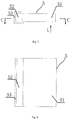
- Fig. 3 is a schematic diagram of a structure principle of the intensity detecting module of the X-ray beam intensity monitoring device as shown in Fig. 1 .
- Fig. 4 is a schematic diagram of a sectional structure principle of a C-C direction of the intensity detecting module as shown in Fig. 3.
- Fig. 3 and Fig. 4 illustrate the working principle of the intensity detecting module in the first embodiment with one of the left detecting module and the right detecting module as an example.
- L represents the incidence direction of the X-ray beam.
- both the left detecting module and the right detecting module are scintillation detecting modules 5.
- Each scintillation detecting module 5 includes a scintillator 51, a photosensor 52, a shielding layer 53 and a reflecting layer (not shown). Wherein, one end of the scintillator 51 is coupled with the photosensor 52 and is located between the photosensor 52 and the working beam.
- the shielding layer 53 is arranged on the periphery of the photosensor 52 to shield the photosensor 52 from the damage of scattered X-rays.
- the shielding layer 53 is preferably made of a heavy metal.
- the reflecting layer is wrapped on a non-coupling surface on which the scintillator 51 is not coupled with the photosensor 52.
- the material of the reflecting layer can be titanium dioxide.
- a respective light sealing structure is arranged in the scintillation detecting modules 5, and the scintillator 51 and the photosensor 52 are arranged in the corresponding sealing structure which is guaranteed to donot leak light.
- the scintillator 51 (i.e., a sensitive volume) of the scintillation detecting module 5 is preferably made of a scintillation crystal.
- the length between the scintillator 51 and the photosensor 52 is preferably large enough to guarantee that the deflection of the fan-shaped beam will not arrive at the position of the photosensor 52.
- the scintillator 51 is preferably vertical to the incidence direction L of the X-ray beam.
- the scintillation detecting module 5 detects the X-ray beam intensity
- the X-rays are irradiated onto the scintillation crystal to emit twinkling light
- the photosensor 52 absorbs the twinkling light to generate an electric signal
- the electric signal output by the photosensor 52 is input to the data processing module for subsequent processing.
- the scintillation detecting module 5 has the advantages of large sensitive medium density and high sensitivity.
- Fig. 5 is a schematic block diagram of the X-ray beam intensity monitoring device of the X-ray inspection system as shown in Fig. 1 .
- the data processing module is coupled with the intensity detecting modules, the detecting signals output by the intensity detecting modules are transmitted to the data processing module together, after the data processing module receives the detecting signals of the intensity detecting modules, the data processing module merges and processes the detecting signals herein and outputs the X-ray beam intensity monitoring signal.
- the data processing module includes an integrating amplifier and a signal conversion device.
- the integrating amplifier is coupled with the intensity detecting modules to receive the detecting signals sent by the intensity detecting modules and output a voltage signal.
- the amplitude of the voltage signal is in direct proportion to the X-ray beam intensity.
- the signal conversion device is coupled with the integrating amplifier to receive the voltage signal of the integrating amplifier and output the X-ray beam intensity monitoring signal.
- the signal conversion device specifically includes a voltage comparator and an analog-digital converter.
- the voltage comparator and the analog-digital converter are independently converted.
- the voltage comparator is coupled with the integrating amplifier to receive the voltage signal of the integrating amplifier and output a level signal to serve as the dose monitoring signal of the X-ray beam.
- a reference voltage of the voltage comparator is determined according to regulated X-ray dose intensity.
- the dose monitoring signal is adopted to control whether to cut off the power supply of the X-ray emitting device or alarm or not.
- the analog-digital converter is coupled with the integrating amplifier to receive the voltage signal of the integrating amplifier and output a digital signal to serve as the brightness correction signal of the X-ray beam.
- the X-ray beam intensity monitoring device of the X-ray inspection system in the first embodiment can simultaneously perform dose monitoring and brightness monitoring, thereby improving the service efficiency of the X-ray beam intensity monitoring device. Moreover, the intensity of the working beam is not influenced by dose monitoring anymore, and the electromagnetic interference from the electron accelerator 1 is avoided. The brightness monitoring is not influenced by the inspected object 4 or the mechanical deformation of the system anymore.
- the second embodiment differs from the first embodiment as follows: in the second embodiment, the scintillation detecting module 5 in the first embodiment is replaced by a gas detecting module 6 to serve as the intensity detecting module. Wherein, the left detecting module and the right detecting module respectively adopt a gas detecting module 6 with the same structure to detect the intensity of the X-ray beam.
- Fig. 6 is a schematic diagram of a structure principle in an overlooking direction of an intensity detecting module of an X-ray beam intensity monitoring device in an X-ray inspection system in the second embodiment of the present invention.
- Fig. 7 is a schematic diagram of a structure principle of the intensity detecting module as shown in Fig. 6 , observed in a direction vertical to an X-ray fan-shaped beam.
- Fig. 6 and Fig. 7 illustrate the working principle of the intensity detecting module in the second embodiment with one of the left detecting module and the right detecting module as an example.
- L represents the incidence direction of the X-ray beam.
- the gas detecting module 6 includes a gas ionization chamber.
- the gas ionization chamber includes two plate electrodes, which are respectively a high-voltage plate electrode 61 and a collection plate electrode 62.
- the two plate electrodes are vertical to the incidence direction L of the X-ray beam.
- the high-voltage plate electrode 61 is connected to high-voltage electricity and is irradiated by the redundant beam, and the collection plate electrode 62 is coupled with the data processing module.
- a working gas 63 is located between the high-voltage plate electrode 61 and the collection plate electrode 62.
- the high-voltage plate electrode 61, the collection plate electrode 62 and the working gas 63 need to be in a sealing structure.
- the advantages of using the gas detecting module 6 as the intensity detecting module lie in that no irradiation damage is caused, a detection area is enlarged easily and the cost is low.
Landscapes
- Physics & Mathematics (AREA)
- Health & Medical Sciences (AREA)
- High Energy & Nuclear Physics (AREA)
- Life Sciences & Earth Sciences (AREA)
- General Physics & Mathematics (AREA)
- Spectroscopy & Molecular Physics (AREA)
- Molecular Biology (AREA)
- Engineering & Computer Science (AREA)
- Toxicology (AREA)
- General Health & Medical Sciences (AREA)
- Multimedia (AREA)
- Signal Processing (AREA)
- General Life Sciences & Earth Sciences (AREA)
- Geophysics (AREA)
- Measurement Of Radiation (AREA)
- Analysing Materials By The Use Of Radiation (AREA)
- X-Ray Techniques (AREA)
- General Engineering & Computer Science (AREA)
Abstract
Description
- The present invention relates to the technical field of X-ray application, and particularly relates to an X-ray beam intensity monitoring device and an X-ray inspection system.
- In an X-ray inspection system, an X-ray emitting device is mainly an electron accelerator or an X-ray tube. The X-ray emitting device and a detector array adopted to receive X-ray are placed on both sides of an inspected object. Under normal circumstances, an X-ray beam emitted by the X-ray emitting device contains both a working beam directly irradiated on the detector array and a redundant beam irradiated on the outside of the detector array.
- The X-ray beam is usually a fan-shaped beam, the fan-shaped beam is perpendicular to the ground, and the width of the working beam in the fan-shaped beam at the detector array is generally required to be approximately equal to the width of the detector array. For this reason, a collimator is often arranged between the X-ray emitting device and the detector array. The collimator is adopted to shield the redundant beam in the X-ray beam. When an object is inspected, the collimator is located between the X-ray emitting device and the inspected object.
- In general, the intensity of the X-ray beam is monitored by means of dose monitoring or brightness monitoring of the X-ray beam. Dose monitoring means monitoring the dose intensity of the X-ray beam, judging whether the dose intensity exceeds a regulated dose value, and if so, and sending a dose monitoring signal to perform such operations as alarming or cutting off the power supply of the X-ray emitting device and the like. Brightness monitoring means collecting a fluctuation change value of the intensity of the X-ray beam within each measurement period and sending a brightness correction signal to correct the value collected by the detector array, so as to obtain more accurate information of the inspected object.
- A dose monitoring device and a brightness monitoring device of the X-ray beam are common in the X-ray inspection system, and the two devices independently exist in the X-ray inspection system under normal conditions.
- The X-ray inspection system and the X-ray beam intensity monitoring device thereof in the prior art will be illustrated below by taking it as an example that the electron accelerator is used as the X-ray emitting device of the X-ray inspection system.
- The dose monitoring device in the prior art includes a detecting module, the detecting module is directly placed at the outlet of the X-ray beam of the electron accelerator in general and is located in a box body of the electron accelerator, X-rays directly penetrate through the sensitive volume of the detecting module and irradiate on the inspected object.
- The monitoring method adopted by the brightness monitoring device in the prior art is to collect a brightness signal by using a redundancy detector at the upper edge region of the fan-shaped beam in the detector array for X-ray inspection and send the brightness correction signal to correct the value collected by the detector array.
- In a process of implementing the present invention, the inventor of the present invention finds that the above prior art has the following disadvantages:
- in the dose monitoring device in the prior art, the X-ray beam intensity is lost because of the necessity of penetrating through the sensitive volume of the detecting module, namely, the detecting sensitive volume intervenes in the X-ray beam intensity and a structure of energy spectrum arriving at the inspected object. Moreover, since the electron accelerator is a heavy current installation, while the detecting module of the dose monitoring device is a weak current instrument, the detecting module is very susceptible to electromagnetic interference of the former, and can only provide average dose information within a certain period of time in general, for example, a few seconds. In the X-ray inspection system, to ensure safety, when the dose of the X-ray beam is larger than a regulated threshold, the power supply of the X-ray emitting device must be cut off as soon as possible, thus the dose monitoring device is required to be reliable and accurate in measurement, but the dose monitoring device in the above prior art is difficult to satisfy this requirement.
- In the brightness monitoring device in the prior art, the redundancy detector of the detector array is susceptible to interference of a reflected signal, mechanical deformation and other factors of the inspected object. Moreover, when the X-ray emitting device is the electron accelerator, the X-ray beam intensity on the "main beam" direction (i.e., the direction of the electron beam) of the X-ray beam is large, the larger the included angle of a position with the "main beam" is, the weaker the X-ray beam intensity is, and the X-ray beam intensity of the region where the redundancy detector is located is generally weak, so that the monitoring result is affected ultimately.
- The purpose of the present invention is to provide an X-ray beam intensity monitoring device and an X-ray inspection system, which can improve the service efficiency of the X-ray beam intensity monitoring device. The other purpose of the present invention is to provide an X-ray inspection system, and the monitoring result of X-ray beam intensity of the X-ray inspection system is more accurate and reliable.
- A first aspect of the present invention provides an X-ray beam intensity monitoring device, including an intensity detecting module and a data processing module, wherein the intensity detecting module is adopted to be irradiated by the X-ray beam and send a detecting signal, the data processing module is coupled with the intensity detecting module to receive the detecting signal and output an X-ray beam intensity monitoring signal, wherein the X-ray beam intensity monitoring signal includes a dose monitoring signal of the X-ray beam and a brightness correction signal of the X-ray beam.
- Further, the X-ray beam intensity monitoring device includes a plurality of intensity detecting modules, and the plurality of intensity detecting modules are coupled with the same data processing module.
- Further, the intensity detecting modules are independently sealed respectively.
- Further, the data processing module includes an integrating amplifier and a signal conversion device, the integrating amplifier is coupled with the intensity detecting module to receive the detecting signal and output a voltage signal, and the signal conversion device is coupled with the integrating amplifier to receive the voltage signal and output the dose monitoring signal and the brightness correction signal.
- Further, the signal conversion device includes a voltage comparator and an analog-digital converter, the voltage comparator is coupled with the integrating amplifier to receive the voltage signal and output a level signal to serve as the dose monitoring signal, and the analog-digital converter is coupled with the integrating amplifier to receive the voltage signal and output a digital signal to serve as the brightness correction signal.
- Further, the intensity detecting module is a scintillation detecting module or a gas detecting module.
- Further, the intensity detecting module is a scintillation detecting module, the scintillation detecting module includes a scintillator, a photosensor and a shielding layer, one end of the scintillator is coupled with the photosensor, and the shielding layer is arranged on the periphery of the photosensor.
- A second aspect of the present invention provides an X-ray inspection system, including an X-ray emitting device, a detector array and an X-ray beam intensity monitoring device, wherein the X-ray beam intensity monitoring device is the X-ray beam intensity monitoring device in any item in the first aspect of the present invention.
- Further, an X-ray beam emitted by the X-ray emitting device includes a working beam irradiated on the detector array and a redundant beam irradiated on the outside of the detector array, and the intensity detecting module of the X-ray beam intensity monitoring device is arranged between the X-ray emitting device and the detector array to be irradiated by the redundant beam and send the detecting signal.
- Further, the X-ray inspection system further includes a collimator, and the intensity detecting module is located between the X-ray emitting device and the collimator.
- According to the X-ray beam intensity monitoring device and the X-ray inspection system provided by the first and second aspect of the present invention, the X-ray beam intensity monitoring device includes the intensity detecting module and the data processing module, the intensity detecting module is adopted to be irradiated by the X-ray beam and send the detecting signal, the data processing module is coupled with the intensity detecting module to receive the detecting signal and output the X-ray beam intensity monitoring signal, wherein the X-ray beam intensity monitoring signal includes the dose monitoring signal of the X-ray beam and the brightness correction signal of the X-ray beam, so that the X-ray beam intensity monitoring device can simultaneously perform dose monitoring and brightness monitoring, which improves the service efficiency of the X-ray beam intensity monitoring device.
- The present invention provides an X-ray inspection system, including an X-ray emitting device, a detector array and an X-ray beam intensity monitoring device, wherein an X-ray beam emitted by the X-ray emitting device includes a working beam irradiated on the detector array and a redundant beam irradiated on the outside of the detector array, the X-ray beam intensity monitoring device includes an intensity detecting module and a data processing module, the intensity detecting module is arranged between the X-ray emitting device and the detector array to be irradiated by the redundant beam and send a detecting signal, and the data processing module is coupled with the intensity detecting module to receive the detecting signal and output an X-ray beam intensity monitoring signal.
- Further, the X-ray inspection system further includes a collimator located between the X-ray emitting device and the detector array, and the intensity detecting module is located between the X-ray emitting device and the collimator.
- Further, the X-ray beam intensity monitoring device includes a plurality of intensity detecting modules which are symmetrically arranged relative to the working beam.
- Further, the X-ray beam is a fan-shaped beam, and the intensity detecting module is located on the sector side of the fan-shaped beam.
- Further, the X-ray beam intensity monitoring signal includes a dose monitoring signal of the X-ray beam and/or a brightness correction signal of the X-ray beam.
- Further, the data processing module includes an integrating amplifier and a signal conversion device, the integrating amplifier is coupled with the intensity detecting module to receive the detecting signal and output a voltage signal, and the signal conversion device is coupled with the integrating amplifier to receive the voltage signal and output the X-ray beam intensity monitoring signal.
- Further, the signal conversion device includes at least one of a voltage comparator and an analog-digital converter, wherein the voltage comparator is coupled with the integrating amplifier to receive the voltage signal and output a level signal to serve as the dose monitoring signal of the X-ray beam, and the analog-digital converter is coupled with the integrating amplifier to receive the voltage signal and output a digital signal to serve as the brightness correction signal of the X-ray beam.
- Further, the intensity detecting module is a scintillation detecting module or a gas detecting module.
- Further, the intensity detecting module is a scintillation detecting module, the scintillation detecting module includes a scintillator, a photosensor and a shielding layer, one end of the scintillator is coupled with the photosensor, the scintillator is located between the photosensor and the working beam to irradiate the redundant beam on the scintillator, and the shielding layer is arranged on the periphery of the photosensor.
- Further, the intensity detecting module is a gas detecting module, the gas detecting module includes a high-voltage plate electrode, a collection plate electrode and a working gas, the high-voltage plate electrode is located between the X-ray emitting device and the collection plate electrode and is vertical to the incidence direction of the X-ray beam to irradiate the redundant beam on the high-voltage plate electrode, and the working gas is located between the high-voltage plate electrode and the collection plate electrode.
- According to the X-ray inspection system provided by the present invention, the X-ray beam intensity monitoring device includes the intensity detecting module and the data processing module, the intensity detecting module is arranged between the emitting device and the detector array to be irradiated by the redundant beam and send the detecting signal, and the data processing module is coupled with the intensity detecting module to receive the detecting signal and output the X-ray beam intensity monitoring signal. The intensity detecting module of the X-ray inspection system adopts the redundant beam of the X-ray beam, and the intensity detecting module is basically free from the influence of the X-ray emitting device and the inspected object, so that the monitoring result of the X-ray beam intensity can be more accurate and reliable. Further, since the intensity detecting module has no influence on the working beam, thereby having no influence on the intensity of the working beam arriving at the inspected object and the detector array.
- Through a detailed description on exemplary embodiments of the present invention with reference to accompanying drawings below, other features and advantages of the present invention will be clear.
- The accompanying drawings illustrated herein are used for providing further understanding of the present invention and constitute a part of the present application, and the exemplary embodiments of the present invention and the illustration thereof are used for explaining the present invention, rather than constituting improper limitations to the present invention. In the accompanying drawings:
-
Fig. 1 is a layout schematic diagram of an X-ray inspection system in the first embodiment of the present invention. -
Fig. 2 is a sectional schematic diagram of a B-B direction of the X-ray inspection system as shown inFig. 1 . -
Fig. 3 is a schematic diagram of a structure principle of an intensity detecting module of an X-ray beam intensity monitoring device in the X-ray inspection system as shown inFig. 1 . -
Fig. 4 is a schematic diagram of a sectional structure principle of a C-C direction of the intensity detecting module as shown inFig. 3 . -
Fig. 5 is a schematic block diagram of the X-ray beam intensity monitoring device of the X-ray inspection system as shown inFig. 1 . -
Fig. 6 is a schematic diagram of a structure principle in an overlooking direction of an intensity detecting module of an X-ray beam intensity monitoring device in an X-ray inspection system in the second embodiment of the present invention. -
Fig. 7 is a schematic diagram of a structure principle of the intensity detecting module as shown inFig. 6 , observed in a direction vertical to an X-ray fan-shaped beam. - In
Fig. 1 to Fig. 7 , marks in the accompanying drawings are respectively as follows: - 1 represents an electron accelerator;
- 2 represents a detector array;
- 3 represents a collimator;
- 4 represents an inspected object;
- 5 represents a scintillation detecting module;
- 51 represents a scintillator;
- 52 represents a photosensor;
- 53 represents a shielding layer;
- 6 represents a gas detecting module;
- 61 represents a high-voltage plate electrode;
- 62 represents a collection plate electrode;
- 63 represents a working gas.
- A clear and complete description of technical solutions in the embodiments of the present invention will be given below, in combination with the accompanying drawings in the embodiments of the present invention. Apparently, the embodiments described below are merely a part, but not all, of the embodiments of the present invention. A description on at least one exemplary embodiment below is actually only illustrative, and cannot be used as any limitation to the present invention or the application or the use thereof. All of the other embodiments, obtained by those of ordinary skill in the art based on the embodiments of the present invention without any creative effort, fall into the protection scope of the present invention.
- Unless otherwise specified, relative arrangement of components and steps, numeric expressions and numerical values described in these embodiments generate no limitation to the scope of the present invention. Meanwhile, it should be understood that, for the convenience of description, the sizes of various components shown in the accompanying drawings are not drawn according to an actual proportional relationship. The technology, methods and equipment known to those of ordinary skill in the relevant art may not be discussed in detail, but the technology, the methods and the equipment should be deemed to be a part of the authorized specification under appropriate circumstances. In all the examples shown and discussed herein, any particular value should be interpreted as being merely an example, not a restriction. Thus, other examples of the exemplary embodiments can have different values. It should be noted that, similar marks and letters represent similar items in the following accompanying drawings, so that once a certain item is defined in an accompanying drawing, the item does not need to be further discussed in the subsequent accompanying drawings.
-
Fig. 1 to Fig. 5 show an X-ray inspection system in the first embodiment of the present invention. -
Fig. 1 is a layout schematic diagram of an X-ray inspection system in the first embodiment of the present invention.Fig. 2 is a sectional schematic diagram of a B-B direction of the X-ray inspection system as shown inFig. 1 . As shown inFig. 1 and Fig. 2 , the X-ray inspection system in the first embodiment includes an X-ray emitting device adopted to emit X-rays, acollimator 3, adetector array 2 used in X-ray inspection and an X-ray beam intensity monitoring device. - Wherein, the X-ray beam intensity monitoring device is adopted to monitor the X-ray beam intensity of the X-ray emitting device. The X-ray beam intensity monitoring device includes an intensity detecting module and a data processing module. The data processing module is coupled with the intensity detecting module to receive the detecting signal sent by the intensity detecting module and output an X-ray beam intensity monitoring signal.
- The X-ray beam intensity monitoring signal includes a dose monitoring signal of the X-ray beam and a brightness correction signal of the X-ray beam. The X-ray beam intensity monitoring device can simultaneously perform dose monitoring and brightness monitoring, thereby improving the service efficiency of the X-ray beam intensity monitoring device.
- An X-ray beam emitted by the X-ray emitting device includes a working beam irradiated on the
detector array 2 and a redundant beam irradiated on the outside of thedetector array 2. The intensity detecting module of the X-ray beam intensity monitoring device is preferably arranged between the emitting device and thedetector array 2 to be irradiated by the redundant beam and send a detecting signal. - The intensity detecting module of the X-ray inspection system adopts the redundant beam of the X-ray beam, and the intensity detecting module is basically free from the influence of the X-ray emitting device and the inspected
object 4, so that the monitoring result of the X-ray beam intensity can be more accurate and reliable. Further, since the intensity detecting module has no influence on the working beam, thereby having no influence on the intensity of the working beam arriving at the inspectedobject 4 and thedetector array 2. - In the first embodiment, the X-ray emitting device is an electron accelerator 1. In other non-shown embodiments, the X-ray emitting device can be other X-ray emitting devices, such as an X-ray tube, etc.
- The
collimator 3 is located between the X-ray emitting device and thedetector array 2. Thecollimator 3 is adopted to shield the redundant beam. When an inspectedobject 4 is inspected, thecollimator 3 is located between the X-ray emitting device and the inspectedobject 4, and the working beam of the X-ray beam irradiates the inspectedobject 4 and thedetector array 2 after passing through thecollimator 3. - When the X-ray inspection system is provided with the
collimator 3, the intensity detecting module is located between the X-ray emitting device and thecollimator 3. Owing to this arrangement, the direct electromagnetic interference from the electron accelerator 1 is avoided, and meanwhile the monitoring result of the X-ray beam intensity will not be influenced by the arrangement of thecollimator 3. - Preferably, the X-ray beam intensity monitoring device includes a plurality of intensity detecting modules which are symmetrically arranged relative to the working beam. By means of the plurality of intensity detecting modules which are symmetrically arranged relative to the working beam, when the X-ray beam emitted by the X-ray emitting device deflects, the detecting signals sent by the intensity detecting modules can compensate each other, so that the monitoring result of the X-ray beam intensity can be more accurate and reliable compared with that when only a single intensity detecting module is arranged. Two intensity detecting modules are specifically arranged in the first embodiment. In other non-shown embodiments, more intensity detecting modules, for example 4, can be arranged.
- In the first embodiment, the working beam is a fan-shaped beam, and the intensity detecting module is located on the sector side of the fan-shaped beam. Owing to this arrangement, the intensity detecting module is located at a "main beam" of the X-ray beam and is closer to the central position of the X-ray beam, so that information of the X-ray beam identify can be provided more effectively.
- As shown in
Fig. 1 and Fig. 2 , the sector of the fan-shaped beam is perpendicular to the ground, one side where the electron accelerator 1 is located is a front side, one side where thedetector array 2 is located is a back side, one intensity detecting module (called a left detecting module and a right detecting module below) is respectively arranged on the left and right sides of the sector of the fan-shaped beam. Wherein, the left detecting module and the right detecting module are placed between the electron accelerator 1 and thecollimator 3 and are adopted to generate the X-ray beam intensity monitoring signal after transmitting the obtained detecting signals to the data processing module for merging and converting. - The left detecting module and the right detecting module are symmetrically arranged on the left and right sides of the sector of the fan-shaped beam and are located at positions capable of being directly irradiated by the redundant beam, so as to monitor the X-ray beam intensity via the redundant beam. The left detecting module and the right detecting module are isolated by a certain gap, and the width of the gap is large enough to guarantee that the working beam can be irradiated within a range required by the width of the
detector array 2 without being influenced. - The left detecting module and the right detecting module are two detectors having symmetrical geometrical shapes and the same structure. In a direction vertical to the sector of the X-ray beam, when an enough sensitive size satisfies left and right deflection of the fan-shaped beam, the coverage widths of the sensitive volumes of the two detectors are still not exceeded. The intensity detecting module can have a plurality of implementation manners.
Fig. 3 is a schematic diagram of a structure principle of the intensity detecting module of the X-ray beam intensity monitoring device as shown inFig. 1 .Fig. 4 is a schematic diagram of a sectional structure principle of a C-C direction of the intensity detecting module as shown inFig. 3. Fig. 3 and Fig. 4 illustrate the working principle of the intensity detecting module in the first embodiment with one of the left detecting module and the right detecting module as an example. InFig. 4 , L represents the incidence direction of the X-ray beam. - As shown in
Fig. 3 and Fig. 4 , in the first embodiment, both the left detecting module and the right detecting module arescintillation detecting modules 5. Eachscintillation detecting module 5 includes ascintillator 51, aphotosensor 52, ashielding layer 53 and a reflecting layer (not shown). Wherein, one end of thescintillator 51 is coupled with thephotosensor 52 and is located between the photosensor 52 and the working beam. Theshielding layer 53 is arranged on the periphery of the photosensor 52 to shield the photosensor 52 from the damage of scattered X-rays. Theshielding layer 53 is preferably made of a heavy metal. The reflecting layer is wrapped on a non-coupling surface on which thescintillator 51 is not coupled with thephotosensor 52. The material of the reflecting layer can be titanium dioxide. In addition, a respective light sealing structure is arranged in thescintillation detecting modules 5, and thescintillator 51 and the photosensor 52 are arranged in the corresponding sealing structure which is guaranteed to donot leak light. - The scintillator 51 (i.e., a sensitive volume) of the
scintillation detecting module 5 is preferably made of a scintillation crystal. The length between thescintillator 51 and thephotosensor 52 is preferably large enough to guarantee that the deflection of the fan-shaped beam will not arrive at the position of thephotosensor 52. Thescintillator 51 is preferably vertical to the incidence direction L of the X-ray beam. - When the
scintillation detecting module 5 detects the X-ray beam intensity, the X-rays are irradiated onto the scintillation crystal to emit twinkling light, thephotosensor 52 absorbs the twinkling light to generate an electric signal, and the electric signal output by thephotosensor 52 is input to the data processing module for subsequent processing. - The
scintillation detecting module 5 has the advantages of large sensitive medium density and high sensitivity. -
Fig. 5 is a schematic block diagram of the X-ray beam intensity monitoring device of the X-ray inspection system as shown inFig. 1 . As shown inFig. 5 , the data processing module is coupled with the intensity detecting modules, the detecting signals output by the intensity detecting modules are transmitted to the data processing module together, after the data processing module receives the detecting signals of the intensity detecting modules, the data processing module merges and processes the detecting signals herein and outputs the X-ray beam intensity monitoring signal. - As shown in
Fig. 5 , the data processing module includes an integrating amplifier and a signal conversion device. Wherein, the integrating amplifier is coupled with the intensity detecting modules to receive the detecting signals sent by the intensity detecting modules and output a voltage signal. The amplitude of the voltage signal is in direct proportion to the X-ray beam intensity. The signal conversion device is coupled with the integrating amplifier to receive the voltage signal of the integrating amplifier and output the X-ray beam intensity monitoring signal. - As shown in
Fig. 5 , in the first embodiment, the signal conversion device specifically includes a voltage comparator and an analog-digital converter. The voltage comparator and the analog-digital converter are independently converted. - The voltage comparator is coupled with the integrating amplifier to receive the voltage signal of the integrating amplifier and output a level signal to serve as the dose monitoring signal of the X-ray beam. A reference voltage of the voltage comparator is determined according to regulated X-ray dose intensity. The dose monitoring signal is adopted to control whether to cut off the power supply of the X-ray emitting device or alarm or not.
- The analog-digital converter is coupled with the integrating amplifier to receive the voltage signal of the integrating amplifier and output a digital signal to serve as the brightness correction signal of the X-ray beam.
- The X-ray beam intensity monitoring device of the X-ray inspection system in the first embodiment can simultaneously perform dose monitoring and brightness monitoring, thereby improving the service efficiency of the X-ray beam intensity monitoring device. Moreover, the intensity of the working beam is not influenced by dose monitoring anymore, and the electromagnetic interference from the electron accelerator 1 is avoided. The brightness monitoring is not influenced by the inspected
object 4 or the mechanical deformation of the system anymore. - The second embodiment differs from the first embodiment as follows: in the second embodiment, the
scintillation detecting module 5 in the first embodiment is replaced by agas detecting module 6 to serve as the intensity detecting module. Wherein, the left detecting module and the right detecting module respectively adopt agas detecting module 6 with the same structure to detect the intensity of the X-ray beam. -
Fig. 6 is a schematic diagram of a structure principle in an overlooking direction of an intensity detecting module of an X-ray beam intensity monitoring device in an X-ray inspection system in the second embodiment of the present invention.Fig. 7 is a schematic diagram of a structure principle of the intensity detecting module as shown inFig. 6 , observed in a direction vertical to an X-ray fan-shaped beam.Fig. 6 andFig. 7 illustrate the working principle of the intensity detecting module in the second embodiment with one of the left detecting module and the right detecting module as an example. InFig. 6 andFig. 7 , L represents the incidence direction of the X-ray beam. - See
Fig. 6 andFig. 7 , thegas detecting module 6 includes a gas ionization chamber. The gas ionization chamber includes two plate electrodes, which are respectively a high-voltage plate electrode 61 and acollection plate electrode 62. The two plate electrodes are vertical to the incidence direction L of the X-ray beam. The high-voltage plate electrode 61 is connected to high-voltage electricity and is irradiated by the redundant beam, and thecollection plate electrode 62 is coupled with the data processing module. A workinggas 63 is located between the high-voltage plate electrode 61 and thecollection plate electrode 62. The high-voltage plate electrode 61, thecollection plate electrode 62 and the workinggas 63 need to be in a sealing structure. - The advantages of using the
gas detecting module 6 as the intensity detecting module lie in that no irradiation damage is caused, a detection area is enlarged easily and the cost is low. - For other non-illustrated portions in the second embodiment, please refer to relevant contents in the first embodiment. The portions will not be repeated redundantly herein.
- Finally, it should be noted that the above-mentioned embodiments are merely used for illustrating the technical solutions of the present invention, rather than limiting them; although the present invention has been described in detail with reference to preferred embodiments, those of ordinary skill in the art should understand that they could still make modifications to the embodiments of the present invention or make equivalent substitutions to a part of technical features; and these modifications or substitutions shall fall into the scope of the technical solutions of the present invention without departing from the spirit of the technical solutions of the present invention.
Claims (13)
- An X-ray beam intensity monitoring device, comprising an intensity detecting module and a data processing module, wherein the intensity detecting module is adopted to be irradiated by the X-ray beam and send a detecting signal, the data processing module is coupled with the intensity detecting module to receive the detecting signal and output an X-ray beam intensity monitoring signal, wherein the X-ray beam intensity monitoring signal comprises a dose monitoring signal of the X-ray beam and a brightness correction signal of the X-ray beam.
- The X-ray beam intensity monitoring device of claim 1, wherein the X-ray beam intensity monitoring device comprises a plurality of intensity detecting modules, and the plurality of intensity detecting modules are coupled with the same data processing module.
- The X-ray beam intensity monitoring device of either of claim 1 or claim 2, in particular claim 2, wherein the intensity detecting modules are independently sealed respectively.
- The X-ray beam intensity monitoring device of any one of the previous claims, wherein the data processing module comprises an integrating amplifier and a signal conversion device, the integrating amplifier is coupled with the intensity detecting module to receive the detecting signal and output a voltage signal, and the signal conversion device is coupled with the integrating amplifier to receive the voltage signal and output the dose monitoring signal and the brightness correction signal.
- The X-ray beam intensity monitoring device of any one of the previous claims, in particular claim 4, wherein the signal conversion device comprises a voltage comparator and an analog-digital converter, the voltage comparator is coupled with the integrating amplifier to receive the voltage signal and output a level signal to serve as the dose monitoring signal, and the analog-digital converter is coupled with the integrating amplifier to receive the voltage signal and output a digital signal to serve as the brightness correction signal.
- The X-ray beam intensity monitoring device of any one of the previous claims, wherein the intensity detecting module is a scintillation detecting module (5) or a gas detecting module (6).
- An X-ray inspection system, comprising an X-ray emitting device, a detector array (2) and an X-ray beam intensity monitoring device, wherein the X-ray beam intensity monitoring device is the X-ray beam intensity monitoring device of any one of the previous claims.
- The X-ray inspection system of claim 7, wherein an X-ray beam emitted by the X-ray emitting device comprises a working beam irradiated on the detector array (2) and a redundant beam irradiated on the outside of the detector array (2), and the intensity detecting module of the X-ray beam intensity monitoring device is arranged between the X-ray emitting device and the detector array (2) to be irradiated by the redundant beam and send the detecting signal.
- The X-ray inspection system of either of claim 7 or claim 8, in particular claim 8, wherein the X-ray inspection system further comprises a collimator (3), and the intensity detecting module is located between the X-ray emitting device and the collimator (3).
- The X-ray inspection system of any one of claims 7 to 9, in particular claim 8, wherein the X-ray beam intensity monitoring device comprises a plurality of intensity detecting modules which are symmetrically arranged relative to the working beam.
- The X-ray inspection system of any one of claims 7 to 10, in particular claim 8, wherein the X-ray beam is a fan-shaped beam, and the intensity detecting module is located on the sector side of the fan-shaped beam.
- The X-ray inspection system of any one of claims 7 to 11, in particular claim 8, wherein the intensity detecting module is a scintillation detecting module (5), the scintillation detecting module (5) comprises a scintillator (51), a photosensor (52) and a shielding layer (53), one end of the scintillator (51) is coupled with the photosensor (52), the scintillator (51) is located between the photosensor (52) and the working beam to irradiate the redundant beam on the scintillator (51), and the shielding layer (53) is arranged on the periphery of the photosensor (52).
- The X-ray inspection system of any one of claims 7 to 12, in particular claim 8, wherein the intensity detecting module is a gas detecting module (6), the gas detecting module (6) comprises a high-voltage plate electrode (61), a collection plate electrode (62) and a working gas (63), the high-voltage plate electrode (61) is located between the X-ray emitting device and the collection plate electrode (62) and is vertical to the incidence direction of the X-ray beam to irradiate the redundant beam on the high-voltage plate electrode (61), and the working gas (63) is located between the high-voltage plate electrode (61) and the collection plate electrode (62).
Priority Applications (1)
| Application Number | Priority Date | Filing Date | Title |
|---|---|---|---|
| PL15203078T PL3040744T3 (en) | 2014-12-31 | 2015-12-30 | X-ray beam intensity monitoring device and x-ray inspection system |
Applications Claiming Priority (2)
| Application Number | Priority Date | Filing Date | Title |
|---|---|---|---|
| CN201410851366.XA CN104516010B (en) | 2014-12-31 | 2014-12-31 | X-ray beam intensity monitoring device and X-ray inspection system |
| CN201410851416.4A CN104515781B (en) | 2014-12-31 | 2014-12-31 | X-ray inspection system |
Publications (2)
| Publication Number | Publication Date |
|---|---|
| EP3040744A1 true EP3040744A1 (en) | 2016-07-06 |
| EP3040744B1 EP3040744B1 (en) | 2020-07-01 |
Family
ID=55077369
Family Applications (1)
| Application Number | Title | Priority Date | Filing Date |
|---|---|---|---|
| EP15203078.9A Active EP3040744B1 (en) | 2014-12-31 | 2015-12-30 | X-ray beam intensity monitoring device and x-ray inspection system |
Country Status (5)
| Country | Link |
|---|---|
| US (1) | US10466372B2 (en) |
| EP (1) | EP3040744B1 (en) |
| BR (1) | BR102015032988B1 (en) |
| PL (1) | PL3040744T3 (en) |
| RU (1) | RU2695099C2 (en) |
Families Citing this family (2)
| Publication number | Priority date | Publication date | Assignee | Title |
|---|---|---|---|---|
| WO2017046289A1 (en) * | 2015-09-18 | 2017-03-23 | Koninklijke Philips N.V. | Processing of a corrected x-ray detector signal |
| CN119958472B (en) * | 2024-12-31 | 2025-11-21 | 深圳中科飞测科技股份有限公司 | An X-ray scattering measurement device, monitoring method and medium |
Citations (2)
| Publication number | Priority date | Publication date | Assignee | Title |
|---|---|---|---|---|
| US4051377A (en) * | 1974-12-23 | 1977-09-27 | U.S. Philips Corporation | Scanning x-ray examination apparatus |
| US7091486B1 (en) * | 2004-09-09 | 2006-08-15 | Kla-Tencor Technologies Corporation | Method and apparatus for beam current fluctuation correction |
Family Cites Families (15)
| Publication number | Priority date | Publication date | Assignee | Title |
|---|---|---|---|---|
| JPS5365774A (en) * | 1976-11-25 | 1978-06-12 | Toshiba Corp | Radiant ray detector |
| JPH09234375A (en) * | 1996-03-01 | 1997-09-09 | Mitsubishi Paper Mills Ltd | Photoreactive harmful material removal material |
| JP2000321220A (en) | 1999-05-14 | 2000-11-24 | Shimadzu Corp | X-ray foreign matter detection method |
| US6751289B2 (en) * | 2000-10-10 | 2004-06-15 | Kabushiki Kaisha Toshiba | X-ray diagnostic apparatus |
| US7062015B2 (en) | 2001-11-17 | 2006-06-13 | Council For The Central Laboratory Of The Research Councils | Method and apparatus for obtaining simultaneously absorption and refraction images by use of a monochromator with integrated radiation detector |
| US6934354B2 (en) * | 2003-05-02 | 2005-08-23 | General Electric Company | Collimator assembly having multi-piece components |
| US7099432B2 (en) | 2003-08-27 | 2006-08-29 | Matsushita Electric Industrial Co., Ltd. | X-ray inspection apparatus and X-ray inspection method |
| JP4825443B2 (en) | 2004-05-11 | 2011-11-30 | 株式会社東芝 | X-ray CT apparatus, radiation detector, and method for reading electrical signal in radiation detector |
| CN103961130B (en) * | 2006-09-25 | 2017-08-15 | 马佐尔机器人有限公司 | So that C-arm system adapts to the method to provide three-dimensional imaging information |
| US7767975B2 (en) | 2007-12-04 | 2010-08-03 | Saint-Gobain Cristaux Et Detecteurs | Ionizing radiation detector |
| CN101261235B (en) | 2008-05-06 | 2010-12-08 | 罗平安 | Crude oil gas fraction and moisture percentage dual energy X ray measurement method |
| CN101937092A (en) | 2009-06-30 | 2011-01-05 | 同方威视技术股份有限公司 | Detector device for radiation imaging |
| RU108859U1 (en) * | 2011-05-31 | 2011-09-27 | Учреждение Российской академии наук Институт радиотехники и электроники им. В.А. Котельникова РАН | DEVICE FOR MEASURING THE INTENSITY OF X-RAY AND GAMMA RADIATION |
| CN204439577U (en) | 2014-12-31 | 2015-07-01 | 清华大学 | X-ray inspection system |
| CN104516010B (en) | 2014-12-31 | 2018-12-11 | 清华大学 | X-ray beam intensity monitoring device and X-ray inspection system |
-
2015
- 2015-12-25 RU RU2015156055A patent/RU2695099C2/en active
- 2015-12-29 US US14/981,953 patent/US10466372B2/en active Active
- 2015-12-30 EP EP15203078.9A patent/EP3040744B1/en active Active
- 2015-12-30 BR BR102015032988-1A patent/BR102015032988B1/en active IP Right Grant
- 2015-12-30 PL PL15203078T patent/PL3040744T3/en unknown
Patent Citations (2)
| Publication number | Priority date | Publication date | Assignee | Title |
|---|---|---|---|---|
| US4051377A (en) * | 1974-12-23 | 1977-09-27 | U.S. Philips Corporation | Scanning x-ray examination apparatus |
| US7091486B1 (en) * | 2004-09-09 | 2006-08-15 | Kla-Tencor Technologies Corporation | Method and apparatus for beam current fluctuation correction |
Also Published As
| Publication number | Publication date |
|---|---|
| RU2015156055A (en) | 2017-06-28 |
| RU2015156055A3 (en) | 2019-01-31 |
| RU2695099C2 (en) | 2019-07-19 |
| BR102015032988B1 (en) | 2021-01-12 |
| BR102015032988A2 (en) | 2016-09-27 |
| US10466372B2 (en) | 2019-11-05 |
| EP3040744B1 (en) | 2020-07-01 |
| US20160187502A1 (en) | 2016-06-30 |
| PL3040744T3 (en) | 2021-02-08 |
Similar Documents
| Publication | Publication Date | Title |
|---|---|---|
| CN104515781B (en) | X-ray inspection system | |
| US7386093B2 (en) | Method and an apparatus for liquid safety-detection with a radiation source | |
| US8993977B2 (en) | Detector and a method for simultaneously detecting both gamma rays and neutron using the same | |
| US20050105687A1 (en) | Computer tomograph comprising energy discriminating detectors | |
| US7684541B2 (en) | System and method capable of simultaneous radiographic examination and radioactive material inspection | |
| TWI515451B (en) | Neutron beam detection device and neutron capture therapy device | |
| SE9704015D0 (en) | A method and a device for planer beam radiography and a radiation detector | |
| US10197700B2 (en) | Method for autonomous self-blanking by radiation portal monitors to minimize the interference from pulsed X-rays radiation | |
| GB2545947A (en) | Dual-energy detection apparatus, system and method | |
| CN113568030B (en) | Detector components and radiation monitoring equipment | |
| US10466372B2 (en) | X-ray beam intensity monitoring device and X-ray inspection | |
| US20150221406A1 (en) | X-ray radiation detector, ct system and related method | |
| CN104516010A (en) | X-ray beam intensity monitoring device and X-ray inspection system | |
| SE9904834L (en) | Method and apparatus for radiography and radiation detector | |
| CN204439577U (en) | X-ray inspection system | |
| US9464997B2 (en) | Methods and apparatuses for measuring effective atomic number of an object | |
| CN204439843U (en) | X-ray beam intensity of flow supervising device and X-ray inspection system | |
| CN117190928A (en) | An ore material layer thickness detection system based on dual-energy X-rays | |
| JP7084758B2 (en) | Neutron beam detector and anomaly detection method for neutron beam detector | |
| HK1209489A1 (en) | X-ray beam intensity monitoring device and x-ray inspection system | |
| JP2011112623A (en) | Two-stage x-ray detector | |
| HK1209489B (en) | X-ray beam intensity monitoring device and x-ray inspection system | |
| JP6875265B2 (en) | Neutron beam detector | |
| CN114096889B (en) | Radiation beam detection device | |
| WO2016070858A1 (en) | Method of coincidence imaging using secondary electrons and a device for executing this method |
Legal Events
| Date | Code | Title | Description |
|---|---|---|---|
| PUAI | Public reference made under article 153(3) epc to a published international application that has entered the european phase |
Free format text: ORIGINAL CODE: 0009012 |
|
| AK | Designated contracting states |
Kind code of ref document: A1 Designated state(s): AL AT BE BG CH CY CZ DE DK EE ES FI FR GB GR HR HU IE IS IT LI LT LU LV MC MK MT NL NO PL PT RO RS SE SI SK SM TR |
|
| AX | Request for extension of the european patent |
Extension state: BA ME |
|
| STAA | Information on the status of an ep patent application or granted ep patent |
Free format text: STATUS: REQUEST FOR EXAMINATION WAS MADE |
|
| 17P | Request for examination filed |
Effective date: 20170105 |
|
| RBV | Designated contracting states (corrected) |
Designated state(s): AL AT BE BG CH CY CZ DE DK EE ES FI FR GB GR HR HU IE IS IT LI LT LU LV MC MK MT NL NO PL PT RO RS SE SI SK SM TR |
|
| STAA | Information on the status of an ep patent application or granted ep patent |
Free format text: STATUS: EXAMINATION IS IN PROGRESS |
|
| 17Q | First examination report despatched |
Effective date: 20171222 |
|
| GRAP | Despatch of communication of intention to grant a patent |
Free format text: ORIGINAL CODE: EPIDOSNIGR1 |
|
| STAA | Information on the status of an ep patent application or granted ep patent |
Free format text: STATUS: GRANT OF PATENT IS INTENDED |
|
| INTG | Intention to grant announced |
Effective date: 20190227 |
|
| RIN1 | Information on inventor provided before grant (corrected) |
Inventor name: LIU, YAOHONG Inventor name: ZHAO, ZIRAN Inventor name: LI, YUANJING Inventor name: LI, YULAN Inventor name: ZHANG, QINGJUN Inventor name: HE, HUISHAO Inventor name: KANG, KEJUN Inventor name: ZHU, WEIBIN Inventor name: ZHAO, XIAOLIN Inventor name: LIU, YINONG Inventor name: LI, SHUWEI |
|
| GRAJ | Information related to disapproval of communication of intention to grant by the applicant or resumption of examination proceedings by the epo deleted |
Free format text: ORIGINAL CODE: EPIDOSDIGR1 |
|
| STAA | Information on the status of an ep patent application or granted ep patent |
Free format text: STATUS: EXAMINATION IS IN PROGRESS |
|
| INTC | Intention to grant announced (deleted) | ||
| GRAJ | Information related to disapproval of communication of intention to grant by the applicant or resumption of examination proceedings by the epo deleted |
Free format text: ORIGINAL CODE: EPIDOSDIGR1 |
|
| STAA | Information on the status of an ep patent application or granted ep patent |
Free format text: STATUS: GRANT OF PATENT IS INTENDED |
|
| GRAP | Despatch of communication of intention to grant a patent |
Free format text: ORIGINAL CODE: EPIDOSNIGR1 |
|
| INTG | Intention to grant announced |
Effective date: 20200113 |
|
| RIN1 | Information on inventor provided before grant (corrected) |
Inventor name: KANG, KEJUN Inventor name: LIU, YAOHONG Inventor name: LIU, YINONG Inventor name: LI, YUANJING Inventor name: ZHU, WEIBIN Inventor name: ZHANG, QINGJUN Inventor name: LI, YULAN Inventor name: LI, SHUWEI Inventor name: ZHAO, ZIRAN Inventor name: ZHAO, XIAOLIN Inventor name: HE, HUISHAO |
|
| GRAS | Grant fee paid |
Free format text: ORIGINAL CODE: EPIDOSNIGR3 |
|
| GRAA | (expected) grant |
Free format text: ORIGINAL CODE: 0009210 |
|
| STAA | Information on the status of an ep patent application or granted ep patent |
Free format text: STATUS: THE PATENT HAS BEEN GRANTED |
|
| AK | Designated contracting states |
Kind code of ref document: B1 Designated state(s): AL AT BE BG CH CY CZ DE DK EE ES FI FR GB GR HR HU IE IS IT LI LT LU LV MC MK MT NL NO PL PT RO RS SE SI SK SM TR |
|
| REG | Reference to a national code |
Ref country code: AT Ref legal event code: REF Ref document number: 1286687 Country of ref document: AT Kind code of ref document: T Effective date: 20200715 Ref country code: CH Ref legal event code: EP |
|
| REG | Reference to a national code |
Ref country code: IE Ref legal event code: FG4D |
|
| REG | Reference to a national code |
Ref country code: DE Ref legal event code: R096 Ref document number: 602015055013 Country of ref document: DE |
|
| REG | Reference to a national code |
Ref country code: NL Ref legal event code: FP |
|
| REG | Reference to a national code |
Ref country code: LT Ref legal event code: MG4D |
|
| PG25 | Lapsed in a contracting state [announced via postgrant information from national office to epo] |
Ref country code: BG Free format text: LAPSE BECAUSE OF FAILURE TO SUBMIT A TRANSLATION OF THE DESCRIPTION OR TO PAY THE FEE WITHIN THE PRESCRIBED TIME-LIMIT Effective date: 20201001 |
|
| REG | Reference to a national code |
Ref country code: AT Ref legal event code: MK05 Ref document number: 1286687 Country of ref document: AT Kind code of ref document: T Effective date: 20200701 |
|
| PG25 | Lapsed in a contracting state [announced via postgrant information from national office to epo] |
Ref country code: HR Free format text: LAPSE BECAUSE OF FAILURE TO SUBMIT A TRANSLATION OF THE DESCRIPTION OR TO PAY THE FEE WITHIN THE PRESCRIBED TIME-LIMIT Effective date: 20200701 Ref country code: LT Free format text: LAPSE BECAUSE OF FAILURE TO SUBMIT A TRANSLATION OF THE DESCRIPTION OR TO PAY THE FEE WITHIN THE PRESCRIBED TIME-LIMIT Effective date: 20200701 Ref country code: ES Free format text: LAPSE BECAUSE OF FAILURE TO SUBMIT A TRANSLATION OF THE DESCRIPTION OR TO PAY THE FEE WITHIN THE PRESCRIBED TIME-LIMIT Effective date: 20200701 Ref country code: CZ Free format text: LAPSE BECAUSE OF FAILURE TO SUBMIT A TRANSLATION OF THE DESCRIPTION OR TO PAY THE FEE WITHIN THE PRESCRIBED TIME-LIMIT Effective date: 20200701 Ref country code: NO Free format text: LAPSE BECAUSE OF FAILURE TO SUBMIT A TRANSLATION OF THE DESCRIPTION OR TO PAY THE FEE WITHIN THE PRESCRIBED TIME-LIMIT Effective date: 20201001 Ref country code: GR Free format text: LAPSE BECAUSE OF FAILURE TO SUBMIT A TRANSLATION OF THE DESCRIPTION OR TO PAY THE FEE WITHIN THE PRESCRIBED TIME-LIMIT Effective date: 20201002 Ref country code: FI Free format text: LAPSE BECAUSE OF FAILURE TO SUBMIT A TRANSLATION OF THE DESCRIPTION OR TO PAY THE FEE WITHIN THE PRESCRIBED TIME-LIMIT Effective date: 20200701 Ref country code: SE Free format text: LAPSE BECAUSE OF FAILURE TO SUBMIT A TRANSLATION OF THE DESCRIPTION OR TO PAY THE FEE WITHIN THE PRESCRIBED TIME-LIMIT Effective date: 20200701 Ref country code: PT Free format text: LAPSE BECAUSE OF FAILURE TO SUBMIT A TRANSLATION OF THE DESCRIPTION OR TO PAY THE FEE WITHIN THE PRESCRIBED TIME-LIMIT Effective date: 20201102 Ref country code: AT Free format text: LAPSE BECAUSE OF FAILURE TO SUBMIT A TRANSLATION OF THE DESCRIPTION OR TO PAY THE FEE WITHIN THE PRESCRIBED TIME-LIMIT Effective date: 20200701 |
|
| PG25 | Lapsed in a contracting state [announced via postgrant information from national office to epo] |
Ref country code: IS Free format text: LAPSE BECAUSE OF FAILURE TO SUBMIT A TRANSLATION OF THE DESCRIPTION OR TO PAY THE FEE WITHIN THE PRESCRIBED TIME-LIMIT Effective date: 20201101 Ref country code: RS Free format text: LAPSE BECAUSE OF FAILURE TO SUBMIT A TRANSLATION OF THE DESCRIPTION OR TO PAY THE FEE WITHIN THE PRESCRIBED TIME-LIMIT Effective date: 20200701 Ref country code: LV Free format text: LAPSE BECAUSE OF FAILURE TO SUBMIT A TRANSLATION OF THE DESCRIPTION OR TO PAY THE FEE WITHIN THE PRESCRIBED TIME-LIMIT Effective date: 20200701 |
|
| REG | Reference to a national code |
Ref country code: DE Ref legal event code: R097 Ref document number: 602015055013 Country of ref document: DE |
|
| PG25 | Lapsed in a contracting state [announced via postgrant information from national office to epo] |
Ref country code: SM Free format text: LAPSE BECAUSE OF FAILURE TO SUBMIT A TRANSLATION OF THE DESCRIPTION OR TO PAY THE FEE WITHIN THE PRESCRIBED TIME-LIMIT Effective date: 20200701 Ref country code: RO Free format text: LAPSE BECAUSE OF FAILURE TO SUBMIT A TRANSLATION OF THE DESCRIPTION OR TO PAY THE FEE WITHIN THE PRESCRIBED TIME-LIMIT Effective date: 20200701 Ref country code: EE Free format text: LAPSE BECAUSE OF FAILURE TO SUBMIT A TRANSLATION OF THE DESCRIPTION OR TO PAY THE FEE WITHIN THE PRESCRIBED TIME-LIMIT Effective date: 20200701 Ref country code: DK Free format text: LAPSE BECAUSE OF FAILURE TO SUBMIT A TRANSLATION OF THE DESCRIPTION OR TO PAY THE FEE WITHIN THE PRESCRIBED TIME-LIMIT Effective date: 20200701 Ref country code: IT Free format text: LAPSE BECAUSE OF FAILURE TO SUBMIT A TRANSLATION OF THE DESCRIPTION OR TO PAY THE FEE WITHIN THE PRESCRIBED TIME-LIMIT Effective date: 20200701 |
|
| PLBE | No opposition filed within time limit |
Free format text: ORIGINAL CODE: 0009261 |
|
| STAA | Information on the status of an ep patent application or granted ep patent |
Free format text: STATUS: NO OPPOSITION FILED WITHIN TIME LIMIT |
|
| PG25 | Lapsed in a contracting state [announced via postgrant information from national office to epo] |
Ref country code: AL Free format text: LAPSE BECAUSE OF FAILURE TO SUBMIT A TRANSLATION OF THE DESCRIPTION OR TO PAY THE FEE WITHIN THE PRESCRIBED TIME-LIMIT Effective date: 20200701 |
|
| 26N | No opposition filed |
Effective date: 20210406 |
|
| PG25 | Lapsed in a contracting state [announced via postgrant information from national office to epo] |
Ref country code: SK Free format text: LAPSE BECAUSE OF FAILURE TO SUBMIT A TRANSLATION OF THE DESCRIPTION OR TO PAY THE FEE WITHIN THE PRESCRIBED TIME-LIMIT Effective date: 20200701 |
|
| REG | Reference to a national code |
Ref country code: CH Ref legal event code: PL |
|
| PG25 | Lapsed in a contracting state [announced via postgrant information from national office to epo] |
Ref country code: SI Free format text: LAPSE BECAUSE OF FAILURE TO SUBMIT A TRANSLATION OF THE DESCRIPTION OR TO PAY THE FEE WITHIN THE PRESCRIBED TIME-LIMIT Effective date: 20200701 Ref country code: MC Free format text: LAPSE BECAUSE OF FAILURE TO SUBMIT A TRANSLATION OF THE DESCRIPTION OR TO PAY THE FEE WITHIN THE PRESCRIBED TIME-LIMIT Effective date: 20200701 |
|
| REG | Reference to a national code |
Ref country code: BE Ref legal event code: MM Effective date: 20201231 |
|
| PG25 | Lapsed in a contracting state [announced via postgrant information from national office to epo] |
Ref country code: LU Free format text: LAPSE BECAUSE OF NON-PAYMENT OF DUE FEES Effective date: 20201230 Ref country code: IE Free format text: LAPSE BECAUSE OF NON-PAYMENT OF DUE FEES Effective date: 20201230 |
|
| PG25 | Lapsed in a contracting state [announced via postgrant information from national office to epo] |
Ref country code: LI Free format text: LAPSE BECAUSE OF NON-PAYMENT OF DUE FEES Effective date: 20201231 Ref country code: CH Free format text: LAPSE BECAUSE OF NON-PAYMENT OF DUE FEES Effective date: 20201231 |
|
| PG25 | Lapsed in a contracting state [announced via postgrant information from national office to epo] |
Ref country code: TR Free format text: LAPSE BECAUSE OF FAILURE TO SUBMIT A TRANSLATION OF THE DESCRIPTION OR TO PAY THE FEE WITHIN THE PRESCRIBED TIME-LIMIT Effective date: 20200701 Ref country code: MT Free format text: LAPSE BECAUSE OF FAILURE TO SUBMIT A TRANSLATION OF THE DESCRIPTION OR TO PAY THE FEE WITHIN THE PRESCRIBED TIME-LIMIT Effective date: 20200701 Ref country code: CY Free format text: LAPSE BECAUSE OF FAILURE TO SUBMIT A TRANSLATION OF THE DESCRIPTION OR TO PAY THE FEE WITHIN THE PRESCRIBED TIME-LIMIT Effective date: 20200701 |
|
| PG25 | Lapsed in a contracting state [announced via postgrant information from national office to epo] |
Ref country code: MK Free format text: LAPSE BECAUSE OF FAILURE TO SUBMIT A TRANSLATION OF THE DESCRIPTION OR TO PAY THE FEE WITHIN THE PRESCRIBED TIME-LIMIT Effective date: 20200701 |
|
| PG25 | Lapsed in a contracting state [announced via postgrant information from national office to epo] |
Ref country code: BE Free format text: LAPSE BECAUSE OF NON-PAYMENT OF DUE FEES Effective date: 20201231 |
|
| P01 | Opt-out of the competence of the unified patent court (upc) registered |
Effective date: 20230528 |
|
| PGFP | Annual fee paid to national office [announced via postgrant information from national office to epo] |
Ref country code: NL Payment date: 20251031 Year of fee payment: 11 |
|
| PGFP | Annual fee paid to national office [announced via postgrant information from national office to epo] |
Ref country code: GB Payment date: 20251104 Year of fee payment: 11 |
|
| PGFP | Annual fee paid to national office [announced via postgrant information from national office to epo] |
Ref country code: FR Payment date: 20251125 Year of fee payment: 11 |
|
| PGFP | Annual fee paid to national office [announced via postgrant information from national office to epo] |
Ref country code: PL Payment date: 20251219 Year of fee payment: 11 |
|
| PGFP | Annual fee paid to national office [announced via postgrant information from national office to epo] |
Ref country code: DE Payment date: 20251222 Year of fee payment: 11 |