EP3040658B1 - Home appliance with a power-consumption output device - Google Patents
Home appliance with a power-consumption output device Download PDFInfo
- Publication number
- EP3040658B1 EP3040658B1 EP14839818.3A EP14839818A EP3040658B1 EP 3040658 B1 EP3040658 B1 EP 3040658B1 EP 14839818 A EP14839818 A EP 14839818A EP 3040658 B1 EP3040658 B1 EP 3040658B1
- Authority
- EP
- European Patent Office
- Prior art keywords
- power consumption
- reference value
- refrigerator
- home appliance
- unit
- Prior art date
- Legal status (The legal status is an assumption and is not a legal conclusion. Google has not performed a legal analysis and makes no representation as to the accuracy of the status listed.)
- Active
Links
- 230000001186 cumulative effect Effects 0.000 claims description 20
- 230000002093 peripheral effect Effects 0.000 claims description 8
- 235000013305 food Nutrition 0.000 claims description 5
- XLYOFNOQVPJJNP-UHFFFAOYSA-N water Chemical compound O XLYOFNOQVPJJNP-UHFFFAOYSA-N 0.000 description 21
- 238000004891 communication Methods 0.000 description 17
- 238000005057 refrigeration Methods 0.000 description 14
- 238000001816 cooling Methods 0.000 description 7
- 238000004458 analytical method Methods 0.000 description 4
- 230000003287 optical effect Effects 0.000 description 4
- 230000005611 electricity Effects 0.000 description 3
- 235000013311 vegetables Nutrition 0.000 description 3
- 238000009825 accumulation Methods 0.000 description 2
- 238000004364 calculation method Methods 0.000 description 2
- 238000001514 detection method Methods 0.000 description 2
- 238000000034 method Methods 0.000 description 2
- 230000002159 abnormal effect Effects 0.000 description 1
- 238000005516 engineering process Methods 0.000 description 1
- 239000004973 liquid crystal related substance Substances 0.000 description 1
- 230000004048 modification Effects 0.000 description 1
- 238000012986 modification Methods 0.000 description 1
- 229940021317 other blood product in atc Drugs 0.000 description 1
- 210000002381 plasma Anatomy 0.000 description 1
- 230000004044 response Effects 0.000 description 1
- 239000008400 supply water Substances 0.000 description 1
- 230000000007 visual effect Effects 0.000 description 1
- 238000005406 washing Methods 0.000 description 1
Images


Classifications
-
- F—MECHANICAL ENGINEERING; LIGHTING; HEATING; WEAPONS; BLASTING
- F25—REFRIGERATION OR COOLING; COMBINED HEATING AND REFRIGERATION SYSTEMS; HEAT PUMP SYSTEMS; MANUFACTURE OR STORAGE OF ICE; LIQUEFACTION SOLIDIFICATION OF GASES
- F25D—REFRIGERATORS; COLD ROOMS; ICE-BOXES; COOLING OR FREEZING APPARATUS NOT OTHERWISE PROVIDED FOR
- F25D29/00—Arrangement or mounting of control or safety devices
-
- G—PHYSICS
- G05—CONTROLLING; REGULATING
- G05B—CONTROL OR REGULATING SYSTEMS IN GENERAL; FUNCTIONAL ELEMENTS OF SUCH SYSTEMS; MONITORING OR TESTING ARRANGEMENTS FOR SUCH SYSTEMS OR ELEMENTS
- G05B15/00—Systems controlled by a computer
- G05B15/02—Systems controlled by a computer electric
-
- G—PHYSICS
- G05—CONTROLLING; REGULATING
- G05F—SYSTEMS FOR REGULATING ELECTRIC OR MAGNETIC VARIABLES
- G05F1/00—Automatic systems in which deviations of an electric quantity from one or more predetermined values are detected at the output of the system and fed back to a device within the system to restore the detected quantity to its predetermined value or values, i.e. retroactive systems
- G05F1/66—Regulating electric power
-
- H—ELECTRICITY
- H02—GENERATION; CONVERSION OR DISTRIBUTION OF ELECTRIC POWER
- H02J—CIRCUIT ARRANGEMENTS OR SYSTEMS FOR SUPPLYING OR DISTRIBUTING ELECTRIC POWER; SYSTEMS FOR STORING ELECTRIC ENERGY
- H02J13/00—Circuit arrangements for providing remote indication of network conditions, e.g. an instantaneous record of the open or closed condition of each circuitbreaker in the network; Circuit arrangements for providing remote control of switching means in a power distribution network, e.g. switching in and out of current consumers by using a pulse code signal carried by the network
- H02J13/00002—Circuit arrangements for providing remote indication of network conditions, e.g. an instantaneous record of the open or closed condition of each circuitbreaker in the network; Circuit arrangements for providing remote control of switching means in a power distribution network, e.g. switching in and out of current consumers by using a pulse code signal carried by the network characterised by monitoring
-
- H—ELECTRICITY
- H02—GENERATION; CONVERSION OR DISTRIBUTION OF ELECTRIC POWER
- H02J—CIRCUIT ARRANGEMENTS OR SYSTEMS FOR SUPPLYING OR DISTRIBUTING ELECTRIC POWER; SYSTEMS FOR STORING ELECTRIC ENERGY
- H02J13/00—Circuit arrangements for providing remote indication of network conditions, e.g. an instantaneous record of the open or closed condition of each circuitbreaker in the network; Circuit arrangements for providing remote control of switching means in a power distribution network, e.g. switching in and out of current consumers by using a pulse code signal carried by the network
- H02J13/00004—Circuit arrangements for providing remote indication of network conditions, e.g. an instantaneous record of the open or closed condition of each circuitbreaker in the network; Circuit arrangements for providing remote control of switching means in a power distribution network, e.g. switching in and out of current consumers by using a pulse code signal carried by the network characterised by the power network being locally controlled
-
- F—MECHANICAL ENGINEERING; LIGHTING; HEATING; WEAPONS; BLASTING
- F25—REFRIGERATION OR COOLING; COMBINED HEATING AND REFRIGERATION SYSTEMS; HEAT PUMP SYSTEMS; MANUFACTURE OR STORAGE OF ICE; LIQUEFACTION SOLIDIFICATION OF GASES
- F25B—REFRIGERATION MACHINES, PLANTS OR SYSTEMS; COMBINED HEATING AND REFRIGERATION SYSTEMS; HEAT PUMP SYSTEMS
- F25B2600/00—Control issues
- F25B2600/07—Remote controls
-
- F—MECHANICAL ENGINEERING; LIGHTING; HEATING; WEAPONS; BLASTING
- F25—REFRIGERATION OR COOLING; COMBINED HEATING AND REFRIGERATION SYSTEMS; HEAT PUMP SYSTEMS; MANUFACTURE OR STORAGE OF ICE; LIQUEFACTION SOLIDIFICATION OF GASES
- F25B—REFRIGERATION MACHINES, PLANTS OR SYSTEMS; COMBINED HEATING AND REFRIGERATION SYSTEMS; HEAT PUMP SYSTEMS
- F25B2700/00—Sensing or detecting of parameters; Sensors therefor
- F25B2700/15—Power, e.g. by voltage or current
-
- F—MECHANICAL ENGINEERING; LIGHTING; HEATING; WEAPONS; BLASTING
- F25—REFRIGERATION OR COOLING; COMBINED HEATING AND REFRIGERATION SYSTEMS; HEAT PUMP SYSTEMS; MANUFACTURE OR STORAGE OF ICE; LIQUEFACTION SOLIDIFICATION OF GASES
- F25D—REFRIGERATORS; COLD ROOMS; ICE-BOXES; COOLING OR FREEZING APPARATUS NOT OTHERWISE PROVIDED FOR
- F25D2700/00—Means for sensing or measuring; Sensors therefor
- F25D2700/02—Sensors detecting door opening
-
- F—MECHANICAL ENGINEERING; LIGHTING; HEATING; WEAPONS; BLASTING
- F25—REFRIGERATION OR COOLING; COMBINED HEATING AND REFRIGERATION SYSTEMS; HEAT PUMP SYSTEMS; MANUFACTURE OR STORAGE OF ICE; LIQUEFACTION SOLIDIFICATION OF GASES
- F25D—REFRIGERATORS; COLD ROOMS; ICE-BOXES; COOLING OR FREEZING APPARATUS NOT OTHERWISE PROVIDED FOR
- F25D2700/00—Means for sensing or measuring; Sensors therefor
- F25D2700/06—Sensors detecting the presence of a product
-
- F—MECHANICAL ENGINEERING; LIGHTING; HEATING; WEAPONS; BLASTING
- F25—REFRIGERATION OR COOLING; COMBINED HEATING AND REFRIGERATION SYSTEMS; HEAT PUMP SYSTEMS; MANUFACTURE OR STORAGE OF ICE; LIQUEFACTION SOLIDIFICATION OF GASES
- F25D—REFRIGERATORS; COLD ROOMS; ICE-BOXES; COOLING OR FREEZING APPARATUS NOT OTHERWISE PROVIDED FOR
- F25D2700/00—Means for sensing or measuring; Sensors therefor
- F25D2700/14—Sensors measuring the temperature outside the refrigerator or freezer
-
- G—PHYSICS
- G01—MEASURING; TESTING
- G01D—MEASURING NOT SPECIALLY ADAPTED FOR A SPECIFIC VARIABLE; ARRANGEMENTS FOR MEASURING TWO OR MORE VARIABLES NOT COVERED IN A SINGLE OTHER SUBCLASS; TARIFF METERING APPARATUS; MEASURING OR TESTING NOT OTHERWISE PROVIDED FOR
- G01D2204/00—Indexing scheme relating to details of tariff-metering apparatus
- G01D2204/10—Analysing; Displaying
- G01D2204/14—Displaying of utility usage with respect to time, e.g. for monitoring evolution of usage or with respect to weather conditions
-
- G—PHYSICS
- G01—MEASURING; TESTING
- G01D—MEASURING NOT SPECIALLY ADAPTED FOR A SPECIFIC VARIABLE; ARRANGEMENTS FOR MEASURING TWO OR MORE VARIABLES NOT COVERED IN A SINGLE OTHER SUBCLASS; TARIFF METERING APPARATUS; MEASURING OR TESTING NOT OTHERWISE PROVIDED FOR
- G01D4/00—Tariff metering apparatus
- G01D4/02—Details
-
- H—ELECTRICITY
- H02—GENERATION; CONVERSION OR DISTRIBUTION OF ELECTRIC POWER
- H02J—CIRCUIT ARRANGEMENTS OR SYSTEMS FOR SUPPLYING OR DISTRIBUTING ELECTRIC POWER; SYSTEMS FOR STORING ELECTRIC ENERGY
- H02J13/00—Circuit arrangements for providing remote indication of network conditions, e.g. an instantaneous record of the open or closed condition of each circuitbreaker in the network; Circuit arrangements for providing remote control of switching means in a power distribution network, e.g. switching in and out of current consumers by using a pulse code signal carried by the network
- H02J13/00006—Circuit arrangements for providing remote indication of network conditions, e.g. an instantaneous record of the open or closed condition of each circuitbreaker in the network; Circuit arrangements for providing remote control of switching means in a power distribution network, e.g. switching in and out of current consumers by using a pulse code signal carried by the network characterised by information or instructions transport means between the monitoring, controlling or managing units and monitored, controlled or operated power network element or electrical equipment
- H02J13/00022—Circuit arrangements for providing remote indication of network conditions, e.g. an instantaneous record of the open or closed condition of each circuitbreaker in the network; Circuit arrangements for providing remote control of switching means in a power distribution network, e.g. switching in and out of current consumers by using a pulse code signal carried by the network characterised by information or instructions transport means between the monitoring, controlling or managing units and monitored, controlled or operated power network element or electrical equipment using wireless data transmission
- H02J13/00024—Circuit arrangements for providing remote indication of network conditions, e.g. an instantaneous record of the open or closed condition of each circuitbreaker in the network; Circuit arrangements for providing remote control of switching means in a power distribution network, e.g. switching in and out of current consumers by using a pulse code signal carried by the network characterised by information or instructions transport means between the monitoring, controlling or managing units and monitored, controlled or operated power network element or electrical equipment using wireless data transmission by means of mobile telephony
-
- H—ELECTRICITY
- H02—GENERATION; CONVERSION OR DISTRIBUTION OF ELECTRIC POWER
- H02J—CIRCUIT ARRANGEMENTS OR SYSTEMS FOR SUPPLYING OR DISTRIBUTING ELECTRIC POWER; SYSTEMS FOR STORING ELECTRIC ENERGY
- H02J13/00—Circuit arrangements for providing remote indication of network conditions, e.g. an instantaneous record of the open or closed condition of each circuitbreaker in the network; Circuit arrangements for providing remote control of switching means in a power distribution network, e.g. switching in and out of current consumers by using a pulse code signal carried by the network
- H02J13/00006—Circuit arrangements for providing remote indication of network conditions, e.g. an instantaneous record of the open or closed condition of each circuitbreaker in the network; Circuit arrangements for providing remote control of switching means in a power distribution network, e.g. switching in and out of current consumers by using a pulse code signal carried by the network characterised by information or instructions transport means between the monitoring, controlling or managing units and monitored, controlled or operated power network element or electrical equipment
- H02J13/00022—Circuit arrangements for providing remote indication of network conditions, e.g. an instantaneous record of the open or closed condition of each circuitbreaker in the network; Circuit arrangements for providing remote control of switching means in a power distribution network, e.g. switching in and out of current consumers by using a pulse code signal carried by the network characterised by information or instructions transport means between the monitoring, controlling or managing units and monitored, controlled or operated power network element or electrical equipment using wireless data transmission
- H02J13/00026—Circuit arrangements for providing remote indication of network conditions, e.g. an instantaneous record of the open or closed condition of each circuitbreaker in the network; Circuit arrangements for providing remote control of switching means in a power distribution network, e.g. switching in and out of current consumers by using a pulse code signal carried by the network characterised by information or instructions transport means between the monitoring, controlling or managing units and monitored, controlled or operated power network element or electrical equipment using wireless data transmission involving a local wireless network, e.g. Wi-Fi, ZigBee or Bluetooth
-
- H—ELECTRICITY
- H02—GENERATION; CONVERSION OR DISTRIBUTION OF ELECTRIC POWER
- H02J—CIRCUIT ARRANGEMENTS OR SYSTEMS FOR SUPPLYING OR DISTRIBUTING ELECTRIC POWER; SYSTEMS FOR STORING ELECTRIC ENERGY
- H02J2310/00—The network for supplying or distributing electric power characterised by its spatial reach or by the load
- H02J2310/10—The network having a local or delimited stationary reach
- H02J2310/12—The local stationary network supplying a household or a building
-
- Y—GENERAL TAGGING OF NEW TECHNOLOGICAL DEVELOPMENTS; GENERAL TAGGING OF CROSS-SECTIONAL TECHNOLOGIES SPANNING OVER SEVERAL SECTIONS OF THE IPC; TECHNICAL SUBJECTS COVERED BY FORMER USPC CROSS-REFERENCE ART COLLECTIONS [XRACs] AND DIGESTS
- Y02—TECHNOLOGIES OR APPLICATIONS FOR MITIGATION OR ADAPTATION AGAINST CLIMATE CHANGE
- Y02B—CLIMATE CHANGE MITIGATION TECHNOLOGIES RELATED TO BUILDINGS, e.g. HOUSING, HOUSE APPLIANCES OR RELATED END-USER APPLICATIONS
- Y02B30/00—Energy efficient heating, ventilation or air conditioning [HVAC]
- Y02B30/70—Efficient control or regulation technologies, e.g. for control of refrigerant flow, motor or heating
-
- Y—GENERAL TAGGING OF NEW TECHNOLOGICAL DEVELOPMENTS; GENERAL TAGGING OF CROSS-SECTIONAL TECHNOLOGIES SPANNING OVER SEVERAL SECTIONS OF THE IPC; TECHNICAL SUBJECTS COVERED BY FORMER USPC CROSS-REFERENCE ART COLLECTIONS [XRACs] AND DIGESTS
- Y02—TECHNOLOGIES OR APPLICATIONS FOR MITIGATION OR ADAPTATION AGAINST CLIMATE CHANGE
- Y02B—CLIMATE CHANGE MITIGATION TECHNOLOGIES RELATED TO BUILDINGS, e.g. HOUSING, HOUSE APPLIANCES OR RELATED END-USER APPLICATIONS
- Y02B70/00—Technologies for an efficient end-user side electric power management and consumption
- Y02B70/30—Systems integrating technologies related to power network operation and communication or information technologies for improving the carbon footprint of the management of residential or tertiary loads, i.e. smart grids as climate change mitigation technology in the buildings sector, including also the last stages of power distribution and the control, monitoring or operating management systems at local level
-
- Y—GENERAL TAGGING OF NEW TECHNOLOGICAL DEVELOPMENTS; GENERAL TAGGING OF CROSS-SECTIONAL TECHNOLOGIES SPANNING OVER SEVERAL SECTIONS OF THE IPC; TECHNICAL SUBJECTS COVERED BY FORMER USPC CROSS-REFERENCE ART COLLECTIONS [XRACs] AND DIGESTS
- Y02—TECHNOLOGIES OR APPLICATIONS FOR MITIGATION OR ADAPTATION AGAINST CLIMATE CHANGE
- Y02B—CLIMATE CHANGE MITIGATION TECHNOLOGIES RELATED TO BUILDINGS, e.g. HOUSING, HOUSE APPLIANCES OR RELATED END-USER APPLICATIONS
- Y02B90/00—Enabling technologies or technologies with a potential or indirect contribution to GHG emissions mitigation
- Y02B90/20—Smart grids as enabling technology in buildings sector
-
- Y—GENERAL TAGGING OF NEW TECHNOLOGICAL DEVELOPMENTS; GENERAL TAGGING OF CROSS-SECTIONAL TECHNOLOGIES SPANNING OVER SEVERAL SECTIONS OF THE IPC; TECHNICAL SUBJECTS COVERED BY FORMER USPC CROSS-REFERENCE ART COLLECTIONS [XRACs] AND DIGESTS
- Y02—TECHNOLOGIES OR APPLICATIONS FOR MITIGATION OR ADAPTATION AGAINST CLIMATE CHANGE
- Y02E—REDUCTION OF GREENHOUSE GAS [GHG] EMISSIONS, RELATED TO ENERGY GENERATION, TRANSMISSION OR DISTRIBUTION
- Y02E60/00—Enabling technologies; Technologies with a potential or indirect contribution to GHG emissions mitigation
-
- Y—GENERAL TAGGING OF NEW TECHNOLOGICAL DEVELOPMENTS; GENERAL TAGGING OF CROSS-SECTIONAL TECHNOLOGIES SPANNING OVER SEVERAL SECTIONS OF THE IPC; TECHNICAL SUBJECTS COVERED BY FORMER USPC CROSS-REFERENCE ART COLLECTIONS [XRACs] AND DIGESTS
- Y04—INFORMATION OR COMMUNICATION TECHNOLOGIES HAVING AN IMPACT ON OTHER TECHNOLOGY AREAS
- Y04S—SYSTEMS INTEGRATING TECHNOLOGIES RELATED TO POWER NETWORK OPERATION, COMMUNICATION OR INFORMATION TECHNOLOGIES FOR IMPROVING THE ELECTRICAL POWER GENERATION, TRANSMISSION, DISTRIBUTION, MANAGEMENT OR USAGE, i.e. SMART GRIDS
- Y04S20/00—Management or operation of end-user stationary applications or the last stages of power distribution; Controlling, monitoring or operating thereof
- Y04S20/20—End-user application control systems
- Y04S20/221—General power management systems
-
- Y—GENERAL TAGGING OF NEW TECHNOLOGICAL DEVELOPMENTS; GENERAL TAGGING OF CROSS-SECTIONAL TECHNOLOGIES SPANNING OVER SEVERAL SECTIONS OF THE IPC; TECHNICAL SUBJECTS COVERED BY FORMER USPC CROSS-REFERENCE ART COLLECTIONS [XRACs] AND DIGESTS
- Y04—INFORMATION OR COMMUNICATION TECHNOLOGIES HAVING AN IMPACT ON OTHER TECHNOLOGY AREAS
- Y04S—SYSTEMS INTEGRATING TECHNOLOGIES RELATED TO POWER NETWORK OPERATION, COMMUNICATION OR INFORMATION TECHNOLOGIES FOR IMPROVING THE ELECTRICAL POWER GENERATION, TRANSMISSION, DISTRIBUTION, MANAGEMENT OR USAGE, i.e. SMART GRIDS
- Y04S20/00—Management or operation of end-user stationary applications or the last stages of power distribution; Controlling, monitoring or operating thereof
- Y04S20/20—End-user application control systems
- Y04S20/242—Home appliances
- Y04S20/244—Home appliances the home appliances being or involving heating ventilating and air conditioning [HVAC] units
-
- Y—GENERAL TAGGING OF NEW TECHNOLOGICAL DEVELOPMENTS; GENERAL TAGGING OF CROSS-SECTIONAL TECHNOLOGIES SPANNING OVER SEVERAL SECTIONS OF THE IPC; TECHNICAL SUBJECTS COVERED BY FORMER USPC CROSS-REFERENCE ART COLLECTIONS [XRACs] AND DIGESTS
- Y04—INFORMATION OR COMMUNICATION TECHNOLOGIES HAVING AN IMPACT ON OTHER TECHNOLOGY AREAS
- Y04S—SYSTEMS INTEGRATING TECHNOLOGIES RELATED TO POWER NETWORK OPERATION, COMMUNICATION OR INFORMATION TECHNOLOGIES FOR IMPROVING THE ELECTRICAL POWER GENERATION, TRANSMISSION, DISTRIBUTION, MANAGEMENT OR USAGE, i.e. SMART GRIDS
- Y04S20/00—Management or operation of end-user stationary applications or the last stages of power distribution; Controlling, monitoring or operating thereof
- Y04S20/30—Smart metering, e.g. specially adapted for remote reading
-
- Y—GENERAL TAGGING OF NEW TECHNOLOGICAL DEVELOPMENTS; GENERAL TAGGING OF CROSS-SECTIONAL TECHNOLOGIES SPANNING OVER SEVERAL SECTIONS OF THE IPC; TECHNICAL SUBJECTS COVERED BY FORMER USPC CROSS-REFERENCE ART COLLECTIONS [XRACs] AND DIGESTS
- Y04—INFORMATION OR COMMUNICATION TECHNOLOGIES HAVING AN IMPACT ON OTHER TECHNOLOGY AREAS
- Y04S—SYSTEMS INTEGRATING TECHNOLOGIES RELATED TO POWER NETWORK OPERATION, COMMUNICATION OR INFORMATION TECHNOLOGIES FOR IMPROVING THE ELECTRICAL POWER GENERATION, TRANSMISSION, DISTRIBUTION, MANAGEMENT OR USAGE, i.e. SMART GRIDS
- Y04S40/00—Systems for electrical power generation, transmission, distribution or end-user application management characterised by the use of communication or information technologies, or communication or information technology specific aspects supporting them
- Y04S40/12—Systems for electrical power generation, transmission, distribution or end-user application management characterised by the use of communication or information technologies, or communication or information technology specific aspects supporting them characterised by data transport means between the monitoring, controlling or managing units and monitored, controlled or operated electrical equipment
- Y04S40/126—Systems for electrical power generation, transmission, distribution or end-user application management characterised by the use of communication or information technologies, or communication or information technology specific aspects supporting them characterised by data transport means between the monitoring, controlling or managing units and monitored, controlled or operated electrical equipment using wireless data transmission
Definitions
- Embodiments of the present invention relate to a home appliance with a power consumption output device.
- US2013103222 (A1 ) discloses a household appliance system comprising an appliance control system having a common appliance interface provided on an appliance and a demand side management module connected to the common appliance interface.
- the module corresponds to one select utility of a plurality of utilities and is configured to communicate with the one select utility of the plurality of utilities.
- the appliance control system operates the appliance based on communications with the one select utility through the module.
- JP2002147932 (A ) discloses an input current which is detected by electric current detection means, and electric power of a container chamber which is calculated with electric power calculation means, and further to accumulate the amount of electric power in electric power amount calculation means, whereby electric power or the amount of electric power is displayed on display means.
- US2006090482 (A1 ) discloses a freezer for a storage of blood plasma and other blood products including a user interface device which permits a user to adjust operating parameters of the freezer.
- the user interface device is operable to display the current status of the freezer.
- a defrost icon is displayed when the freezer is in defrost mode.
- the user interface device a graphical representation of the temperature within the freezer over the previous twenty-four hours.
- the controller of the freezer stores temperature related events which can be displayed on the user interface device or downloaded to a remote computer.
- US2013067375 discloses a refrigerator including a terminal and to a method for controlling same, and particularly, to a refrigerator including a terminal and to a method for controlling same which can visually provide necessary information to a user.
- a refrigerator including a terminal comprising: a display module provided on the refrigerator; a communication unit communicating with the outside; and a control unit performing control to display various information on the display module.
- WO 02/090914 A1 discloses a power consumption output device of a building.
- Patent Document 1 JP 2012-133764 A
- a refrigerator which is one example of a home appliance
- its electric power consumption may vary significantly depending upon usage.
- Embodiments disclosed herein provide a home appliance with a power consumption output device capable of effectively improving the user's energy saving mindset.
- a home appliance with a power consumption output device is provided with a power consumption information acquiring unit and an output unit.
- the power consumption information acquiring unit is configured to acquire power consumption information indicating power consumption of a home appliance.
- the output unit is configured to output the power consumption of the home appliance along with a reference value. The power consumption of the home appliance is obtained based on the power consumption information acquired by the power consumption information acquiring unit.
- a refrigerator 1 being one example of a home appliance, is installed in a residence 2.
- the refrigerator 1 is configured to be capable of communicating with an information output device 4 and a mobile terminal 5.
- the information output device 4 is one example of the power consumption output device.
- a wireless communication is exchanged between the refrigerator 1 and the access point 3 through a communication adaptor 18 provided at the upper portion of the refrigerator 1.
- the refrigerator 1 is further capable of communicating with the mobile terminal 5 and a server 7, etc. connected to an external network 6.
- the information output device 4 is configured by a personal computer for example and establishes wire/wireless connection with the access point 3.
- Examples of the mobile terminal 5 envisaged in the present embodiment include a highly functional mobile phone known as a smart phone and a tablet PC.
- the mobile terminal 5 When the mobile terminal 5 is located inside a residence 2, the mobile terminal 5 is communicably connected to the access point 3 by a close-range wireless communication.
- the mobile terminal 5 When the mobile terminal 5 is located outside the residence 2, the mobile terminal 5 is communicably connected to the access point 3 by a wide-range wireless communication by way of external network 6.
- the mobile terminal 5 is further capable of connecting to the access point 3 by way of the external network 6 through wide-range communication even when located inside of the residence 2.
- the mobile terminal 5 located inside the residence 2 is further capable of communicating directly with the refrigerator 1 without the intervention of the access point 3.
- a wireless LAN communication, a Bluetooth (registered trademark in Japan) wireless communication, etc. are exchanged between the mobile terminal 5 and the refrigerator 1, between the mobile terminal 5 and the access point 3, and between the refrigerator 1 and the access point 3.
- the server 7 is configured by a computer system known in the art.
- the server 7 stores various information for accessing the refrigerator 1 and is configured to be capable of delivering such information. Examples of information for accessing the refrigerator 1 include an IP address.
- the refrigerator 1 is provided with multiple storage chambers such as a refrigeration chamber, a vegetable chamber, an ice maker chamber, and a freezer chamber.
- a controller 10 responsible for controlling the overall operation of the refrigerator 1 based on a control program is provided inside the refrigerator 1.
- the controller 10 is connected to a control panel 11, a peripheral temperature sensor 12, a door opening sensor 13, a refrigeration cooling mechanism 14, a freeze cooler mechanism 15, a defrost mechanism 16, an ice maker device 17, a communication adaptor 18, a storage amount detection device 19, etc.
- the controller 10 is responsible for the overall control of the refrigerator 1 based on operation signals inputted from the control panel 11 in response to user operation.
- the controller 10 is further configured to detect the temperature of the periphery of the refrigerator 1 through the peripheral temperature sensor 12 which is one example of a peripheral temperature detecting unit.
- the controller 10 is further capable of detecting the opened/closed status of the door by the door opening sensor 13 based on which is turned ON/OFF when the doors of the storage chambers such as the refrigeration chamber, vegetable chamber, ice maker chamber, and the freezer chamber are opened/closed. It is further possible to detect the time period in which the door is opened or closed through a timer not illustrated by counting the time period in which the door opening sensor 13 is turned ON or OFF.
- the refrigeration cooler mechanism 14 is provided with a refrigeration cycle known in the art including the refrigeration cooler, etc. not illustrated.
- the refrigeration cooler mechanism 14 is configured to feed cool air into the storage chambers specified to the refrigeration temperature zone depending upon the drive signal inputted from the controller 10.
- the freeze cooling mechanism 15 is provided with a refrigeration cycle known in the art including the freeze cooler, etc. not illustrated.
- the freeze cooler mechanism 15 is configured to feed cool air into the storage chambers specified to the freeze temperature zone depending upon the drive signal inputted from the controller 10.
- a storage amount detector 19 is one example of a storage amount detecting unit and is configured to detect the amount of food, etc. stored in the storage chamber.
- the storage amount detector 19 is provided with an optical sensor known in the art which is disposed inside the storage chamber.
- the storage amount detector 19 makes a judgement that amount of storage inside the chamber is small when illuminance inside the chamber detected by the optical sensor is high and a judgement that amount of storage inside the chamber is large when illuminance inside the chamber detected by the optical sensor is low.
- the storage amount detector 19 is configured to judge the level of storage amount of food, etc. inside the fridge in the scale of ten levels ranging from 10% to 100% depending upon the illuminance inside the chamber detected by the optical sensor.
- the refrigerator 1 is capable of specifying location information for identifying the location where it is installed.
- the controller 10 is configured to store and retain the location information specified when installing the refrigerator 1 into a recording medium such as a memory not illustrated. It is possible to specify such location information by, for example, inputting the address of the location, the coordinate information such as longitude and latitude of the location, or the name of the district of the location.
- a defroster 16 is provided to melt away the frost developed on the coolers of the refrigeration cooling mechanism 14 and the freeze cooling mechanism 15.
- the defroster 16 is provided with a heater that produces heat by a supply of electricity. Power consumption increases compared to normal operation when defrost operation of the defroster 16 is started as electricity is supplied to the heater.
- Ice maker 17 is configured to supply water to the ice maker carton not illustrated.
- the ice maker 17 is configured to detect the water temperature indirectly by detecting the temperature of the ice maker carton.
- the ice maker carton operates in the refrigeration cycle in the ice making mode until a judgement is made that water has frozen. When judging that water has frozen, the ice maker carton is turned to store the ice inside the ice box.
- the operation of the refrigeration cycle is switched to the ice making mode and components such as a water feed motor not illustrated are driven and thus, increases power consumption compared to normal operation.
- the communication adaptor 18 is capable of communicating with the information output device 4, the mobile terminal 5, and the like located inside the residence 2 through the access point 3.
- the communication adaptor 18 is further capable of communicating with the mobile terminal 5, the server 7, and the like located outside the residence 2 through the access point 3 and the internet 6.
- the controller 10 is capable of transmitting information such as various information pertaining to the refrigerator 1 to external devices such as the information output device 4 and the server 7 through the communication adaptor 18.
- Information being provided to the information output device 4 from the refrigerator 1 include, for example, power consumption information indicating the power consumption of the refrigerator 1; model information identifying the model of the refrigerator 1; operational status information indicating the operational status of the refrigerator 1; setting information indicating the current settings applied to the refrigerator 1; and the location information described earlier.
- the operational status information include, for example, defrost history information indicating the presence/absence of defrost operation of the cooler by the defroster 16; door opening-closing count information indicating the count of door opening-closing; peripheral temperature information indicating the peripheral temperature of the refrigerator 1; storage amount information indicating the storage amount inside the chamber detected by the storage amount detector 19, and the like that provide various information pertaining to the operational status of the refrigerator 1.
- a controller 30 is provided inside the information output device 4 as illustrated in FIG.3 .
- the controller 30 is configured to control the overall operation of the information output device 4 based on a control program.
- the controller 30 is connected to an operation input portion 31, a display output portion 32, and a communication adaptor 33.
- the operation input portion 31 is configured by, for example, a touch panel switch provided on the screen of the display output portion 32 and mechanical operation switches provided around the display output portion 32.
- the display output portion 32 is configured, for example, by a liquid crystal display panel.
- the communication adaptor 33 is capable of communicating with the refrigerator 1 and mobile terminal 5 located inside the residence 2 through the access point 3.
- the communication adaptor 33 is further capable of communicating with the mobile terminal 5 and the server 7 located outside the residence 2 through the access point 3 and the internet 6.
- the controller 30 virtually implements power consumption information acquiring portion 41, power consumption output portion 42, reference value setting portion 43, ambient temperature detecting portion 44, reference value modifying portion 45, operational status information acquiring portion 46, and analyzing portion 47 through execution of a control program by the CPU.
- These processing portions 41 to 47 may be implemented by hardware such as an integrated circuit.
- the power consumption information acquiring portion 41 is one example of a power consumption information acquiring unit and acquires power consumption information from the refrigerator 1 through the adaptor 33 when required.
- the power consumption information indicates the amount of electric power currently being consumed by the refrigerator 1.
- the controller 30 stores the acquired power consumption information with acquisition time information identifying the time when the information was acquired.
- the acquisition time information is produced by time information given by a timer not illustrated provided at the information output device 4.
- the acquisition time information carries enough detail to, for example, identify the year, month, and date of acquisition. Power consumption information obtained from time to time from the refrigerator 1 is thus, stored in the information output device 4.
- the controller 30 is thus, capable of identifying the power consumption of the refrigerator 1 at a first prescribed time period from the present such as 1 week, 1 month, and 1 year based on the stored power consumption information.
- the first prescribed time period may be modified as required.
- the power consumption information acquiring portion 41 is capable of acquiring and storing power consumption of refrigerators not illustrated besides refrigerator 1.
- the power consumption output portion 42 is one example of an output unit and is configured to display, to the display output portion 32, power consumption of the refrigerator 1 along with a reference value providing a standard based on the power consumption information acquired by the power consumption information acquiring portion 41.
- the power consumption output portion 42 is further capable of displaying, to the display output portion 32, cumulative power consumption along with a reference value.
- the cumulative power consumption is an accumulation of power consumption indicated in the power consumption information obtained by the power consumption information acquiring portion 41 from time to time in a second prescribed time period from the present. That is, the power consumption output portion 42 is capable of displaying a cumulative amount of electric power consumed by the refrigerator 1 in a second prescribed time period from the present.
- the second prescribed time period being variable, is basically shorter than the first prescribed time period. For example, settings may be made so that the power consumption output portion 42 is capable of displaying cumulative power consumption of the refrigerator 1 in the past day, that is, within 24 hours.
- the power consumption output portion 42 is further capable of displaying, to the display output portion 32, cumulative power consumption of the day before along with a reference value.
- the cumulative power consumption is an accumulation of power consumption indicated in the power consumption information obtained by the power consumption information acquiring portion 41 from time to time. That is, the power consumption output portion 42 is capable of displaying a cumulative amount of electric power consumed by the refrigerator 1 in the day before. For example, settings may be made so that the power consumption output portion 42 is capable of displaying the cumulative power consumption of the refrigerator 1 within 1 day, i.e. 24 hours or less from the present.
- the power consumption output portion 42 is capable of displaying the cumulative power consumption of the refrigerator 1 in the range of 0:00 to 24:00 in 1 calendar day before the present day.
- a reference value setting portion 43 is one example of a reference value setting unit and is configured to set a reference amount of electric power consumed by the refrigerator 1 on the display output portion 32 along with the actual cumulative amount of electric power consumed.
- the reference value may be set in various ways.
- the reference value setting portion 43 is capable of calculating an average power consumption of the multiple refrigerators based on the multiple pieces of power consumption information and setting the average value as the reference value.
- the reference value setting portion 43 is capable of identifying the model of each refrigerator based on the model information and providing an average value for the refrigerators of the same type.
- the reference value setting portion 43 may be configured to calculate an average value of only a group of refrigerators of the same model as the refrigerator 1.
- the reference value setting portion 43 is capable of identifying the refrigerators located in the prescribed region based on the location information and providing an average value for the refrigerators located in the prescribed region.
- the reference value setting portion 43 may be configured to calculate an average value of only a group of refrigerators located in the same region as the refrigerator 1.
- the reference value setting portion 43 is further capable of setting the power consumption indicated in the power consumption information which was acquired by the power consumption information acquiring portion 41 at a timing preceding the present by the first prescribed period.
- the ambient temperature detecting portion 44 is one example of an ambient temperature detecting unit and is configured to detect ambient temperature by a temperature sensor not illustrated provided to the information output device 4.
- the ambient temperature detecting portion 44 is configured to output ambient temperature information indicating the detected temperature to the controller 30.
- the "ambient temperature” denotes the temperature outside the information output device 4 and may indicate the temperature inside or outside the residence 2 as long as the temperature pertains to the outside of the information output device 4. It is possible to detect temperatures of various locations outside the information output device 4 by changing the location where the temperature sensor not illustrated is installed inside or outside the residence 2.
- a reference value modifying portion 45 is configured to modify the reference value set by the reference value setting portion 43 based on the ambient temperature detected by the ambient temperature detecting portion 44.
- the reference value modifying portion 45 increases the reference value by a prescribed amount when the ambient temperature is higher than a prescribed value.
- the reference value modifying portion 45 reduces the reference value by a prescribed amount when the ambient temperature is lower than a prescribed value.
- the prescribed value and the prescribed amount used in the modification are variable.
- An operational state information acquiring portion 46 is one example of an operational state information acquiring unit and is configured to acquire operational status information indicating the operational status of the refrigerator 1 through the communication adaptor 33.
- the power consumption output portion 42 is capable of displaying the operational status indicated in the operational status information to the display output portion 32 along with power consumption and reference value when the operational status information has been obtained by the operational state information acquiring portion 46.
- the operational status information acquiring portion 46 is capable of acquiring operational status information indicating the operational status of the refrigerator from refrigerators other than the refrigerator 1.
- An analyzing portion 47 is one example of an analyzing unit 47 and is configured to analyze the cause of change encountered in the power consumption outputted by the power consumption output portion 42.
- the analyzing portion 47 is configured to analyze the cause of change in the power consumption outputted by the power consumption output portion 42 when abnormal change is observed in the power consumption such as a significant increase in a short period of time and significant increase compared to similar time of year in the year before. For example, when the present power consumption is greater than the power consumption in the similar time of year of the year before by a prescribed amount of 0.2kWh or more, the analyzing portion 47 verifies the operational state of the refrigerator 1 based on the operational status information obtained from the refrigerator 1.
- the analyzing portion 47 is configured to produce message data reading, for example, "The fridge interior is not cooled well because of excessive storage. Try organizing the stored items in the fridge. Stay alert on the count of door opening-closing".
- the information output device 4 is capable of outputting power consumption of the refrigerator 1, being one example of a home appliance, along with a reference value. Different modes for outputting power consumption will be described through examples given herein.
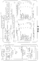
- FIG.4 illustrates one example of a power consumption output screen.
- the power consumption output screen is provided with a power consumption display section 100 and applied settings display section 200.
- the power consumption display section 100 displays current amount of power consumption of the refrigerator 1 and a reference value.
- the applied settings display section 200 displays the settings currently being applied to the refrigerator 1.
- the power consumption display section 100 displays variety of information pertaining to the refrigerator 1 based on various information such as power consumption information and operational status information obtained from the refrigerator 1.
- the power consumption display section 100 illustrated in FIG.4 is provided with: a model block 101 for displaying the name of the model of the refrigerator 1; a power consumption block 102 for displaying the power consumption of the refrigerator 1; an operational status block 103 for displaying the operational status of the refrigerator 1; and ambient temperature block 104 for displaying the ambient temperature of the refrigerator 1.
- the power consumption block 102 displays cumulative power consumption within 1 day from the present, that is, within 24 hours, meaning that cumulative power consumption of the refrigerator 1 of the past 1 day is displayed.
- the power consumption displayed in the power consumption block 102 is displayed in the unit of "kWh".
- the power consumption display section 100 is further provided with an average power consumption block 105, an average operational status block 106, and an average ambient temperature block 107.
- the average power consumption block 105 displays the average power consumption of a group of multiple refrigerators located in region A where the refrigerator 1 is located which serves as a reference value.
- the average operational status block 106 displays the average operational status of a group of multiple refrigerators located in region A where the refrigerator 1 is located.
- the average ambient temperature block 107 displays the average ambient temperature of a group of multiple refrigerators located in region A where the refrigerator 1 is located.
- the average power consumption block 105 displays average cumulative power consumption within 1 day or 24 hours from the present for a group of multiple refrigerators including refrigerator 1 in region A. That is, an average cumulative power consumption of the past 1 day in region A for a group of multiple refrigerators is displayed as a reference value.
- the power consumption displayed in the average power consumption block 105 is displayed in the unit of "kWh".
- the power consumption display section 100 is further provided with power consumption difference block 108 and a defrost operation block 109, etc.
- the power consumption difference block 108 displays the difference between power consumption of the refrigerator 1 displayed in the power consumption block 102 and the average power consumption displayed in the average power consumption block 105.
- the defrost operation block 109 displays the presence/absence of defrost operation in the refrigerator 1.
- the power consumption displayed in the power consumption difference block 108 is displayed in the unit of "kWh”. Character information which may read "defrosted” is displayed in the defrost operation block 109 when there is a history of performing the defrost operation within a prescribed period from the present, for example, in the past 1 day. Character information which may read "undefrosted” is displayed in the defrost operation block 109 when there is no history of performing the defrost operation within a prescribed period from the present.
- the applied settings display section 200 displays the settings currently applied to the refrigerator 1 based on the settings information obtained from the refrigerator 1. As illustrated in FIG.4 for example, the applied settings display section 200 is provided with a power save block 201 and refrigerator block 202, etc.
- the power save block 201 displays whether or not the refrigerator 1 is set to the power save mode. When the refrigerator 1 is set to the power save mode, character information that may read "ON" is displayed to the power save block 201. When the refrigerator 1 is not set to the power save mode, on the other hand, character information that may read "OFF" is displayed to the power save block 201.
- the refrigerator block 202 displays items such as the cooling level set to each of the storage chambers of the refrigerator 1 and whether or not any of the settings made to each of the chambers are locked.
- symbols S1, S2, and S3 are displayed where: symbol S1 indicates that the cooling level of the refrigeration chamber is set to moderate; symbol S2 indicates that the cooling level of the lower freezer chamber is set to weak; and symbol S3 indicates that settings pertaining to the refrigeration chamber are locked.
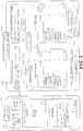
- the power consumption display section 100 is provided with a past power consumption block 110 instead of the average power consumption block 105 described above.
- the past power consumption block 110 displays power consumption of the refrigerator 1 at a prescribed period prior to the present as a reference value. For example, the power consumption of the refrigerator 1 at 1 year from the present is displayed in the unit of "kWh" to the past power consumption block 111 to provide information in the same time of year in the past year.
- the power consumption display section 100 is provided with a past operational status block 111 instead of the average operational status block 106.
- the past operational status block 111 displays the operational status of the refrigerator 1 at a prescribed period prior to the present. In this example, the operational status of the refrigerator 1 at 1 year from the present is displayed to the past operational status block 111 to provide information in the same time of year in the past year.
- the power consumption display section 100 is provided with a past ambient temperature block 112 instead of the average ambient temperature block 107.
- the past ambient temperature block 112 displays the ambient temperature of the refrigerator 1 at a prescribed period prior to the present. For example, the ambient temperature of the refrigerator 1 at 1 year from the present is displayed to the past ambient temperature block 112 to provide information in the same time of year in the past year.
- the power consumption display section 100 is further provided with a storage amount display block 113 which displays the current amount of storage of the refrigerator 1.
- the power consumption display section 100 is further provided with a past storage amount display block 114 which displays the amount of storage of at a prescribed period prior to the present. For example, the amount of storage of the refrigerator 1 at 1 year from the present is displayed to the past storage amount display block 114 to provide information in the same time of year in the past year.
- the power consumption display section 100 is further provided with an analysis block 115.
- the analysis block 115 displays insights on the cause of change in power consumption and tips on measures to be taken based on the message data produced depending upon the analysis provided by the analyzing portion.
- the power consumption display section 100 is provided with the model block 101, the power consumption block 102, and the average power consumption block 105.
- the current power consumption of the refrigerator 1 is displayed with the reference value.
- the power consumption output screen of the information output device 4 may be modified as required from the examples given above. For example, the layout of the power consumption output screen of the information output device 4 may be switched by user operation made through the operation input portion 31.
- the power consumption output device 4 of one embodiment is configured to acquire power consumption information indicating the current power consumption of the home appliance which, in this example, is refrigerator 1 when required.
- the power consumption output device 4 further displays the power consumption of the refrigerator 1 along with a reference value obtained based on the acquired power consumption information. It is thus, possible for the user to readily judge the appropriateness of the current power consumption of the refrigerator 1 through comparison with the reference value. This effectively improves the energy saving mindset of the user.
- the power consumption output device 4 is further configured to accumulate the power consumption indicated in the power consumption information acquired from the refrigerator 1 from time to time within the prescribed time period from the present and output the cumulative power consumption along with a reference value. It is thus, possible for the user to readily judge the appropriateness of the current power consumption of the refrigerator 1 through comparison with the cumulative power consumption of the refrigerator 1 within the prescribed time period prior to the present.
- the power consumption output device 4 is further configured to accumulate the power consumption indicated in the power consumption information acquired from the refrigerator 1 in the day before and output the cumulative power consumption along with a reference value. It is thus, possible for the user to readily judge the appropriateness of the current power consumption of the refrigerator 1 through comparison with the cumulative power consumption of the refrigerator 1 in the day before.
- the power consumption output device 4 is further configured to acquire power consumption information from multiple refrigerators and set the average power consumption of the group of multiple refrigerators obtained from the acquired multiple pieces of power consumption information as a reference value. It is thus, possible for the user to readily judge the appropriateness of the current power consumption of the refrigerator 1 through comparison with the average power consumption level.
- the power consumption output device 4 is further configured to acquire power consumption information from multiple refrigerators and calculate the average power consumption for each of multiple groups of refrigerators classified by model. It is thus, possible for the user to readily judge the appropriateness of the current power consumption of the refrigerator 1 through comparison with the power consumption of the group of refrigerators of the same model as the refrigerator 1 since good basis of judgement is provided through comparison with refrigerators having the same performance level.
- the power consumption output device 4 is further configured to acquire power consumption information from multiple home appliances located in the same region as the refrigerator 1. It is thus, possible for the user to readily judge the appropriateness of the current power consumption of the refrigerator 1 through comparison with the power consumption of refrigerators located in the same region where the environment is substantially the same, since good basis of judgement is provided through comparison with refrigerators being subjected to similar environment.
- the power consumption output device 4 is further configured to set the power consumption indicated in the power consumption information acquired from the refrigerator 1 at a predetermined time period of, for example, 1 year from the present as the reference value. It is thus, possible for the user to readily judge the appropriateness of the current power consumption of the refrigerator 1 through comparison with the power consumption of the refrigerator 1 in the same time of year in the year before, since good basis of judgement is provided through comparison with power consumption resulting from similar climate.
- the power consumption output device 4 is further configured to be capable of modifying the reference value based on the ambient temperature. It is thus, possible to set a more appropriate reference value.
- the power consumption output device 4 is further configured to output the operational status of the refrigerator 1 based on the operational status information acquired from the refrigerator 1 along with the power consumption and the reference value. It is thus, possible for the user to judge the appropriateness of the current power consumption of the refrigerator 1 taking the operational status into consideration.
- the operational status of the refrigerator 1 includes various operational status of the refrigerator such as the presence/absence of defrost operation of the cooler, count of door opening-closing, time of door opening-closing, temperature around the refrigerator 1, and amount of food stored in the fridge.
- the power consumption output device 4 is further configured to display the power consumption in the unit of "kWh". It is possible to make the level of power consumption to be more noticeable to the user by displaying the power consumption in a unit which is familiar to the user.
- the power consumption output device 4 is further configured to analyze the cause of change in power consumption to be displayed and display the analysis. It is thus, possible for the user to readily be aware of the cause of the change in power consumption and easily cope with such change.
- the power consumption output device 4 may be provided with a sound output device such as a speaker and output power consumption and reference value by sound instead of or with visual display.
- the information output device 4 may be configured to indicate power consumption and reference value by a rating of levels represented by number of marks such as stars and light bulbs.
- the information output device 4 may be further configured to indicate power consumption and reference value by converting them into electricity bills.
- the refrigerator 1 may be provided with a deodorizer configured to deodorize the room by applying high voltage and electrostatic atomizer configured to produce water vapor into the vegetable chamber in addition to the defroster 16 and the ice maker 17.
- the home appliance includes various types such as a washing machine and a heat cooker besides a refrigerator given above as an example.
- a home appliance with a power consumption output device of one embodiment is provided with a power consumption information acquiring unit and an output unit.
- the power consumption information acquiring unit is configured to acquire power consumption information indicating power consumption of a home appliance.
- the output unit is configured to output power consumption of the home appliance acquired based on the power consumption information acquired by the power consumption information acquiring unit along with a reference value. It is thus, possible for the user to readily judge the appropriateness of the power consumption of the home appliance through comparison with the reference value and thereby effectively improve the user's energy saving mindset.
Landscapes
- Engineering & Computer Science (AREA)
- Power Engineering (AREA)
- Physics & Mathematics (AREA)
- General Engineering & Computer Science (AREA)
- General Physics & Mathematics (AREA)
- Automation & Control Theory (AREA)
- Mechanical Engineering (AREA)
- Combustion & Propulsion (AREA)
- Chemical & Material Sciences (AREA)
- Thermal Sciences (AREA)
- Electromagnetism (AREA)
- Radar, Positioning & Navigation (AREA)
- Cold Air Circulating Systems And Constructional Details In Refrigerators (AREA)
- Devices That Are Associated With Refrigeration Equipment (AREA)
- User Interface Of Digital Computer (AREA)
- Theoretical Computer Science (AREA)
Description
- Embodiments of the present invention relate to a home appliance with a power consumption output device.
- Conventionally, technologies for displaying the amount of electric power consumption of home appliances have been conceived such as those disclosed in
patent document 1. - Furthermore,
US2013103222 (A1 ) discloses a household appliance system comprising an appliance control system having a common appliance interface provided on an appliance and a demand side management module connected to the common appliance interface. The module corresponds to one select utility of a plurality of utilities and is configured to communicate with the one select utility of the plurality of utilities. The appliance control system operates the appliance based on communications with the one select utility through the module. -
JP2002147932 (A -
US2006090482 (A1 ) discloses a freezer for a storage of blood plasma and other blood products including a user interface device which permits a user to adjust operating parameters of the freezer. The user interface device is operable to display the current status of the freezer. A defrost icon is displayed when the freezer is in defrost mode. The user interface device a graphical representation of the temperature within the freezer over the previous twenty-four hours. The controller of the freezer stores temperature related events which can be displayed on the user interface device or downloaded to a remote computer. -
US2013067375 (A1 ) discloses a refrigerator including a terminal and to a method for controlling same, and particularly, to a refrigerator including a terminal and to a method for controlling same which can visually provide necessary information to a user. To achieve this aim, this document provides a refrigerator including a terminal, comprising: a display module provided on the refrigerator; a communication unit communicating with the outside; and a control unit performing control to display various information on the display module. -
WO 02/090914 A1 - Patent Document 1:
JP 2012-133764 A - However, a refrigerator, which is one example of a home appliance, is constantly energized and thus, its electric power consumption may vary significantly depending upon usage. As such, it is difficult for the user to judge whether electric power consumption is appropriate, too high, or too low when the current electric power consumption is simply presented to the user. It is thus, not possible to improve user's energy saving mindset.
- Embodiments disclosed herein provide a home appliance with a power consumption output device capable of effectively improving the user's energy saving mindset.
- In one embodiment, a home appliance with a power consumption output device is provided with a power consumption information acquiring unit and an output unit. The power consumption information acquiring unit is configured to acquire power consumption information indicating power consumption of a home appliance. The output unit is configured to output the power consumption of the home appliance along with a reference value. The power consumption of the home appliance is obtained based on the power consumption information acquired by the power consumption information acquiring unit.
-
-
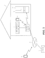
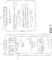
FIG.1 pertains to one embodiment and schematically illustrates a system including a power consumption output device. -
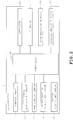
FIG.2 schematically illustrates the structure of a refrigerator which is one example of a home appliance. -
FIG.3 schematically illustrates one example of a structure of the power consumption output device. -
FIG.4 illustrates one example of an output screen of the power consumption output device (part 1). -
FIG.5 illustrates one example of an output screen of the power consumption output device (part 2). -
FIG.6 illustrates one example of an output screen of the power consumption output device (part 3) -
FIG.7 illustrates one example of an output screen of the power consumption output device (part 4). - A description will be given hereinafter on one embodiment pertaining to a home appliance with a power consumption output device with reference to the accompanying drawings.
- As illustrated in
FIG. 1 , arefrigerator 1 being one example of a home appliance, is installed in aresidence 2. Therefrigerator 1 is configured to be capable of communicating with aninformation output device 4 and amobile terminal 5. Theinformation output device 4 is one example of the power consumption output device. A wireless communication is exchanged between therefrigerator 1 and theaccess point 3 through acommunication adaptor 18 provided at the upper portion of therefrigerator 1. Through theaccess point 3, therefrigerator 1 is further capable of communicating with themobile terminal 5 and aserver 7, etc. connected to an external network 6. Theinformation output device 4 is configured by a personal computer for example and establishes wire/wireless connection with theaccess point 3. - Examples of the
mobile terminal 5 envisaged in the present embodiment include a highly functional mobile phone known as a smart phone and a tablet PC. When themobile terminal 5 is located inside aresidence 2, themobile terminal 5 is communicably connected to theaccess point 3 by a close-range wireless communication. When themobile terminal 5 is located outside theresidence 2, themobile terminal 5 is communicably connected to theaccess point 3 by a wide-range wireless communication by way of external network 6. Themobile terminal 5 is further capable of connecting to theaccess point 3 by way of the external network 6 through wide-range communication even when located inside of theresidence 2. Themobile terminal 5 located inside theresidence 2 is further capable of communicating directly with therefrigerator 1 without the intervention of theaccess point 3. In the present embodiment, a wireless LAN communication, a Bluetooth (registered trademark in Japan) wireless communication, etc. are exchanged between themobile terminal 5 and therefrigerator 1, between themobile terminal 5 and theaccess point 3, and between therefrigerator 1 and theaccess point 3. Theserver 7 is configured by a computer system known in the art. Theserver 7 stores various information for accessing therefrigerator 1 and is configured to be capable of delivering such information. Examples of information for accessing therefrigerator 1 include an IP address. - Next, a description will be given on one example of a structure of the
refrigerator 1. Therefrigerator 1 is provided with multiple storage chambers such as a refrigeration chamber, a vegetable chamber, an ice maker chamber, and a freezer chamber. As illustrated inFIG.2 for example, acontroller 10 responsible for controlling the overall operation of therefrigerator 1 based on a control program is provided inside therefrigerator 1. Thecontroller 10 is connected to acontrol panel 11, aperipheral temperature sensor 12, adoor opening sensor 13, arefrigeration cooling mechanism 14, afreeze cooler mechanism 15, adefrost mechanism 16, anice maker device 17, acommunication adaptor 18, a storageamount detection device 19, etc. - The
controller 10 is responsible for the overall control of therefrigerator 1 based on operation signals inputted from thecontrol panel 11 in response to user operation. Thecontroller 10 is further configured to detect the temperature of the periphery of therefrigerator 1 through theperipheral temperature sensor 12 which is one example of a peripheral temperature detecting unit. Thecontroller 10 is further capable of detecting the opened/closed status of the door by thedoor opening sensor 13 based on which is turned ON/OFF when the doors of the storage chambers such as the refrigeration chamber, vegetable chamber, ice maker chamber, and the freezer chamber are opened/closed. It is further possible to detect the time period in which the door is opened or closed through a timer not illustrated by counting the time period in which thedoor opening sensor 13 is turned ON or OFF. - The
refrigeration cooler mechanism 14 is provided with a refrigeration cycle known in the art including the refrigeration cooler, etc. not illustrated. Therefrigeration cooler mechanism 14 is configured to feed cool air into the storage chambers specified to the refrigeration temperature zone depending upon the drive signal inputted from thecontroller 10. Thefreeze cooling mechanism 15 is provided with a refrigeration cycle known in the art including the freeze cooler, etc. not illustrated. Thefreeze cooler mechanism 15 is configured to feed cool air into the storage chambers specified to the freeze temperature zone depending upon the drive signal inputted from thecontroller 10. - A
storage amount detector 19 is one example of a storage amount detecting unit and is configured to detect the amount of food, etc. stored in the storage chamber. In this example, thestorage amount detector 19 is provided with an optical sensor known in the art which is disposed inside the storage chamber. Thestorage amount detector 19 makes a judgement that amount of storage inside the chamber is small when illuminance inside the chamber detected by the optical sensor is high and a judgement that amount of storage inside the chamber is large when illuminance inside the chamber detected by the optical sensor is low. In this example, thestorage amount detector 19 is configured to judge the level of storage amount of food, etc. inside the fridge in the scale of ten levels ranging from 10% to 100% depending upon the illuminance inside the chamber detected by the optical sensor. - The
refrigerator 1 is capable of specifying location information for identifying the location where it is installed. For example, thecontroller 10 is configured to store and retain the location information specified when installing therefrigerator 1 into a recording medium such as a memory not illustrated. It is possible to specify such location information by, for example, inputting the address of the location, the coordinate information such as longitude and latitude of the location, or the name of the district of the location. - A
defroster 16 is provided to melt away the frost developed on the coolers of therefrigeration cooling mechanism 14 and thefreeze cooling mechanism 15. Thedefroster 16 is provided with a heater that produces heat by a supply of electricity. Power consumption increases compared to normal operation when defrost operation of thedefroster 16 is started as electricity is supplied to the heater.Ice maker 17 is configured to supply water to the ice maker carton not illustrated. Theice maker 17 is configured to detect the water temperature indirectly by detecting the temperature of the ice maker carton. The ice maker carton operates in the refrigeration cycle in the ice making mode until a judgement is made that water has frozen. When judging that water has frozen, the ice maker carton is turned to store the ice inside the ice box. When theice maker 17 starts the ice making operation, the operation of the refrigeration cycle is switched to the ice making mode and components such as a water feed motor not illustrated are driven and thus, increases power consumption compared to normal operation. - The
communication adaptor 18 is capable of communicating with theinformation output device 4, themobile terminal 5, and the like located inside theresidence 2 through theaccess point 3. Thecommunication adaptor 18 is further capable of communicating with themobile terminal 5, theserver 7, and the like located outside theresidence 2 through theaccess point 3 and the internet 6. Thecontroller 10 is capable of transmitting information such as various information pertaining to therefrigerator 1 to external devices such as theinformation output device 4 and theserver 7 through thecommunication adaptor 18. - Information being provided to the
information output device 4 from therefrigerator 1 include, for example, power consumption information indicating the power consumption of therefrigerator 1; model information identifying the model of therefrigerator 1; operational status information indicating the operational status of therefrigerator 1; setting information indicating the current settings applied to therefrigerator 1; and the location information described earlier. The operational status information include, for example, defrost history information indicating the presence/absence of defrost operation of the cooler by thedefroster 16; door opening-closing count information indicating the count of door opening-closing; peripheral temperature information indicating the peripheral temperature of therefrigerator 1; storage amount information indicating the storage amount inside the chamber detected by thestorage amount detector 19, and the like that provide various information pertaining to the operational status of therefrigerator 1. - Next, a description will be given on one example of the configuration of the
information output device 4. For example, acontroller 30 is provided inside theinformation output device 4 as illustrated inFIG.3 . Thecontroller 30 is configured to control the overall operation of theinformation output device 4 based on a control program. Thecontroller 30 is connected to anoperation input portion 31, adisplay output portion 32, and acommunication adaptor 33. Theoperation input portion 31 is configured by, for example, a touch panel switch provided on the screen of thedisplay output portion 32 and mechanical operation switches provided around thedisplay output portion 32. Thedisplay output portion 32 is configured, for example, by a liquid crystal display panel. Thecommunication adaptor 33 is capable of communicating with therefrigerator 1 andmobile terminal 5 located inside theresidence 2 through theaccess point 3. Thecommunication adaptor 33 is further capable of communicating with themobile terminal 5 and theserver 7 located outside theresidence 2 through theaccess point 3 and the internet 6. - The
controller 30 virtually implements power consumptioninformation acquiring portion 41, powerconsumption output portion 42, referencevalue setting portion 43, ambienttemperature detecting portion 44, referencevalue modifying portion 45, operational statusinformation acquiring portion 46, and analyzingportion 47 through execution of a control program by the CPU. Theseprocessing portions 41 to 47 may be implemented by hardware such as an integrated circuit. - The power consumption
information acquiring portion 41 is one example of a power consumption information acquiring unit and acquires power consumption information from therefrigerator 1 through theadaptor 33 when required. The power consumption information indicates the amount of electric power currently being consumed by therefrigerator 1. Thecontroller 30 stores the acquired power consumption information with acquisition time information identifying the time when the information was acquired. The acquisition time information is produced by time information given by a timer not illustrated provided at theinformation output device 4. The acquisition time information carries enough detail to, for example, identify the year, month, and date of acquisition. Power consumption information obtained from time to time from therefrigerator 1 is thus, stored in theinformation output device 4. Thecontroller 30 is thus, capable of identifying the power consumption of therefrigerator 1 at a first prescribed time period from the present such as 1 week, 1 month, and 1 year based on the stored power consumption information. The first prescribed time period may be modified as required. The power consumptioninformation acquiring portion 41 is capable of acquiring and storing power consumption of refrigerators not illustrated besidesrefrigerator 1. - The power
consumption output portion 42 is one example of an output unit and is configured to display, to thedisplay output portion 32, power consumption of therefrigerator 1 along with a reference value providing a standard based on the power consumption information acquired by the power consumptioninformation acquiring portion 41. - The power
consumption output portion 42 is further capable of displaying, to thedisplay output portion 32, cumulative power consumption along with a reference value. The cumulative power consumption is an accumulation of power consumption indicated in the power consumption information obtained by the power consumptioninformation acquiring portion 41 from time to time in a second prescribed time period from the present. That is, the powerconsumption output portion 42 is capable of displaying a cumulative amount of electric power consumed by therefrigerator 1 in a second prescribed time period from the present. The second prescribed time period, being variable, is basically shorter than the first prescribed time period. For example, settings may be made so that the powerconsumption output portion 42 is capable of displaying cumulative power consumption of therefrigerator 1 in the past day, that is, within 24 hours. - The power
consumption output portion 42 is further capable of displaying, to thedisplay output portion 32, cumulative power consumption of the day before along with a reference value. Again, the cumulative power consumption is an accumulation of power consumption indicated in the power consumption information obtained by the power consumptioninformation acquiring portion 41 from time to time. That is, the powerconsumption output portion 42 is capable of displaying a cumulative amount of electric power consumed by therefrigerator 1 in the day before. For example, settings may be made so that the powerconsumption output portion 42 is capable of displaying the cumulative power consumption of therefrigerator 1 within 1 day, i.e. 24 hours or less from the present. The powerconsumption output portion 42 is capable of displaying the cumulative power consumption of therefrigerator 1 in the range of 0:00 to 24:00 in 1 calendar day before the present day. - A reference
value setting portion 43 is one example of a reference value setting unit and is configured to set a reference amount of electric power consumed by therefrigerator 1 on thedisplay output portion 32 along with the actual cumulative amount of electric power consumed. The reference value may be set in various ways. - When power consumption information for
multiple refrigerators 1 including therefrigerator 1 has been acquired by the power consumptioninformation acquiring portion 41, the referencevalue setting portion 43 is capable of calculating an average power consumption of the multiple refrigerators based on the multiple pieces of power consumption information and setting the average value as the reference value. When model information is appended to the acquired power consumption information, the referencevalue setting portion 43 is capable of identifying the model of each refrigerator based on the model information and providing an average value for the refrigerators of the same type. The referencevalue setting portion 43 may be configured to calculate an average value of only a group of refrigerators of the same model as therefrigerator 1. - When location information is appended to the acquired power consumption information, the reference
value setting portion 43 is capable of identifying the refrigerators located in the prescribed region based on the location information and providing an average value for the refrigerators located in the prescribed region. The referencevalue setting portion 43 may be configured to calculate an average value of only a group of refrigerators located in the same region as therefrigerator 1. - The reference
value setting portion 43 is further capable of setting the power consumption indicated in the power consumption information which was acquired by the power consumptioninformation acquiring portion 41 at a timing preceding the present by the first prescribed period. - The ambient
temperature detecting portion 44 is one example of an ambient temperature detecting unit and is configured to detect ambient temperature by a temperature sensor not illustrated provided to theinformation output device 4. The ambienttemperature detecting portion 44 is configured to output ambient temperature information indicating the detected temperature to thecontroller 30. The "ambient temperature" denotes the temperature outside theinformation output device 4 and may indicate the temperature inside or outside theresidence 2 as long as the temperature pertains to the outside of theinformation output device 4. It is possible to detect temperatures of various locations outside theinformation output device 4 by changing the location where the temperature sensor not illustrated is installed inside or outside theresidence 2. - A reference
value modifying portion 45 is configured to modify the reference value set by the referencevalue setting portion 43 based on the ambient temperature detected by the ambienttemperature detecting portion 44. The referencevalue modifying portion 45 increases the reference value by a prescribed amount when the ambient temperature is higher than a prescribed value. The referencevalue modifying portion 45 reduces the reference value by a prescribed amount when the ambient temperature is lower than a prescribed value. The prescribed value and the prescribed amount used in the modification are variable. - An operational state
information acquiring portion 46 is one example of an operational state information acquiring unit and is configured to acquire operational status information indicating the operational status of therefrigerator 1 through thecommunication adaptor 33. The powerconsumption output portion 42 is capable of displaying the operational status indicated in the operational status information to thedisplay output portion 32 along with power consumption and reference value when the operational status information has been obtained by the operational stateinformation acquiring portion 46. The operational statusinformation acquiring portion 46 is capable of acquiring operational status information indicating the operational status of the refrigerator from refrigerators other than therefrigerator 1. - An analyzing
portion 47 is one example of an analyzingunit 47 and is configured to analyze the cause of change encountered in the power consumption outputted by the powerconsumption output portion 42. The analyzingportion 47 is configured to analyze the cause of change in the power consumption outputted by the powerconsumption output portion 42 when abnormal change is observed in the power consumption such as a significant increase in a short period of time and significant increase compared to similar time of year in the year before. For example, when the present power consumption is greater than the power consumption in the similar time of year of the year before by a prescribed amount of 0.2kWh or more, the analyzingportion 47 verifies the operational state of therefrigerator 1 based on the operational status information obtained from therefrigerator 1. The analyzingportion 47 is configured to produce message data reading, for example, "The fridge interior is not cooled well because of excessive storage. Try organizing the stored items in the fridge. Stay alert on the count of door opening-closing". - The
information output device 4 is capable of outputting power consumption of therefrigerator 1, being one example of a home appliance, along with a reference value. Different modes for outputting power consumption will be described through examples given herein. -
FIG.4 illustrates one example of a power consumption output screen. The power consumption output screen is provided with a powerconsumption display section 100 and appliedsettings display section 200. The powerconsumption display section 100 displays current amount of power consumption of therefrigerator 1 and a reference value. The appliedsettings display section 200 displays the settings currently being applied to therefrigerator 1. - The power
consumption display section 100 displays variety of information pertaining to therefrigerator 1 based on various information such as power consumption information and operational status information obtained from therefrigerator 1. For example, the powerconsumption display section 100 illustrated inFIG.4 is provided with: amodel block 101 for displaying the name of the model of therefrigerator 1; apower consumption block 102 for displaying the power consumption of therefrigerator 1; anoperational status block 103 for displaying the operational status of therefrigerator 1; andambient temperature block 104 for displaying the ambient temperature of therefrigerator 1. Thepower consumption block 102 displays cumulative power consumption within 1 day from the present, that is, within 24 hours, meaning that cumulative power consumption of therefrigerator 1 of the past 1 day is displayed. The power consumption displayed in thepower consumption block 102 is displayed in the unit of "kWh". - The power
consumption display section 100 is further provided with an averagepower consumption block 105, an averageoperational status block 106, and an averageambient temperature block 107. The averagepower consumption block 105 displays the average power consumption of a group of multiple refrigerators located in region A where therefrigerator 1 is located which serves as a reference value. The averageoperational status block 106 displays the average operational status of a group of multiple refrigerators located in region A where therefrigerator 1 is located. The averageambient temperature block 107 displays the average ambient temperature of a group of multiple refrigerators located in region A where therefrigerator 1 is located. The averagepower consumption block 105 displays average cumulative power consumption within 1 day or 24 hours from the present for a group of multiplerefrigerators including refrigerator 1 in region A. That is, an average cumulative power consumption of the past 1 day in region A for a group of multiple refrigerators is displayed as a reference value. The power consumption displayed in the averagepower consumption block 105 is displayed in the unit of "kWh". - The power
consumption display section 100 is further provided with powerconsumption difference block 108 and adefrost operation block 109, etc. The power consumption difference block 108 displays the difference between power consumption of therefrigerator 1 displayed in thepower consumption block 102 and the average power consumption displayed in the averagepower consumption block 105. The defrost operation block 109 displays the presence/absence of defrost operation in therefrigerator 1. The power consumption displayed in the powerconsumption difference block 108 is displayed in the unit of "kWh". Character information which may read "defrosted" is displayed in the defrost operation block 109 when there is a history of performing the defrost operation within a prescribed period from the present, for example, in the past 1 day. Character information which may read "undefrosted" is displayed in the defrost operation block 109 when there is no history of performing the defrost operation within a prescribed period from the present. - The applied
settings display section 200 displays the settings currently applied to therefrigerator 1 based on the settings information obtained from therefrigerator 1. As illustrated inFIG.4 for example, the appliedsettings display section 200 is provided with a power saveblock 201 andrefrigerator block 202, etc. The power saveblock 201 displays whether or not therefrigerator 1 is set to the power save mode. When therefrigerator 1 is set to the power save mode, character information that may read "ON" is displayed to the power saveblock 201. When therefrigerator 1 is not set to the power save mode, on the other hand, character information that may read "OFF" is displayed to the power saveblock 201. - The
refrigerator block 202 displays items such as the cooling level set to each of the storage chambers of therefrigerator 1 and whether or not any of the settings made to each of the chambers are locked. In the example illustrated inFIG.4 , symbols S1, S2, and S3 are displayed where: symbol S1 indicates that the cooling level of the refrigeration chamber is set to moderate; symbol S2 indicates that the cooling level of the lower freezer chamber is set to weak; and symbol S3 indicates that settings pertaining to the refrigeration chamber are locked. - In the example illustrated in
FIG.5 , the powerconsumption display section 100 is provided with a pastpower consumption block 110 instead of the averagepower consumption block 105 described above. The pastpower consumption block 110 displays power consumption of therefrigerator 1 at a prescribed period prior to the present as a reference value. For example, the power consumption of therefrigerator 1 at 1 year from the present is displayed in the unit of "kWh" to the pastpower consumption block 111 to provide information in the same time of year in the past year. - The power
consumption display section 100 is provided with a pastoperational status block 111 instead of the averageoperational status block 106. The pastoperational status block 111 displays the operational status of therefrigerator 1 at a prescribed period prior to the present. In this example, the operational status of therefrigerator 1 at 1 year from the present is displayed to the pastoperational status block 111 to provide information in the same time of year in the past year. - The power
consumption display section 100 is provided with a pastambient temperature block 112 instead of the averageambient temperature block 107. The pastambient temperature block 112 displays the ambient temperature of therefrigerator 1 at a prescribed period prior to the present. For example, the ambient temperature of therefrigerator 1 at 1 year from the present is displayed to the pastambient temperature block 112 to provide information in the same time of year in the past year. - The power
consumption display section 100 is further provided with a storageamount display block 113 which displays the current amount of storage of therefrigerator 1. The powerconsumption display section 100 is further provided with a past storageamount display block 114 which displays the amount of storage of at a prescribed period prior to the present. For example, the amount of storage of therefrigerator 1 at 1 year from the present is displayed to the past storageamount display block 114 to provide information in the same time of year in the past year. - In the example illustrated in
FIG.6 , the powerconsumption display section 100 is further provided with ananalysis block 115. Theanalysis block 115 displays insights on the cause of change in power consumption and tips on measures to be taken based on the message data produced depending upon the analysis provided by the analyzing portion. - In the example illustrated in
FIG.7 , the powerconsumption display section 100 is provided with themodel block 101, thepower consumption block 102, and the averagepower consumption block 105. In the example illustrated inFIG.7 , the current power consumption of therefrigerator 1 is displayed with the reference value. The power consumption output screen of theinformation output device 4 may be modified as required from the examples given above. For example, the layout of the power consumption output screen of theinformation output device 4 may be switched by user operation made through theoperation input portion 31. - The power
consumption output device 4 of one embodiment is configured to acquire power consumption information indicating the current power consumption of the home appliance which, in this example, isrefrigerator 1 when required. The powerconsumption output device 4 further displays the power consumption of therefrigerator 1 along with a reference value obtained based on the acquired power consumption information. It is thus, possible for the user to readily judge the appropriateness of the current power consumption of therefrigerator 1 through comparison with the reference value. This effectively improves the energy saving mindset of the user. - The power
consumption output device 4 is further configured to accumulate the power consumption indicated in the power consumption information acquired from therefrigerator 1 from time to time within the prescribed time period from the present and output the cumulative power consumption along with a reference value. It is thus, possible for the user to readily judge the appropriateness of the current power consumption of therefrigerator 1 through comparison with the cumulative power consumption of therefrigerator 1 within the prescribed time period prior to the present. - The power
consumption output device 4 is further configured to accumulate the power consumption indicated in the power consumption information acquired from therefrigerator 1 in the day before and output the cumulative power consumption along with a reference value. It is thus, possible for the user to readily judge the appropriateness of the current power consumption of therefrigerator 1 through comparison with the cumulative power consumption of therefrigerator 1 in the day before. - The power
consumption output device 4 is further configured to acquire power consumption information from multiple refrigerators and set the average power consumption of the group of multiple refrigerators obtained from the acquired multiple pieces of power consumption information as a reference value. It is thus, possible for the user to readily judge the appropriateness of the current power consumption of therefrigerator 1 through comparison with the average power consumption level. - The power
consumption output device 4 is further configured to acquire power consumption information from multiple refrigerators and calculate the average power consumption for each of multiple groups of refrigerators classified by model. It is thus, possible for the user to readily judge the appropriateness of the current power consumption of therefrigerator 1 through comparison with the power consumption of the group of refrigerators of the same model as therefrigerator 1 since good basis of judgement is provided through comparison with refrigerators having the same performance level. - The power
consumption output device 4 is further configured to acquire power consumption information from multiple home appliances located in the same region as therefrigerator 1. It is thus, possible for the user to readily judge the appropriateness of the current power consumption of therefrigerator 1 through comparison with the power consumption of refrigerators located in the same region where the environment is substantially the same, since good basis of judgement is provided through comparison with refrigerators being subjected to similar environment. - The power
consumption output device 4 is further configured to set the power consumption indicated in the power consumption information acquired from therefrigerator 1 at a predetermined time period of, for example, 1 year from the present as the reference value. It is thus, possible for the user to readily judge the appropriateness of the current power consumption of therefrigerator 1 through comparison with the power consumption of therefrigerator 1 in the same time of year in the year before, since good basis of judgement is provided through comparison with power consumption resulting from similar climate. - The power
consumption output device 4 is further configured to be capable of modifying the reference value based on the ambient temperature. It is thus, possible to set a more appropriate reference value. - The power
consumption output device 4 is further configured to output the operational status of therefrigerator 1 based on the operational status information acquired from therefrigerator 1 along with the power consumption and the reference value. It is thus, possible for the user to judge the appropriateness of the current power consumption of therefrigerator 1 taking the operational status into consideration. The operational status of therefrigerator 1 includes various operational status of the refrigerator such as the presence/absence of defrost operation of the cooler, count of door opening-closing, time of door opening-closing, temperature around therefrigerator 1, and amount of food stored in the fridge. - The power
consumption output device 4 is further configured to display the power consumption in the unit of "kWh". It is possible to make the level of power consumption to be more noticeable to the user by displaying the power consumption in a unit which is familiar to the user. - The power
consumption output device 4 is further configured to analyze the cause of change in power consumption to be displayed and display the analysis. It is thus, possible for the user to readily be aware of the cause of the change in power consumption and easily cope with such change. - The embodiments described above may be modified or expanded as described below.
- The power
consumption output device 4 may be provided with a sound output device such as a speaker and output power consumption and reference value by sound instead of or with visual display. - The
information output device 4 may be configured to indicate power consumption and reference value by a rating of levels represented by number of marks such as stars and light bulbs. Theinformation output device 4 may be further configured to indicate power consumption and reference value by converting them into electricity bills. - The
refrigerator 1 may be provided with a deodorizer configured to deodorize the room by applying high voltage and electrostatic atomizer configured to produce water vapor into the vegetable chamber in addition to thedefroster 16 and theice maker 17. The home appliance includes various types such as a washing machine and a heat cooker besides a refrigerator given above as an example. - A home appliance with a power consumption output device of one embodiment is provided with a power consumption information acquiring unit and an output unit. The power consumption information acquiring unit is configured to acquire power consumption information indicating power consumption of a home appliance. The output unit is configured to output power consumption of the home appliance acquired based on the power consumption information acquired by the power consumption information acquiring unit along with a reference value. It is thus, possible for the user to readily judge the appropriateness of the power consumption of the home appliance through comparison with the reference value and thereby effectively improve the user's energy saving mindset.
Claims (13)
- Home appliance with a power consumption output device (4) said power consumption output device (4) comprising:a power consumption information acquiring unit (41) configured to acquire power consumption information indicating power consumption of a home appliance (1);an output unit (32) configured to output the power consumption of the home appliance (1) along with a reference value providing a standard based on the power consumption information for judging whether power consumption is appropriate, the power consumption of the home appliance (1) being obtained based on the power consumption information acquired by the power consumption information acquiring unit (41),a reference value setting unit (43) configured to set the reference value, wherein the output unit (32) is configured to accumulate power consumption indicated in the power consumption information acquiring unit (41) within a prescribed period prior to the present and output a cumulative power consumption along with the reference value, characterised in that the power consumption output device(4) further comprisesan ambient temperature detecting unit (44) configured to detect ambient temperature pertaining to the outside of the power consumption output device (4),a reference value modifying unit (45) configured to modify the reference value set by the reference value setting unit (43), wherein the reference value modifying unit (45) is configured to modify the reference value set by the reference value setting unit (43) based on the ambient temperature detected by the ambient temperature detecting unit (44), whereby the reference value modifying unit (45) increases the reference value by a prescribed amount when the ambient temperature is higher than a prescribed value, and reduces the reference value by a prescribed amount when the ambient temperature is lower than a prescribed value.
- Home appliance according to claim 1, wherein the output unit (32) is configured to accumulate power consumption indicated in the power consumption information acquired by the power consumption information acquiring unit (41) one day before the present and output a cumulative power consumption along with the reference value.
- Home appliance according to any one of claims 1 or 2, wherein the power consumption information acquiring unit (41) is configured to acquire multiple pieces of the power consumption information from multiple home appliances (1), and wherein the reference value setting unit (43) is configured to set an average power consumption of the home appliances (1) as the reference value based on the multiple pieces of the power consumption information acquired by the power consumption information acquiring unit (41).
- Home appliance according to claim 3, wherein the reference value setting unit (43) is configured to calculate the average power consumption for the home appliances (1) of the same model.
- Home appliance according to claim 3, wherein the reference value setting unit (43) is configured to calculate the average power consumption for the home appliances (1) located in a prescribed region.
- Home appliance according to any one of claims 1 to 2, wherein the reference value setting unit (43) is configured to set power consumption indicated in the power consumption information acquired a prescribed time period before the present by the power consumption information acquiring unit (41) as the reference value.
- Home appliance according to any one of claims 1 to 6, with the power consumption output device (4) further comprising an operational status information acquiring unit (46) configured to acquire operational status information indicating an operational status of the home appliance (1),
wherein the output unit (32) is configured to display the operational status of the home appliance (1) along with the power consumption and the reference value based on the operational status information acquired by the operational status information acquiring unit (46). - Home appliance according to claim 7, wherein the home appliance is a refrigerator (1) provided with a cooler and the operational status information acquiring unit (46) is configured to acquire, as the operational status information, defrost history information indicating presence and absence of execution of a defrost operation in the cooler of the refrigerator (1).
- Home appliance according to claim 7, wherein the home appliance is a refrigerator (1) provided with a door and the operational status information acquiring unit (46) is configured to acquire, as the operational status information, door opening closing count information indicating a count of times in which the door was opened and closed.
- Home appliance according to claim 7, wherein the home appliance is a refrigerator (1) provided with a door and the operational status information acquiring unit (46) is configured to acquire, as the operational status information, door opening closing time information indicating a time expended on opening and closing the door.
- Home appliance according to claim 7, wherein the home appliance is a refrigerator provided with a peripheral temperature detecting unit (12) configured to detect temperature around the refrigerator (1), and the operational status information acquiring unit (46) is configured to acquire, as the operational status information, peripheral temperature information indicating the temperature around the refrigerator detected by the peripheral temperature detecting unit (12).
- Home appliance according to claim 7, wherein the home appliance is a refrigerator (1) provided with a storage amount detecting unit configured to detect amount of food stored in the refrigerator, and the operational status information acquiring unit (46) is configured to acquire, as the operational status information, storage amount information indicating the amount of food stored in the refrigerator detected by the storage amount detecting unit.
- Home appliance according to any one of claims 1 to 12, wherein the power consumption displayed by the output unit (32) is displayed in a unit of kWh.
Applications Claiming Priority (2)
| Application Number | Priority Date | Filing Date | Title |
|---|---|---|---|
| JP2013174493A JP6430106B2 (en) | 2013-08-26 | 2013-08-26 | Power consumption output device |
| PCT/JP2014/068052 WO2015029600A1 (en) | 2013-08-26 | 2014-07-07 | Power-consumption output device |
Publications (3)
| Publication Number | Publication Date |
|---|---|
| EP3040658A1 EP3040658A1 (en) | 2016-07-06 |
| EP3040658A4 EP3040658A4 (en) | 2017-05-31 |
| EP3040658B1 true EP3040658B1 (en) | 2020-08-19 |
Family
ID=52586177
Family Applications (1)
| Application Number | Title | Priority Date | Filing Date |
|---|---|---|---|
| EP14839818.3A Active EP3040658B1 (en) | 2013-08-26 | 2014-07-07 | Home appliance with a power-consumption output device |
Country Status (7)
| Country | Link |
|---|---|
| US (1) | US10126047B2 (en) |
| EP (1) | EP3040658B1 (en) |
| JP (1) | JP6430106B2 (en) |
| KR (1) | KR20160035016A (en) |
| CN (1) | CN105492844B (en) |
| TW (1) | TWI639081B (en) |
| WO (1) | WO2015029600A1 (en) |
Cited By (1)
| Publication number | Priority date | Publication date | Assignee | Title |
|---|---|---|---|---|
| EP4047293A3 (en) * | 2021-02-02 | 2022-12-21 | True Manufacturing Co., Inc. | Systems, methods, and appliances that enable regional control of refrigeration appliances |
Families Citing this family (7)
| Publication number | Priority date | Publication date | Assignee | Title |
|---|---|---|---|---|
| WO2014145153A2 (en) | 2013-03-15 | 2014-09-18 | Neeley John | Automatic recording and graphing of measurement data |
| JP6080655B2 (en) * | 2013-04-03 | 2017-02-15 | 三菱電機株式会社 | refrigerator |
| SG10201805510YA (en) | 2018-06-26 | 2020-01-30 | Luxon Data Holdings Pte Ltd | Monitoring device and system |
| JP2020046093A (en) * | 2018-09-18 | 2020-03-26 | パナソニックIpマネジメント株式会社 | Refrigerator and system |
| WO2022102633A1 (en) * | 2020-11-16 | 2022-05-19 | シャープ株式会社 | Status reporting device, program, and status reporting method |
| JP7387694B2 (en) * | 2021-11-16 | 2023-11-28 | 東芝ライフスタイル株式会社 | Program and refrigerator |
| CN114739090B (en) * | 2022-04-13 | 2024-06-18 | 海信冰箱有限公司 | Refrigerator and power consumption monitoring method thereof |
Citations (1)
| Publication number | Priority date | Publication date | Assignee | Title |
|---|---|---|---|---|
| WO2002090914A1 (en) * | 2001-05-03 | 2002-11-14 | Emerson Retail Services Inc. | Model-based alarming |
Family Cites Families (36)
| Publication number | Priority date | Publication date | Assignee | Title |
|---|---|---|---|---|
| JPH10123185A (en) * | 1996-10-22 | 1998-05-15 | Kajima Corp | Power-consumption-amount monitor |
| JP4329131B2 (en) * | 1998-05-21 | 2009-09-09 | パナソニック株式会社 | Refrigerator usage comparison system and control method thereof |
| JP4682414B2 (en) * | 2000-11-06 | 2011-05-11 | パナソニック株式会社 | Storage |
| JP4346584B2 (en) * | 2004-08-12 | 2009-10-21 | 三洋電機株式会社 | Demand control apparatus and program |
| US7617690B2 (en) * | 2004-11-02 | 2009-11-17 | Helmer, Inc. | Blood products freezer with event log |
| US20060123807A1 (en) * | 2004-12-14 | 2006-06-15 | Sullivan C B | Apparatus and method for monitoring and displaying power usage |
| JP2006190145A (en) * | 2005-01-07 | 2006-07-20 | Omron Corp | Store management system, store controller, store control method, management server, management method and program |
| CN100594648C (en) * | 2005-06-01 | 2010-03-17 | 三洋电机株式会社 | Demand control apparatus and power consumption prediction method |
| JP2007060848A (en) * | 2005-08-26 | 2007-03-08 | Sanyo Electric Co Ltd | Apparatus and method for controlling electric energy and its program |
| US7409258B2 (en) * | 2006-04-28 | 2008-08-05 | Taiwan Semiconductor Manufacturing Company, Ltd. | Method and system for measuring customer delivery service |
| JP4775338B2 (en) * | 2007-07-12 | 2011-09-21 | ダイキン工業株式会社 | Air conditioner deterioration determination device, air conditioning system, deterioration determination method, and deterioration determination program |
| US7693670B2 (en) | 2007-08-14 | 2010-04-06 | General Electric Company | Cognitive electric power meter |
| JP4966921B2 (en) * | 2008-07-03 | 2012-07-04 | 株式会社日立製作所 | Deterioration diagnosis apparatus, deterioration diagnosis method, and deterioration diagnosis system for cooling / heating supply system |
| WO2010031013A1 (en) | 2008-09-15 | 2010-03-18 | General Electric Company | Energy management of household appliances |
| TWI419431B (en) | 2008-11-06 | 2013-12-11 | 財團法人工業技術研究院 | Socket with power management ability |
| TWI513947B (en) | 2008-12-24 | 2015-12-21 | Panasonic Corp | Refrigerators and compressors |
| TWM360365U (en) | 2009-01-23 | 2009-07-01 | Josephtec Co Ltd | Electric power meter and its corresponding display device with varieties of input and output wire sleeve configuration |
| CN103697652B (en) * | 2009-03-27 | 2016-01-20 | 三菱电机株式会社 | Electrostatic atomization apparatus, equipment, air regulator and refrigerator |
| US8706266B2 (en) | 2009-09-09 | 2014-04-22 | Panasonic Corporation | Power control system |
| KR101595391B1 (en) * | 2009-10-26 | 2016-02-18 | 엘지전자 주식회사 | Apparatus for controlling washing machine and method the same |
| JP5853163B2 (en) | 2010-01-14 | 2016-02-09 | パナソニックIpマネジメント株式会社 | refrigerator |
| KR101637354B1 (en) * | 2010-01-20 | 2016-07-07 | 엘지전자 주식회사 | A refrigerator and a control method thereof |
| US9353990B2 (en) * | 2010-02-23 | 2016-05-31 | Lg Electronics Inc. | Refrigerator including a terminal, and method for controlling same |
| DE102010030830A1 (en) * | 2010-07-01 | 2012-01-05 | Robert Bosch Gmbh | Method for operating a temperature limiting device, temperature limiting device and electrical device |
| TWI423549B (en) * | 2010-07-02 | 2014-01-11 | Univ Nat Chiao Tung | Power monitoring device for identifying state of electric equipment and power monitoring method thereof |
| JP2012133764A (en) | 2010-12-02 | 2012-07-12 | Sharp Corp | Controller, network system, and information processing method |
| EP2469328A1 (en) | 2010-12-22 | 2012-06-27 | Chimei InnoLux Corporation | Method for fabricating a touch panel |
| CN103270663B (en) * | 2010-12-24 | 2015-10-21 | Lg电子株式会社 | Management of power use device and management of power use method |
| US9111440B2 (en) * | 2011-01-06 | 2015-08-18 | Lg Electronics Inc. | Refrigerator and remote controller |
| USD672666S1 (en) | 2011-01-12 | 2012-12-18 | Emerson Electric Co. | Thermostat |
| US20120176252A1 (en) * | 2011-01-12 | 2012-07-12 | Emerson Electric Co. | Apparatus and Method for Determining Load of Energy Consuming Appliances Within a Premises |
| TWM408027U (en) | 2011-01-18 | 2011-07-21 | Univ Far East | intelligent refrigerator |
| JP5085751B2 (en) * | 2011-02-28 | 2012-11-28 | 株式会社東芝 | Electronic device and information output method |
| TW201322579A (en) | 2011-11-25 | 2013-06-01 | Chunghwa Telecom Co Ltd | Cloud energy monitoring system and method |
| EP2793344A4 (en) * | 2011-12-14 | 2015-07-01 | Kyocera Corp | Display terminal, power control system, and display method |
| JP4962813B1 (en) | 2012-01-23 | 2012-06-27 | 日本テクノ株式会社 | Alarm output device and alarm output method |
-
2013
- 2013-08-26 JP JP2013174493A patent/JP6430106B2/en not_active Expired - Fee Related
-
2014
- 2014-07-07 KR KR1020167004650A patent/KR20160035016A/en active Search and Examination
- 2014-07-07 EP EP14839818.3A patent/EP3040658B1/en active Active
- 2014-07-07 CN CN201480047757.4A patent/CN105492844B/en not_active Expired - Fee Related
- 2014-07-07 WO PCT/JP2014/068052 patent/WO2015029600A1/en active Application Filing
- 2014-07-18 TW TW103124652A patent/TWI639081B/en not_active IP Right Cessation
-
2016
- 2016-02-25 US US15/053,520 patent/US10126047B2/en not_active Expired - Fee Related
Patent Citations (1)
| Publication number | Priority date | Publication date | Assignee | Title |
|---|---|---|---|---|
| WO2002090914A1 (en) * | 2001-05-03 | 2002-11-14 | Emerson Retail Services Inc. | Model-based alarming |
Cited By (2)
| Publication number | Priority date | Publication date | Assignee | Title |
|---|---|---|---|---|
| EP4047293A3 (en) * | 2021-02-02 | 2022-12-21 | True Manufacturing Co., Inc. | Systems, methods, and appliances that enable regional control of refrigeration appliances |
| US11936489B2 (en) | 2021-02-02 | 2024-03-19 | True Manufacturing Co., Inc. | Systems, methods, and appliances that enable regional control of refrigeration appliances |
Also Published As
| Publication number | Publication date |
|---|---|
| JP2015042927A (en) | 2015-03-05 |
| KR20160035016A (en) | 2016-03-30 |
| JP6430106B2 (en) | 2018-11-28 |
| TWI639081B (en) | 2018-10-21 |
| US20160169577A1 (en) | 2016-06-16 |
| EP3040658A1 (en) | 2016-07-06 |
| CN105492844B (en) | 2019-05-03 |
| TW201516641A (en) | 2015-05-01 |
| US10126047B2 (en) | 2018-11-13 |
| CN105492844A (en) | 2016-04-13 |
| EP3040658A4 (en) | 2017-05-31 |
| WO2015029600A1 (en) | 2015-03-05 |
Similar Documents
| Publication | Publication Date | Title |
|---|---|---|
| EP3040658B1 (en) | Home appliance with a power-consumption output device | |
| US8461861B2 (en) | Energy usage monitor for a household appliance | |
| EP2662651B1 (en) | Refrigerator comprising a display | |
| KR101779728B1 (en) | Home electrical appliance and network system | |
| US20190137169A1 (en) | Information terminal device, operating information provision system, and operating information provision program | |
| CN105102911A (en) | Refrigerator | |
| US20130098083A1 (en) | Refrigerator | |
| CN102878776A (en) | Refrigerator and control method thereof | |
| KR20170139374A (en) | Refrigerator with temperature context awareness and method of controlling thereof | |
| JP6905869B2 (en) | Home appliance systems, home appliance diagnostic methods, and terminal devices | |
| KR20140099594A (en) | Method for controlling refrigerator | |
| CN113280551A (en) | Commercial refrigerator | |
| CN107894129A (en) | A kind of commercial refrigerator intelligence control system | |
| DK178891B1 (en) | Control system for refrigerated equipment and apparatus with advanced energy saving features | |
| JP2023073773A (en) | program and refrigerator | |
| KR101943314B1 (en) | Refrigerator and Controlling Method for the same | |
| CN115638600A (en) | Cold insulation time prediction system | |
| JP5589882B2 (en) | Refrigerator, defrost control device and defrost control method | |
| CN117663661A (en) | Method and device for controlling air-cooled refrigerator, air-cooled refrigerator and computer readable storage medium | |
| CN115585602A (en) | Cold insulation time prediction system | |
| JP2012097970A (en) | Refrigerator, defrosting control device, and defrosting control method | |
| KR20120080083A (en) | Refrigerator | |
| KR20080050164A (en) | Refrigerator having usb memory |
Legal Events
| Date | Code | Title | Description |
|---|---|---|---|
| PUAI | Public reference made under article 153(3) epc to a published international application that has entered the european phase |
Free format text: ORIGINAL CODE: 0009012 |
|
| 17P | Request for examination filed |
Effective date: 20160318 |
|
| AK | Designated contracting states |
Kind code of ref document: A1 Designated state(s): AL AT BE BG CH CY CZ DE DK EE ES FI FR GB GR HR HU IE IS IT LI LT LU LV MC MK MT NL NO PL PT RO RS SE SI SK SM TR |
|
| AX | Request for extension of the european patent |
Extension state: BA ME |
|
| DAX | Request for extension of the european patent (deleted) | ||
| RAP1 | Party data changed (applicant data changed or rights of an application transferred) |
Owner name: TOSHIBA LIFESTYLE PRODUCTS & SERVICES CORPORATION |
|
| A4 | Supplementary search report drawn up and despatched |
Effective date: 20170428 |
|
| RIC1 | Information provided on ipc code assigned before grant |
Ipc: G06F 13/00 20060101ALI20170421BHEP Ipc: H02J 13/00 20060101ALI20170421BHEP Ipc: F25D 29/00 20060101AFI20170421BHEP Ipc: G06F 3/048 20130101ALI20170421BHEP |
|
| STAA | Information on the status of an ep patent application or granted ep patent |
Free format text: STATUS: EXAMINATION IS IN PROGRESS |
|
| 17Q | First examination report despatched |
Effective date: 20190708 |
|
| REG | Reference to a national code |
Ref country code: DE Ref legal event code: R079 Ref document number: 602014069253 Country of ref document: DE Free format text: PREVIOUS MAIN CLASS: F25D0011000000 Ipc: F25D0029000000 |
|
| RIC1 | Information provided on ipc code assigned before grant |
Ipc: F25D 29/00 20060101AFI20191217BHEP Ipc: G01D 4/02 20060101ALN20191217BHEP Ipc: H02J 13/00 20060101ALI20191217BHEP Ipc: G05F 1/66 20060101ALI20191217BHEP |
|
| GRAP | Despatch of communication of intention to grant a patent |
Free format text: ORIGINAL CODE: EPIDOSNIGR1 |
|
| STAA | Information on the status of an ep patent application or granted ep patent |
Free format text: STATUS: GRANT OF PATENT IS INTENDED |
|
| INTG | Intention to grant announced |
Effective date: 20200131 |
|
| GRAS | Grant fee paid |
Free format text: ORIGINAL CODE: EPIDOSNIGR3 |
|
| GRAA | (expected) grant |
Free format text: ORIGINAL CODE: 0009210 |
|
| STAA | Information on the status of an ep patent application or granted ep patent |
Free format text: STATUS: THE PATENT HAS BEEN GRANTED |
|
| AK | Designated contracting states |
Kind code of ref document: B1 Designated state(s): AL AT BE BG CH CY CZ DE DK EE ES FI FR GB GR HR HU IE IS IT LI LT LU LV MC MK MT NL NO PL PT RO RS SE SI SK SM TR |
|
| REG | Reference to a national code |
Ref country code: CH Ref legal event code: EP |
|
| REG | Reference to a national code |
Ref country code: DE Ref legal event code: R096 Ref document number: 602014069253 Country of ref document: DE |
|
| REG | Reference to a national code |
Ref country code: AT Ref legal event code: REF Ref document number: 1304403 Country of ref document: AT Kind code of ref document: T Effective date: 20200915 |
|
| REG | Reference to a national code |
Ref country code: IE Ref legal event code: FG4D |
|
| REG | Reference to a national code |
Ref country code: LT Ref legal event code: MG4D |
|
| REG | Reference to a national code |
Ref country code: NL Ref legal event code: MP Effective date: 20200819 |
|
| PG25 | Lapsed in a contracting state [announced via postgrant information from national office to epo] |
Ref country code: BG Free format text: LAPSE BECAUSE OF FAILURE TO SUBMIT A TRANSLATION OF THE DESCRIPTION OR TO PAY THE FEE WITHIN THE PRESCRIBED TIME-LIMIT Effective date: 20201119 Ref country code: GR Free format text: LAPSE BECAUSE OF FAILURE TO SUBMIT A TRANSLATION OF THE DESCRIPTION OR TO PAY THE FEE WITHIN THE PRESCRIBED TIME-LIMIT Effective date: 20201120 Ref country code: PT Free format text: LAPSE BECAUSE OF FAILURE TO SUBMIT A TRANSLATION OF THE DESCRIPTION OR TO PAY THE FEE WITHIN THE PRESCRIBED TIME-LIMIT Effective date: 20201221 Ref country code: LT Free format text: LAPSE BECAUSE OF FAILURE TO SUBMIT A TRANSLATION OF THE DESCRIPTION OR TO PAY THE FEE WITHIN THE PRESCRIBED TIME-LIMIT Effective date: 20200819 Ref country code: HR Free format text: LAPSE BECAUSE OF FAILURE TO SUBMIT A TRANSLATION OF THE DESCRIPTION OR TO PAY THE FEE WITHIN THE PRESCRIBED TIME-LIMIT Effective date: 20200819 Ref country code: NO Free format text: LAPSE BECAUSE OF FAILURE TO SUBMIT A TRANSLATION OF THE DESCRIPTION OR TO PAY THE FEE WITHIN THE PRESCRIBED TIME-LIMIT Effective date: 20201119 Ref country code: SE Free format text: LAPSE BECAUSE OF FAILURE TO SUBMIT A TRANSLATION OF THE DESCRIPTION OR TO PAY THE FEE WITHIN THE PRESCRIBED TIME-LIMIT Effective date: 20200819 Ref country code: FI Free format text: LAPSE BECAUSE OF FAILURE TO SUBMIT A TRANSLATION OF THE DESCRIPTION OR TO PAY THE FEE WITHIN THE PRESCRIBED TIME-LIMIT Effective date: 20200819 |
|
| REG | Reference to a national code |
Ref country code: AT Ref legal event code: MK05 Ref document number: 1304403 Country of ref document: AT Kind code of ref document: T Effective date: 20200819 |
|
| PG25 | Lapsed in a contracting state [announced via postgrant information from national office to epo] |
Ref country code: RS Free format text: LAPSE BECAUSE OF FAILURE TO SUBMIT A TRANSLATION OF THE DESCRIPTION OR TO PAY THE FEE WITHIN THE PRESCRIBED TIME-LIMIT Effective date: 20200819 Ref country code: PL Free format text: LAPSE BECAUSE OF FAILURE TO SUBMIT A TRANSLATION OF THE DESCRIPTION OR TO PAY THE FEE WITHIN THE PRESCRIBED TIME-LIMIT Effective date: 20200819 Ref country code: NL Free format text: LAPSE BECAUSE OF FAILURE TO SUBMIT A TRANSLATION OF THE DESCRIPTION OR TO PAY THE FEE WITHIN THE PRESCRIBED TIME-LIMIT Effective date: 20200819 Ref country code: LV Free format text: LAPSE BECAUSE OF FAILURE TO SUBMIT A TRANSLATION OF THE DESCRIPTION OR TO PAY THE FEE WITHIN THE PRESCRIBED TIME-LIMIT Effective date: 20200819 Ref country code: IS Free format text: LAPSE BECAUSE OF FAILURE TO SUBMIT A TRANSLATION OF THE DESCRIPTION OR TO PAY THE FEE WITHIN THE PRESCRIBED TIME-LIMIT Effective date: 20201219 |
|
| PG25 | Lapsed in a contracting state [announced via postgrant information from national office to epo] |
Ref country code: SM Free format text: LAPSE BECAUSE OF FAILURE TO SUBMIT A TRANSLATION OF THE DESCRIPTION OR TO PAY THE FEE WITHIN THE PRESCRIBED TIME-LIMIT Effective date: 20200819 Ref country code: RO Free format text: LAPSE BECAUSE OF FAILURE TO SUBMIT A TRANSLATION OF THE DESCRIPTION OR TO PAY THE FEE WITHIN THE PRESCRIBED TIME-LIMIT Effective date: 20200819 Ref country code: EE Free format text: LAPSE BECAUSE OF FAILURE TO SUBMIT A TRANSLATION OF THE DESCRIPTION OR TO PAY THE FEE WITHIN THE PRESCRIBED TIME-LIMIT Effective date: 20200819 Ref country code: DK Free format text: LAPSE BECAUSE OF FAILURE TO SUBMIT A TRANSLATION OF THE DESCRIPTION OR TO PAY THE FEE WITHIN THE PRESCRIBED TIME-LIMIT Effective date: 20200819 Ref country code: CZ Free format text: LAPSE BECAUSE OF FAILURE TO SUBMIT A TRANSLATION OF THE DESCRIPTION OR TO PAY THE FEE WITHIN THE PRESCRIBED TIME-LIMIT Effective date: 20200819 |
|
| REG | Reference to a national code |
Ref country code: DE Ref legal event code: R097 Ref document number: 602014069253 Country of ref document: DE |
|
| PG25 | Lapsed in a contracting state [announced via postgrant information from national office to epo] |
Ref country code: ES Free format text: LAPSE BECAUSE OF FAILURE TO SUBMIT A TRANSLATION OF THE DESCRIPTION OR TO PAY THE FEE WITHIN THE PRESCRIBED TIME-LIMIT Effective date: 20200819 Ref country code: AL Free format text: LAPSE BECAUSE OF FAILURE TO SUBMIT A TRANSLATION OF THE DESCRIPTION OR TO PAY THE FEE WITHIN THE PRESCRIBED TIME-LIMIT Effective date: 20200819 Ref country code: AT Free format text: LAPSE BECAUSE OF FAILURE TO SUBMIT A TRANSLATION OF THE DESCRIPTION OR TO PAY THE FEE WITHIN THE PRESCRIBED TIME-LIMIT Effective date: 20200819 |
|
| PLBE | No opposition filed within time limit |
Free format text: ORIGINAL CODE: 0009261 |
|
| STAA | Information on the status of an ep patent application or granted ep patent |
Free format text: STATUS: NO OPPOSITION FILED WITHIN TIME LIMIT |
|
| PG25 | Lapsed in a contracting state [announced via postgrant information from national office to epo] |
Ref country code: SK Free format text: LAPSE BECAUSE OF FAILURE TO SUBMIT A TRANSLATION OF THE DESCRIPTION OR TO PAY THE FEE WITHIN THE PRESCRIBED TIME-LIMIT Effective date: 20200819 |
|
| 26N | No opposition filed |
Effective date: 20210520 |
|
| PG25 | Lapsed in a contracting state [announced via postgrant information from national office to epo] |
Ref country code: IT Free format text: LAPSE BECAUSE OF FAILURE TO SUBMIT A TRANSLATION OF THE DESCRIPTION OR TO PAY THE FEE WITHIN THE PRESCRIBED TIME-LIMIT Effective date: 20200819 |
|
| PG25 | Lapsed in a contracting state [announced via postgrant information from national office to epo] |
Ref country code: SI Free format text: LAPSE BECAUSE OF FAILURE TO SUBMIT A TRANSLATION OF THE DESCRIPTION OR TO PAY THE FEE WITHIN THE PRESCRIBED TIME-LIMIT Effective date: 20200819 |
|
| PGFP | Annual fee paid to national office [announced via postgrant information from national office to epo] |
Ref country code: GB Payment date: 20210609 Year of fee payment: 8 |
|
| PGFP | Annual fee paid to national office [announced via postgrant information from national office to epo] |
Ref country code: DE Payment date: 20210608 Year of fee payment: 8 |
|
| REG | Reference to a national code |
Ref country code: CH Ref legal event code: PL |
|
| PG25 | Lapsed in a contracting state [announced via postgrant information from national office to epo] |
Ref country code: MC Free format text: LAPSE BECAUSE OF FAILURE TO SUBMIT A TRANSLATION OF THE DESCRIPTION OR TO PAY THE FEE WITHIN THE PRESCRIBED TIME-LIMIT Effective date: 20200819 |
|
| REG | Reference to a national code |
Ref country code: BE Ref legal event code: MM Effective date: 20210731 |
|
| PG25 | Lapsed in a contracting state [announced via postgrant information from national office to epo] |
Ref country code: LI Free format text: LAPSE BECAUSE OF NON-PAYMENT OF DUE FEES Effective date: 20210731 Ref country code: CH Free format text: LAPSE BECAUSE OF NON-PAYMENT OF DUE FEES Effective date: 20210731 |
|
| PG25 | Lapsed in a contracting state [announced via postgrant information from national office to epo] |
Ref country code: LU Free format text: LAPSE BECAUSE OF NON-PAYMENT OF DUE FEES Effective date: 20210707 Ref country code: FR Free format text: LAPSE BECAUSE OF NON-PAYMENT OF DUE FEES Effective date: 20210731 |
|
| PG25 | Lapsed in a contracting state [announced via postgrant information from national office to epo] |
Ref country code: IE Free format text: LAPSE BECAUSE OF NON-PAYMENT OF DUE FEES Effective date: 20210707 Ref country code: BE Free format text: LAPSE BECAUSE OF NON-PAYMENT OF DUE FEES Effective date: 20210731 |
|
| REG | Reference to a national code |
Ref country code: DE Ref legal event code: R119 Ref document number: 602014069253 Country of ref document: DE |
|
| GBPC | Gb: european patent ceased through non-payment of renewal fee |
Effective date: 20220707 |
|
| PG25 | Lapsed in a contracting state [announced via postgrant information from national office to epo] |
Ref country code: HU Free format text: LAPSE BECAUSE OF FAILURE TO SUBMIT A TRANSLATION OF THE DESCRIPTION OR TO PAY THE FEE WITHIN THE PRESCRIBED TIME-LIMIT; INVALID AB INITIO Effective date: 20140707 Ref country code: GB Free format text: LAPSE BECAUSE OF NON-PAYMENT OF DUE FEES Effective date: 20220707 Ref country code: DE Free format text: LAPSE BECAUSE OF NON-PAYMENT OF DUE FEES Effective date: 20230201 |
|
| PG25 | Lapsed in a contracting state [announced via postgrant information from national office to epo] |
Ref country code: CY Free format text: LAPSE BECAUSE OF FAILURE TO SUBMIT A TRANSLATION OF THE DESCRIPTION OR TO PAY THE FEE WITHIN THE PRESCRIBED TIME-LIMIT Effective date: 20200819 |
|
| PG25 | Lapsed in a contracting state [announced via postgrant information from national office to epo] |
Ref country code: MK Free format text: LAPSE BECAUSE OF FAILURE TO SUBMIT A TRANSLATION OF THE DESCRIPTION OR TO PAY THE FEE WITHIN THE PRESCRIBED TIME-LIMIT Effective date: 20200819 |