EP3040466A1 - Washing machine inner barrel and washing machine - Google Patents
Washing machine inner barrel and washing machine Download PDFInfo
- Publication number
- EP3040466A1 EP3040466A1 EP13892710.8A EP13892710A EP3040466A1 EP 3040466 A1 EP3040466 A1 EP 3040466A1 EP 13892710 A EP13892710 A EP 13892710A EP 3040466 A1 EP3040466 A1 EP 3040466A1
- Authority
- EP
- European Patent Office
- Prior art keywords
- inner barrel
- protrusion
- washing machine
- parallelogram
- protrusions
- Prior art date
- Legal status (The legal status is an assumption and is not a legal conclusion. Google has not performed a legal analysis and makes no representation as to the accuracy of the status listed.)
- Granted
Links
Images



Classifications
-
- D—TEXTILES; PAPER
- D06—TREATMENT OF TEXTILES OR THE LIKE; LAUNDERING; FLEXIBLE MATERIALS NOT OTHERWISE PROVIDED FOR
- D06F—LAUNDERING, DRYING, IRONING, PRESSING OR FOLDING TEXTILE ARTICLES
- D06F37/00—Details specific to washing machines covered by groups D06F21/00 - D06F25/00
- D06F37/02—Rotary receptacles, e.g. drums
-
- D—TEXTILES; PAPER
- D06—TREATMENT OF TEXTILES OR THE LIKE; LAUNDERING; FLEXIBLE MATERIALS NOT OTHERWISE PROVIDED FOR
- D06F—LAUNDERING, DRYING, IRONING, PRESSING OR FOLDING TEXTILE ARTICLES
- D06F37/00—Details specific to washing machines covered by groups D06F21/00 - D06F25/00
- D06F37/02—Rotary receptacles, e.g. drums
- D06F37/04—Rotary receptacles, e.g. drums adapted for rotation or oscillation about a horizontal or inclined axis
- D06F37/06—Ribs, lifters, or rubbing means forming part of the receptacle
- D06F37/065—Ribs, lifters, or rubbing means forming part of the receptacle ribs or lifters having means for circulating the washing liquid
-
- D—TEXTILES; PAPER
- D06—TREATMENT OF TEXTILES OR THE LIKE; LAUNDERING; FLEXIBLE MATERIALS NOT OTHERWISE PROVIDED FOR
- D06F—LAUNDERING, DRYING, IRONING, PRESSING OR FOLDING TEXTILE ARTICLES
- D06F37/00—Details specific to washing machines covered by groups D06F21/00 - D06F25/00
- D06F37/02—Rotary receptacles, e.g. drums
- D06F37/04—Rotary receptacles, e.g. drums adapted for rotation or oscillation about a horizontal or inclined axis
- D06F37/06—Ribs, lifters, or rubbing means forming part of the receptacle
Definitions
- the present invention relates to the field of washing devices, and in particular, to a washing machine inner barrel and a washing machine.
- a barrel wall of an existing washing machine inner barrel is either provided with many vertical pressed ribs, where multiple neatly arranged drainage holes are provided between these vertical pressed ribs, and these vertical pressed ribs strengthen a vertical direction of the barrel wall, but do not strengthen a circumferential direction; or is provided with inclined pressed ribs, where the inclined pressed ribs strengthen the barrel wall along a direction in which the pressed ribs cline, but do not strengthen the wall along a direction perpendicular to the pressed ribs.
- the pressed ribs disposed on the inner barrel are of a single shape, and are commonly circular or elliptical, so that pressed ribs on an inner surface of the inner barrel are not transited through edges and corners, which reduces wear on clothes when the washing machine are at work.
- the Chinese patent NO. CN201020186528.X discloses a washing machine inner drum, including an inner barrel body whose barrel wall has multiple open holes, a gimbal fixed to an upper part of the inner barrel body, and an inner barrel bottom fixed to a lower part of the inner barrel body, where the open hole is formed by inclining and flanging from the inside out, and has a small outer end and a large inner end.
- the barrel wall of the inner barrel body has multiple externally compressed annular protruding areas in a circumferential direction, and the open holes are uniformly distributed in the middle of the annular protruding areas.
- indentations are neatly arranged in the circumferential direction in the column, and transverse indentations in the circumferential direction achieve a single strengthening effect on the barrel wall of the inner barrel, and do not strengthen the inner barrel in a vertical direction.
- drainage holes are also neatly arranged in the circumferential direction, and some annular areas that cannot be flushed are produced on an inner wall of an outer drum; therefore, the inner barrel is not thoroughly cleaned.
- the Chinese patent NO. CN1608157A discloses an inner barrel having a domed structure directed to the inside of the inner barrel, where the inner barrel is rotatably supported in an enclosure of a washing processing machine, and has at least one bottom plate and a shell, which are partially formed by sheets, and either or both of the two is provided with the domed structure directed to the inside of inner barrel.
- the domed structure includes a protrusion directed to the inside of the inner barrel, and an edge of the protrusion is basically circular or elliptical or oval. In this application, strength in a center line of each row of protrusions is relatively strong, but strength of a connection of every two adjacent rows of protrusions is relatively poor.
- An objective of the present invention is to overcome defects in the prior art, to provide a washing machine inner barrel, where the inner barrel provides a pressed shape for the inner barrel, which beautifies an appearance of a barrel wall, and increases strength of the barrel wall.
- each protrusion is formed by a parallelogram of a same shape, and the parallelogram is a rectangle, a square, a rhombus or a parallelogram whose adjacent edges are not equal.
- a center line of protrusions in a same column perpendicularly intersects with a center line of protrusions in a same row.
- distances between adjacent protrusions in a same column and in a same row are equal.
- protrusion is formed by a top surface and a blending surface with different curvatures, so that each connecting line that is along an outer wall of the protrusion and that is from a protrusion center to any point on the bottom of the protrusion includes two arcs with different curvatures.
- intersecting lines of a top surface and a blending surface form a parallelogram that is different from the parallelogram at the bottom of the protrusion in size, and a length and a width of the parallelogram that is formed by the intersecting lines of the two curved surfaces are less than a length and a width of the parallelogram at the bottom of the protrusion.
- adjacent side edges of a parallelogram formed by the bottom of the protrusion and by intersecting lines of the two curved surfaces are transitively connected by through rounded corners.
- a side edge of the parallelogram gradually bends outwards from two ends to the middle.
- the straight flow channels form a flow channel network that is formed by crossing multiple transverse flow channels disposed in parallel over multiple longitudinal flow channels disposed in parallel; and the dehydration holes are respectively provided at crossings of the transverse flow channels and the longitudinal flow channels.
- gaps between protrusions in the adjacent column form the straight longitudinal flow channel
- gaps between protrusions in the adjacent row form the straight transverse flow channel perpendicular to the longitudinal flow channel.
- At least one dehydration hole is provided at the crossing of the transverse flow channel and the longitudinal flow channel.
- Another objective of the present invention is to provide a washing machine provided with the foregoing inner barrel.
- beneficial effects of the present invention are: the pressed shape for an inner barrel of the foregoing shape is provided, so that flow channels arranged in a crisscross pattern are formed on the inner wall of the inner barrel; therefore, transverse and longitudinal structural strength is distributed more uniformly. More particularly, connections between the top surface and the blending surface of the protrusion and between the blending surface and the barrel wall are transited through smooth arcs, and the top surface and the blending surface are arc-shaped, so that there are no edges and corners that easily wear clothes out on the inner wall of the inner barrel, thereby reducing wear of clothes during a washing process.
- the inner barrel described in the present invention is further described in detail with reference to FIG. 1 to FIG. 4 .
- a washing machine inner barrel is provided, and a barrel wall 1 is provided with multiple pressed shapes arranged as a matrix and multiple dehydration holes 3 provided at a lowest part of the barrel wall 1.
- Each of the pressed shape is formed by a protrusion 2 directed to the inside of the inner barrel.
- the protrusion 2 is enclosed by a top surface and a blending surface.
- a bottom of the protrusion 2 is a rectangle connected by using arc chamfers, so that gaps between protrusions 2 in adjacent columns form straight longitudinal flow channels 4, and gaps between protrusions 2 in adjacent rows form straight transverse flow channels 5 perpendicular to the longitudinal flow channels 4.
- the dehydration holes 3 are respectively provided at crossings of the transverse flow channels 5 and the longitudinal flow channels 4.
- the bottom of the protrusion 2 is a rectangle connected by using arc chamfers, or may be set to a square, a rhombus, or a parallelogram of any shape.
- the barrel wall 1 has multiple column lines that are parallel with an axial direction of the inner barrel and that are arranged in equal space: C-C, D-D, and the like, and is further provided with multiple row lines that are perpendicular to an axis of the inner barrel and that are arranged in equal space: A-A, B-B, and the like.
- the protrusion 2 is disposed at a crossing of each column line and each row line.
- the bottom of the protrusion 2 is a rectangle connected by using arc chamfers, and a center of the rectangle coincides with a crosspoint of the corresponding row line and column line. Therefore, pressed shapes formed by the protrusions are uniformly arranged as a matrix on the wall of the inner barrel.
- the protrusion 2 is enclosed by a top surface and a blending surface with different curvatures, and the top surface and the blending surface are transitively connected smoothly.
- the top surface is a curved surface that becomes lower from a center of the protrusion to a circumference.
- the blending surface is a curved surface, where one end of the curved surface is transitively connected smoothly to the circumference of the top surface, and the other end is transitively connected smoothly to the barrel wall 1 through rounded corners.
- the blending surface is also a curved surface that becomes lower from the center of the protrusion center to the circumference, and a curvature radius of the blending surface is less than a curvature radius of the top surface.
- each connecting line that is along an outer wall of the protrusion and that is from the center of the protrusion to any point on the bottom of the protrusion includes two arcs with different curvatures, and a surface of the protrusion has no edges, thereby reducing wear of clothes during a washing process of a washing machine.
- intersecting lines of the top surface and the blending surface form a rectangle that is different, in size, from the parallelogram connected to the arc chamfers at the bottom of the protrusion, but is the same in shape.
- the intersecting lines of the top surface and the blending surface may also be set to a square, a rhombus, a parallelogram, a circle, or a geometry of any shape, but are exemplarily set to a shape that is different from the bottom of the protrusion in size but is the same in shape.
- Projected lines obtained by projecting the intersecting lines of the top surface and the blending surface onto the barrel wall all need to be set within a shape line of the bottom of the protrusion, to ensure that the blending surface gradually protrudes outwards from top to bottom.
- each side edge of the rectangle at the bottom of the protrusion is set to a curve gradually protruding outwards from two ends to a center, so that a gap between adjacent protrusions narrows from the two ends to the middle, so that widths of the longitudinal flow channel 4 and the transverse flow channel 5 change, and the water flow flows through channels with different widths during a washing process, to achieve a scrubbing effect for clothes, and improving a washing effect.
- a connecting end of the blending surface and the top surface is an upper end of the blending surface
- a connecting end of the blending surface and the barrel wall 1 is a lower end of the blending surface.
- the blending surface is formed by a square conic curved surface narrowing from bottom up.
- An upper end peripheral line of the conic curved surface is formed by a square peripheral line whose shape is the same as that of a peripheral line of the top surface, and a lower end peripheral line is formed by a square peripheral line that is different from the upper end peripheral line in size but is the same in shape.
- the upper end peripheral line and the lower end peripheral line are square peripheral lines having the same shape but different sizes, and arc chamfers are provided at four corners of the square peripheral line.
- a side corner of the blending surface is formed by an arc-shaped conic curved surface narrowing inwards and from bottom up, so that a periphery of the blending surface is enclosed by a smoothly transited curved surface, so as to reduce wear of washed clothes.
- the blending surface is formed by a smooth curved surface whose upper and lower ends are respectively connected to the top surface and the barrel wall.
- the blending surface gradually bends outwards from up down, to form the curved surface smoothly extends outward from up down direction, and to make a distance between adjacent blending surfaces gradually narrow from up down, thereby forming a flow channel 3 gradually narrowing from up down between the adjacent protrusions 2.
- a thickness of the barrel wall 1 is set to 0.3 mm to 1 mm, and is exemplarily set to 0.5 mm.
- a distance between the center of the protrusion 2 and the barrel wall 1 is a distance H, and a ratio of the distance H to the thickness of the barrel wall is set to 10:1 to 2:1.
- a ratio of a perimeter of the lower end peripheral line of the blending surface to a perimeter of the upper end peripheral line is 5:1 to 1.1:1.
- the blending surface of the protrusion 2 is connected to the barrel wall 1 through arc chamfers, so that a bottom of the gap between the protrusions is formed by a horizontal plane, and two sides of the horizontal plane smoothly bend upwards, to form bottoms of the longitudinal flow channel 4 and the transverse flow channel 5.
- the side edge of the rectangle that forms the bottom edge of the protrusion is the curve gradually protruding outwards from the two ends to the middle, narrowest positions of the longitudinal flow channel 4 and the transverse flow channel 5 are centers of corresponding edges of the adjacent protrusions.
- a ratio of a width of the narrowest position of the flow channel to the thickness of the barrel wall is 10:1 to 1:4.
- the side corner of the blending surface is formed by the arc-shaped conic curved surface narrowing inwards and from bottom up, so that a dent whose bottom surface is a plane is formed at the crossing, enclosed by arc-shaped conic curved surfaces at corresponding side corners of four adjacent protrusions, of the longitudinal flow channel 4 and the transverse flow channel 5.
- a center of each dent center is provided with one circular dehydration hole 3.
- the dehydration hole 3 and a crosspoint of diagonal lines of top surfaces of four protrusions 2 are concentrically provided.
- a ratio of a diameter of the dehydration hole 3 to the thickness of the barrel wall 1 is set to 4:1 to 1:1.
- Connections between the top surface and the blending surface of the protrusion and between the blending surface and the barrel wall are transited through smooth arcs, and the top surface and the blending surface are arc-shaped, so that there are no edges and corners that easily wear clothes out on the inner wall of the inner barrel, thereby reducing wear of clothes during a washing process.
- the protrusions arranged in columns and rows form a flow channel network formed by longitudinal and transverse flow channels 5, and the dehydration hole 3 is provided at a crossing of each longitudinal and transverse flow channel 5, so that during a drying process of a washing machine, water in an inner barrel is discharged out of the inner barrel through dehydration holes 3 that are provided at crossings and at the bottom of flow channels.
- a washing machine inner barrel is provided, and a barrel wall 1 is provided with multiple pressed shapes arranged in rows and in columns and multiple dehydration holes 3 provided at a lowest part of the barrel wall 1.
- Each of the pressed shape is formed by a protrusion 2 directed to the inside of the inner barrel.
- the protrusion 2 is enclosed by a top surface and a blending surface.
- Bottoms of protrusions 2 are formed by parallelograms that are the same in shape and in size, so that gaps between protrusions 2 in adjacent columns form straight longitudinal flow channels 4, and gaps between protrusions 2 in adjacent rows form straight transverse flow channels 5 crossing the longitudinal flow channels 4.
- the dehydration holes 3 are respectively provided at crossings of the transverse flow channels 5 and the longitudinal flow channels 4.
- the barrel wall 1 has multiple row lines that are perpendicular to an axis of the inner barrel and that are arranged in equal space: E-E, F-F and the like, and is further provided with multiple column lines that has a same crossing angle to the row lines and that are arranged in equal space: G-G, K-K, and the like.
- the crossing angle of the row line and the column line is the same as an angle of adjacent edges forming the parallelogram of the protrusion.
- One protrusion 2 is disposed at the crossing of each column line and each row line.
- the bottom of the protrusion 2 is a parallelogram connected by using arc chamfers, and a center of the parallelogram coincides with a crosspoint of the corresponding row line and column line. Therefore, pressed shapes formed by the protrusions are uniformly arranged in rows and columns on the wall of the inner barrel.
- a parallelogram enclosed by four lines: E-E, F-F, G-G, and K-K is a minimum unit, and a protrusion 2 is disposed at each of crosspoints, which separately correspond to an EG protrusion, an EK protrusion, an FG protrusion, and an FK protrusion.
- a gap between the EG protrusion and the FG protrusion and a gap between the EK protrusion and the FK protrusion form a straight transverse flow channel 5 for a water flow to pass
- a gap between the EG protrusion and the EK protrusion and a gap between the FG protrusion and the FK protrusion form a straight longitudinal flow channel 4 for a water flow to pass.
- At least one dehydration hole 3 is provided at the crossing of the longitudinal flow channel 4 and transverse flow channel 5.
- the dehydration hole 3 is symmetrically provided relatively to a center of the minimum unit center; or when there is one dehydration hole 3, a center of the dehydration hole 3 coincides with a center of the minimum unit.
- two dehydration hole 3 are provided, and a center of the two dehydration holes 3 is disposed on a connecting line of a center of the EK protrusion and a center of the FG protrusion, and the two dehydration holes are symmetrical relatively to a connecting line of a center of the FK protrusion and a center of the EG protrusion.
- central connecting lines of adjacent protrusions that are neither in a same row nor in a same column are classified into acute connecting lines and obtuse connecting lines.
- the acute connecting line is a central connecting line of arc chamfers that passes through acute angles of adjacent edges of the parallelogram at the bottom of the protrusion, for example, the connecting line of the center of the EK protrusion and the center of the FG protrusion.
- the obtuse connecting line is a central connecting line of arc chamfers that passes through obtuse angles of adjacent edges of the parallelogram at the bottom of the protrusion, for example, the connecting line of the center of the FK protrusion and the center of the EG protrusion.
- centers of the dehydration holes 3 are all provided on the acute connecting line, and the two dehydration holes 3 that are provided at the crossing of the same longitudinal flow channel 4 and the same transverse flow channel 5 are symmetrical relatively to the corresponding obtuse connecting line.
- intersecting lines of the top surface and the blending surface form a parallelogram that is different, in size, from the parallelogram connected to the arc chamfers at the bottom of the protrusion, but is the same in shape.
- the intersecting lines of the top surface and the blending surface may also be set to a square, a rhombus, a parallelogram, a circle, or a geometry of any shape, but are exemplarily set to a shape that is different from the bottom of the protrusion in size but is the same in shape.
- Projected lines obtained by projecting the intersecting lines of the top surface and the blending surface onto the barrel wall all need to be set within a shape line of the bottom of the protrusion, to ensure that the blending surface gradually protrudes outwards from top to bottom.
- a washing machine inner barrel is provided, and a barrel wall 1 is provided with multiple pressed shapes arranged in rows and in columns and multiple dehydration holes 3 provided at a lowest part of the barrel wall 1.
- Each of the pressed shape is formed by a protrusion directed to the inside of the inner barrel.
- Protrusions include first protrusions 21 and second protrusions 22. Bottoms of the first protrusion 21 and the second protrusion 22 are both formed by parallelograms that are the same in shape but are different in size.
- the first protrusions 21 and the second protrusions 22 are arranged across each other, so that gaps between protrusions 2 in adjacent columns form straight longitudinal flow channels 4 whose two side walls: a left side wall and a right wall intersect and expand outwards, and gaps between protrusions 2 in adjacent rows form straight transverse flow channels 5 that are perpendicular to the longitudinal flow channels 4 and whose two side walls: a left side wall and a right wall intersect and expand outwards.
- the dehydration holes 3 are respectively provided at crossings of the transverse flow channels 5 and the longitudinal flow channels 4.
- the barrel wall 1 has multiple row lines that are perpendicular to an axis of the inner barrel and that are arranged in equal space: L-L, M-M, N-N, and the like, and further provided with multiple column lines that have a same crossing angle to the row lines and that are arranged in equal space: H-H, P-P, Q-Q, I-I, and the like.
- One protrusion 2 is disposed at a crossing of each column line and each row line.
- First protrusions 21 and second protrusions 22 are separately spaced in a same column and in a same row, and are disposed in manner that their centers are in equal space. The centers of the first protrusion 21 and the second protrusion 22 separately coincide with crossings of corresponding row lines and column lines.
- distances from central points of the first protrusion 21 and the second protrusion 21 to the barrel wall 1 are equal.
- the protrusions with different sizes are spaced, so that a water flow in a same transverse flow channel 5 and in a same longitudinal flow channel 4 moves left and right, and a speed of the water flow changes, thereby achieving a washing effect of beating clothes by changing a water flow in an inner barrel.
- Values of height from the central points of the first protrusion and the second protrusion to the barrel wall may also be set to different values.
- a ratio of a distance between a central point of the first protrusion 21 and the barrel wall to a distance between a central point of the second protrusion 22 and the barrel wall 1 is 2:1. Therefore, a surface of the inner wall of the inner barrel forms a convex and concave wavy surface, so that clothes in the inner barrel rubbing the wall of the inner barrel during a working process of a washing machine, thereby improving washing efficiency of the washing machine.
Landscapes
- Engineering & Computer Science (AREA)
- Textile Engineering (AREA)
- Main Body Construction Of Washing Machines And Laundry Dryers (AREA)
- Accessory Of Washing/Drying Machine, Commercial Washing/Drying Machine, Other Washing/Drying Machine (AREA)
Abstract
Description
- The present invention relates to the field of washing devices, and in particular, to a washing machine inner barrel and a washing machine.
- A barrel wall of an existing washing machine inner barrel is either provided with many vertical pressed ribs, where multiple neatly arranged drainage holes are provided between these vertical pressed ribs, and these vertical pressed ribs strengthen a vertical direction of the barrel wall, but do not strengthen a circumferential direction; or is provided with inclined pressed ribs, where the inclined pressed ribs strengthen the barrel wall along a direction in which the pressed ribs cline, but do not strengthen the wall along a direction perpendicular to the pressed ribs. In addition, in the prior art, the pressed ribs disposed on the inner barrel are of a single shape, and are commonly circular or elliptical, so that pressed ribs on an inner surface of the inner barrel are not transited through edges and corners, which reduces wear on clothes when the washing machine are at work.
- The Chinese patent NO.
CN201020186528.X - For another example, the Chinese patent NO.
CN1608157A discloses an inner barrel having a domed structure directed to the inside of the inner barrel, where the inner barrel is rotatably supported in an enclosure of a washing processing machine, and has at least one bottom plate and a shell, which are partially formed by sheets, and either or both of the two is provided with the domed structure directed to the inside of inner barrel. The domed structure includes a protrusion directed to the inside of the inner barrel, and an edge of the protrusion is basically circular or elliptical or oval. In this application, strength in a center line of each row of protrusions is relatively strong, but strength of a connection of every two adjacent rows of protrusions is relatively poor. - In view of this, the present invention is proposed.
- An objective of the present invention is to overcome defects in the prior art, to provide a washing machine inner barrel, where the inner barrel provides a pressed shape for the inner barrel, which beautifies an appearance of a barrel wall, and increases strength of the barrel wall.
- To achieve the objective of the present invention, the following technical solutions are adopted:
- A washing machine inner barrel is provided, a barrel wall being provided with multiple pressed shapes and multiple dehydration holes, where the pressed shapes are formed by protrusions directed to the inside of the inner barrel, a bottom of the protrusion is a parallelogram, and the protrusions are arranged in rows and columns; and gaps between protrusions that are in adjacent columns and in adjacent rows form straight flow channels for a water flow to pass, and the dehydration hole is provided on the straight flow channel.
- Further, the bottom of each protrusion is formed by a parallelogram of a same shape, and the parallelogram is a rectangle, a square, a rhombus or a parallelogram whose adjacent edges are not equal.
- Further, a center line of protrusions in a same column perpendicularly intersects with a center line of protrusions in a same row.
- Further, distances between adjacent protrusions in a same column and in a same row are equal.
- Further, protrusion is formed by a top surface and a blending surface with different curvatures, so that each connecting line that is along an outer wall of the protrusion and that is from a protrusion center to any point on the bottom of the protrusion includes two arcs with different curvatures.
- Further, intersecting lines of a top surface and a blending surface form a parallelogram that is different from the parallelogram at the bottom of the protrusion in size, and a length and a width of the parallelogram that is formed by the intersecting lines of the two curved surfaces are less than a length and a width of the parallelogram at the bottom of the protrusion.
- Further, adjacent side edges of a parallelogram formed by the bottom of the protrusion and by intersecting lines of the two curved surfaces are transitively connected by through rounded corners.
- Further, a side edge of the parallelogram gradually bends outwards from two ends to the middle.
- Further, the straight flow channels form a flow channel network that is formed by crossing multiple transverse flow channels disposed in parallel over multiple longitudinal flow channels disposed in parallel; and the dehydration holes are respectively provided at crossings of the transverse flow channels and the longitudinal flow channels.
- Further, Further, gaps between protrusions in the adjacent column form the straight longitudinal flow channel, and gaps between protrusions in the adjacent row form the straight transverse flow channel perpendicular to the longitudinal flow channel. At least one dehydration hole is provided at the crossing of the transverse flow channel and the longitudinal flow channel.
- Another objective of the present invention is to provide a washing machine provided with the foregoing inner barrel.
- As compared with the prior art, beneficial effects of the present invention are: the pressed shape for an inner barrel of the foregoing shape is provided, so that flow channels arranged in a crisscross pattern are formed on the inner wall of the inner barrel; therefore, transverse and longitudinal structural strength is distributed more uniformly. More particularly, connections between the top surface and the blending surface of the protrusion and between the blending surface and the barrel wall are transited through smooth arcs, and the top surface and the blending surface are arc-shaped, so that there are no edges and corners that easily wear clothes out on the inner wall of the inner barrel, thereby reducing wear of clothes during a washing process.
-
-
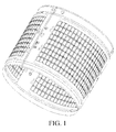
FIG. 1 is a schematic structural diagram of an inner barrel according to the present invention; -
FIG. 2 is a schematic structural diagram of a barrel wall of the inner barrel according to the present invention; -
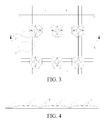
FIG. 3 is a locally enlarged diagram ofFIG. 2 ; -
FIG. 4 is a schematic expansion diagram of a cross section along a line a-a ofFIG. 3 . -
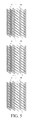
FIG. 5 is a schematic structural diagram of an exemplary barrel wall of an inner barrel; -
FIG. 6 is a locally enlarged diagram ofFIG. 5 ; -
FIG. 7 is a schematic structural diagram of a further exemplary barrel wall of an inner barrel; -
FIG. 8 is a locally enlarged diagram ofFIG. 7 ; -
FIG. 9 is a schematic diagram of a cross-section structure along a line M-M ofFIG. 8 ; and -
FIG. 10 is a schematic diagram of an exemplary cross-section structure along the line M-M ofFIG. 8 . - 1-Barrel wall; 2-Protrusion; 3-Dehydration hole; 4-Longitudinal flow channel; 5-Transverse flow channel; 21-First protrusion; and 22-Second protrusion
- The inner barrel described in the present invention is further described in detail with reference to
FIG. 1 to FIG. 4 . - As shown in
FIG. 1 andFIG. 2 , a washing machine inner barrel is provided, and a barrel wall 1 is provided with multiple pressed shapes arranged as a matrix and multiple dehydration holes 3 provided at a lowest part of the barrel wall 1. Each of the pressed shape is formed by a protrusion 2 directed to the inside of the inner barrel. The protrusion 2 is enclosed by a top surface and a blending surface. A bottom of the protrusion 2 is a rectangle connected by using arc chamfers, so that gaps between protrusions 2 in adjacent columns form straightlongitudinal flow channels 4, and gaps between protrusions 2 in adjacent rows form straighttransverse flow channels 5 perpendicular to thelongitudinal flow channels 4. The dehydration holes 3 are respectively provided at crossings of thetransverse flow channels 5 and thelongitudinal flow channels 4. - By means of the foregoing arrangement, during washing of a washing machine, water in the inner barrel flows along the straight
longitudinal flow channel 4 and/or thetransverse flow channel 5 to generate a water flow, and the water flow flows to an outer drum through the dehydration holes at the crossings. In this process, the water flow washes clothes. In this embodiment, the bottom of the protrusion 2 is a rectangle connected by using arc chamfers, or may be set to a square, a rhombus, or a parallelogram of any shape. - As shown in
FIG. 3 , the barrel wall 1 has multiple column lines that are parallel with an axial direction of the inner barrel and that are arranged in equal space: C-C, D-D, and the like, and is further provided with multiple row lines that are perpendicular to an axis of the inner barrel and that are arranged in equal space: A-A, B-B, and the like. The protrusion 2 is disposed at a crossing of each column line and each row line. The bottom of the protrusion 2 is a rectangle connected by using arc chamfers, and a center of the rectangle coincides with a crosspoint of the corresponding row line and column line. Therefore, pressed shapes formed by the protrusions are uniformly arranged as a matrix on the wall of the inner barrel. - As shown in
FIG. 3 and FIG. 4 , in this embodiment, the protrusion 2 is enclosed by a top surface and a blending surface with different curvatures, and the top surface and the blending surface are transitively connected smoothly. The top surface is a curved surface that becomes lower from a center of the protrusion to a circumference. The blending surface is a curved surface, where one end of the curved surface is transitively connected smoothly to the circumference of the top surface, and the other end is transitively connected smoothly to the barrel wall 1 through rounded corners. The blending surface is also a curved surface that becomes lower from the center of the protrusion center to the circumference, and a curvature radius of the blending surface is less than a curvature radius of the top surface. Therefore, each connecting line that is along an outer wall of the protrusion and that is from the center of the protrusion to any point on the bottom of the protrusion includes two arcs with different curvatures, and a surface of the protrusion has no edges, thereby reducing wear of clothes during a washing process of a washing machine. - In this embodiment, intersecting lines of the top surface and the blending surface form a rectangle that is different, in size, from the parallelogram connected to the arc chamfers at the bottom of the protrusion, but is the same in shape. In this embodiment, the intersecting lines of the top surface and the blending surface may also be set to a square, a rhombus, a parallelogram, a circle, or a geometry of any shape, but are exemplarily set to a shape that is different from the bottom of the protrusion in size but is the same in shape. Projected lines obtained by projecting the intersecting lines of the top surface and the blending surface onto the barrel wall all need to be set within a shape line of the bottom of the protrusion, to ensure that the blending surface gradually protrudes outwards from top to bottom.
- In this embodiment, each side edge of the rectangle at the bottom of the protrusion is set to a curve gradually protruding outwards from two ends to a center, so that a gap between adjacent protrusions narrows from the two ends to the middle, so that widths of the
longitudinal flow channel 4 and thetransverse flow channel 5 change, and the water flow flows through channels with different widths during a washing process, to achieve a scrubbing effect for clothes, and improving a washing effect. - In this embodiment, a connecting end of the blending surface and the top surface is an upper end of the blending surface, a connecting end of the blending surface and the barrel wall 1 is a lower end of the blending surface. The blending surface is formed by a square conic curved surface narrowing from bottom up. An upper end peripheral line of the conic curved surface is formed by a square peripheral line whose shape is the same as that of a peripheral line of the top surface, and a lower end peripheral line is formed by a square peripheral line that is different from the upper end peripheral line in size but is the same in shape. The upper end peripheral line and the lower end peripheral line are square peripheral lines having the same shape but different sizes, and arc chamfers are provided at four corners of the square peripheral line. A side corner of the blending surface is formed by an arc-shaped conic curved surface narrowing inwards and from bottom up, so that a periphery of the blending surface is enclosed by a smoothly transited curved surface, so as to reduce wear of washed clothes.
- In this embodiment, the blending surface is formed by a smooth curved surface whose upper and lower ends are respectively connected to the top surface and the barrel wall. The blending surface gradually bends outwards from up down, to form the curved surface smoothly extends outward from up down direction, and to make a distance between adjacent blending surfaces gradually narrow from up down, thereby forming a flow channel 3 gradually narrowing from up down between the adjacent protrusions 2.
- In this embodiment, a thickness of the barrel wall 1 is set to 0.3 mm to 1 mm, and is exemplarily set to 0.5 mm. A distance between the center of the protrusion 2 and the barrel wall 1 is a distance H, and a ratio of the distance H to the thickness of the barrel wall is set to 10:1 to 2:1. A ratio of a perimeter of the lower end peripheral line of the blending surface to a perimeter of the upper end peripheral line is 5:1 to 1.1:1.
- In this embodiment, the blending surface of the protrusion 2 is connected to the barrel wall 1 through arc chamfers, so that a bottom of the gap between the protrusions is formed by a horizontal plane, and two sides of the horizontal plane smoothly bend upwards, to form bottoms of the
longitudinal flow channel 4 and thetransverse flow channel 5. In this embodiment, because the side edge of the rectangle that forms the bottom edge of the protrusion is the curve gradually protruding outwards from the two ends to the middle, narrowest positions of thelongitudinal flow channel 4 and thetransverse flow channel 5 are centers of corresponding edges of the adjacent protrusions. A ratio of a width of the narrowest position of the flow channel to the thickness of the barrel wall is 10:1 to 1:4. - In this embodiment, the side corner of the blending surface is formed by the arc-shaped conic curved surface narrowing inwards and from bottom up, so that a dent whose bottom surface is a plane is formed at the crossing, enclosed by arc-shaped conic curved surfaces at corresponding side corners of four adjacent protrusions, of the
longitudinal flow channel 4 and thetransverse flow channel 5. A center of each dent center is provided with one circular dehydration hole 3. The dehydration hole 3 and a crosspoint of diagonal lines of top surfaces of four protrusions 2 are concentrically provided. A ratio of a diameter of the dehydration hole 3 to the thickness of the barrel wall 1 is set to 4:1 to 1:1. - Connections between the top surface and the blending surface of the protrusion and between the blending surface and the barrel wall are transited through smooth arcs, and the top surface and the blending surface are arc-shaped, so that there are no edges and corners that easily wear clothes out on the inner wall of the inner barrel, thereby reducing wear of clothes during a washing process.
- The protrusions arranged in columns and rows form a flow channel network formed by longitudinal and
transverse flow channels 5, and the dehydration hole 3 is provided at a crossing of each longitudinal andtransverse flow channel 5, so that during a drying process of a washing machine, water in an inner barrel is discharged out of the inner barrel through dehydration holes 3 that are provided at crossings and at the bottom of flow channels. - As shown in
FIG. 5 , a washing machine inner barrel is provided, and a barrel wall 1 is provided with multiple pressed shapes arranged in rows and in columns and multiple dehydration holes 3 provided at a lowest part of the barrel wall 1. Each of the pressed shape is formed by a protrusion 2 directed to the inside of the inner barrel. The protrusion 2 is enclosed by a top surface and a blending surface. Bottoms of protrusions 2 are formed by parallelograms that are the same in shape and in size, so that gaps between protrusions 2 in adjacent columns form straightlongitudinal flow channels 4, and gaps between protrusions 2 in adjacent rows form straighttransverse flow channels 5 crossing thelongitudinal flow channels 4. The dehydration holes 3 are respectively provided at crossings of thetransverse flow channels 5 and thelongitudinal flow channels 4. - As shown in
FIG. 6 , the barrel wall 1 has multiple row lines that are perpendicular to an axis of the inner barrel and that are arranged in equal space: E-E, F-F and the like, and is further provided with multiple column lines that has a same crossing angle to the row lines and that are arranged in equal space: G-G, K-K, and the like. The crossing angle of the row line and the column line is the same as an angle of adjacent edges forming the parallelogram of the protrusion. One protrusion 2 is disposed at the crossing of each column line and each row line. The bottom of the protrusion 2 is a parallelogram connected by using arc chamfers, and a center of the parallelogram coincides with a crosspoint of the corresponding row line and column line. Therefore, pressed shapes formed by the protrusions are uniformly arranged in rows and columns on the wall of the inner barrel. - In this embodiment, a parallelogram enclosed by four lines: E-E, F-F, G-G, and K-K is a minimum unit, and a protrusion 2 is disposed at each of crosspoints, which separately correspond to an EG protrusion, an EK protrusion, an FG protrusion, and an FK protrusion. A gap between the EG protrusion and the FG protrusion and a gap between the EK protrusion and the FK protrusion form a straight
transverse flow channel 5 for a water flow to pass, and a gap between the EG protrusion and the EK protrusion and a gap between the FG protrusion and the FK protrusion form a straightlongitudinal flow channel 4 for a water flow to pass. - In this embodiment, at least one dehydration hole 3 is provided at the crossing of the
longitudinal flow channel 4 andtransverse flow channel 5. When there are multiple dehydration holes 3, the dehydration hole 3 is symmetrically provided relatively to a center of the minimum unit center; or when there is one dehydration hole 3, a center of the dehydration hole 3 coincides with a center of the minimum unit. In this embodiment, exemplarily, two dehydration hole 3 are provided, and a center of the two dehydration holes 3 is disposed on a connecting line of a center of the EK protrusion and a center of the FG protrusion, and the two dehydration holes are symmetrical relatively to a connecting line of a center of the FK protrusion and a center of the EG protrusion. - In this embodiment, central connecting lines of adjacent protrusions that are neither in a same row nor in a same column are classified into acute connecting lines and obtuse connecting lines. The acute connecting line is a central connecting line of arc chamfers that passes through acute angles of adjacent edges of the parallelogram at the bottom of the protrusion, for example, the connecting line of the center of the EK protrusion and the center of the FG protrusion. The obtuse connecting line is a central connecting line of arc chamfers that passes through obtuse angles of adjacent edges of the parallelogram at the bottom of the protrusion, for example, the connecting line of the center of the FK protrusion and the center of the EG protrusion.
- In this embodiment, centers of the dehydration holes 3 are all provided on the acute connecting line, and the two dehydration holes 3 that are provided at the crossing of the same
longitudinal flow channel 4 and the sametransverse flow channel 5 are symmetrical relatively to the corresponding obtuse connecting line. - In this embodiment, intersecting lines of the top surface and the blending surface form a parallelogram that is different, in size, from the parallelogram connected to the arc chamfers at the bottom of the protrusion, but is the same in shape. In this embodiment, the intersecting lines of the top surface and the blending surface may also be set to a square, a rhombus, a parallelogram, a circle, or a geometry of any shape, but are exemplarily set to a shape that is different from the bottom of the protrusion in size but is the same in shape. Projected lines obtained by projecting the intersecting lines of the top surface and the blending surface onto the barrel wall all need to be set within a shape line of the bottom of the protrusion, to ensure that the blending surface gradually protrudes outwards from top to bottom.
- As shown in
FIG. 7 , a washing machine inner barrel is provided, and a barrel wall 1 is provided with multiple pressed shapes arranged in rows and in columns and multiple dehydration holes 3 provided at a lowest part of the barrel wall 1. Each of the pressed shape is formed by a protrusion directed to the inside of the inner barrel. Protrusions includefirst protrusions 21 andsecond protrusions 22. Bottoms of thefirst protrusion 21 and thesecond protrusion 22 are both formed by parallelograms that are the same in shape but are different in size. Thefirst protrusions 21 and thesecond protrusions 22 are arranged across each other, so that gaps between protrusions 2 in adjacent columns form straightlongitudinal flow channels 4 whose two side walls: a left side wall and a right wall intersect and expand outwards, and gaps between protrusions 2 in adjacent rows form straighttransverse flow channels 5 that are perpendicular to thelongitudinal flow channels 4 and whose two side walls: a left side wall and a right wall intersect and expand outwards. The dehydration holes 3 are respectively provided at crossings of thetransverse flow channels 5 and thelongitudinal flow channels 4. - As shown in
FIG. 8 , the barrel wall 1 has multiple row lines that are perpendicular to an axis of the inner barrel and that are arranged in equal space: L-L, M-M, N-N, and the like, and further provided with multiple column lines that have a same crossing angle to the row lines and that are arranged in equal space: H-H, P-P, Q-Q, I-I, and the like. One protrusion 2 is disposed at a crossing of each column line and each row line.First protrusions 21 andsecond protrusions 22 are separately spaced in a same column and in a same row, and are disposed in manner that their centers are in equal space. The centers of thefirst protrusion 21 and thesecond protrusion 22 separately coincide with crossings of corresponding row lines and column lines. - As shown in
FIG. 9 , in this embodiment, distances from central points of thefirst protrusion 21 and thesecond protrusion 21 to the barrel wall 1 are equal. The protrusions with different sizes are spaced, so that a water flow in a sametransverse flow channel 5 and in a samelongitudinal flow channel 4 moves left and right, and a speed of the water flow changes, thereby achieving a washing effect of beating clothes by changing a water flow in an inner barrel. - Values of height from the central points of the first protrusion and the second protrusion to the barrel wall may also be set to different values. As shown in
FIG. 10 , a ratio of a distance between a central point of thefirst protrusion 21 and the barrel wall to a distance between a central point of thesecond protrusion 22 and the barrel wall 1 is 2:1. Therefore, a surface of the inner wall of the inner barrel forms a convex and concave wavy surface, so that clothes in the inner barrel rubbing the wall of the inner barrel during a working process of a washing machine, thereby improving washing efficiency of the washing machine. - The present invention is not limited to the foregoing examples, obvious technical solutions and various modifications and changes made to the embodiments of the present invention by a person of ordinary skill in the art without departing from the spirit and scope of the present invention shall fall within the claims of the present invention and the equivalent replacements thereof.
Claims (10)
- A washing machine inner barrel, a barrel wall (1) being provided with multiple pressed shapes and multiple dehydration holes (3), wherein the pressed shapes are formed by protrusions (2) directed to the inside of the inner barrel, a bottom of the protrusion (2) is a parallelogram, and the protrusions are arranged in rows and columns; and gaps between protrusions (2) that are in adjacent columns and in adjacent rows form straight flow channels for a water flow to pass, and the dehydration hole (3) is provided on the straight flow channel.
- The washing machine inner barrel according to claim 1, wherein the bottom of each protrusion (2) is formed by a parallelogram of a same shape, and the parallelogram is a rectangle, a square, a rhombus or a parallelogram whose adjacent edges are not equal.
- The washing machine inner barrel according to claim 2, wherein a center line of protrusions (2) in a same column perpendicularly intersects with a center line of protrusions in a same row.
- The washing machine inner barrel according to claim 1, wherein distances between adjacent protrusions (2) in a same column and in a same row are equal.
- The washing machine inner barrel according to claim 1, wherein the protrusion (2) is formed by a top surface and a blending surface with different curvatures, so that each connecting line that is along an outer wall of the protrusion and that is from a protrusion center to any point on the bottom of the protrusion comprises two arcs with different curvatures.
- The washing machine inner barrel according to claim 1, wherein intersecting lines of a top surface and a blending surface form a parallelogram that is different from the parallelogram at the bottom of the protrusion in size, and a length and a width of the parallelogram that is formed by the intersecting lines of the two curved surfaces are less than a length and a width of the parallelogram at the bottom of the protrusion.
- The washing machine inner barrel according to claim 5, wherein adjacent side edges of a parallelogram formed by the bottom of the protrusion (2) and by intersecting lines of the two curved surfaces are transitively connected by through rounded corners.
- The washing machine inner barrel according to claim 6, wherein a side edge of the parallelogram gradually bends outwards from two ends to the middle.
- The washing machine inner barrel according to claim 1, wherein the straight flow channels form a flow channel network that is formed by crossing multiple transverse flow channels (5) disposed in parallel over multiple longitudinal flow channels (4) disposed in parallel; and the dehydration holes (3) are respectively provided at crossings of the transverse flow channels (5) and the longitudinal flow channels (4).
- A washing machine, wherein the inner barrel according to any one of claims 1 to 9 is disposed in the washing machine.
Applications Claiming Priority (2)
| Application Number | Priority Date | Filing Date | Title |
|---|---|---|---|
| CN201310385780.1A CN104420124B (en) | 2013-08-29 | 2013-08-29 | A kind of washing machine inner tub and washing machine |
| PCT/CN2013/001637 WO2015027368A1 (en) | 2013-08-29 | 2013-12-24 | Washing machine inner barrel and washing machine |
Publications (3)
| Publication Number | Publication Date |
|---|---|
| EP3040466A1 true EP3040466A1 (en) | 2016-07-06 |
| EP3040466A4 EP3040466A4 (en) | 2016-08-24 |
| EP3040466B1 EP3040466B1 (en) | 2018-06-27 |
Family
ID=52585358
Family Applications (1)
| Application Number | Title | Priority Date | Filing Date |
|---|---|---|---|
| EP13892710.8A Active EP3040466B1 (en) | 2013-08-29 | 2013-12-24 | Washing machine inner barrel and washing machine |
Country Status (6)
| Country | Link |
|---|---|
| US (1) | US20160215431A1 (en) |
| EP (1) | EP3040466B1 (en) |
| JP (1) | JP6296261B2 (en) |
| KR (1) | KR101962253B1 (en) |
| CN (1) | CN104420124B (en) |
| WO (1) | WO2015027368A1 (en) |
Families Citing this family (9)
| Publication number | Priority date | Publication date | Assignee | Title |
|---|---|---|---|---|
| JP2016187450A (en) * | 2015-03-30 | 2016-11-04 | 東芝ライフスタイル株式会社 | Drum-type washing machine |
| CN105063962B (en) * | 2015-08-05 | 2018-09-18 | 合肥美的洗衣机有限公司 | Washing machine |
| CN106637819A (en) * | 2016-10-19 | 2017-05-10 | 珠海格力电器股份有限公司 | Washing machine inner barrel and washing machine comprising same |
| CN109208249A (en) * | 2017-07-07 | 2019-01-15 | 青岛海尔洗衣机有限公司 | A kind of inner tank of washing machine and washing machine |
| CN107385780A (en) * | 2017-08-10 | 2017-11-24 | 荣嫚丽 | A kind of dehydrating vessel in washing machine |
| WO2020140884A1 (en) * | 2019-01-02 | 2020-07-09 | 青岛海尔滚筒洗衣机有限公司 | Front-loading washing machine and control method thereof |
| EP3715522B1 (en) * | 2019-03-26 | 2022-05-11 | Electrolux Appliances Aktiebolag | Washing drum for a laundry washing machine and laundry washing machine equipped with such drum |
| KR102742321B1 (en) | 2019-08-23 | 2024-12-12 | 삼성전자주식회사 | Drum type laundry apparatus |
| CN115538105B (en) * | 2021-06-30 | 2026-01-27 | 无锡小天鹅电器有限公司 | Washing drum and laundry treatment apparatus having the same |
Family Cites Families (15)
| Publication number | Priority date | Publication date | Assignee | Title |
|---|---|---|---|---|
| JPS54120958A (en) * | 1978-03-13 | 1979-09-19 | Hitachi Ltd | Washing tank in washing machine doubling as dehydration |
| JP3265863B2 (en) * | 1994-10-28 | 2002-03-18 | 株式会社日立製作所 | Washing machine |
| DE10162918A1 (en) | 2001-12-20 | 2003-07-03 | Bsh Bosch Siemens Hausgeraete | Drum for a laundry treatment machine |
| ES2362002T3 (en) * | 2006-11-24 | 2011-06-27 | Whirlpool Corporation | DRUM FOR A WASHING MACHINE AND WASHING MACHINE PROVIDED WITH SUCH DRUM. |
| KR101136863B1 (en) * | 2007-02-28 | 2012-04-20 | 삼성전자주식회사 | Washing machine |
| ES2642871T3 (en) * | 2007-11-12 | 2017-11-20 | Tulga Simsek | Washer-extractor |
| DE102008004661A1 (en) * | 2008-01-16 | 2009-07-23 | BSH Bosch und Siemens Hausgeräte GmbH | Drum for a laundry treatment machine |
| JP4620137B2 (en) * | 2008-03-12 | 2011-01-26 | 株式会社東芝 | Washing machine |
| CN101845739B (en) * | 2009-03-23 | 2013-08-07 | 海尔集团公司 | Inner drum of washing machine with high-efficient washing and dehydration structure |
| CN201447586U (en) * | 2009-06-18 | 2010-05-05 | Tcl家用电器(惠州)有限公司 | Washing machine inner barrel structure |
| PL2390399T3 (en) * | 2010-05-31 | 2013-04-30 | Miele & Cie | Drum for a washing machine |
| EP2628839A1 (en) * | 2012-02-18 | 2013-08-21 | Samsung Electronics Co., Ltd | Washing machine |
| JP5326034B2 (en) * | 2012-09-28 | 2013-10-30 | 日立アプライアンス株式会社 | Washing machine |
| CN102912592B (en) * | 2012-09-29 | 2017-02-08 | 青岛海尔洗衣机有限公司 | Inner barrel of fully automatic washing machine and washing machine utilizing inner barrel |
| CN202969066U (en) * | 2012-12-05 | 2013-06-05 | 中山东菱威力电器有限公司 | A washing machine inner tub |
-
2013
- 2013-08-29 CN CN201310385780.1A patent/CN104420124B/en active Active
- 2013-12-24 JP JP2016537062A patent/JP6296261B2/en active Active
- 2013-12-24 KR KR1020167005838A patent/KR101962253B1/en active Active
- 2013-12-24 EP EP13892710.8A patent/EP3040466B1/en active Active
- 2013-12-24 US US14/914,549 patent/US20160215431A1/en not_active Abandoned
- 2013-12-24 WO PCT/CN2013/001637 patent/WO2015027368A1/en not_active Ceased
Also Published As
| Publication number | Publication date |
|---|---|
| WO2015027368A1 (en) | 2015-03-05 |
| EP3040466A4 (en) | 2016-08-24 |
| US20160215431A1 (en) | 2016-07-28 |
| CN104420124A (en) | 2015-03-18 |
| CN104420124B (en) | 2018-05-22 |
| JP2016540574A (en) | 2016-12-28 |
| KR101962253B1 (en) | 2019-03-26 |
| EP3040466B1 (en) | 2018-06-27 |
| JP6296261B2 (en) | 2018-03-20 |
| KR20160043976A (en) | 2016-04-22 |
Similar Documents
| Publication | Publication Date | Title |
|---|---|---|
| EP3040466B1 (en) | Washing machine inner barrel and washing machine | |
| CN1608157B (en) | Drum of a washing machine with an arched structure pointing into the drum | |
| US20190374913A1 (en) | Stirred tank | |
| CN209116451U (en) | A kind of air-conditioner outdoor unit air outlet grate denoising structure | |
| CN102912592B (en) | Inner barrel of fully automatic washing machine and washing machine utilizing inner barrel | |
| CN108823913A (en) | A kind of swirl washing machine external barrel lid and rotary drum washing machine | |
| CN206882252U (en) | Nozzle and the novel foam wash mill using the nozzle | |
| CN211475128U (en) | High-strength corrugated pipe with novel structure wall | |
| CN106149318B (en) | Washing/drying machine observation window and washing/drying machine | |
| CN115538105B (en) | Washing drum and laundry treatment apparatus having the same | |
| WO2023273288A1 (en) | Washing drum and laundry treatment apparatus having same | |
| CN104706296A (en) | Spray arm structure for dish-washing machine | |
| CN111839410B (en) | Dishwasher filter structure and dishwasher | |
| CN105220404A (en) | Washing machine and inner core thereof | |
| CN205954343U (en) | Washing machine's inner tube and washing machine | |
| KR20220032019A (en) | drum of the washing machine | |
| CN223991193U (en) | Door seal and clothes treatment device | |
| CN109797520B (en) | Inner barrel of washing machine and washing machine | |
| CN110360152B (en) | Axial flow fan blade and air conditioner | |
| CN204491306U (en) | A kind of papermaking profiled sheeting | |
| CN217610933U (en) | Mop bottom plate and mop thereof | |
| EP3187649B1 (en) | Washing machine sprayer apparatus and drum washing machine having the same | |
| CN206588127U (en) | A kind of lower block bucket of glass cleaning drier | |
| CN2334682Y (en) | Container bottle | |
| CN207045924U (en) | A reinforced structure and bottle |
Legal Events
| Date | Code | Title | Description |
|---|---|---|---|
| PUAI | Public reference made under article 153(3) epc to a published international application that has entered the european phase |
Free format text: ORIGINAL CODE: 0009012 |
|
| 17P | Request for examination filed |
Effective date: 20160226 |
|
| AK | Designated contracting states |
Kind code of ref document: A1 Designated state(s): AL AT BE BG CH CY CZ DE DK EE ES FI FR GB GR HR HU IE IS IT LI LT LU LV MC MK MT NL NO PL PT RO RS SE SI SK SM TR |
|
| AX | Request for extension of the european patent |
Extension state: BA ME |
|
| A4 | Supplementary search report drawn up and despatched |
Effective date: 20160725 |
|
| RIC1 | Information provided on ipc code assigned before grant |
Ipc: D06F 37/06 20060101ALI20160715BHEP Ipc: D06F 37/02 20060101AFI20160715BHEP |
|
| DAX | Request for extension of the european patent (deleted) | ||
| 17Q | First examination report despatched |
Effective date: 20170714 |
|
| GRAP | Despatch of communication of intention to grant a patent |
Free format text: ORIGINAL CODE: EPIDOSNIGR1 |
|
| INTG | Intention to grant announced |
Effective date: 20180320 |
|
| GRAS | Grant fee paid |
Free format text: ORIGINAL CODE: EPIDOSNIGR3 |
|
| GRAA | (expected) grant |
Free format text: ORIGINAL CODE: 0009210 |
|
| AK | Designated contracting states |
Kind code of ref document: B1 Designated state(s): AL AT BE BG CH CY CZ DE DK EE ES FI FR GB GR HR HU IE IS IT LI LT LU LV MC MK MT NL NO PL PT RO RS SE SI SK SM TR |
|
| REG | Reference to a national code |
Ref country code: GB Ref legal event code: FG4D |
|
| REG | Reference to a national code |
Ref country code: AT Ref legal event code: REF Ref document number: 1012448 Country of ref document: AT Kind code of ref document: T Effective date: 20180715 |
|
| REG | Reference to a national code |
Ref country code: IE Ref legal event code: FG4D |
|
| REG | Reference to a national code |
Ref country code: DE Ref legal event code: R096 Ref document number: 602013039576 Country of ref document: DE |
|
| PG25 | Lapsed in a contracting state [announced via postgrant information from national office to epo] |
Ref country code: BG Free format text: LAPSE BECAUSE OF FAILURE TO SUBMIT A TRANSLATION OF THE DESCRIPTION OR TO PAY THE FEE WITHIN THE PRESCRIBED TIME-LIMIT Effective date: 20180927 Ref country code: NO Free format text: LAPSE BECAUSE OF FAILURE TO SUBMIT A TRANSLATION OF THE DESCRIPTION OR TO PAY THE FEE WITHIN THE PRESCRIBED TIME-LIMIT Effective date: 20180927 Ref country code: LT Free format text: LAPSE BECAUSE OF FAILURE TO SUBMIT A TRANSLATION OF THE DESCRIPTION OR TO PAY THE FEE WITHIN THE PRESCRIBED TIME-LIMIT Effective date: 20180627 Ref country code: SE Free format text: LAPSE BECAUSE OF FAILURE TO SUBMIT A TRANSLATION OF THE DESCRIPTION OR TO PAY THE FEE WITHIN THE PRESCRIBED TIME-LIMIT Effective date: 20180627 Ref country code: FI Free format text: LAPSE BECAUSE OF FAILURE TO SUBMIT A TRANSLATION OF THE DESCRIPTION OR TO PAY THE FEE WITHIN THE PRESCRIBED TIME-LIMIT Effective date: 20180627 |
|
| REG | Reference to a national code |
Ref country code: NL Ref legal event code: MP Effective date: 20180627 |
|
| REG | Reference to a national code |
Ref country code: LT Ref legal event code: MG4D |
|
| PG25 | Lapsed in a contracting state [announced via postgrant information from national office to epo] |
Ref country code: LV Free format text: LAPSE BECAUSE OF FAILURE TO SUBMIT A TRANSLATION OF THE DESCRIPTION OR TO PAY THE FEE WITHIN THE PRESCRIBED TIME-LIMIT Effective date: 20180627 Ref country code: HR Free format text: LAPSE BECAUSE OF FAILURE TO SUBMIT A TRANSLATION OF THE DESCRIPTION OR TO PAY THE FEE WITHIN THE PRESCRIBED TIME-LIMIT Effective date: 20180627 Ref country code: RS Free format text: LAPSE BECAUSE OF FAILURE TO SUBMIT A TRANSLATION OF THE DESCRIPTION OR TO PAY THE FEE WITHIN THE PRESCRIBED TIME-LIMIT Effective date: 20180627 Ref country code: GR Free format text: LAPSE BECAUSE OF FAILURE TO SUBMIT A TRANSLATION OF THE DESCRIPTION OR TO PAY THE FEE WITHIN THE PRESCRIBED TIME-LIMIT Effective date: 20180928 |
|
| REG | Reference to a national code |
Ref country code: AT Ref legal event code: MK05 Ref document number: 1012448 Country of ref document: AT Kind code of ref document: T Effective date: 20180627 |
|
| PG25 | Lapsed in a contracting state [announced via postgrant information from national office to epo] |
Ref country code: NL Free format text: LAPSE BECAUSE OF FAILURE TO SUBMIT A TRANSLATION OF THE DESCRIPTION OR TO PAY THE FEE WITHIN THE PRESCRIBED TIME-LIMIT Effective date: 20180627 |
|
| PG25 | Lapsed in a contracting state [announced via postgrant information from national office to epo] |
Ref country code: EE Free format text: LAPSE BECAUSE OF FAILURE TO SUBMIT A TRANSLATION OF THE DESCRIPTION OR TO PAY THE FEE WITHIN THE PRESCRIBED TIME-LIMIT Effective date: 20180627 Ref country code: PL Free format text: LAPSE BECAUSE OF FAILURE TO SUBMIT A TRANSLATION OF THE DESCRIPTION OR TO PAY THE FEE WITHIN THE PRESCRIBED TIME-LIMIT Effective date: 20180627 Ref country code: SK Free format text: LAPSE BECAUSE OF FAILURE TO SUBMIT A TRANSLATION OF THE DESCRIPTION OR TO PAY THE FEE WITHIN THE PRESCRIBED TIME-LIMIT Effective date: 20180627 Ref country code: CZ Free format text: LAPSE BECAUSE OF FAILURE TO SUBMIT A TRANSLATION OF THE DESCRIPTION OR TO PAY THE FEE WITHIN THE PRESCRIBED TIME-LIMIT Effective date: 20180627 Ref country code: RO Free format text: LAPSE BECAUSE OF FAILURE TO SUBMIT A TRANSLATION OF THE DESCRIPTION OR TO PAY THE FEE WITHIN THE PRESCRIBED TIME-LIMIT Effective date: 20180627 Ref country code: IS Free format text: LAPSE BECAUSE OF FAILURE TO SUBMIT A TRANSLATION OF THE DESCRIPTION OR TO PAY THE FEE WITHIN THE PRESCRIBED TIME-LIMIT Effective date: 20181027 Ref country code: AT Free format text: LAPSE BECAUSE OF FAILURE TO SUBMIT A TRANSLATION OF THE DESCRIPTION OR TO PAY THE FEE WITHIN THE PRESCRIBED TIME-LIMIT Effective date: 20180627 |
|
| PG25 | Lapsed in a contracting state [announced via postgrant information from national office to epo] |
Ref country code: SM Free format text: LAPSE BECAUSE OF FAILURE TO SUBMIT A TRANSLATION OF THE DESCRIPTION OR TO PAY THE FEE WITHIN THE PRESCRIBED TIME-LIMIT Effective date: 20180627 Ref country code: ES Free format text: LAPSE BECAUSE OF FAILURE TO SUBMIT A TRANSLATION OF THE DESCRIPTION OR TO PAY THE FEE WITHIN THE PRESCRIBED TIME-LIMIT Effective date: 20180627 |
|
| REG | Reference to a national code |
Ref country code: DE Ref legal event code: R097 Ref document number: 602013039576 Country of ref document: DE |
|
| PLBE | No opposition filed within time limit |
Free format text: ORIGINAL CODE: 0009261 |
|
| STAA | Information on the status of an ep patent application or granted ep patent |
Free format text: STATUS: NO OPPOSITION FILED WITHIN TIME LIMIT |
|
| PG25 | Lapsed in a contracting state [announced via postgrant information from national office to epo] |
Ref country code: DK Free format text: LAPSE BECAUSE OF FAILURE TO SUBMIT A TRANSLATION OF THE DESCRIPTION OR TO PAY THE FEE WITHIN THE PRESCRIBED TIME-LIMIT Effective date: 20180627 |
|
| 26N | No opposition filed |
Effective date: 20190328 |
|
| REG | Reference to a national code |
Ref country code: CH Ref legal event code: PL |
|
| PG25 | Lapsed in a contracting state [announced via postgrant information from national office to epo] |
Ref country code: SI Free format text: LAPSE BECAUSE OF FAILURE TO SUBMIT A TRANSLATION OF THE DESCRIPTION OR TO PAY THE FEE WITHIN THE PRESCRIBED TIME-LIMIT Effective date: 20180627 Ref country code: LU Free format text: LAPSE BECAUSE OF NON-PAYMENT OF DUE FEES Effective date: 20181224 Ref country code: MC Free format text: LAPSE BECAUSE OF FAILURE TO SUBMIT A TRANSLATION OF THE DESCRIPTION OR TO PAY THE FEE WITHIN THE PRESCRIBED TIME-LIMIT Effective date: 20180627 |
|
| REG | Reference to a national code |
Ref country code: IE Ref legal event code: MM4A |
|
| REG | Reference to a national code |
Ref country code: BE Ref legal event code: MM Effective date: 20181231 |
|
| PG25 | Lapsed in a contracting state [announced via postgrant information from national office to epo] |
Ref country code: IE Free format text: LAPSE BECAUSE OF NON-PAYMENT OF DUE FEES Effective date: 20181224 |
|
| PG25 | Lapsed in a contracting state [announced via postgrant information from national office to epo] |
Ref country code: BE Free format text: LAPSE BECAUSE OF NON-PAYMENT OF DUE FEES Effective date: 20181231 Ref country code: AL Free format text: LAPSE BECAUSE OF FAILURE TO SUBMIT A TRANSLATION OF THE DESCRIPTION OR TO PAY THE FEE WITHIN THE PRESCRIBED TIME-LIMIT Effective date: 20180627 |
|
| PG25 | Lapsed in a contracting state [announced via postgrant information from national office to epo] |
Ref country code: LI Free format text: LAPSE BECAUSE OF NON-PAYMENT OF DUE FEES Effective date: 20181231 Ref country code: CH Free format text: LAPSE BECAUSE OF NON-PAYMENT OF DUE FEES Effective date: 20181231 |
|
| PG25 | Lapsed in a contracting state [announced via postgrant information from national office to epo] |
Ref country code: MT Free format text: LAPSE BECAUSE OF NON-PAYMENT OF DUE FEES Effective date: 20181224 |
|
| PG25 | Lapsed in a contracting state [announced via postgrant information from national office to epo] |
Ref country code: TR Free format text: LAPSE BECAUSE OF FAILURE TO SUBMIT A TRANSLATION OF THE DESCRIPTION OR TO PAY THE FEE WITHIN THE PRESCRIBED TIME-LIMIT Effective date: 20180627 |
|
| PG25 | Lapsed in a contracting state [announced via postgrant information from national office to epo] |
Ref country code: PT Free format text: LAPSE BECAUSE OF FAILURE TO SUBMIT A TRANSLATION OF THE DESCRIPTION OR TO PAY THE FEE WITHIN THE PRESCRIBED TIME-LIMIT Effective date: 20180627 |
|
| PG25 | Lapsed in a contracting state [announced via postgrant information from national office to epo] |
Ref country code: HU Free format text: LAPSE BECAUSE OF FAILURE TO SUBMIT A TRANSLATION OF THE DESCRIPTION OR TO PAY THE FEE WITHIN THE PRESCRIBED TIME-LIMIT; INVALID AB INITIO Effective date: 20131224 Ref country code: MK Free format text: LAPSE BECAUSE OF NON-PAYMENT OF DUE FEES Effective date: 20180627 Ref country code: CY Free format text: LAPSE BECAUSE OF FAILURE TO SUBMIT A TRANSLATION OF THE DESCRIPTION OR TO PAY THE FEE WITHIN THE PRESCRIBED TIME-LIMIT Effective date: 20180627 |
|
| PGFP | Annual fee paid to national office [announced via postgrant information from national office to epo] |
Ref country code: DE Payment date: 20251211 Year of fee payment: 13 |
|
| PGFP | Annual fee paid to national office [announced via postgrant information from national office to epo] |
Ref country code: GB Payment date: 20251219 Year of fee payment: 13 |
|
| PGFP | Annual fee paid to national office [announced via postgrant information from national office to epo] |
Ref country code: IT Payment date: 20251223 Year of fee payment: 13 |
|
| PGFP | Annual fee paid to national office [announced via postgrant information from national office to epo] |
Ref country code: FR Payment date: 20251223 Year of fee payment: 13 |