EP3040159A1 - Grinder - Google Patents
Grinder Download PDFInfo
- Publication number
- EP3040159A1 EP3040159A1 EP14839714.4A EP14839714A EP3040159A1 EP 3040159 A1 EP3040159 A1 EP 3040159A1 EP 14839714 A EP14839714 A EP 14839714A EP 3040159 A1 EP3040159 A1 EP 3040159A1
- Authority
- EP
- European Patent Office
- Prior art keywords
- attachment base
- wheel guard
- mating
- spindle
- protruding portion
- Prior art date
- Legal status (The legal status is an assumption and is not a legal conclusion. Google has not performed a legal analysis and makes no representation as to the accuracy of the status listed.)
- Withdrawn
Links
Images



Classifications
-
- B—PERFORMING OPERATIONS; TRANSPORTING
- B24—GRINDING; POLISHING
- B24B—MACHINES, DEVICES, OR PROCESSES FOR GRINDING OR POLISHING; DRESSING OR CONDITIONING OF ABRADING SURFACES; FEEDING OF GRINDING, POLISHING, OR LAPPING AGENTS
- B24B55/00—Safety devices for grinding or polishing machines; Accessories fitted to grinding or polishing machines for keeping tools or parts of the machine in good working condition
- B24B55/04—Protective covers for the grinding wheel
- B24B55/05—Protective covers for the grinding wheel specially designed for portable grinding machines
- B24B55/052—Protective covers for the grinding wheel specially designed for portable grinding machines with rotating tools
-
- B—PERFORMING OPERATIONS; TRANSPORTING
- B24—GRINDING; POLISHING
- B24B—MACHINES, DEVICES, OR PROCESSES FOR GRINDING OR POLISHING; DRESSING OR CONDITIONING OF ABRADING SURFACES; FEEDING OF GRINDING, POLISHING, OR LAPPING AGENTS
- B24B23/00—Portable grinding machines, e.g. hand-guided; Accessories therefor
- B24B23/02—Portable grinding machines, e.g. hand-guided; Accessories therefor with rotating grinding tools; Accessories therefor
- B24B23/028—Angle tools
Definitions
- the present invention relates to a grinder to which a rotating tool is attached.
- a grinder is provided with a spindle, which is subjected to a rotary drive, and various rotating tools are attached to the spindle depending on purposes and uses.
- a disk-shaped grinding stone, a brush, a cutter, etc. are attached to the spindle of the grinder.
- the grinding stone to be attached to the spindle of the grinder includes a grinding stone for polishing and a grinding stone for cutting.
- the brush to be attached to the spindle of the grinder includes a wire brush and a wireless brush.
- the cutter to be attached to the spindle of the grinder includes a diamond cutter.
- various rotating tools attached to the spindle may be collectively referred to as "wheel”.
- the grinder as described above is required to attach a wheel guard that covers 1/2 or more the outer circumference of the wheel. Moreover, when the grinder is used, the attachment position of the wheel guard has to be changed depending on purposes and uses.
- Patent Document 1 describes a grinder in which the attachment position of the wheel guard can be changed without using a tool such as a wrench or a screwdriver.
- the wheel guard is turnably attached to a packing gland.
- the packing gland is provided with a retaining groove, and a set ring of the wheel guard is provided with a rib, which is mated with the retaining groove.
- a coiled spring which prevents the rib mated with the retaining groove from falling, is disposed.
- Patent Document 1 Japanese Utility Model Application Publication Laid-Open No. H6(1994)-36764
- An object of the present invention is to reduce, as much as possible, the possibility that the fixation of the wheel guard is cancelled against the intention of the operator.
- a grinder of the present invention is provided with a spindle to which a rotating tool is attached and a wheel guard covering the rotating tool attached to the spindle, and the grinder includes: an attachment base provided on a main body rotatably retaining the spindle, the attachment base surrounding the spindle; a mating portion provided on the wheel guard and mated with the attachment base; a recessed portion provided on either one of the attachment base and the mating portion; and a protruding portion provided on the other one of the attachment base and the mating portion. Then, when the wheel guard is displaced in a radial direction of the spindle, mating between the recessed portion and the protruding portion is cancelled, and the wheel guard is turnable in a circumferential direction of the spindle.
- the grinder is provided with an elastic body disposed between the attachment base and the mating portion, and when the wheel guard is displaced in a radial direction of the spindle against bias of the elastic body, the mating between the recessed portion and the protruding portion is cancelled, and the wheel guard is turnable in the circumferential direction of the spindle.
- the recessed portion is provided on an outer circumferential surface of the attachment base
- the protruding portion is provided on an inner circumferential surface of the mating portion
- the elastic body is provided on the inner circumferential surface of the mating portion and at a position opposed to the protruding portion.
- the elastic body is a plate spring curved toward an inner side of the mating portion.
- the main body includes: a housing housing a drive source of the spindle; and a gear case rotatably retaining the spindle.
- the attachment base is integrally formed with a cover member covering an opening of the gear case.
- the grinder is provided with a projecting portion projecting inward from the inner circumferential surface of the mating portion, and an engaging portion projecting outward from the outer circumferential surface of the attachment base and engaged with the projecting portion.
- the recessed portion is provided on the attachment base, and the engaging portion is provided in a region of the attachment base excluding a region in which the recessed portion is provided.
- a grinder is provided with an output shaft to which a rotating tool is attached, a wheel guard covering the rotating tool, and an attachment base to which the wheel guard is attached, and the grinder includes: a recessed portion provided on either one of the wheel guard and the attachment base; and a protruding portion provided on the other one of the wheel guard and the attachment base. Then, the recessed portion and the protruding portion are mated with each other in a radial direction of the output shaft.
- the grinder is provided with an elastic body disposed between the wheel guard and the attachment base in the radial direction of the output shaft, and biasing either one of the protruding portion and the recessed portion toward the other one of the protruding portion and the recessed portion.
- the wheel guard is provided with either one of the protruding portion and the recessed portion, the elastic body, and a perpendicular part covering a radial-direction outer side of the rotating tool.
- the perpendicular part is provided in a side in which the elastic body is provided in relation with the output shaft.
- either one of the protruding portion and the recessed portion, and the elastic body are provided at symmetrical positions with respect to the output shaft.
- a grinder in another aspect of the present invention, includes: an output shaft to which a rotating tool is attached; a wheel guard provided with a mating portion and a perpendicular part covering the rotating tool; and an attachment base to which the mating portion is attached.
- the wheel guard is movable from the mating-portion side to the perpendicular-part side, and the mating portion and the attachment base are mated with each other in a moving direction of the wheel guard.
- the grinder is provided with a recessed portion provided on either one of the mating portion and the attachment base, and a protruding portion provided on the other one of the mating portion and the attachment base.
- the recessed portion and the protruding portion are disposed in an opposite side of the perpendicular part with respect to the output shaft.
- the grinder is provided with an elastic body biasing the wheel guard to the perpendicular-part side.
- the grinder is provided with an elastic body causing the recessed portion and the protruding portion to be mated with each other in a radial direction of the output shaft.
- the possibility that the fixation of the wheel guard is cancelled against the intention of the operator is reduced.
- a grinder 1 As shown in FIG. 1 , a grinder 1 according to the present embodiment is provided with a diamond grinding wheel (hereinafter, referred to as "grinding wheel 2".) serving as a rotating tool and is used in, for example, a grinding operation of planarizing the surfaces of concrete, stone, etc.
- grinding wheel 2 a diamond grinding wheel serving as a rotating tool and is used in, for example, a grinding operation of planarizing the surfaces of concrete, stone, etc.
- the grinder 1 is provided with a main body 5 including a housing 3 and a gear case 4.
- the housing 3 has an approximately cylindrical shape as a whole, and an electric motor 6 serving as a drive source is housed in the housing 3.
- the electric motor 6 is connected to a commercial electric-power source via an electric-power-source cord 7, which is extended from a rear end of the housing 3.
- the gear case 4 has a case main body 10 and a packing gland 11 serving as a cover member, which covers an opening of the case main body 10, and is attached to a distal end of the housing 3.
- Two bearings (a needle bearing 12 and a ball bearing 13) are provided in the gear case 4, and a spindle (output shaft) 20 is rotatably retained by these bearings.
- the spindle 20 is orthogonal to an output shaft 6a of the electric motor 6, and one end thereof is penetrating through the packing gland 11 and projecting to the outside.
- a bevel gear 22, which is meshed with a bevel gear 21 attached to the output shaft 6a of the electric motor 6, is attached to the other end of the spindle 20 positioned in the gear case 4.
- the rotation direction of the electric motor 6 is converted by 90 degrees by the above-described pair of bevel gears and is transmitted to the spindle 20 with a reduced rotation speed.
- the spindle 20 is subjected to rotary drive by the electric motor 6.
- the grinding wheel 2 is provided with a substrate 2a including a disk-shaped steel plate, and a plurality of diamond grinding stones are fixed to a surface of the substrate 2a by adhesion or another means. Moreover, an attachment hole into which the spindle 20 is inserted is provided at the center of the substrate 2a, and the grinding wheel 2 is attached to the spindle 20, which penetrates through the attachment hole. Specifically, the grinding wheel 2 is fixed to the spindle 20 by a wheel washer (s) and a lock nut(s), and rotated integrally with the spindle 20.
- the housing 3 is provided with an unshown switch. When this switch is operated, electric power is supplied to the electric motor 6, and the output shaft 6a of the electric motor 6 is rotated. As a result, the spindle 20 coupled to the output shaft 6a via the above-described pair of bevel gears is rotated, and the grinding wheel 2 fixed to the spindle 20 is rotated.
- a wheel guard 30 covering at least 1/2 or more the outer circumference of the grinding wheel 2 is attached to the gear case 4.
- an attachment structure of the wheel guard 30 will be explained in detail.
- a through hole 40 through which the spindle 20 ( FIG. 1 ) penetrates is provided at the center of the packing gland 11.
- a tubular attachment base 41 is integrally formed with a lower surface of the packing gland 11.
- the attachment base 41 is formed around the through hole 40 so as to surround the through hole 40.
- the attachment base 41 is extending to the lower side along an axis of the through hole 40.
- the attachment base 41 is annularly formed, and the axis of the attachment base 41 and the axis of the through hole 40 are identical.
- the attachment base 41 surrounds the spindle 20 ( FIG. 1 ) projecting from the through hole 40.
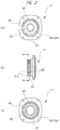
- a plurality of recessed portions 42 are provided along the circumferential direction thereof at a constant interval. Specifically, as shown in FIGS. 2 (a) and (c) , the eight recessed portions 42 are formed across about half around the outer circumferential surface of the attachment base 41.
- a relief portion 43 is formed on the outer circumferential surface of the attachment base 41 and in the region in which the recessed portions 42 are not formed. The relief portion 43 is dented toward the inner side of the attachment base 41, and a bottom surface of the relief portion 43 is flat. Note that, as shown in FIGS.
- the eight recessed portions 42 include a recessed portion 42a which is opposed to the relief portion 43 with the center of the through hole 40 interposed therebetween.
- the relief portion 43 and the recessed portion 42a are disposed at the positions, which are different by 180 degrees from each other, and are opposed to each other.
- engaging portions 41a which are projecting outward from the outer circumferential surface of the attachment base 41 and engaged with projecting portions 35 ( FIG. 3 ) of a later-described mating portion 32, are provided. Therefore, the engaging portions 41a are provided on the attachment base 41 and in the region excluding the regions in which the recessed portions 42 are provided.
- the wheel guard 30 has a cover portion including a horizontal part 30a, which is extending in the radial direction of the spindle 20, and a perpendicular part 30b, which is extending in the axial direction of the spindle 20 from a rim of the horizontal part 30a, and the wheel guard 30 has an approximately fan shape when seen in a plan view ( FIG. 3 (a) ).
- the horizontal part 30a of the wheel guard 30 is parallel to the rotation plane of the grinding wheel 2.
- the perpendicular part 30b of the wheel guard 30 is at a right angle with respect to the rotation plane of the grinding wheel 2 and covers the radial-direction outer side of the grinding wheel 2.
- an approximately circular opening 31 is formed in the horizontal part 30a of the wheel guard 30.
- the tubular mating portion 32 extending from the rim of the opening 31 to the upper side along the axis of the opening 31 is integrally formed on the upper surface of the horizontal part 30a. Note that the horizontal part 30a and the mating portion 32 which are separated from each other may be integrated by, for example, welding.
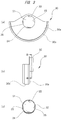
- a protruding portion 33 is provided on an inner circumferential surface of the mating portion 32.
- a plate spring 34 serving as an elastic body is provided on the inner circumferential surface of the mating portion 32 and at the position opposed to the protruding portion 33. Therefore, the protruding portion 33 and the plate spring 34 are disposed at the positions, which are different from each other by 180 degrees, and are opposed to each other. In other words, the protruding portion 33 and the plate spring 34 are disposed at symmetrical positions with respect to the spindle 20 shown in FIG. 1 .
- the plate spring 34 is curved toward the inner side of the mating portion 32.
- the center of the plate spring 34 is projecting toward the center of the mating portion 32.
- the plate spring 34 is curved so that the longitudinal-direction center thereof is the closest to the protruding portion 33.
- the pair of projecting portions 35 which are projecting inward from the inner circumferential surface, are provided. The projecting amount of the projecting portion 35 toward the radial-direction inner side of the mating portion 32 is smaller than the projecting amount of the protruding portion 33.
- the wheel guard 30 can be prevented from falling from the attachment base 41.
- the plate spring 34 and the protruding portion 33 are also engaged with the engaging portions 41a in the top-bottom direction, and the wheel guard 30 can be more reliably prevented from falling from the attachment base 41.
- the wheel guard 30 is attached to the packing gland 11 from the lower side of the packing gland 11.
- the attachment base 41 which is extending from the lower surface of the packing gland 11 to the lower side, is mated with the inner side of the mating portion 32, which is extending from the upper surface of the wheel guard 30 to the upper side.
- the plate spring 34 provided on the inner circumferential surface of the mating portion 32 is disposed between the inner circumferential surface of the mating portion 32 and the outer circumferential surface of the attachment base 41. More specifically, the plate spring 34 is disposed between the inner circumferential surface of the mating portion 32 and the bottom surface of the relief portion 43.
- the protruding portion 33 at the position different by 180 degrees with respect to the plate spring 34 is attracted to the opposed recessed portion 42 and is mated with the recessed portion 42. Therefore, the attachment base 41 (recessed portion 42) and the mating portion 32 (protruding portion 33) are mated with each other by the bias of the plate spring 34, and the wheel guard 30 is fixed.
- the position of the wheel guard 30 shown in FIG. 5 (a) is changed in a below manner.
- the wheel guard 30 is pushed (or pulled) to displace the wheel guard 30 in the radial direction (arrow direction) of the through hole 40 against the bias of the plate spring 34.
- the plate spring 34 is bent to displace (move) the wheel guard 30 from the perpendicular-part side to the mating-portion side shown in FIG. 3 (b) .
- the protruding portion 33 is detached from the recessed portion 42. Therefore, the mating between the attachment base 41 (recessed portion 42) and the mating portion 32 (protruding portion 33) is cancelled, and fixation of the wheel guard 30 is cancelled.
- the wheel guard 30 is turned by a desired angle to an arrow direction shown in FIG. 5 (b) .
- the wheel guard 30 is turned by the amount corresponding to a single recessed portion.
- a clearance required for ensuring the moving distance exceeding the mating length is provided between the inner circumferential surface of the mating portion 32 and the outer circumferential surface of the attachment base 41.
- a cross-sectional shape of the mating portion 32 is an approximately elliptical shape, thereby ensuring the above described clearance.
- the protruding portion 33 is disposed in the opposite side of the perpendicular part 30b with the center of the mating portion 32 interposed therebetween. Therefore, the force applied to the wheel guard 30 when the broken pieces of the grinding wheel 2 collide with the inner surface of the perpendicular part does not detach the protruding portion 33 from the recessed portion 42 ( FIG. 2 ). In other words, the force applied to the wheel guard 30 when the broken pieces of the grinding wheel 2 collide with the inner surface of the perpendicular part may act to reinforce the mating between the recessed portion 42 and the protruding portion 33, but does not act to cancel the mating between the recessed portion 42 and the protruding portion 33.
- the plate spring 34 serving as the elastic body can be replaced by a coiled spring, rubber, or the like.
- the protruding portion 33 is only required to be provided on either one of the attachment base 41 and the mating portion 32, and the recessed portion 42 is only required to be provided on the other one of the attachment base 41 and the mating portion 32. Therefore, the protruding portion 33 can be provided on the attachment base 41, and the recessed portion 42 can be provided on the mating portion 32.
- the protruding portion 33 is only required to be provided on either one of the wheel guard 30 and the attachment base 41, and the recessed portion 42 is only required to be provided on the other one of the wheel guard 30 and the attachment base 41. Furthermore, the number and disposition of the recessed portion 42 and the protruding portion 33 can be appropriately changed as necessary.
Landscapes
- Engineering & Computer Science (AREA)
- Mechanical Engineering (AREA)
- Grinding-Machine Dressing And Accessory Apparatuses (AREA)
- Finish Polishing, Edge Sharpening, And Grinding By Specific Grinding Devices (AREA)
Abstract
Description
- The present invention relates to a grinder to which a rotating tool is attached.
- A grinder is provided with a spindle, which is subjected to a rotary drive, and various rotating tools are attached to the spindle depending on purposes and uses. For example, a disk-shaped grinding stone, a brush, a cutter, etc. are attached to the spindle of the grinder. The grinding stone to be attached to the spindle of the grinder includes a grinding stone for polishing and a grinding stone for cutting. The brush to be attached to the spindle of the grinder includes a wire brush and a wireless brush. The cutter to be attached to the spindle of the grinder includes a diamond cutter. In the below explanations, various rotating tools attached to the spindle may be collectively referred to as "wheel".
- The grinder as described above is required to attach a wheel guard that covers 1/2 or more the outer circumference of the wheel. Moreover, when the grinder is used, the attachment position of the wheel guard has to be changed depending on purposes and uses.
- Therefore,
Patent Document 1 describes a grinder in which the attachment position of the wheel guard can be changed without using a tool such as a wrench or a screwdriver. In the grinder described inPatent Document 1, the wheel guard is turnably attached to a packing gland. The packing gland is provided with a retaining groove, and a set ring of the wheel guard is provided with a rib, which is mated with the retaining groove. Furthermore, between the packing gland and the set ring, a coiled spring, which prevents the rib mated with the retaining groove from falling, is disposed. - In the grinder described in
Patent Document 1 provided with the above described structure, when the wheel guard is pushed up to the axial-direction upper side of the spindle against bias of the coiled spring, the mating between the retaining groove and the rib is cancelled. Therefore, fixation of the wheel guard is cancelled, and the attachment position of the wheel guard can be changed. Then, when push-up with respect to the wheel guard is cancelled, the rib is mated with the retaining groove again by the bias of the coiled spring. Therefore, the wheel guard is fixed at a new attachment position. - Patent Document 1: Japanese Utility Model Application Publication Laid-Open No.
H6(1994)-36764 - In the grinder described in
Patent Document 1, when the wheel guard is pushed up to the axial-direction upper side of the spindle, the fixation of the wheel guard is cancelled. Herein, in many cases, the wheel attached to the grinder is retained approximately parallel to the surface of an object such as stone, concrete and wood and is pushed against the object surface. At this point, if the wheel guard contacts the object surface for some reason, the force which is upward in the axial direction of the spindle is applied to the wheel guard. In other words, the force that acts to cancel the fixation of the wheel guard is applied to the wheel guard. Therefore, the fixation of the wheel guard may be cancelled against the intention of the operator who is using the grinder. - An object of the present invention is to reduce, as much as possible, the possibility that the fixation of the wheel guard is cancelled against the intention of the operator.
- A grinder of the present invention is provided with a spindle to which a rotating tool is attached and a wheel guard covering the rotating tool attached to the spindle, and the grinder includes: an attachment base provided on a main body rotatably retaining the spindle, the attachment base surrounding the spindle; a mating portion provided on the wheel guard and mated with the attachment base; a recessed portion provided on either one of the attachment base and the mating portion; and a protruding portion provided on the other one of the attachment base and the mating portion. Then, when the wheel guard is displaced in a radial direction of the spindle, mating between the recessed portion and the protruding portion is cancelled, and the wheel guard is turnable in a circumferential direction of the spindle.
- In an aspect of the present invention, the grinder is provided with an elastic body disposed between the attachment base and the mating portion, and when the wheel guard is displaced in a radial direction of the spindle against bias of the elastic body, the mating between the recessed portion and the protruding portion is cancelled, and the wheel guard is turnable in the circumferential direction of the spindle.
- In another aspect of the present invention, the recessed portion is provided on an outer circumferential surface of the attachment base, the protruding portion is provided on an inner circumferential surface of the mating portion, and the elastic body is provided on the inner circumferential surface of the mating portion and at a position opposed to the protruding portion.
- In another aspect of the present invention, the elastic body is a plate spring curved toward an inner side of the mating portion.
- In another aspect of the present invention, the main body includes: a housing housing a drive source of the spindle; and a gear case rotatably retaining the spindle. The attachment base is integrally formed with a cover member covering an opening of the gear case.
- In another aspect of the present invention, the grinder is provided with a projecting portion projecting inward from the inner circumferential surface of the mating portion, and an engaging portion projecting outward from the outer circumferential surface of the attachment base and engaged with the projecting portion.
- In another aspect of the present invention, the recessed portion is provided on the attachment base, and the engaging portion is provided in a region of the attachment base excluding a region in which the recessed portion is provided.
- In another aspect of the present invention, a grinder is provided with an output shaft to which a rotating tool is attached, a wheel guard covering the rotating tool, and an attachment base to which the wheel guard is attached, and the grinder includes: a recessed portion provided on either one of the wheel guard and the attachment base; and a protruding portion provided on the other one of the wheel guard and the attachment base. Then, the recessed portion and the protruding portion are mated with each other in a radial direction of the output shaft.
- In another aspect of the present invention, the grinder is provided with an elastic body disposed between the wheel guard and the attachment base in the radial direction of the output shaft, and biasing either one of the protruding portion and the recessed portion toward the other one of the protruding portion and the recessed portion.
- In another aspect of the present invention, the wheel guard is provided with either one of the protruding portion and the recessed portion, the elastic body, and a perpendicular part covering a radial-direction outer side of the rotating tool. The perpendicular part is provided in a side in which the elastic body is provided in relation with the output shaft.
- In another aspect of the present invention, either one of the protruding portion and the recessed portion, and the elastic body are provided at symmetrical positions with respect to the output shaft.
- In another aspect of the present invention, a grinder includes: an output shaft to which a rotating tool is attached; a wheel guard provided with a mating portion and a perpendicular part covering the rotating tool; and an attachment base to which the mating portion is attached. The wheel guard is movable from the mating-portion side to the perpendicular-part side, and the mating portion and the attachment base are mated with each other in a moving direction of the wheel guard.
- In another aspect of the present invention, the grinder is provided with a recessed portion provided on either one of the mating portion and the attachment base, and a protruding portion provided on the other one of the mating portion and the attachment base. The recessed portion and the protruding portion are disposed in an opposite side of the perpendicular part with respect to the output shaft.
- In another aspect of the present invention, the grinder is provided with an elastic body biasing the wheel guard to the perpendicular-part side.
- In another aspect of the present invention, the grinder is provided with an elastic body causing the recessed portion and the protruding portion to be mated with each other in a radial direction of the output shaft.
- According to the present invention, the possibility that the fixation of the wheel guard is cancelled against the intention of the operator is reduced.
-
-
FIG. 1 a cross-sectional view showing a structure of a grinder to which the present invention is applied; -
FIG. 2 (a) is a bottom view of a packing gland, (b) is a lateral view, and (c) is a cross-sectional view taken along a line A-A shown in (b); -
FIG. 3 (a) is a bottom view of a wheel guard, (b) is a lateral view, and (c) is a cross-sectional view taken along a line B-B shown in (b); -
FIG. 4 (a) is a lateral view showing an attachment procedure of the wheel guard, and (b) is a cross-sectional view showing a mating state of an attachment base and a mating portion; and -
FIGS. 5 (a) to (d) are explanatory views showing a procedure of changing the attachment position of the wheel guard. - Hereinafter, an example of a grinder to which the present invention is applied will be explained in detail with reference to the drawings. As shown in
FIG. 1 , agrinder 1 according to the present embodiment is provided with a diamond grinding wheel (hereinafter, referred to as "grindingwheel 2".) serving as a rotating tool and is used in, for example, a grinding operation of planarizing the surfaces of concrete, stone, etc. - The
grinder 1 is provided with a main body 5 including ahousing 3 and a gear case 4. Thehousing 3 has an approximately cylindrical shape as a whole, and anelectric motor 6 serving as a drive source is housed in thehousing 3. Theelectric motor 6 is connected to a commercial electric-power source via an electric-power-source cord 7, which is extended from a rear end of thehousing 3. - The gear case 4 has a case
main body 10 and apacking gland 11 serving as a cover member, which covers an opening of the casemain body 10, and is attached to a distal end of thehousing 3. Two bearings (aneedle bearing 12 and a ball bearing 13) are provided in the gear case 4, and a spindle (output shaft) 20 is rotatably retained by these bearings. Thespindle 20 is orthogonal to anoutput shaft 6a of theelectric motor 6, and one end thereof is penetrating through the packinggland 11 and projecting to the outside. On the other hand, abevel gear 22, which is meshed with abevel gear 21 attached to theoutput shaft 6a of theelectric motor 6, is attached to the other end of thespindle 20 positioned in the gear case 4. The rotation direction of theelectric motor 6 is converted by 90 degrees by the above-described pair of bevel gears and is transmitted to thespindle 20 with a reduced rotation speed. In other words, thespindle 20 is subjected to rotary drive by theelectric motor 6. - The
grinding wheel 2 is provided with asubstrate 2a including a disk-shaped steel plate, and a plurality of diamond grinding stones are fixed to a surface of thesubstrate 2a by adhesion or another means. Moreover, an attachment hole into which thespindle 20 is inserted is provided at the center of thesubstrate 2a, and thegrinding wheel 2 is attached to thespindle 20, which penetrates through the attachment hole. Specifically, thegrinding wheel 2 is fixed to thespindle 20 by a wheel washer (s) and a lock nut(s), and rotated integrally with thespindle 20. Thehousing 3 is provided with an unshown switch. When this switch is operated, electric power is supplied to theelectric motor 6, and theoutput shaft 6a of theelectric motor 6 is rotated. As a result, thespindle 20 coupled to theoutput shaft 6a via the above-described pair of bevel gears is rotated, and thegrinding wheel 2 fixed to thespindle 20 is rotated. - A
wheel guard 30 covering at least 1/2 or more the outer circumference of thegrinding wheel 2 is attached to the gear case 4. Hereinafter, an attachment structure of thewheel guard 30 will be explained in detail. - As shown in
FIGS. 2 (a) and (c) , at the center of thepacking gland 11, a throughhole 40 through which the spindle 20 (FIG. 1 ) penetrates is provided. As shown inFIGS. 2 (a) to (c) , atubular attachment base 41 is integrally formed with a lower surface of thepacking gland 11. Theattachment base 41 is formed around the throughhole 40 so as to surround the throughhole 40. Moreover, theattachment base 41 is extending to the lower side along an axis of the throughhole 40. In other words, theattachment base 41 is annularly formed, and the axis of theattachment base 41 and the axis of the throughhole 40 are identical. Thus, theattachment base 41 surrounds the spindle 20 (FIG. 1 ) projecting from the throughhole 40. - On an outer circumferential surface of the
attachment base 41, a plurality of recessedportions 42 are provided along the circumferential direction thereof at a constant interval. Specifically, as shown inFIGS. 2 (a) and (c) , the eight recessedportions 42 are formed across about half around the outer circumferential surface of theattachment base 41. On the other hand, arelief portion 43 is formed on the outer circumferential surface of theattachment base 41 and in the region in which the recessedportions 42 are not formed. Therelief portion 43 is dented toward the inner side of theattachment base 41, and a bottom surface of therelief portion 43 is flat. Note that, as shown inFIGS. 2 (a) and(c) , the eight recessedportions 42 include a recessedportion 42a which is opposed to therelief portion 43 with the center of the throughhole 40 interposed therebetween. In other words, therelief portion 43 and the recessedportion 42a are disposed at the positions, which are different by 180 degrees from each other, and are opposed to each other. Furthermore, as shown inFIG. 2 (b) , at an end (grinding wheel side) of theattachment base 41 and in a region in which the recessedportions 42 are not provided, engagingportions 41a, which are projecting outward from the outer circumferential surface of theattachment base 41 and engaged with projecting portions 35 (FIG. 3 ) of a later-describedmating portion 32, are provided. Therefore, the engagingportions 41a are provided on theattachment base 41 and in the region excluding the regions in which the recessedportions 42 are provided. - As shown in
FIG. 1 , thewheel guard 30 has a cover portion including ahorizontal part 30a, which is extending in the radial direction of thespindle 20, and aperpendicular part 30b, which is extending in the axial direction of thespindle 20 from a rim of thehorizontal part 30a, and thewheel guard 30 has an approximately fan shape when seen in a plan view (FIG. 3 (a) ). In other words, thehorizontal part 30a of thewheel guard 30 is parallel to the rotation plane of thegrinding wheel 2. On the other hand, theperpendicular part 30b of thewheel guard 30 is at a right angle with respect to the rotation plane of thegrinding wheel 2 and covers the radial-direction outer side of thegrinding wheel 2. - As shown in
FIG. 3 (a) , an approximatelycircular opening 31 is formed in thehorizontal part 30a of thewheel guard 30. Moreover, as shown inFIG. 3 (b) , thetubular mating portion 32 extending from the rim of theopening 31 to the upper side along the axis of theopening 31 is integrally formed on the upper surface of thehorizontal part 30a. Note that thehorizontal part 30a and themating portion 32 which are separated from each other may be integrated by, for example, welding. - As shown in
FIGS. 3 (a) and (c) , a protrudingportion 33 is provided on an inner circumferential surface of themating portion 32. Moreover, aplate spring 34 serving as an elastic body is provided on the inner circumferential surface of themating portion 32 and at the position opposed to the protrudingportion 33. Therefore, the protrudingportion 33 and theplate spring 34 are disposed at the positions, which are different from each other by 180 degrees, and are opposed to each other. In other words, the protrudingportion 33 and theplate spring 34 are disposed at symmetrical positions with respect to thespindle 20 shown inFIG. 1 . Theplate spring 34 is curved toward the inner side of themating portion 32. Specifically, while both ends of theplate spring 34 are fixed to the inner circumferential surface of themating portion 32, the center of theplate spring 34 is projecting toward the center of themating portion 32. In other words, theplate spring 34 is curved so that the longitudinal-direction center thereof is the closest to the protrudingportion 33. Furthermore, on the inner circumferential surface of themating portion 32, the pair of projectingportions 35, which are projecting inward from the inner circumferential surface, are provided. The projecting amount of the projectingportion 35 toward the radial-direction inner side of themating portion 32 is smaller than the projecting amount of the protrudingportion 33. When the projectingportions 35 and the engagingportions 41a (FIG. 2 (b) ) of theattachment base 41 are engaged with each other in the top-bottom direction, thewheel guard 30 can be prevented from falling from theattachment base 41. Moreover, theplate spring 34 and the protrudingportion 33 are also engaged with the engagingportions 41a in the top-bottom direction, and thewheel guard 30 can be more reliably prevented from falling from theattachment base 41. - As shown in
FIG. 4 (a) , thewheel guard 30 is attached to thepacking gland 11 from the lower side of thepacking gland 11. In other words, theattachment base 41, which is extending from the lower surface of thepacking gland 11 to the lower side, is mated with the inner side of themating portion 32, which is extending from the upper surface of thewheel guard 30 to the upper side. - As shown in
FIG. 4 (b) , when theattachment base 41 is to be mated with themating portion 32, the position of therelief portion 43 provided on theattachment base 41 and the position of theplate spring 34 provided on themating portion 32 are aligned. When therelief portion 43 and theplate spring 34 are aligned, the position of the recessedportion 42a opposed to therelief portion 43 and the position of the protrudingportion 33 opposed to theplate spring 34 automatically match. Note that it is obvious that, when the recessedportion 42a and the protrudingportion 33 are aligned, the position of therelief portion 43 and the position of theplate spring 34 automatically match. In either case, when theattachment base 41 is mated with themating portion 32, as shown inFIG. 4 (b) , theplate spring 34 provided on the inner circumferential surface of themating portion 32 is disposed between the inner circumferential surface of themating portion 32 and the outer circumferential surface of theattachment base 41. More specifically, theplate spring 34 is disposed between the inner circumferential surface of themating portion 32 and the bottom surface of therelief portion 43. - Then, when the mating portion 32 (wheel guard 30) shown in
FIG. 4 (b) is turned counterclockwise, as shown inFIG. 5 (a) , theplate spring 34 is pushed into the gap between the inner circumferential surface of themating portion 32 and the outer circumferential surface of theattachment base 41 from the gap between the inner circumferential surface of themating portion 32 and the bottom surface of therelief portion 43, and is bent. Then, by the elastic restoring force of thebent plate spring 34, thewheel guard 30 is displaced (moved) from the mating-portion side to the perpendicular-part side shown inFIG. 3 (b) . As a result, as shown inFIG. 5 (a) , the protrudingportion 33 at the position different by 180 degrees with respect to theplate spring 34 is attracted to the opposed recessedportion 42 and is mated with the recessedportion 42. Therefore, the attachment base 41 (recessed portion 42) and the mating portion 32 (protruding portion 33) are mated with each other by the bias of theplate spring 34, and thewheel guard 30 is fixed. - The position of the
wheel guard 30 shown inFIG. 5 (a) is changed in a below manner. First, thewheel guard 30 is pushed (or pulled) to displace thewheel guard 30 in the radial direction (arrow direction) of the throughhole 40 against the bias of theplate spring 34. In other words, theplate spring 34 is bent to displace (move) thewheel guard 30 from the perpendicular-part side to the mating-portion side shown inFIG. 3 (b) . As a result, as shown inFIG. 5 (b) , the protrudingportion 33 is detached from the recessedportion 42. Therefore, the mating between the attachment base 41 (recessed portion 42) and the mating portion 32 (protruding portion 33) is cancelled, and fixation of thewheel guard 30 is cancelled. Note that it is obvious from the previous explanations and figures that the radial direction of the throughhole 40 shown inFIG. 5 (a) and the radial direction of thespindle 20 shown inFIG. 1 are the same direction. Therefore, when thewheel guard 30 is displaced in the radial direction of thespindle 20 against the bias of theplate spring 34, the mating between the recessedportion 42 and the protrudingportion 33 is cancelled, and the fixation of thewheel guard 30 is cancelled. Therefore, thewheel guard 30 is turnable in a circumferential direction of thespindle 20. - Then, while pushing (or pulling) with respect to the
wheel guard 30 is maintained, thewheel guard 30 is turned by a desired angle to an arrow direction shown inFIG. 5 (b) . For example, as shown inFIG. 5 (b) and (c) , thewheel guard 30 is turned by the amount corresponding to a single recessed portion. - Then, when pushing (or pulling) with respect to the
wheel guard 30 is cancelled, as shown inFIG. 5 (d) , the protrudingportion 33 is mated with the new recessedportion 42 by the bias of theplate spring 34, and thewheel guard 30 is fixed again. Note that, in order to displace thewheel guard 30 in the above described manner, a clearance is required between the inner circumferential surface of themating portion 32 and the outer circumferential surface of theattachment base 41. Specifically, when thewheel guard 30 is displaced in the radial direction of thespindle 20, the protrudingportion 33 is also displaced (moved) to the same direction by the same distance. Then, in order to detach the protrudingportion 33, which is mated with the recessedportion 42, from the recessedportion 42, the moving distance of the protrudingportion 33 has to exceed the mating length. Therefore, a clearance required for ensuring the moving distance exceeding the mating length is provided between the inner circumferential surface of themating portion 32 and the outer circumferential surface of theattachment base 41. In the present embodiment, a cross-sectional shape of themating portion 32 is an approximately elliptical shape, thereby ensuring the above described clearance. - In the present embodiment, when the
wheel guard 30 shown inFIG. 1 is displaced in the radial direction of thespindle 20, the mating between the recessed portion 42 (FIG. 2 ) provided on thepacking gland 11 and the protruding portion 33 (FIG. 3 ) provided on thewheel guard 30 is cancelled, and the fixation of thewheel guard 30 is cancelled. In other words, even if upward force in the axial direction of thespindle 20 or downward force in the axial direction thereof is applied to thewheel guard 30, the mating between the recessedportion 42 and the protrudingportion 33 is not cancelled, and the fixation of thewheel guard 30 is also not cancelled. Therefore, the possibility that the fixation of thewheel guard 30 is cancelled against the intention of an operator who is using thegrinder 1 is extremely low. Furthermore, when thegrinding wheel 2 shown inFIG. 1 is broken during rotation, in many cases, broken pieces of thegrinding wheel 2 collide with the inner surface of theperpendicular part 30b of thewheel guard 30. At that point, outward force in the radial direction of thespindle 20 is applied to thewheel guard 30. In other words, the force that acts so as to cancel the fixation of thewheel guard 30 is applied to thewheel guard 30. - However, as shown in
FIGS. 3 (a) and (c) , the protrudingportion 33 is disposed in the opposite side of theperpendicular part 30b with the center of themating portion 32 interposed therebetween. Therefore, the force applied to thewheel guard 30 when the broken pieces of thegrinding wheel 2 collide with the inner surface of the perpendicular part does not detach the protrudingportion 33 from the recessed portion 42 (FIG. 2 ). In other words, the force applied to thewheel guard 30 when the broken pieces of thegrinding wheel 2 collide with the inner surface of the perpendicular part may act to reinforce the mating between the recessedportion 42 and the protrudingportion 33, but does not act to cancel the mating between the recessedportion 42 and the protrudingportion 33. Furthermore, in order to cancel the fixation of thewheel guard 30, only thewheel guard 30 is required to be operated. Therefore, compared with the case in which a cancellation button for cancelling the fixation of thewheel guard 30 is provided, the number of parts is reduced. Moreover, the fixation of thewheel guard 30 can be easily cancelled even with a work glove (s) on, and as a result the operability is good. Furthermore, the possibility that the fixation of thewheel guard 30 is cancelled when an operation is carried out by pushing the main body 5 against thegrinding wheel 2 side is extremely low. - The present invention is not limited to the above described embodiment, and various modifications can be made without departing from the gist thereof. For example, the
plate spring 34 serving as the elastic body can be replaced by a coiled spring, rubber, or the like. Moreover, the protrudingportion 33 is only required to be provided on either one of theattachment base 41 and themating portion 32, and the recessedportion 42 is only required to be provided on the other one of theattachment base 41 and themating portion 32. Therefore, the protrudingportion 33 can be provided on theattachment base 41, and the recessedportion 42 can be provided on themating portion 32. Moreover, the protrudingportion 33 is only required to be provided on either one of thewheel guard 30 and theattachment base 41, and the recessedportion 42 is only required to be provided on the other one of thewheel guard 30 and theattachment base 41. Furthermore, the number and disposition of the recessedportion 42 and the protrudingportion 33 can be appropriately changed as necessary. -
- 1
- GRINDER
- 2
- GRINDING WHEEL
- 2a
- SUBSTRATE
- 3
- HOUSING
- 4
- GEAR CASE
- 5
- MAIN BODY
- 6
- ELECTRIC MOTOR
- 6a
- OUTPUT SHAFT
- 7
- ELECTRIC-POWER-SOURCE CORD
- 10
- CASE MAIN BODY
- 11
- PACKING GLAND
- 12
- NEEDLE BEARING
- 13
- BALL BEARING
- 20
- SPINDLE
- 21
- BEVEL GEAR
- 22
- BEVEL GEAR
- 30
- WHEEL GUARD
- 30a
- HORIZONTAL PART
- 30b
- PERPENDICULAR PART
- 31
- OPENING
- 32
- MATING PORTION
- 33
- PROTRUDING PORTION
- 34
- PLATE SPRING
- 35
- PROJECTING PORTION
- 40
- THROUGH HOLE
- 41
- ATTACHMENT BASE
- 41a
- ENGAGING PORTION
- 42, 42a
- RECESSED PORTION
- 43
- RELIEF PORTION
Claims (15)
- A grinder provided with a spindle to which a rotating tool is attached and a wheel guard covering the rotating tool attached to the spindle, the grinder comprising:an attachment base provided on a main body rotatably retaining the spindle, the attachment base surrounding the spindle;a mating portion provided on the wheel guard and mated with the attachment base;a recessed portion provided on either one of the attachment base and the mating portion; anda protruding portion provided on the other one of the attachment base and the mating portion,wherein when the wheel guard is displaced in a radial direction of the spindle, mating between the recessed portion and the protruding portion is cancelled, andthe wheel guard is turnable in a circumferential direction of the spindle.
- The grinder according to claim 1, comprising an elastic body disposed between the attachment base and the mating portion,
wherein when the wheel guard is displaced in a radial direction of the spindle against bias of the elastic body, the mating between the recessed portion and the protruding portion is cancelled, and
the wheel guard is turnable in the circumferential direction of the spindle. - The grinder according to claim 2,
wherein the recessed portion is provided on an outer circumferential surface of the attachment base,
the protruding portion is provided on an inner circumferential surface of the mating portion, and
the elastic body is provided on the inner circumferential surface of the mating portion and at a position opposed to the protruding portion. - The grinder according to claim 3,
wherein the elastic body is a plate spring curved toward an inner side of the mating portion. - The grinder according to any of claims 1 to 4,
wherein the main body includes:a housing housing a drive source of the spindle; anda gear case rotatably retaining the spindle, andthe attachment base is integrally formed with a cover member covering an opening of the gear case. - The grinder according to any of claims 1 to 5, comprising:a projecting portion projecting inward from the inner circumferential surface of the mating portion; andan engaging portion projecting outward from the outer circumferential surface of the attachment base and engaged with the projecting portion.
- The grinder according to claim 6,
wherein the recessed portion is provided on the attachment base, and
the engaging portion is provided in a region of the attachment base excluding a region in which the recessed portion is provided. - A grinder provided with an output shaft to which a rotating tool is attached, a wheel guard covering the rotating tool, and an attachment base to which the wheel guard is attached, the grinder comprising:a recessed portion provided on either one of the wheel guard and the attachment base; anda protruding portion provided on the other one of the wheel guard and the attachment base,wherein the recessed portion and the protruding portion are mated with each other in a radial direction of the output shaft.
- The grinder according to claim 8, comprising an elastic body disposed between the wheel guard and the attachment base in the radial direction of the output shaft, and biasing either one of the protruding portion and the recessed portion toward the other one of the protruding portion and the recessed portion.
- The grinder according to claim 9,
wherein the wheel guard is provided with either one of the protruding portion and the recessed portion, the elastic body, and a perpendicular part covering a radial-direction outer side of the rotating tool, and
the perpendicular part is provided in a side in which the elastic body is provided in relation with the output shaft. - The grinder according to claim 10,
wherein either one of the protruding portion and the recessed portion, and the elastic body are provided at symmetrical positions with respect to the output shaft. - A grinder comprising:an output shaft to which a rotating tool is attached;a wheel guard provided with a mating portion and a perpendicular part covering the rotating tool; andan attachment base to which the mating portion is attached,wherein the wheel guard is movable from the mating-portion side to the perpendicular-part side, andthe mating portion and the attachment base are mated with each other in a moving direction of the wheel guard.
- The grinder according to claim 12, comprising:a recessed portion provided on either one of the mating portion and the attachment base; anda protruding portion provided on the other one of the mating portion and the attachment base,wherein the recessed portion and the protruding portion are disposed in an opposite side of the perpendicular part with respect to the output shaft.
- The grinder according to claim 13, comprising an elastic body biasing the wheel guard to the perpendicular-part side.
- The grinder according to claim 13, comprising an elastic body causing the recessed portion and the protruding portion to be mated with each other in a radial direction of the output shaft.
Applications Claiming Priority (2)
| Application Number | Priority Date | Filing Date | Title |
|---|---|---|---|
| JP2013176031 | 2013-08-27 | ||
| PCT/JP2014/069709 WO2015029659A1 (en) | 2013-08-27 | 2014-07-25 | Grinder |
Publications (2)
| Publication Number | Publication Date |
|---|---|
| EP3040159A1 true EP3040159A1 (en) | 2016-07-06 |
| EP3040159A4 EP3040159A4 (en) | 2017-07-19 |
Family
ID=52586233
Family Applications (1)
| Application Number | Title | Priority Date | Filing Date |
|---|---|---|---|
| EP14839714.4A Withdrawn EP3040159A4 (en) | 2013-08-27 | 2014-07-25 | Grinder |
Country Status (5)
| Country | Link |
|---|---|
| US (1) | US20160193713A1 (en) |
| EP (1) | EP3040159A4 (en) |
| JP (1) | JP6044718B2 (en) |
| CN (1) | CN105473281A (en) |
| WO (1) | WO2015029659A1 (en) |
Families Citing this family (7)
| Publication number | Priority date | Publication date | Assignee | Title |
|---|---|---|---|---|
| US9387578B2 (en) * | 2013-10-28 | 2016-07-12 | Black & Decker Inc. | Handle arrangement for sander |
| USD785339S1 (en) * | 2014-10-23 | 2017-05-02 | Griot's Garage, Inc. | Hand applicator buffing pad |
| JP1571886S (en) * | 2016-09-20 | 2018-03-05 | ||
| CN108500839B (en) * | 2018-03-02 | 2020-05-22 | 陈中友 | A polisher for building decoration |
| JP2019155486A (en) * | 2018-03-07 | 2019-09-19 | 株式会社マキタ | Electric tool |
| JP7110025B2 (en) * | 2018-08-07 | 2022-08-01 | 株式会社マキタ | Electric tool |
| KR102730071B1 (en) * | 2022-06-27 | 2024-11-13 | 김미숙 | Coupler for clamping polishing disk |
Family Cites Families (14)
| Publication number | Priority date | Publication date | Assignee | Title |
|---|---|---|---|---|
| JPS61127966U (en) * | 1985-01-25 | 1986-08-11 | ||
| DE3636601A1 (en) * | 1986-10-28 | 1988-05-05 | Bosch Gmbh Robert | PROTECTIVE COVER FOR GRINDING MACHINES, ESPECIALLY ANGLE GRINDERS, AND THE FASTENING MOUNTING THAT MATCH THEM |
| DE3913898A1 (en) * | 1989-04-27 | 1990-10-31 | Licentia Gmbh | Adjustable guard for portable power tools - has indent mechanism for angular adjustment and finger pressure actuated fastening to spindle nose |
| JPH0636764U (en) | 1992-10-23 | 1994-05-17 | 日立工機株式会社 | Wheel grinder holding structure for disc grinder |
| US5637035A (en) * | 1995-06-28 | 1997-06-10 | Milwaukee Electric Tool Corporation | Adjustable guard arrangement for power tool |
| DE10259520A1 (en) * | 2002-12-19 | 2004-07-01 | Robert Bosch Gmbh | Electric hand tool |
| DE102007041840A1 (en) * | 2006-11-13 | 2008-05-15 | Robert Bosch Gmbh | Hand tool with protective hood, in particular angle grinder |
| DE102006053303A1 (en) * | 2006-11-13 | 2008-05-15 | Robert Bosch Gmbh | Hand tool for a rotating tool with protective cover |
| DE102007052684A1 (en) * | 2007-11-05 | 2009-05-07 | Robert Bosch Gmbh | Hand tool |
| DE102009048357A1 (en) * | 2009-10-06 | 2011-04-21 | Metabowerke Gmbh | Electric hand tool |
| JP5544867B2 (en) * | 2009-12-21 | 2014-07-09 | 日立工機株式会社 | Grinder |
| CN201711848U (en) * | 2010-02-09 | 2011-01-19 | 南京德朔实业有限公司 | Motive power tool |
| CN202162675U (en) * | 2011-06-27 | 2012-03-14 | 宁波国图电机有限公司 | Angle grinder |
| US9475172B2 (en) * | 2014-07-15 | 2016-10-25 | Milwaukee Electric Tool Corporation | Adjustable guard for power tool |
-
2014
- 2014-07-25 CN CN201480045741.XA patent/CN105473281A/en active Pending
- 2014-07-25 WO PCT/JP2014/069709 patent/WO2015029659A1/en not_active Ceased
- 2014-07-25 EP EP14839714.4A patent/EP3040159A4/en not_active Withdrawn
- 2014-07-25 US US14/912,237 patent/US20160193713A1/en not_active Abandoned
- 2014-07-25 JP JP2015534091A patent/JP6044718B2/en not_active Expired - Fee Related
Non-Patent Citations (1)
| Title |
|---|
| See references of WO2015029659A1 * |
Also Published As
| Publication number | Publication date |
|---|---|
| JPWO2015029659A1 (en) | 2017-03-02 |
| EP3040159A4 (en) | 2017-07-19 |
| WO2015029659A1 (en) | 2015-03-05 |
| JP6044718B2 (en) | 2016-12-14 |
| CN105473281A (en) | 2016-04-06 |
| US20160193713A1 (en) | 2016-07-07 |
Similar Documents
| Publication | Publication Date | Title |
|---|---|---|
| US20160193713A1 (en) | Grinder | |
| US8851960B2 (en) | Rotary tool | |
| US10525580B2 (en) | Power tool | |
| US9358664B2 (en) | Grinder | |
| JP6020767B2 (en) | Electric tool | |
| EP2420352B1 (en) | Hand-held tools | |
| JP2017052059A (en) | Grinder | |
| GB2461783A (en) | Rotationally adjustable power tool protective hood | |
| US20150367495A1 (en) | Power tool | |
| US10173298B2 (en) | Reversible lever for a guard assembly for a power tool | |
| US12390868B2 (en) | Electric working machine | |
| US11648657B2 (en) | Handheld power tool | |
| JP2016049574A (en) | Tip tool cover and electric tool | |
| JP6163967B2 (en) | Power tool and accessory tool fixing structure | |
| CN202114566U (en) | Power tool | |
| JP2017007001A (en) | Hand-held power tool | |
| JP2020203333A (en) | Power tool | |
| KR101692867B1 (en) | Fixing structure of grinder wheelguard | |
| US12275114B2 (en) | Belt sander | |
| KR101379952B1 (en) | Air grinder | |
| JP2019181618A (en) | Electric tool and dust collection cover | |
| JP3751616B2 (en) | Grinder | |
| US20240173821A1 (en) | Power tool | |
| KR100500311B1 (en) | Abrasion apparatus of cutter for electric shaver | |
| JP6662605B2 (en) | Brush cutter |
Legal Events
| Date | Code | Title | Description |
|---|---|---|---|
| PUAI | Public reference made under article 153(3) epc to a published international application that has entered the european phase |
Free format text: ORIGINAL CODE: 0009012 |
|
| 17P | Request for examination filed |
Effective date: 20160215 |
|
| AK | Designated contracting states |
Kind code of ref document: A1 Designated state(s): AL AT BE BG CH CY CZ DE DK EE ES FI FR GB GR HR HU IE IS IT LI LT LU LV MC MK MT NL NO PL PT RO RS SE SI SK SM TR |
|
| AX | Request for extension of the european patent |
Extension state: BA ME |
|
| DAX | Request for extension of the european patent (deleted) | ||
| A4 | Supplementary search report drawn up and despatched |
Effective date: 20170616 |
|
| RIC1 | Information provided on ipc code assigned before grant |
Ipc: B23Q 11/08 20060101ALI20170609BHEP Ipc: B24B 55/05 20060101ALI20170609BHEP Ipc: B24B 23/02 20060101AFI20170609BHEP |
|
| STAA | Information on the status of an ep patent application or granted ep patent |
Free format text: STATUS: REQUEST FOR EXAMINATION WAS MADE |
|
| STAA | Information on the status of an ep patent application or granted ep patent |
Free format text: STATUS: THE APPLICATION IS DEEMED TO BE WITHDRAWN |
|
| 18D | Application deemed to be withdrawn |
Effective date: 20180116 |