EP3040036B1 - Instrumentenkopf, Applikationsinstrument mit entsprechendem Instrumentenkopf und Applikationssystem - Google Patents
Instrumentenkopf, Applikationsinstrument mit entsprechendem Instrumentenkopf und Applikationssystem Download PDFInfo
- Publication number
- EP3040036B1 EP3040036B1 EP14200435.7A EP14200435A EP3040036B1 EP 3040036 B1 EP3040036 B1 EP 3040036B1 EP 14200435 A EP14200435 A EP 14200435A EP 3040036 B1 EP3040036 B1 EP 3040036B1
- Authority
- EP
- European Patent Office
- Prior art keywords
- fluid
- valve
- pressure
- instrument
- inflow line
- Prior art date
- Legal status (The legal status is an assumption and is not a legal conclusion. Google has not performed a legal analysis and makes no representation as to the accuracy of the status listed.)
- Active
Links
- 239000012530 fluid Substances 0.000 claims description 150
- 238000013022 venting Methods 0.000 claims description 12
- 229920001971 elastomer Polymers 0.000 claims description 3
- 239000000806 elastomer Substances 0.000 claims description 2
- 239000000126 substance Substances 0.000 description 34
- 210000001519 tissue Anatomy 0.000 description 29
- 238000009423 ventilation Methods 0.000 description 19
- 230000008901 benefit Effects 0.000 description 10
- 239000000725 suspension Substances 0.000 description 10
- 230000000694 effects Effects 0.000 description 9
- 230000006870 function Effects 0.000 description 8
- 238000007789 sealing Methods 0.000 description 8
- XLYOFNOQVPJJNP-UHFFFAOYSA-N water Substances O XLYOFNOQVPJJNP-UHFFFAOYSA-N 0.000 description 8
- 239000003380 propellant Substances 0.000 description 7
- 239000007788 liquid Substances 0.000 description 6
- 102100021469 Equilibrative nucleoside transporter 1 Human genes 0.000 description 5
- 102100021468 Equilibrative nucleoside transporter 2 Human genes 0.000 description 5
- 101000822020 Homo sapiens Equilibrative nucleoside transporter 1 Proteins 0.000 description 5
- 101000822017 Homo sapiens Equilibrative nucleoside transporter 2 Proteins 0.000 description 5
- 238000004891 communication Methods 0.000 description 5
- 238000010276 construction Methods 0.000 description 5
- 239000000463 material Substances 0.000 description 5
- 238000005273 aeration Methods 0.000 description 4
- 239000006285 cell suspension Substances 0.000 description 4
- 238000000034 method Methods 0.000 description 4
- 239000000523 sample Substances 0.000 description 4
- 210000004877 mucosa Anatomy 0.000 description 3
- 210000003205 muscle Anatomy 0.000 description 3
- 210000005070 sphincter Anatomy 0.000 description 3
- 230000008719 thickening Effects 0.000 description 3
- 210000001635 urinary tract Anatomy 0.000 description 3
- FAPWRFPIFSIZLT-UHFFFAOYSA-M Sodium chloride Chemical compound [Na+].[Cl-] FAPWRFPIFSIZLT-UHFFFAOYSA-M 0.000 description 2
- 230000002457 bidirectional effect Effects 0.000 description 2
- 238000013461 design Methods 0.000 description 2
- 239000003814 drug Substances 0.000 description 2
- 239000013013 elastic material Substances 0.000 description 2
- 210000004400 mucous membrane Anatomy 0.000 description 2
- 210000000056 organ Anatomy 0.000 description 2
- 238000005192 partition Methods 0.000 description 2
- 239000012783 reinforcing fiber Substances 0.000 description 2
- 230000000630 rising effect Effects 0.000 description 2
- 230000004083 survival effect Effects 0.000 description 2
- 229940124597 therapeutic agent Drugs 0.000 description 2
- 241001136792 Alle Species 0.000 description 1
- 230000001133 acceleration Effects 0.000 description 1
- 230000009471 action Effects 0.000 description 1
- 230000004913 activation Effects 0.000 description 1
- 238000005276 aerator Methods 0.000 description 1
- 230000002238 attenuated effect Effects 0.000 description 1
- 230000004888 barrier function Effects 0.000 description 1
- 230000006399 behavior Effects 0.000 description 1
- 210000000013 bile duct Anatomy 0.000 description 1
- 230000000740 bleeding effect Effects 0.000 description 1
- 230000000903 blocking effect Effects 0.000 description 1
- 230000008859 change Effects 0.000 description 1
- 239000000356 contaminant Substances 0.000 description 1
- 238000011217 control strategy Methods 0.000 description 1
- 230000007423 decrease Effects 0.000 description 1
- 230000007547 defect Effects 0.000 description 1
- 238000010790 dilution Methods 0.000 description 1
- 239000012895 dilution Substances 0.000 description 1
- 210000000981 epithelium Anatomy 0.000 description 1
- 230000002496 gastric effect Effects 0.000 description 1
- 238000002347 injection Methods 0.000 description 1
- 239000007924 injection Substances 0.000 description 1
- 230000010354 integration Effects 0.000 description 1
- 210000004379 membrane Anatomy 0.000 description 1
- 239000012528 membrane Substances 0.000 description 1
- 238000002156 mixing Methods 0.000 description 1
- 235000015097 nutrients Nutrition 0.000 description 1
- 239000002245 particle Substances 0.000 description 1
- 230000008569 process Effects 0.000 description 1
- 230000009467 reduction Effects 0.000 description 1
- 230000008929 regeneration Effects 0.000 description 1
- 238000011069 regeneration method Methods 0.000 description 1
- 230000002787 reinforcement Effects 0.000 description 1
- 238000000926 separation method Methods 0.000 description 1
- 239000011780 sodium chloride Substances 0.000 description 1
- 238000002560 therapeutic procedure Methods 0.000 description 1
- 238000012546 transfer Methods 0.000 description 1
- 230000007704 transition Effects 0.000 description 1
- 238000011144 upstream manufacturing Methods 0.000 description 1
Images


Classifications
-
- A—HUMAN NECESSITIES
- A61—MEDICAL OR VETERINARY SCIENCE; HYGIENE
- A61M—DEVICES FOR INTRODUCING MEDIA INTO, OR ONTO, THE BODY; DEVICES FOR TRANSDUCING BODY MEDIA OR FOR TAKING MEDIA FROM THE BODY; DEVICES FOR PRODUCING OR ENDING SLEEP OR STUPOR
- A61M5/00—Devices for bringing media into the body in a subcutaneous, intra-vascular or intramuscular way; Accessories therefor, e.g. filling or cleaning devices, arm-rests
- A61M5/178—Syringes
- A61M5/30—Syringes for injection by jet action, without needle, e.g. for use with replaceable ampoules or carpules
- A61M5/3007—Syringes for injection by jet action, without needle, e.g. for use with replaceable ampoules or carpules with specially designed jet passages at the injector's distal end
-
- A—HUMAN NECESSITIES
- A61—MEDICAL OR VETERINARY SCIENCE; HYGIENE
- A61B—DIAGNOSIS; SURGERY; IDENTIFICATION
- A61B1/00—Instruments for performing medical examinations of the interior of cavities or tubes of the body by visual or photographical inspection, e.g. endoscopes; Illuminating arrangements therefor
- A61B1/012—Instruments for performing medical examinations of the interior of cavities or tubes of the body by visual or photographical inspection, e.g. endoscopes; Illuminating arrangements therefor characterised by internal passages or accessories therefor
- A61B1/015—Control of fluid supply or evacuation
-
- A—HUMAN NECESSITIES
- A61—MEDICAL OR VETERINARY SCIENCE; HYGIENE
- A61B—DIAGNOSIS; SURGERY; IDENTIFICATION
- A61B17/00—Surgical instruments, devices or methods
- A61B17/32—Surgical cutting instruments
- A61B17/3203—Fluid jet cutting instruments
-
- A—HUMAN NECESSITIES
- A61—MEDICAL OR VETERINARY SCIENCE; HYGIENE
- A61M—DEVICES FOR INTRODUCING MEDIA INTO, OR ONTO, THE BODY; DEVICES FOR TRANSDUCING BODY MEDIA OR FOR TAKING MEDIA FROM THE BODY; DEVICES FOR PRODUCING OR ENDING SLEEP OR STUPOR
- A61M25/00—Catheters; Hollow probes
- A61M25/0067—Catheters; Hollow probes characterised by the distal end, e.g. tips
- A61M25/0068—Static characteristics of the catheter tip, e.g. shape, atraumatic tip, curved tip or tip structure
- A61M25/0071—Multiple separate lumens
-
- A—HUMAN NECESSITIES
- A61—MEDICAL OR VETERINARY SCIENCE; HYGIENE
- A61M—DEVICES FOR INTRODUCING MEDIA INTO, OR ONTO, THE BODY; DEVICES FOR TRANSDUCING BODY MEDIA OR FOR TAKING MEDIA FROM THE BODY; DEVICES FOR PRODUCING OR ENDING SLEEP OR STUPOR
- A61M39/00—Tubes, tube connectors, tube couplings, valves, access sites or the like, specially adapted for medical use
- A61M39/22—Valves or arrangement of valves
- A61M39/227—Valves actuated by a secondary fluid, e.g. hydraulically or pneumatically actuated valves
-
- A—HUMAN NECESSITIES
- A61—MEDICAL OR VETERINARY SCIENCE; HYGIENE
- A61M—DEVICES FOR INTRODUCING MEDIA INTO, OR ONTO, THE BODY; DEVICES FOR TRANSDUCING BODY MEDIA OR FOR TAKING MEDIA FROM THE BODY; DEVICES FOR PRODUCING OR ENDING SLEEP OR STUPOR
- A61M39/00—Tubes, tube connectors, tube couplings, valves, access sites or the like, specially adapted for medical use
- A61M39/22—Valves or arrangement of valves
- A61M39/24—Check- or non-return valves
-
- A—HUMAN NECESSITIES
- A61—MEDICAL OR VETERINARY SCIENCE; HYGIENE
- A61M—DEVICES FOR INTRODUCING MEDIA INTO, OR ONTO, THE BODY; DEVICES FOR TRANSDUCING BODY MEDIA OR FOR TAKING MEDIA FROM THE BODY; DEVICES FOR PRODUCING OR ENDING SLEEP OR STUPOR
- A61M5/00—Devices for bringing media into the body in a subcutaneous, intra-vascular or intramuscular way; Accessories therefor, e.g. filling or cleaning devices, arm-rests
- A61M5/14—Infusion devices, e.g. infusing by gravity; Blood infusion; Accessories therefor
- A61M5/1407—Infusion of two or more substances
-
- A—HUMAN NECESSITIES
- A61—MEDICAL OR VETERINARY SCIENCE; HYGIENE
- A61M—DEVICES FOR INTRODUCING MEDIA INTO, OR ONTO, THE BODY; DEVICES FOR TRANSDUCING BODY MEDIA OR FOR TAKING MEDIA FROM THE BODY; DEVICES FOR PRODUCING OR ENDING SLEEP OR STUPOR
- A61M5/00—Devices for bringing media into the body in a subcutaneous, intra-vascular or intramuscular way; Accessories therefor, e.g. filling or cleaning devices, arm-rests
- A61M5/14—Infusion devices, e.g. infusing by gravity; Blood infusion; Accessories therefor
- A61M5/168—Means for controlling media flow to the body or for metering media to the body, e.g. drip meters, counters ; Monitoring media flow to the body
- A61M5/16804—Flow controllers
- A61M5/16827—Flow controllers controlling delivery of multiple fluids, e.g. sequencing, mixing or via separate flow-paths
-
- A—HUMAN NECESSITIES
- A61—MEDICAL OR VETERINARY SCIENCE; HYGIENE
- A61M—DEVICES FOR INTRODUCING MEDIA INTO, OR ONTO, THE BODY; DEVICES FOR TRANSDUCING BODY MEDIA OR FOR TAKING MEDIA FROM THE BODY; DEVICES FOR PRODUCING OR ENDING SLEEP OR STUPOR
- A61M5/00—Devices for bringing media into the body in a subcutaneous, intra-vascular or intramuscular way; Accessories therefor, e.g. filling or cleaning devices, arm-rests
- A61M5/178—Syringes
- A61M5/20—Automatic syringes, e.g. with automatically actuated piston rod, with automatic needle injection, filling automatically
- A61M5/204—Automatic syringes, e.g. with automatically actuated piston rod, with automatic needle injection, filling automatically connected to external reservoirs for multiple refilling
-
- A—HUMAN NECESSITIES
- A61—MEDICAL OR VETERINARY SCIENCE; HYGIENE
- A61M—DEVICES FOR INTRODUCING MEDIA INTO, OR ONTO, THE BODY; DEVICES FOR TRANSDUCING BODY MEDIA OR FOR TAKING MEDIA FROM THE BODY; DEVICES FOR PRODUCING OR ENDING SLEEP OR STUPOR
- A61M5/00—Devices for bringing media into the body in a subcutaneous, intra-vascular or intramuscular way; Accessories therefor, e.g. filling or cleaning devices, arm-rests
- A61M5/178—Syringes
- A61M5/20—Automatic syringes, e.g. with automatically actuated piston rod, with automatic needle injection, filling automatically
- A61M5/2053—Media being expelled from injector by pressurised fluid or vacuum
-
- A—HUMAN NECESSITIES
- A61—MEDICAL OR VETERINARY SCIENCE; HYGIENE
- A61M—DEVICES FOR INTRODUCING MEDIA INTO, OR ONTO, THE BODY; DEVICES FOR TRANSDUCING BODY MEDIA OR FOR TAKING MEDIA FROM THE BODY; DEVICES FOR PRODUCING OR ENDING SLEEP OR STUPOR
- A61M5/00—Devices for bringing media into the body in a subcutaneous, intra-vascular or intramuscular way; Accessories therefor, e.g. filling or cleaning devices, arm-rests
- A61M5/178—Syringes
- A61M5/20—Automatic syringes, e.g. with automatically actuated piston rod, with automatic needle injection, filling automatically
- A61M5/2066—Automatic syringes, e.g. with automatically actuated piston rod, with automatic needle injection, filling automatically comprising means for injection of two or more media, e.g. by mixing
-
- A—HUMAN NECESSITIES
- A61—MEDICAL OR VETERINARY SCIENCE; HYGIENE
- A61M—DEVICES FOR INTRODUCING MEDIA INTO, OR ONTO, THE BODY; DEVICES FOR TRANSDUCING BODY MEDIA OR FOR TAKING MEDIA FROM THE BODY; DEVICES FOR PRODUCING OR ENDING SLEEP OR STUPOR
- A61M5/00—Devices for bringing media into the body in a subcutaneous, intra-vascular or intramuscular way; Accessories therefor, e.g. filling or cleaning devices, arm-rests
- A61M5/178—Syringes
- A61M5/30—Syringes for injection by jet action, without needle, e.g. for use with replaceable ampoules or carpules
-
- A—HUMAN NECESSITIES
- A61—MEDICAL OR VETERINARY SCIENCE; HYGIENE
- A61M—DEVICES FOR INTRODUCING MEDIA INTO, OR ONTO, THE BODY; DEVICES FOR TRANSDUCING BODY MEDIA OR FOR TAKING MEDIA FROM THE BODY; DEVICES FOR PRODUCING OR ENDING SLEEP OR STUPOR
- A61M5/00—Devices for bringing media into the body in a subcutaneous, intra-vascular or intramuscular way; Accessories therefor, e.g. filling or cleaning devices, arm-rests
- A61M5/178—Syringes
- A61M2005/1787—Syringes for sequential delivery of fluids, e.g. first medicament and then flushing liquid
-
- A—HUMAN NECESSITIES
- A61—MEDICAL OR VETERINARY SCIENCE; HYGIENE
- A61M—DEVICES FOR INTRODUCING MEDIA INTO, OR ONTO, THE BODY; DEVICES FOR TRANSDUCING BODY MEDIA OR FOR TAKING MEDIA FROM THE BODY; DEVICES FOR PRODUCING OR ENDING SLEEP OR STUPOR
- A61M5/00—Devices for bringing media into the body in a subcutaneous, intra-vascular or intramuscular way; Accessories therefor, e.g. filling or cleaning devices, arm-rests
- A61M5/178—Syringes
- A61M5/31—Details
- A61M2005/3128—Incorporating one-way valves, e.g. pressure-relief or non-return valves
-
- A—HUMAN NECESSITIES
- A61—MEDICAL OR VETERINARY SCIENCE; HYGIENE
- A61M—DEVICES FOR INTRODUCING MEDIA INTO, OR ONTO, THE BODY; DEVICES FOR TRANSDUCING BODY MEDIA OR FOR TAKING MEDIA FROM THE BODY; DEVICES FOR PRODUCING OR ENDING SLEEP OR STUPOR
- A61M25/00—Catheters; Hollow probes
- A61M25/0067—Catheters; Hollow probes characterised by the distal end, e.g. tips
- A61M25/0082—Catheter tip comprising a tool
- A61M25/0084—Catheter tip comprising a tool being one or more injection needles
- A61M2025/0089—Single injection needle protruding axially, i.e. along the longitudinal axis of the catheter, from the distal tip
-
- A—HUMAN NECESSITIES
- A61—MEDICAL OR VETERINARY SCIENCE; HYGIENE
- A61M—DEVICES FOR INTRODUCING MEDIA INTO, OR ONTO, THE BODY; DEVICES FOR TRANSDUCING BODY MEDIA OR FOR TAKING MEDIA FROM THE BODY; DEVICES FOR PRODUCING OR ENDING SLEEP OR STUPOR
- A61M39/00—Tubes, tube connectors, tube couplings, valves, access sites or the like, specially adapted for medical use
- A61M39/22—Valves or arrangement of valves
- A61M39/24—Check- or non-return valves
- A61M2039/2473—Valve comprising a non-deformable, movable element, e.g. ball-valve, valve with movable stopper or reciprocating element
-
- A—HUMAN NECESSITIES
- A61—MEDICAL OR VETERINARY SCIENCE; HYGIENE
- A61M—DEVICES FOR INTRODUCING MEDIA INTO, OR ONTO, THE BODY; DEVICES FOR TRANSDUCING BODY MEDIA OR FOR TAKING MEDIA FROM THE BODY; DEVICES FOR PRODUCING OR ENDING SLEEP OR STUPOR
- A61M2205/00—General characteristics of the apparatus
- A61M2205/50—General characteristics of the apparatus with microprocessors or computers
-
- A—HUMAN NECESSITIES
- A61—MEDICAL OR VETERINARY SCIENCE; HYGIENE
- A61M—DEVICES FOR INTRODUCING MEDIA INTO, OR ONTO, THE BODY; DEVICES FOR TRANSDUCING BODY MEDIA OR FOR TAKING MEDIA FROM THE BODY; DEVICES FOR PRODUCING OR ENDING SLEEP OR STUPOR
- A61M5/00—Devices for bringing media into the body in a subcutaneous, intra-vascular or intramuscular way; Accessories therefor, e.g. filling or cleaning devices, arm-rests
- A61M5/178—Syringes
- A61M5/19—Syringes having more than one chamber, e.g. including a manifold coupling two parallelly aligned syringes through separate channels to a common discharge assembly
Definitions
- the present invention relates to an instrument head, an application instrument with a corresponding instrument head and an application system.
- US 2011/0282381 A1 is based essentially on the fact that a corresponding channel already exists in the tissue for introducing the substances. If necessary, a corresponding channel can be pricked with a point. The provision of a corresponding channel leads to a considerable damage to the tissue to be treated. Furthermore, it is very difficult to achieve a wide-ranging and homogeneous distribution of the substance to be introduced with the described instrument.
- the WO 2013/171311 A1 describes a dispensing interface for two liquids with an instrument head. Two inlets and a flat valve element can be used to introduce liquids into an anteroom and via a Outlet be deployed. The vestibule serves to mix the liquids
- the EP 2 283 885 A1 describes a metering unit for an injection device, with a metering chamber and two supply lines.
- check valves can be arranged at the transition from the metering chamber to the supply line.
- the US 2010/160897 describes a delivery device for the delivery of a therapeutic agent. Via a valve, the delivery of the therapeutic agent can be controlled. Downstream, a check valve can be arranged in a line, which prevents liquid from flowing back from the memory.
- the WO 2007/050553 A1 discloses a valve having a first supply line and a second supply line. When injecting a liquid at high pressure via the second supply line, a flexible tongue is pressed down, so that the inlet is interrupted via the first supply line.
- An application instrument for an endoscope usually has an instrument grip at the proximal end, preferably a flexible shaft and an instrument head at the distal end. According to the invention, at least the instrument head is designed in a special way.
- a core of the invention is the substances, in particular a (cell) suspension as efficiently as possible with a hydrosurgical instrument to introduce into the tissue.
- the instrument head according to the invention comprises a memory which can temporarily store the substance until it is applied via a nozzle.
- the distal location (near the tip) of the reservoir means that when pressure is applied to the substance, it can be delivered more or less directly via a nozzle. In this respect, only a very small pressure loss occurs.
- the exposure time of the pressure is significantly reduced. As a result, the substance can be applied at high pressure with minimal stress. In the application of cells, this leads to a very high survival rate, whereby a promising treatment result can be achieved.
- the application of the substance by means of a water jet applicator generally has the advantage that only a very small damage to the target tissue occurs and a very good distribution of the substance can be achieved.
- the instrument head according to the invention comprises the first supply line and the second supply line, wherein the supply lines lead different fluids.
- the first fluid is a propellant and the second fluid is the substance or suspension to be administered.
- the second supply line can therefore be used to fill the memory with the substance.
- the propellant is introduced into the reservoir via the first supply line, so that the substance is expelled therefrom.
- the introduction can take place due to an existing fluid connection or via a valve.
- this valve is located very close to the distal end.
- the at least one valve comprises at least one closure part for closing the first supply line with respect to the store.
- the closure part can serve to prevent the introduction of the substance that the first supply line at least partially with the substance is filled. In this respect, it can be prevented that the "valuable" substance is lost.
- the valve is designed such that in a pressure-free state, the first supply line is closed relative to the memory.
- the closure part or the valve membrane may be formed from an elastomer.
- it is therefore a passive valve, so that the necessary space for the arrangement of the valve is very low. This has the advantage that the instrument head can have a very small diameter.
- the at least one valve is a shuttle valve, which closes either the first supply line or the second supply line relative to the memory.
- the closure part can be adapted in a corresponding manner.
- the first fluid for example, the propellant
- the first fluid can be prevented so that this first fluid enters the second inlet and the second supply line.
- an unwanted mixing of the first and second fluid in the second supply line can be prevented (dilution of the substance).
- the provision of the shuttle valve has the further advantage that the first fluid can be used not only as a propellant, but also for producing a tissue channel in the biological tissue.
- the first fluid may be initially pulsed to create the channel. Thereafter, the reservoir is filled with the second fluid and in turn discharged by means of the first fluid.
- the shuttle valve has the further advantage that the first fluid for producing the tissue channel can be driven at a substantially higher pressure, without causing damage to the substance to be applied.
- the shuttle valve protects the substance from too high a pressure, which may possibly have a negative influence on the effect of the substance.
- the outlet opening comprises a valve, in particular in the form of an elastic nozzle.
- An elastic nozzle body can be installed in the instrument head such that a defined pressure acts radially on the nozzle body and in the initial state, the nozzle opening is closed. If the pressure in the reservoir rises, for example as a result of the supply of the second fluid, then the nozzle body is initially curved slightly outwards, without an outlet channel being opened. Thus, a defined volume amount are predosed in the memory. Subsequently, the predosed volume can be expelled by means of the first fluid.
- the material hardness of the elastic nozzle is selected such that a sufficient elongation and thus the inclusion of a pre-metering volume in the memory is achieved. For this purpose, preferably not too high pressure, for example greater than 20 bar, required.
- an elastic nozzle can also prevent the clogging of the outlet opening and ensure that the second and / or first fluid is discharged with a certain minimum pressure.
- a further valve for preventing fluid return in the second supply line is provided in the instrument head.
- This may be a check valve.
- This second valve may serve to maintain a preset pressure in the reservoir, for example after the introduction of the second fluid. Furthermore, the second valve prevents after-running of the second fluid, as soon as the active introduction of the second fluid is prevented in the second supply line. In this respect, a more accurate dosage can be done.
- an application instrument for an endoscope wherein the application instrument preferably comprises a shaft and an instrument handle near or at the proximal end of the shaft.
- the application instrument can be equipped at the proximal end of the elastic shaft with the already described instrument head in one of the described embodiments.
- the shaft and / or the instrument have an outside diameter (Ad) of less than 3 mm.
- Ad outside diameter
- the application instrument comprises a ventilation device in or on the second supply line.
- the ventilation device can be designed to ventilate the second supply line.
- a shuttle valve and possibly a further small memory is provided for this purpose.
- a ventilation opening may be provided to prevent hunting.
- the ventilation device makes it possible to vent at least part of the second supply line immediately after introduction of the second fluid. In this respect, the amount of the introduced second fluid can be measured accurately. Furthermore, it may allow the aeration device to break down a pressure built up in the memory very quickly. It is therefore possible with the application instrument according to the invention to deliver the fluids in pulsed form, with very steep trailing edges of the pulse can be achieved.
- the instrument handle may include at least one control valve or control valve with a valve drive to generate a pulsed / sequential loading of the first supply line and / or the second supply line with pressure.
- This control valve facilitates pulsed fluid delivery.
- the control valve allows a defined pressure control, wherein the elongation of connecting lines, for example, between the application instrument and a supply device can be disregarded. In this respect, significantly better results can be achieved with the application instrument according to the invention. These improved results are achieved by the optimized shape of the pulses, the steepness of the rising and falling edges.
- the object mentioned above is further solved by an application system.
- the application system preferably comprises an application instrument as described above.
- the application system may further comprise a supply device, which is in fluid communication at least with the first supply line.
- the supply device can be designed to convey the first fluid into the first supply line in a series of delivery intervals.
- the supply device can therefore at least the first fluid with suitable Provide pressure values. Also for the application system, there are similar advantages as they have already been described in connection with the application instrument.
- the supply device can drive the first and / or second fluid such that within a very short time the first and the second fluid are dispensed, preferably in alternation.
- a direct delivery of the second fluid into the second supply line takes place only to fill the already described memory.
- the first fluid is then conveyed again, which serves as a propellant to expel the second fluid from the reservoir.
- the applied third pulse level (under the emergence of the third pressure) is therefore decisive for the pressure at which the second fluid is dispensed.
- the use of the first fluid not only to expose a tissue channel but also as a propellant can be used to advantage in the design of the application instrument.
- the first supply line can be made significantly more resistant to pressure than the second supply line, which is operated at a preferably significantly lower second pressure.
- the application system may include a pump for delivering the first fluid and a medium separator arranged and configured in this manner is that even in the second delivery interval, the first fluid drives the second fluid.
- the supply device is used to convey the first and the second fluid into the first and second supply line, respectively.
- a medium separating device can be provided in the supply device or between the application instrument and the supply device, which provides the second fluid and is driven by the first fluid.
- the medium separating device may be formed as a second pump or fluid source or replaced. This means that the delivery of the second fluid can take place in the already described storage independently of the first fluid.
- the first pressure may be greater than the third pressure.
- the first pressure is significantly greater than the third pressure, in particular by at least 30%.
- the first pressure may be at least 100% or even at least 200% greater than the third pressure.
- the first pressure is designed such that thereby at least partial separation of the target tissue is possible.
- the first pressure serves to create a channel for introducing the substance.
- the first pressure moves between 40 and 100 bar, in particular between 60 and 90 bar.
- the third pressure may, for example, be in the range between 1 and 40 bar, in particular between 2 and 20 bar.
- the third pressure is chosen so that a gentle introduction of the substance is ensured.
- the choice of the third pressure depends on how deep the substance is to be introduced into the tissue.
- Fig. 1 shows a schematic representation of the layer structure of a hollow organ of the draining urinary tract.
- Essential tissue layers are the mucosa 1 and the muscularis 2.
- the urinary tract is located at the top in the illustration. This is followed by an epithelium, which in turn is followed by the lamina muscular 3. Thereafter, the longitudinal muscle and circular muscle 4 are shown.
- the application system according to the invention can be used to ensure a faster regeneration of a sphincter defect of the urinary tract shown.
- the application system enables a tissue-engineering-based therapy, in which a suspension, for example cells in a nutrient medium, are transported into the urethral sphincter through a plurality of upstream tissue layers with a sufficiently high survival rate of the cells and are deposited there with as little loss as possible. Ideally, damage to the still intact sphincter tissue is prevented.
- the circular muscle 4 off Fig. 1 therefore represents a possible target tissue for the application system according to the invention, wherein the applied water jet must first perforate the mucosa 1 in order to transport the substance to the muscularis 2.
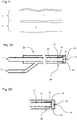
- Fig. 2 shows a first embodiment of an application instrument 10 according to the invention.
- An essential component of the application instrument 10 is the probe shaft 14, which is preferably at least partially elastic and has an instrument head 20 proximally.
- This instrument head 20 has a nozzle 23 for the delivery of fluids.
- the fluids can be a saline solution or the above-mentioned suspension with cell proportions.
- an inner supply channel 21 is arranged coaxially in the lumen of the probe shaft 14.
- the outer area of the inner feed channel 21 forms the outer feed channel 22, which surrounds the inner feed channel 21.
- the inner supply passage 21 is in the state as shown in FIG Fig. 2A
- a shuttle valve 25 located at the distal tip of the inner supply passage 21 allows leakage of a first fluid from the inner passage 21 into the distal reservoir 24 and seals fluid communication between the distal reservoir 24 and the distal reservoir 24 Outdoor supply channel 22.
- the inner supply channel 21 is supplied via a first inlet 11, and the outer supply channel 22 via a second inlet 12 with the first and second fluid.
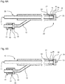
- Fig. 2B shows a detailed view of the instrument head 20 from Fig. 2A , In contrast to the illustration according to Fig. 2A closes the shuttle valve 25 in Fig. 2B the side openings 26 so that there is an immediate fluid connection between the distal reservoir 24 and the outer supply passage 22.
- One aspect of the present invention is to deliver the supplied fluids in an approximately perfect pulse shape via an outlet opening 23, the nozzle 23.
- the instrument head 20 according to the invention makes it possible, at relatively low pressures, to deliver fluid pulses with which the fluids can penetrate into the target tissue in a suitable manner. Due to the efficient use of existing pressures, the cell suspension is "spared" in the application.
- Another aspect of the invention consists in introducing the fluids, in particular the cell suspension, into different planes of the target tissue by means of the control of the pulses. Due to the efficient use of the existing pressures, the cell suspension can be introduced into the target tissue, in particular at various points, during application.
- the first fluid first promoted in a first time interval T1 with a high pressure ph.
- the instrument head 20 is in the state as shown in FIG Fig. 2A is shown.
- the first fluid exits the inner supply channel 21, fills the distal reservoir 24 and is discharged via the nozzle 23 with a defined nozzle diameter.
- the first fluid thus hits the tissue with a high kinetic energy and can be used to create a delivery channel.
- the second fluid is driven at a very low pressure pz, so that the distal reservoir 24 fills with the second fluid, ie the suspension.
- the instrument head 20 can assume the state as in Fig. 2B is shown.
- the shuttle valve 25 closes the inner supply passage 21, so that the running of the first fluid is prevented.
- the first fluid in the third time interval T3 is delivered with a pressure p1.
- This pressure pl is preferably significantly lower than the high pressure ph, so that a gentle application of the suspension takes place.
- the instrument head 20 again assumes the state as in Fig. 2A is shown.
- the first fluid enters the distal reservoir 24 and displaces the second fluid.
- the first fluid is thus propellant and serves to expel the second fluid at a given pressure pz.
- the distal memory 24 can be filled once more in an application time interval (compare fourth time interval T4) and the suspension can be dispensed one more time (compare time interval T5).
- Fig. 3A shows a further embodiment of the inventive application instrument 10. Compared to the embodiment of the FIGS. 2A and 2B is in the embodiment according to Fig. 3A another valve in the instrument head 20 is provided. The other valve, a check valve 25 ', is located as well as the shuttle valve 25 in the outer supply passage 22. Opposite the shuttle valve 25, the check valve 25' is located less close to the distal tip of the application instrument 10. The check valve 25 'is a rubber lip which closes the outer supply passage 22 completely in the pressure-free state.
- Fig. 3A shows a corresponding pressure-free state in which the first fluid is conveyed and discharged via the nozzle 23.
- the described embodiment can be used in a particularly advantageous manner with an elastic nozzle 23, as exemplified in the FIGS. 4A and 4B is shown.
- the elastic nozzle 23 can also have independent of an existing or non-existent check valve 25 'advantages.
- the elastic nozzle 23 according to Fig. 4A is closed in the pressure-free state.
- the elastic nozzle body is installed in the application instrument 10 such that a defined pressure acts radially on the nozzle body and closes the nozzle opening in the initial state. If the pressure rises proximally of the nozzle body in the distal reservoir 24, for example as a result of the supply of the second fluid, then the nozzle body is initially slightly curved outward, without the nozzle opening being opened (not shown).
- a defined volume amount in the distal memory 24 can be predosed. Subsequently, as already described, the predosed volume can be introduced into the channel opened in the tissue with a subsequent high-pressure pulse (compare third or fifth time interval T3, T5).
- the nozzle body described in this embodiment has a circumferential lip which tapers in the radial direction.
- the nozzle body can also be constructed in two parts.
- the circumferential lip may be made of an elastic material while being comprised at its base by a hard material carrier.
- the elastic nozzle 23 is designed such that a sufficient elongation and thus the admission of a predosing volume in the distal reservoir 24 can be achieved without a high pressure, For example, higher than 20 bar is required.
- the elastic nozzle is designed so that in the open state, the nozzle opening 23 is just so large that a nozzle effect, so a sufficient acceleration of the fluid can be achieved.
- the elastic nozzle 23 can be used to prevent overflow of the fluid after application of the first and / or second fluid. At the same time it stores with appropriate filling of the distal memory 24 a certain form that can be retrieved. Furthermore, the elastic nozzle 23 minimizes the risk of clogging of the application instrument 10.
- the blockage leads in the embodiment according to the invention only to an increase in pressure, which in turn causes an expansion of the nozzle 23 in such a way that contaminant particles can pass.
- Fig. 4B shows the instrument head 20 with the elastic nozzle 23 open, for example during the third time interval T3.
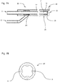
- Fig. 5 shows an alternative embodiment of the instrument head according to FIGS. 4A and 4B ,
- the outer supply passage 22 serves to supply the first fluid and the inner supply passage 21 to supply the second fluid.
- the in Fig. 5 For example, the condition shown occurs in the first time interval T1 when the first fluid is used to create a tissue channel.
- the inner fluid supply channel 21 for the second fluid, and the outer fluid supply channel 22 for the first fluid can be used.
- FIGS. 6A and 6B show a further embodiment according to the invention, in which an elastic element is used as a second passive valve.
- a ventilation device 40 In the second inlet, a ventilation device 40.
- Essential components of the ventilation device 40 are a ventilation chamber 44, in which the second inlet 12 opens, a ventilation opening 41 and a ventilation valve 45.
- the function of the ventilation opening 41 is controlled by means of the ventilation valve 45.
- the ventilation opening 41 allows a venting of the second inlet 12 and thus at least a portion of the outer supply channel 22. If the second inlet 12 is pressurized, the vent valve 45 closes after retrograde from (sealing effect between the second inlet 12 and vent 41). Distal of the vent valve 45 prevails in the aeration chamber 44, an overpressure.
- the second fluid may flow toward the instrument head and be dispensed (eg, during the third time interval T3). This condition is in the Fig. 6A shown.
- the venting valve 45 changes into its initial state and closes off the proximal part of the second inlet 12 with respect to the aeration chamber 44 (cf. Fig. 6B ).
- the overpressure in the distal region of the second inlet 12 is reduced very rapidly via the ventilation opening 41.
- the wake from the nozzle 23 is stopped very quickly, ideally prevented, since the flow resistance of the ventilation opening 41 is significantly lower than that of the nozzle 23.
- the pressure flank of the discharged and pulsed fluid jet can drop very steeply.
- the shuttle valve 25 closes the outer supply passage 22 in this state, only very small amounts of the second fluid escape through the ventilation opening 41.
- a plurality of ventilation openings 41 can also be provided according to the invention.
- the vent valve 45 is not a passive but an active valve or a control valve.
- a solenoid valve that fulfills the function of the ventilation valve 45 can be provided in the handle of the application instrument 10. This solenoid valve can by a supply device 50 (see. Fig. 10 ) to be controlled.
- the Fig. 7A shows an embodiment of the application instrument 10, which in its operation of the FIGS. 3A and 3B is similar.
- the check valve 25 ' is formed by an elastic member at an orifice of the second inlet 12 into the outer supply passage 22.
- the elastic element is designed such that in a starting state, not shown, a pressure for closing the second inlet 12 results. The voltage achieved thereby produces a sealing effect in the pressureless state. If the second inlet 12 is pressurized, the elastic element deforms (see illustration of FIGS Fig. 7A ) and thus opens the fluid connection to the outer supply channel 22. When the pressure in the second inlet 12 decreases again, the restoring forces bring the elastic element after falling below a specific pressure threshold in the initial state and the check valve 25 'closes.
- the elastic element consists of an elastic hose section.
- reinforcement structures such as those in Fig. 7B shown running in the direction of the longitudinal axis ribs 5 and / or reinforcing fibers 6 of a relatively rigid material, a higher contact pressure and thus a higher closing force of the check valve 25 'can be achieved.
- the 8A, 8B, 8C show different embodiments of the shuttle valve 25.
- this is formed by elastic material which is arranged on the outside of the inner feed channel 21 and closes these opening side openings 26.
- the embodiment according to Fig. 8A shows an elastic tube 30 which is slipped over the distal end of the inner feed channel 21 in sections. A fixation of the elastic tube 30 via a clamping ring 31.
- An essential aspect of the embodiment according to Fig. 8A it is that the elastic tube 30 extends partially beyond the distal end of the inner feed channel 21. The end result is a first section 34, on which the elastic tube rests on the inner supply channel 21 and a second section 35, in the course of which the elastic tube 30 narrows.
- the elastic tube 30 thus extends over a sealing edge 32 with a particularly high surface pressure. As a result, a better sealing effect is achieved.
- the inner supply channel 21 has a radially outwardly projecting thickening in sections. This thickening is arranged at the location at which the side openings 26 are located. Proximal and distal to the thickening of the inner supply channel 21 has a smaller diameter.
- the elastic tube 30 thus results in a first portion 34 of larger diameter, a second portion 35 with a small diameter and a third portion 36 with a small diameter.
- the diameters of the second and third sections 35 and 36 may be identical. In another embodiment (not shown), the Diameter of the second and third sections 35 and 36 also have different values.
- first portion 34 and the second 35 and / or the third portion 36 results in a sealing edge 32, which improves the closing function of the shuttle valve 25.
- the larger diameter in the first portion 34 causes a pre-strain and bias of the elastic member, which also causes a better sealing effect.
- a higher surface pressure can also be achieved by cylinder segments which surround the side openings 26 of the inner feed channel 21 (cf. Fig. 8C ). In the end, these cylinder segments also form sealing edges 32, which improve the closing function of the valve.
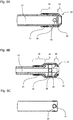
- the Figs. 9A and 9B show further embodiments of the application instrument 10, in particular the instrument head 20.
- the probe shaft 14 is here a multi-lumen tube (shown is a two-lumen tube). In this embodiment, therefore, there are no coaxially arranged channels comprising the inner feed channel 21 and the outer feed channel 22. Instead, a first feed channel 21 'for the first fluid is parallel to a second feed channel 22'. Between the first supply channel 21 'and the second supply channel 22', a partition wall 28 is provided. In the embodiment shown, the cross-sectional area of the first supply channel 21 'differs significantly from that of the second supply channel 22'. For example, the first supply channel 21 'may have twice as large a cross-sectional area as the second supply channel 22'.
- the cross-sectional profile of the first supply channel 21 ' can be more than twice as large as the cross-sectional profile of the second supply channel 22'.
- In the tapered portion ( support member) is an elastic member for forming a Lip check valve 25 is arranged. In the end, this results in a bidirectional valve that takes over the function of the previously described shuttle valve 25.
- the lip check valve is preferably axially fixed in the first supply channel 21 'by the support member made of a hard (non-elastic) material.
- the inner contour of the tapered section largely corresponds to the outer contour of the distal part of the lip check valve.
- the opening of the tapered section is dimensioned such that in the initial state (the elastic element is as in Fig. 9A shown, not stretched) results in a gap between the lips of the elastic member and the inner wall of the support member.
- the elastic element is as in Fig. 9A shown, not stretched
- the pressure ratios of the first supply channel 21 ' are decoupled in this state from the pressure ratios of the second supply channel 22'. If the pressure in the first supply channel 21 'drops (for example, after the first time interval T1), then the shuttle valve 25 returns to the initial state, so that the side opening 26, as shown in FIG Fig. 9B shown is released. In the second time interval T2, the second fluid can flow through the gap almost unhindered, so that it is possible to fill the distal reservoir 24 at low pressure. Since the elastic element now works in the reverse direction, it again acts as a barrier between the first supply channel 21 'and the second supply channel 22'. Preferably, the gap is dimensioned such that the second fluid can flow unhindered, at low pressure, and on the other hand, the shuttle valve 25 is securely closed to prevent entry of the second fluid into the first supply channel 21 '.
- valve action can also be achieved by the use of an internal valve in combination with a ball valve. Both valves are arranged one behind the other in a lumen (preferably the larger one). The ball valve is located proximally relative to the elastic element. In this arrangement, each of the valves takes over the blocking of the fluid in one direction, while the flow takes place unhindered in the other direction.
- Fig. 10 shows a supply device 50, which is connected via the first inlet 11 and the second inlet 12 with one of the described application instruments 10.
- a medium separating device 60 is provided in the second inlet, so that the supply device can deliver the first fluid, preferably saline, via different ports, whereby depending on the selected inflow, different fluids ultimately arrive at the application instrument 10 (in the first inflow 11 the first fluid and in the second inlet 12 the second fluid).
- control method can be designed to also offer a corresponding control strategy during the fourth delivery interval T4 and during the fifth delivery interval T5 (cf. Fig. 17 ).
- the controller 51 interacts with a fluid source, for example a pump 52, a first control valve 55 and a second control valve 55 '.
- a fluid source for example a pump 52, a first control valve 55 and a second control valve 55 '.
- the pump 52 is in fluid communication with a pressure accumulator 53 of the supply device 50.
- the pump 52 operates continuously and is flow-controlled.
- the control of the first control valve 55 which is in fluid communication with the pressure accumulator 53, makes it possible to specify a desired pulse shape (frequency, duty cycle, effective pulse power).
- the flow control of the pump causes a constant volume flow of the first fluid within the supply device 50, regardless of the switching position of the first control valve 55.
- the first control valve 55 is preferably a 3/2-way valve, which establishes a fluid connection between pressure accumulator 53 and a second control valve 55 'via a pressure line 54 in the energized state.
- the first control valve 55 essentially serves to build up a desired pressure level, while the second control valve 55 'applies the predetermined pressure level to the first inlet or the second inlet 12.
- the first control valve 55 there is a fluid connection between the pressure accumulator 53 - thus also with the pump 52 - and a first bypass line BY1. Via the bypass line BY1, the fluid flow is discharged, so that no unauthorized operating state for the pump 52 occurs.
- the first bypass line is BY1, as in FIG Fig. 10 shown equipped with a throttle valve 58 which ensures that a certain pressure level in the system section is held in front of the first control valve 55. To set this pressure level can manually or via the controller 51 (see. Fig. 13 ) a hydraulic resistance at the throttle valve 58 can be adjusted.
- the resistor is preset.
- a very steep pulse edge can be achieved at the nozzle 23.
- the pressure increase can compensate for pressure losses in the inlets 11, 12.
- the pressure increase must be chosen so that, although a rapid increase in force is achieved, the desired pressure at the nozzle 23 but not exceeded.
- the pressure in the energized state spreads via the pressure lines 54 to the second control valve 55 'from.
- the second control valve 55 selects an inlet 11, 12 from.
- the effect of pressure exaggeration can be used to perform an initial perforation of the biological tissue as a preparatory step for the subsequent substance entry.
- the supply device thus generates a steeply rising pressure profile, which drops over time.
- the second control valve 55 ' is switched so that over the course of the falling pressure flank only a perforation of the tissue (first time interval T1), then a filling of the distal memory 24 (second time interval T2) and finally the entry of the substance (third time interval T3) he follows.
- the second control valve 55 ' is integrated into the instrument 10.
- control of the second control valve 55 'still takes place via the controller 51.
- the first control valve 55 is additionally integrated into the application instrument.
- the arrangement of the first control valve 55 is selected so that it shuts off the connection between the pressure line 54 and the pump 52 in the de-energized state.
- the pressure line 54 is thus pressureless during the bypass phases ÜD1, ÜD2, or subjected to a residual pressure.
- This arrangement has two advantages. First, the first control valve 55 only has to be energized only briefly during the activation for the delivery of a pulse train. Second, the pressure level set by the throttle valve 58 is already available at the first pulse delivered.
- Fig. 12 illustrates another embodiment for the effective generation of fluid pulses. In this embodiment, a 2-way valve is used as the first control valve 55. As in the previously described embodiment, there is a fluid connection between the pump 52 and the pressure accumulator 53. Further, there is a fluid connection from the pressure accumulator to the first control valve 55 in the form of a 2/2-way valve.
- the 2/2-way valve is used to deliver a water jet pulse with a defined duration, while the pressure relief valve 59 allows the generation of a desired pressure level during the bypass phases, ÜD1 ÜD2.
- the pressure relief valve 59 can be adjusted so that this releases the first bypass line upon reaching a certain pressure, so that the pressure can be reduced.
- the overpressure valve 59 can assume a regulator function, which is preferably controlled by the controller 51.
- the pressure-pressure-flow characteristic curve of the overpressure valve 59 can be designed so that a certain pressure drops at the valve as it flows through the valve.
- the pressure relief valve 59 is completely dispensed with.
- Fig. 13 shows a further embodiment, wherein two 2/2-way valves are used.
- the first control valve 55 is designed as a 2/2-way valve and still serves to control the transfer of existing pressure in the system to the application instrument 10.
- a third control valve - also a 2/2-way valve - allows one Pressure adjustment within the system by releasing or closing the first BY1 bypass.
- the third control valve 55 "can contribute significantly to build up a certain overpressure.
- a further bypass line BY2 can be provided on the side of the first control valve which is remote from the flow.
- Fig. 14 shows a corresponding embodiment of the valve assembly in an initial state wherein the valves are controlled according to the application step.
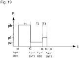
- a fourth control valve 55 "' enables targeted and rapid removal of the existing pressure in the inlets 11, 12' Fig. 19 are shown.
- the first control valve 55 is closed to stop the pulse (time t2).
- the fourth control valve 55 "'is opened to provide a fluid connection to the second bypass line BY2, thereby implementing the first venting phase ENT1
- the fall time is very low and results in immediate pressure reduction, for example, in the distal memory 24.
- Fig. 15 shows an embodiment in which a 2/2-way valve is used as the first control valve 55.
- the 2/2-way valve is integrated in the bypass line BY1, while the application instrument 10 is connected directly to the pump.
- One advantage of this design is that venting phases ENT1, ENT2 can also be implemented here for rapid pressure drop. Compared to the embodiments described so far, this embodiment is very simple and robust.
- Fig. 16 shows a further embodiment of the supply device 50 according to the invention.
- two 3/2-way valves are used to implement the functionality already described.
- the active valves or control valves described may have an electromagnetic drive or other drive known in the art.
- piezo actuators, a pneumatic drive unit or the like may be used.
- the embodiments may be combined with each other in any manner.
- needle valves, diaphragm valves, rocker valves and others can be used.
- a pinch valve can be used, which is preferred due to its sterilizability.
- the second time interval T2 is used in each case to fill the distal memory 24.
- the distal memory 24 is refilled in the fourth time interval T4.
- the fourth time interval T4 there is no corresponding refilling.
- Fig. 19 shows the timing of the bypass phases BY1, BY2 and the venting phase ENT1, ENT2 relative to the time intervals T1 to T5.
- the first bypass phase ends with the beginning of the first time interval T1 at time t1.
- the first venting phase ENT1 starts at the end of the first time interval T1 at time t2.
- the second bypass phase BY2 begins, which ends at the time t3 with the beginning of the third time interval T3.
- the second deaeration phase ENT2 begins at time t4 and ends at time t5.
Landscapes
- Health & Medical Sciences (AREA)
- Life Sciences & Earth Sciences (AREA)
- Heart & Thoracic Surgery (AREA)
- General Health & Medical Sciences (AREA)
- Engineering & Computer Science (AREA)
- Veterinary Medicine (AREA)
- Biomedical Technology (AREA)
- Public Health (AREA)
- Animal Behavior & Ethology (AREA)
- Anesthesiology (AREA)
- Hematology (AREA)
- Vascular Medicine (AREA)
- Surgery (AREA)
- Pulmonology (AREA)
- Nuclear Medicine, Radiotherapy & Molecular Imaging (AREA)
- Molecular Biology (AREA)
- Medical Informatics (AREA)
- Biophysics (AREA)
- Pathology (AREA)
- Physics & Mathematics (AREA)
- Optics & Photonics (AREA)
- Radiology & Medical Imaging (AREA)
- Surgical Instruments (AREA)
- Infusion, Injection, And Reservoir Apparatuses (AREA)
- Gastroenterology & Hepatology (AREA)
Priority Applications (10)
| Application Number | Priority Date | Filing Date | Title |
|---|---|---|---|
| PL14200435T PL3040036T3 (pl) | 2014-12-29 | 2014-12-29 | Głowica przyrządu, przyrząd do aplikacji z odpowiednią głowicą przyrządu i system aplikacji |
| PL17158128T PL3189800T3 (pl) | 2014-12-29 | 2014-12-29 | Pamięć czytelna dla komputera wraz z instrukcjami dotyczącymi wdrożenia procedury kontrolnej dot. obsługi urządzenia zasilającego dla odpowiedniego przyrządu (instrumentu) aplikacyjnego |
| EP17158128.3A EP3189800B1 (de) | 2014-12-29 | 2014-12-29 | Computerlesbarer speicher mit instruktionen zur implementierung eines steuerverfahrens zum betreiben einer versorgungseinrichtung |
| EP14200435.7A EP3040036B1 (de) | 2014-12-29 | 2014-12-29 | Instrumentenkopf, Applikationsinstrument mit entsprechendem Instrumentenkopf und Applikationssystem |
| CN201510883199.1A CN105727424B (zh) | 2014-12-29 | 2015-12-04 | 器械头、具有所述器械头的应用器械、应用系统和操作供应系统的方法 |
| US14/976,084 US10549041B2 (en) | 2014-12-29 | 2015-12-21 | Instrument head, application instrument having said instrument head, application system and method of operating a supply system |
| BR102015032300-0A BR102015032300B1 (pt) | 2014-12-29 | 2015-12-22 | Instrumento de aplicação de jato de água de primeiro e segundo fluidos com uma cabeça de instrumento, método de controle para operar um sistema de fornecimento e meio legível por computador não-transitório |
| KR1020150185574A KR101960133B1 (ko) | 2014-12-29 | 2015-12-24 | 기구 헤드, 기구 헤드를 가지는 투약 기구, 투약 시스템, 및 공급 시스템을 동작시키는 방법 |
| JP2015253647A JP6367787B2 (ja) | 2014-12-29 | 2015-12-25 | 器具ヘッド、前記器具ヘッドを有する施与器具、及び施与システム |
| US16/730,714 US12048833B2 (en) | 2014-12-29 | 2019-12-30 | Methods for injecting fluids |
Applications Claiming Priority (1)
| Application Number | Priority Date | Filing Date | Title |
|---|---|---|---|
| EP14200435.7A EP3040036B1 (de) | 2014-12-29 | 2014-12-29 | Instrumentenkopf, Applikationsinstrument mit entsprechendem Instrumentenkopf und Applikationssystem |
Related Child Applications (2)
| Application Number | Title | Priority Date | Filing Date |
|---|---|---|---|
| EP17158128.3A Division EP3189800B1 (de) | 2014-12-29 | 2014-12-29 | Computerlesbarer speicher mit instruktionen zur implementierung eines steuerverfahrens zum betreiben einer versorgungseinrichtung |
| EP17158128.3A Division-Into EP3189800B1 (de) | 2014-12-29 | 2014-12-29 | Computerlesbarer speicher mit instruktionen zur implementierung eines steuerverfahrens zum betreiben einer versorgungseinrichtung |
Publications (2)
| Publication Number | Publication Date |
|---|---|
| EP3040036A1 EP3040036A1 (de) | 2016-07-06 |
| EP3040036B1 true EP3040036B1 (de) | 2017-10-11 |
Family
ID=52282556
Family Applications (2)
| Application Number | Title | Priority Date | Filing Date |
|---|---|---|---|
| EP14200435.7A Active EP3040036B1 (de) | 2014-12-29 | 2014-12-29 | Instrumentenkopf, Applikationsinstrument mit entsprechendem Instrumentenkopf und Applikationssystem |
| EP17158128.3A Active EP3189800B1 (de) | 2014-12-29 | 2014-12-29 | Computerlesbarer speicher mit instruktionen zur implementierung eines steuerverfahrens zum betreiben einer versorgungseinrichtung |
Family Applications After (1)
| Application Number | Title | Priority Date | Filing Date |
|---|---|---|---|
| EP17158128.3A Active EP3189800B1 (de) | 2014-12-29 | 2014-12-29 | Computerlesbarer speicher mit instruktionen zur implementierung eines steuerverfahrens zum betreiben einer versorgungseinrichtung |
Country Status (7)
| Country | Link |
|---|---|
| US (2) | US10549041B2 (enExample) |
| EP (2) | EP3040036B1 (enExample) |
| JP (1) | JP6367787B2 (enExample) |
| KR (1) | KR101960133B1 (enExample) |
| CN (1) | CN105727424B (enExample) |
| BR (1) | BR102015032300B1 (enExample) |
| PL (2) | PL3189800T3 (enExample) |
Families Citing this family (7)
| Publication number | Priority date | Publication date | Assignee | Title |
|---|---|---|---|---|
| EP3714926A1 (de) * | 2019-03-28 | 2020-09-30 | Erbe Elektromedizin GmbH | Instrument, instrumentenkopf, applikationssystem und verfahren |
| EP3782528B1 (en) * | 2019-08-23 | 2023-04-19 | Chang Gul Hong | Fluid supply device for endoscope |
| EP3912709B1 (de) * | 2020-05-19 | 2024-02-14 | Heraeus Medical GmbH | Vorrichtung und verfahren zum mischen von flüssigkeiten |
| US12178996B2 (en) * | 2020-09-18 | 2024-12-31 | Carefusion 303, Inc. | Pressure actuated uni-directional flow control device for gravity IV sets |
| EP4134113A1 (de) * | 2021-08-10 | 2023-02-15 | Erbe Elektromedizin GmbH | Applikator mit dosiereinheit |
| US20250195106A1 (en) * | 2021-08-16 | 2025-06-19 | Fisher & Paykel Healthcare Limited | Accessory for arranging a surgical instrument within a cannula shaft |
| EP4162890B1 (de) * | 2021-10-08 | 2025-07-16 | Erbe Elektromedizin GmbH | Instrumentenanschlusseinrichtung und verfahren zur herstellung derselben |
Family Cites Families (31)
| Publication number | Priority date | Publication date | Assignee | Title |
|---|---|---|---|---|
| US5312332A (en) * | 1992-10-09 | 1994-05-17 | Symbiosis Corporation | Endoscopic surgical methods utilizing a suction-irrigation instrument with a port for endoscopic manipulating instruments |
| US5911703A (en) * | 1997-05-22 | 1999-06-15 | Avant Drug Delivery Systems, Inc. | Two-stage fluid medicament jet injector |
| CA2301545A1 (en) | 1997-08-22 | 1999-03-04 | Vincent Decrescito | An apparatus for preventing loss of a composition during a medical procedure |
| GB0208840D0 (en) | 2002-04-18 | 2002-05-29 | Novamedix Distrib Ltd | Fluid control valve |
| US7118566B2 (en) * | 2002-05-16 | 2006-10-10 | Medtronic, Inc. | Device and method for needle-less interstitial injection of fluid for ablation of cardiac tissue |
| US7842028B2 (en) | 2005-04-14 | 2010-11-30 | Cambridge Endoscopic Devices, Inc. | Surgical instrument guide device |
| EP1711217A1 (en) * | 2004-01-26 | 2006-10-18 | Novo Nordisk A/S | Impulse chamber for jet delivery device |
| US7302960B2 (en) * | 2005-10-26 | 2007-12-04 | Smiths Medical Asd, Inc. | Momentary high pressure valve |
| GB0610666D0 (en) * | 2006-05-30 | 2006-07-05 | Glaxo Group Ltd | Fluid dispenser |
| WO2008143828A1 (en) * | 2007-05-14 | 2008-11-27 | Clyde Meriwether Smith | Systems and methods for supplying and/or dispensing fluid |
| US9271751B2 (en) * | 2007-05-29 | 2016-03-01 | Ethicon Endo-Surgery, Llc | Ultrasonic surgical system |
| DE102008025233A1 (de) * | 2008-05-27 | 2009-12-03 | Erbe Elektromedizin Gmbh | Wasserstrahlchirurgieinstrument |
| EP2274039A2 (en) * | 2008-05-06 | 2011-01-19 | Wilson-Cook Medical Inc. | Apparatus and methods for delivering therapeutic agents |
| EP2375960B1 (en) * | 2008-12-23 | 2018-10-31 | Cook Medical Technologies LLC | Apparatus for containing and delivering therapeutic agents |
| EP2283885A1 (en) * | 2009-08-11 | 2011-02-16 | Sanofi-Aventis Deutschland GmbH | Dosing unit for an injection device |
| US8491526B2 (en) | 2010-05-13 | 2013-07-23 | Ethicon Endo-Surgery, Inc. | Therapeutic cell applicator instrument with modular tips |
| FR2960415B1 (fr) | 2010-05-27 | 2012-12-28 | Nestis | Generateur de jets pulses haute pression d'un liquide en vue d'applications medicales et chirugicales |
| CN103298507B (zh) * | 2010-10-07 | 2015-08-26 | 麻省理工学院 | 采用线性洛仑兹力致动的无针射流注射系统递送固体和/或流体 |
| DE102011007314B4 (de) * | 2011-04-13 | 2015-05-07 | Jürgen Stockmar | Vorrichtung zum Einspritzen eines Mediums in oder unter die Haut mit einer Serie von Druckimpulsen |
| US9358337B2 (en) | 2011-05-24 | 2016-06-07 | Sanofi - Aventis Deutschland GmbH | Check valve arrangement |
| US9520445B2 (en) * | 2011-07-12 | 2016-12-13 | Helmholtz-Zentrum Dresden-Rossendorf E. V. | Integrated non-volatile memory elements, design and use |
| KR101322104B1 (ko) | 2011-09-08 | 2013-10-28 | 주식회사 모바수 | 착탈 가능한 엔드 이펙터를 갖는 최소 침습 수술 기구 |
| CN104053467B (zh) | 2011-11-23 | 2017-06-09 | 赛诺菲-安万特德国有限公司 | 用于调节流体药物的剂量的方法和医用装置 |
| DE102012013464A1 (de) * | 2012-05-07 | 2013-11-07 | Heraeus Medical Gmbh | Lavage-System mit Düse |
| US9878105B2 (en) * | 2012-05-16 | 2018-01-30 | Sanofi-Aventis Deutschland Gmbh | Dispense interface |
| HK1202823A1 (en) | 2012-05-16 | 2015-10-09 | Sanofi-Aventis Deutschland Gmbh | Dispense interface |
| US9629748B2 (en) * | 2012-05-31 | 2017-04-25 | Medical Instrument Development Laboratories, Inc. | Multi-stage tubing for high-speed pneumatic surgical cutter |
| KR101575039B1 (ko) * | 2012-07-19 | 2015-12-07 | (주)아모레퍼시픽 | 노즐 장치 및 이를 포함하는 최소 침습형 주입 장치 |
| WO2014137383A1 (en) | 2013-03-04 | 2014-09-12 | Csa Medical, Inc. | Cryospray catheters |
| US20140276534A1 (en) * | 2013-03-14 | 2014-09-18 | Nova Pneumatics LLC | Needleless injector |
| WO2014191842A2 (en) | 2013-05-07 | 2014-12-04 | Jet Prep Ltd. | Rigid head for a body passage device |
-
2014
- 2014-12-29 EP EP14200435.7A patent/EP3040036B1/de active Active
- 2014-12-29 PL PL17158128T patent/PL3189800T3/pl unknown
- 2014-12-29 EP EP17158128.3A patent/EP3189800B1/de active Active
- 2014-12-29 PL PL14200435T patent/PL3040036T3/pl unknown
-
2015
- 2015-12-04 CN CN201510883199.1A patent/CN105727424B/zh active Active
- 2015-12-21 US US14/976,084 patent/US10549041B2/en active Active
- 2015-12-22 BR BR102015032300-0A patent/BR102015032300B1/pt active IP Right Grant
- 2015-12-24 KR KR1020150185574A patent/KR101960133B1/ko active Active
- 2015-12-25 JP JP2015253647A patent/JP6367787B2/ja active Active
-
2019
- 2019-12-30 US US16/730,714 patent/US12048833B2/en active Active
Non-Patent Citations (1)
| Title |
|---|
| None * |
Also Published As
| Publication number | Publication date |
|---|---|
| KR20160080078A (ko) | 2016-07-07 |
| PL3189800T3 (pl) | 2019-11-29 |
| US12048833B2 (en) | 2024-07-30 |
| JP6367787B2 (ja) | 2018-08-01 |
| PL3040036T3 (pl) | 2018-03-30 |
| US20160184524A1 (en) | 2016-06-30 |
| US20200129700A1 (en) | 2020-04-30 |
| EP3189800B1 (de) | 2019-04-03 |
| US10549041B2 (en) | 2020-02-04 |
| EP3189800A1 (de) | 2017-07-12 |
| BR102015032300B1 (pt) | 2022-01-25 |
| JP2016123863A (ja) | 2016-07-11 |
| EP3040036A1 (de) | 2016-07-06 |
| CN105727424B (zh) | 2020-07-24 |
| CN105727424A (zh) | 2016-07-06 |
| KR101960133B1 (ko) | 2019-03-19 |
| BR102015032300A2 (pt) | 2016-07-05 |
Similar Documents
| Publication | Publication Date | Title |
|---|---|---|
| EP3040036B1 (de) | Instrumentenkopf, Applikationsinstrument mit entsprechendem Instrumentenkopf und Applikationssystem | |
| EP3040101B1 (de) | Versorgungseinrichtung zur Erzeugung eines gepulsten Fluidstrahls, Applikationssystem mit Versorgungseinrichtung und computerlesbarer Speicher | |
| DE2709112C3 (de) | Vorrichtung und Verfahren zum Einspritzen von Schaum in eine zu reinigende Rohrleitung | |
| DE69820189T2 (de) | System und Verfahren für Sprüh- oder Aerosolspitze mit Einweg-Strömung | |
| EP1484039B1 (de) | Einrichtung zur Erzeugung einer künstlichen Verengung im Gastro-Intestinal-Trakt | |
| EP2981365B1 (de) | Pulverdichtstrompumpe und entsprechendes betriebsverfahren | |
| EP3010645B1 (de) | Pulverfördervorrichtung für beschichtungspulver | |
| DE69927153T2 (de) | VERFAHREN ZUR ERZEUGUNG EINER PULSFOLGE EINES STERILEN FLÜSSIGKEITSSTRAHLS Für MEDIZINISCHE ZWECKE | |
| EP1906013A2 (de) | Dosierpumpe, Spritzvorrichtung zum Versprühen von Spritzmitteln sowie Verfahren zum Betreiben einer solchen Spritzvorrichtung | |
| WO2015155304A1 (de) | Pneumatische kompakt-vakuumtoilette | |
| DE102013205895A1 (de) | Pulverdichtstrompumpe zum Fördern von Beschichtungspulver sowie entsprechendes Verfahren | |
| DE202015102187U1 (de) | Vorrichtung zum Transfer eines Fluids | |
| DE102020109973A1 (de) | Beschichtungsmittelpumpe, Beschichtungsanlage und zugehöriges Betriebsverfahren | |
| DE102017220030A1 (de) | Spritzeinrichtung | |
| EP3714926A1 (de) | Instrument, instrumentenkopf, applikationssystem und verfahren | |
| WO1997017010A1 (de) | Verfahren und vorrichtung zum spülen | |
| DE102009033525A1 (de) | Druckgasbetriebenes Instrument, insbesondere chirurgisches Instrument | |
| DE102015108492A1 (de) | Verfahren zum Betreiben einer Pulverdichtstrompumpe sowie Pulverdichtstrompumpe | |
| DE102019203102A1 (de) | Spritzeinrichtung und Verfahren | |
| DE102009033524A1 (de) | Druckgasbetriebenes Instrument | |
| DE102004008495A1 (de) | Pulverförderpumpe | |
| DE102009011561A1 (de) | Barriere zur Implantation im Knochen, insbesondere für die Vertebroplastie | |
| AT511731B1 (de) | Kavitationsoptimierte drosselbohrungen | |
| WO2025108676A1 (de) | Mischeinrichtung für ein mehrkomponentenmaterial und zugehöriges betriebsverfahren | |
| WO2018029078A1 (de) | Vorrichtung zum erzeugen eines pulsierenden hydraulikfluiddruckes |
Legal Events
| Date | Code | Title | Description |
|---|---|---|---|
| PUAI | Public reference made under article 153(3) epc to a published international application that has entered the european phase |
Free format text: ORIGINAL CODE: 0009012 |
|
| 17P | Request for examination filed |
Effective date: 20141229 |
|
| AK | Designated contracting states |
Kind code of ref document: A1 Designated state(s): AL AT BE BG CH CY CZ DE DK EE ES FI FR GB GR HR HU IE IS IT LI LT LU LV MC MK MT NL NO PL PT RO RS SE SI SK SM TR |
|
| AX | Request for extension of the european patent |
Extension state: BA ME |
|
| 17Q | First examination report despatched |
Effective date: 20161019 |
|
| RAP1 | Party data changed (applicant data changed or rights of an application transferred) |
Owner name: ERBE ELEKTROMEDIZIN GMBH |
|
| GRAP | Despatch of communication of intention to grant a patent |
Free format text: ORIGINAL CODE: EPIDOSNIGR1 |
|
| RIC1 | Information provided on ipc code assigned before grant |
Ipc: A61M 5/31 20060101ALI20170301BHEP Ipc: A61M 39/24 20060101ALI20170301BHEP Ipc: A61M 5/14 20060101ALI20170301BHEP Ipc: A61M 39/22 20060101ALI20170301BHEP Ipc: A61M 5/19 20060101ALI20170301BHEP Ipc: A61M 5/178 20060101ALI20170301BHEP Ipc: A61M 5/20 20060101ALI20170301BHEP Ipc: A61B 17/32 20060101ALI20170301BHEP Ipc: A61B 1/015 20060101ALI20170301BHEP Ipc: A61B 17/3203 20060101AFI20170301BHEP Ipc: A61M 5/30 20060101ALI20170301BHEP |
|
| INTG | Intention to grant announced |
Effective date: 20170321 |
|
| GRAS | Grant fee paid |
Free format text: ORIGINAL CODE: EPIDOSNIGR3 |
|
| GRAJ | Information related to disapproval of communication of intention to grant by the applicant or resumption of examination proceedings by the epo deleted |
Free format text: ORIGINAL CODE: EPIDOSDIGR1 |
|
| GRAL | Information related to payment of fee for publishing/printing deleted |
Free format text: ORIGINAL CODE: EPIDOSDIGR3 |
|
| REG | Reference to a national code |
Ref country code: DE Ref legal event code: R079 Ref document number: 502014005759 Country of ref document: DE Free format text: PREVIOUS MAIN CLASS: A61B0017320000 Ipc: A61M0005168000 |
|
| GRAR | Information related to intention to grant a patent recorded |
Free format text: ORIGINAL CODE: EPIDOSNIGR71 |
|
| GRAA | (expected) grant |
Free format text: ORIGINAL CODE: 0009210 |
|
| INTC | Intention to grant announced (deleted) | ||
| RIC1 | Information provided on ipc code assigned before grant |
Ipc: A61B 17/3203 20060101ALI20170810BHEP Ipc: A61M 5/30 20060101ALI20170810BHEP Ipc: A61B 1/015 20060101ALI20170810BHEP Ipc: A61M 5/20 20060101ALI20170810BHEP Ipc: A61M 39/22 20060101ALI20170810BHEP Ipc: A61M 5/19 20060101ALI20170810BHEP Ipc: A61M 5/31 20060101ALI20170810BHEP Ipc: A61M 5/14 20060101ALI20170810BHEP Ipc: A61M 5/178 20060101ALI20170810BHEP Ipc: A61M 5/168 20060101AFI20170810BHEP Ipc: A61M 39/24 20060101ALI20170810BHEP |
|
| AK | Designated contracting states |
Kind code of ref document: B1 Designated state(s): AL AT BE BG CH CY CZ DE DK EE ES FI FR GB GR HR HU IE IS IT LI LT LU LV MC MK MT NL NO PL PT RO RS SE SI SK SM TR |
|
| INTG | Intention to grant announced |
Effective date: 20170905 |
|
| REG | Reference to a national code |
Ref country code: GB Ref legal event code: FG4D Free format text: NOT ENGLISH |
|
| REG | Reference to a national code |
Ref country code: CH Ref legal event code: EP |
|
| REG | Reference to a national code |
Ref country code: IE Ref legal event code: FG4D Free format text: LANGUAGE OF EP DOCUMENT: GERMAN |
|
| REG | Reference to a national code |
Ref country code: AT Ref legal event code: REF Ref document number: 935469 Country of ref document: AT Kind code of ref document: T Effective date: 20171115 |
|
| REG | Reference to a national code |
Ref country code: DE Ref legal event code: R096 Ref document number: 502014005759 Country of ref document: DE |
|
| REG | Reference to a national code |
Ref country code: FR Ref legal event code: PLFP Year of fee payment: 4 |
|
| REG | Reference to a national code |
Ref country code: NL Ref legal event code: MP Effective date: 20171011 |
|
| REG | Reference to a national code |
Ref country code: LT Ref legal event code: MG4D |
|
| PG25 | Lapsed in a contracting state [announced via postgrant information from national office to epo] |
Ref country code: NL Free format text: LAPSE BECAUSE OF FAILURE TO SUBMIT A TRANSLATION OF THE DESCRIPTION OR TO PAY THE FEE WITHIN THE PRESCRIBED TIME-LIMIT Effective date: 20171011 |
|
| PG25 | Lapsed in a contracting state [announced via postgrant information from national office to epo] |
Ref country code: NO Free format text: LAPSE BECAUSE OF FAILURE TO SUBMIT A TRANSLATION OF THE DESCRIPTION OR TO PAY THE FEE WITHIN THE PRESCRIBED TIME-LIMIT Effective date: 20180111 Ref country code: LT Free format text: LAPSE BECAUSE OF FAILURE TO SUBMIT A TRANSLATION OF THE DESCRIPTION OR TO PAY THE FEE WITHIN THE PRESCRIBED TIME-LIMIT Effective date: 20171011 Ref country code: SE Free format text: LAPSE BECAUSE OF FAILURE TO SUBMIT A TRANSLATION OF THE DESCRIPTION OR TO PAY THE FEE WITHIN THE PRESCRIBED TIME-LIMIT Effective date: 20171011 Ref country code: FI Free format text: LAPSE BECAUSE OF FAILURE TO SUBMIT A TRANSLATION OF THE DESCRIPTION OR TO PAY THE FEE WITHIN THE PRESCRIBED TIME-LIMIT Effective date: 20171011 Ref country code: ES Free format text: LAPSE BECAUSE OF FAILURE TO SUBMIT A TRANSLATION OF THE DESCRIPTION OR TO PAY THE FEE WITHIN THE PRESCRIBED TIME-LIMIT Effective date: 20171011 |
|
| PG25 | Lapsed in a contracting state [announced via postgrant information from national office to epo] |
Ref country code: GR Free format text: LAPSE BECAUSE OF FAILURE TO SUBMIT A TRANSLATION OF THE DESCRIPTION OR TO PAY THE FEE WITHIN THE PRESCRIBED TIME-LIMIT Effective date: 20180112 Ref country code: RS Free format text: LAPSE BECAUSE OF FAILURE TO SUBMIT A TRANSLATION OF THE DESCRIPTION OR TO PAY THE FEE WITHIN THE PRESCRIBED TIME-LIMIT Effective date: 20171011 Ref country code: LV Free format text: LAPSE BECAUSE OF FAILURE TO SUBMIT A TRANSLATION OF THE DESCRIPTION OR TO PAY THE FEE WITHIN THE PRESCRIBED TIME-LIMIT Effective date: 20171011 Ref country code: BG Free format text: LAPSE BECAUSE OF FAILURE TO SUBMIT A TRANSLATION OF THE DESCRIPTION OR TO PAY THE FEE WITHIN THE PRESCRIBED TIME-LIMIT Effective date: 20180111 Ref country code: IS Free format text: LAPSE BECAUSE OF FAILURE TO SUBMIT A TRANSLATION OF THE DESCRIPTION OR TO PAY THE FEE WITHIN THE PRESCRIBED TIME-LIMIT Effective date: 20180211 Ref country code: HR Free format text: LAPSE BECAUSE OF FAILURE TO SUBMIT A TRANSLATION OF THE DESCRIPTION OR TO PAY THE FEE WITHIN THE PRESCRIBED TIME-LIMIT Effective date: 20171011 |
|
| REG | Reference to a national code |
Ref country code: DE Ref legal event code: R097 Ref document number: 502014005759 Country of ref document: DE |
|
| PG25 | Lapsed in a contracting state [announced via postgrant information from national office to epo] |
Ref country code: CZ Free format text: LAPSE BECAUSE OF FAILURE TO SUBMIT A TRANSLATION OF THE DESCRIPTION OR TO PAY THE FEE WITHIN THE PRESCRIBED TIME-LIMIT Effective date: 20171011 Ref country code: DK Free format text: LAPSE BECAUSE OF FAILURE TO SUBMIT A TRANSLATION OF THE DESCRIPTION OR TO PAY THE FEE WITHIN THE PRESCRIBED TIME-LIMIT Effective date: 20171011 Ref country code: EE Free format text: LAPSE BECAUSE OF FAILURE TO SUBMIT A TRANSLATION OF THE DESCRIPTION OR TO PAY THE FEE WITHIN THE PRESCRIBED TIME-LIMIT Effective date: 20171011 Ref country code: SK Free format text: LAPSE BECAUSE OF FAILURE TO SUBMIT A TRANSLATION OF THE DESCRIPTION OR TO PAY THE FEE WITHIN THE PRESCRIBED TIME-LIMIT Effective date: 20171011 |
|
| REG | Reference to a national code |
Ref country code: CH Ref legal event code: PL |
|
| PLBE | No opposition filed within time limit |
Free format text: ORIGINAL CODE: 0009261 |
|
| STAA | Information on the status of an ep patent application or granted ep patent |
Free format text: STATUS: NO OPPOSITION FILED WITHIN TIME LIMIT |
|
| PG25 | Lapsed in a contracting state [announced via postgrant information from national office to epo] |
Ref country code: SM Free format text: LAPSE BECAUSE OF FAILURE TO SUBMIT A TRANSLATION OF THE DESCRIPTION OR TO PAY THE FEE WITHIN THE PRESCRIBED TIME-LIMIT Effective date: 20171011 Ref country code: RO Free format text: LAPSE BECAUSE OF FAILURE TO SUBMIT A TRANSLATION OF THE DESCRIPTION OR TO PAY THE FEE WITHIN THE PRESCRIBED TIME-LIMIT Effective date: 20171011 |
|
| 26N | No opposition filed |
Effective date: 20180712 |
|
| REG | Reference to a national code |
Ref country code: IE Ref legal event code: MM4A |
|
| PG25 | Lapsed in a contracting state [announced via postgrant information from national office to epo] |
Ref country code: LU Free format text: LAPSE BECAUSE OF NON-PAYMENT OF DUE FEES Effective date: 20171229 Ref country code: MT Free format text: LAPSE BECAUSE OF FAILURE TO SUBMIT A TRANSLATION OF THE DESCRIPTION OR TO PAY THE FEE WITHIN THE PRESCRIBED TIME-LIMIT Effective date: 20171011 |
|
| REG | Reference to a national code |
Ref country code: BE Ref legal event code: MM Effective date: 20171231 |
|
| PG25 | Lapsed in a contracting state [announced via postgrant information from national office to epo] |
Ref country code: IE Free format text: LAPSE BECAUSE OF NON-PAYMENT OF DUE FEES Effective date: 20171229 |
|
| PG25 | Lapsed in a contracting state [announced via postgrant information from national office to epo] |
Ref country code: LI Free format text: LAPSE BECAUSE OF NON-PAYMENT OF DUE FEES Effective date: 20171231 Ref country code: BE Free format text: LAPSE BECAUSE OF NON-PAYMENT OF DUE FEES Effective date: 20171231 Ref country code: CH Free format text: LAPSE BECAUSE OF NON-PAYMENT OF DUE FEES Effective date: 20171231 Ref country code: SI Free format text: LAPSE BECAUSE OF FAILURE TO SUBMIT A TRANSLATION OF THE DESCRIPTION OR TO PAY THE FEE WITHIN THE PRESCRIBED TIME-LIMIT Effective date: 20171011 |
|
| PG25 | Lapsed in a contracting state [announced via postgrant information from national office to epo] |
Ref country code: HU Free format text: LAPSE BECAUSE OF FAILURE TO SUBMIT A TRANSLATION OF THE DESCRIPTION OR TO PAY THE FEE WITHIN THE PRESCRIBED TIME-LIMIT; INVALID AB INITIO Effective date: 20141229 Ref country code: MC Free format text: LAPSE BECAUSE OF FAILURE TO SUBMIT A TRANSLATION OF THE DESCRIPTION OR TO PAY THE FEE WITHIN THE PRESCRIBED TIME-LIMIT Effective date: 20171011 |
|
| PG25 | Lapsed in a contracting state [announced via postgrant information from national office to epo] |
Ref country code: CY Free format text: LAPSE BECAUSE OF FAILURE TO SUBMIT A TRANSLATION OF THE DESCRIPTION OR TO PAY THE FEE WITHIN THE PRESCRIBED TIME-LIMIT Effective date: 20171011 |
|
| PG25 | Lapsed in a contracting state [announced via postgrant information from national office to epo] |
Ref country code: MK Free format text: LAPSE BECAUSE OF FAILURE TO SUBMIT A TRANSLATION OF THE DESCRIPTION OR TO PAY THE FEE WITHIN THE PRESCRIBED TIME-LIMIT Effective date: 20171011 |
|
| PG25 | Lapsed in a contracting state [announced via postgrant information from national office to epo] |
Ref country code: TR Free format text: LAPSE BECAUSE OF FAILURE TO SUBMIT A TRANSLATION OF THE DESCRIPTION OR TO PAY THE FEE WITHIN THE PRESCRIBED TIME-LIMIT Effective date: 20171011 |
|
| PG25 | Lapsed in a contracting state [announced via postgrant information from national office to epo] |
Ref country code: PT Free format text: LAPSE BECAUSE OF FAILURE TO SUBMIT A TRANSLATION OF THE DESCRIPTION OR TO PAY THE FEE WITHIN THE PRESCRIBED TIME-LIMIT Effective date: 20171011 |
|
| PG25 | Lapsed in a contracting state [announced via postgrant information from national office to epo] |
Ref country code: AL Free format text: LAPSE BECAUSE OF FAILURE TO SUBMIT A TRANSLATION OF THE DESCRIPTION OR TO PAY THE FEE WITHIN THE PRESCRIBED TIME-LIMIT Effective date: 20171011 |
|
| REG | Reference to a national code |
Ref country code: AT Ref legal event code: MM01 Ref document number: 935469 Country of ref document: AT Kind code of ref document: T Effective date: 20191229 |
|
| PG25 | Lapsed in a contracting state [announced via postgrant information from national office to epo] |
Ref country code: AT Free format text: LAPSE BECAUSE OF NON-PAYMENT OF DUE FEES Effective date: 20191229 |
|
| PGFP | Annual fee paid to national office [announced via postgrant information from national office to epo] |
Ref country code: PL Payment date: 20241204 Year of fee payment: 11 |
|
| PGFP | Annual fee paid to national office [announced via postgrant information from national office to epo] |
Ref country code: GB Payment date: 20241218 Year of fee payment: 11 |
|
| PGFP | Annual fee paid to national office [announced via postgrant information from national office to epo] |
Ref country code: FR Payment date: 20241227 Year of fee payment: 11 |
|
| PGFP | Annual fee paid to national office [announced via postgrant information from national office to epo] |
Ref country code: IT Payment date: 20241220 Year of fee payment: 11 |
|
| PGFP | Annual fee paid to national office [announced via postgrant information from national office to epo] |
Ref country code: DE Payment date: 20241227 Year of fee payment: 11 |