EP3038550B1 - Extractor for removing a lead from a patient - Google Patents
Extractor for removing a lead from a patient Download PDFInfo
- Publication number
- EP3038550B1 EP3038550B1 EP14789367.1A EP14789367A EP3038550B1 EP 3038550 B1 EP3038550 B1 EP 3038550B1 EP 14789367 A EP14789367 A EP 14789367A EP 3038550 B1 EP3038550 B1 EP 3038550B1
- Authority
- EP
- European Patent Office
- Prior art keywords
- lead
- extractor
- distal
- clamping
- movement
- Prior art date
- Legal status (The legal status is an assumption and is not a legal conclusion. Google has not performed a legal analysis and makes no representation as to the accuracy of the status listed.)
- Active
Links
Images


Classifications
-
- A—HUMAN NECESSITIES
- A61—MEDICAL OR VETERINARY SCIENCE; HYGIENE
- A61N—ELECTROTHERAPY; MAGNETOTHERAPY; RADIATION THERAPY; ULTRASOUND THERAPY
- A61N1/00—Electrotherapy; Circuits therefor
- A61N1/02—Details
- A61N1/04—Electrodes
- A61N1/05—Electrodes for implantation or insertion into the body, e.g. heart electrode
- A61N1/056—Transvascular endocardial electrode systems
-
- A—HUMAN NECESSITIES
- A61—MEDICAL OR VETERINARY SCIENCE; HYGIENE
- A61B—DIAGNOSIS; SURGERY; IDENTIFICATION
- A61B17/00—Surgical instruments, devices or methods
- A61B17/32—Surgical cutting instruments
- A61B17/3205—Excision instruments
- A61B17/32053—Punch like cutting instruments, e.g. using a cylindrical or oval knife
-
- A—HUMAN NECESSITIES
- A61—MEDICAL OR VETERINARY SCIENCE; HYGIENE
- A61B—DIAGNOSIS; SURGERY; IDENTIFICATION
- A61B17/00—Surgical instruments, devices or methods
- A61B17/34—Trocars; Puncturing needles
- A61B17/3468—Trocars; Puncturing needles for implanting or removing devices, e.g. prostheses, implants, seeds, wires
-
- A—HUMAN NECESSITIES
- A61—MEDICAL OR VETERINARY SCIENCE; HYGIENE
- A61B—DIAGNOSIS; SURGERY; IDENTIFICATION
- A61B17/00—Surgical instruments, devices or methods
- A61B2017/0046—Surgical instruments, devices or methods with a releasable handle; with handle and operating part separable
- A61B2017/00469—Surgical instruments, devices or methods with a releasable handle; with handle and operating part separable for insertion of instruments, e.g. guide wire, optical fibre
-
- A—HUMAN NECESSITIES
- A61—MEDICAL OR VETERINARY SCIENCE; HYGIENE
- A61N—ELECTROTHERAPY; MAGNETOTHERAPY; RADIATION THERAPY; ULTRASOUND THERAPY
- A61N1/00—Electrotherapy; Circuits therefor
- A61N1/18—Applying electric currents by contact electrodes
- A61N1/32—Applying electric currents by contact electrodes alternating or intermittent currents
- A61N1/36—Applying electric currents by contact electrodes alternating or intermittent currents for stimulation
- A61N1/372—Arrangements in connection with the implantation of stimulators
-
- A—HUMAN NECESSITIES
- A61—MEDICAL OR VETERINARY SCIENCE; HYGIENE
- A61N—ELECTROTHERAPY; MAGNETOTHERAPY; RADIATION THERAPY; ULTRASOUND THERAPY
- A61N1/00—Electrotherapy; Circuits therefor
- A61N1/02—Details
- A61N1/04—Electrodes
- A61N1/05—Electrodes for implantation or insertion into the body, e.g. heart electrode
- A61N1/056—Transvascular endocardial electrode systems
- A61N1/057—Anchoring means; Means for fixing the head inside the heart
- A61N2001/0578—Anchoring means; Means for fixing the head inside the heart having means for removal or extraction
Definitions
- the invention relates to an extractor for removing an implanted lead from a patient, such as a cardiac pacing lead.
- the cardiac pacing device such as a pacemaker, includes one or more electrical leads which supply a due electrical stimulus from the pacemaker or implantable cardioverter defibrillator to the heart muscle.
- These electrodes are implanted in the heart tissue, i.e., in a vein in the heart such as the superior vena cava or subclavia vena which may take place during open heart surgery.
- the distal portion of the electrical leads may include anchors for affixing the electrode lead inside the heart muscle.
- the electrode wire is covered with a suitable layer of insulator for electrical safety in operation.
- the leads can have an externally threaded tip to screw into the tissue.
- the electrical lead may be damaged or may need to be replaced due to maintenance considerations.
- This procedure is usually complicated by the fact that during the time the lead has dwelled inside the body, it has grown into a scar tissue as well as it may be covered by tissue as the result of tissue ingrowth. Tissue ingrowth can occur along various portions of the lead. It is appreciated that both phenomena make it difficult to remove the electrode lead from the heart tissue. This is especially the case since the vein makes a curve from the pacemaker to the heart and the lead is often attached to the vein at this curve, thereby making release difficult.
- lead extractors were mechanical devices operable by a cardiac surgeon to free the leads from the surrounding tissue for removing them from the heart.
- the disadvantage of such devices is that a mechanical force is initially applied in the region of a manifold of the lead extractor and has to be suitably transferred to a distant location along the lead for freeing it from the tissue.
- the lead extraction is carried out using a subclavian approach or femoral approach.
- a sheath is placed over the lead and is threaded over the lead to reach the distal portion, i.e., the tip, of the lead.
- it has been clinically found that such mechanical approach has a high risk of undesirable disruption of the tissue of the patient when attempting to free the implanted electrode lead from the heart muscle.
- the hardened tissue around the lead can in some instances make placement of the sheath difficult.
- this extractor device includes an elongate tubular member arranged to slide into and through a longitudinal lumen of the cardiac pacing lead.
- the distal portion of the elongate tubular member comprises a protrusion member adapted to provide a wedging surface.
- the wedging surface is effected by a tapering proximal surface of the protrusion member.
- the proximal tapering surface may take the form of a spherical or a conical section.
- the elongate tubular member further includes a spherical gripping member arranged to engage with the lead.
- a spherical gripping member arranged to engage with the lead.
- the protrusion member forms a flared distal end section of the elongate tubular member.
- the elongate tubular member has a length such that it projects beyond the proximal end of the cardiac lead when the known extractor is fully inserted into the lead. In use, the extractor assembly is inserted into and through the cardiac pacing lead until the protrusion member abuts the proximal end of the implanted electrode.
- US2013/116704 discloses an explantation device for explanting implanted leads, having a distal end pointing in the direction of the explantation site and a proximal end pointing in the direction of the surgeon.
- the explantation tool comprises a locking sheath comprising a hose-like or tubular body having a lumen along a longitudinal axis and at least one clamping device at or in the vicinity of the distal end; and a cutting sheath for removing adhering tissue, having a proximal and a distal end and comprising a hose-like or tubular body having a lumen along a longitudinal axis and a detaching unit at or in the vicinity of the distal end; wherein the cutting sheath comprises at least one receptacle for the clamping device of the locking sheath.
- US2011/106099 discloses a lead extraction device which utilizes a chamfered coring tip to separate an implanted object, such as a pacemaker lead, from fibrous tissue and thereby permit the implanted object to be extracted from a body.
- the lead extraction device features an elongate body having a lead gripping mechanism to prevent kinking or simultaneous rotation of the lead with the lead extraction device that may cause tissue damage.
- the inner lumen of the lead extraction device is preferably dimensioned so that a lead will fit within. The lead extraction device is thereby tracked over the lead.
- the chamfered coring tip on the distal end of the device separates the lead from fibrous tissue.
- US8092467 discloses an apparatus facilitating removal, from a body, of an implanted elongate structure with a lumen, such as a lead or catheter, which comprises a plurality of wire stylets that are inserted together into the lumen and subsequently moved relative to each other in a longitudinal direction by manipulation at the proximal end.
- the stylets have dimensional features on their adjacent sides that mate together to minimize the overall diameter of the stylet assembly during insertion into the lumen. Interaction of the features on the stylets' adjacent sides, resulting from the subsequent relative displacement, causes the assembly to expand radially. The expansion is sufficient to engage the luminal surface of the implanted structure, thereby allowing t5raction forces to be applied, while minimizing deformation of the implanted structure.
- the invention provides an extractor for removing an implanted lead from a patient according to claim 1.
- Preferred embodiments are defined in the dependent claims.
- the methods disclosed herein do not form part of the invention. The same applies to all other embodiments, aspects and examples herein that do not fall under the scope of claim 1.
- the present device provides an improved lead extractor which is capable of secure removal of the implanted leads, such as cardiac leads, causing minimum damage to the patient's tissue.
- the lead is clamped by the extractor and incremental relative movement of the lead and retractor moves the lead within the extractor lumen as tissue surrounding the lead is cut (dissected) by the extractor.
- an extractor for removing an implanted lead from a patient, the extractor comprising a proximal portion, a distal portion, a lumen dimensioned to receive the lead therein, a movement mechanism, a cutter at the distal portion for cutting tissue adjacent the implanted lead, and a first clamping member spaced proximally of the cutter, the first clamping member movable between a clamping position to clamp the lead and an unclamping position to unclamp the lead, the extractor and lead being relatively movable in use to remove the lead, wherein the movement mechanism is operatively connected to the first clamping member and movable between proximal and distal positions to move it between the clamping and unclamping positions.
- the extractor further comprises a second clamping member positioned distal of the first clamping member.
- the first clamping member may move axially relative to the axially fixed second clamping member.
- the first clamping member includes a first pivotable ring member having an opening therethrough to receive the lead therethrough, wherein the first pivotable ring member is tiltable relative to a longitudinal axis of the lead to apply a clamping force on the lead to clamp the lead when in a more tilted position.
- the extractor may further comprise a second pivotable clamping member, the second clamping member comprising a second ring member axially spaced from the first ring member, the second ring member having an opening therethrough to receive a lead therethrough, wherein the second pivotable ring member is tiltable relative to the longitudinal axis of the lead to apply a clamping force on the lead to clamp the lead when in a more tilted position.
- Movement of the extractor may be effected by alternate movement of the first and second clamping members to incrementally move the lead and extractor relative to one another as the tissue is cut by the cutter to swallow the lead by the extractor.
- the first clamping member may have a first hinge and the second clamping member may have a second hinge, the first and second hinges radially spaced from a longitudinal axis of the extractor and lying on opposing sides of the longitudinal axis of the extractor wherein relative movement of the extractor and lead effects pivotable movement of the clamping members.
- the extractor further comprises a housing and a carrier slidably mounted within the housing, the first clamping member positioned within the carrier, wherein axial movement of the carrier moves the first clamping member axially and the second clamping member is positioned distal of the carrier, wherein movement of the carrier in a proximal direction moves the lead further in the lumen of the extractor.
- the movement mechanism comprises a cable operatively associated with the first clamping member, wherein distal movement of the cable advances the first clamping member distally and proximal movement of the cable retracts the first clamping member proximally.
- the cutter is both axially movable and rotatable concurrently with axial movement of the first clamping member.
- the extractor further comprises an outer tube, the cutter positioned at a distal portion of the outer tube, and the outer tube having a helical slot for rotational movement of the outer tube.
- the extractor further comprises a flexible sheath, the flexible sheath rotatable with respect to the extractor to unscrew a distal tip of the lead from tissue.
- the extractor and lead are incrementally relatively movable moving relative to the lead to swallow the lead as tissue is cut by the cutter adjacent the lead.
- the movement mechanism is positioned within the extractor.
- the extractor further comprises an override mechanism for unclamping to quickly remove the extractor from the lead.
- the lead extractor disclosed herein advantageously holds the lead adjacent the area where the tissue cutting (severing and/or dissecting) occurs, thereby transferring the power of the work required to the location where it is needed. This provides an advantage over prior lead extractors where the extractor is held and maneuvered from a proximal end to apply a cutting or dissecting force to the tissue at the remote distal end. Thus, the lead extractor of the present invention provides for lead removal with minimal damage to the patient's tissue.
- the present disclosure provides a lead extracting device which grips and frictionally retains the lead, and then incrementally moves relative to the lead, cutting the surrounding tissue as it is moved proximally within the device.
- the lead and extractor move relative to each other. That is, if the distal end of the lead is fixed, the relative movement will occur by the extractor being advanced along the lead. If the distal end of the lead is not fixed, relative movement will occur by the lead moving proximally within the extractor. Also, relative movement can include proximal movement of the lead simultaneous with distal movement of the extractor.
- the extractor "swallows" the lead within its lumen as it incrementally and progressively cuts through tissue around the lead to free the lead from the tissue. Cutting of tissue can occur by severing and/or dissecting tissue.
- the cutter is shown as part of the housing in the embodiments herein, however, alternatively the cutter can be a separate component attached to the housing.
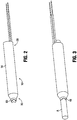
- the lead extracting device is designated generally by reference numeral 10 and includes an outer housing or body 14 and an internal tubular member or inner body 12 having a lumen dimensioned to receive a lead therein.
- the outer housing (outer tube) 14 has a proximal end 20 and a distal end 30.
- proximal refers to the portion that is closer to the user and the term “distal” refers to the portion that is further from the user.
- a cutting knife (cutter) or cutting portion 50 is positioned at the distal end 30 of outer housing 14 configured to cut tissue surrounding the lead, designated by reference letter "A".
- Figure 1 illustrates an anatomical view of the heart, illustrating the location of the cardiac lead A which is desired to be removed from the right ventricle B. It should be appreciated that the devices disclosed herein are described for removing a cardiac lead, however, it should be understood that the device also has other surgical applications. Note tissue ingrowth around the lead also occurs at regions along the length of the lead proximal of the distal tip of the lead.
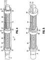
- the lead extractor includes a distal clamping ring 22, a proximal clamping ring 24, a distal fixed ring 26 and a proximal fixed ring 28.
- a first actuator or actuating (movement) mechanism in the form of a first wire or cable 32 is operably connected to the distal clamping ring 22 and a second actuator or actuating mechanism in the form of a second wire or cable 34 is operably connected to the proximal clamp ring 24.
- the cable 32 is operable to pivot distal clamping ring 22 from a substantially perpendicular position to an angled position with respect to the longitudinal axis of the extractor 10. In the substantially perpendicular position, the extracting device 10 is freely movable over the lead A.
- the distal clamping ring 22 frictionally engages, i.e., clamps, the external surface of the lead A as the surface around the opening in the clamping ring 22 frictionally engages the outer surface of the lead.
- clamping allows relative movement of the lead, i.e., "swallowing" of the lead described in detail below.
- the cable 34 is operable to pivot proximal clamp ring 24 from a substantially perpendicular position to an angled position with respect to the extractor 10. In the substantially perpendicular position, the extracting device 10 is freely movable over the lead A.
- proximal clamping ring 24 frictionally engages, i.e., clamps, the external surface of the lead A as the surface around the opening in the clamping ring 24 frictionally engages the outer surface of the lead.
- clamping allows relative movement of the lead, i.e., "swallowing" of the lead as described in detail below.
- a distal spring 36 is positioned around tubular member 12 to bias the distal clamp ring 22 in a distal direction and a proximal spring 38 is positioned around tubular member 12 to bias the proximal clamp ring 24 in the distal direction.
- First cable 32 also referred to herein as the distal ring cable, is fixedly attached to distal ring 22 (at connection 33), extends through an aperture 42 in the distal fixed ring 26 and an aperture 44 in proximal fixed ring 28.
- Proximal clamp ring 24 has a cutout or notch 27 to accommodate the first cable 32 (see also Figure 10 ).
- the cable 32 extends proximally to a position outside the patient for manipulation manually by a user or alternatively for connection to a motor as described below.
- Cable 34 also referred to herein as the proximal ring cable, is fixedly attached to proximal ring 24 (at connection 35) and extends through an aperture 46 in the proximal fixed ring 26.
- the cable 34 extends proximally to a position outside the patient for manipulation manually by a user or alternatively for connection to a motor.
- the cables 32 and 34 thereby provide a movement mechanism for the clamping members.
- the extractor 10 preferably has three operable positions.
- a first or initial position referred to as the neutral or zero position
- both the distal and proximal clamping rings 22, 24 are in the substantially perpendicular position in which they do not frictionally retain the cardiac lead and therefore the device 10 can be slidably moved over the lead A, as the lead A extends through the lumen of the tubular member 12.
- this sliding movement is obtained since the inside diameter of the opening in the distal ring and the inside diameter of the opening in the proximal ring 22 is greater, e.g., slightly greater, than the outside diameter D of the lead A.
- this neutral position also enables the device 10 at any time during the procedure to release the lead and be adjusted or removed from the lead and patient.
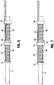
- the distal ring 22 is moved to the angled position to engage (clamp) the lead A while the proximal ring 24 remains in the substantially perpendicular position, as shown in Figure 6 .
- the proximal ring 24 is moved to the angled position to engage (clamp) the lead A while the distal ring 22 remains in the substantially perpendicular position, as shown in Figure 7 .
- the second position can denote when the proximal ring 22 is moved to the angled position to engage the lead A and the distal ring 24 remains in the substantially perpendicular position
- the third position would denote the position wherein the distal ring 22 is moved to the angled position to engage the lead A while the proximal ring 24 remains in the substantially perpendicular position.
- the knife (cutter) 50 preferably has an angled cutting edge that avoids the knife cutting into the vessel wall.
- the cutting edge is beveled at end 52, and has a small cutting edge 54 ( Figure 8 ), extending at an opposite angle to the bevel, thereby preventing the knife 50 from going into the lead.
- the knife 50 has a circular design with a sinuous shape, thereby providing a curved knife to perform a relative movement from the cutting edge to the tissue as in a guillotine-like action.
- the angles shown in Figure 8 are by way of example as other angles are also contemplated.
- the inner diameter E of the knife 50 ( Figure 9 ) preferably is slightly greater than the outer diameter of the lead A to be received in the lumen of device 10.
- the device 10 is inserted over the lead A and advanced over the lead A until the knife 50 at the distal end 30 of the tubular member 12 is at the desired site, namely the site where the lead A is embedded or surrounded by tissue so it cannot be removed. This is typically proximal of the distal tip of the lead. In this position, the device 10 is ready for lead extraction.
- the distal clamping ring 22 is pivoted to its angled position of Figure 12B to frictionally clamp or grasp the lead A.
- the lead A is pulled back due to its frictional engagement with the device 10 via distal clamp ring 22 as shown in Figure 12C and/or the device 10 is moved over the lead in this relative movement to "swallow" the lead A. (Since the proximal ring 24 is in its substantially perpendicular or non-engaging position, the lead can move through the opening in the ring 24).
- distal clamping ring 22 is pulled back a maximum of approximately halfway to the distal fixed ring 26.
- the distance between distal clamping ring 22 and distal fixed ring 26 is about 20 mm and the distal clamping ring 22 is pulled proximally about 10mm thereby moving the lead A proximally about 10 mm in the direction of the arrow of Figure 12C .
- Other distances are also contemplated.
- the second cable 34 can now be actuated.
- the user pulls cable 34 proximally, or if motor operated, the motor automatically pulls the cable 34 proximally after the first cable 32 has been pulled.
- the proximal clamping ring 24 is pivoted to its angled position of Figure 12D to frictionally clamp or grasp the lead A.
- the tension on the first cable 34 is released so the distal ring 22 can return to its substantially perpendicular or non-engaged position, aided by the force of distal spring 36 ( Figure 12E ).
- the first cable 32 (and thus the distal clamp ring 22) is not released until the second cable 34 has been tensioned to move the proximal ring 24 to engage the lead A. This helps prevent slippage, e.g., distal movement of the lead A, since the lead A is continuously being grasped, albeit by alternating the grasping function between the proximal and distal clamping rings 22, 24.
- proximal clamping ring 24 After the cable 34 has been pulled to pivot the proximal clamping ring 24 to its angled position, further retraction of the cable 34 pulls the lead A back (proximally) or moves the device 10 distally due to its frictional engagement with the device 10 via distal clamp ring 24. Thus, the lead A is relatively moved further back proximally in the direction of the arrow to further free it from surrounding tissue as the tissue is cut by knife 50 as shown in Figure 12F . As the proximal ring 22 is pulled proximally (rearwardly), it compresses proximal spring 38. In an exemplary embodiment, proximal ring 22 is pulled back a maximum of approximately halfway to the proximal fixed ring 28.
- the distance between proximal clamp ring 24 and proximal fixed ring 28 is about 20 mm and the proximal clamp ring 24 is pulled proximally about 10mm, thereby relatively moving the lead A about 10 mm.
- Other distances are also contemplated.
- the first cable 32 is pulled to once again pivot the distal ring 22 to the angled engaging position.
- the second cable 34 can now be released, followed by further retraction of the first cable 32, to move the lead proximally due to its frictional engagement.
- the second cable 34 is pulled proximally, followed by release of the first cable 34, and then further pulling of the cable 34 to move the lead A still further proximally and to continuously sever the surrounding tissue by knife 50.
- This step of alternatively pulling of the cables 32, 34 is repeated until the lead A is freed from the tissue and can be removed (with or separately from the device 10) from the tissue.
- This alternating cable motion can also be referred to as an oscillating movement in that the pulling of the cable alternates between the first and second cables, to incrementally pull the lead proximally or advance the extractor distally.
- This alternating action can also be considered as a step by step progressive "swallowing" of the lead. It can also be considered a tunneling action as it tunnels through tissue to separate tissue from the lead.
- Figures 13A-13D illustrate how the lead is pulled back relative to tissue T.
- Figure 13A shows the lead extractor being inserted over lead A to the position where the lead is captured by tissue T.
- the first cable 32 is pulled rearwardly and the lead A is retracted or the device 10 advanced as described above, with the tissue T engaging the cutting edge of knife 50 to cut the tissue surrounding the lead A to thereby free the lead (see Figure 13B ).
- the proximal clamp ring 24 is angled by the pulling of the second cable 34.
- the first cable 32 is then released, and the proximal cable 34 is pulled back further to further move the lead proximally or advance the device 10, thereby causing the tissue to again be into contact with the knife 50 to cut the tissue. As explained herein, this keeps being repeated so that the knife 50 can continue to cut the tissue as the lead A is incrementally and progressively pulled rearwardly or swallowed within the lumen of tube 12 of the lead extractor 10.
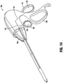
- this alternating movement can be achieved by handle mechanism 80 shown in Figure 14 .
- the handle mechanism 80 includes a first actuator 82, illustratively in the form of a pivotable handle with a finger loop 83, and a second actuator 84, also illustratively in the form of a pivotable handle with a finger loop 85.
- the first actuator 82 is operatively connected to the first cable 32 such that proximal movement of the actuator 82, e.g., moving of the finger loop 83 toward stationary handle 86, pulls the cable 32 proximally and distal movement returns the cable 32 to its original position.
- second actuator 84 is operatively connected to the second cable 34 such that proximal movement of the actuator 84 (away from the stationary handle 86) pulls the cable 34 proximally and distal movement returns the cable 34 to its original position.
- the handle mechanism 80 in a preferred embodiment includes a locking mechanism (not shown) to ensure that either cable 32, 34 cannot be released until the other cable has been moved proximally to move its respective clamping ring to the angled clamping position to frictionally engage the lead.
- a rotation knob 88 can be provided to rotate the lead extractor to thereby rotate the clamped lead if desired.
- the pistol grip and pivotable handles are shown by way of example as other handle configurations and other types of actuators, e.g., sliding tabs, are also contemplated to provide manual control of the cable movement.
- an external power source such as a motor assembly is provided to electrically drive (actuate) the cables instead of the manual operation by the user.
- motor rotation of the wheel 90 which is preferably eccentric, from the neutral position of Figure 11A to the position of Figure 11B , pulls cable 32 proximally to move the distal clamping ring 22 to the angled position and then to pull the distal clamping ring 22 proximally to retract or swallow the clamped lead as described above.
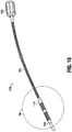
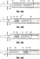
- FIGS 15-18 illustrate an alternate embodiment of the lead extractor, designated generally by reference numeral 100.
- the lead extractor 100 is identical to the lead extractor 10 of Figure 2 except for provision of the flexible tube/sheath. Therefore, the identical components have been labeled with corresponding numbers in the "100 series" so that extractor 100 has a knife (cutter) 150, distal clamping ring 122, a proximal clamping ring 124, a distal fixed ring 126, a proximal fixed ring 128, a first cable 132 operably connected to the distal clamp ring 122 and a second cable 134 operably connected to the proximal clamp ring 124.
- the cable 132 is operable to pivot distal clamping ring 122 from a substantially perpendicular position to an angled position and the cable 134 is operable to pivot proximal clamping ring 124 from a substantially perpendicular position to an angled position.
- a distal spring 136 is positioned around tubular member 112 to bias the distal clamping ring 122 in a distal direction and a proximal spring 138 is positioned around tubular member 112 to bias the proximal clamping ring 34 in the distal direction.
- the extractor 100 differs from extractor 10 in that a flexible tube (sheath) 160 having a handle 162 is provided.
- the handle 162 enables the extractor 100 to be rotated to thereby rotate the clamped lead. Such rotation provides an unscrewing action of the lead if the user deems it desirable.
- the tube 160 has a plurality of cutouts in the wall to provide the desired flexibility.
- the housing 114 can also have a plurality of cutouts in the wall to provide the desired flexibility.
- a sheath 170 is provided to cover the flexible tube 160.
- Figures 18A-18D illustrate the use of extractor 100 which is identical to the use described in conjunction with Figures 13A-13D except for provision of a flexible sheath 170 in which the housing 114 is positioned.
- the movement of the clamping rings 122 and 124, and relative movement of the extractor 10 and the lead A shown in Figures 18A-18D are identical to that of Figures 13A-13D and for brevity are not repeated herein.
- clamping rings Although two clamping rings are described in the embodiments herein, it is also contemplated that a single clamping ring or more than one clamping ring can be utilized.
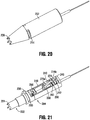
- the lead extractor is designated generally by reference numeral 200 and includes an outer body (outer housing) 202 and an inner body (inner housing) 204.
- the lead extractor 200 is similar to lead extractor 10 described above in that it is configured to move relative to the lead to "swallow" the lead in increments.
- the user manipulates the actuators to selectively control pivoting of the clamping members, alternately clamping and releasing the distal and proximal clamping members.
- the changed orientation of the clamping members is a result of the relative movement of the lead extractor 200 and lead.
- the lead extractor 200 has an enhanced cutting action as the cutter also rotates. Other differences between extractor 200 and extractor 10 will become apparent from the detailed description below of extractor 200.
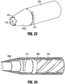
- outer body (or outer tube) 202 of lead extractor 200 has a proximal portion 206, a distal portion 208 and an intermediate portion 207 therebetween.
- a cutter or cutting portion 210 is formed at the distal portion 208 and preferably includes a serrated edge or toothed edge to effectively cut tissue adjacent the lead.
- Outer body 202 is positioned coaxially over inner housing (or inner tube) 204 as the inner housing 204 is received in lumen 216 of outer body 202.
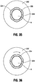
- Outer body 202 has an internal helical slot 218 and is rotatable relative to inner housing 204 (see Figures 35 and 36 ) to cut (sever and/or dissect) tissue as described in more detail below.
- Outer housing 202 has a conical tip 202a tapering in a distal direction to facilitate tunneling of the device.
- Radial slots 212, 214 receive disc 231 and another disc (not shown) or bars which are welded to the outer tube 202 to keep the device 200 together. Also, these block axial movement of the outer body 202 so that when the carrier 240 moves axially, since axial movement of the outer body 202 is blocked, it is forced to rotate.
- the inner housing 204 has a proximal portion 220, a distal portion 222 and an intermediate portion 226 between the proximal portion 220 and distal portion 222.
- a cutter or cutting portion 224 preferably having a serrated or toothed edge as shown, interacts with the cutting portion 210 of outer housing 202 to sever tissue adjacent the lead. That is, the cutting portion 210 of outer housing 202 overlies a counterpart cutting portion 224 of inner housing 204.
- a circumferential slot 230 is formed between ring 234 and distal end 232 of the carrier receiving portion to receive semicircular disc 231.
- Inner housing 204 has a pair of proximally extending arms 238 to form a gap to slidably receive carrier or vehicle 240. Movement of carrier 240 effects relative movement of the extractor 200 and lead. A proximal end cap 249 is secured within top and bottom notches 238a of arms 238 to secure the arms 238 and provide a back wall enclosure for the inner housing 204.
- Carrier 240 is slidably mounted within inner housing 204 for movement between proximal (retracted) and distal positions, proximal defined as noted above as the region closer to the user and distal as the region further from the user (and closer to the tip of the lead). The movement of carrier 240 provides the desired clamping of the lead which is positioned within the lumen 228 of inner housing 204. A cable 330 described in detail below effects movement of the carrier 240.
- Carrier 240 is formed by proximal fixed support ring 242, distal fixed support ring 250, upper support 274 and lower support 280.
- the terms “upper” and “lower” as used herein refer to the orientation of the device in the orientation shown in the drawings and are used herein for ease of description. Clearly, if the orientation of the device changes, the references “upper” and “lower” will also accordingly change.
- Contained within carrier 240 is proximal clamping ring 260 which has a hinge point on its lower surface and is biased by proximal spring 266 to a tilted position (with respect to the longitudinal axis of the extractor 200 and lead) as shown in Figures 21 and 25 .
- the proximal clamping ring 260 provides a clamping force on the lead as its central opening 264 is sufficiently angled with respect to the outer surface of the lead so the surface surrounding opening 264 grasps (clamps) the lead.
- Upper support 274 has a distal notch 278a seated within upper notch 252 of distal fixed support ring 250 and a proximal notch 278b seated within upper notch 244 of proximal fixed support ring 242 to retain and secure these components.
- lower support 280 has a distal notch 284a seated within lower notch 254 of distal fixed support ring 250 and a proximal notch 284b seated within lower notch 246 of proximal fixed support ring 242 to retain and secure these components.
- Upper tabs 276a, 276b of upper support 274 and lower tabs 282a, 282b of lower support 280 interact with the helical slot 218 formed in the outer housing 202 described in more detail below.
- Proximal clamping ring 260 receives elongated portion 274a of upper support 274 in upper slot 262.
- a similar slot on the opposing (bottom) side of proximal clamping ring 260 receives lower support 280.
- a slot 268 of proximal spring 266 accommodates upper support 274.
- Spring 266 is hinged at a bottom portion and has an opening 270 through which the lead can extend. Spring 266 is preferably attached to proximal clamping ring 260.
- distal clamping ring 290 Distal of carrier 240, positioned within inner housing 202 between arms 238, is a distal clamping ring 290 which has a hinge point on the top surface and is biased by distal spring 302 to the tilted position as shown in Figures 21 and 25 .
- Spring 302 is preferably attached to distal clamping ring 290 and hinged at a top portion.
- the distal clamping ring 290 and proximal clamping ring 260 have hinge points on opposing sides of the longitudinal axis of the device 10.
- the distal clamping ring opening 290 is at a sufficient angle with respect to the lead such that the lead is clamped by the ring 290.
- a ridged, toothed or irregular surface 295 is formed around part or alternatively the entire circumference of opening 292 in distal clamping ring 290 to enhance clamping of the lead extending therethrough when the distal clamping ring 290 is in the tilted position.
- Such ridged, toothed or irregular surface can also be provided around part or the entire circumference of the opening 264 of proximal clamping ring 260 to enhance clamping of the lead.
- Clamp engaging member 308 has a distal tab 314 and proximal tab 312.
- Clamp engaging member 310 similarly has a distal tab 320 and a proximal tab 318.
- the clamp engaging members 308, 310 are seated within side notches 294, 296, respectively, of distal clamping ring 290.
- the tabs 314, 312, 318, and 320 support and retain the upper end of the distal clamping ring 290.
- Cable 330 ( Figure 25 ) includes an outer cable 331 which is attached to the end cap 249 of inner housing 204. Coaxially positioned within the outer cable 331 is inner cable 333 which extends distally from outer cable 331 and is attached to the fixed proximal ring 242 of carrier 240. Cable 333 provides a movement mechanism as proximal movement of inner cable 333 pulls the carrier 240 in a proximal direction and distal movement of the inner cable 333 pushes the carrier 240 in a distal direction. The cable 333 is actuated by a trigger 340 shown in Figure 41 and described in conjunction with the method of use.
- the extractor 200 functions to extract the lead by application of the force at the distal end. That is, the lead extractor 200 is advanced in steps (increments) relative to the lead, thereby cutting e.g., severing and/or dissecting, tissue about the lead and tunneling around the lead to cut it away from tissue. When the tissue has been cut away, the lead can be extracted from the heart tissue.
- the extractor 200 and lead A are relatively movable with respect to each other.
- the extractor 200 will move progressively (in discrete increments) over the lead; if the lead is not fixed, then the extractor will progressively pull the lead (in discrete increments) back into the extractor 200.
- both the extractor and lead can move in opposing directions. In any event, this relative movement causes the "swallowing" of the lead by the extractor 200.
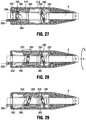
- Figures 25-29 show in cross-sectional views operation of the extractor 200.
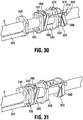
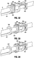
- Figures 30-34 are perspective views corresponding to the respective positions of Figures 24-29 , however the inner housing 204 and outer housing 202 have been removed for clarity.
- the device 200 is inserted over a proximal end of the lead, e.g., a cardiac lead, which is embedded in tissue and desired to be removed.
- the extractor 200 is advanced until the distal end 208 of the outer housing 202 encounters hard tissue. Note, in the insertion position, the proximal clamping ring 260 is tilted toward the distal end and the distal clamping ring 290 is tilted toward the proximal end as shown in Figures 25 and 30 .
- the extractor 200 can be forced over the lead A with the openings 292 and 264 of distal and proximal clamping rings 290, 260 providing a sufficient gap (upon such force being applied) for passage of the outer diameter of the lead and not providing a sufficient clamping or frictional force on the lead A to prevent such passage.
- springs 266 and 302 are not compressed and bias the clamping rings 260, 290, respectively in the tilted positions shown.
- the clamping rings 260, 290 can optionally be moved to a less tilted position by movement to the override position described below for initial insertion of the lead, however, in this embodiment it is not necessary since the extractor 200 can be forced over the lead.
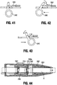
- the user actuates trigger 340 ( Figure 42 ) to thereby pull inner cable 333 proximally, which pulls the carrier 240 proximally since cable 331 is attached to the fixed proximal ring 242.
- trigger 340 Figure 42
- the extractor 200 is advanced distally over the lead A as proximal clamping ring 260 clamps lead A. Note the more relative movement of carrier 240 and lead A, the more tilting of the proximal clamping ring 260 and more clamping force applied to the lead A.
- the outer housing 202 rotates, preferably about 45 degrees although other degrees of rotation are also contemplated, due to the engagement of tabs 276a, 276b (of upper support 274) and the engagement of tabs 282a, 282b (of lower support 280) with the internal helical slot 218 of outer housing 202.
- This axial and rotational movement of outer housing 202, in cooperation with the stationary (non-rotating) cutting portion 224 of inner housing 204, facilitates the cutting portions cutting through tissue around the lead A.
- This retracted position of carrier 240 is also shown in Figure 31 .
- distal clamp ring 290 is pivoted about upper hinge point in a clockwise direction, compressing spring 302.
- the relative movement of the extractor 200 and lead A causes the distal clamping ring 290 to move to this less angled position of Figure 26 to facilitate movement of the extractor 200 as the opening in the distal clamping ring 290 provides a larger diameter with respect to the outer diameter of the lead A and no longer provides a restrictive clamping force on the lead A.
- the angle of the proximal clamping member 260 might not substantially change during such retraction of carrier 240, remaining in substantially the same position as in Figure 25 , biased by spring 266, it will tilt more if needed such as if a larger force is applied.
- the trigger 340 is returned to the neutral position ( Figure 41 ), thereby pushing cable 331 distally, which pushes the carrier 240 distally in the direction of the arrow of Figure 27 to reset the extractor 200 for the next incremental movement.
- the interaction with the lead A pivots the proximal clamping ring 260 about its bottom hinge in a counterclockwise direction to a more vertical position, thereby compressing spring 266, and creating a larger diameter gap about opening 264 with respect to the outer diameter of the lead A to facilitate movement of the extractor 200 with respect to the lead A.
- the carrier 240 thereby moves to the distal position of Figures 28 and 33 , with proximal clamping ring 260 remaining in the less tilted (and unclamped) position as a result of such movement.
- Distal clamping member 290 returns to the tilted position of Figure 25 as the extractor 200 is moved relative to lead A and it remains in the tilted clamping position to clamp the lead A and prevent the lead shifting back, i.e., reversing itself.
- Such distal movement of carrier 240 causes the outer housing 202 to rotate during its axial advancement due to the tab/helical slot 218 engagement discussed above, the axial movement and rotation of the cutter (rotating relative to the fixed cutting portion of inner housing 204) cutting tissue around the lead A.
- clamping member 290 prevents the lead from moving back and there is no (or little) relative movement of the lead and extractor 200. However, the outer housing 202 will still rotate upon movement of the carrier 240, thus making the same but opposite cutting movement when the carrier 240 is moved distally.
- proximal clamping ring 260 when the carrier 240 is moved proximally to swallow the lead A, proximal clamping ring 260 remains in the same angular position (although it is moved axially) and distal clamping ring 290 is rotated by the lead to a less angled position; and when the carrier 240 is moved distally to reset, the distal clamping ring 290 returns, due to the lead (and assisted by spring 302), to the tilted (angular) position to prevent reverse relative movement with the lead and the proximal clamping ring 260 is tilted by the lead A to a less angled (move vertical) position.
- Such rotation or tilting of proximal clamping ring 260 compresses the biasing spring 266.
- proximal and distal clamping rings 260, 290 do not perform a clamping function when they are not sufficiently tilted, i.e., when they are in a substantially vertical position.
- the springs 266, 302 aid the clamping rings 260, 290 in making the initial tilting to a more angled position.
- the tilting increases and the locking force increases. The greater the force, the better the locking on the lead.
- the trigger or actuator 340 is repeatedly pulled and released, to cause progressive and incremental relative movement of the extractor 200 and lead A to cut, e.g., sever and/or dissect, tissue adjacent the lead and "swallow" the lead A to free the lead from the surrounding tissue so it can be removed from the body.
- this movement and tunneling action of the extractor 200 results in the removal force applied at the distal end of the device, adjacent the tissue engagement of the lead.
- the trigger 340 is moved to its forwardmost (distalmost) position to move the carrier 240 to an advanced override position.
- This override position is distal of the carrier position of Figures 25 and 30 .
- the carrier 240 is advanced so the distal edge 275 of upper support 274 contacts a proximal end 290a of distal clamping ring 290 forcing it to a less tilted position, and in some embodiments a positon close to about 90 degrees with respect to the longitudinal axis of the lead A.
- Such movement of the carrier 240 with respect to the lead A also causes the proximal clamping ring 260 to move to the less tilted position as it does in Figures 27 and 28 .
- the extractor 200 can more freely slide over the lead A and be removed from the patient's body.
- a detent can be provided to limit movement of the trigger to the position of Figure 41 , and then overridden by application of sufficient force to move the trigger to the override position.
- a latch or other locking mechanism can be provided to restrict movement of the trigger to the position of Figure 41 , and released to allow movement of trigger 340 to the position of Figure 43 to cancel the procedure.
- a retention mechanism can be provided to retain the trigger in the override position.
- the trigger 340 can be in the neutral position of Figure 41 and then return to the position of Figure 41 when released from the position of Figure 42 .
- the trigger mechanism can include a stop such as a detent, which would prevent movement of the trigger 340 to the override position of Figure 43 during its normal use, and require sufficient force of the trigger 340 to override the detent to force it into the override position of Figure 43 .
- an external power source such as a motor can be provided to electrically drive (actuate) the cable 333 instead of manual operation by the user.
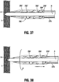
- a flexible sheath 370 is provided which enables unscrewing of the lead at the distal end.
- the sheath 370 also has sufficient rigidity to allow for rotation.
- the lead extractor 200' is the same as lead extractor 200 except for the provision of the sheath positioned over a portion of the extractor 200'.
- the extractor 200' is used in the identical fashion as extractor 200 described above to separate the lead from the tissue encapsulating the lead along its length.
- the components of the extractor 200' and their function will not be repeated herein as they are identical to extractor 200, and identical components, e.g., outer housing 202', distal clamping ring 290', and proximal clamping ring 260' are labeled with "prime” designations.
- the sheath 370 is attached to the proximal end cap 249' of the inner tube 204' and extends proximally of the end cap 249', forming an extension of the inner tube 204'.
- the flexible sheath 370 is rotated ( Figure 38 ), which in turn rotates the extractor 200'. Since the lead A is firmly clamped by the extractor 200', rotation of the sheath 370 also rotates the lead A, thereby unscrewing the distal tip B of the lead A which is embedded in tissue ( Figure 39 ). The sheath 370, extractor 200' and clamped lead A can then be removed from the body as shown in Figure 40 .
- the extractors of the present disclosure can also be utilized in other surgical applications.
Landscapes
- Health & Medical Sciences (AREA)
- Life Sciences & Earth Sciences (AREA)
- Surgery (AREA)
- Heart & Thoracic Surgery (AREA)
- Veterinary Medicine (AREA)
- Public Health (AREA)
- Engineering & Computer Science (AREA)
- Nuclear Medicine, Radiotherapy & Molecular Imaging (AREA)
- Biomedical Technology (AREA)
- Animal Behavior & Ethology (AREA)
- General Health & Medical Sciences (AREA)
- Molecular Biology (AREA)
- Medical Informatics (AREA)
- Pathology (AREA)
- Vascular Medicine (AREA)
- Cardiology (AREA)
- Radiology & Medical Imaging (AREA)
- Electrotherapy Devices (AREA)
- Surgical Instruments (AREA)
Applications Claiming Priority (3)
| Application Number | Priority Date | Filing Date | Title |
|---|---|---|---|
| US201361869729P | 2013-08-25 | 2013-08-25 | |
| US14/455,921 US9889294B2 (en) | 2013-08-25 | 2014-08-10 | Extractor for removing a lead from a patient |
| PCT/IB2014/001916 WO2015028882A1 (en) | 2013-08-25 | 2014-08-17 | Extractor for removing a lead from a patient |
Publications (2)
| Publication Number | Publication Date |
|---|---|
| EP3038550A1 EP3038550A1 (en) | 2016-07-06 |
| EP3038550B1 true EP3038550B1 (en) | 2019-06-12 |
Family
ID=52481027
Family Applications (1)
| Application Number | Title | Priority Date | Filing Date |
|---|---|---|---|
| EP14789367.1A Active EP3038550B1 (en) | 2013-08-25 | 2014-08-17 | Extractor for removing a lead from a patient |
Country Status (5)
| Country | Link |
|---|---|
| US (3) | US9889294B2 (enExample) |
| EP (1) | EP3038550B1 (enExample) |
| JP (1) | JP2016531691A (enExample) |
| ES (1) | ES2744394T3 (enExample) |
| WO (1) | WO2015028882A1 (enExample) |
Families Citing this family (17)
| Publication number | Priority date | Publication date | Assignee | Title |
|---|---|---|---|---|
| US9072897B2 (en) | 2007-03-09 | 2015-07-07 | Mainstay Medical Limited | Systems and methods for restoring muscle function to the lumbar spine |
| US11679261B2 (en) | 2007-03-09 | 2023-06-20 | Mainstay Medical Limited | Systems and methods for enhancing function of spine stabilization muscles associated with a spine surgery intervention |
| US11679262B2 (en) | 2007-03-09 | 2023-06-20 | Mainstay Medical Limited | Systems and methods for restoring muscle function to the lumbar spine |
| US11786725B2 (en) | 2012-06-13 | 2023-10-17 | Mainstay Medical Limited | Systems and methods for restoring muscle function to the lumbar spine and kits for implanting the same |
| WO2011112773A2 (en) | 2010-03-11 | 2011-09-15 | Mainstay Medical, Inc. | Modular stimulator for treatment of back pain, implantable rf ablation system and methods of use |
| US12097365B2 (en) | 2010-03-11 | 2024-09-24 | Mainstay Medical Limited | Electrical stimulator for the treatment of back pain and methods of use |
| US12594096B2 (en) | 2012-06-13 | 2026-04-07 | Mainstay Medical Limited | Systems and methods for enhanced implantation of electrode leads between tissue layers |
| US10207105B2 (en) | 2013-08-25 | 2019-02-19 | Talpanetics bv | Extractor for removing a lead from a patient |
| US9889294B2 (en) * | 2013-08-25 | 2018-02-13 | Talpanetics bv | Extractor for removing a lead from a patient |
| EP3337413B1 (en) * | 2015-08-17 | 2020-09-30 | Talpanetics B.V. | Extractor for removing a lead from a patient |
| WO2017173146A1 (en) * | 2016-03-31 | 2017-10-05 | Cardiac Pacemakers, Inc. | Chronically implantable medical devices configured for extraction and extraction devices for extracting chronically implanted medical devices |
| EP3436137B1 (en) * | 2016-03-31 | 2021-12-15 | Cardiac Pacemakers, Inc. | Extraction devices configued to extract chronically implanted medical devices |
| WO2019038773A1 (en) | 2017-08-25 | 2019-02-28 | Mdsg Innovation Ltd. | CARDIAC PROBE EXTRACTION DEVICE |
| US11678908B2 (en) | 2019-09-06 | 2023-06-20 | Koninklijke Philips N.V. | Traction applying devices for lead removal systems |
| IL283558B2 (en) * | 2021-05-30 | 2023-03-01 | Xtrac O S Ltd | Coil stop device |
| EP4124309B1 (en) | 2021-07-29 | 2025-04-30 | Merit Medical Systems, Inc. | Medical devices that include a trigger assembly for a rotatable catheter |
| US12582816B2 (en) | 2022-03-22 | 2026-03-24 | Mainstay Medical Limited | Systems and methods for extracting an electrode lead |
Family Cites Families (18)
| Publication number | Priority date | Publication date | Assignee | Title |
|---|---|---|---|---|
| US4576162A (en) * | 1983-03-30 | 1986-03-18 | Mccorkle Charles E | Apparatus and method for separation of scar tissue in venous pathway |
| US4582056A (en) * | 1983-03-30 | 1986-04-15 | Mccorkle Jr Charles E | Endocardial lead extraction apparatus and method |
| US4574800A (en) | 1984-12-07 | 1986-03-11 | Cordis Corporation | Implanted lead extractor |
| US6033402A (en) | 1998-09-28 | 2000-03-07 | Irvine Biomedical, Inc. | Ablation device for lead extraction and methods thereof |
| US20030092995A1 (en) * | 2001-11-13 | 2003-05-15 | Medtronic, Inc. | System and method of positioning implantable medical devices |
| EP1618920A3 (en) | 2002-12-16 | 2007-05-30 | Meagan Medical, Inc. | Controlling the depth of percuataneous applications |
| US8092467B1 (en) | 2005-10-28 | 2012-01-10 | Curtis Charles Lindstrom | Apparatus and method facilitating removal of a structure implanted in a body |
| EP1935348B1 (en) | 2006-12-22 | 2013-09-04 | The Spectranetics Corporation | Tissue separating systems |
| US8961551B2 (en) | 2006-12-22 | 2015-02-24 | The Spectranetics Corporation | Retractable separating systems and methods |
| EP2384153B1 (en) | 2009-01-13 | 2015-06-03 | Leadex Cardiac Ltd. | Lead extraction apparatus |
| US20110106099A1 (en) | 2009-10-29 | 2011-05-05 | Medtronic, Inc. | Lead extraction device |
| EP2525864A4 (en) | 2010-01-20 | 2014-03-05 | Pavilion Medical Innovations Llc | SYSTEMS AND METHODS FOR REMOVING INTRAVASCULAR PROBES |
| WO2012131492A1 (en) | 2011-04-01 | 2012-10-04 | Leadex Cardiac Ltd. | Lead extraction methods and apparatus |
| US9649490B2 (en) * | 2011-06-16 | 2017-05-16 | Cook Medical Technologies Llc | Tip for lead extraction device |
| EP2589348B1 (de) * | 2011-11-03 | 2017-12-06 | VascoMed GmbH | Vorrichtung zur Explantation von Elektrodenleitungen |
| US10207105B2 (en) * | 2013-08-25 | 2019-02-19 | Talpanetics bv | Extractor for removing a lead from a patient |
| US9889294B2 (en) * | 2013-08-25 | 2018-02-13 | Talpanetics bv | Extractor for removing a lead from a patient |
| EP3720373B1 (en) * | 2017-12-04 | 2026-01-21 | Xtrac O.S Ltd | System for lead extraction |
-
2014
- 2014-08-10 US US14/455,921 patent/US9889294B2/en not_active Expired - Fee Related
- 2014-08-17 ES ES14789367T patent/ES2744394T3/es active Active
- 2014-08-17 JP JP2016537397A patent/JP2016531691A/ja active Pending
- 2014-08-17 EP EP14789367.1A patent/EP3038550B1/en active Active
- 2014-08-17 WO PCT/IB2014/001916 patent/WO2015028882A1/en not_active Ceased
-
2017
- 2017-07-20 US US15/655,773 patent/US10532207B2/en active Active
-
2019
- 2019-12-22 US US16/724,312 patent/US11648396B2/en active Active
Non-Patent Citations (1)
| Title |
|---|
| None * |
Also Published As
| Publication number | Publication date |
|---|---|
| US20170312495A1 (en) | 2017-11-02 |
| US20200121918A1 (en) | 2020-04-23 |
| US11648396B2 (en) | 2023-05-16 |
| US9889294B2 (en) | 2018-02-13 |
| US20150057672A1 (en) | 2015-02-26 |
| ES2744394T3 (es) | 2020-02-24 |
| EP3038550A1 (en) | 2016-07-06 |
| WO2015028882A1 (en) | 2015-03-05 |
| JP2016531691A (ja) | 2016-10-13 |
| US10532207B2 (en) | 2020-01-14 |
Similar Documents
| Publication | Publication Date | Title |
|---|---|---|
| US11648396B2 (en) | Extractor for removing a lead from a patient | |
| US20230015358A1 (en) | Extractor for removing a lead from a patient | |
| EP3638365B1 (en) | Implant delivery and retrieval systems and methods | |
| US10709488B2 (en) | Biceps tenodesis delivery tools | |
| KR101299084B1 (ko) | 리드추출장치 | |
| US20100222787A1 (en) | Tension control device | |
| US5549615A (en) | Method and apparatus for extracting pacemaker electrodes embedded in the heart | |
| CN104415452B (zh) | 用于抽取装置的增强外鞘管 | |
| CN108135636B (zh) | 导管摘出 | |
| US10828499B2 (en) | Implant delivery and retrieval systems and methods | |
| EP3337413B1 (en) | Extractor for removing a lead from a patient | |
| EP3958748B1 (en) | Non-penetrating tissue separator | |
| EP4635428A1 (en) | Ligation device capable of automatically cutting ligature wire | |
| CN120713607B (zh) | 一种从下腔静脉途径对心脏起搏电极的分段拔除装置 | |
| EP4324510B1 (en) | Biostimulator transport system having drive belt |
Legal Events
| Date | Code | Title | Description |
|---|---|---|---|
| PUAI | Public reference made under article 153(3) epc to a published international application that has entered the european phase |
Free format text: ORIGINAL CODE: 0009012 |
|
| 17P | Request for examination filed |
Effective date: 20160315 |
|
| AK | Designated contracting states |
Kind code of ref document: A1 Designated state(s): AL AT BE BG CH CY CZ DE DK EE ES FI FR GB GR HR HU IE IS IT LI LT LU LV MC MK MT NL NO PL PT RO RS SE SI SK SM TR |
|
| AX | Request for extension of the european patent |
Extension state: BA ME |
|
| DAX | Request for extension of the european patent (deleted) | ||
| GRAP | Despatch of communication of intention to grant a patent |
Free format text: ORIGINAL CODE: EPIDOSNIGR1 |
|
| STAA | Information on the status of an ep patent application or granted ep patent |
Free format text: STATUS: GRANT OF PATENT IS INTENDED |
|
| RIC1 | Information provided on ipc code assigned before grant |
Ipc: A61B 17/34 20060101AFI20181130BHEP |
|
| INTG | Intention to grant announced |
Effective date: 20190108 |
|
| GRAS | Grant fee paid |
Free format text: ORIGINAL CODE: EPIDOSNIGR3 |
|
| GRAA | (expected) grant |
Free format text: ORIGINAL CODE: 0009210 |
|
| STAA | Information on the status of an ep patent application or granted ep patent |
Free format text: STATUS: THE PATENT HAS BEEN GRANTED |
|
| AK | Designated contracting states |
Kind code of ref document: B1 Designated state(s): AL AT BE BG CH CY CZ DE DK EE ES FI FR GB GR HR HU IE IS IT LI LT LU LV MC MK MT NL NO PL PT RO RS SE SI SK SM TR |
|
| REG | Reference to a national code |
Ref country code: GB Ref legal event code: FG4D |
|
| REG | Reference to a national code |
Ref country code: CH Ref legal event code: EP |
|
| REG | Reference to a national code |
Ref country code: AT Ref legal event code: REF Ref document number: 1141564 Country of ref document: AT Kind code of ref document: T Effective date: 20190615 |
|
| REG | Reference to a national code |
Ref country code: DE Ref legal event code: R096 Ref document number: 602014048290 Country of ref document: DE |
|
| REG | Reference to a national code |
Ref country code: IE Ref legal event code: FG4D |
|
| REG | Reference to a national code |
Ref country code: NL Ref legal event code: MP Effective date: 20190612 |
|
| REG | Reference to a national code |
Ref country code: LT Ref legal event code: MG4D |
|
| PG25 | Lapsed in a contracting state [announced via postgrant information from national office to epo] |
Ref country code: FI Free format text: LAPSE BECAUSE OF FAILURE TO SUBMIT A TRANSLATION OF THE DESCRIPTION OR TO PAY THE FEE WITHIN THE PRESCRIBED TIME-LIMIT Effective date: 20190612 Ref country code: NO Free format text: LAPSE BECAUSE OF FAILURE TO SUBMIT A TRANSLATION OF THE DESCRIPTION OR TO PAY THE FEE WITHIN THE PRESCRIBED TIME-LIMIT Effective date: 20190912 Ref country code: AL Free format text: LAPSE BECAUSE OF FAILURE TO SUBMIT A TRANSLATION OF THE DESCRIPTION OR TO PAY THE FEE WITHIN THE PRESCRIBED TIME-LIMIT Effective date: 20190612 Ref country code: SE Free format text: LAPSE BECAUSE OF FAILURE TO SUBMIT A TRANSLATION OF THE DESCRIPTION OR TO PAY THE FEE WITHIN THE PRESCRIBED TIME-LIMIT Effective date: 20190612 Ref country code: LT Free format text: LAPSE BECAUSE OF FAILURE TO SUBMIT A TRANSLATION OF THE DESCRIPTION OR TO PAY THE FEE WITHIN THE PRESCRIBED TIME-LIMIT Effective date: 20190612 Ref country code: HR Free format text: LAPSE BECAUSE OF FAILURE TO SUBMIT A TRANSLATION OF THE DESCRIPTION OR TO PAY THE FEE WITHIN THE PRESCRIBED TIME-LIMIT Effective date: 20190612 |
|
| PGFP | Annual fee paid to national office [announced via postgrant information from national office to epo] |
Ref country code: ES Payment date: 20190902 Year of fee payment: 6 |
|
| PG25 | Lapsed in a contracting state [announced via postgrant information from national office to epo] |
Ref country code: GR Free format text: LAPSE BECAUSE OF FAILURE TO SUBMIT A TRANSLATION OF THE DESCRIPTION OR TO PAY THE FEE WITHIN THE PRESCRIBED TIME-LIMIT Effective date: 20190913 Ref country code: RS Free format text: LAPSE BECAUSE OF FAILURE TO SUBMIT A TRANSLATION OF THE DESCRIPTION OR TO PAY THE FEE WITHIN THE PRESCRIBED TIME-LIMIT Effective date: 20190612 Ref country code: BG Free format text: LAPSE BECAUSE OF FAILURE TO SUBMIT A TRANSLATION OF THE DESCRIPTION OR TO PAY THE FEE WITHIN THE PRESCRIBED TIME-LIMIT Effective date: 20190912 Ref country code: LV Free format text: LAPSE BECAUSE OF FAILURE TO SUBMIT A TRANSLATION OF THE DESCRIPTION OR TO PAY THE FEE WITHIN THE PRESCRIBED TIME-LIMIT Effective date: 20190612 |
|
| REG | Reference to a national code |
Ref country code: AT Ref legal event code: MK05 Ref document number: 1141564 Country of ref document: AT Kind code of ref document: T Effective date: 20190612 |
|
| PG25 | Lapsed in a contracting state [announced via postgrant information from national office to epo] |
Ref country code: RO Free format text: LAPSE BECAUSE OF FAILURE TO SUBMIT A TRANSLATION OF THE DESCRIPTION OR TO PAY THE FEE WITHIN THE PRESCRIBED TIME-LIMIT Effective date: 20190612 Ref country code: CZ Free format text: LAPSE BECAUSE OF FAILURE TO SUBMIT A TRANSLATION OF THE DESCRIPTION OR TO PAY THE FEE WITHIN THE PRESCRIBED TIME-LIMIT Effective date: 20190612 Ref country code: EE Free format text: LAPSE BECAUSE OF FAILURE TO SUBMIT A TRANSLATION OF THE DESCRIPTION OR TO PAY THE FEE WITHIN THE PRESCRIBED TIME-LIMIT Effective date: 20190612 Ref country code: NL Free format text: LAPSE BECAUSE OF FAILURE TO SUBMIT A TRANSLATION OF THE DESCRIPTION OR TO PAY THE FEE WITHIN THE PRESCRIBED TIME-LIMIT Effective date: 20190612 Ref country code: AT Free format text: LAPSE BECAUSE OF FAILURE TO SUBMIT A TRANSLATION OF THE DESCRIPTION OR TO PAY THE FEE WITHIN THE PRESCRIBED TIME-LIMIT Effective date: 20190612 Ref country code: PT Free format text: LAPSE BECAUSE OF FAILURE TO SUBMIT A TRANSLATION OF THE DESCRIPTION OR TO PAY THE FEE WITHIN THE PRESCRIBED TIME-LIMIT Effective date: 20191014 Ref country code: SK Free format text: LAPSE BECAUSE OF FAILURE TO SUBMIT A TRANSLATION OF THE DESCRIPTION OR TO PAY THE FEE WITHIN THE PRESCRIBED TIME-LIMIT Effective date: 20190612 |
|
| REG | Reference to a national code |
Ref country code: ES Ref legal event code: FG2A Ref document number: 2744394 Country of ref document: ES Kind code of ref document: T3 Effective date: 20200224 |
|
| PG25 | Lapsed in a contracting state [announced via postgrant information from national office to epo] |
Ref country code: SM Free format text: LAPSE BECAUSE OF FAILURE TO SUBMIT A TRANSLATION OF THE DESCRIPTION OR TO PAY THE FEE WITHIN THE PRESCRIBED TIME-LIMIT Effective date: 20190612 Ref country code: IS Free format text: LAPSE BECAUSE OF FAILURE TO SUBMIT A TRANSLATION OF THE DESCRIPTION OR TO PAY THE FEE WITHIN THE PRESCRIBED TIME-LIMIT Effective date: 20191012 |
|
| REG | Reference to a national code |
Ref country code: DE Ref legal event code: R097 Ref document number: 602014048290 Country of ref document: DE |
|
| PG25 | Lapsed in a contracting state [announced via postgrant information from national office to epo] |
Ref country code: TR Free format text: LAPSE BECAUSE OF FAILURE TO SUBMIT A TRANSLATION OF THE DESCRIPTION OR TO PAY THE FEE WITHIN THE PRESCRIBED TIME-LIMIT Effective date: 20190612 |
|
| PLBE | No opposition filed within time limit |
Free format text: ORIGINAL CODE: 0009261 |
|
| STAA | Information on the status of an ep patent application or granted ep patent |
Free format text: STATUS: NO OPPOSITION FILED WITHIN TIME LIMIT |
|
| PG25 | Lapsed in a contracting state [announced via postgrant information from national office to epo] |
Ref country code: DK Free format text: LAPSE BECAUSE OF FAILURE TO SUBMIT A TRANSLATION OF THE DESCRIPTION OR TO PAY THE FEE WITHIN THE PRESCRIBED TIME-LIMIT Effective date: 20190612 Ref country code: PL Free format text: LAPSE BECAUSE OF FAILURE TO SUBMIT A TRANSLATION OF THE DESCRIPTION OR TO PAY THE FEE WITHIN THE PRESCRIBED TIME-LIMIT Effective date: 20190612 |
|
| 26N | No opposition filed |
Effective date: 20200313 |
|
| PG25 | Lapsed in a contracting state [announced via postgrant information from national office to epo] |
Ref country code: SI Free format text: LAPSE BECAUSE OF FAILURE TO SUBMIT A TRANSLATION OF THE DESCRIPTION OR TO PAY THE FEE WITHIN THE PRESCRIBED TIME-LIMIT Effective date: 20190612 Ref country code: CH Free format text: LAPSE BECAUSE OF NON-PAYMENT OF DUE FEES Effective date: 20190831 Ref country code: LU Free format text: LAPSE BECAUSE OF NON-PAYMENT OF DUE FEES Effective date: 20190817 Ref country code: IS Free format text: LAPSE BECAUSE OF FAILURE TO SUBMIT A TRANSLATION OF THE DESCRIPTION OR TO PAY THE FEE WITHIN THE PRESCRIBED TIME-LIMIT Effective date: 20200224 Ref country code: MC Free format text: LAPSE BECAUSE OF FAILURE TO SUBMIT A TRANSLATION OF THE DESCRIPTION OR TO PAY THE FEE WITHIN THE PRESCRIBED TIME-LIMIT Effective date: 20190612 Ref country code: LI Free format text: LAPSE BECAUSE OF NON-PAYMENT OF DUE FEES Effective date: 20190831 |
|
| REG | Reference to a national code |
Ref country code: BE Ref legal event code: MM Effective date: 20190831 |
|
| PG2D | Information on lapse in contracting state deleted |
Ref country code: IS |
|
| PG25 | Lapsed in a contracting state [announced via postgrant information from national office to epo] |
Ref country code: IE Free format text: LAPSE BECAUSE OF NON-PAYMENT OF DUE FEES Effective date: 20190817 |
|
| PG25 | Lapsed in a contracting state [announced via postgrant information from national office to epo] |
Ref country code: BE Free format text: LAPSE BECAUSE OF NON-PAYMENT OF DUE FEES Effective date: 20190831 |
|
| PG25 | Lapsed in a contracting state [announced via postgrant information from national office to epo] |
Ref country code: CY Free format text: LAPSE BECAUSE OF FAILURE TO SUBMIT A TRANSLATION OF THE DESCRIPTION OR TO PAY THE FEE WITHIN THE PRESCRIBED TIME-LIMIT Effective date: 20190612 |
|
| PG25 | Lapsed in a contracting state [announced via postgrant information from national office to epo] |
Ref country code: MT Free format text: LAPSE BECAUSE OF FAILURE TO SUBMIT A TRANSLATION OF THE DESCRIPTION OR TO PAY THE FEE WITHIN THE PRESCRIBED TIME-LIMIT Effective date: 20190612 Ref country code: HU Free format text: LAPSE BECAUSE OF FAILURE TO SUBMIT A TRANSLATION OF THE DESCRIPTION OR TO PAY THE FEE WITHIN THE PRESCRIBED TIME-LIMIT; INVALID AB INITIO Effective date: 20140817 |
|
| REG | Reference to a national code |
Ref country code: ES Ref legal event code: FD2A Effective date: 20220110 |
|
| PG25 | Lapsed in a contracting state [announced via postgrant information from national office to epo] |
Ref country code: ES Free format text: LAPSE BECAUSE OF NON-PAYMENT OF DUE FEES Effective date: 20200818 |
|
| PG25 | Lapsed in a contracting state [announced via postgrant information from national office to epo] |
Ref country code: MK Free format text: LAPSE BECAUSE OF FAILURE TO SUBMIT A TRANSLATION OF THE DESCRIPTION OR TO PAY THE FEE WITHIN THE PRESCRIBED TIME-LIMIT Effective date: 20190612 |
|
| P01 | Opt-out of the competence of the unified patent court (upc) registered |
Effective date: 20230518 |
|
| PGFP | Annual fee paid to national office [announced via postgrant information from national office to epo] |
Ref country code: DE Payment date: 20240828 Year of fee payment: 11 |
|
| PGFP | Annual fee paid to national office [announced via postgrant information from national office to epo] |
Ref country code: GB Payment date: 20240827 Year of fee payment: 11 |
|
| PGFP | Annual fee paid to national office [announced via postgrant information from national office to epo] |
Ref country code: FR Payment date: 20240827 Year of fee payment: 11 |
|
| PGFP | Annual fee paid to national office [announced via postgrant information from national office to epo] |
Ref country code: IT Payment date: 20240827 Year of fee payment: 11 |
|
| REG | Reference to a national code |
Ref country code: DE Ref legal event code: R119 Ref document number: 602014048290 Country of ref document: DE |