EP3038233A1 - Permanent-magnet synchronous motor and electric power steering - Google Patents
Permanent-magnet synchronous motor and electric power steering Download PDFInfo
- Publication number
- EP3038233A1 EP3038233A1 EP15198633.8A EP15198633A EP3038233A1 EP 3038233 A1 EP3038233 A1 EP 3038233A1 EP 15198633 A EP15198633 A EP 15198633A EP 3038233 A1 EP3038233 A1 EP 3038233A1
- Authority
- EP
- European Patent Office
- Prior art keywords
- stator
- rotor
- synchronous motor
- permanent magnet
- magnet synchronous
- Prior art date
- Legal status (The legal status is an assumption and is not a legal conclusion. Google has not performed a legal analysis and makes no representation as to the accuracy of the status listed.)
- Granted
Links
Images


Classifications
-
- H—ELECTRICITY
- H02—GENERATION; CONVERSION OR DISTRIBUTION OF ELECTRIC POWER
- H02K—DYNAMO-ELECTRIC MACHINES
- H02K21/00—Synchronous motors having permanent magnets; Synchronous generators having permanent magnets
- H02K21/12—Synchronous motors having permanent magnets; Synchronous generators having permanent magnets with stationary armatures and rotating magnets
- H02K21/14—Synchronous motors having permanent magnets; Synchronous generators having permanent magnets with stationary armatures and rotating magnets with magnets rotating within the armatures
-
- H—ELECTRICITY
- H02—GENERATION; CONVERSION OR DISTRIBUTION OF ELECTRIC POWER
- H02K—DYNAMO-ELECTRIC MACHINES
- H02K21/00—Synchronous motors having permanent magnets; Synchronous generators having permanent magnets
- H02K21/12—Synchronous motors having permanent magnets; Synchronous generators having permanent magnets with stationary armatures and rotating magnets
-
- H—ELECTRICITY
- H02—GENERATION; CONVERSION OR DISTRIBUTION OF ELECTRIC POWER
- H02K—DYNAMO-ELECTRIC MACHINES
- H02K1/00—Details of the magnetic circuit
- H02K1/06—Details of the magnetic circuit characterised by the shape, form or construction
- H02K1/12—Stationary parts of the magnetic circuit
- H02K1/14—Stator cores with salient poles
-
- H—ELECTRICITY
- H02—GENERATION; CONVERSION OR DISTRIBUTION OF ELECTRIC POWER
- H02K—DYNAMO-ELECTRIC MACHINES
- H02K1/00—Details of the magnetic circuit
- H02K1/06—Details of the magnetic circuit characterised by the shape, form or construction
- H02K1/22—Rotating parts of the magnetic circuit
- H02K1/27—Rotor cores with permanent magnets
- H02K1/2706—Inner rotors
- H02K1/272—Inner rotors the magnetisation axis of the magnets being perpendicular to the rotor axis
- H02K1/274—Inner rotors the magnetisation axis of the magnets being perpendicular to the rotor axis the rotor consisting of two or more circumferentially positioned magnets
- H02K1/2753—Inner rotors the magnetisation axis of the magnets being perpendicular to the rotor axis the rotor consisting of two or more circumferentially positioned magnets the rotor consisting of magnets or groups of magnets arranged with alternating polarity
- H02K1/278—Surface mounted magnets; Inset magnets
-
- H—ELECTRICITY
- H02—GENERATION; CONVERSION OR DISTRIBUTION OF ELECTRIC POWER
- H02K—DYNAMO-ELECTRIC MACHINES
- H02K29/00—Motors or generators having non-mechanical commutating devices, e.g. discharge tubes or semiconductor devices
- H02K29/03—Motors or generators having non-mechanical commutating devices, e.g. discharge tubes or semiconductor devices with a magnetic circuit specially adapted for avoiding torque ripples or self-starting problems
-
- H—ELECTRICITY
- H02—GENERATION; CONVERSION OR DISTRIBUTION OF ELECTRIC POWER
- H02K—DYNAMO-ELECTRIC MACHINES
- H02K1/00—Details of the magnetic circuit
- H02K1/06—Details of the magnetic circuit characterised by the shape, form or construction
- H02K1/22—Rotating parts of the magnetic circuit
- H02K1/27—Rotor cores with permanent magnets
- H02K1/2706—Inner rotors
- H02K1/272—Inner rotors the magnetisation axis of the magnets being perpendicular to the rotor axis
- H02K1/274—Inner rotors the magnetisation axis of the magnets being perpendicular to the rotor axis the rotor consisting of two or more circumferentially positioned magnets
- H02K1/2753—Inner rotors the magnetisation axis of the magnets being perpendicular to the rotor axis the rotor consisting of two or more circumferentially positioned magnets the rotor consisting of magnets or groups of magnets arranged with alternating polarity
- H02K1/276—Magnets embedded in the magnetic core, e.g. interior permanent magnets [IPM]
-
- H—ELECTRICITY
- H02—GENERATION; CONVERSION OR DISTRIBUTION OF ELECTRIC POWER
- H02K—DYNAMO-ELECTRIC MACHINES
- H02K2201/00—Specific aspects not provided for in the other groups of this subclass relating to the magnetic circuits
- H02K2201/06—Magnetic cores, or permanent magnets characterised by their skew
-
- H—ELECTRICITY
- H02—GENERATION; CONVERSION OR DISTRIBUTION OF ELECTRIC POWER
- H02K—DYNAMO-ELECTRIC MACHINES
- H02K3/00—Details of windings
- H02K3/32—Windings characterised by the shape, form or construction of the insulation
- H02K3/34—Windings characterised by the shape, form or construction of the insulation between conductors or between conductor and core, e.g. slot insulation
Definitions
- the present invention relates to a permanent magnet synchronous motor, in particular three-phase electric motor.
- the present invention further relates to an electric power steering system of a motor vehicle.
- Such permanent magnet synchronous motors are used for example in drive devices of motor vehicles, in particular in power steering systems and the like.
- Fig. 1a shows a power steering system of a motor vehicle with wheels 106 which are steerably connected via a tie rod 107.
- the tie rod 107 is connected to a steering gear 101 in cooperation, which here has a rack (only symbolically indicated by a double arrow), which is connected to a pinion 105.
- the pinion 105 is rotatably coupled to a steering wheel via a steering shaft 102.
- a steering drive 103 in the form of a three-phase electric motor having a control unit 104 is mounted on the steering gear 101 and serves as a support in steering operations by cooperating with the rack.
- Fig. 1b shows a power steering system similar to Fig.
- Fig. 1a wherein here the steering drive 103 cooperates with the steering shaft 102 supportive.
- the steering drive 103 may be attached to a steering column for this purpose.
- Fig. 1c is also one too Fig. 1a and 1b similar power steering system shown.
- the steering drive 103 is shown in cooperation with the pinion 105, wherein it may also be arranged on the steering gear 101.
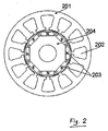
- a currently used as a steering drive 103 permanent magnet synchronous motor is in Fig.
- FIG. 2 illustrated in a schematic plan view and comprises: a stator 201 with grooves 202, in which windings (not shown) are arranged; and a rotor 204 with permanent magnets 203, which are arranged here in the axial direction of the motor within the rotor 204 on its circumference.
- the rotor 204 is located inside the stator 201.
- Performance There are two main issues that such an engine must meet: 1) Performance and 2) Safety.
- Performance parameters such as power density, maximum output torque, torque ripple and cogging torque are important.
- torque ripple the following parameters are of great importance: maximum braking torque, short circuit capability, fault tolerance and simplicity.
- EP 1 770 847 A describes a rotary magnet with permanent magnet.
- the motor has a stator with teeth, which have on their sides facing to a rotor connecting portions with different circumferential lengths.
- through holes are formed with different circumferential lengths, which extend in different axial lengths from the center of the connecting portions to both sides in the axial direction.
- DE 198 42 948 A1 describes a manufacturing method of a laminated core of a stator of an electric motor, with at least one laminations formed by stacked laminations of a stator, consisting of mechanical individual poles and in the circumferential direction of the stator associated Tru laminations, with at least one Polschaft and at least one rotor facing Pole, indentations of the laminations such that the opposite sides of the laminations have projections and thereby form the laminations by intermeshing their impressions and projections as a laminated core of the stator, windings of the mechanical poles of the laminated core, webs between the poles that connect the contiguous mechanical poles in the circumferential direction.
- the axial composition has a predefinable change of poles with connecting web and poles without connecting web. There are five lamellae with poles without connecting bar between one lamella with poles with connecting bar arranged.
- EP 1 542 335 A illustrates a rotor for a rotating electrical machine.
- the rotor has a shaft and a plurality of rotor cores mounted on the shaft and axially split.
- the rotor cores have outer peripheral surfaces with a circular cross-section.
- Permanent magnets extend through the rotor cores and are arranged at equal circumferential intervals. Gaps extend axially through the rotor cores and are formed between the outer peripheral surfaces and the permanent magnets. The gaps of two adjacent rotor cores are arranged circumferentially at different positions.
- JP 2007 151232 A describes a permanent magnet motor and a power steering with such a motor.
- a lamellar stator has stator teeth, some of which are connected and unconnected at their rotor-facing tips.
- the lamellae are mixed layered, with one lamination consisting of a pattern of 2 connected / 10 unconnected / 3 connected / 10 unconnected / 2 connected.
- a rotor is rotated with two to each other about a rotor axis arranged rotor parts, each rotor part is associated with the unconnected fins.
- the present invention therefore has the object of specifying an improved permanent magnet synchronous motor.
- this object is achieved by a permanent magnet synchronous motor with the features of the claim 1 and / or solved by an electric power steering with the features of claim 6.
- a permanent magnet synchronous motor in particular three-phase electric motor having a rotor with permanent magnets, with a stator with stator yoke, in which stator teeth are arranged with Staturnuten therebetween, wherein in each case on a stator tooth at least one winding is provided, wherein the stator teeth as lamellae in Axial direction of the stator are arranged layered and formed at least as two different lamellae, wherein the stator teeth are connected in a first lamination as a stator at their ends facing the rotor with each other circumferentially by means of a connecting bridge and wherein the stator teeth in a second lamination instead of the connecting bridge have an interruption, wherein the rotor has at least two rotor packages, which are arranged in the axial direction of the rotor, wherein the at least two rotor packages are arranged rotated by an offset angle with each other about a rotor axis be Semi asked.
- Such a permanent magnet synchronous motor thus has the advantages of a very low detent torque combined with a high performance and low torque ripple.
- the active axial length Lstk is meant the axial length of the stator with rotor.
- the permanent magnet synchronous motor according to the invention has a lower braking torque compared to conventional permanent magnet synchronous motors, which can be up to 50% lower.
- a starter relay can be omitted because the braking torque is lower.
- the described permanent magnet synchronous motor is preferably suitable for the drive device of a motor vehicle power steering. Conceivable, however, are other applications with other drive devices.
- At least one insulation is provided in each case between the windings in the stator slots. This reduces a probability of insulation errors.
- the windings may be arranged in a three-phase star connection or in a three-phase delta connection.
- a very low braking torque is achieved in the case of faulty insulation compared to conventional motors.
- the delta connection also has the advantage that connection points are reduced compared to the star connection, which are required for conventional permanent magnet synchronous motors with starting relay.
- the rotor can be formed with different permanent magnets in pockets on its circumference, circumferentially on its surface or with ring magnets.
- the permanent magnet synchronous motor has twelve stator slots and eight pole pairs, twelve stator slots and ten pole pairs or twelve stator slots and fourteen pole pairs.
- Fig. 3 shows a schematic plan view of a stator 300 of an embodiment of a permanent magnet synchronous motor according to the invention with a stator yoke 301, in which stator teeth 302 on the inner circumference of the stator yoke 301 are arranged circumferentially.
- stator slots 202 Between the stator teeth 302 are stator slots 202 in which windings 303 are arranged around the stator teeth 302.
- the windings 303 are additionally insulated with an insulation 304 in the stator slots 202.
- the ends of the stator teeth 302 pointing toward the center of the stator yoke 301 are widened so that the stator slots 202 are surrounded radially inward by these widenings and externally by the stator yoke 301 are.
- Fig. 4 is an enlarged schematic plan view of a portion of the stator teeth 302 of the permanent magnet synchronous motor according to the invention Fig. 3 shown.
- the stator teeth 302 are formed as lamellae which are stacked in the axial direction of the stator 300. These fins can have at least two different shapes.
- Fig. 4 shows a first shape in the form of a stator star 305.
- the widened ends of the stator teeth 302 are each connected circumferentially via a connecting bridge 401.
- FIG. 5 A second form of these slats is in Fig. 5 shown, wherein the widened ends of the stator teeth 302 are not connected, but have an interruption 402. They are thus single teeth.
- these fins are arranged alternately stacked, such as Fig. 6 illustrated in an example in perspective.
- connection bridges 401 and interruptions 402 alternate.
- Other arrangements are possible, such as two or three slats with breaks 402 between two connecting bridges 401. Other combinations are of course conceivable.
- FIGS. 7 and 8 show circuit diagrams of windings of the permanent magnet synchronous motor according to the invention, wherein both a conventional star connection after Fig. 7 as well as a delta connection Fig. 8 is possible.
- the delta connection offers the advantage here that only three connections U, V, W are required, which eliminates a star connection or a star connection of the star connection.
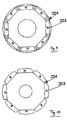
- FIG. 9 to 11 illustrate schematic plan views of three embodiments of a rotor 204 of the invention Permanent magnet synchronous motor after Fig. 3 , Fig. 9 shows on the circumference of the rotor 204 in pockets arranged permanent magnets 203 with different polarity N, S in the axial direction of the rotor 204th Fig. 10 illustrates an arrangement of the permanent magnets 203 on the outer peripheral surface of the rotor 204, and Fig. 11 shows ring magnets on the outer peripheral surface of the rotor 204.
- a fourth embodiment of the rotor of the permanent magnet synchronous motor according to the invention Fig. 3 is in Fig. 12 shown in a schematic perspective view.
- the rotor 204 here consists of two rotor packages 205 which are arranged one behind the other in the axial direction and which are rotated by an offset angle ⁇ , which is preferably half the number of stator slots, about the axial direction relative to one another.
- an offset angle ⁇ is between the first and last rotor package 205th
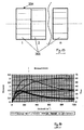
- Fig. 14 is a graphical representation of a braking torque of the permanent magnet synchronous motor according to the invention according to Fig. 3 compared to a conventional permanent magnet synchronous motor over a speed. Torque values are plotted on the left ordinate and I phase on the right phase current values. The upper curve shown with a thick line is the normal braking torque of a conventional permanent magnet synchronous motor which has a maximum at a speed of 220 n -1 , whereas an optimized braking torque of the permanent magnet synchronous motor according to the invention has a maximum at 60 n -1 , which about 50% smaller than that of the conventional permanent magnet synchronous motor.
- the normal phase current I phase is plotted as a thin top line, whereas the optimized phase current I phase of the permanent magnet synchronous motor according to the invention assumes a maximum value which is also about 50% smaller than that of the conventional permanent magnet synchronous motor.
- the permanent magnet synchronous motor according to the invention with a lower braking torque provides greater safety to a conventional motor by blocking the steering in a possible fault, for example in a power steering, not by an excessive braking torque. Due to the lower power consumption of the permanent magnet synchronous motor according to the invention a lower energy consumption is possible.
- the use of the permanent magnet synchronous motor according to the invention in a power steering system of a motor vehicle can be carried out both on the steering gear 101, on the steering shaft 102, on the pinion 105 or elsewhere with corresponding couplings.
- stator teeth 302 it would also be conceivable for the stator teeth 302 to have connecting bridges 401 and interruptions 402 in a same slat plane in a third slat shape.
- the application of the permanent magnet synchronous motor according to the invention for a drive device in a motor vehicle and in particular for a power steering system of a motor vehicle is to be understood merely as an example. Rather, the invention can be advantageously used in any electrical drives.
Abstract
Die vorliegende Erfindung betrifft einen Permanentmagnet-Synchronmotor, insbesondere elektrischer Dreiphasenmotor, mit einem Stator (300) mit Statorjoch (301), in welchem Statorzähne (302) mit dazwischen liegenden Staturnuten (202) angeordnet sind, wobei jeweils auf einem Statorzahn (302) zumindest eine Wicklung (303) vorgesehen ist, mit einem Rotor (204) mit Permanentmagneten (203), wobei die Statorzähne (302) als Lamellen in Axialrichtung des Stators (300) geschichtet angeordnet sind und zumindest als zwei unterschiedliche Lamellen ausgebildet sind, wobei die Statorzähne (302) in einer ersten Lamelle als ein Statorstern (305) an ihren zum Rotor (204) weisenden Enden untereinander umlaufend mittels jeweils einer Verbindungsbrücke (401) verbunden sind und in einer zweiten Lamelle anstelle der Verbindungsbrücke (401) eine Unterbrechung (402) aufweisen. Die vorliegende Erfindung betrifft ferner eine elektrische Servolenkung.

Description
Die vorliegende Erfindung betrifft einen Permanentmagnet-Synchronmotor, insbesondere elektrische Dreiphasenmotor. Die vorliegende Erfindung betrifft weiterhin eine elektrische Servolenkung eines Kraftfahrzeugs.The present invention relates to a permanent magnet synchronous motor, in particular three-phase electric motor. The present invention further relates to an electric power steering system of a motor vehicle.
Derartige Permanentmagnet-Synchronmotoren werden beispielsweise in Antriebseinrichtungen von Kraftfahrzeugen, insbesondere in Servolenkungssystemen und dergleichen, eingesetzt.Such permanent magnet synchronous motors are used for example in drive devices of motor vehicles, in particular in power steering systems and the like.
Servolenkungssysteme sind in
Es gibt zwei Hauptgesichtspunkte, die ein solcher Motor erfüllen muss: 1) Leistungsfähigkeit und 2) Sicherheit. In Bezug auf die Leistungsfähigkeit sind Parameter wie zum Beispiel Leistungsdichte, maximales Ausgangsdrehmoment, Drehmomentschwankung bzw. -welligkeit und Rastmoment bzw. pulsierendes Moment von Bedeutung. Für die Sicherheit sind die folgenden Parameter von großer Wichtigkeit: maximales Bremsmoment, Kurzschlussfähigkeit, Fehlertoleranz und Einfachheit.There are two main issues that such an engine must meet: 1) Performance and 2) Safety. In terms of performance, parameters such as power density, maximum output torque, torque ripple and cogging torque are important. For safety, the following parameters are of great importance: maximum braking torque, short circuit capability, fault tolerance and simplicity.
zwischen den Polen, die die zusammenhängenden mechanischen Pole in Umfangsrichtung verbinden. Die axiale Zusammensetzung weist einen vorgebbaren Wechsel von Polen mit Verbindungssteg und Polen ohne Verbindungssteg auf. Dabei sind fünf Lamellen mit Polen ohne Verbindungssteg zwischen jeweils einer Lamelle mit Polen mit Verbindungssteg angeordnet.
between the poles that connect the contiguous mechanical poles in the circumferential direction. The axial composition has a predefinable change of poles with connecting web and poles without connecting web. There are five lamellae with poles without connecting bar between one lamella with poles with connecting bar arranged.
Die Druckschrift
Die erhöhten Anforderungen an die Einsatzbedingungen in einem Kraftfahrzeug insbesondere in Bezug auf ein möglichst geringes Bauvolumen, niedriges Gewicht, geringe Anzahl der verwendeten Einzelteile und gleichzeitig hohem Wirkungsgrad, und die oben genannten Parameter resultieren in der stets vorhandenen Forderung, einen entsprechend verbesserten Permanentmagnet-Synchronmotor bereitzustellen.The increased demands on the operating conditions in a motor vehicle, in particular with regard to the lowest possible construction volume, low weight, low number of items used and high efficiency, and the above parameters result in the ever-present requirement to provide a correspondingly improved permanent magnet synchronous motor ,
Vor diesem Hintergrund liegt der vorliegenden Erfindung daher die Aufgabe zugrunde, einen verbesserten Permanentmagnet-Synchronmotor anzugeben.Against this background, the present invention therefore has the object of specifying an improved permanent magnet synchronous motor.
Erfindungsgemäß wird diese Aufgabe durch einen Permanentmagnet-Synchronmotor mit den Merkmalen des Patentanspruchs 1 und/oder durch eine elektrische Servolenkung mit den Merkmalen des Patentanspruchs 6 gelöst.According to the invention this object is achieved by a permanent magnet synchronous motor with the features of the
Demgemäß ist ein Permanentmagnet-Synchronmotor, insbesondere elektrischer Dreiphasenmotor, mit einem Rotor mit Permanentmagneten, mit einem Stator mit Statorjoch, in welchem Statorzähne mit dazwischen liegenden Staturnuten angeordnet sind, wobei jeweils auf einem Statorzahn zumindest eine Wicklung vorgesehen ist, wobei die Statorzähne als Lamellen in Axialrichtung des Stators geschichtet angeordnet sind und zumindest als zwei unterschiedliche Lamellen ausgebildet sind, wobei die Statorzähne in einer ersten Lamelle als ein Statorstern an ihren zum Rotor weisenden Enden untereinander umlaufend mittels jeweils einer Verbindungsbrücke verbunden sind und wobei die Statorzähne in einer zweiten Lamelle anstelle der Verbindungsbrücke eine Unterbrechung aufweisen, wobei der Rotor zumindest zwei Rotorpakete aufweist, die in der Axialrichtung des Rotors angeordnet sind, wobei die zumindest zwei Rotorpakete um einen Versatzwinkel untereinander um eine Rotorachse verdreht angeordnet sind bereitgestellt.Accordingly, a permanent magnet synchronous motor, in particular three-phase electric motor having a rotor with permanent magnets, with a stator with stator yoke, in which stator teeth are arranged with Staturnuten therebetween, wherein in each case on a stator tooth at least one winding is provided, wherein the stator teeth as lamellae in Axial direction of the stator are arranged layered and formed at least as two different lamellae, wherein the stator teeth are connected in a first lamination as a stator at their ends facing the rotor with each other circumferentially by means of a connecting bridge and wherein the stator teeth in a second lamination instead of the connecting bridge have an interruption, wherein the rotor has at least two rotor packages, which are arranged in the axial direction of the rotor, wherein the at least two rotor packages are arranged rotated by an offset angle with each other about a rotor axis be Semi asked.
Der Versatzwinkel ist in Winkelgrad kleiner oder gleich der Hälfte der Anzahl der Statornuten, wobei der Versatzwinkel bei mehr als zwei Rotorpaketen zwischen dem ersten und letzten Rotorpaket liegt, wobei die Statorzähne als Lamellen in Axialrichtung des Stators in der Reihenfolge Statorstern mit Verbindungsbrücken gefolgt von einer, zwei oder drei Lamellen jeweils mit nicht verbundenen Statorzähnen als Einzelzähne angeordnet sind, wobei die Lamellen in diesem geschichteten Aufbau in Axialrichtung abwechselnd angeordnet sind, und wobei eine Anzahl n von Rotorpaketen von einer aktiven axialen Länge (Lstk) des Permanentmagnet-Synchronmotors wie folgt abhängig ist:
- n = 1 oder 2, wenn Lstk ≤ 40mm
- n = 2 oder 3, wenn 40 ≤ Lstk ≤ 60mm
- n = 3 oder 4, wenn 60 ≤ Lstk ≤ 80mm
- n = 4, wenn 80 ≤ Lstk ≤ 130mm.
- n = 1 or 2, if Lstk ≤ 40mm
- n = 2 or 3 if 40 ≤ Lstk ≤ 60mm
- n = 3 or 4 if 60 ≤ Lstk ≤ 80mm
- n = 4, if 80 ≤ Lstk ≤ 130mm.
Ein solcher Permanentmagnet-Synchronmotors weist damit die Vorteile eines sehr geringen Rastmomentes verbunden mit einer hohen Leistungsfähigkeit und gleichzeitig niedriger Momentwelligkeit auf.Such a permanent magnet synchronous motor thus has the advantages of a very low detent torque combined with a high performance and low torque ripple.
Unter der aktiven axialen Länge Lstk ist die axiale Länge des Stators mit Rotor zu verstehen.By the active axial length Lstk is meant the axial length of the stator with rotor.
Ein weiterer Vorteil besteht darin, dass der erfindungsgemäße Permanentmagnet-Synchronmotor ein im Vergleich zu herkömmlichen Permanentmagnet-Synchronmotoren niedrigeres Bremsmoment aufweist, welches bis zu 50% geringer sein kann.Another advantage is that the permanent magnet synchronous motor according to the invention has a lower braking torque compared to conventional permanent magnet synchronous motors, which can be up to 50% lower.
Zudem ergibt sich der Vorteil hoher Leistungsfähigkeit bei gleichzeitigem Sicherheitsbereich ermöglicht.In addition, there is the advantage of high performance with simultaneous security range allows.
Gleichzeitig kann damit auch ein Startrelais entfallen, da die Bremsmomente geringer ausfallen.At the same time, a starter relay can be omitted because the braking torque is lower.
Der beschriebene Permanentmagnet-Synchronmotor ist bevorzugt für die Antriebseinrichtung einer Kraftfahrzeug-Servolenkung geeignet. Denkbar sind aber auch andere Anwendungen bei anderen Antriebseinrichtungen.The described permanent magnet synchronous motor is preferably suitable for the drive device of a motor vehicle power steering. Conceivable, however, are other applications with other drive devices.
Vorteilhafte Ausgestaltungen und Weiterbildungen der Erfindung ergeben sich aus den Unteransprüchen sowie aus der Beschreibung in Zusammenschau mit den Figuren der Zeichnung.Advantageous embodiments and modifications of the invention will become apparent from the dependent claims and from the description in conjunction with the figures of the drawing.
In weiterer bevorzugter Ausführung ist zwischen den Wicklungen in den Statornuten jeweils zumindest eine Isolierung vorgesehen. Dadurch wird eine Wahrscheinlichkeit von Isolationsfehlern geringer.In a further preferred embodiment, at least one insulation is provided in each case between the windings in the stator slots. This reduces a probability of insulation errors.
Die Wicklungen können in einer Dreiphasen-Sternschaltung oder in einer Dreiphasen-Dreieckschaltung angeordnet sein. Dadurch wird im Fall fehlerhafter Isolation im Vergleich zu herkömmlichen Motoren ein sehr geringes Bremsmoment erzielt. Die Dreieckschaltung bietet auch den Vorteil, dass Verbindungsstellen im Vergleich zur Sternschaltung, welche für herkömmliche Permanentmagnet-Synchronmotoren mit Startrelais erforderlich sind, verringert sind.The windings may be arranged in a three-phase star connection or in a three-phase delta connection. As a result, a very low braking torque is achieved in the case of faulty insulation compared to conventional motors. The delta connection also has the advantage that connection points are reduced compared to the star connection, which are required for conventional permanent magnet synchronous motors with starting relay.
Der Rotor kann unterschiedliche mit Permanentmagneten in Taschen an seinem Umfang, umfänglich auf seiner Oberfläche oder mit Ringmagneten ausgebildet sein.The rotor can be formed with different permanent magnets in pockets on its circumference, circumferentially on its surface or with ring magnets.
In bevorzugten Ausführungen weist der Permanentmagnet-Synchronmotor zwölf Statornuten und acht Polpaare, zwölf Statornuten und zehn Polpaare oder zwölf Statornuten und vierzehn Polpaare auf.In preferred embodiments, the permanent magnet synchronous motor has twelve stator slots and eight pole pairs, twelve stator slots and ten pole pairs or twelve stator slots and fourteen pole pairs.
Im Vergleich zu einem herkömmlichen Permanentmagnet-Synchronmotor weist der erfindungsgemäße Permanentmagnet-Synchronmotor folgende Vorteile auf:
- Erhöhte Leistungsfähigkeit von ca. 10%
- Um ca. 50% niedrigeres Bremsmoment
- Erhöhte Motorinduktivität für kleine Ströme
- Reduziertes Rastmoment
- Reduzierte Momentenwelligkeit
- Kein Relais erforderlich
- Dreieckschaltung kann verwendet werden
- Ausgezeichnete Wicklungs-/Phasenisolation
- Einfachere Statorkonstruktion
- Einfachere Rotorkonstruktion
- Increased efficiency of approx. 10%
- About 50% lower braking torque
- Increased motor inductance for small currents
- Reduced cogging torque
- Reduced torque ripple
- No relay required
- Delta connection can be used
- Excellent winding / phase insulation
- Simpler stator construction
- Simpler rotor design
Die obigen Ausgestaltungen und Weiterbildungen der Erfindung lassen sich auf beliebige Art und Weise miteinander kombinieren.The above refinements and developments of the invention can be combined with one another in any desired manner.
Die vorliegende Erfindung wird nachfolgend anhand der in den schematischen Figuren der Zeichnung angegebenen Ausführungsbeispiele näher erläutert. Es zeigen dabei:
- Fig. 1a-c
- schematische Darstellungen von Servolenkungssystemen mit Lenkantrieben in unterschiedlichen Einbaupositionen;
- Fig. 2
- eine schematische Draufsicht auf einen Permanentmagnet-Synchronmotor;
- Fig. 3
- eine schematische Draufsicht auf einen Stator eines Ausführungsbeispiels eines erfindungsgemäßen Permanentmagnet-Synchronmotors;
- Fig. 4
- eine vergrößerte schematische Draufsicht auf einen Teilabschnitt von Statorzähnen des erfindungsgemäßen Permanentmagnet-Synchronmotors nach
Fig. 3 ; - Fig. 5
- eine vergrößerte schematische Draufsicht auf einzelne Statorzähne des erfindungsgemäßen Permanentmagnet-Synchronmotors nach
Fig. 3 ; - Fig. 6
- eine vergrößerte, schematische perspektivische Ansicht auf Statorsterne und Statorzähne des erfindungsgemäßen PermanentmagnetSynchronmotors nach
Fig. 3 ; - Fig. 7-8
- Schaltbilder von Wicklungen des erfindungsgemäßen Permanentmagnet-Synchronmotors nach
Fig. 3 ; - Fig. 9-11
- schematische Draufsichten auf drei Ausführungsbeispiele eines Rotors des erfindungsgemäßen Permanentmagnet-Synchronmotors nach
Fig. 3 ; - Fig. 12
- eine schematische perspektivische Ansicht eines vierten Ausführungsbeispiels des Rotors des erfindungsgemäßen Permanentmagnet-Synchronmotors nach
Fig. 3 ; - Fig. 13
- eine schematische Seitenansicht des vierten Ausführungsbeispiels des Rotors nach
Fig. 12 ; und - Fig. 14
- eine grafische Darstellung eines Bremsmomentes über einer Drehzahl des erfindungsgemäßen Permanentmagnet-Synchronmotors nach
Fig. 3 im Vergleich zu einem herkömmlichen Permanentmagnet-Synchronmotor.
- Fig. 1a-c
- schematic representations of power steering systems with steering drives in different mounting positions;
- Fig. 2
- a schematic plan view of a permanent magnet synchronous motor;
- Fig. 3
- a schematic plan view of a stator of an embodiment of a permanent magnet synchronous motor according to the invention;
- Fig. 4
- an enlarged schematic plan view of a portion of stator teeth of the permanent magnet synchronous motor according to the invention
Fig. 3 ; - Fig. 5
- an enlarged schematic plan view of individual stator teeth of the permanent magnet synchronous motor according to the invention
Fig. 3 ; - Fig. 6
- an enlarged, schematic perspective view of stator stars and stator teeth of the permanent magnet synchronous motor according to the invention
Fig. 3 ; - Fig. 7-8
- Wiring diagrams of windings of the permanent magnet synchronous motor according to the invention
Fig. 3 ; - Fig. 9-11
- schematic plan views of three embodiments of a rotor of the permanent magnet synchronous motor according to the invention according to
Fig. 3 ; - Fig. 12
- a schematic perspective view of a fourth embodiment of the rotor of the permanent magnet synchronous motor according to the invention according to
Fig. 3 ; - Fig. 13
- a schematic side view of the fourth embodiment of the rotor according to
Fig. 12 ; and - Fig. 14
- a graphic representation of a braking torque over a speed of the permanent magnet synchronous motor according to the invention
Fig. 3 compared to a conventional permanent magnet synchronous motor.
In den Figuren der Zeichnung sind gleiche und funktionsgleiche Elemente und Merkmale - sofern nichts Anderes ausgeführt ist - mit denselben Bezugszeichen versehen.In the figures of the drawing are identical and functionally identical elements and features - unless otherwise stated - provided with the same reference numerals.
Servolenksysteme und Grundaufbau eines Permanentmagnet-Synchronmotors sind bereits oben mit Bezugnahme auf
In
Eine zweite Form dieser Lamellen ist in
Ein viertes Ausführungsbeispiels des Rotors des erfindungsgemäßen Permanentmagnet-Synchronmotors nach
Der Einsatz des erfindungsgemäßen Permanentmagnet-Synchronmotors in einem Servolenksystem eines Kraftfahrzeugs kann sowohl am Lenkgetriebe 101, an der Lenkwelle 102, an dem Ritzel 105 oder auch an anderer Stelle mit entsprechenden Kopplungen erfolgen.The use of the permanent magnet synchronous motor according to the invention in a power steering system of a motor vehicle can be carried out both on the
Obgleich die vorliegende Erfindung vorstehend anhand eines bevorzugten Ausführungsbeispiels erläutert wurde, sei sie nicht darauf beschränkt, sondern lässt sich auf beliebige Art und Weise modifizieren, ohne vom Gegenstand der vorliegenden Erfindung abzuweichen.Although the present invention has been explained above with reference to a preferred embodiment, it is not limited thereto, but may be modified in any manner without departing from the subject matter of the present invention.
Insbesondere wäre auch denkbar, dass die Statorzähne 302 in einer dritten Lamellenform Verbindungsbrücken 401 und Unterbrechungen 402 in einer gleichen Lamellenebene aufweisen.In particular, it would also be conceivable for the
Auch die Anwendung des erfindungsgemäßen Permanentmagnet-Synchronmotors für eine Antriebsvorrichtung in einem Kraftfahrzeug und hier insbesondere für ein Servolenksystem eines Kraftfahrzeuges sei lediglich beispielhaft zu verstehen. Die Erfindung lässt sich vielmehr bei beliebigen elektrischen Antrieben vorteilhaft einsetzen.The application of the permanent magnet synchronous motor according to the invention for a drive device in a motor vehicle and in particular for a power steering system of a motor vehicle is to be understood merely as an example. Rather, the invention can be advantageously used in any electrical drives.
Die vorstehend genannten Zahlenangaben sind zwar bevorzugt und bisweilen einer konkreten Anwendung entnommen, jedoch können diese, entsprechend dem fachmännischen Handeln und Wissen, auch mehr oder weniger variiert werden.Although the abovementioned figures are preferred and sometimes taken from a specific application, however These can also be more or less varied according to the expert's actions and knowledge.
- 101101
- Lenkgetriebesteering gear
- 102102
- Lenkwellesteering shaft
- 103103
- Motorengine
- 104104
- Steuereinheitcontrol unit
- 105105
- Ritzelpinion
- 106106
- Radwheel
- 107107
- Spurstangetie rod
- 201201
- Statorstator
- 202202
- Statornutstator
- 203203
- Permanentmagnetpermanent magnet
- 204204
- Rotorrotor
- 205205
- Rotorpaketrotor pack
- 301301
- Statorjochstator yoke
- 302302
- Statorzahnstator tooth
- 303303
- Wicklungwinding
- 304304
- Isolierunginsulation
- 305305
- Statorsternstator star
- 401401
- Verbindungsbrückeconnecting bridge
- 402402
- Unterbrechunginterruption
- N, SN, S
- Magnetpolemagnetic poles
- U, V, WAND MANY MORE
- Anschlussconnection
- γγ
- Versatzwinkeloffset angle
Claims (6)
dadurch gekennzeichnet, dass
characterized in that
dadurch gekennzeichnet,
dass zwischen den Wicklungen (303) in den Statornuten (202) jeweils zumindest eine Isolierung (304) vorgesehen ist.Synchronous motor according to claim 1,
characterized,
in that at least one insulation (304) is provided in each case between the windings (303) in the stator slots (202).
dadurch gekennzeichnet,
dass die Wicklungen (303) in einer Dreiphasen-Sternschaltung oder in einer Dreiphasen-Dreieckschaltung angeordnet sind.Synchronous motor according to one of the preceding claims,
characterized,
in that the windings (303) are arranged in a three-phase star connection or in a three-phase delta connection.
dadurch gekennzeichnet,
dass der Rotor (204) Permanentmagnete (203) in Taschen an seinem Umfang, umfänglich auf seiner Oberfläche oder als Ringmagnete aufweist.Synchronous motor according to one of the preceding claims,
characterized,
in that the rotor (204) has permanent magnets (203) in pockets on its circumference, peripherally on its surface or as ring magnets.
dadurch gekennzeichnet,
dass der Permanentmagnet-Synchronmotor zwölf Statornuten (202) und acht Polpaare, zwölf Statornuten (202) und zehn Polpaare oder zwölf Statornuten (202) und vierzehn Polpaare aufweist.Synchronous motor according to one of the preceding claims,
characterized,
that the permanent magnet synchronous motor twelve stator slots (202) and eight pairs of poles, twelve stator slots (202) and ten pairs of poles or twelve stator slots (202) and having pole pairs fourteen.
Applications Claiming Priority (2)
| Application Number | Priority Date | Filing Date | Title |
|---|---|---|---|
| DE102008042100A DE102008042100A1 (en) | 2008-09-15 | 2008-09-15 | Permanent magnet synchronous motor and electric power steering |
| EP09743837.8A EP2327136B1 (en) | 2008-09-15 | 2009-09-14 | Permanent-magnet synchronous motor and electric power-assisted steering system |
Related Parent Applications (2)
| Application Number | Title | Priority Date | Filing Date |
|---|---|---|---|
| EP09743837.8A Division-Into EP2327136B1 (en) | 2008-09-15 | 2009-09-14 | Permanent-magnet synchronous motor and electric power-assisted steering system |
| EP09743837.8A Division EP2327136B1 (en) | 2008-09-15 | 2009-09-14 | Permanent-magnet synchronous motor and electric power-assisted steering system |
Publications (2)
| Publication Number | Publication Date |
|---|---|
| EP3038233A1 true EP3038233A1 (en) | 2016-06-29 |
| EP3038233B1 EP3038233B1 (en) | 2017-05-03 |
Family
ID=41416029
Family Applications (2)
| Application Number | Title | Priority Date | Filing Date |
|---|---|---|---|
| EP15198633.8A Not-in-force EP3038233B1 (en) | 2008-09-15 | 2009-09-14 | Permanent-magnet synchronous motor and electric power steering |
| EP09743837.8A Not-in-force EP2327136B1 (en) | 2008-09-15 | 2009-09-14 | Permanent-magnet synchronous motor and electric power-assisted steering system |
Family Applications After (1)
| Application Number | Title | Priority Date | Filing Date |
|---|---|---|---|
| EP09743837.8A Not-in-force EP2327136B1 (en) | 2008-09-15 | 2009-09-14 | Permanent-magnet synchronous motor and electric power-assisted steering system |
Country Status (6)
| Country | Link |
|---|---|
| US (1) | US8614532B2 (en) |
| EP (2) | EP3038233B1 (en) |
| KR (1) | KR101485586B1 (en) |
| CN (2) | CN104868679B (en) |
| DE (1) | DE102008042100A1 (en) |
| WO (1) | WO2010028639A1 (en) |
Families Citing this family (12)
| Publication number | Priority date | Publication date | Assignee | Title |
|---|---|---|---|---|
| KR101313447B1 (en) * | 2011-11-29 | 2013-10-01 | 엘지이노텍 주식회사 | Stator Core |
| EP2665156A1 (en) * | 2012-05-14 | 2013-11-20 | Grundfos Holding A/S | Rotor for an electric motor |
| DE102012213465A1 (en) * | 2012-07-31 | 2014-02-06 | Brose Fahrzeugteile GmbH & Co. Kommanditgesellschaft, Würzburg | Permanent magnet synchronous motor and power steering assembly |
| JP2014064395A (en) * | 2012-09-21 | 2014-04-10 | Sanyo Denki Co Ltd | Embedded permanent magnet motor and rotor |
| US9214837B2 (en) | 2013-12-13 | 2015-12-15 | Arm Limited | Electric motor with plural stator components |
| NL2013403B1 (en) * | 2014-09-02 | 2016-09-26 | Elsio Cicilia Beremundo | Synchronous rotary motor or generator provided with various rotors and / or stators. |
| DE102014222245A1 (en) | 2014-10-31 | 2016-05-04 | Brose Fahrzeugteile GmbH & Co. Kommanditgesellschaft, Würzburg | Stator arrangement for an electric motor, electric motor and method for producing a stator assembly |
| DE102016201967A1 (en) * | 2016-02-10 | 2017-08-10 | Robert Bosch Gmbh | Stator for an electric machine, in particular for a Innenäulfer electric motor |
| CN106685113B (en) * | 2017-02-28 | 2019-04-23 | 合肥工业大学 | A kind of cast-aluminum rotor tooth slot structure |
| CN106602755A (en) * | 2017-02-28 | 2017-04-26 | 合肥工业大学 | Separable stator motor |
| JP6900846B2 (en) * | 2017-09-05 | 2021-07-07 | 株式会社デンソー | Stator core |
| CN109120080A (en) * | 2018-09-19 | 2019-01-01 | 珠海格力电器股份有限公司 | Motor stator, motor and bus |
Citations (4)
| Publication number | Priority date | Publication date | Assignee | Title |
|---|---|---|---|---|
| DE19842948A1 (en) | 1998-09-18 | 2000-03-30 | Siemens Ag | Electric motor |
| EP1542335A1 (en) | 2003-12-08 | 2005-06-15 | Nissan Motor Co., Ltd. | Rotor for rotary electric machine |
| EP1770847A2 (en) | 2005-09-20 | 2007-04-04 | Sanyo Denki Co., Ltd. | Permanent magnet rotary motor |
| JP2007151232A (en) | 2005-11-24 | 2007-06-14 | Toshiba Corp | Permanent magnet motor and electric power steering apparatus using the same |
Family Cites Families (9)
| Publication number | Priority date | Publication date | Assignee | Title |
|---|---|---|---|---|
| ITTO980343A1 (en) * | 1998-04-23 | 1999-10-23 | Bitron Spa | ELECTRONICALLY COMMUTED ELECTRIC MOTOR |
| US6597078B2 (en) * | 2000-12-04 | 2003-07-22 | Emerson Electric Co. | Electric power steering system including a permanent magnet motor |
| JP2003032936A (en) * | 2001-07-16 | 2003-01-31 | Matsushita Electric Ind Co Ltd | Electric motor |
| DE10147073A1 (en) * | 2001-09-25 | 2003-04-30 | Minebea Co Ltd | Electric motor, in particular electronically commutated direct current motor |
| US6822364B2 (en) * | 2002-07-30 | 2004-11-23 | Asmo Co., Ltd. | Brushless motor |
| JP2006187130A (en) * | 2004-12-28 | 2006-07-13 | Hitachi Ltd | Electric power steering system using winding lead-acid battery, and motor and inverter device used therefor |
| ITRE20050029A1 (en) * | 2005-03-24 | 2006-09-25 | Motor Power Co Srl | THREE-PHASE ELECTRIC MOTOR WITH HIGH PAIR |
| JP4691376B2 (en) * | 2005-03-25 | 2011-06-01 | 山洋電気株式会社 | Permanent magnet type rotary motor |
| JP2008228390A (en) * | 2007-03-09 | 2008-09-25 | Jtekt Corp | Brushless motor and electric power steering device equipped with the same |
-
2008
- 2008-09-15 DE DE102008042100A patent/DE102008042100A1/en not_active Withdrawn
-
2009
- 2009-09-14 US US13/119,013 patent/US8614532B2/en active Active
- 2009-09-14 WO PCT/DE2009/001275 patent/WO2010028639A1/en active Application Filing
- 2009-09-14 KR KR1020117006731A patent/KR101485586B1/en active IP Right Grant
- 2009-09-14 EP EP15198633.8A patent/EP3038233B1/en not_active Not-in-force
- 2009-09-14 CN CN201510158399.0A patent/CN104868679B/en not_active Expired - Fee Related
- 2009-09-14 CN CN200980140461.6A patent/CN102177638B/en not_active Expired - Fee Related
- 2009-09-14 EP EP09743837.8A patent/EP2327136B1/en not_active Not-in-force
Patent Citations (4)
| Publication number | Priority date | Publication date | Assignee | Title |
|---|---|---|---|---|
| DE19842948A1 (en) | 1998-09-18 | 2000-03-30 | Siemens Ag | Electric motor |
| EP1542335A1 (en) | 2003-12-08 | 2005-06-15 | Nissan Motor Co., Ltd. | Rotor for rotary electric machine |
| EP1770847A2 (en) | 2005-09-20 | 2007-04-04 | Sanyo Denki Co., Ltd. | Permanent magnet rotary motor |
| JP2007151232A (en) | 2005-11-24 | 2007-06-14 | Toshiba Corp | Permanent magnet motor and electric power steering apparatus using the same |
Non-Patent Citations (2)
| Title |
|---|
| NICOLA BIANCHI ET AL.: "IEEE TRANSACTIONS ON INDUSTRY APPLICATIONS", vol. 38, 1 September 2002, IEEE SERVICE CENTER, article "Design Techniques for Reducing the Cogging Torque in Surface-Mounted PM Motors" |
| NICOLA BIANCHI ET AL: "Design Techniques for Reducing the Cogging Torque in Surface-Mounted PM Motors", IEEE TRANSACTIONS ON INDUSTRY APPLICATIONS, IEEE SERVICE CENTER, PISCATAWAY, NJ, US, vol. 38, no. 5, 1 September 2002 (2002-09-01), XP011073515, ISSN: 0093-9994 * |
Also Published As
| Publication number | Publication date |
|---|---|
| EP2327136B1 (en) | 2016-08-17 |
| CN102177638A (en) | 2011-09-07 |
| KR20110069022A (en) | 2011-06-22 |
| KR101485586B1 (en) | 2015-01-23 |
| US8614532B2 (en) | 2013-12-24 |
| WO2010028639A1 (en) | 2010-03-18 |
| CN104868679A (en) | 2015-08-26 |
| EP2327136A1 (en) | 2011-06-01 |
| DE102008042100A1 (en) | 2010-03-18 |
| CN104868679B (en) | 2018-12-21 |
| EP3038233B1 (en) | 2017-05-03 |
| US20120098376A1 (en) | 2012-04-26 |
| CN102177638B (en) | 2015-05-06 |
Similar Documents
| Publication | Publication Date | Title |
|---|---|---|
| EP3038233B1 (en) | Permanent-magnet synchronous motor and electric power steering | |
| DE102006025396B4 (en) | A-phase brushless motor | |
| EP2115857B1 (en) | 18/8 synchronous motor | |
| WO2009000578A2 (en) | Synchronous motor having 12 stator teeth and 10 rotor poles | |
| EP2427951B1 (en) | Synchronous electric machine | |
| EP3479462B1 (en) | Electrical machine system | |
| EP3352331A1 (en) | Rotor sheet for a permanently excited electric motor and rotor | |
| EP2550721B1 (en) | Electric machine and steering device | |
| EP2517334B1 (en) | Rotor for an electric machine | |
| EP3479458A1 (en) | Rotor, method for producing a rotor, reluctance machine and working machine | |
| WO2015007441A2 (en) | Electric machine and arrangement of electric machines | |
| DE102016212022A1 (en) | rotor | |
| EP2532073B1 (en) | Stator of a permanently excited rotating electric machine | |
| EP2880750B1 (en) | Permanent magnet synchronous motor and power-assisted steering system | |
| EP3457533B1 (en) | Rotor for an electrical machine | |
| DE102015105991B4 (en) | High power density electrical work machine | |
| DE102010028869A1 (en) | Direct current generator i.e. wind power generator, has stator including single-layer winding system constructed of several winding segments, where each winding segment includes open slots for winding of three stator coils | |
| EP3326266B1 (en) | High-speed motor with air gap winding | |
| WO2024067918A1 (en) | Rotor and electric machine | |
| EP2532074B1 (en) | Stator of a permanently excited rotating electric machine | |
| WO2019179558A1 (en) | Connection of "n"-busbars in an electric motor | |
| EP3706288A1 (en) | Sheet package for an electric machine | |
| DE102013207017A1 (en) | Non-salient pole rotor for electromotor for e.g. mill drive, has circle segments exhibiting segment height equal to half difference, and metal sheets laminated such that metal sheets are rotated relative to adjacent metal sheet at angle |
Legal Events
| Date | Code | Title | Description |
|---|---|---|---|
| PUAI | Public reference made under article 153(3) epc to a published international application that has entered the european phase |
Free format text: ORIGINAL CODE: 0009012 |
|
| AC | Divisional application: reference to earlier application |
Ref document number: 2327136 Country of ref document: EP Kind code of ref document: P |
|
| AK | Designated contracting states |
Kind code of ref document: A1 Designated state(s): AT BE BG CH CY CZ DE DK EE ES FI FR GB GR HR HU IE IS IT LI LT LU LV MC MK MT NL NO PL PT RO SE SI SK SM TR |
|
| 17P | Request for examination filed |
Effective date: 20161010 |
|
| RBV | Designated contracting states (corrected) |
Designated state(s): AT BE BG CH CY CZ DE DK EE ES FI FR GB GR HR HU IE IS IT LI LT LU LV MC MK MT NL NO PL PT RO SE SI SK SM TR |
|
| GRAP | Despatch of communication of intention to grant a patent |
Free format text: ORIGINAL CODE: EPIDOSNIGR1 |
|
| STAA | Information on the status of an ep patent application or granted ep patent |
Free format text: STATUS: GRANT OF PATENT IS INTENDED |
|
| INTG | Intention to grant announced |
Effective date: 20161216 |
|
| GRAS | Grant fee paid |
Free format text: ORIGINAL CODE: EPIDOSNIGR3 |
|
| GRAA | (expected) grant |
Free format text: ORIGINAL CODE: 0009210 |
|
| STAA | Information on the status of an ep patent application or granted ep patent |
Free format text: STATUS: THE PATENT HAS BEEN GRANTED |
|
| AC | Divisional application: reference to earlier application |
Ref document number: 2327136 Country of ref document: EP Kind code of ref document: P |
|
| AK | Designated contracting states |
Kind code of ref document: B1 Designated state(s): AT BE BG CH CY CZ DE DK EE ES FI FR GB GR HR HU IE IS IT LI LT LU LV MC MK MT NL NO PL PT RO SE SI SK SM TR |
|
| REG | Reference to a national code |
Ref country code: GB Ref legal event code: FG4D Free format text: NOT ENGLISH |
|
| REG | Reference to a national code |
Ref country code: AT Ref legal event code: REF Ref document number: 890990 Country of ref document: AT Kind code of ref document: T Effective date: 20170515 Ref country code: CH Ref legal event code: EP |
|
| REG | Reference to a national code |
Ref country code: IE Ref legal event code: FG4D Free format text: LANGUAGE OF EP DOCUMENT: GERMAN |
|
| REG | Reference to a national code |
Ref country code: DE Ref legal event code: R096 Ref document number: 502009013943 Country of ref document: DE |
|
| REG | Reference to a national code |
Ref country code: FR Ref legal event code: PLFP Year of fee payment: 9 |
|
| REG | Reference to a national code |
Ref country code: NL Ref legal event code: MP Effective date: 20170503 |
|
| REG | Reference to a national code |
Ref country code: LT Ref legal event code: MG4D |
|
| PG25 | Lapsed in a contracting state [announced via postgrant information from national office to epo] |
Ref country code: GR Free format text: LAPSE BECAUSE OF FAILURE TO SUBMIT A TRANSLATION OF THE DESCRIPTION OR TO PAY THE FEE WITHIN THE PRESCRIBED TIME-LIMIT Effective date: 20170804 Ref country code: HR Free format text: LAPSE BECAUSE OF FAILURE TO SUBMIT A TRANSLATION OF THE DESCRIPTION OR TO PAY THE FEE WITHIN THE PRESCRIBED TIME-LIMIT Effective date: 20170503 Ref country code: NO Free format text: LAPSE BECAUSE OF FAILURE TO SUBMIT A TRANSLATION OF THE DESCRIPTION OR TO PAY THE FEE WITHIN THE PRESCRIBED TIME-LIMIT Effective date: 20170803 Ref country code: ES Free format text: LAPSE BECAUSE OF FAILURE TO SUBMIT A TRANSLATION OF THE DESCRIPTION OR TO PAY THE FEE WITHIN THE PRESCRIBED TIME-LIMIT Effective date: 20170503 Ref country code: FI Free format text: LAPSE BECAUSE OF FAILURE TO SUBMIT A TRANSLATION OF THE DESCRIPTION OR TO PAY THE FEE WITHIN THE PRESCRIBED TIME-LIMIT Effective date: 20170503 Ref country code: LT Free format text: LAPSE BECAUSE OF FAILURE TO SUBMIT A TRANSLATION OF THE DESCRIPTION OR TO PAY THE FEE WITHIN THE PRESCRIBED TIME-LIMIT Effective date: 20170503 |
|
| PG25 | Lapsed in a contracting state [announced via postgrant information from national office to epo] |
Ref country code: LV Free format text: LAPSE BECAUSE OF FAILURE TO SUBMIT A TRANSLATION OF THE DESCRIPTION OR TO PAY THE FEE WITHIN THE PRESCRIBED TIME-LIMIT Effective date: 20170503 Ref country code: PL Free format text: LAPSE BECAUSE OF FAILURE TO SUBMIT A TRANSLATION OF THE DESCRIPTION OR TO PAY THE FEE WITHIN THE PRESCRIBED TIME-LIMIT Effective date: 20170503 Ref country code: SE Free format text: LAPSE BECAUSE OF FAILURE TO SUBMIT A TRANSLATION OF THE DESCRIPTION OR TO PAY THE FEE WITHIN THE PRESCRIBED TIME-LIMIT Effective date: 20170503 Ref country code: IS Free format text: LAPSE BECAUSE OF FAILURE TO SUBMIT A TRANSLATION OF THE DESCRIPTION OR TO PAY THE FEE WITHIN THE PRESCRIBED TIME-LIMIT Effective date: 20170903 Ref country code: NL Free format text: LAPSE BECAUSE OF FAILURE TO SUBMIT A TRANSLATION OF THE DESCRIPTION OR TO PAY THE FEE WITHIN THE PRESCRIBED TIME-LIMIT Effective date: 20170503 Ref country code: BG Free format text: LAPSE BECAUSE OF FAILURE TO SUBMIT A TRANSLATION OF THE DESCRIPTION OR TO PAY THE FEE WITHIN THE PRESCRIBED TIME-LIMIT Effective date: 20170803 |
|
| PG25 | Lapsed in a contracting state [announced via postgrant information from national office to epo] |
Ref country code: RO Free format text: LAPSE BECAUSE OF FAILURE TO SUBMIT A TRANSLATION OF THE DESCRIPTION OR TO PAY THE FEE WITHIN THE PRESCRIBED TIME-LIMIT Effective date: 20170503 Ref country code: EE Free format text: LAPSE BECAUSE OF FAILURE TO SUBMIT A TRANSLATION OF THE DESCRIPTION OR TO PAY THE FEE WITHIN THE PRESCRIBED TIME-LIMIT Effective date: 20170503 Ref country code: SK Free format text: LAPSE BECAUSE OF FAILURE TO SUBMIT A TRANSLATION OF THE DESCRIPTION OR TO PAY THE FEE WITHIN THE PRESCRIBED TIME-LIMIT Effective date: 20170503 Ref country code: DK Free format text: LAPSE BECAUSE OF FAILURE TO SUBMIT A TRANSLATION OF THE DESCRIPTION OR TO PAY THE FEE WITHIN THE PRESCRIBED TIME-LIMIT Effective date: 20170503 Ref country code: CZ Free format text: LAPSE BECAUSE OF FAILURE TO SUBMIT A TRANSLATION OF THE DESCRIPTION OR TO PAY THE FEE WITHIN THE PRESCRIBED TIME-LIMIT Effective date: 20170503 |
|
| REG | Reference to a national code |
Ref country code: DE Ref legal event code: R097 Ref document number: 502009013943 Country of ref document: DE |
|
| PG25 | Lapsed in a contracting state [announced via postgrant information from national office to epo] |
Ref country code: IT Free format text: LAPSE BECAUSE OF FAILURE TO SUBMIT A TRANSLATION OF THE DESCRIPTION OR TO PAY THE FEE WITHIN THE PRESCRIBED TIME-LIMIT Effective date: 20170503 Ref country code: SM Free format text: LAPSE BECAUSE OF FAILURE TO SUBMIT A TRANSLATION OF THE DESCRIPTION OR TO PAY THE FEE WITHIN THE PRESCRIBED TIME-LIMIT Effective date: 20170503 |
|
| PLBE | No opposition filed within time limit |
Free format text: ORIGINAL CODE: 0009261 |
|
| STAA | Information on the status of an ep patent application or granted ep patent |
Free format text: STATUS: NO OPPOSITION FILED WITHIN TIME LIMIT |
|
| 26N | No opposition filed |
Effective date: 20180206 |
|
| REG | Reference to a national code |
Ref country code: CH Ref legal event code: PL |
|
| GBPC | Gb: european patent ceased through non-payment of renewal fee |
Effective date: 20170914 |
|
| PG25 | Lapsed in a contracting state [announced via postgrant information from national office to epo] |
Ref country code: MC Free format text: LAPSE BECAUSE OF FAILURE TO SUBMIT A TRANSLATION OF THE DESCRIPTION OR TO PAY THE FEE WITHIN THE PRESCRIBED TIME-LIMIT Effective date: 20170503 |
|
| REG | Reference to a national code |
Ref country code: IE Ref legal event code: MM4A |
|
| REG | Reference to a national code |
Ref country code: BE Ref legal event code: MM Effective date: 20170930 |
|
| PG25 | Lapsed in a contracting state [announced via postgrant information from national office to epo] |
Ref country code: LU Free format text: LAPSE BECAUSE OF NON-PAYMENT OF DUE FEES Effective date: 20170914 |
|
| PG25 | Lapsed in a contracting state [announced via postgrant information from national office to epo] |
Ref country code: CH Free format text: LAPSE BECAUSE OF NON-PAYMENT OF DUE FEES Effective date: 20170930 Ref country code: IE Free format text: LAPSE BECAUSE OF NON-PAYMENT OF DUE FEES Effective date: 20170914 Ref country code: GB Free format text: LAPSE BECAUSE OF NON-PAYMENT OF DUE FEES Effective date: 20170914 Ref country code: LI Free format text: LAPSE BECAUSE OF NON-PAYMENT OF DUE FEES Effective date: 20170930 |
|
| REG | Reference to a national code |
Ref country code: FR Ref legal event code: PLFP Year of fee payment: 10 |
|
| PG25 | Lapsed in a contracting state [announced via postgrant information from national office to epo] |
Ref country code: BE Free format text: LAPSE BECAUSE OF NON-PAYMENT OF DUE FEES Effective date: 20170930 |
|
| PG25 | Lapsed in a contracting state [announced via postgrant information from national office to epo] |
Ref country code: MT Free format text: LAPSE BECAUSE OF FAILURE TO SUBMIT A TRANSLATION OF THE DESCRIPTION OR TO PAY THE FEE WITHIN THE PRESCRIBED TIME-LIMIT Effective date: 20170503 |
|
| REG | Reference to a national code |
Ref country code: AT Ref legal event code: MM01 Ref document number: 890990 Country of ref document: AT Kind code of ref document: T Effective date: 20170914 |
|
| PG25 | Lapsed in a contracting state [announced via postgrant information from national office to epo] |
Ref country code: AT Free format text: LAPSE BECAUSE OF NON-PAYMENT OF DUE FEES Effective date: 20170914 |
|
| PG25 | Lapsed in a contracting state [announced via postgrant information from national office to epo] |
Ref country code: HU Free format text: LAPSE BECAUSE OF FAILURE TO SUBMIT A TRANSLATION OF THE DESCRIPTION OR TO PAY THE FEE WITHIN THE PRESCRIBED TIME-LIMIT; INVALID AB INITIO Effective date: 20090914 |
|
| PG25 | Lapsed in a contracting state [announced via postgrant information from national office to epo] |
Ref country code: SI Free format text: LAPSE BECAUSE OF FAILURE TO SUBMIT A TRANSLATION OF THE DESCRIPTION OR TO PAY THE FEE WITHIN THE PRESCRIBED TIME-LIMIT Effective date: 20170503 |
|
| PG25 | Lapsed in a contracting state [announced via postgrant information from national office to epo] |
Ref country code: CY Free format text: LAPSE BECAUSE OF FAILURE TO SUBMIT A TRANSLATION OF THE DESCRIPTION OR TO PAY THE FEE WITHIN THE PRESCRIBED TIME-LIMIT Effective date: 20170503 |
|
| PG25 | Lapsed in a contracting state [announced via postgrant information from national office to epo] |
Ref country code: MK Free format text: LAPSE BECAUSE OF FAILURE TO SUBMIT A TRANSLATION OF THE DESCRIPTION OR TO PAY THE FEE WITHIN THE PRESCRIBED TIME-LIMIT Effective date: 20170503 |
|
| REG | Reference to a national code |
Ref country code: DE Ref legal event code: R081 Ref document number: 502009013943 Country of ref document: DE Owner name: BROSE FAHRZEUGTEILE SE & CO. KOMMANDITGESELLSC, DE Free format text: FORMER OWNER: BROSE FAHRZEUGTEILE GMBH & CO. KOMMANDITGESELLSCHAFT, WUERZBURG, 97076 WUERZBURG, DE |
|
| PG25 | Lapsed in a contracting state [announced via postgrant information from national office to epo] |
Ref country code: TR Free format text: LAPSE BECAUSE OF FAILURE TO SUBMIT A TRANSLATION OF THE DESCRIPTION OR TO PAY THE FEE WITHIN THE PRESCRIBED TIME-LIMIT Effective date: 20170503 |
|
| PG25 | Lapsed in a contracting state [announced via postgrant information from national office to epo] |
Ref country code: PT Free format text: LAPSE BECAUSE OF FAILURE TO SUBMIT A TRANSLATION OF THE DESCRIPTION OR TO PAY THE FEE WITHIN THE PRESCRIBED TIME-LIMIT Effective date: 20170503 |
|
| REG | Reference to a national code |
Ref country code: FR Ref legal event code: PLFP Year of fee payment: 13 |
|
| PGFP | Annual fee paid to national office [announced via postgrant information from national office to epo] |
Ref country code: FR Payment date: 20210812 Year of fee payment: 13 |
|
| PGFP | Annual fee paid to national office [announced via postgrant information from national office to epo] |
Ref country code: DE Payment date: 20210930 Year of fee payment: 13 |
|
| REG | Reference to a national code |
Ref country code: DE Ref legal event code: R119 Ref document number: 502009013943 Country of ref document: DE |
|
| PG25 | Lapsed in a contracting state [announced via postgrant information from national office to epo] |
Ref country code: FR Free format text: LAPSE BECAUSE OF NON-PAYMENT OF DUE FEES Effective date: 20220930 Ref country code: DE Free format text: LAPSE BECAUSE OF NON-PAYMENT OF DUE FEES Effective date: 20230401 |