EP3037671A1 - Suction device for a hood, equipped with an electric connector - Google Patents
Suction device for a hood, equipped with an electric connector Download PDFInfo
- Publication number
- EP3037671A1 EP3037671A1 EP15199349.0A EP15199349A EP3037671A1 EP 3037671 A1 EP3037671 A1 EP 3037671A1 EP 15199349 A EP15199349 A EP 15199349A EP 3037671 A1 EP3037671 A1 EP 3037671A1
- Authority
- EP
- European Patent Office
- Prior art keywords
- semi
- compartment
- shell
- suction device
- volute
- Prior art date
- Legal status (The legal status is an assumption and is not a legal conclusion. Google has not performed a legal analysis and makes no representation as to the accuracy of the status listed.)
- Granted
Links
Images


Classifications
-
- F—MECHANICAL ENGINEERING; LIGHTING; HEATING; WEAPONS; BLASTING
- F04—POSITIVE - DISPLACEMENT MACHINES FOR LIQUIDS; PUMPS FOR LIQUIDS OR ELASTIC FLUIDS
- F04D—NON-POSITIVE-DISPLACEMENT PUMPS
- F04D25/00—Pumping installations or systems
- F04D25/02—Units comprising pumps and their driving means
- F04D25/06—Units comprising pumps and their driving means the pump being electrically driven
- F04D25/0693—Details or arrangements of the wiring
-
- F—MECHANICAL ENGINEERING; LIGHTING; HEATING; WEAPONS; BLASTING
- F04—POSITIVE - DISPLACEMENT MACHINES FOR LIQUIDS; PUMPS FOR LIQUIDS OR ELASTIC FLUIDS
- F04D—NON-POSITIVE-DISPLACEMENT PUMPS
- F04D25/00—Pumping installations or systems
- F04D25/02—Units comprising pumps and their driving means
- F04D25/08—Units comprising pumps and their driving means the working fluid being air, e.g. for ventilation
-
- F—MECHANICAL ENGINEERING; LIGHTING; HEATING; WEAPONS; BLASTING
- F04—POSITIVE - DISPLACEMENT MACHINES FOR LIQUIDS; PUMPS FOR LIQUIDS OR ELASTIC FLUIDS
- F04D—NON-POSITIVE-DISPLACEMENT PUMPS
- F04D29/00—Details, component parts, or accessories
- F04D29/26—Rotors specially for elastic fluids
- F04D29/28—Rotors specially for elastic fluids for centrifugal or helico-centrifugal pumps for radial-flow or helico-centrifugal pumps
- F04D29/281—Rotors specially for elastic fluids for centrifugal or helico-centrifugal pumps for radial-flow or helico-centrifugal pumps for fans or blowers
-
- F—MECHANICAL ENGINEERING; LIGHTING; HEATING; WEAPONS; BLASTING
- F04—POSITIVE - DISPLACEMENT MACHINES FOR LIQUIDS; PUMPS FOR LIQUIDS OR ELASTIC FLUIDS
- F04D—NON-POSITIVE-DISPLACEMENT PUMPS
- F04D29/00—Details, component parts, or accessories
- F04D29/40—Casings; Connections of working fluid
- F04D29/42—Casings; Connections of working fluid for radial or helico-centrifugal pumps
- F04D29/4206—Casings; Connections of working fluid for radial or helico-centrifugal pumps especially adapted for elastic fluid pumps
- F04D29/4226—Fan casings
-
- F—MECHANICAL ENGINEERING; LIGHTING; HEATING; WEAPONS; BLASTING
- F04—POSITIVE - DISPLACEMENT MACHINES FOR LIQUIDS; PUMPS FOR LIQUIDS OR ELASTIC FLUIDS
- F04D—NON-POSITIVE-DISPLACEMENT PUMPS
- F04D29/00—Details, component parts, or accessories
- F04D29/40—Casings; Connections of working fluid
- F04D29/42—Casings; Connections of working fluid for radial or helico-centrifugal pumps
- F04D29/4206—Casings; Connections of working fluid for radial or helico-centrifugal pumps especially adapted for elastic fluid pumps
- F04D29/4226—Fan casings
- F04D29/4233—Fan casings with volutes extending mainly in axial or radially inward direction
-
- F—MECHANICAL ENGINEERING; LIGHTING; HEATING; WEAPONS; BLASTING
- F04—POSITIVE - DISPLACEMENT MACHINES FOR LIQUIDS; PUMPS FOR LIQUIDS OR ELASTIC FLUIDS
- F04D—NON-POSITIVE-DISPLACEMENT PUMPS
- F04D29/00—Details, component parts, or accessories
- F04D29/60—Mounting; Assembling; Disassembling
- F04D29/62—Mounting; Assembling; Disassembling of radial or helico-centrifugal pumps
- F04D29/624—Mounting; Assembling; Disassembling of radial or helico-centrifugal pumps especially adapted for elastic fluid pumps
-
- F—MECHANICAL ENGINEERING; LIGHTING; HEATING; WEAPONS; BLASTING
- F24—HEATING; RANGES; VENTILATING
- F24C—DOMESTIC STOVES OR RANGES ; DETAILS OF DOMESTIC STOVES OR RANGES, OF GENERAL APPLICATION
- F24C15/00—Details
- F24C15/20—Removing cooking fumes
Definitions
- the present invention relates to the field of hoods, in particular for treating fumes and odours in household environments, e.g. range hoods.
- the invention relates in particular to a suction device for a hood, as well as to an associated range hood.
- Aspirating and/or filtering devices are known which are to be installed near places where fumes or odours are generated.
- such aspirating and/or filtering devices are called "hoods" and are typically installed in household environments such as kitchens, over burners or cookers or generic heating elements whereon food is cooked.
- hoods take in fumes from the environment, discharging the aspirated air into a ventilation duct, which then evacuates both fumes and odours out in the open; such hoods are hence referred to as "extraction hoods”.
- hoods collect fumes from the environment, filter them, and then reintroduce the air thus purified into the same environment; hoods of this latter type are referred to as "recirculating hoods”.
- hoods known in the art comprise one or more suction devices, typically consisting of a compressor or a fan, wherein an electric motor drives an impeller, which provides an air volume with a certain head, thereby increasing its pressure for moving it within a duct.
- suction devices typically consisting of a compressor or a fan, wherein an electric motor drives an impeller, which provides an air volume with a certain head, thereby increasing its pressure for moving it within a duct.
- Known hoods comprise an air inlet opening connected to a chimney-type extraction element, and between the opening and the extraction element the suction device is inserted, which ensures proper operation of the hood.
- the hoods known in the art require an electric motor for driving the impeller of the suction device.
- said electric motor requires an appropriate power supply from an electric line; typically, the electric elements associated with electric motors installed in suction devices also comprise connectors and capacitors.
- Such connectors and capacitors which are needed for properly supplying power to the electric motors, are typically housed inside the suction devices.
- suction devices known in the art that comprise an electric motor suffer from a number of problems related to the arrangement of these electric elements, such as capacitors and connectors.
- said electric elements are inserted in the volute, in particular under the electric motor.
- a basic idea of the present invention is to provide a suction device for a hood, comprising an impeller, an electric motor that drives the impeller, a volute that houses inside the electric motor and the impeller, a capacitor, and a connector electrically connected to the capacitor for supplying power to the motor;
- the volute comprises a first semi-shell and a second semi-shell joined with each other so as to constitute the structure of the volute surrounding the impeller, and the capacitor is housed in a first compartment formed in the first semi-shell, while the connector is housed in a second compartment formed in the second semi-shell, wherein the first compartment and the second compartment are adjacent to each other in the volute.
- the first compartment and the second compartment are located externally to the volute, with respect to the impeller.
- the capacitor and its connector are located in a region where they cannot disturb the air flow created by the impeller within the volute.
- the suction device further comprises an outflow collar for letting out the air, and the first compartment and the second compartment are located proximal to the outflow collar, above the electric motor.
- the capacitor and its connector are located in a region where they cannot disturb the air flow taken in by the impeller outside the volute.
- the second compartment comprises two apertures in the second semi-shell
- the first compartment comprises only one aperture in the first semi-shell
- one aperture of the first compartment faces a respective aperture of the second compartment when the two semi-shells are joined with each other, so as to constitute a common casing for the connector and the capacitor.
- the two joined semi-shells form a rational, strong and structurally efficient volute of the suction device.
- the connector is inserted into its housing through another aperture between the two apertures of the second semi-shell, which is still accessible when the semi-shells are joined with each other. In this way, it is possible to mount the connector even when the volute has already been assembled and the structure of the suction device is already closed.
- the capacitor is inserted through the single aperture of the first semi-shell when the first semi-shell and the second semi-shell have not yet been joined together. This allows mounting the capacitor before assembling the volute, so that it will be placed in a protected and insulated position, thereby improving the electric safety of the suction device and preventing the user from accidentally coming in contact with the capacitor.
- both semi-shells are made by moulding of a light and strong plastic material.
- the first compartment and the second compartment are formed in one piece in the respective semi-shells, thus further reducing the complexity of the production process and improving the rationality and effectiveness of the structure of the suction device.
- the connector is configured to be electrically connected to the capacitor by engaging directly with it, when both are inserted in the second compartment and first compartment, respectively.
- the present invention also relates to an associated range hood in which the above-summarized suction device is installed.
- Figure 1 shows one example of a range hood 101 of the extraction type, preferably wall-mounted.
- the range hood may be, for example, of the "island” type, i.e. installed away from the walls of the room and accessible on all four sides.
- the hood 101 comprises a fume collector 102, which is typically positioned above a cooking top; the fume collector 102 may comprise further filter elements (not shown) for filtering airborne greasy particles, consisting of filters in accordance with the teachings of the prior art.
- the hood 101 further comprises a suction device 103, adapted to collect air from the fume collector 102 and direct it into the extraction tube 104, as will be described more in detail below.
- the extraction tube 104 is masked by the aesthetic cover 105, which hides it from view to any users in the room where the hood 101 is located.
- a discharge section 106 such as a wall-mounted flange, which is typically available in the wall of the household environment where the hood 101 is installed.
- the present invention is applicable to any type of hood (whether of the extraction or recirculating type) or suction system that includes a suction device, as will be described below.
- Figure 2 illustrates in more detail the suction device 103.
- the suction device 103 comprises a volute 201, which houses inside an electric motor and an impeller driven by the electric motor.
- the suction device 103 is configured to take in an air flow from at least one grid 202 and direct it into the outflow collar 203.
- the outflow collar 203 is configured to be put in fluidic connection with the extraction tube 104 of the hood 101, while the grid 202 takes in the air coming from the fume collector 102.
- the outflow collar (or flange) is typically vertical and directly connected to the extraction tube 104.
- Figure 3 shows the assembly of a preferred embodiment of the suction device 103.
- the suction device 103 comprises a volute 201, which is made up of two semi-shells 201a and 201b configured to be joined together.
- the semi-shells 201a and 201b are made by moulding of plastic material.
- the semi-shells 201a and 201b are made of polypropylene.
- the semi-shells 201a and 201b constitute the structure of the volute 201 and house an electric motor 302 and an impeller 303.
- the electric motor 302 is adapted to drive the impeller 303, which is constrained at its own axis of rotation; as it rotates, the impeller 303 draws air into the volute 201 and directs it into the outflow collar 203.
- the impeller 303 of the suction device 103 can be designed in many ways understandable by those skilled in the art, in particular as regards the field of centrifugal fans with axial intake.
- the electric motor 302 has a substantially cylindrical shape. According to a particularly preferred embodiment of the electric motor 302, said motor is a so-called "S-type" motor.
- the electric motor 302 is of the type that requires a capacitor for receiving electric power, as will be further described below.
- the motor 302 is inserted in the volute 201, in particular constrained to the semi-shell 201a by means of screws 304 fitted into suitable holes in the semi-shell 201a, which engage into respective threaded holes (not shown) of the motor 302.
- the suction device 103 comprises covering elements such as plugs 305, which electrically insulate the screws 304 against accidental contact outside the suction device 103.
- the suction device 103 further comprises a capacitor 306 and a connector 307, electrically connected to the capacitor 306, for supplying power to the motor 302.
- the capacitor 306 is electrically connected to the motor 302 for supplying power thereto.
- the capacitor 306 preferably has a substantially cylindrical shape and is housed in the compartment 308 formed in the semi-shell 201a.
- the connector 307 is housed in the compartment 309 formed in the semi-shell 201b.
- the compartment 308 and the compartment 309 are formed in one piece, by moulding, in the same semi-shells 201a and 201b, respectively.
- the compartments 308 and 309 are configured to be adjacent to each other in the assembled volute 201.
- compartments 308 and 309 are located externally to the volute 201, in particular with respect to the impeller 303 and also, in particular, to the motor 302.
- the compartments 308 and 309 are located proximal to the outflow collar 203, above the level of the motor 302, when the suction device 103 is in the position shown.
- the volute 201 has an asymmetry dictated by the direction of rotation of the impeller 303, and the compartments 308 and 309 are located on the side of the volute which is left available by the collar 203 because of such asymmetry, thus occupying less room, resulting in a more compact suction device 103.
- the compartment 308 comprises, in particular, just one aperture, visible in Figure 3 , while it has a blind bottom on the other side, visible in Figure 2 .
- the aperture of the compartment 308 faces a respective aperture of the compartment 309, hidden at the back of the semi-shell 201b in Figure 4 , so that, when the semi-shells 201a and 201b are joined together, a common casing is formed which houses the capacitor 306 on one side and the connector 307 on the other side.
- the two semi-shells 201a and 201b are preferably joined to each other by means of a plurality of threaded junctions located at the adjacent edges.
- the compartment 308 - once the volute 201 has been assembled - will be closed; therefore, the capacitor 306 can only be inserted through the single aperture available while assembling the suction device 103, when the semi-shells 201a and 201b are still separate.
- the capacitor 306 in the volute 201 will thus be insulated against accidental mechanical contact and out of the user's reach.
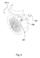
- FIG. 4 shows in more detail the semi-shell 201b, in which the compartment 309 that houses the connector 307 is formed.
- the connector 307 is shown in the drawing to be separate from the semi-shell 201b, thus exposing a second aperture 401 of the second compartment 309.
- Said aperture 401 allows inserting the connector 307, which will be directly plugged onto the capacitor 306 inserted in the compartment 308. In this manner, the electric connection between the connector 307 and the capacitor 306 will be established directly and easily while assembling the suction device 103.
- the aperture 401 allows inserting the connector 307 even when the suction device 103 has already been assembled, as shown by way of example in Figure 2 .
- Said aperture 401 in fact, will remain accessible even after the two semi-shells 201a and 201b have been joined together.
- the particular shape of the connector 307 allows it to be inserted into the aperture 401, since it is designed for resting against a suitable abutment surface visible in Figure 4 .
- the two compartments respectively housing the capacitor and the connector, may be coupled together by means of suitable shape fittings other than the one shown herein.
- the shape of the accessory elements of the volute of the suction device may be different than shown and described herein.
- a suction device may use prior-art teachings as far as materials, construction details, equipment and accessory functions are concerned: all the general aspects of said suction device, whether or not described herein, may therefore vary, provided that they are not in conflict with the teachings of the present invention.
Landscapes
- Engineering & Computer Science (AREA)
- Mechanical Engineering (AREA)
- General Engineering & Computer Science (AREA)
- Chemical & Material Sciences (AREA)
- Combustion & Propulsion (AREA)
- Structures Of Non-Positive Displacement Pumps (AREA)
Abstract
Description
- The present invention relates to the field of hoods, in particular for treating fumes and odours in household environments, e.g. range hoods.
- The invention relates in particular to a suction device for a hood, as well as to an associated range hood.
- Aspirating and/or filtering devices are known which are to be installed near places where fumes or odours are generated. For example, such aspirating and/or filtering devices are called "hoods" and are typically installed in household environments such as kitchens, over burners or cookers or generic heating elements whereon food is cooked.
- Some hoods take in fumes from the environment, discharging the aspirated air into a ventilation duct, which then evacuates both fumes and odours out in the open; such hoods are hence referred to as "extraction hoods".
- Other hoods collect fumes from the environment, filter them, and then reintroduce the air thus purified into the same environment; hoods of this latter type are referred to as "recirculating hoods".
- The hoods known in the art comprise one or more suction devices, typically consisting of a compressor or a fan, wherein an electric motor drives an impeller, which provides an air volume with a certain head, thereby increasing its pressure for moving it within a duct. Known hoods comprise an air inlet opening connected to a chimney-type extraction element, and between the opening and the extraction element the suction device is inserted, which ensures proper operation of the hood.
- Therefore, for the hood to aspirate air, the hoods known in the art require an electric motor for driving the impeller of the suction device.
- For its part, said electric motor requires an appropriate power supply from an electric line; typically, the electric elements associated with electric motors installed in suction devices also comprise connectors and capacitors.
- Such connectors and capacitors, which are needed for properly supplying power to the electric motors, are typically housed inside the suction devices.
- The suction devices known in the art that comprise an electric motor suffer from a number of problems related to the arrangement of these electric elements, such as capacitors and connectors.
- In fact, in some known suction devices, said electric elements are inserted in the volute, in particular under the electric motor.
- In general, the arrangement of said electric elements, such as capacitors and connectors, in the suction devices known in the art results in poor fluid-dynamic performance of the devices themselves, due to the disturbance caused by the air flow taken in by the impeller.
- It is the object of the present invention to overcome some of the problems of the prior art.
- In particular, it is one object of the present invention to provide a suction device which is alternative to those according to the prior art.
- It is another object of the present invention to provide a suction device wherein capacitors and connectors are housed in a position that will not hinder the air flow taken in by the impeller.
- It is another object of the present invention to provide a suction device which can be assembled more easily and manufactured more rationally.
- It is a further object of the present invention to provide a suction device wherein capacitors and connectors are housed in a perfectly safe manner, so as to avoid any risk for the user.
- These and other objects of the present invention are achieved through a suction device and an associated hood incorporating the features set out in the appended claims, which are intended to be an integral part of the present description.
- A basic idea of the present invention is to provide a suction device for a hood, comprising an impeller, an electric motor that drives the impeller, a volute that houses inside the electric motor and the impeller, a capacitor, and a connector electrically connected to the capacitor for supplying power to the motor; the volute comprises a first semi-shell and a second semi-shell joined with each other so as to constitute the structure of the volute surrounding the impeller, and the capacitor is housed in a first compartment formed in the first semi-shell, while the connector is housed in a second compartment formed in the second semi-shell, wherein the first compartment and the second compartment are adjacent to each other in the volute.
- This solution allows realizing a suction device wherein the electric elements, such as the capacitor and its connector, are housed in dedicated compartments, which are advantageously integrated into the semi-shells that constitute the volute. Such an arrangement turns out to be both rational and effective.
- Preferably, the first compartment and the second compartment are located externally to the volute, with respect to the impeller. Thus, the capacitor and its connector are located in a region where they cannot disturb the air flow created by the impeller within the volute.
- Preferably, the suction device further comprises an outflow collar for letting out the air, and the first compartment and the second compartment are located proximal to the outflow collar, above the electric motor. Thus, the capacitor and its connector are located in a region where they cannot disturb the air flow taken in by the impeller outside the volute.
- This allows realizing a suction device offering fully satisfactory fluid-dynamic performance.
- Preferably, the second compartment comprises two apertures in the second semi-shell, and the first compartment comprises only one aperture in the first semi-shell; one aperture of the first compartment faces a respective aperture of the second compartment when the two semi-shells are joined with each other, so as to constitute a common casing for the connector and the capacitor. Thus, the two joined semi-shells form a rational, strong and structurally efficient volute of the suction device.
- Preferably, the connector is inserted into its housing through another aperture between the two apertures of the second semi-shell, which is still accessible when the semi-shells are joined with each other. In this way, it is possible to mount the connector even when the volute has already been assembled and the structure of the suction device is already closed.
- Preferably, on the other hand, the capacitor is inserted through the single aperture of the first semi-shell when the first semi-shell and the second semi-shell have not yet been joined together. This allows mounting the capacitor before assembling the volute, so that it will be placed in a protected and insulated position, thereby improving the electric safety of the suction device and preventing the user from accidentally coming in contact with the capacitor.
- Preferably, both semi-shells are made by moulding of a light and strong plastic material.
- Preferably, the first compartment and the second compartment are formed in one piece in the respective semi-shells, thus further reducing the complexity of the production process and improving the rationality and effectiveness of the structure of the suction device.
- Preferably, the connector is configured to be electrically connected to the capacitor by engaging directly with it, when both are inserted in the second compartment and first compartment, respectively.
- The present invention also relates to an associated range hood in which the above-summarized suction device is installed.
- Further objects and advantages of the present invention will become more apparent from the following detailed description and from the annexed drawings.
- Some preferred and advantageous embodiments will now be described by way of non-limiting example with reference to the annexed drawings, wherein:
-
Figure 1 exemplifies a hood according to the present invention. -
Figure 2 shows a suction device for a hood according to the present invention. -
Figure 3 shows how the suction device of the present invention is assembled. -
Figure 4 shows in detail a connector housed in one of the two semi-shells of the volute. - The drawings show different aspects and embodiments of the present invention and, where appropriate, similar structures, components, materials and/or elements in the various drawings are designated by the same reference numerals.
-
Figure 1 shows one example of arange hood 101 of the extraction type, preferably wall-mounted. In alternative embodiments, the range hood may be, for example, of the "island" type, i.e. installed away from the walls of the room and accessible on all four sides. - The
hood 101 comprises afume collector 102, which is typically positioned above a cooking top; thefume collector 102 may comprise further filter elements (not shown) for filtering airborne greasy particles, consisting of filters in accordance with the teachings of the prior art. - The
hood 101 further comprises asuction device 103, adapted to collect air from thefume collector 102 and direct it into theextraction tube 104, as will be described more in detail below. - Preferably, the
extraction tube 104 is masked by theaesthetic cover 105, which hides it from view to any users in the room where thehood 101 is located. - At the outlet of the
extraction tube 104, i.e. at the top of thehood 101, there is adischarge section 106, such as a wall-mounted flange, which is typically available in the wall of the household environment where thehood 101 is installed. - In general, the present invention is applicable to any type of hood (whether of the extraction or recirculating type) or suction system that includes a suction device, as will be described below.
-
Figure 2 illustrates in more detail thesuction device 103. - The
suction device 103 comprises avolute 201, which houses inside an electric motor and an impeller driven by the electric motor. - The
suction device 103 is configured to take in an air flow from at least onegrid 202 and direct it into theoutflow collar 203. - The
outflow collar 203 is configured to be put in fluidic connection with theextraction tube 104 of thehood 101, while thegrid 202 takes in the air coming from thefume collector 102. The outflow collar (or flange) is typically vertical and directly connected to theextraction tube 104. -
Figure 3 shows the assembly of a preferred embodiment of thesuction device 103. - The
suction device 103 comprises avolute 201, which is made up of twosemi-shells semi-shells - The semi-shells 201a and 201b constitute the structure of the
volute 201 and house anelectric motor 302 and animpeller 303. - The
electric motor 302 is adapted to drive theimpeller 303, which is constrained at its own axis of rotation; as it rotates, theimpeller 303 draws air into thevolute 201 and directs it into theoutflow collar 203. - In general, the
impeller 303 of thesuction device 103 can be designed in many ways understandable by those skilled in the art, in particular as regards the field of centrifugal fans with axial intake. - In the preferred embodiment, the
electric motor 302 has a substantially cylindrical shape. According to a particularly preferred embodiment of theelectric motor 302, said motor is a so-called "S-type" motor. - The
electric motor 302 is of the type that requires a capacitor for receiving electric power, as will be further described below. - The
motor 302 is inserted in thevolute 201, in particular constrained to the semi-shell 201a by means ofscrews 304 fitted into suitable holes in the semi-shell 201a, which engage into respective threaded holes (not shown) of themotor 302. - In addition, the
suction device 103 comprises covering elements such asplugs 305, which electrically insulate thescrews 304 against accidental contact outside thesuction device 103. - The
suction device 103 further comprises acapacitor 306 and aconnector 307, electrically connected to thecapacitor 306, for supplying power to themotor 302. Thus, through theconnector 307, also thecapacitor 306 is electrically connected to themotor 302 for supplying power thereto. - The
capacitor 306 preferably has a substantially cylindrical shape and is housed in thecompartment 308 formed in the semi-shell 201a. - The
connector 307 is housed in thecompartment 309 formed in the semi-shell 201b. - The electric wiring between the
motor 302 and theconnector 307 is not shown in the drawings for the sake of clarity; the drawings can be easily interpreted by those skilled in the art even in the absence of such electric connection elements. - Preferably, the
compartment 308 and thecompartment 309 are formed in one piece, by moulding, in the same semi-shells 201a and 201b, respectively. - As will become apparent when comparing
Figure 2 , which shows thesuction device 103 in the assembled configuration, withFigure 3 , which shows thesuction device 103 in the disassembled configuration, thecompartments volute 201. - In particular, the
compartments volute 201, in particular with respect to theimpeller 303 and also, in particular, to themotor 302. - Preferably, the
compartments outflow collar 203, above the level of themotor 302, when thesuction device 103 is in the position shown. - In particular, the
volute 201 has an asymmetry dictated by the direction of rotation of theimpeller 303, and thecompartments collar 203 because of such asymmetry, thus occupying less room, resulting in a morecompact suction device 103. - The
compartment 308 comprises, in particular, just one aperture, visible inFigure 3 , while it has a blind bottom on the other side, visible inFigure 2 . - The aperture of the
compartment 308 faces a respective aperture of thecompartment 309, hidden at the back of the semi-shell 201b inFigure 4 , so that, when the semi-shells 201a and 201b are joined together, a common casing is formed which houses thecapacitor 306 on one side and theconnector 307 on the other side. - The two semi-shells 201a and 201b are preferably joined to each other by means of a plurality of threaded junctions located at the adjacent edges.
- In this manner, the compartment 308 - once the
volute 201 has been assembled - will be closed; therefore, thecapacitor 306 can only be inserted through the single aperture available while assembling thesuction device 103, when the semi-shells 201a and 201b are still separate. Thecapacitor 306 in thevolute 201 will thus be insulated against accidental mechanical contact and out of the user's reach. -
Figure 4 shows in more detail the semi-shell 201b, in which thecompartment 309 that houses theconnector 307 is formed. For the sake of clarity, theconnector 307 is shown in the drawing to be separate from the semi-shell 201b, thus exposing asecond aperture 401 of thesecond compartment 309. - Said
aperture 401 allows inserting theconnector 307, which will be directly plugged onto thecapacitor 306 inserted in thecompartment 308. In this manner, the electric connection between theconnector 307 and thecapacitor 306 will be established directly and easily while assembling thesuction device 103. - In fact, the
aperture 401 allows inserting theconnector 307 even when thesuction device 103 has already been assembled, as shown by way of example inFigure 2 . Saidaperture 401, in fact, will remain accessible even after the two semi-shells 201a and 201b have been joined together. The particular shape of theconnector 307 allows it to be inserted into theaperture 401, since it is designed for resting against a suitable abutment surface visible inFigure 4 . - It is obvious that, in the light of the teachings of the present description, the man skilled in the art may conceive further variants of the present invention, without however departing from the protection scope as defined by the appended claims.
- For example, the two compartments, respectively housing the capacitor and the connector, may be coupled together by means of suitable shape fittings other than the one shown herein.
- Furthermore, the shape of the accessory elements of the volute of the suction device may be different than shown and described herein.
- In general, the construction details provided merely by way of example in the present description can be modified by the man skilled in the art in accordance with prior-art teachings.
- In particular, a suction device according to the present invention may use prior-art teachings as far as materials, construction details, equipment and accessory functions are concerned: all the general aspects of said suction device, whether or not described herein, may therefore vary, provided that they are not in conflict with the teachings of the present invention.
Claims (10)
- Suction device (103) for a hood, comprising an impeller (303), an electric motor (302) that drives said impeller (303), a volute (201) that houses inside said electric motor (302) and said impeller (303), a capacitor (306), and a connector (307) electrically connected to said capacitor (306) for supplying power to said electric motor (302), characterized in that said volute (201) comprises a first semi-shell (201a) and a second semi-shell (201b) joined with each other so as to constitute the structure of said volute (201) surrounding said impeller (303), said capacitor (306) being housed in a first compartment (308) formed in said first semi-shell (201a), and said connector (307) being housed in a second compartment (309) formed in said second semi-shell (201b), said first compartment (308) and said second compartment (309) being adjacent to each other in said volute (201).
- Suction device according to claim 1, wherein said first compartment (308) and said second compartment (309) are located externally to said volute (201), with respect to said impeller (303).
- Suction device according to claim 1 or 2, further comprising an outflow collar (203), wherein said first compartment (308) and said second compartment (309) are located proximally to said outflow collar (203), above said electric motor (302).
- Suction device according to any one of claims 1 to 3, wherein said second compartment (309) comprises two apertures in said second semi-shell (201b), and wherein said first compartment (308) comprises only one aperture in said first semi-shell (201a), wherein one aperture of said first compartment (308) faces a respective aperture of said second compartment (309) when said first semi-shell (201a) and said second semi-shell (201b) are joined with each other, so as to constitute a common casing (308, 309) for said connector (307) and said capacitor (306).
- Suction device according to claim 4, wherein said connector (307) is inserted through another aperture (401) of said two apertures of said second semi-shell (201b), which is also accessible when said first semi-shell (201a) and said second semi-shell (201b) are joined with each other.
- Suction device according to claim 5, wherein said capacitor (306) is inserted through said only one aperture of said first semi-shell (201a) when said first semi-shell (201a) and said second semi-shell (201b) have not yet been joined together.
- Suction device according to any one of claims 1 to 6, wherein said first semi-shell (201a) and said second semi-shell (201b) are manufactured by moulding of plastic material.
- Suction device according to claim 7, wherein said first compartment (308) and said second compartment (309) are formed in one piece in said first semi-shell (201a) and in said second semi-shell (201b), respectively.
- Suction device according to any one of claims 1 to 8, wherein said connector (307) is configured to connect electrically by engaging directly with said capacitor (306), when both are inserted in said second compartment (309) and in said first compartment (308), respectively.
- Range hood (101), comprising a suction device (103) according to any one of claims 1 to 9.
Applications Claiming Priority (1)
| Application Number | Priority Date | Filing Date | Title |
|---|---|---|---|
| ITTO20141086 | 2014-12-22 |
Publications (2)
| Publication Number | Publication Date |
|---|---|
| EP3037671A1 true EP3037671A1 (en) | 2016-06-29 |
| EP3037671B1 EP3037671B1 (en) | 2019-09-18 |
Family
ID=52597169
Family Applications (1)
| Application Number | Title | Priority Date | Filing Date |
|---|---|---|---|
| EP15199349.0A Active EP3037671B1 (en) | 2014-12-22 | 2015-12-10 | Suction device for a hood, equipped with an electric connector |
Country Status (2)
| Country | Link |
|---|---|
| US (2) | US10273963B2 (en) |
| EP (1) | EP3037671B1 (en) |
Cited By (3)
| Publication number | Priority date | Publication date | Assignee | Title |
|---|---|---|---|---|
| IT201600099345A1 (en) * | 2016-10-04 | 2018-04-04 | E M C Electric Motors Company S R L | FILTERING / VACUUM HOOD TO ASPIRATE AIR IN A KITCHEN. |
| EP4180725A1 (en) * | 2021-11-10 | 2023-05-17 | Berbel Ablufttechnik GmbH | Extractor hood |
| EP4180726A1 (en) * | 2021-11-10 | 2023-05-17 | Berbel Ablufttechnik GmbH | Extractor hood |
Families Citing this family (9)
| Publication number | Priority date | Publication date | Assignee | Title |
|---|---|---|---|---|
| EP3037671B1 (en) | 2014-12-22 | 2019-09-18 | Whirlpool EMEA S.p.A | Suction device for a hood, equipped with an electric connector |
| ITUA20162311A1 (en) * | 2016-04-05 | 2017-10-05 | Elica Spa | Hob with integrated hood. |
| CN108087340A (en) * | 2016-11-21 | 2018-05-29 | 英业达科技有限公司 | Centrifugal fan structure |
| DE102017112983A1 (en) * | 2017-06-13 | 2018-12-13 | Ebm-Papst Mulfingen Gmbh & Co. Kg | Blower housing part with bearing support and blower |
| CN110939954A (en) * | 2018-09-21 | 2020-03-31 | 青岛海尔智能技术研发有限公司 | an integrated stove |
| CN113167294B (en) * | 2018-12-12 | 2023-10-17 | 松下知识产权经营株式会社 | Blower unit and installation structure of the blower unit |
| IT202000016360A1 (en) * | 2020-07-07 | 2022-01-07 | Elica Spa | COOKTOP WITH EXTRACTOR HOOD |
| CN112377428B (en) * | 2020-10-30 | 2021-11-26 | 宁波方太厨具有限公司 | Fan system, range hood applying fan system and installation method of range hood |
| US11962220B2 (en) * | 2021-12-10 | 2024-04-16 | Corsair Memory, Inc. | Smart-fan components, controls and systems |
Citations (2)
| Publication number | Priority date | Publication date | Assignee | Title |
|---|---|---|---|---|
| EP0985829A2 (en) * | 1998-09-11 | 2000-03-15 | ebm Werke GmbH & Co. | Housing for radial blower |
| EP1094224A2 (en) * | 1999-10-19 | 2001-04-25 | ebm Werke GmbH & Co. KG | Radial fan |
Family Cites Families (23)
| Publication number | Priority date | Publication date | Assignee | Title |
|---|---|---|---|---|
| US2895666A (en) * | 1956-07-17 | 1959-07-21 | Leland Electric Canada Ltd | External rotor motor fan assembly |
| US2971451A (en) * | 1958-06-16 | 1961-02-14 | Progress Mfg Company | Ventilator unit |
| US3300122A (en) * | 1963-04-18 | 1967-01-24 | Andrew D Bowles | Ventilator |
| US3563004A (en) * | 1968-10-29 | 1971-02-16 | Anpol Research Corp | Separator structure |
| US4447859A (en) * | 1982-11-26 | 1984-05-08 | Inverse Square Systems Incorporated | Modular flash system |
| US5141397A (en) * | 1991-01-18 | 1992-08-25 | Sullivan John T | Volute housing for a centrifugal fan, blower or the like |
| US5285113A (en) * | 1991-06-17 | 1994-02-08 | Remarkable Products, Inc. | Circuit control apparatus for boat trailers |
| KR100363458B1 (en) * | 1994-05-18 | 2003-03-26 | 후지 샤신 필름 가부시기가이샤 | Lens-mounted photographic film unit and flash unit for use in it |
| US5997246A (en) * | 1998-04-02 | 1999-12-07 | Ford Motor Company | Housing for a centrifugal blower |
| US6223741B1 (en) * | 2000-02-24 | 2001-05-01 | Mihail Panos | Residential-type stove hood with fluid filter cleaning means |
| US6511288B1 (en) * | 2000-08-30 | 2003-01-28 | Jakel Incorporated | Two piece blower housing with vibration absorbing bottom piece and mounting flanges |
| US6386123B1 (en) * | 2000-08-30 | 2002-05-14 | Jakel Incorporated | Blower housing with maximized interior spacing |
| US7278823B2 (en) * | 2004-09-03 | 2007-10-09 | Fasco Industries, Inc. | Draft inducer blower |
| DE102005034659B3 (en) * | 2005-07-25 | 2007-04-12 | Lenze Drive Systems Gmbh | Holding device for a cup capacitor |
| US7861708B1 (en) * | 2006-02-03 | 2011-01-04 | Fasco Industries, Inc. | Draft inducer blower mounting feature which reduces overall system vibration |
| ES2607841T3 (en) * | 2009-03-25 | 2017-04-04 | Ebm-Papst Mulfingen Gmbh & Co. Kg | Radial fan |
| DE202009017511U1 (en) * | 2009-12-22 | 2011-05-05 | Ebm-Pabst Mulfingen Gmbh & Co. Kg | Fan unit for filter fan |
| US10137264B2 (en) * | 2011-07-13 | 2018-11-27 | Fisher & Paykel Healthcare Limited | Respiratory assistance apparatus |
| US9360198B2 (en) * | 2011-12-06 | 2016-06-07 | Express Imaging Systems, Llc | Adjustable output solid-state lighting device |
| JP6108590B2 (en) * | 2012-01-17 | 2017-04-05 | アスモ株式会社 | Electric pump |
| US10113550B2 (en) * | 2012-08-28 | 2018-10-30 | Broan-Nutone Llc | Ventilation system and method |
| US9680269B2 (en) * | 2013-08-08 | 2017-06-13 | Lennox Industries Inc. | Electrical contactor with header connectors |
| EP3037671B1 (en) * | 2014-12-22 | 2019-09-18 | Whirlpool EMEA S.p.A | Suction device for a hood, equipped with an electric connector |
-
2015
- 2015-12-10 EP EP15199349.0A patent/EP3037671B1/en active Active
- 2015-12-17 US US14/972,632 patent/US10273963B2/en not_active Expired - Fee Related
-
2019
- 2019-04-02 US US16/372,601 patent/US10704557B2/en not_active Expired - Fee Related
Patent Citations (2)
| Publication number | Priority date | Publication date | Assignee | Title |
|---|---|---|---|---|
| EP0985829A2 (en) * | 1998-09-11 | 2000-03-15 | ebm Werke GmbH & Co. | Housing for radial blower |
| EP1094224A2 (en) * | 1999-10-19 | 2001-04-25 | ebm Werke GmbH & Co. KG | Radial fan |
Cited By (3)
| Publication number | Priority date | Publication date | Assignee | Title |
|---|---|---|---|---|
| IT201600099345A1 (en) * | 2016-10-04 | 2018-04-04 | E M C Electric Motors Company S R L | FILTERING / VACUUM HOOD TO ASPIRATE AIR IN A KITCHEN. |
| EP4180725A1 (en) * | 2021-11-10 | 2023-05-17 | Berbel Ablufttechnik GmbH | Extractor hood |
| EP4180726A1 (en) * | 2021-11-10 | 2023-05-17 | Berbel Ablufttechnik GmbH | Extractor hood |
Also Published As
| Publication number | Publication date |
|---|---|
| US20160177957A1 (en) | 2016-06-23 |
| US20190226487A1 (en) | 2019-07-25 |
| US10273963B2 (en) | 2019-04-30 |
| EP3037671B1 (en) | 2019-09-18 |
| US10704557B2 (en) | 2020-07-07 |
Similar Documents
| Publication | Publication Date | Title |
|---|---|---|
| US10704557B2 (en) | Suction device for a range hood comprising a volute including a first semi-shell and a second semi-shell forming a compartment for housing a capacitor and a connector electrically coupled to an electric motor | |
| EP3037672B1 (en) | Adapter in a suction device for a hood | |
| US10900665B2 (en) | Combination appliance having a cooktop and steam extraction device | |
| EP2865950B1 (en) | Modular vent hood blower kit for in-line or external application | |
| US10712019B2 (en) | Combined device with cooking surface and fume extractor | |
| JP6790247B2 (en) | Ventilation device with air intake | |
| CN108885012A (en) | Hob with integrated hood | |
| US12618568B2 (en) | Cooking hob with extractor hood | |
| CN109642736B (en) | Kitchen range | |
| CN107894014B (en) | Heating cooker | |
| KR102921985B1 (en) | Mobile recirculating grill with plenum and diffuser | |
| US9992823B2 (en) | Over-the-range microwave oven with an integrated duct | |
| CN111810994A (en) | Home Appliances & Cooking Systems | |
| CN219048123U (en) | Multifunctional pot | |
| EP4043798B1 (en) | Combination appliance and method for assembling the same | |
| CN110650616B (en) | Highly efficient heat dissipation protection structure and household appliances | |
| EP4006433A1 (en) | Extraction device and method for assembling a ventilation system | |
| EP3488151A1 (en) | A cooktop | |
| ITAN20120001U1 (en) | SUCTION COOKER TOP | |
| ITMC20120093A1 (en) | PERFECTED ASPIRATING HOOD. | |
| EP2607796A1 (en) | Direct drive ventilation cooker hood | |
| ITAN20120167A1 (en) | PERFECTED ASPIRATING HOOD. | |
| IT201600099345A1 (en) | FILTERING / VACUUM HOOD TO ASPIRATE AIR IN A KITCHEN. | |
| KR20140104750A (en) | Noise protecting hood |
Legal Events
| Date | Code | Title | Description |
|---|---|---|---|
| PUAI | Public reference made under article 153(3) epc to a published international application that has entered the european phase |
Free format text: ORIGINAL CODE: 0009012 |
|
| AK | Designated contracting states |
Kind code of ref document: A1 Designated state(s): AL AT BE BG CH CY CZ DE DK EE ES FI FR GB GR HR HU IE IS IT LI LT LU LV MC MK MT NL NO PL PT RO RS SE SI SK SM TR |
|
| AX | Request for extension of the european patent |
Extension state: BA ME |
|
| STAA | Information on the status of an ep patent application or granted ep patent |
Free format text: STATUS: REQUEST FOR EXAMINATION WAS MADE |
|
| 17P | Request for examination filed |
Effective date: 20161219 |
|
| RBV | Designated contracting states (corrected) |
Designated state(s): AL AT BE BG CH CY CZ DE DK EE ES FI FR GB GR HR HU IE IS IT LI LT LU LV MC MK MT NL NO PL PT RO RS SE SI SK SM TR |
|
| RAP1 | Party data changed (applicant data changed or rights of an application transferred) |
Owner name: WHIRLPOOL EMEA S.P.A |
|
| GRAP | Despatch of communication of intention to grant a patent |
Free format text: ORIGINAL CODE: EPIDOSNIGR1 |
|
| STAA | Information on the status of an ep patent application or granted ep patent |
Free format text: STATUS: GRANT OF PATENT IS INTENDED |
|
| RIC1 | Information provided on ipc code assigned before grant |
Ipc: F04D 29/62 20060101ALI20190614BHEP Ipc: F24C 15/20 20060101ALI20190614BHEP Ipc: F04D 25/08 20060101ALI20190614BHEP Ipc: F04D 25/06 20060101AFI20190614BHEP Ipc: F04D 29/42 20060101ALI20190614BHEP |
|
| INTG | Intention to grant announced |
Effective date: 20190702 |
|
| GRAS | Grant fee paid |
Free format text: ORIGINAL CODE: EPIDOSNIGR3 |
|
| GRAA | (expected) grant |
Free format text: ORIGINAL CODE: 0009210 |
|
| STAA | Information on the status of an ep patent application or granted ep patent |
Free format text: STATUS: THE PATENT HAS BEEN GRANTED |
|
| AK | Designated contracting states |
Kind code of ref document: B1 Designated state(s): AL AT BE BG CH CY CZ DE DK EE ES FI FR GB GR HR HU IE IS IT LI LT LU LV MC MK MT NL NO PL PT RO RS SE SI SK SM TR |
|
| REG | Reference to a national code |
Ref country code: GB Ref legal event code: FG4D |
|
| REG | Reference to a national code |
Ref country code: CH Ref legal event code: EP |
|
| REG | Reference to a national code |
Ref country code: DE Ref legal event code: R096 Ref document number: 602015038151 Country of ref document: DE |
|
| REG | Reference to a national code |
Ref country code: AT Ref legal event code: REF Ref document number: 1181637 Country of ref document: AT Kind code of ref document: T Effective date: 20191015 |
|
| REG | Reference to a national code |
Ref country code: IE Ref legal event code: FG4D |
|
| REG | Reference to a national code |
Ref country code: NL Ref legal event code: MP Effective date: 20190918 |
|
| PG25 | Lapsed in a contracting state [announced via postgrant information from national office to epo] |
Ref country code: HR Free format text: LAPSE BECAUSE OF FAILURE TO SUBMIT A TRANSLATION OF THE DESCRIPTION OR TO PAY THE FEE WITHIN THE PRESCRIBED TIME-LIMIT Effective date: 20190918 Ref country code: SE Free format text: LAPSE BECAUSE OF FAILURE TO SUBMIT A TRANSLATION OF THE DESCRIPTION OR TO PAY THE FEE WITHIN THE PRESCRIBED TIME-LIMIT Effective date: 20190918 Ref country code: BG Free format text: LAPSE BECAUSE OF FAILURE TO SUBMIT A TRANSLATION OF THE DESCRIPTION OR TO PAY THE FEE WITHIN THE PRESCRIBED TIME-LIMIT Effective date: 20191218 Ref country code: LT Free format text: LAPSE BECAUSE OF FAILURE TO SUBMIT A TRANSLATION OF THE DESCRIPTION OR TO PAY THE FEE WITHIN THE PRESCRIBED TIME-LIMIT Effective date: 20190918 Ref country code: FI Free format text: LAPSE BECAUSE OF FAILURE TO SUBMIT A TRANSLATION OF THE DESCRIPTION OR TO PAY THE FEE WITHIN THE PRESCRIBED TIME-LIMIT Effective date: 20190918 Ref country code: NO Free format text: LAPSE BECAUSE OF FAILURE TO SUBMIT A TRANSLATION OF THE DESCRIPTION OR TO PAY THE FEE WITHIN THE PRESCRIBED TIME-LIMIT Effective date: 20191218 |
|
| REG | Reference to a national code |
Ref country code: LT Ref legal event code: MG4D |
|
| PG25 | Lapsed in a contracting state [announced via postgrant information from national office to epo] |
Ref country code: RS Free format text: LAPSE BECAUSE OF FAILURE TO SUBMIT A TRANSLATION OF THE DESCRIPTION OR TO PAY THE FEE WITHIN THE PRESCRIBED TIME-LIMIT Effective date: 20190918 Ref country code: GR Free format text: LAPSE BECAUSE OF FAILURE TO SUBMIT A TRANSLATION OF THE DESCRIPTION OR TO PAY THE FEE WITHIN THE PRESCRIBED TIME-LIMIT Effective date: 20191219 Ref country code: AL Free format text: LAPSE BECAUSE OF FAILURE TO SUBMIT A TRANSLATION OF THE DESCRIPTION OR TO PAY THE FEE WITHIN THE PRESCRIBED TIME-LIMIT Effective date: 20190918 Ref country code: LV Free format text: LAPSE BECAUSE OF FAILURE TO SUBMIT A TRANSLATION OF THE DESCRIPTION OR TO PAY THE FEE WITHIN THE PRESCRIBED TIME-LIMIT Effective date: 20190918 |
|
| REG | Reference to a national code |
Ref country code: AT Ref legal event code: MK05 Ref document number: 1181637 Country of ref document: AT Kind code of ref document: T Effective date: 20190918 |
|
| PG25 | Lapsed in a contracting state [announced via postgrant information from national office to epo] |
Ref country code: PT Free format text: LAPSE BECAUSE OF FAILURE TO SUBMIT A TRANSLATION OF THE DESCRIPTION OR TO PAY THE FEE WITHIN THE PRESCRIBED TIME-LIMIT Effective date: 20200120 Ref country code: ES Free format text: LAPSE BECAUSE OF FAILURE TO SUBMIT A TRANSLATION OF THE DESCRIPTION OR TO PAY THE FEE WITHIN THE PRESCRIBED TIME-LIMIT Effective date: 20190918 Ref country code: NL Free format text: LAPSE BECAUSE OF FAILURE TO SUBMIT A TRANSLATION OF THE DESCRIPTION OR TO PAY THE FEE WITHIN THE PRESCRIBED TIME-LIMIT Effective date: 20190918 Ref country code: AT Free format text: LAPSE BECAUSE OF FAILURE TO SUBMIT A TRANSLATION OF THE DESCRIPTION OR TO PAY THE FEE WITHIN THE PRESCRIBED TIME-LIMIT Effective date: 20190918 Ref country code: EE Free format text: LAPSE BECAUSE OF FAILURE TO SUBMIT A TRANSLATION OF THE DESCRIPTION OR TO PAY THE FEE WITHIN THE PRESCRIBED TIME-LIMIT Effective date: 20190918 Ref country code: RO Free format text: LAPSE BECAUSE OF FAILURE TO SUBMIT A TRANSLATION OF THE DESCRIPTION OR TO PAY THE FEE WITHIN THE PRESCRIBED TIME-LIMIT Effective date: 20190918 Ref country code: PL Free format text: LAPSE BECAUSE OF FAILURE TO SUBMIT A TRANSLATION OF THE DESCRIPTION OR TO PAY THE FEE WITHIN THE PRESCRIBED TIME-LIMIT Effective date: 20190918 |
|
| PG25 | Lapsed in a contracting state [announced via postgrant information from national office to epo] |
Ref country code: SM Free format text: LAPSE BECAUSE OF FAILURE TO SUBMIT A TRANSLATION OF THE DESCRIPTION OR TO PAY THE FEE WITHIN THE PRESCRIBED TIME-LIMIT Effective date: 20190918 Ref country code: IS Free format text: LAPSE BECAUSE OF FAILURE TO SUBMIT A TRANSLATION OF THE DESCRIPTION OR TO PAY THE FEE WITHIN THE PRESCRIBED TIME-LIMIT Effective date: 20200224 Ref country code: SK Free format text: LAPSE BECAUSE OF FAILURE TO SUBMIT A TRANSLATION OF THE DESCRIPTION OR TO PAY THE FEE WITHIN THE PRESCRIBED TIME-LIMIT Effective date: 20190918 Ref country code: CZ Free format text: LAPSE BECAUSE OF FAILURE TO SUBMIT A TRANSLATION OF THE DESCRIPTION OR TO PAY THE FEE WITHIN THE PRESCRIBED TIME-LIMIT Effective date: 20190918 |
|
| REG | Reference to a national code |
Ref country code: DE Ref legal event code: R097 Ref document number: 602015038151 Country of ref document: DE |
|
| PLBE | No opposition filed within time limit |
Free format text: ORIGINAL CODE: 0009261 |
|
| STAA | Information on the status of an ep patent application or granted ep patent |
Free format text: STATUS: NO OPPOSITION FILED WITHIN TIME LIMIT |
|
| PG2D | Information on lapse in contracting state deleted |
Ref country code: IS |
|
| PG25 | Lapsed in a contracting state [announced via postgrant information from national office to epo] |
Ref country code: DK Free format text: LAPSE BECAUSE OF FAILURE TO SUBMIT A TRANSLATION OF THE DESCRIPTION OR TO PAY THE FEE WITHIN THE PRESCRIBED TIME-LIMIT Effective date: 20190918 Ref country code: IS Free format text: LAPSE BECAUSE OF FAILURE TO SUBMIT A TRANSLATION OF THE DESCRIPTION OR TO PAY THE FEE WITHIN THE PRESCRIBED TIME-LIMIT Effective date: 20200119 |
|
| REG | Reference to a national code |
Ref country code: CH Ref legal event code: PL |
|
| 26N | No opposition filed |
Effective date: 20200619 |
|
| REG | Reference to a national code |
Ref country code: BE Ref legal event code: MM Effective date: 20191231 |
|
| PG25 | Lapsed in a contracting state [announced via postgrant information from national office to epo] |
Ref country code: SI Free format text: LAPSE BECAUSE OF FAILURE TO SUBMIT A TRANSLATION OF THE DESCRIPTION OR TO PAY THE FEE WITHIN THE PRESCRIBED TIME-LIMIT Effective date: 20190918 Ref country code: MC Free format text: LAPSE BECAUSE OF FAILURE TO SUBMIT A TRANSLATION OF THE DESCRIPTION OR TO PAY THE FEE WITHIN THE PRESCRIBED TIME-LIMIT Effective date: 20190918 |
|
| PG25 | Lapsed in a contracting state [announced via postgrant information from national office to epo] |
Ref country code: IE Free format text: LAPSE BECAUSE OF NON-PAYMENT OF DUE FEES Effective date: 20191210 Ref country code: LU Free format text: LAPSE BECAUSE OF NON-PAYMENT OF DUE FEES Effective date: 20191210 |
|
| PG25 | Lapsed in a contracting state [announced via postgrant information from national office to epo] |
Ref country code: CH Free format text: LAPSE BECAUSE OF NON-PAYMENT OF DUE FEES Effective date: 20191231 Ref country code: LI Free format text: LAPSE BECAUSE OF NON-PAYMENT OF DUE FEES Effective date: 20191231 Ref country code: BE Free format text: LAPSE BECAUSE OF NON-PAYMENT OF DUE FEES Effective date: 20191231 |
|
| PG25 | Lapsed in a contracting state [announced via postgrant information from national office to epo] |
Ref country code: CY Free format text: LAPSE BECAUSE OF FAILURE TO SUBMIT A TRANSLATION OF THE DESCRIPTION OR TO PAY THE FEE WITHIN THE PRESCRIBED TIME-LIMIT Effective date: 20190918 |
|
| PG25 | Lapsed in a contracting state [announced via postgrant information from national office to epo] |
Ref country code: HU Free format text: LAPSE BECAUSE OF FAILURE TO SUBMIT A TRANSLATION OF THE DESCRIPTION OR TO PAY THE FEE WITHIN THE PRESCRIBED TIME-LIMIT; INVALID AB INITIO Effective date: 20151210 Ref country code: MT Free format text: LAPSE BECAUSE OF FAILURE TO SUBMIT A TRANSLATION OF THE DESCRIPTION OR TO PAY THE FEE WITHIN THE PRESCRIBED TIME-LIMIT Effective date: 20190918 |
|
| PG25 | Lapsed in a contracting state [announced via postgrant information from national office to epo] |
Ref country code: TR Free format text: LAPSE BECAUSE OF FAILURE TO SUBMIT A TRANSLATION OF THE DESCRIPTION OR TO PAY THE FEE WITHIN THE PRESCRIBED TIME-LIMIT Effective date: 20190918 |
|
| PG25 | Lapsed in a contracting state [announced via postgrant information from national office to epo] |
Ref country code: MK Free format text: LAPSE BECAUSE OF FAILURE TO SUBMIT A TRANSLATION OF THE DESCRIPTION OR TO PAY THE FEE WITHIN THE PRESCRIBED TIME-LIMIT Effective date: 20190918 |
|
| P01 | Opt-out of the competence of the unified patent court (upc) registered |
Effective date: 20230523 |
|
| REG | Reference to a national code |
Ref country code: DE Ref legal event code: R081 Ref document number: 602015038151 Country of ref document: DE Owner name: WHIRLPOOL EMEA S.R.L., IT Free format text: FORMER OWNER: WHIRLPOOL EMEA S.P.A, PERO, IT |
|
| PGFP | Annual fee paid to national office [announced via postgrant information from national office to epo] |
Ref country code: GB Payment date: 20251223 Year of fee payment: 11 |
|
| PGFP | Annual fee paid to national office [announced via postgrant information from national office to epo] |
Ref country code: IT Payment date: 20251205 Year of fee payment: 11 |
|
| PGFP | Annual fee paid to national office [announced via postgrant information from national office to epo] |
Ref country code: FR Payment date: 20251223 Year of fee payment: 11 |
|
| PGFP | Annual fee paid to national office [announced via postgrant information from national office to epo] |
Ref country code: DE Payment date: 20251229 Year of fee payment: 11 |