EP3037594B1 - Lavatory systems - Google Patents
Lavatory systems Download PDFInfo
- Publication number
- EP3037594B1 EP3037594B1 EP16020001.0A EP16020001A EP3037594B1 EP 3037594 B1 EP3037594 B1 EP 3037594B1 EP 16020001 A EP16020001 A EP 16020001A EP 3037594 B1 EP3037594 B1 EP 3037594B1
- Authority
- EP
- European Patent Office
- Prior art keywords
- lavatory
- housing
- outlet
- air
- urinal
- Prior art date
- Legal status (The legal status is an assumption and is not a legal conclusion. Google has not performed a legal analysis and makes no representation as to the accuracy of the status listed.)
- Active
Links
Images




Classifications
-
- E—FIXED CONSTRUCTIONS
- E03—WATER SUPPLY; SEWERAGE
- E03D—WATER-CLOSETS OR URINALS WITH FLUSHING DEVICES; FLUSHING VALVES THEREFOR
- E03D9/00—Sanitary or other accessories for lavatories ; Devices for cleaning or disinfecting the toilet room or the toilet bowl; Devices for eliminating smells
- E03D9/04—Special arrangement or operation of ventilating devices
- E03D9/05—Special arrangement or operation of ventilating devices ventilating the bowl
- E03D9/052—Special arrangement or operation of ventilating devices ventilating the bowl using incorporated fans
Definitions
- This disclosure relates to lavatory installations and extraction systems.
- US 2007/0189891 of Herbst et al discloses a two-part fan housing for a centrifugal fan with an axial inlet opening in a fan housing cover that fits onto what may be regarded as a front face of the larger portion of the fan housing. Air is received axially of the fan and is directed tangentially to an outlet. The rearmost portion of the housing furthest from the front face is provided by a portion of the impeller housing, the diameter of which is substantially less than the depth of the housing from that portion of the impeller housing to the front face.
- European Patent Application No: 09769573.8 (published as WO2009/156732 ), from which the present Application has been divided, was concerned with an extraction system for a lavatory unit selected from urinals and toilet bowls, the lavatory unit including a receptacle for human liquid or solid waste, the receptacle having an outlet for such waste; the extraction system being adapted to extract odours from a region upstream of the receptacle outlet, and comprising: a shallow housing having front and rear walls and side walls interconnecting the front and rear walls, the depth of the housing from the front to the rear wall being substantially less than distances across the front and rear walls from one side to the other thereof, the housing mounting a centrifugal fan with its axis perpendicular to the rear wall, the fan having an axial air inlet located centrally of the front wall and an air outlet generally tangential to the fan in a side wall of the housing, the housing being adapted for mounting with a ducting
- the housing is may be provided with two ducting connections, namely a first connection from a region of the lavatory unit upstream of the water trap to the air inlet and a second connection from the air outlet to the lavatory unit downstream of the water trap.
- European Patent Application No: 09769573.8 was concerned with an extraction system for a lavatory unit, selected from urinals and toilet bowls, of the kind including a water trap; the extractor system being adapted to extract odours from a region upstream of the water trap, and comprising: a shallow housing having front and rear walls and side walls interconnecting the front and rear walls, the depth of the housing from the front to the rear wall being substantially less than distances across the front and rear walls from one side to the other thereof, the housing mounting a centrifugal fan with its axis perpendicular to the rear wall, the fan having an axial inlet located centrally of the front wall and an outlet generally tangential to the fan in a side wall of the housing, the housing being adapted for mounting with a ducting connection from a region of the lavatory unit upstream of the water trap to the inlet and a ducting connection from the outlet to the lavatory unit downstream of the water trap.
- an extraction system suitable for removing unpleasant lavatory odour from a lavatory room, for example a public lavatory, having at least one lavatory unit comprising a receptacle for receiving human liquid or solid waste and having an outlet for such waste; the extraction system being adapted to remove odour from air within the lavatory room at a position upstream of said waste outlet, and being characterised in comprising: a shallow housing having front and rear walls and side walls interconnecting the front and rear walls, the depth of the housing from the front to the rear wall being substantially less than all distances across the front and rear walls from one side to the other thereof, the housing mounting a centrifugal fan with its axis perpendicular to the rear wall, the fan having an axial air inlet located centrally of the front wall for receiving odour-laden air emanating from said lavatory unit on the upstream side of the said waste outlet, and an air outlet from the fan generally tangential to the fan
- a ducting connection may be provided from a region upstream of the water trap to the inlet.
- a lavatory installation comprising a lavatory unit and an extraction system as aforesaid, wherein the rear wall of the housing is mounted to a generally vertical surface selected from a building wall associated with the installation and an internal surface of a water cistern.
- the housing may be mounted to a preferably generally vertical surface internally of the cistern above the maximum water level thereof.
- a ducting connection comprising a pipe or hose coupled may be provided from a region of the toilet bowl adjacent its rim to the inlet.
- the cistern may have a flushing mechanism with a built-in overflow into the toilet bowl and a cistern lid with a seal, the inlet being open to the interior of the cistern above its water line, and the ducting connection to the inlet may comprise the said built-in overflow.
- the housing may be mounted to a wall alongside the urinal bowl, and a ducting connection may be provided to the air inlet, the ducting connection comprising piping tapping into plumbing for the urinal unit downstream of the outlet from the urinal bowl, and immediately above its water trap, where the urinal is fitted with a water trap, airflow of odour laden air to the inlet being via that outlet, the said plumbing and the ducting connection to the air inlet.
- the lavatory unit comprises a urinal of the kind comprising a trough in which urine is collected before passing via an outlet comprising a drain from the trough and a water trap to a waste pipe
- the housing may be mounted to a wall, and a ducting connection may be provided to the air inlet comprising piping tapping into plumbing for the urinal between the drain and the water trap.
- a shallow housing 1 for a centrifugal fan 2 is shown in Figs. 1 and 2 .
- the housing comprises a front wall 3 and a rear wall 4.
- Centrifugal fan 2 is preferably a radial blower. Suitable 12 volt DC radial blowers with electronically commutated external rotor motor are available from ebm-papst UK Ltd of Chelmsford, Essex under the trade designation REF 100-11/12, and have a total thickness of fan and motor of under 25mm.
- the motor of fan 2 is mounted by screws to mounts 5 on rear wall 4.
- An inlet stub pipe 6 is mounted centrally of front wall 3 via a frustoconical portion 7 to define plenum 8 for inlet air on the inlet side of fan 2.
- the fan draws air in axially and ejects it in a tangential direction.
- the fan blades are preferably backwardly curved to reduce noise and increase efficiency.
- Side walls 9 extending perpendicular to the front wall extend from each edge of front wall 1 towards the rear wall.
- An interior wall 10 is mounted within a chamber effectively defined by the front wall and side walls to guide air flow towards an outlet stub pipe 11 mounted in one side wall. It will be seen that interior wall 10 follows the cylindrical profile of the fan at a fixed radial separation over three-quarters of a circumference before diverging to outlet 11.
- Front wall 3 is generally square apart from three of its four corners, which are cut-away. As best shown in the scrap sectional view of Fig.
- apertured triangular flanges 12 are mounted to side walls 9 at their edges furthest from front wall 3 at positions corresponding to the cut-away corners.
- the main portion 13 of housing 1, comprising the front wall with its sidewalls, the flanges and the interior wall may be moulded, for example from acrylic plastics, in one piece.
- Rear wall 4 forms a complete square with apertured corners corresponding to the positions of apertured flanges 12.
- a shallow upstanding wall 14 is integrally formed on rear wall 4, again by moulding the rear wall 4 in one piece, at positions just in board of the positions occupied by sidewalls 9 when the main portion 13 is offered up to rear wall 4 already mounting the fan 2 and motor.
- Fixings inserted through the apertures in flanges 12 and rear wall 4 enable the fan and its housing 1 to be mounted to a generally vertical surface.
- the depth of the housing from the front to the rear wall is substantially less than distances across the front and rear walls from one side to the other.
- a urinal 15 comprises a urinal basin 16 with a drain 17 from which urine, together with water used periodically to flush the urinal basin, passes via a conventional water trap 18 to a waste pipe 19.
- Urinal basin 16 will generally be mounted to a vertical wall.
- a housing 1 with fan 2 and motor is conveniently mounted alongside urinal basin 16 on the same wall.
- Ducting 20 is provided between a region upstream of the water trap and inlet 6 of housing 1.
- the ducting 20 here comprises piping tapped into the plumbing for the urinal unit below drain 17 immediately above its water trap 18.
- Ducting 21 connects outlet 11 with waste pipe 19 downstream of water trap 18.
- valve 22 comprises a generally cubic housing 23 defining a valve chamber 24 therewithin.
- Two stub pipes 25, 26 are coupled to housing 23.
- One stub pipe 25 is simply joined to one wall 27 of housing 23.
- the other penetrates through a wall 28 of the housing 23 opposite wall 27, its end 29 being cut at an angle.
- a flap valve 30 is pivoted at 31 so as to overlie cut end 29 by gravity. Air pressure created by fan 2 is sufficient to open flap valve 30 to allow odour-laden air to pass. When the motor stops, the flap valve will close cut end 29 preventing back flushing of sewer gas.
- the system illustrated in Fig. 4 has the advantage that air extraction is applied to the region in which the odour is generated, so that significantly less power is consumed as compared with an extraction system seeking to reduce odour by ventilating the lavatory room as a whole.
- a typical motor for fan 2 has a consumption of 7.5 watts/hour.
- the extraction system illustrated in Fig. 4 may be applied equally well to a urinal of the kind comprising a trough in which urine is collected before passing via a drain from the trough and a water trap to a waste pipe.
- housing 1 would be mounted to a convenient wall, the ducting connection to the inlet 6 comprising piping tapping into plumbing for the urinal between its drain and its water trap, and the ducting connection from the outlet 11 comprises piping coupling the outlet 11 to the said waste pipe downstream of the water trap.
- Similar odour-reducing extraction may be applied to the toilet bowl of a water closet, as explained with reference to Figs. 6 and 7 .
- a water closet 32 is schematically illustrated in Fig. 6 and comprises a toilet bowl 33 with an outlet 34 to a conventional S-bend water trap exiting into a soil pipe 35.
- Toilet bowl 33 is flushed from a water cistern 36 by a flushing mechanism, indicated schematically at 37, which may be operated mechanically by a user (lever, press-button, etc) in conventional fashion or under automatic control (for example a proximity detector) again in a manner known per se, and is typically lifted to allow water within the cistern to pass through an opening into a conventional down pipe 38 issuing into toilet bowl 33
- Cistern 36 has a water feed 39 from an external source controlled by a float valve 40, here a conventional ball-cock 41, which sets a maximum water level in the cistern.
- the flushing mechanism 37 here includes a built-in overflow 42 into the toilet bowl 33 via the normal flushing down pipe 38.
- the cistern 36 has a cistern lid 43 with a seal 44.
- the housing 1, with fan 2 and motor is mounted to a generally vertical surface 45 internally of the cistern 36 above the maximum water level thereof.
- the inlet 6 is simply open to the air space above the water level in the cistern.
- the outlet 11 is coupled via piping 46 and a non-return valve 22 to soil pipe 35 downstream of the S-bend.
- Operation of the extractor unit creates a partial vacuum within the cistern drawing odour-laden air from the toilet bowl via ducting provided by the down pipe 38 and overflow pipe 42 into the airspace above the water line within the cistern and hence to inlet 6, the odour-laden air being exhausted via piping 46 to the soil pipe.
- a housing 1 within the cistern 36 may be coupled by a separate pipe from the toilet bowl adjacent its rim to inlet 6.
- housing 1 is mounted alongside cistern 36, inlet 6 being coupled to the air space above the water level in the cistern via a pipe 47 through the wall of the cistern.
- toilet bowl systems may be set to operate only intermittently, for example by the motor being switched on for a set period from each operation of the flushing mechanism to exhaust odour-laden air from the bowl.
- a suitable 12 volt transformer/adaptor 48 may be mounted at a convenient position and coupled to the mains power supply, wiring 49 providing DC power to the motor. With in-cistern installation of the housing 1, wiring 50 from transformer/adaptor 48 is conveniently fed into cistern 36 via piping 46 and outlet 11, as shown in Fig. 6 .
- the housing may simply be fitted to, and supported by, the ducting.
- the apertured flanges 12 may be omitted.
- a shallow housing 1 for a centrifugal fan (not shown, but identically mounted to the fan of Figs. 1 to 3 ) comprises a front wall 3 and a rear wall 4.
- An air inlet stub pipe 6 is mounted centrally of front wall 3 via a frustoconical portion 7 to define plenum 8 for inlet air on the inlet side of the fan.
- the fan draws air in axially and ejects it in a tangential direction.
- Side walls 9 extending perpendicular to the front wall extend from each edge of front wall 1 towards the rear wall. Rather than being provided with an outlet stub pipe serving as an air outlet, as in the embodiment of Figs.
- tangentially driven air from the centrifugal fan issues into an absorbent filter unit 101, 102 comprising an absorbent mass 101 contained within a filter housing 102 defined between extended portions 103 and 104 of the front and rear walls 3 and 4.
- filtered air is discharged to atmosphere through a grille 105 formed in the extended top wall 103.
- Absorbent mass 101 is a carbon filter.
- the carbon filter is provided in the form of a replaceable filter cartridge 106, as illustrated, in which the filter mass 101 is mounted to an end wall 107 fitted with a tab 108. When the filter mass is full, a user may simply withdraw the cartridge from the housing 102 by pulling on tab 108.
- the cartridge can be regenerated by heating to drive off the trapped odour molecules, and can then be re-used.
- a perfume source 109 to scent air d to atmosphere from the absorbent filter unit is provided.
- Cartridge 109 may contain the perfume.
- the extraction system may be mounted to urinals or lavatories in all the ways described and illustrated in Figs. 4 , 6 and 7 .
Landscapes
- Health & Medical Sciences (AREA)
- Public Health (AREA)
- Epidemiology (AREA)
- Life Sciences & Earth Sciences (AREA)
- Engineering & Computer Science (AREA)
- Hydrology & Water Resources (AREA)
- Water Supply & Treatment (AREA)
- Sanitary Device For Flush Toilet (AREA)
Description
- This disclosure relates to lavatory installations and extraction systems.
- Unpleasant odours are all too prevalent in lavatory systems, for example public lavatories, especially public urinals. While such systems will usually employ water traps to prevent sewer gas from infiltrating, odours upstream of the water trap have only been able to be dealt with heretofore by regular flushing of the water trap to remove accumulated urine and/soil, by attempting to mask the odour by other strong smells such as pine or naphthalene, or by ventilation as a whole of, and especially by air extraction from, the room (hereafter: "lavatory room") in which the lavatory system is installed.
- The present disclosure adopts a quite different approach. As explained in more detail below with reference to specific embodiments, we seek to remove odour directly from its source.
-
US 2007/0189891 of Herbst et al . discloses a two-part fan housing for a centrifugal fan with an axial inlet opening in a fan housing cover that fits onto what may be regarded as a front face of the larger portion of the fan housing. Air is received axially of the fan and is directed tangentially to an outlet. The rearmost portion of the housing furthest from the front face is provided by a portion of the impeller housing, the diameter of which is substantially less than the depth of the housing from that portion of the impeller housing to the front face. - In accordance with a first aspect thereof, European Patent Application No:
09769573.8 WO2009/156732 ), from which the present Application has been divided, was concerned with an extraction system for a lavatory unit selected from urinals and toilet bowls, the lavatory unit including a receptacle for human liquid or solid waste, the receptacle having an outlet for such waste; the extraction system being adapted to extract odours from a region upstream of the receptacle outlet, and comprising: a shallow housing having front and rear walls and side walls interconnecting the front and rear walls, the depth of the housing from the front to the rear wall being substantially less than distances across the front and rear walls from one side to the other thereof, the housing mounting a centrifugal fan with its axis perpendicular to the rear wall, the fan having an axial air inlet located centrally of the front wall and an air outlet generally tangential to the fan in a side wall of the housing, the housing being adapted for mounting with a ducting connection providing for airflow for odour-laden air from a region of the lavatory unit upstream of the receptacle outlet to the air inlet and with the air outlet being coupled to discharge air from the air outlet in a manner removing odour from the vicinity of the lavatory unit. - Where the lavatory unit has a water trap associated with the receptacle outlet, the housing is may be provided with two ducting connections, namely a first connection from a region of the lavatory unit upstream of the water trap to the air inlet and a second connection from the air outlet to the lavatory unit downstream of the water trap.
- In a second and alternative aspect thereof, European Patent Application No:
09769573.8 - In accordance with the invention of the present Divisional Application, there is provided an extraction system suitable for removing unpleasant lavatory odour from a lavatory room, for example a public lavatory, having at least one lavatory unit comprising a receptacle for receiving human liquid or solid waste and having an outlet for such waste; the extraction system being adapted to remove odour from air within the lavatory room at a position upstream of said waste outlet, and being characterised in comprising: a shallow housing having front and rear walls and side walls interconnecting the front and rear walls, the depth of the housing from the front to the rear wall being substantially less than all distances across the front and rear walls from one side to the other thereof, the housing mounting a centrifugal fan with its axis perpendicular to the rear wall, the fan having an axial air inlet located centrally of the front wall for receiving odour-laden air emanating from said lavatory unit on the upstream side of the said waste outlet, and an air outlet from the fan generally tangential to the fan and coupled to discharge air to atmosphere from the extraction system via an absorbent filter unit into which air from the fan issues, the absorbent filter unit comprising an absorbent mass for absorbing odour consisting of a carbon filter provided as a filter cartridge, being removable from the filter unit for replacement, and being capable of regeneration, and a perfume source, removable for replacement when spent, to scent air discharged to atmosphere from the absorbent filter unit.
- Where the waste outlet includes a water trap, a ducting connection may be provided from a region upstream of the water trap to the inlet.
- In an aspect of this Divisional Application, there is provided a lavatory installation comprising a lavatory unit and an extraction system as aforesaid, wherein the rear wall of the housing is mounted to a generally vertical surface selected from a building wall associated with the installation and an internal surface of a water cistern.
- Where the lavatory unit comprises a receptacle in the form of a toilet bowl with a cistern, the housing may be mounted to a preferably generally vertical surface internally of the cistern above the maximum water level thereof. A ducting connection comprising a pipe or hose coupled may be provided from a region of the toilet bowl adjacent its rim to the inlet. The cistern may have a flushing mechanism with a built-in overflow into the toilet bowl and a cistern lid with a seal, the inlet being open to the interior of the cistern above its water line, and the ducting connection to the inlet may comprise the said built-in overflow.
- Where the lavatory unit comprises a urinal with a urinal bowl having an outlet for urine therefrom, the housing may be mounted to a wall alongside the urinal bowl, and a ducting connection may be provided to the air inlet, the ducting connection comprising piping tapping into plumbing for the urinal unit downstream of the outlet from the urinal bowl, and immediately above its water trap, where the urinal is fitted with a water trap, airflow of odour laden air to the inlet being via that outlet, the said plumbing and the ducting connection to the air inlet.
- Where the lavatory unit comprises a urinal of the kind comprising a trough in which urine is collected before passing via an outlet comprising a drain from the trough and a water trap to a waste pipe, the housing may be mounted to a wall, and a ducting connection may be provided to the air inlet comprising piping tapping into plumbing for the urinal between the drain and the water trap.
- Referring now to the accompanying drawings by way of example only:
-
Fig. 1 shows an exploded sectional view of a fan and housing taken along the line I-I inFig. 2 ; -
Fig. 2 is an elevational view of the fan and housing ofFig. 1 as seen in the direction of the arrow A inFig. 1 ; -
Fig. 3 is a scrap sectional view taken along the lines III-III inFig. 2 ; -
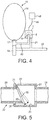
Fig. 4 is a generally schematic view of an extraction system applied to a urinal; -
Fig. 5 is a longitudinal sectional view through a non-return valve; -
Fig. 6 is a generally schematic view of an extraction system applied to a toilet bowl and cistern; -
Fig. 7 is a generally schematic view of a variation of the extraction system ofFig. 6 ; and -
Fig. 8 shows an embodiment of the present invention, including a fan and housing with discharge of air from the air outlet of the extraction system via an absorbent filter unit to atmosphere. - Although none of the arrangements illustrated in
Figs. 1 to 7 is within the scope of the Claims of this Divisional Application, these Figures are useful for a better understanding of the extraction system ofFig. 8 and how it may be incorporated into a lavatory installation. - A shallow housing 1 for a
centrifugal fan 2 is shown inFigs. 1 and2 . The housing comprises afront wall 3 and arear wall 4.Centrifugal fan 2 is preferably a radial blower. Suitable 12 volt DC radial blowers with electronically commutated external rotor motor are available from ebm-papst UK Ltd of Chelmsford, Essex under the trade designation REF 100-11/12, and have a total thickness of fan and motor of under 25mm. The motor offan 2 is mounted by screws tomounts 5 onrear wall 4. Aninlet stub pipe 6 is mounted centrally offront wall 3 via afrustoconical portion 7 to defineplenum 8 for inlet air on the inlet side offan 2. The fan draws air in axially and ejects it in a tangential direction. The fan blades are preferably backwardly curved to reduce noise and increase efficiency.Side walls 9 extending perpendicular to the front wall extend from each edge of front wall 1 towards the rear wall. Aninterior wall 10 is mounted within a chamber effectively defined by the front wall and side walls to guide air flow towards anoutlet stub pipe 11 mounted in one side wall. It will be seen thatinterior wall 10 follows the cylindrical profile of the fan at a fixed radial separation over three-quarters of a circumference before diverging tooutlet 11.Front wall 3 is generally square apart from three of its four corners, which are cut-away. As best shown in the scrap sectional view ofFig. 3 , aperturedtriangular flanges 12 are mounted toside walls 9 at their edges furthest fromfront wall 3 at positions corresponding to the cut-away corners. In practice themain portion 13 of housing 1, comprising the front wall with its sidewalls, the flanges and the interior wall may be moulded, for example from acrylic plastics, in one piece.Rear wall 4 forms a complete square with apertured corners corresponding to the positions of aperturedflanges 12. A shallowupstanding wall 14 is integrally formed onrear wall 4, again by moulding therear wall 4 in one piece, at positions just in board of the positions occupied bysidewalls 9 when themain portion 13 is offered up torear wall 4 already mounting thefan 2 and motor. Fixings inserted through the apertures inflanges 12 andrear wall 4 enable the fan and its housing 1 to be mounted to a generally vertical surface. As can be seen fromFig. 1 , the depth of the housing from the front to the rear wall is substantially less than distances across the front and rear walls from one side to the other. - Providing cut-away corners reduces the space occupied by the housing 1. Thus, the remaining corner may also be cut-away, although this is not shown in
Fig. 2 . - Turning now to
Fig. 4 , a urinal 15 comprises aurinal basin 16 with adrain 17 from which urine, together with water used periodically to flush the urinal basin, passes via aconventional water trap 18 to awaste pipe 19.Urinal basin 16 will generally be mounted to a vertical wall. A housing 1 withfan 2 and motor is conveniently mounted alongsideurinal basin 16 on the same wall. Ducting 20 is provided between a region upstream of the water trap andinlet 6 of housing 1. Theducting 20 here comprises piping tapped into the plumbing for the urinal unit belowdrain 17 immediately above itswater trap 18. Ducting 21 connectsoutlet 11 withwaste pipe 19 downstream ofwater trap 18. - The fan motor suitably runs continuously, avoiding reverse penetration of sewer gas, while substantially reducing the odour of urine without needing to mask it with another strong smell. However, for additional security against sewer gas, a
non-return valve 22 may be incorporated in the system, suitably between theoutlet 11 of housing 1 andwaste pipe 19. As shown inFig. 5 ,valve 22 comprises a generallycubic housing 23 defining avalve chamber 24 therewithin. Twostub pipes housing 23. Onestub pipe 25 is simply joined to onewall 27 ofhousing 23. The other penetrates through awall 28 of thehousing 23 oppositewall 27, its end 29 being cut at an angle. Aflap valve 30 is pivoted at 31 so as to overlie cut end 29 by gravity. Air pressure created byfan 2 is sufficient to openflap valve 30 to allow odour-laden air to pass. When the motor stops, the flap valve will close cut end 29 preventing back flushing of sewer gas. - The system illustrated in
Fig. 4 has the advantage that air extraction is applied to the region in which the odour is generated, so that significantly less power is consumed as compared with an extraction system seeking to reduce odour by ventilating the lavatory room as a whole. A typical motor forfan 2 has a consumption of 7.5 watts/hour. - The extraction system illustrated in
Fig. 4 may be applied equally well to a urinal of the kind comprising a trough in which urine is collected before passing via a drain from the trough and a water trap to a waste pipe. In this case, housing 1 would be mounted to a convenient wall, the ducting connection to theinlet 6 comprising piping tapping into plumbing for the urinal between its drain and its water trap, and the ducting connection from theoutlet 11 comprises piping coupling theoutlet 11 to the said waste pipe downstream of the water trap. - Similar odour-reducing extraction may be applied to the toilet bowl of a water closet, as explained with reference to
Figs. 6 and 7 . - A
water closet 32 is schematically illustrated inFig. 6 and comprises atoilet bowl 33 with anoutlet 34 to a conventional S-bend water trap exiting into asoil pipe 35.Toilet bowl 33 is flushed from awater cistern 36 by a flushing mechanism, indicated schematically at 37, which may be operated mechanically by a user (lever, press-button, etc) in conventional fashion or under automatic control (for example a proximity detector) again in a manner known per se, and is typically lifted to allow water within the cistern to pass through an opening into aconventional down pipe 38 issuing intotoilet bowl 33Cistern 36 has awater feed 39 from an external source controlled by afloat valve 40, here a conventional ball-cock 41, which sets a maximum water level in the cistern. Theflushing mechanism 37 here includes a built-inoverflow 42 into thetoilet bowl 33 via the normal flushing downpipe 38. Thecistern 36 has acistern lid 43 with a seal 44. In the arrangement ofFig. 6 , the housing 1, withfan 2 and motor, is mounted to a generallyvertical surface 45 internally of thecistern 36 above the maximum water level thereof. Theinlet 6 is simply open to the air space above the water level in the cistern. Theoutlet 11 is coupled via piping 46 and anon-return valve 22 tosoil pipe 35 downstream of the S-bend. Operation of the extractor unit creates a partial vacuum within the cistern drawing odour-laden air from the toilet bowl via ducting provided by thedown pipe 38 andoverflow pipe 42 into the airspace above the water line within the cistern and hence toinlet 6, the odour-laden air being exhausted via piping 46 to the soil pipe. - Rather than employing the overflow and normal down pipe, a housing 1 within the
cistern 36 may be coupled by a separate pipe from the toilet bowl adjacent its rim toinlet 6. - In another alternative arrangement shown in
Fig. 7 , housing 1 is mounted alongsidecistern 36,inlet 6 being coupled to the air space above the water level in the cistern via apipe 47 through the wall of the cistern. - Whereas urinal systems will normally operate continuously, toilet bowl systems may be set to operate only intermittently, for example by the motor being switched on for a set period from each operation of the flushing mechanism to exhaust odour-laden air from the bowl.
- In the arrangements of
Figs. 4 and7 , there is no problem in supplying electric power to the fan motor. A suitable 12 volt transformer/adaptor 48 may be mounted at a convenient position and coupled to the mains power supply, wiring 49 providing DC power to the motor. With in-cistern installation of the housing 1, wiring 50 from transformer/adaptor 48 is conveniently fed intocistern 36 via piping 46 andoutlet 11, as shown inFig. 6 . - As an alternative, in any of the above arrangements, to fixing the rear of the housing to a (preferably, generally vertical) surface such as a wall or an interior surface of a water cistern, the housing may simply be fitted to, and supported by, the ducting. In this case, the
apertured flanges 12 may be omitted. - Because the preferred fan motors have such small power requirements in all the illustrated arrangements, several such motors may be coupled to a single transformer/adaptor. The adoption of a shallow housing 1 enables the housing to be mounted in an inconspicuous position against the wall of the lavatory room, or within the cistern itself as in the
Fig. 6 arrangement. - For ease of comparison, parts of the extraction system shown in the embodiment of
Fig. 8 that correspond to parts of the extraction systems illustrated inFigs. 1 ,2 and 3 are identified with like reference numerals. - In
Fig. 8 , a shallow housing 1 for a centrifugal fan (not shown, but identically mounted to the fan ofFigs. 1 to 3 ) comprises afront wall 3 and arear wall 4. An airinlet stub pipe 6 is mounted centrally offront wall 3 via afrustoconical portion 7 to defineplenum 8 for inlet air on the inlet side of the fan. The fan draws air in axially and ejects it in a tangential direction.Side walls 9 extending perpendicular to the front wall extend from each edge of front wall 1 towards the rear wall. Rather than being provided with an outlet stub pipe serving as an air outlet, as in the embodiment ofFigs. 1 to 3 , in the present embodiment, tangentially driven air from the centrifugal fan issues into anabsorbent filter unit absorbent mass 101 contained within afilter housing 102 defined betweenextended portions rear walls grille 105 formed in the extendedtop wall 103.Absorbent mass 101 is a carbon filter. The carbon filter is provided in the form of areplaceable filter cartridge 106, as illustrated, in which thefilter mass 101 is mounted to anend wall 107 fitted with atab 108. When the filter mass is full, a user may simply withdraw the cartridge from thehousing 102 by pulling ontab 108. The cartridge can be regenerated by heating to drive off the trapped odour molecules, and can then be re-used. Aperfume source 109 to scent air d to atmosphere from the absorbent filter unit is provided. Optionally, as shown, there may be a second cartridge behind afurther grille 110, and with asimilar tab 111 for removing and replacing it.Cartridge 109 may contain the perfume. - Mounting the filter and the perfume source within the same housing as the fan provides a particularly compact construction.
- Apart from discharge of filtered air to atmosphere, the extraction system may be mounted to urinals or lavatories in all the ways described and illustrated in
Figs. 4 ,6 and 7 .
Claims (8)
- An extraction system suitable for removing unpleasant lavatory odour from a lavatory room, for example a public lavatory, having at least one lavatory unit comprising a receptacle for receiving human liquid or solid waste and having an outlet for such waste; the extraction system being adapted to remove odour from air within the lavatory room at a position upstream of said waste outlet, and being characterised in comprising: a shallow housing (1) having front (3) and rear (4) walls and side walls (9) interconnecting the front and rear walls, the depth of the housing from the front (3) to the rear (4) wall being substantially less than all distances across the front and rear walls from one side to the other thereof, the housing (1) mounting a centrifugal fan (2) with its axis perpendicular to the rear wall, the fan having an axial air inlet (6) located centrally of the front wall for receiving odour-laden air emanating from said lavatory unit on the upstream side of the said waste outlet, and an air outlet from the fan generally tangential to the fan and coupled to discharge air to atmosphere from the extraction system via an absorbent filter unit (101, 102) into which air from the fan issues, the absorbent filter unit comprising an absorbent mass for absorbing odour consisting of a carbon filter provided as a filter cartridge (106), being removable from the filter unit for replacement, and being capable of regeneration, and a perfume source (109) to scent air discharged to atmosphere from the absorbent filter unit.
- An extraction system according to Claim 1, further characterised in that the perfume source comprises a cartridge removable for replacement when spent.
- An extraction system according to Claim 1 or Claim 2, wherein the waste outlet includes a water trap (18); the extraction system being further characterised by a ducting connection (20; 38, 42) being provided from a region upstream of the water trap to the inlet (6).
- A lavatory installation comprising a lavatory unit and an extraction system according to any preceding Claim, further characterised in that the rear wall (4) of the housing is mounted to a generally vertical surface selected from a building wall associated with the installation and an internal surface of a water cistern (36).
- A lavatory installation according to Claim 4, wherein said lavatory unit comprises a receptacle in the form of a toilet bowl (32) provided with a cistern (36), further characterised in that a ducting connection (38, 42, 45; 38, 42, 45, 47) is provided to the air inlet, the ducting connection comprising a pipe or hose coupled from a region of the toilet bowl (32) adjacent its rim to the inlet.
- A lavatory installation according to Claim 5, wherein the cistern has a flushing mechanism (37) with a built-in overflow (38, 42) into the toilet bowl and a cistern lid (43) with a seal, further characterised in that the inlet (6) is open to the interior (45) of the cistern above its water line, and the ducting connection to the inlet comprises the said built-in overflow (38, 42).
- A lavatory installation according to Claim 4, wherein the lavatory unit comprises a urinal (15) with a urinal bowl (16) having an outlet (17) for urine therefrom, further characterised in that the housing (1) is mounted to a wall alongside the urinal bowl, a ducting connection (20) is provided to the air inlet (6), the ducting connection (20) comprising piping tapping into plumbing for the urinal unit downstream of the outlet (17) for urine from the urinal bowl, and immediately above its water trap (18), where the urinal is fitted with a water trap, airflow of odour-laden air to the inlet (6) being via that outlet from the urinal, the said plumbing and the ducting connection to the air inlet.
- A lavatory installation according to Claim 4, wherein the lavatory unit comprises a urinal of the kind comprising a trough in which urine is collected before passing via an outlet comprising a drain from the trough and a water trap to a waste pipe, wherein the housing is mounted to a wall, and wherein a ducting connection is provided to the air inlet, the ducting connection comprising piping tapping into plumbing for the urinal between the drain and the water trap.
Applications Claiming Priority (4)
| Application Number | Priority Date | Filing Date | Title |
|---|---|---|---|
| GB0811607A GB0811607D0 (en) | 2008-06-25 | 2008-06-25 | Lavatory systems |
| GB0908231A GB0908231D0 (en) | 2009-05-14 | 2009-05-14 | Lavatory systems |
| EP09769573A EP2304113A1 (en) | 2008-06-25 | 2009-06-24 | Lavatory systems |
| PCT/GB2009/001594 WO2009156732A1 (en) | 2008-06-25 | 2009-06-24 | Lavatory systems |
Related Parent Applications (1)
| Application Number | Title | Priority Date | Filing Date |
|---|---|---|---|
| EP09769573A Division EP2304113A1 (en) | 2008-06-25 | 2009-06-24 | Lavatory systems |
Publications (2)
| Publication Number | Publication Date |
|---|---|
| EP3037594A1 EP3037594A1 (en) | 2016-06-29 |
| EP3037594B1 true EP3037594B1 (en) | 2020-12-23 |
Family
ID=40972672
Family Applications (2)
| Application Number | Title | Priority Date | Filing Date |
|---|---|---|---|
| EP09769573A Withdrawn EP2304113A1 (en) | 2008-06-25 | 2009-06-24 | Lavatory systems |
| EP16020001.0A Active EP3037594B1 (en) | 2008-06-25 | 2009-06-24 | Lavatory systems |
Family Applications Before (1)
| Application Number | Title | Priority Date | Filing Date |
|---|---|---|---|
| EP09769573A Withdrawn EP2304113A1 (en) | 2008-06-25 | 2009-06-24 | Lavatory systems |
Country Status (6)
| Country | Link |
|---|---|
| US (1) | US9957703B2 (en) |
| EP (2) | EP2304113A1 (en) |
| AU (1) | AU2009263971B2 (en) |
| CA (1) | CA2764457C (en) |
| GB (1) | GB2462166B (en) |
| WO (1) | WO2009156732A1 (en) |
Families Citing this family (5)
| Publication number | Priority date | Publication date | Assignee | Title |
|---|---|---|---|---|
| ZA201005706B (en) * | 2009-08-30 | 2012-05-30 | Hugh Ross-Kent Dylan | Removal of odours from a toilet bowl |
| FR2986581B1 (en) * | 2012-02-03 | 2015-09-04 | Aldes Aeraulique | CONTROLLED MECHANICAL VENTILATION DEVICE AND MANUFACTURING METHOD THEREOF |
| US11473286B2 (en) | 2017-03-02 | 2022-10-18 | Hound Tech Llc | Filtration assembly for reducing malaodors in air and aerosolized waste from toilets |
| US12241244B2 (en) | 2022-02-07 | 2025-03-04 | Hound Tech Llc | Portable air filtration assembly for toilets |
| US12582272B2 (en) * | 2022-08-22 | 2026-03-24 | Robert Matters | Bodily waste harvesting, pathogen destroying, waterless toilet |
Family Cites Families (17)
| Publication number | Priority date | Publication date | Assignee | Title |
|---|---|---|---|---|
| US3763505A (en) * | 1972-02-17 | 1973-10-09 | J Zimmerman | Toilet ventilation device |
| US4166298A (en) * | 1976-02-20 | 1979-09-04 | Pearson Raymond H | Deodorizer for toilets |
| GB2178456A (en) | 1985-08-02 | 1987-02-11 | Chang Tsui Ying | Odour extractor apparatus for use with lavatories |
| FR2593535A1 (en) | 1985-12-18 | 1987-07-31 | Hubert Juan | Odour extractor, particularly for a lavatory bowl |
| US5361422A (en) * | 1993-05-21 | 1994-11-08 | Ray T. Vincent | Toilet ventilating system |
| US5394569A (en) * | 1994-03-21 | 1995-03-07 | Poirier; Paul | Air venting apparatus for WC |
| US5454122A (en) * | 1994-04-22 | 1995-10-03 | Bergeron; Donald J. | Toilet ventilator with room air freshener and comfort heater |
| US5727263A (en) * | 1995-02-10 | 1998-03-17 | Hugo Ceja Estrada; Juan Jose | Toilet ventilation system |
| DE19651076A1 (en) * | 1996-12-09 | 1998-06-10 | Matthias Roskopf | WC with bowl cistern and run-off line |
| US6279173B1 (en) * | 1999-04-12 | 2001-08-28 | D2M, Inc. | Devices and methods for toilet ventilation using a radar sensor |
| DE50213420D1 (en) * | 2001-04-06 | 2009-05-20 | Geberit Technik Ag | Odor trap for a waterless urinal |
| US6643850B2 (en) * | 2002-03-21 | 2003-11-11 | Hp Intellectual Corp. | Odor removal system |
| US6760928B1 (en) * | 2002-12-03 | 2004-07-13 | Cirilo Rodriguez | System and method for controlling toilet odors |
| US7473074B2 (en) * | 2006-02-13 | 2009-01-06 | Intelligent Home Products, Inc. | Exhaust fan |
| DE102006010461B3 (en) | 2006-03-03 | 2007-10-25 | Woco Industrietechnik Gmbh | Plastic compressor housing |
| US7797766B2 (en) * | 2006-05-08 | 2010-09-21 | Ellinger Robert W | Toilet odor exhaust device |
| US20080127403A1 (en) * | 2006-11-30 | 2008-06-05 | Airex, Inc. | Ventilating fan with grill having high static pressure resistance |
-
2009
- 2009-06-24 AU AU2009263971A patent/AU2009263971B2/en active Active
- 2009-06-24 CA CA2764457A patent/CA2764457C/en active Active
- 2009-06-24 EP EP09769573A patent/EP2304113A1/en not_active Withdrawn
- 2009-06-24 GB GB0910860A patent/GB2462166B/en active Active
- 2009-06-24 WO PCT/GB2009/001594 patent/WO2009156732A1/en not_active Ceased
- 2009-06-24 US US13/000,048 patent/US9957703B2/en active Active
- 2009-06-24 EP EP16020001.0A patent/EP3037594B1/en active Active
Non-Patent Citations (1)
| Title |
|---|
| None * |
Also Published As
| Publication number | Publication date |
|---|---|
| US20110138525A1 (en) | 2011-06-16 |
| EP2304113A1 (en) | 2011-04-06 |
| GB2462166A (en) | 2010-02-03 |
| WO2009156732A1 (en) | 2009-12-30 |
| GB0910860D0 (en) | 2009-08-05 |
| EP3037594A1 (en) | 2016-06-29 |
| CA2764457A1 (en) | 2009-12-30 |
| AU2009263971A1 (en) | 2009-12-30 |
| CA2764457C (en) | 2016-08-23 |
| US9957703B2 (en) | 2018-05-01 |
| GB2462166B (en) | 2011-12-07 |
| AU2009263971B2 (en) | 2015-07-16 |
Similar Documents
| Publication | Publication Date | Title |
|---|---|---|
| US6983491B2 (en) | Odor removal apparatus and/or methods | |
| US20090056007A1 (en) | Ventilation system for a toilet | |
| CA2764457C (en) | Lavatory systems | |
| US20160122986A1 (en) | System for supplying additive fluids within a waste disposal water supply system | |
| US7103925B2 (en) | Odor eliminating system for a toilet, toilet including the odor eliminating system, and toilet seat assembly | |
| US20160122981A1 (en) | Secondary water supply system for a waste disposal | |
| US20050050621A1 (en) | Toilet ventilation system and method | |
| JP2010285863A (en) | Ventilated toilet | |
| US5044018A (en) | Toilet with device for removing unpleasant odors | |
| US20100058525A1 (en) | Toilets | |
| US20140338111A1 (en) | Odor Eliminating System for a Toilet | |
| GB2372263A (en) | Odour extraction system for a toilet bowl or urinal | |
| EP1492928B1 (en) | Stench-free toilet system | |
| US20080256693A1 (en) | Systems and Apparatus for Toilet Odour Removal | |
| CA3272545C (en) | Suction and odour evacuation system with passive and continuous hydraulic sealing | |
| US20160122985A1 (en) | Air gap switch for a waste disposal water supply system | |
| CA2175938A1 (en) | Toilet bowl odour extractor | |
| CA3272545A1 (en) | Suction and odour evacuation system with passive and continuous hydraulic sealing | |
| WO2002061214A1 (en) | An odour extraction system for a urinal | |
| WO2021071442A1 (en) | Odor vacuum toilet | |
| WO2005035886A1 (en) | Ventilation system, kit and method for odor removal from sanitary plumbing fixtures | |
| WO2021086272A1 (en) | Odor vacuum toilet | |
| CN1187859A (en) | Portable Toilet Vent | |
| HK1074470B (en) | Stench-free toilet system | |
| AU2307201A (en) | An odour extraction system for a toilet, urinal, bidet, and the like |
Legal Events
| Date | Code | Title | Description |
|---|---|---|---|
| PUAI | Public reference made under article 153(3) epc to a published international application that has entered the european phase |
Free format text: ORIGINAL CODE: 0009012 |
|
| AC | Divisional application: reference to earlier application |
Ref document number: 2304113 Country of ref document: EP Kind code of ref document: P |
|
| AK | Designated contracting states |
Kind code of ref document: A1 Designated state(s): AT BE BG CH CY CZ DE DK EE ES FI FR GB GR HR HU IE IS IT LI LT LU LV MC MK MT NL NO PL PT RO SE SI SK TR |
|
| STAA | Information on the status of an ep patent application or granted ep patent |
Free format text: STATUS: REQUEST FOR EXAMINATION WAS MADE |
|
| 17P | Request for examination filed |
Effective date: 20161223 |
|
| RBV | Designated contracting states (corrected) |
Designated state(s): AT BE BG CH CY CZ DE DK EE ES FI FR GB GR HR HU IE IS IT LI LT LU LV MC MK MT NL NO PL PT RO SE SI SK TR |
|
| STAA | Information on the status of an ep patent application or granted ep patent |
Free format text: STATUS: EXAMINATION IS IN PROGRESS |
|
| 17Q | First examination report despatched |
Effective date: 20170719 |
|
| RAP1 | Party data changed (applicant data changed or rights of an application transferred) |
Owner name: WASHROOM-WIZARD LTD |
|
| GRAP | Despatch of communication of intention to grant a patent |
Free format text: ORIGINAL CODE: EPIDOSNIGR1 |
|
| STAA | Information on the status of an ep patent application or granted ep patent |
Free format text: STATUS: GRANT OF PATENT IS INTENDED |
|
| INTG | Intention to grant announced |
Effective date: 20200714 |
|
| GRAS | Grant fee paid |
Free format text: ORIGINAL CODE: EPIDOSNIGR3 |
|
| GRAA | (expected) grant |
Free format text: ORIGINAL CODE: 0009210 |
|
| STAA | Information on the status of an ep patent application or granted ep patent |
Free format text: STATUS: THE PATENT HAS BEEN GRANTED |
|
| AC | Divisional application: reference to earlier application |
Ref document number: 2304113 Country of ref document: EP Kind code of ref document: P |
|
| AK | Designated contracting states |
Kind code of ref document: B1 Designated state(s): AT BE BG CH CY CZ DE DK EE ES FI FR GR HR HU IE IS IT LI LT LU LV MC MK MT NL NO PL PT RO SE SI SK TR |
|
| RBV | Designated contracting states (corrected) |
Designated state(s): AT BE BG CH CY CZ DE DK EE ES FI FR GR HR HU IE IS IT LI LT LU LV MC MK MT NL NO PL PT RO SE SI SK TR |
|
| REG | Reference to a national code |
Ref country code: DE Ref legal event code: R096 Ref document number: 602009063218 Country of ref document: DE |
|
| REG | Reference to a national code |
Ref country code: AT Ref legal event code: REF Ref document number: 1347862 Country of ref document: AT Kind code of ref document: T Effective date: 20210115 |
|
| REG | Reference to a national code |
Ref country code: IE Ref legal event code: FG4D |
|
| PG25 | Lapsed in a contracting state [announced via postgrant information from national office to epo] |
Ref country code: NO Free format text: LAPSE BECAUSE OF FAILURE TO SUBMIT A TRANSLATION OF THE DESCRIPTION OR TO PAY THE FEE WITHIN THE PRESCRIBED TIME-LIMIT Effective date: 20210323 Ref country code: FI Free format text: LAPSE BECAUSE OF FAILURE TO SUBMIT A TRANSLATION OF THE DESCRIPTION OR TO PAY THE FEE WITHIN THE PRESCRIBED TIME-LIMIT Effective date: 20201223 Ref country code: GR Free format text: LAPSE BECAUSE OF FAILURE TO SUBMIT A TRANSLATION OF THE DESCRIPTION OR TO PAY THE FEE WITHIN THE PRESCRIBED TIME-LIMIT Effective date: 20210324 |
|
| REG | Reference to a national code |
Ref country code: AT Ref legal event code: MK05 Ref document number: 1347862 Country of ref document: AT Kind code of ref document: T Effective date: 20201223 |
|
| REG | Reference to a national code |
Ref country code: NL Ref legal event code: MP Effective date: 20201223 |
|
| PG25 | Lapsed in a contracting state [announced via postgrant information from national office to epo] |
Ref country code: BG Free format text: LAPSE BECAUSE OF FAILURE TO SUBMIT A TRANSLATION OF THE DESCRIPTION OR TO PAY THE FEE WITHIN THE PRESCRIBED TIME-LIMIT Effective date: 20210323 Ref country code: LV Free format text: LAPSE BECAUSE OF FAILURE TO SUBMIT A TRANSLATION OF THE DESCRIPTION OR TO PAY THE FEE WITHIN THE PRESCRIBED TIME-LIMIT Effective date: 20201223 Ref country code: SE Free format text: LAPSE BECAUSE OF FAILURE TO SUBMIT A TRANSLATION OF THE DESCRIPTION OR TO PAY THE FEE WITHIN THE PRESCRIBED TIME-LIMIT Effective date: 20201223 |
|
| PG25 | Lapsed in a contracting state [announced via postgrant information from national office to epo] |
Ref country code: NL Free format text: LAPSE BECAUSE OF FAILURE TO SUBMIT A TRANSLATION OF THE DESCRIPTION OR TO PAY THE FEE WITHIN THE PRESCRIBED TIME-LIMIT Effective date: 20201223 Ref country code: HR Free format text: LAPSE BECAUSE OF FAILURE TO SUBMIT A TRANSLATION OF THE DESCRIPTION OR TO PAY THE FEE WITHIN THE PRESCRIBED TIME-LIMIT Effective date: 20201223 |
|
| REG | Reference to a national code |
Ref country code: LT Ref legal event code: MG9D |
|
| PG25 | Lapsed in a contracting state [announced via postgrant information from national office to epo] |
Ref country code: SK Free format text: LAPSE BECAUSE OF FAILURE TO SUBMIT A TRANSLATION OF THE DESCRIPTION OR TO PAY THE FEE WITHIN THE PRESCRIBED TIME-LIMIT Effective date: 20201223 Ref country code: RO Free format text: LAPSE BECAUSE OF FAILURE TO SUBMIT A TRANSLATION OF THE DESCRIPTION OR TO PAY THE FEE WITHIN THE PRESCRIBED TIME-LIMIT Effective date: 20201223 Ref country code: PT Free format text: LAPSE BECAUSE OF FAILURE TO SUBMIT A TRANSLATION OF THE DESCRIPTION OR TO PAY THE FEE WITHIN THE PRESCRIBED TIME-LIMIT Effective date: 20210423 Ref country code: CZ Free format text: LAPSE BECAUSE OF FAILURE TO SUBMIT A TRANSLATION OF THE DESCRIPTION OR TO PAY THE FEE WITHIN THE PRESCRIBED TIME-LIMIT Effective date: 20201223 Ref country code: EE Free format text: LAPSE BECAUSE OF FAILURE TO SUBMIT A TRANSLATION OF THE DESCRIPTION OR TO PAY THE FEE WITHIN THE PRESCRIBED TIME-LIMIT Effective date: 20201223 Ref country code: LT Free format text: LAPSE BECAUSE OF FAILURE TO SUBMIT A TRANSLATION OF THE DESCRIPTION OR TO PAY THE FEE WITHIN THE PRESCRIBED TIME-LIMIT Effective date: 20201223 |
|
| PG25 | Lapsed in a contracting state [announced via postgrant information from national office to epo] |
Ref country code: AT Free format text: LAPSE BECAUSE OF FAILURE TO SUBMIT A TRANSLATION OF THE DESCRIPTION OR TO PAY THE FEE WITHIN THE PRESCRIBED TIME-LIMIT Effective date: 20201223 Ref country code: PL Free format text: LAPSE BECAUSE OF FAILURE TO SUBMIT A TRANSLATION OF THE DESCRIPTION OR TO PAY THE FEE WITHIN THE PRESCRIBED TIME-LIMIT Effective date: 20201223 |
|
| REG | Reference to a national code |
Ref country code: DE Ref legal event code: R097 Ref document number: 602009063218 Country of ref document: DE |
|
| PG25 | Lapsed in a contracting state [announced via postgrant information from national office to epo] |
Ref country code: IS Free format text: LAPSE BECAUSE OF FAILURE TO SUBMIT A TRANSLATION OF THE DESCRIPTION OR TO PAY THE FEE WITHIN THE PRESCRIBED TIME-LIMIT Effective date: 20210423 |
|
| PG25 | Lapsed in a contracting state [announced via postgrant information from national office to epo] |
Ref country code: IT Free format text: LAPSE BECAUSE OF FAILURE TO SUBMIT A TRANSLATION OF THE DESCRIPTION OR TO PAY THE FEE WITHIN THE PRESCRIBED TIME-LIMIT Effective date: 20201223 |
|
| PLBE | No opposition filed within time limit |
Free format text: ORIGINAL CODE: 0009261 |
|
| STAA | Information on the status of an ep patent application or granted ep patent |
Free format text: STATUS: NO OPPOSITION FILED WITHIN TIME LIMIT |
|
| PG25 | Lapsed in a contracting state [announced via postgrant information from national office to epo] |
Ref country code: DK Free format text: LAPSE BECAUSE OF FAILURE TO SUBMIT A TRANSLATION OF THE DESCRIPTION OR TO PAY THE FEE WITHIN THE PRESCRIBED TIME-LIMIT Effective date: 20201223 Ref country code: ES Free format text: LAPSE BECAUSE OF FAILURE TO SUBMIT A TRANSLATION OF THE DESCRIPTION OR TO PAY THE FEE WITHIN THE PRESCRIBED TIME-LIMIT Effective date: 20201223 |
|
| 26N | No opposition filed |
Effective date: 20210924 |
|
| PG25 | Lapsed in a contracting state [announced via postgrant information from national office to epo] |
Ref country code: MC Free format text: LAPSE BECAUSE OF FAILURE TO SUBMIT A TRANSLATION OF THE DESCRIPTION OR TO PAY THE FEE WITHIN THE PRESCRIBED TIME-LIMIT Effective date: 20201223 |
|
| PG25 | Lapsed in a contracting state [announced via postgrant information from national office to epo] |
Ref country code: SI Free format text: LAPSE BECAUSE OF FAILURE TO SUBMIT A TRANSLATION OF THE DESCRIPTION OR TO PAY THE FEE WITHIN THE PRESCRIBED TIME-LIMIT Effective date: 20201223 |
|
| PG25 | Lapsed in a contracting state [announced via postgrant information from national office to epo] |
Ref country code: LU Free format text: LAPSE BECAUSE OF NON-PAYMENT OF DUE FEES Effective date: 20210624 |
|
| PG25 | Lapsed in a contracting state [announced via postgrant information from national office to epo] |
Ref country code: IE Free format text: LAPSE BECAUSE OF NON-PAYMENT OF DUE FEES Effective date: 20210624 |
|
| PG25 | Lapsed in a contracting state [announced via postgrant information from national office to epo] |
Ref country code: IS Free format text: LAPSE BECAUSE OF FAILURE TO SUBMIT A TRANSLATION OF THE DESCRIPTION OR TO PAY THE FEE WITHIN THE PRESCRIBED TIME-LIMIT Effective date: 20210423 |
|
| PG25 | Lapsed in a contracting state [announced via postgrant information from national office to epo] |
Ref country code: HU Free format text: LAPSE BECAUSE OF FAILURE TO SUBMIT A TRANSLATION OF THE DESCRIPTION OR TO PAY THE FEE WITHIN THE PRESCRIBED TIME-LIMIT; INVALID AB INITIO Effective date: 20090624 Ref country code: CY Free format text: LAPSE BECAUSE OF FAILURE TO SUBMIT A TRANSLATION OF THE DESCRIPTION OR TO PAY THE FEE WITHIN THE PRESCRIBED TIME-LIMIT Effective date: 20201223 |
|
| PG25 | Lapsed in a contracting state [announced via postgrant information from national office to epo] |
Ref country code: MK Free format text: LAPSE BECAUSE OF FAILURE TO SUBMIT A TRANSLATION OF THE DESCRIPTION OR TO PAY THE FEE WITHIN THE PRESCRIBED TIME-LIMIT Effective date: 20201223 |
|
| PG25 | Lapsed in a contracting state [announced via postgrant information from national office to epo] |
Ref country code: MT Free format text: LAPSE BECAUSE OF FAILURE TO SUBMIT A TRANSLATION OF THE DESCRIPTION OR TO PAY THE FEE WITHIN THE PRESCRIBED TIME-LIMIT Effective date: 20201223 |
|
| PGFP | Annual fee paid to national office [announced via postgrant information from national office to epo] |
Ref country code: DE Payment date: 20250604 Year of fee payment: 17 |
|
| PGFP | Annual fee paid to national office [announced via postgrant information from national office to epo] |
Ref country code: BE Payment date: 20250623 Year of fee payment: 17 |
|
| PGFP | Annual fee paid to national office [announced via postgrant information from national office to epo] |
Ref country code: FR Payment date: 20250627 Year of fee payment: 17 |
|
| PGFP | Annual fee paid to national office [announced via postgrant information from national office to epo] |
Ref country code: CH Payment date: 20250701 Year of fee payment: 17 |
|
| PG25 | Lapsed in a contracting state [announced via postgrant information from national office to epo] |
Ref country code: TR Free format text: LAPSE BECAUSE OF FAILURE TO SUBMIT A TRANSLATION OF THE DESCRIPTION OR TO PAY THE FEE WITHIN THE PRESCRIBED TIME-LIMIT Effective date: 20201223 |