EP3037336A1 - Sprocket assembly for a bicycle - Google Patents
Sprocket assembly for a bicycle Download PDFInfo
- Publication number
- EP3037336A1 EP3037336A1 EP15196198.4A EP15196198A EP3037336A1 EP 3037336 A1 EP3037336 A1 EP 3037336A1 EP 15196198 A EP15196198 A EP 15196198A EP 3037336 A1 EP3037336 A1 EP 3037336A1
- Authority
- EP
- European Patent Office
- Prior art keywords
- sprocket
- last
- diameter
- spacer
- sprockets
- Prior art date
- Legal status (The legal status is an assumption and is not a legal conclusion. Google has not performed a legal analysis and makes no representation as to the accuracy of the status listed.)
- Granted
Links
Images




Classifications
-
- B—PERFORMING OPERATIONS; TRANSPORTING
- B62—LAND VEHICLES FOR TRAVELLING OTHERWISE THAN ON RAILS
- B62M—RIDER PROPULSION OF WHEELED VEHICLES OR SLEDGES; POWERED PROPULSION OF SLEDGES OR SINGLE-TRACK CYCLES; TRANSMISSIONS SPECIALLY ADAPTED FOR SUCH VEHICLES
- B62M9/00—Transmissions characterised by use of an endless chain, belt, or the like
- B62M9/04—Transmissions characterised by use of an endless chain, belt, or the like of changeable ratio
- B62M9/06—Transmissions characterised by use of an endless chain, belt, or the like of changeable ratio using a single chain, belt, or the like
- B62M9/10—Transmissions characterised by use of an endless chain, belt, or the like of changeable ratio using a single chain, belt, or the like involving different-sized wheels, e.g. rear sprocket chain wheels selectively engaged by the chain, belt, or the like
- B62M9/12—Transmissions characterised by use of an endless chain, belt, or the like of changeable ratio using a single chain, belt, or the like involving different-sized wheels, e.g. rear sprocket chain wheels selectively engaged by the chain, belt, or the like the chain, belt, or the like being laterally shiftable, e.g. using a rear derailleur
-
- B—PERFORMING OPERATIONS; TRANSPORTING
- B62—LAND VEHICLES FOR TRAVELLING OTHERWISE THAN ON RAILS
- B62M—RIDER PROPULSION OF WHEELED VEHICLES OR SLEDGES; POWERED PROPULSION OF SLEDGES OR SINGLE-TRACK CYCLES; TRANSMISSIONS SPECIALLY ADAPTED FOR SUCH VEHICLES
- B62M9/00—Transmissions characterised by use of an endless chain, belt, or the like
- B62M9/04—Transmissions characterised by use of an endless chain, belt, or the like of changeable ratio
- B62M9/06—Transmissions characterised by use of an endless chain, belt, or the like of changeable ratio using a single chain, belt, or the like
- B62M9/10—Transmissions characterised by use of an endless chain, belt, or the like of changeable ratio using a single chain, belt, or the like involving different-sized wheels, e.g. rear sprocket chain wheels selectively engaged by the chain, belt, or the like
Definitions
- the present invention relates to a sprocket assembly for a bicycle, in particular for a racing bicycle.
- the bicycle is a mechanical device moved by muscle power, hence one of the main requirements to be satisfied in the field of bicycles, particularly racing bicycles, is to allow the best possible exploitation of such a muscle power.
- a conventional motion transmission system comprises, in the rear part of the bicycle, a hub associated with the rear wheel of the bicycle and provided with a body, in the jargon known as “freewheel body”, capable of rotating idly with respect to the hub in one direction of rotation and of pushing the hub into rotation in the opposite direction.
- the freewheel body is in general a cylindrical body having, on the radially outer surface thereof, a plurality of longitudinal grooves configured to engage the sprockets of decreasing diameter of a sprocket assembly.
- the sprockets in turn are engaged with, and pushed in rotation by, a chain which receives the movement from at least one toothed front sprocket associated with one of the two crank arms coupled with the shaft of the bottom bracket assembly of the bicycle.
- the sprockets are generally made of an extremely strong material (like steel or titanium) to withstand the wearing generated by the sliding of the chain and the loads which they are subjected to during operation.
- the sprockets can comprise a radially inner surface provided with grooves configured to engage the grooves of the freewheel body.
- the sprockets can be supported by support elements, often made from light material (like aluminium), having a radially inner surface provided with grooves configured to engage the grooves of the freewheel body.
- a support element can also support more than one sprocket.
- each spacer is arranged between two adjacent sprockets or between two adjacent support elements, if provided.
- the support elements support two sprockets arranged on opposite sides, they also act as spacers.
- the spacers can comprise a radially inner surface provided with groves configured to engage the grooves of the freewheel body.
- sprocket assemblies In the field of racing bicycles, sprocket assemblies are known having nine, ten or even eleven sprockets.
- the sprocket having the smallest diameter of the sprocket assembly has a radially outer toothing (configured to engage the chain) with, typically, eleven or twelve teeth.
- the Applicant has felt the need to add, to a sprocket assembly of the type described above, an additional sprocket having a smaller number of teeth with respect to the number of teeth of the sprocket having the smallest diameter of the sprocket assembly, so as to provide the cyclist with a further gear ratio characterised by being extremely long, thus very suitable for flat terrain, downhill and also for sprint finishes in cycling competitions.
- the aforementioned additional sprocket is also indicated as “last sprocket”, whereas the aforementioned sprocket having a smaller diameter is also indicated as “second-last sprocket”.
- an additional sprocket in a sprocket assembly requires the provision of an additional spacer arranged between such a sprocket and the sprocket having a larger diameter which is immediately adjacent thereto, such a spacer being configured to be fitted onto a free end portion of the freewheel body.
- the additional spacer in order to ensure that the additional spacer has a sufficient structural strength, since the inner diameter of the additional spacer is imposed by the outer radial size of the freewheel body, the additional spacer should have an outer diameter that in certain cases can be greater than the diameter defined in the additional sprocket at the bottom of the throats of the toothing.
- the present invention therefore, in a first aspect thereof, relates to a bicycle sprocket assembly according to claim 1.
- the present invention relates to a bicycle sprocket assembly comprising:
- the provision of the aforementioned recessed areas on the radially outer surface of the additional spacer (last spacer) allows the correct meshing of the chain on the teeth of the additional sprocket (last sprocket) in the case in which the outer radial size of the additional spacer (last spacer) is greater than that of the bottom surfaces of the throats of the teeth of the additional sprocket (last sprocket).
- the sprocket assembly of the present invention can comprise one or more of the following preferred features, taken individually or in combination.
- the last sprocket (additional sprocket) has ten teeth and the second-last sprocket has eleven or twelve teeth.
- the last sprocket (additional sprocket) is configured to be mounted canti-levered with respect to said freewheel body.
- the canti-levered mounting of the last sprocket (additional sprocket) with respect to the freewheel body makes it possible to use the sprocket assembly provided with the aforementioned last sprocket (additional sprocket) with freewheel bodies having conventional shape and size, without the need to carry out any mechanical processing on such freewheel bodies.
- the freewheel body has a radially outer surface comprising a plurality of longitudinal grooves defining a plurality of projections and a plurality of recesses, each recess being arranged between two consecutive projections, wherein said projections comprise respective head surfaces that belong to a third circumference having a fourth diameter greater than said first diameter.
- the last spacer (additional spacer) is made in a single piece with the last sprocket (additional sprocket) and the second-last sprocket.
- the last sprocket (additional sprocket), the last spacer (additional spacer) and the second-last sprocket are made in a single piece with a third-last sprocket of said plurality of sprockets.
- the last sprocket (additional sprocket), the last spacer (additional spacer) and the second-last sprocket can be made in distinct pieces and can be coupled together so as to form a preassembled module configured to later be coupled with the freewheel body.
- the sprocket assembly of the invention comprises a second-last spacer arranged between the second-last sprocket and the third-last sprocket, said second-last spacer comprising a radially outer surface having a fifth diameter greater than said second diameter.
- the radially inner surface of the last spacer is a cylindrical surface with a circular section.
- the second-last sprocket comprises a radially inner surface having a shape matching the radially outer surface of said freewheel body.
- a radially inner surface comprises longitudinal grooves configured to engage the grooves provided on the radially outer surface of the freewheel body.
- a bicycle sprocket assembly in accordance with the present invention is shown.
- the sprocket assembly is wholly indicated with 10.
- the sprocket assembly 10 is mounted on a freewheel body 20 of a hub for a rear bicycle wheel.
- the hub comprises a hub body 15 and a freewheel body 20.
- the freewheel body 20 is coupled with the hub body 15 through any known system (not shown) through which the freewheel body 20 can rotate idly in one direction of rotation about a rotation axis X-X and push the hub body 15 in the opposite direction of rotation.
- Figures 3a, 3b and figures 6a, 6b respectively show two different types of freewheel bodies 20 of the conventional type available on the market, which differ in that they have different shapes and sizes.
- the freewheel body 20 has a substantially cylindrical shape and has, on the radially outer surface 21 thereof, a plurality of longitudinal grooves 22 configured to be coupled with the sprocket assembly 10 to allow the rotation as a single unit of the sprocket assembly 10 and of the freewheel body 20 about the rotation axis X-X.
- the longitudinal grooves 22 define, on the radially outer surface 21 of the freewheel body 20, projections 24 and recesses 26.
- the projections 24 comprise respective head surfaces 24a that belong to an ideal circumference having its centre on the rotation axis X-X and a diameter D4 for example equal to about 35 mm in the type of freewheel body 20 shown in figures 3a and 3b and equal to about 34.4 mm in the type of freewheel body 20 shown in figures 6a and 6b .
- the recesses 26 comprise respective base surfaces 26a that belong to an ideal circumference having its centre on the rotation axis X-X and a diameter D6 for example equal to about 29 mm in the type of freewheel body 20 shown in figures 3a and 3b and equal to about 32.1 mm in the type of freewheel body 20 shown in figures 6a and 6b .
- the sprocket assembly 10 comprises a plurality of sprockets 12 having decreasing diameter (reference numeral 12 is associated with just some of the sprockets shown).
- Reference numeral 12a indicates the sprocket having the largest diameter and reference numerals 12b, 12c, 12d indicate the three sprockets having smaller diameter of the sprocket assembly 10, wherein sprocket 12c has a smaller diameter than that of sprocket 12b and greater than that of sprocket 12d.
- Sprocket 12d is the one which in the introductory part of this description and in the subsequent claims is also indicated as “additional sprocket” or “last sprocket”, whereas sprocket 12c is the one which in the introductory part of this description and in the subsequent claims is also indicated as “second-last sprocket” and sprocket 12b is the one which in the introductory part of this description and in the subsequent claims is also indicated as "third-last sprocket”.
- the sprocket assembly 10 comprises eleven sprockets in total.
- Sprocket 12a is mounted on the freewheel body 20 and abuts against an axial abutment element 28 of the freewheel body 20.
- Sprocket 12d is mounted canti-levered with respect to the freewheel body 20, as shown in figures 4a , 4b and 7a , 7b .
- the sprocket assembly 10 further comprises a plurality of spacers 14, each arranged between two consecutive sprockets 12 (reference numeral 14 is associated with just some of the spacers shown).
- Reference numeral 14a indicates the spacer arranged between sprockets 12b and 12c, whereas reference numeral 14b indicates the spacer arranged between sprockets 12b and 12c.
- Spacer 14a is the one which in the introductory part of this description and in the subsequent claims is also indicated as “second-last spacer”
- spacer 14b is the one which in the introductory part of this description and in the subsequent claims is also indicated as “last spacer”.
- Spacer 14a is mounted on the freewheel body 20 at the projections 24, whereas spacer 14b is mounted on the freewheel body 20 at a free end portion 23 thereof whose radially outer surface has no grooves 22.
- the attached figures show a conventional chain 40 engaged on the sprocket 12d.
- the chain 40 comprises a succession of links 42, each link consisting of a pair of plates 44 facing one another and spaced apart to define an insertion space for a tooth of the sprocket 12d.
- the plates 44 of a link 42 are coupled with the plates 44 of the subsequent link 42 through a rivet 46, which in turn is surrounded by a bush 48 capable of rotating freely with respect to the rivet 46.
- FIG. 2 shows a part of the sprocket assembly 10.
- a sprocket module is shown comprising the three sprockets of smallest diameter 12b, 12c and 12d of the sprocket assembly 10 and the spacers 14a and 14b.
- Such a module is wholly indicated with 30.
- the module 30 comprises a sprocket 12d having ten teeth, a sprocket 12c having eleven teeth and a sprocket 12b having twelve teeth.
- FIGS 4a , 4b and figures 7a , 7b respectively illustrate two different embodiments of the module 30, which differ in that they have different shapes and sizes.
- Sprockets 12b, 12c and 12d and spacers 14a and 14b are made in a single piece.
- sprockets 12b, 12c and 12d and spacers 14a and 14b are made in a single piece.
- sprockets 12b, 12c and 12d and spacers 14a and 14b are made in distinct pieces and are coupled together so as to form a preassembled module.
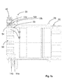
- Figure 4a shows a first embodiment of the sprocket module 30 of figure 2 mounted on the freewheel body 20 of figures 3a, 3b
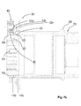
- figure 7a shows a second embodiment of the sprocket module 30 of figure 2 mounted on the freewheel body 20 of figures 6a, 6b .
- the sprocket module 30 of figure 7a differs from the sprocket module 30 of figure 4a in that it has, being equal the outer radial dimensions of sprockets 12b, 12c, 12d and spacers 14a, 14b and being equal the number of teeth of each of the sprockets 12b, 12c, 12d, larger inner radial dimensions.
- a locking ring nut 50 is screwed onto the freewheel body 20.
- the locking ring nut 50 comprises a substantially cylindrical portion 52 and a substantially annular portion 54 that projects radially outwards with respect to the substantially cylindrical portion 52.
- the substantially cylindrical portion 52 is provided with an outer threading 53 that is screwed onto an inner threading 25 of the freewheel body 20.
- the substantially annular portion 54 abuts axially on the sprocket 12d, locking the sprocket assembly 10 on the freewheel body 20.
- Figures 4b and 7b show a variant of the sprocket module 30 and of the locking ring nut 50 respectively of figures 4a and 7a .
- the sprocket module 30 of figures 4b , 7b differs from that of figures 4a , 7a solely in that a bevel or flaring 32 is provided on a radially inner surface of the sprocket 12d.
- the locking ring nut 50 of figures 4b , 7b differs from that of figures 4a , 7a solely in that a radiused surface 56 is provided between the substantially cylindrical portion 52 and the substantially annular portion 54.
- the sprocket 12d has a plurality of throats 121 d, each arranged between two consecutive teeth 122d.
- the throats 121 d comprise respective bottom surfaces 123d substantially tangent to a circumference having a diameter D1.
- FIGS 5a and 8a it is possible to see the spacer 14b arranged between the sprockets 14d and 14c of the two modules 30 respectively of figures 4a , 4b and 7a , 7b .
- Such a spacer 14b in both cases has a substantially annular shape and a radially inner surface 141b that is associated with a free end portion 23 of the freewheel body 20 of figures 3a, 3b and 6a, 6b .
- Such a radially inner surface 141b is a cylindrical surface with a circular section having a diameter D7.
- the spacer 14b comprises a radially outer surface 142b having a diameter D2 greater than the diameter D1.
- the spacer 14b comprises a plurality of recessed areas 143b. Each recessed area 143b is positioned at a respective throat 121d of the sprocket 12d.
- the recessed areas 143b provide the radially outer surface 142b of the spacer 14b with a shape that vaguely resembles the profile of a daisy.
- the recessed areas 143b comprise respective base surfaces 144b substantially tangent to a circumference having a diameter D3 substantially equal to the diameter D1.
- the sprocket 12c has a plurality of throats 123c, each arranged between two consecutive teeth 124c.
- the throats 123c comprise respective bottom surfaces 125c substantially tangent to a circumference having a diameter D8.
- the sprocket 12c comprises a radially inner surface 121c having a shape matching the radially outer surface 21 of the freewheel body 20.
- the radially inner surface 121c comprises longitudinal grooves 122c configured to engage the grooves 22 provided on the radially outer surface 21 of the freewheel body 20.
- the sprocket 12b has a plurality of throats 121 b, each arranged between two consecutive teeth 122b.
- the sprocket 12b comprises a radially inner surface (not visible in figures 5c , 8c ) of a shape matching the radially outer surface 21 of the freewheel body 20, and thus provided with longitudinal grooves configured to engage the grooves 22 provided on the radially outer surface 21 of the freewheel body 20.
- the spacer 14a arranged between the sprocket 12c and the sprocket 12b comprises a radially outer surface 142a having a radial size greater than that of the radially outer surface 142b of the spacer 14b.
- the radially outer surface 142a has a diameter D5 greater than the diameter D2.
- the spacer 14a comprises a radially inner surface 141 a having a shape matching the radially outer surface 21 of the freewheel body 20.
- the radially inner surface 141a comprises longitudinal grooves 143a configured to engage the grooves 22 provided on the radially outer surface 21 of the freewheel body 20.
- the spacer 14a comprises a plurality of recessed areas 144a. Each recessed area 144a is positioned at a respective throat 123c of the sprocket 12c.
- the recessed areas 144a also in this case provide the radially outer surface del spacer 14a with a shape that vaguely resembles the profile of a daisy.
- the recessed areas 144a comprise respective base surfaces 145a substantially tangent to a circumference having a diameter D9 substantially equal to the diameter D8.
- the spacer 14a has a radially outer surface without recessed areas.
- the outer radial size of the spacer 14a is smaller than or equal to the diameter D8.
- the spacer 14a is defined by a plurality of spacer elements made in one piece with, and axially projecting canti-levered from, at least one of the sprockets 12b and 12c (preferably, made in one piece with both the sprockets 12b, 12c), such spacer elements being arranged at the projections of the longitudinal grooves 122c of the radially inner surface 121c of the sprocket 12c (in the case in which the spacer elements are made in one piece with the sprocket 12c) or at the projections of the longitudinal grooves of the radially inner surface of the sprocket 12b (in the case in which the spacer elements are made in one piece with the sprocket 12b).
Landscapes
- Engineering & Computer Science (AREA)
- Chemical & Material Sciences (AREA)
- Combustion & Propulsion (AREA)
- Transportation (AREA)
- Mechanical Engineering (AREA)
- Gears, Cams (AREA)
Abstract
Description
- The present invention relates to a sprocket assembly for a bicycle, in particular for a racing bicycle.
- As known, the bicycle is a mechanical device moved by muscle power, hence one of the main requirements to be satisfied in the field of bicycles, particularly racing bicycles, is to allow the best possible exploitation of such a muscle power.
- In particular, in the field of racing bicycles it is attempted to meet this requirement by increasing the number of gear ratios.
- A conventional motion transmission system comprises, in the rear part of the bicycle, a hub associated with the rear wheel of the bicycle and provided with a body, in the jargon known as "freewheel body", capable of rotating idly with respect to the hub in one direction of rotation and of pushing the hub into rotation in the opposite direction.
- The freewheel body is in general a cylindrical body having, on the radially outer surface thereof, a plurality of longitudinal grooves configured to engage the sprockets of decreasing diameter of a sprocket assembly.
- The sprockets in turn are engaged with, and pushed in rotation by, a chain which receives the movement from at least one toothed front sprocket associated with one of the two crank arms coupled with the shaft of the bottom bracket assembly of the bicycle.
- The sprockets are generally made of an extremely strong material (like steel or titanium) to withstand the wearing generated by the sliding of the chain and the loads which they are subjected to during operation. The sprockets can comprise a radially inner surface provided with grooves configured to engage the grooves of the freewheel body. Alternatively, the sprockets can be supported by support elements, often made from light material (like aluminium), having a radially inner surface provided with grooves configured to engage the grooves of the freewheel body. A support element can also support more than one sprocket.
- The sprockets of the sprocket assembly are spaced apart through suitable spacers. In general, each spacer is arranged between two adjacent sprockets or between two adjacent support elements, if provided. In the case in which the support elements support two sprockets arranged on opposite sides, they also act as spacers.
- The spacers can comprise a radially inner surface provided with groves configured to engage the grooves of the freewheel body.
- In the field of racing bicycles, sprocket assemblies are known having nine, ten or even eleven sprockets.
- The sprocket having the smallest diameter of the sprocket assembly has a radially outer toothing (configured to engage the chain) with, typically, eleven or twelve teeth.
- The Applicant has felt the need to add, to a sprocket assembly of the type described above, an additional sprocket having a smaller number of teeth with respect to the number of teeth of the sprocket having the smallest diameter of the sprocket assembly, so as to provide the cyclist with a further gear ratio characterised by being extremely long, thus very suitable for flat terrain, downhill and also for sprint finishes in cycling competitions.
- Hereinafter, the aforementioned additional sprocket is also indicated as "last sprocket", whereas the aforementioned sprocket having a smaller diameter is also indicated as "second-last sprocket".
- The Applicant has observed that the provision of an additional sprocket in a sprocket assembly requires the provision of an additional spacer arranged between such a sprocket and the sprocket having a larger diameter which is immediately adjacent thereto, such a spacer being configured to be fitted onto a free end portion of the freewheel body.
- Hereinafter, the aforementioned additional spacer is also indicated as "last spacer".
- The Applicant has observed that, in order to ensure that the additional spacer has a sufficient structural strength, since the inner diameter of the additional spacer is imposed by the outer radial size of the freewheel body, the additional spacer should have an outer diameter that in certain cases can be greater than the diameter defined in the additional sprocket at the bottom of the throats of the toothing.
- The Applicant has, however, observed that in this case it would not be possible to achieve a correct meshing of the chain on the teeth of the additional sprocket.
- The Applicant has found how to overcome the problems outlined above.
- The present invention therefore, in a first aspect thereof, relates to a bicycle sprocket assembly according to claim 1.
- Preferred features of the aforementioned sprocket assembly are recited in claims 2-9.
- In particular, the present invention relates to a bicycle sprocket assembly comprising:
- a plurality of sprockets of decreasing diameter configured to be mounted on a freewheel body of a bicycle hub, said plurality of sprockets including a first sprocket of larger diameter and a last sprocket of smaller diameter, wherein said last sprocket comprises a plurality of teeth and a plurality of throats, each throat being arranged between two consecutive teeth, said throats comprising respective bottom surfaces substantially tangent to a first circumference having a first diameter;
- a plurality of spacers arranged between said first sprocket and said last sprocket, said plurality of spacers including a last spacer arranged between said last sprocket and a second-last sprocket of said plurality of sprockets and having a radially inner surface configured to be fitted onto a free end portion of said freewheel body;
- Advantageously, the provision of the aforementioned recessed areas on the radially outer surface of the additional spacer (last spacer) allows the correct meshing of the chain on the teeth of the additional sprocket (last sprocket) in the case in which the outer radial size of the additional spacer (last spacer) is greater than that of the bottom surfaces of the throats of the teeth of the additional sprocket (last sprocket).
- The sprocket assembly of the present invention can comprise one or more of the following preferred features, taken individually or in combination.
- Preferably, the last sprocket (additional sprocket) has ten teeth and the second-last sprocket has eleven or twelve teeth.
- Preferably, the last sprocket (additional sprocket) is configured to be mounted canti-levered with respect to said freewheel body.
- The Applicant has indeed observed that, since the height of the teeth of the last sprocket (additional sprocket) is imposed by the fact that it has to be equal to the height of the teeth of the other sprockets of the sprocket assembly, the canti-levered mounting of the last sprocket (additional sprocket) with respect to the freewheel body makes it possible to use the sprocket assembly provided with the aforementioned last sprocket (additional sprocket) with freewheel bodies having conventional shape and size, without the need to carry out any mechanical processing on such freewheel bodies.
- Preferably, the freewheel body has a radially outer surface comprising a plurality of longitudinal grooves defining a plurality of projections and a plurality of recesses, each recess being arranged between two consecutive projections, wherein said projections comprise respective head surfaces that belong to a third circumference having a fourth diameter greater than said first diameter.
- Preferably, the last spacer (additional spacer) is made in a single piece with the last sprocket (additional sprocket) and the second-last sprocket.
- More preferably, the last sprocket (additional sprocket), the last spacer (additional spacer) and the second-last sprocket are made in a single piece with a third-last sprocket of said plurality of sprockets.
- Alternatively, the last sprocket (additional sprocket), the last spacer (additional spacer) and the second-last sprocket can be made in distinct pieces and can be coupled together so as to form a preassembled module configured to later be coupled with the freewheel body.
- Preferably, the sprocket assembly of the invention comprises a second-last spacer arranged between the second-last sprocket and the third-last sprocket, said second-last spacer comprising a radially outer surface having a fifth diameter greater than said second diameter.
- More preferably, the radially inner surface of the last spacer (additional spacer) is a cylindrical surface with a circular section.
- Preferably, the second-last sprocket comprises a radially inner surface having a shape matching the radially outer surface of said freewheel body. In particular, such a radially inner surface comprises longitudinal grooves configured to engage the grooves provided on the radially outer surface of the freewheel body.
- Further features and advantages of the present invention will become clearer from the following detailed description of some preferred embodiments thereof, made with reference to the attached drawings, given for indicating and not limiting purposes. In such drawings:
-
figure 1 schematically represents an elevation side view of a bicycle sprocket assembly according to the present invention, with a chain engaged on the last sprocket, the sprocket assembly being mounted on a freewheel body of a bicycle hub; -
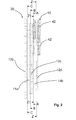
figure 2 schematically represents an elevation side view of a part of the sprocket assembly offigure 1 , in particular of a module formed by the three sprockets of smallest diameter of the aforementioned sprocket assembly; -
figure 2a schematically represents a cross section, taken according to the plane line Z-Z offigure 2 , of the last sprocket of the sprocket assembly offigure 1 and of a portion of the chain engaged thereon; -
figure 2b schematically represents a cross section, taken according to the plane line Z1-Z1 offigure 2 , of the last spacer of the sprocket assembly offigure 1 ; -
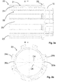
figures 3a and 3b schematically represent, respectively, an elevation side view and a cross section (taken according to the plane line III-III offigure 3a ) of a first type of the freewheel body offigure 1 ; -
figures 4a and4b schematically represent respective longitudinal sections of a first embodiment of the module of three sprockets offigure 2 mounted on the freewheel body offigures 3a and 3b (in such figures it is also possible to see a locking ring nut of the sprocket assembly on the freewheel body); -
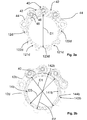
figures 5a, 5b and5c schematically represent cross sections (respectively taken according to the plane lines A-A, B-B and C-C offigure 2 ) of the module of three sprockets offigures 4a ,4b ; -
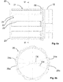
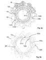
figures 6a and 6b schematically represent, respectively, an elevation side view and a cross section (taken according to the plane line VI-VI offigure 6a ) of a second type of the freewheel body offigure 1 ; -
figures 7a and7b schematically represent respective longitudinal sections of two variants of a further embodiment of the module of three sprockets offigure 2 , mounted on the freewheel body offigures 6a and 6b (in such figures it is also possible to see a locking ring nut of the sprocket assembly on the freewheel body); -
figures 8a, 8b and8c schematically represent cross sections (respectively taken according to the plane lines A-A, B-B and C-C offigure 2 ) of the module of three sprockets offigures 7a ,7b . - With initial reference to
figure 1 , a bicycle sprocket assembly in accordance with the present invention is shown. The sprocket assembly is wholly indicated with 10. - The
sprocket assembly 10 is mounted on afreewheel body 20 of a hub for a rear bicycle wheel. - The hub comprises a
hub body 15 and afreewheel body 20. Thefreewheel body 20 is coupled with thehub body 15 through any known system (not shown) through which thefreewheel body 20 can rotate idly in one direction of rotation about a rotation axis X-X and push thehub body 15 in the opposite direction of rotation. -
Figures 3a, 3b andfigures 6a, 6b respectively show two different types offreewheel bodies 20 of the conventional type available on the market, which differ in that they have different shapes and sizes. - Hereinafter and in the attached figures the parts and components that are present both in the
freewheel body 20 offigures 3a, 3b and in thefreewheel body 20 offigures 6a, 6b will be indicated with the same reference numeral. - The
freewheel body 20 has a substantially cylindrical shape and has, on the radiallyouter surface 21 thereof, a plurality oflongitudinal grooves 22 configured to be coupled with thesprocket assembly 10 to allow the rotation as a single unit of thesprocket assembly 10 and of thefreewheel body 20 about the rotation axis X-X. - The
longitudinal grooves 22 define, on the radiallyouter surface 21 of thefreewheel body 20,projections 24 andrecesses 26. Theprojections 24 compriserespective head surfaces 24a that belong to an ideal circumference having its centre on the rotation axis X-X and a diameter D4 for example equal to about 35 mm in the type offreewheel body 20 shown infigures 3a and 3b and equal to about 34.4 mm in the type offreewheel body 20 shown infigures 6a and 6b . Therecesses 26 compriserespective base surfaces 26a that belong to an ideal circumference having its centre on the rotation axis X-X and a diameter D6 for example equal to about 29 mm in the type offreewheel body 20 shown infigures 3a and 3b and equal to about 32.1 mm in the type offreewheel body 20 shown infigures 6a and 6b . - With reference to
figure 1 , thesprocket assembly 10 comprises a plurality ofsprockets 12 having decreasing diameter (reference numeral 12 is associated with just some of the sprockets shown). Reference numeral 12a indicates the sprocket having the largest diameter andreference numerals sprocket assembly 10, whereinsprocket 12c has a smaller diameter than that ofsprocket 12b and greater than that ofsprocket 12d. -
Sprocket 12d is the one which in the introductory part of this description and in the subsequent claims is also indicated as "additional sprocket" or "last sprocket", whereassprocket 12c is the one which in the introductory part of this description and in the subsequent claims is also indicated as "second-last sprocket" andsprocket 12b is the one which in the introductory part of this description and in the subsequent claims is also indicated as "third-last sprocket". - In the non-limiting example of
figure 1 thesprocket assembly 10 comprises eleven sprockets in total. - Sprocket 12a is mounted on the
freewheel body 20 and abuts against anaxial abutment element 28 of thefreewheel body 20.Sprockets sprocket 12b, are also mounted on thefreewheel body 20.Sprocket 12d, on the other hand, is mounted canti-levered with respect to thefreewheel body 20, as shown infigures 4a ,4b and7a ,7b . - The
sprocket assembly 10 further comprises a plurality ofspacers 14, each arranged between two consecutive sprockets 12 (reference numeral 14 is associated with just some of the spacers shown).Reference numeral 14a indicates the spacer arranged betweensprockets reference numeral 14b indicates the spacer arranged betweensprockets -
Spacer 14a is the one which in the introductory part of this description and in the subsequent claims is also indicated as "second-last spacer", whereasspacer 14b is the one which in the introductory part of this description and in the subsequent claims is also indicated as "last spacer". -
Spacer 14a is mounted on thefreewheel body 20 at theprojections 24, whereasspacer 14b is mounted on thefreewheel body 20 at afree end portion 23 thereof whose radially outer surface has nogrooves 22. - The attached figures show a
conventional chain 40 engaged on thesprocket 12d. Thechain 40 comprises a succession oflinks 42, each link consisting of a pair ofplates 44 facing one another and spaced apart to define an insertion space for a tooth of thesprocket 12d. Theplates 44 of alink 42 are coupled with theplates 44 of thesubsequent link 42 through arivet 46, which in turn is surrounded by abush 48 capable of rotating freely with respect to therivet 46. -
Figure 2 shows a part of thesprocket assembly 10. In particular, a sprocket module is shown comprising the three sprockets ofsmallest diameter sprocket assembly 10 and thespacers - In the non-limiting example shown in the attached figures, the
module 30 comprises asprocket 12d having ten teeth, asprocket 12c having eleven teeth and asprocket 12b having twelve teeth. -
Figures 4a ,4b andfigures 7a ,7b , respectively illustrate two different embodiments of themodule 30, which differ in that they have different shapes and sizes. - Hereinafter and in the attached figures the parts and components that are present both in the
module 30 offigures 4a ,4b and in themodule 30 offigures 7a ,7b will be indicated with the same reference numeral. -
Sprockets spacers - In alternative embodiments that are not shown, only some of
sprockets spacers - In a further alternative embodiment that is not shown,
sprockets spacers -
Figure 4a shows a first embodiment of thesprocket module 30 offigure 2 mounted on thefreewheel body 20 offigures 3a, 3b , whereasfigure 7a shows a second embodiment of thesprocket module 30 offigure 2 mounted on thefreewheel body 20 offigures 6a, 6b . - The
sprocket module 30 offigure 7a differs from thesprocket module 30 offigure 4a in that it has, being equal the outer radial dimensions ofsprockets spacers sprockets - In both the embodiments of
figure 4a and7a , a lockingring nut 50 is screwed onto thefreewheel body 20. The lockingring nut 50 comprises a substantiallycylindrical portion 52 and a substantiallyannular portion 54 that projects radially outwards with respect to the substantiallycylindrical portion 52. - The substantially
cylindrical portion 52 is provided with anouter threading 53 that is screwed onto aninner threading 25 of thefreewheel body 20. The substantiallyannular portion 54 abuts axially on thesprocket 12d, locking thesprocket assembly 10 on thefreewheel body 20. -
Figures 4b and7b show a variant of thesprocket module 30 and of the lockingring nut 50 respectively offigures 4a and7a . Thesprocket module 30 offigures 4b ,7b differs from that offigures 4a ,7a solely in that a bevel or flaring 32 is provided on a radially inner surface of thesprocket 12d. The lockingring nut 50 offigures 4b ,7b differs from that offigures 4a ,7a solely in that aradiused surface 56 is provided between the substantiallycylindrical portion 52 and the substantiallyannular portion 54. When the lockingring nut 50 offigures 4b and7b abuts on thesprocket 12d offigures 4b and7b , theradiused surface 56 is located at thebevel 32. - As shown in
figure 2a , thesprocket 12d has a plurality ofthroats 121 d, each arranged between twoconsecutive teeth 122d. Thethroats 121 d compriserespective bottom surfaces 123d substantially tangent to a circumference having a diameter D1. - In
figures 5a and8a it is possible to see thespacer 14b arranged between the sprockets 14d and 14c of the twomodules 30 respectively offigures 4a ,4b and7a ,7b . Such aspacer 14b in both cases has a substantially annular shape and a radiallyinner surface 141b that is associated with afree end portion 23 of thefreewheel body 20 offigures 3a, 3b and6a, 6b . Such a radiallyinner surface 141b is a cylindrical surface with a circular section having a diameter D7. - The
spacer 14b comprises a radiallyouter surface 142b having a diameter D2 greater than the diameter D1. - The
spacer 14b comprises a plurality of recessedareas 143b. Each recessedarea 143b is positioned at arespective throat 121d of thesprocket 12d. - The recessed
areas 143b provide the radiallyouter surface 142b of thespacer 14b with a shape that vaguely resembles the profile of a daisy. - The recessed
areas 143b comprise respective base surfaces 144b substantially tangent to a circumference having a diameter D3 substantially equal to the diameter D1. - As shown in
figures 5b and8b , thesprocket 12c has a plurality ofthroats 123c, each arranged between twoconsecutive teeth 124c. Thethroats 123c comprise respective bottom surfaces 125c substantially tangent to a circumference having a diameter D8. - The
sprocket 12c comprises a radiallyinner surface 121c having a shape matching the radiallyouter surface 21 of thefreewheel body 20. In particular, the radiallyinner surface 121c compriseslongitudinal grooves 122c configured to engage thegrooves 22 provided on the radiallyouter surface 21 of thefreewheel body 20. - As shown in
figures 5c and8c , thesprocket 12b has a plurality ofthroats 121 b, each arranged between twoconsecutive teeth 122b. - The
sprocket 12b comprises a radially inner surface (not visible infigures 5c ,8c ) of a shape matching the radiallyouter surface 21 of thefreewheel body 20, and thus provided with longitudinal grooves configured to engage thegrooves 22 provided on the radiallyouter surface 21 of thefreewheel body 20. - Again with reference to
figures 5c and8c , thespacer 14a arranged between thesprocket 12c and thesprocket 12b comprises a radiallyouter surface 142a having a radial size greater than that of the radiallyouter surface 142b of thespacer 14b. In other words, the radiallyouter surface 142a has a diameter D5 greater than the diameter D2. - The
spacer 14a comprises a radiallyinner surface 141 a having a shape matching the radiallyouter surface 21 of thefreewheel body 20. In particular, the radiallyinner surface 141a compriseslongitudinal grooves 143a configured to engage thegrooves 22 provided on the radiallyouter surface 21 of thefreewheel body 20. - The
spacer 14a comprises a plurality of recessedareas 144a. Each recessedarea 144a is positioned at arespective throat 123c of thesprocket 12c. - The recessed
areas 144a also in this case provide the radially outer surface del spacer 14a with a shape that vaguely resembles the profile of a daisy. - The recessed
areas 144a compriserespective base surfaces 145a substantially tangent to a circumference having a diameter D9 substantially equal to the diameter D8. - In an alternative embodiment that is not shown, the
spacer 14a has a radially outer surface without recessed areas. In this case, the outer radial size of thespacer 14a is smaller than or equal to the diameter D8. - In a further alternative embodiment that is not shown, the
spacer 14a is defined by a plurality of spacer elements made in one piece with, and axially projecting canti-levered from, at least one of thesprockets sprockets longitudinal grooves 122c of the radiallyinner surface 121c of thesprocket 12c (in the case in which the spacer elements are made in one piece with thesprocket 12c) or at the projections of the longitudinal grooves of the radially inner surface of thesprocket 12b (in the case in which the spacer elements are made in one piece with thesprocket 12b). - Of course, those skilled in the art can bring numerous modifications and variants to the invention described above, in order to satisfy specific and contingent requirements, all of which are in any case within the scope of protection of the present invention as defined by the following claims.
Claims (9)
- Bicycle sprocket assembly (10), comprising:- a plurality of sprockets (12) of decreasing diameter configured to be mounted on a freewheel body (20) of a bicycle hub, said plurality of sprockets (12) including a first sprocket of larger diameter (12a) and a last sprocket of smaller diameter (12d), wherein said last sprocket (14b) comprises a plurality of teeth (122d) and a plurality of throats (121 d), each throat (121 d) being arranged between two consecutive teeth (122d), said throats (121d) comprising respective bottom surfaces (123d) substantially tangent to a first circumference having a first diameter (D1);- a plurality of spacers (14) arranged between said first sprocket (12a) and said last sprocket (12d), said plurality of spacers (14) including a last spacer (14b) arranged between said last sprocket (12d) and a second-last sprocket (12c) of said plurality of sprockets (12) and having a radially inner surface (141 b) configured to be fitted onto a free end portion (23) of said freewheel body (20);characterised in that said last spacer (14b) comprises a radially outer surface (142b) having a second diameter (D2) greater than said first diameter (D1) and including a plurality of recessed areas (143b), each recessed area (143b) being positioned at a respective throat of said plurality of throats (121 d), wherein said recessed areas (143b) comprise respective base surfaces (144b) substantially tangent to a second circumference having a third diameter (D3) smaller than or equal to said first diameter (D1).
- Sprocket assembly (10) according to claim 1, wherein said last sprocket (12d) has ten teeth and said second-last sprocket (12c) has eleven or twelve teeth.
- Sprocket assembly (10) according to claim 1 or 2, wherein said last sprocket (12d) is configured to be mounted canti-levered with respect to said freewheel body (20).
- Sprocket assembly (10) according to any one of the previous claims, wherein said freewheel body (20) has a radially outer surface (21) comprising a plurality of longitudinal grooves (22) defining a plurality of projections (24) and a plurality of recesses (26), each recess (26) being arranged between two consecutive projections (24), wherein said projections (24) comprise respective head surfaces (24a) that belong to a third circumference having a fourth diameter (D4) greater than said first diameter (D1).
- Sprocket assembly (10) according to any one of the previous claims, wherein said last spacer (14b) is made in a single piece with said last sprocket (12d) and said second-last sprocket (12c).
- Sprocket assembly (10) according to claim 5, wherein said last sprocket (12d), said last spacer (14b) and said second-last sprocket (12c) are made in a single piece with a third-last sprocket (12b) of said plurality of sprockets (12).
- Sprocket assembly (10) according to claim 6, comprising a second-last spacer (14a) arranged between said second-last sprocket (12c) and said third-last sprocket (12b), wherein said second-last spacer (14a) comprises a radially outer surface (142a) having a fifth diameter (D5) greater than said second diameter (D2).
- Sprocket assembly (10) according to any one of the previous claims, wherein said radially inner surface (141b) is a cylindrical surface with a circular section.
- Sprocket assembly (10) according to any one of the previous claims, wherein said second-last sprocket (12c) comprises a radially inner surface (121c) having a shape matching the radially outer surface (21) of said freewheel body (20).
Applications Claiming Priority (1)
| Application Number | Priority Date | Filing Date | Title |
|---|---|---|---|
| ITMI20142224 | 2014-12-23 |
Publications (2)
| Publication Number | Publication Date |
|---|---|
| EP3037336A1 true EP3037336A1 (en) | 2016-06-29 |
| EP3037336B1 EP3037336B1 (en) | 2017-04-12 |
Family
ID=52355044
Family Applications (1)
| Application Number | Title | Priority Date | Filing Date |
|---|---|---|---|
| EP15196198.4A Active EP3037336B1 (en) | 2014-12-23 | 2015-11-25 | Sprocket assembly for a bicycle |
Country Status (5)
| Country | Link |
|---|---|
| US (1) | US9580144B2 (en) |
| EP (1) | EP3037336B1 (en) |
| JP (1) | JP6463665B2 (en) |
| CN (1) | CN105966543B (en) |
| TW (1) | TWI678317B (en) |
Families Citing this family (28)
| Publication number | Priority date | Publication date | Assignee | Title |
|---|---|---|---|---|
| US8820192B2 (en) | 2009-04-29 | 2014-09-02 | Race Face Prerformance Products Inc. | Bicycle crank arm and insert therefore |
| CN112517887A (en) | 2016-04-11 | 2021-03-19 | 福克斯制造有限公司 | Method for forming a bicycle front sprocket assembly |
| US11014628B2 (en) | 2017-04-28 | 2021-05-25 | Fox Factory, Inc. | Cinch direct mount 2X ring system |
| CN108974235B (en) * | 2017-05-30 | 2021-03-09 | 株式会社岛野 | Bicycle rear sprocket assembly |
| US11332213B2 (en) | 2017-05-30 | 2022-05-17 | Shimano Inc. | Bicycle rear sprocket assembly and bicycle drive train |
| US10752320B2 (en) | 2017-09-22 | 2020-08-25 | Shimano Inc. | Bicycle rear hub assembly |
| US11059541B2 (en) | 2017-05-30 | 2021-07-13 | Shimano Inc. | Bicycle hub assembly |
| TWI707802B (en) * | 2017-05-30 | 2020-10-21 | 日商島野股份有限公司 | Bicycle rear sprocket assembly and bicycle drive train |
| US10946931B2 (en) | 2017-09-22 | 2021-03-16 | Shimano Inc. | Bicycle rear sprocket assembly and bicycle drive train |
| CN112722145B (en) * | 2017-05-30 | 2022-10-25 | 株式会社岛野 | Bicycle hub assembly |
| TWI791156B (en) * | 2017-05-30 | 2023-02-01 | 日商島野股份有限公司 | Bicycle hub assembly |
| US11220309B2 (en) | 2017-05-30 | 2022-01-11 | Shimano Inc. | Bicycle rear sprocket assembly |
| US11179967B2 (en) | 2017-05-30 | 2021-11-23 | Shimano Inc. | Bicycle hub assembly |
| US10377174B2 (en) | 2017-08-09 | 2019-08-13 | Shimano Inc. | Bicycle hub assembly |
| CN111542471A (en) * | 2017-08-21 | 2020-08-14 | 劲锋铁马股份有限公司 | Bicycle cone pulley with clamping connection |
| US11072203B2 (en) * | 2018-08-22 | 2021-07-27 | Sram, Llc | Bicycle sprocket assembly |
| US12227262B2 (en) | 2018-12-07 | 2025-02-18 | Fox Factory, Inc. | Mid-sprocket assembly |
| US11359709B2 (en) * | 2018-12-18 | 2022-06-14 | Fox Factory, Inc. | Chainring |
| US11680633B2 (en) | 2019-02-08 | 2023-06-20 | Fox Factory, Inc. | Chainring |
| TWI839545B (en) * | 2019-07-30 | 2024-04-21 | 義大利商坎帕克諾羅公司 | Cogset and sub-assembly for bicycle rear wheel |
| IT201900013287A1 (en) * | 2019-07-30 | 2021-01-30 | Campagnolo Srl | Adapter for a sprocket body for a bicycle rear wheel |
| EP3960606A1 (en) * | 2020-09-01 | 2022-03-02 | SRAM Deutschland GmbH | Multi-sprocket assembly and rear wheel assembly for bicycle with derailleur |
| US11603166B2 (en) * | 2021-04-29 | 2023-03-14 | Shimano Inc. | Rear sprocket assembly and lock device |
| US11858588B2 (en) * | 2021-04-29 | 2024-01-02 | Shimano Inc. | Rear sprocket assembly and lock device |
| US12145691B2 (en) | 2021-05-25 | 2024-11-19 | Fox Factory, Inc. | Crank impact and wear protection article |
| IT202200001736A1 (en) * | 2022-02-02 | 2023-08-02 | Giuseppe Malavolta | GEARBOX AND TRANSMISSION SYSTEM OF HUMAN OR MIXED PROPULSION VEHICLE AND BICYCLE |
| US11767080B1 (en) * | 2022-07-15 | 2023-09-26 | Shimano Inc. | Rear sprocket assembly |
| EP4389577A3 (en) * | 2022-12-23 | 2024-10-23 | SRAM Deutschland GmbH | Multi-gear pinion assembly and modular system for multi-gear pinion assemblies |
Citations (4)
| Publication number | Priority date | Publication date | Assignee | Title |
|---|---|---|---|---|
| EP1439117A2 (en) * | 2003-01-17 | 2004-07-21 | Shimano Inc. | Multiple level sprocket support for a bicycle |
| US20080004143A1 (en) * | 2006-06-16 | 2008-01-03 | Shimano Inc. | Bicycle sprocket assembly |
| US20090042681A1 (en) * | 2007-08-09 | 2009-02-12 | Campagnolo S.R.L. | Set of sprockets for a bicycle rear wheel and sprocket assembly comprising such a set |
| EP2495161A1 (en) * | 2011-03-01 | 2012-09-05 | Shimano Inc. | Bicycle sprocket assembly |
Family Cites Families (7)
| Publication number | Priority date | Publication date | Assignee | Title |
|---|---|---|---|---|
| JPS5885587U (en) * | 1981-12-08 | 1983-06-10 | 株式会社シマノ | Bicycle multi-stage sprocket device |
| JP3562883B2 (en) * | 1995-09-29 | 2004-09-08 | 株式会社シマノ | Multi-stage wheels for bicycle rear wheels |
| JP2007113711A (en) * | 2005-10-21 | 2007-05-10 | Shimano Inc | Bicycle freewheel |
| US7753815B2 (en) * | 2007-01-19 | 2010-07-13 | Shimano Components (Malaysia) Sdn. Bhd. | Bicycle chain wheel assembly |
| TWM399087U (en) * | 2010-08-25 | 2011-03-01 | Orbit Design Co Ltd | Hub sleeve for fly wheels in varied specifications |
| US8641151B2 (en) * | 2010-11-12 | 2014-02-04 | Shimano Inc. | Sprocket support structure |
| TWM409185U (en) * | 2011-01-26 | 2011-08-11 | Orbit Design Co Ltd | Hub sleeve for fly wheels in varied specifications |
-
2015
- 2015-11-25 EP EP15196198.4A patent/EP3037336B1/en active Active
- 2015-11-30 TW TW104139961A patent/TWI678317B/en active
- 2015-12-09 JP JP2015239879A patent/JP6463665B2/en active Active
- 2015-12-23 CN CN201510977438.XA patent/CN105966543B/en active Active
- 2015-12-23 US US14/757,940 patent/US9580144B2/en active Active
Patent Citations (4)
| Publication number | Priority date | Publication date | Assignee | Title |
|---|---|---|---|---|
| EP1439117A2 (en) * | 2003-01-17 | 2004-07-21 | Shimano Inc. | Multiple level sprocket support for a bicycle |
| US20080004143A1 (en) * | 2006-06-16 | 2008-01-03 | Shimano Inc. | Bicycle sprocket assembly |
| US20090042681A1 (en) * | 2007-08-09 | 2009-02-12 | Campagnolo S.R.L. | Set of sprockets for a bicycle rear wheel and sprocket assembly comprising such a set |
| EP2495161A1 (en) * | 2011-03-01 | 2012-09-05 | Shimano Inc. | Bicycle sprocket assembly |
Also Published As
| Publication number | Publication date |
|---|---|
| US20160176477A1 (en) | 2016-06-23 |
| CN105966543B (en) | 2018-11-06 |
| US9580144B2 (en) | 2017-02-28 |
| JP6463665B2 (en) | 2019-02-06 |
| TW201623085A (en) | 2016-07-01 |
| CN105966543A (en) | 2016-09-28 |
| EP3037336B1 (en) | 2017-04-12 |
| JP2016117479A (en) | 2016-06-30 |
| TWI678317B (en) | 2019-12-01 |
Similar Documents
| Publication | Publication Date | Title |
|---|---|---|
| EP3037336B1 (en) | Sprocket assembly for a bicycle | |
| EP2554468B1 (en) | Bicycle sprocket assembly | |
| US8905878B2 (en) | Bicycle sprocket assembly | |
| CN107521610B (en) | Multiple bicycle sprocket assembly | |
| EP3072801B1 (en) | Chainring | |
| EP3118099B1 (en) | Bicycle multi-gear cassette | |
| EP2022713B1 (en) | Assembly of toothed wheels for a bicycle | |
| EP1671880B1 (en) | Bicycle sprocket with a laterally projecting gear change tooth | |
| EP2045181A1 (en) | Sprocket module for a bicycle and sprocket assembly comprising such a module | |
| EP1759982A2 (en) | Bicycle sprocket apparatus with reinforcement between sprockets | |
| EP2433856A1 (en) | Structural unit for a sprocket assembly of a bicycle | |
| US20180022416A1 (en) | Bicycle sprocket assembly | |
| US20090243250A1 (en) | Bicycle sprocket assembly | |
| EP3771630B1 (en) | Cogset for a bicycle rear wheel and sub-assembly of sprocket-carrying body and such cogset | |
| EP3309053B1 (en) | Pin for a crown of a bicycle crankset | |
| EP3376071A1 (en) | Toothed wheel assembly for sprocket assembly | |
| EP2594472B1 (en) | Ratchet structure of a freewheel and a hub | |
| EP2078620A1 (en) | Hub, particularly a rear hub for a bicycle | |
| US20170108058A1 (en) | Easily Replaceable One-Way Transmission Module | |
| RU2006133133A (en) | BICYCLE WHEEL TRANSMISSION | |
| SK13882003A3 (en) | Gear-wheel configuration, especially for go-kart |
Legal Events
| Date | Code | Title | Description |
|---|---|---|---|
| PUAI | Public reference made under article 153(3) epc to a published international application that has entered the european phase |
Free format text: ORIGINAL CODE: 0009012 |
|
| AK | Designated contracting states |
Kind code of ref document: A1 Designated state(s): AL AT BE BG CH CY CZ DE DK EE ES FI FR GB GR HR HU IE IS IT LI LT LU LV MC MK MT NL NO PL PT RO RS SE SI SK SM TR |
|
| AX | Request for extension of the european patent |
Extension state: BA ME |
|
| 17P | Request for examination filed |
Effective date: 20160728 |
|
| RBV | Designated contracting states (corrected) |
Designated state(s): AL AT BE BG CH CY CZ DE DK EE ES FI FR GB GR HR HU IE IS IT LI LT LU LV MC MK MT NL NO PL PT RO RS SE SI SK SM TR |
|
| GRAP | Despatch of communication of intention to grant a patent |
Free format text: ORIGINAL CODE: EPIDOSNIGR1 |
|
| INTG | Intention to grant announced |
Effective date: 20161011 |
|
| GRAJ | Information related to disapproval of communication of intention to grant by the applicant or resumption of examination proceedings by the epo deleted |
Free format text: ORIGINAL CODE: EPIDOSDIGR1 |
|
| GRAR | Information related to intention to grant a patent recorded |
Free format text: ORIGINAL CODE: EPIDOSNIGR71 |
|
| GRAS | Grant fee paid |
Free format text: ORIGINAL CODE: EPIDOSNIGR3 |
|
| GRAA | (expected) grant |
Free format text: ORIGINAL CODE: 0009210 |
|
| INTC | Intention to grant announced (deleted) | ||
| INTG | Intention to grant announced |
Effective date: 20170302 |
|
| AK | Designated contracting states |
Kind code of ref document: B1 Designated state(s): AL AT BE BG CH CY CZ DE DK EE ES FI FR GB GR HR HU IE IS IT LI LT LU LV MC MK MT NL NO PL PT RO RS SE SI SK SM TR |
|
| REG | Reference to a national code |
Ref country code: GB Ref legal event code: FG4D |
|
| REG | Reference to a national code |
Ref country code: CH Ref legal event code: EP |
|
| REG | Reference to a national code |
Ref country code: IE Ref legal event code: FG4D |
|
| REG | Reference to a national code |
Ref country code: AT Ref legal event code: REF Ref document number: 883560 Country of ref document: AT Kind code of ref document: T Effective date: 20170515 |
|
| REG | Reference to a national code |
Ref country code: DE Ref legal event code: R096 Ref document number: 602015002235 Country of ref document: DE |
|
| REG | Reference to a national code |
Ref country code: NL Ref legal event code: MP Effective date: 20170412 |
|
| REG | Reference to a national code |
Ref country code: LT Ref legal event code: MG4D |
|
| REG | Reference to a national code |
Ref country code: AT Ref legal event code: MK05 Ref document number: 883560 Country of ref document: AT Kind code of ref document: T Effective date: 20170412 |
|
| PG25 | Lapsed in a contracting state [announced via postgrant information from national office to epo] |
Ref country code: NL Free format text: LAPSE BECAUSE OF FAILURE TO SUBMIT A TRANSLATION OF THE DESCRIPTION OR TO PAY THE FEE WITHIN THE PRESCRIBED TIME-LIMIT Effective date: 20170412 |
|
| PG25 | Lapsed in a contracting state [announced via postgrant information from national office to epo] |
Ref country code: ES Free format text: LAPSE BECAUSE OF FAILURE TO SUBMIT A TRANSLATION OF THE DESCRIPTION OR TO PAY THE FEE WITHIN THE PRESCRIBED TIME-LIMIT Effective date: 20170412 Ref country code: AT Free format text: LAPSE BECAUSE OF FAILURE TO SUBMIT A TRANSLATION OF THE DESCRIPTION OR TO PAY THE FEE WITHIN THE PRESCRIBED TIME-LIMIT Effective date: 20170412 Ref country code: GR Free format text: LAPSE BECAUSE OF FAILURE TO SUBMIT A TRANSLATION OF THE DESCRIPTION OR TO PAY THE FEE WITHIN THE PRESCRIBED TIME-LIMIT Effective date: 20170713 Ref country code: NO Free format text: LAPSE BECAUSE OF FAILURE TO SUBMIT A TRANSLATION OF THE DESCRIPTION OR TO PAY THE FEE WITHIN THE PRESCRIBED TIME-LIMIT Effective date: 20170712 Ref country code: HR Free format text: LAPSE BECAUSE OF FAILURE TO SUBMIT A TRANSLATION OF THE DESCRIPTION OR TO PAY THE FEE WITHIN THE PRESCRIBED TIME-LIMIT Effective date: 20170412 Ref country code: FI Free format text: LAPSE BECAUSE OF FAILURE TO SUBMIT A TRANSLATION OF THE DESCRIPTION OR TO PAY THE FEE WITHIN THE PRESCRIBED TIME-LIMIT Effective date: 20170412 Ref country code: LT Free format text: LAPSE BECAUSE OF FAILURE TO SUBMIT A TRANSLATION OF THE DESCRIPTION OR TO PAY THE FEE WITHIN THE PRESCRIBED TIME-LIMIT Effective date: 20170412 |
|
| REG | Reference to a national code |
Ref country code: FR Ref legal event code: PLFP Year of fee payment: 3 |
|
| PG25 | Lapsed in a contracting state [announced via postgrant information from national office to epo] |
Ref country code: SE Free format text: LAPSE BECAUSE OF FAILURE TO SUBMIT A TRANSLATION OF THE DESCRIPTION OR TO PAY THE FEE WITHIN THE PRESCRIBED TIME-LIMIT Effective date: 20170412 Ref country code: BG Free format text: LAPSE BECAUSE OF FAILURE TO SUBMIT A TRANSLATION OF THE DESCRIPTION OR TO PAY THE FEE WITHIN THE PRESCRIBED TIME-LIMIT Effective date: 20170712 Ref country code: PL Free format text: LAPSE BECAUSE OF FAILURE TO SUBMIT A TRANSLATION OF THE DESCRIPTION OR TO PAY THE FEE WITHIN THE PRESCRIBED TIME-LIMIT Effective date: 20170412 Ref country code: LV Free format text: LAPSE BECAUSE OF FAILURE TO SUBMIT A TRANSLATION OF THE DESCRIPTION OR TO PAY THE FEE WITHIN THE PRESCRIBED TIME-LIMIT Effective date: 20170412 Ref country code: IS Free format text: LAPSE BECAUSE OF FAILURE TO SUBMIT A TRANSLATION OF THE DESCRIPTION OR TO PAY THE FEE WITHIN THE PRESCRIBED TIME-LIMIT Effective date: 20170812 Ref country code: RS Free format text: LAPSE BECAUSE OF FAILURE TO SUBMIT A TRANSLATION OF THE DESCRIPTION OR TO PAY THE FEE WITHIN THE PRESCRIBED TIME-LIMIT Effective date: 20170412 |
|
| REG | Reference to a national code |
Ref country code: DE Ref legal event code: R097 Ref document number: 602015002235 Country of ref document: DE |
|
| PG25 | Lapsed in a contracting state [announced via postgrant information from national office to epo] |
Ref country code: RO Free format text: LAPSE BECAUSE OF FAILURE TO SUBMIT A TRANSLATION OF THE DESCRIPTION OR TO PAY THE FEE WITHIN THE PRESCRIBED TIME-LIMIT Effective date: 20170412 Ref country code: CZ Free format text: LAPSE BECAUSE OF FAILURE TO SUBMIT A TRANSLATION OF THE DESCRIPTION OR TO PAY THE FEE WITHIN THE PRESCRIBED TIME-LIMIT Effective date: 20170412 Ref country code: EE Free format text: LAPSE BECAUSE OF FAILURE TO SUBMIT A TRANSLATION OF THE DESCRIPTION OR TO PAY THE FEE WITHIN THE PRESCRIBED TIME-LIMIT Effective date: 20170412 Ref country code: DK Free format text: LAPSE BECAUSE OF FAILURE TO SUBMIT A TRANSLATION OF THE DESCRIPTION OR TO PAY THE FEE WITHIN THE PRESCRIBED TIME-LIMIT Effective date: 20170412 Ref country code: SK Free format text: LAPSE BECAUSE OF FAILURE TO SUBMIT A TRANSLATION OF THE DESCRIPTION OR TO PAY THE FEE WITHIN THE PRESCRIBED TIME-LIMIT Effective date: 20170412 |
|
| PLBE | No opposition filed within time limit |
Free format text: ORIGINAL CODE: 0009261 |
|
| STAA | Information on the status of an ep patent application or granted ep patent |
Free format text: STATUS: NO OPPOSITION FILED WITHIN TIME LIMIT |
|
| PG25 | Lapsed in a contracting state [announced via postgrant information from national office to epo] |
Ref country code: SM Free format text: LAPSE BECAUSE OF FAILURE TO SUBMIT A TRANSLATION OF THE DESCRIPTION OR TO PAY THE FEE WITHIN THE PRESCRIBED TIME-LIMIT Effective date: 20170412 |
|
| 26N | No opposition filed |
Effective date: 20180115 |
|
| PG25 | Lapsed in a contracting state [announced via postgrant information from national office to epo] |
Ref country code: MC Free format text: LAPSE BECAUSE OF FAILURE TO SUBMIT A TRANSLATION OF THE DESCRIPTION OR TO PAY THE FEE WITHIN THE PRESCRIBED TIME-LIMIT Effective date: 20170412 |
|
| PG25 | Lapsed in a contracting state [announced via postgrant information from national office to epo] |
Ref country code: LU Free format text: LAPSE BECAUSE OF NON-PAYMENT OF DUE FEES Effective date: 20171125 |
|
| REG | Reference to a national code |
Ref country code: BE Ref legal event code: MM Effective date: 20171130 |
|
| REG | Reference to a national code |
Ref country code: IE Ref legal event code: MM4A |
|
| PG25 | Lapsed in a contracting state [announced via postgrant information from national office to epo] |
Ref country code: MT Free format text: LAPSE BECAUSE OF NON-PAYMENT OF DUE FEES Effective date: 20171125 |
|
| PG25 | Lapsed in a contracting state [announced via postgrant information from national office to epo] |
Ref country code: IE Free format text: LAPSE BECAUSE OF NON-PAYMENT OF DUE FEES Effective date: 20171125 |
|
| PG25 | Lapsed in a contracting state [announced via postgrant information from national office to epo] |
Ref country code: BE Free format text: LAPSE BECAUSE OF NON-PAYMENT OF DUE FEES Effective date: 20171130 |
|
| PG25 | Lapsed in a contracting state [announced via postgrant information from national office to epo] |
Ref country code: HU Free format text: LAPSE BECAUSE OF FAILURE TO SUBMIT A TRANSLATION OF THE DESCRIPTION OR TO PAY THE FEE WITHIN THE PRESCRIBED TIME-LIMIT; INVALID AB INITIO Effective date: 20151125 |
|
| REG | Reference to a national code |
Ref country code: CH Ref legal event code: PL |
|
| PG25 | Lapsed in a contracting state [announced via postgrant information from national office to epo] |
Ref country code: LI Free format text: LAPSE BECAUSE OF NON-PAYMENT OF DUE FEES Effective date: 20181130 Ref country code: CH Free format text: LAPSE BECAUSE OF NON-PAYMENT OF DUE FEES Effective date: 20181130 |
|
| PG25 | Lapsed in a contracting state [announced via postgrant information from national office to epo] |
Ref country code: SI Free format text: LAPSE BECAUSE OF FAILURE TO SUBMIT A TRANSLATION OF THE DESCRIPTION OR TO PAY THE FEE WITHIN THE PRESCRIBED TIME-LIMIT Effective date: 20170412 |
|
| PG25 | Lapsed in a contracting state [announced via postgrant information from national office to epo] |
Ref country code: CY Free format text: LAPSE BECAUSE OF FAILURE TO SUBMIT A TRANSLATION OF THE DESCRIPTION OR TO PAY THE FEE WITHIN THE PRESCRIBED TIME-LIMIT Effective date: 20170412 |
|
| PG25 | Lapsed in a contracting state [announced via postgrant information from national office to epo] |
Ref country code: MK Free format text: LAPSE BECAUSE OF FAILURE TO SUBMIT A TRANSLATION OF THE DESCRIPTION OR TO PAY THE FEE WITHIN THE PRESCRIBED TIME-LIMIT Effective date: 20170412 |
|
| PG25 | Lapsed in a contracting state [announced via postgrant information from national office to epo] |
Ref country code: TR Free format text: LAPSE BECAUSE OF FAILURE TO SUBMIT A TRANSLATION OF THE DESCRIPTION OR TO PAY THE FEE WITHIN THE PRESCRIBED TIME-LIMIT Effective date: 20170412 |
|
| PG25 | Lapsed in a contracting state [announced via postgrant information from national office to epo] |
Ref country code: PT Free format text: LAPSE BECAUSE OF FAILURE TO SUBMIT A TRANSLATION OF THE DESCRIPTION OR TO PAY THE FEE WITHIN THE PRESCRIBED TIME-LIMIT Effective date: 20170412 |
|
| PG25 | Lapsed in a contracting state [announced via postgrant information from national office to epo] |
Ref country code: AL Free format text: LAPSE BECAUSE OF FAILURE TO SUBMIT A TRANSLATION OF THE DESCRIPTION OR TO PAY THE FEE WITHIN THE PRESCRIBED TIME-LIMIT Effective date: 20170412 |
|
| GBPC | Gb: european patent ceased through non-payment of renewal fee |
Effective date: 20191125 |
|
| PG25 | Lapsed in a contracting state [announced via postgrant information from national office to epo] |
Ref country code: GB Free format text: LAPSE BECAUSE OF NON-PAYMENT OF DUE FEES Effective date: 20191125 |
|
| P01 | Opt-out of the competence of the unified patent court (upc) registered |
Effective date: 20230516 |
|
| PGFP | Annual fee paid to national office [announced via postgrant information from national office to epo] |
Ref country code: DE Payment date: 20251128 Year of fee payment: 11 |
|
| PGFP | Annual fee paid to national office [announced via postgrant information from national office to epo] |
Ref country code: IT Payment date: 20251119 Year of fee payment: 11 |
|
| PGFP | Annual fee paid to national office [announced via postgrant information from national office to epo] |
Ref country code: FR Payment date: 20251125 Year of fee payment: 11 |