EP3960606A1 - Multi-sprocket assembly and rear wheel assembly for bicycle with derailleur - Google Patents
Multi-sprocket assembly and rear wheel assembly for bicycle with derailleur Download PDFInfo
- Publication number
- EP3960606A1 EP3960606A1 EP21020407.9A EP21020407A EP3960606A1 EP 3960606 A1 EP3960606 A1 EP 3960606A1 EP 21020407 A EP21020407 A EP 21020407A EP 3960606 A1 EP3960606 A1 EP 3960606A1
- Authority
- EP
- European Patent Office
- Prior art keywords
- assembly
- driver
- pinion
- section
- smallest
- Prior art date
- Legal status (The legal status is an assumption and is not a legal conclusion. Google has not performed a legal analysis and makes no representation as to the accuracy of the status listed.)
- Pending
Links
Images


Classifications
-
- B—PERFORMING OPERATIONS; TRANSPORTING
- B62—LAND VEHICLES FOR TRAVELLING OTHERWISE THAN ON RAILS
- B62M—RIDER PROPULSION OF WHEELED VEHICLES OR SLEDGES; POWERED PROPULSION OF SLEDGES OR SINGLE-TRACK CYCLES; TRANSMISSIONS SPECIALLY ADAPTED FOR SUCH VEHICLES
- B62M9/00—Transmissions characterised by use of an endless chain, belt, or the like
- B62M9/04—Transmissions characterised by use of an endless chain, belt, or the like of changeable ratio
- B62M9/06—Transmissions characterised by use of an endless chain, belt, or the like of changeable ratio using a single chain, belt, or the like
- B62M9/10—Transmissions characterised by use of an endless chain, belt, or the like of changeable ratio using a single chain, belt, or the like involving different-sized wheels, e.g. rear sprocket chain wheels selectively engaged by the chain, belt, or the like
- B62M9/12—Transmissions characterised by use of an endless chain, belt, or the like of changeable ratio using a single chain, belt, or the like involving different-sized wheels, e.g. rear sprocket chain wheels selectively engaged by the chain, belt, or the like the chain, belt, or the like being laterally shiftable, e.g. using a rear derailleur
-
- B—PERFORMING OPERATIONS; TRANSPORTING
- B62—LAND VEHICLES FOR TRAVELLING OTHERWISE THAN ON RAILS
- B62M—RIDER PROPULSION OF WHEELED VEHICLES OR SLEDGES; POWERED PROPULSION OF SLEDGES OR SINGLE-TRACK CYCLES; TRANSMISSIONS SPECIALLY ADAPTED FOR SUCH VEHICLES
- B62M9/00—Transmissions characterised by use of an endless chain, belt, or the like
- B62M9/04—Transmissions characterised by use of an endless chain, belt, or the like of changeable ratio
- B62M9/06—Transmissions characterised by use of an endless chain, belt, or the like of changeable ratio using a single chain, belt, or the like
-
- B—PERFORMING OPERATIONS; TRANSPORTING
- B62—LAND VEHICLES FOR TRAVELLING OTHERWISE THAN ON RAILS
- B62K—CYCLES; CYCLE FRAMES; CYCLE STEERING DEVICES; RIDER-OPERATED TERMINAL CONTROLS SPECIALLY ADAPTED FOR CYCLES; CYCLE AXLE SUSPENSIONS; CYCLE SIDE-CARS, FORECARS, OR THE LIKE
- B62K25/00—Axle suspensions
- B62K25/02—Axle suspensions for mounting axles rigidly on cycle frame or fork, e.g. adjustably
-
- B—PERFORMING OPERATIONS; TRANSPORTING
- B62—LAND VEHICLES FOR TRAVELLING OTHERWISE THAN ON RAILS
- B62M—RIDER PROPULSION OF WHEELED VEHICLES OR SLEDGES; POWERED PROPULSION OF SLEDGES OR SINGLE-TRACK CYCLES; TRANSMISSIONS SPECIALLY ADAPTED FOR SUCH VEHICLES
- B62M9/00—Transmissions characterised by use of an endless chain, belt, or the like
- B62M9/04—Transmissions characterised by use of an endless chain, belt, or the like of changeable ratio
- B62M9/06—Transmissions characterised by use of an endless chain, belt, or the like of changeable ratio using a single chain, belt, or the like
- B62M9/10—Transmissions characterised by use of an endless chain, belt, or the like of changeable ratio using a single chain, belt, or the like involving different-sized wheels, e.g. rear sprocket chain wheels selectively engaged by the chain, belt, or the like
- B62M9/12—Transmissions characterised by use of an endless chain, belt, or the like of changeable ratio using a single chain, belt, or the like involving different-sized wheels, e.g. rear sprocket chain wheels selectively engaged by the chain, belt, or the like the chain, belt, or the like being laterally shiftable, e.g. using a rear derailleur
- B62M9/121—Rear derailleurs
- B62M9/125—Mounting the derailleur on the frame
-
- F—MECHANICAL ENGINEERING; LIGHTING; HEATING; WEAPONS; BLASTING
- F16—ENGINEERING ELEMENTS AND UNITS; GENERAL MEASURES FOR PRODUCING AND MAINTAINING EFFECTIVE FUNCTIONING OF MACHINES OR INSTALLATIONS; THERMAL INSULATION IN GENERAL
- F16H—GEARING
- F16H55/00—Elements with teeth or friction surfaces for conveying motion; Worms, pulleys or sheaves for gearing mechanisms
- F16H55/02—Toothed members; Worms
- F16H55/30—Chain-wheels
Definitions
- the present invention relates to a multi-sprocket assembly for a derailleur bicycle that includes a multi-sprocket assembly and a plug assembly.
- the invention also relates to a rear wheel assembly for a derailleur bicycle having a multi-sprocket assembly.
- a rear wheel assembly for a derailleur bicycle typically includes a multiple sprocket assembly coupled or coupleable to the rear wheel hub via a driver. Pinions of the multiple pinion assembly are torque-transmittingly connected to the driver.
- a locking ring is conventionally used to fix the pinions against axial displacement. Such a locking ring has an external thread on one end area and a radially extending projection on an opposite end area. When the rear wheel assembly is assembled, the male thread of the lock ring engages a female thread of the driver so that the overhang abuts an outside surface of the smallest sprocket. In this way, the locking ring fixes the sprockets of the multiple sprocket assembly against axial displacement.
- the driver is in torque-transmitting engagement with the rear wheel hub via a one-way clutch and allows torque transmission in one direction of rotation (drive direction), while the driver is rotationally decoupled from the rear wheel hub in the other direction by a free-wheel mechanism.
- the rear wheel hub When assembled, the rear wheel hub is connected to a rear wheel axle which is attached at its opposite ends to a respective dropout of a bicycle frame.
- the bicycle frame thus defines an installation width between its two dropouts and their inner distance to each other for all components to be attached to the rear wheel hub, such as a wheel, a driver, a multiple sprocket arrangement, a hub end cap and possibly other components, for example for attaching a rear derailleur.
- the geometry of the driver sets limits with conventional solutions.
- the pinions are attached to the radial outer circumference of the driver, as a result of which a minimum inner diameter (root circle) of the pinions is already predetermined by the outer diameter of the driver.
- the smallest sprocket with 11 teeth can just be attached to the sprocket assembly and fixed against axial displacement by the locking ring.
- the driver includes a first tubular member that is attachable to the bicycle hub with a freewheel mechanism.
- a smaller diameter second tubular member may be coupled to the axially outer end of the first tubular member.
- the second tubular element has an external diameter smaller than that of the first tubular element and allows a pinion with 10 teeth to be fixed and radially supported thereon.
- the housing and the radial support of three pinions on the second tubular member are shown.
- a locking ring provided with an internal thread engages with an external thread of the second tubular element in such a way that the locking ring bears against an outside surface of the smallest sprocket.
- the two pinions with a smaller diameter are connected to each other via a first connection section and to a smallest pinion arranged on the driver via a further connection section.
- the two pinions with a smaller inner diameter are cantilevered.
- a blocking element is provided which fixes the pinion against axial displacement.
- the locking member includes a male thread engageable with a female thread of the driver, a shank portion on which the two smaller-diameter pinions are received, and a radially extending projection.
- the blocking element is adapted to accommodate pinions with a smaller diameter, in that the outer diameter of the shank section is larger than a nominal diameter of the external thread and the projection extends radially outwards to such an extent that it rests against the smallest pinion and can absorb axial forces exerted by it.
- This object is achieved by a multiple sprocket assembly for a bicycle with derailleur gears having the features of claim 1. Furthermore, this object is achieved by a rear wheel assembly for a bicycle with derailleur gears having the features of claim 16.
- a multi-sprocket assembly for a rear wheel assembly for a derailleur bicycle includes a multi-sprocket assembly and a plug assembly.
- the multiple sprocket assembly is configured for torque-transmitting coupling to a driver of the rear wheel assembly and includes at least 11 sprockets with differing numbers of teeth.
- the multiple pinion subassembly is designed in such a way that when the driver is assembled with the multiple pinion subassembly, at least two of the smallest pinions are fixed axially to the driver via the locking screw arrangement.
- the locking screw arrangement has a shank section for receiving at least one of the at least two smallest sprockets.
- the shank section is provided at its one end area with an axially outer stop section. Furthermore, at least one external thread is associated with the shaft section on its opposite end region, with which the screw plug arrangement can be screwed into an associated internal thread for fixing the screw plug arrangement.
- the solution according to the invention provides that the external thread assigned to the shank section has an outside diameter that is larger than the outside diameter of the shank section in that area in which at least one of the at least two smallest sprockets is accommodated.
- the solution according to the invention provides that at least two of the smallest sprockets, ie at least two of the sprockets with the smallest number of teeth, are axially fixed or can be fixed to the other sprockets of the multiple sprocket arrangement by the locking screw arrangement.
- This allows the multiple pinion assembly to include more pinions compared to a conventional attachment of the pinions to an outer peripheral surface of the driver.
- the solution according to the invention provides a possibility of overcoming the limitation of the inner diameter of the smallest sprocket caused by the outer circumference of the driver, at least for the at least one sprocket that is accommodated on the shaft section of the locking screw arrangement.
- the shaft section has a smaller outside diameter than the outside diameter of the driver having.
- the external thread assigned to the shank section which can engage in an internal thread of the driver and is preferably designed as a ring element, is used to fix the locking screw arrangement on a driver or a multiple pinion arrangement.
- the external thread associated with the shank section thus serves as a link between the shank section and the internal thread of the driver. Consequently, the internal thread of the driver can be used to fix the locking screw assembly to the driver.
- a larger transmission ratio of the derailleur can be achieved.
- the at least one of the at least two smallest sprockets which is accommodated on the shaft section, can be designed to be cantilevered. i.e. there may be a radial spacing between the shank portion and the at least one sprocket received thereon or all of the sprockets received thereon.
- a smallest sprocket refers to that sprocket that has the smallest number of teeth. If several smallest sprockets are mentioned, this means those adjacent sprockets with the smallest number of teeth. In one embodiment of the invention, a smallest pinion has, for example, 10 teeth. However, the smallest sprockets with 9 or 8 teeth are also possible. The smaller the number of teeth, the greater the transmission ratio of the derailleur that can be achieved with the multiple sprocket arrangement with the largest sprocket remaining unchanged. The minimum number of teeth is limited by the minimum possible inner diameter of the smallest sprocket in connection with the bicycle chain used.
- the multiple sprocket assembly of the present invention may include a multiple sprocket assembly having 12 sprockets or even 13 sprockets or more.
- the largest sprocket can have a number of teeth of at least 48, in particular 50, 51 or 52 teeth.
- the axially outer stop section can be set up to absorb forces that act axially outwards on the screw plug arrangement.
- the axially outward direction is defined as extending from a bicycle center plane orthogonal to the axis of rotation of the multi-sprocket assembly and passing through a midpoint between two opposite frame dropouts of a bicycle frame, toward the frame dropout closer to the multi-sprocket assembly.
- the axially inward direction is opposite to the axially outward direction.
- a radially outward direction is orthogonal to and away from an axis of rotation of the multi-sprocket assembly.
- the radially inward direction is opposite to the radially outward direction.
- the internal thread, into which the external thread associated with the shank section can engage in order to fix the locking screw arrangement, can be arranged on the driver.
- this internal thread can be arranged on a radially inner area of the multiple pinion arrangement.
- the interlocking threads are designed in such a way that there is sufficient overlap to transfer the forces that occur during operation.
- At least one pinion is accommodated on the shaft section together with a connecting section assigned to this pinion.
- two sprockets can be accommodated on the shaft section with a connecting section connecting these two sprockets.
- a length from an inner side surface of the external thread associated with the shank section to an inner side surface of the axially outer stop section can be between 3.2 mm and 5.0 mm.
- the connecting portion may be a flange portion or a retaining bolt.
- the connecting portion may be made integral with or attached to the adjacent sprockets.
- the axial length of the plug assembly may be less than a distance between four or three adjacent sprockets measured from an inside surface of the largest of the four or three sprockets and an outside surface of the smallest of the four or three sprockets.
- an outside diameter of the axially outer stop section is smaller than, just as large as or larger than an outside diameter of the external thread associated with the shank section. It goes without saying that a smaller design of the stop section saves space, but should nevertheless be sufficiently stable to absorb axial forces occurring during operation.
- the outer diameter of the axially outer stop section can also be larger than the outer diameter of the shank section. This creates an undercut on the outer circumference of the locking screw arrangement.
- an undercut is understood to mean that there is an area whose outer peripheral surface is delimited by two axial stops with a larger diameter. Training An undercut allows the locking screw arrangement to provide a sufficiently large external thread, a shank area with a smaller diameter than the outer diameter of the driver and an axial fixation of pinions accommodated on the shank section in a very space-saving design.
- the external thread associated with the shank section is formed integrally on the shank section or is produced integrally with it.
- the axially outer stop section can also be formed integrally on the shaft section or be manufactured integrally with it.
- At least one of the male threads and the stop portion may be formed during assembly of the multiple sprocket assembly after the at least one of the at least two smallest sprockets is received in or on the shank portion.
- the molding can be done by means of laser welding, friction welding, soldering, gluing, pressing, pins and/or folding.
- the locking screw arrangement can therefore have at least one joint which is formed, for example, by means of the above molding methods.
- the joint may be orthogonal or parallel to the axis of rotation of the multiple pinion assembly.
- an additive manufacturing method for example a 3D printing method, is possible according to the invention.
- the axially outer stop section and/or the external thread associated with the shank section can be manufactured and formed integrally with the shank section.
- the diameter of the axially outer stop section and/or the external thread is increased relative to the shank section.
- the formed external thread assigned to the shank section and/or the axially outer stop section have an outside diameter that is larger than the outside diameter of the shank section in the area in which the at least two smallest sprockets are accommodated.
- the axially outer stop section is produced integrally with the shank section and with the same outside diameter.
- the axially outer stop section and/or the threaded section is reshaped so that its outer diameter increases and its axial length decreases at the same time.
- the material to be formed is pushed from the axial direction into the radial direction.
- the reshaping can be done, for example, by flanging.
- the external thread assigned to the shank section can also be produced inexpensively in this way. After forming must the enlarged outside diameter of the external thread assigned to the shank section can only be provided with an external thread in a third step.
- the at least two smallest pinions are pushed onto the shank section before the forming.
- the at least two smallest sprockets are fixed in the axial direction on the shank section by the enlarged outer diameter of the axially outer stop section and/or the external thread assigned to the shank section.
- the axially outer stop section can be formed by a plurality of snap hooks, which are distributed over the outer circumference of the locking screw arrangement, the shank section and/or the snap hooks having such elasticity that a pinion or a combination of several pinions with an inner diameter smaller than the outer diameter of the snap hooks, can be pushed over the snap hooks, so that this or these are accommodated in the area of the shaft section.
- the locking screw arrangement can already be formed integrally before the assembly of the multiple pinion assembly. This simplifies the assembly process of the multi-pinion assembly.
- the axially outer stop section can be detached from the shank section and is in the form of a securing element which can be connected to the shank section, for example engaging in a groove formed in the end region of the shank section.
- the securing element can be a ring element, for example a snap ring.
- the larger-diameter thread and/or stop section of the screw plug can be segmented.
- the segmented design of the locking screw and at least the smallest sprocket allows a bayonet lock-like connection between the smallest sprocket and the locking screw.
- the two parts are connected to one another by plugging them into one another and twisting them relative to one another.
- a further embodiment variant of the invention relates to a two-part locking screw arrangement which comprises a first and a second component.
- the two components can be detachable from each other.
- the external thread assigned to the shank section can be detached from the shank section.
- Possible connection means include screw connections, plug connections, locking mechanisms and other detachable connection means.
- the first component can have a first tool interface and the second component can have a second tool interface.
- the tool interfaces can be arranged radially inside on an inner peripheral surface of the first or second component.
- the two tool interfaces can be identical or different from each other to allow engagement of the same or two different tools. In this way, both components can be handled independently using the appropriate tool. For example, one of the components can be connected to the driver during assembly and the two components can then be connected. Alternatively, the two components can first be connected to one another and then both components can be connected together to the driver. It goes without saying that the components can be dismantled from the driver in the same way.
- the tool interfaces allow non-destructive assembly and disassembly of the two components from the driver in a state in which the non-self-supporting pinions of the multiple pinion arrangement are coupled to the driver.
- the external thread assigned to the shank section can be comprised by the first component, and the axially outer stop section can be comprised by the second component.
- the first and the second component can be screwed together, for example.
- a cartridge tool known in the art having an outside diameter greater than 22 mm may torque-transmittingly engage the tool interface of the two-piece or one-piece locking screw assembly.
- the first component can have a first connection thread, which is set up to engage in a complementary second connection thread of the second component.
- the connecting threads can be arranged at different positions, for example between the shank section and the external thread associated therewith or in the region of the shank section or between the shank section and the stop section.
- the connecting thread of the first component can be an external thread and the complementary connecting thread of the second component can be an internal thread.
- the first connection thread of the first component can be an internal thread and the complementary second connection thread of the second component can be an external thread.
- the locking screw arrangement is designed to engage in an internal thread with the external thread associated with the shank section.
- the internal thread can be arranged on the driver, on whose outer peripheral surface pinions of the multiple pinion arrangement are arranged.
- the at least one pinion received thereon has any angular position relative to the pinions arranged on the outer peripheral surface of the multiple pinion arrangement.
- a predetermined angular positioning of the tooth formations on the sprockets to each other when assembled is desirable in order to ensure smooth shifting operations of the bicycle chain between the individual sprockets that are hardly noticeable to the cyclist and consequently the most continuous possible torque transmission.
- threaded connections do not allow precise angular positioning of the elements that are screwed together, especially in high-volume products.
- the components are occasionally detached from one another for maintenance or repair purposes, which makes it even more difficult to precisely reposition the individual threaded connections to one another after they have been reassembled.
- the angular position of the smallest or the two smallest pinions accommodated on the shaft section can be adjusted independently of the thread position. This means that the smallest or the two smallest sprockets can be rotatable relative to the shank portion of the plug assembly.
- the angular position of the smallest sprocket, preferably the at least two smallest sprockets, relative to sprockets directly coupled to the driver can be fixed by suitable fixing means before, during or after screwing the locking screw arrangement into the driver.
- the fixing means can, for example, couple the pinions held by the locking screw arrangement in a rotationally fixed manner to other pinions of the multiple pinion assembly.
- the smallest sprocket coupled to the driver and the adjacent next smaller sprocket received by the locking screw assembly may each have a collar with teeth and indentations that can engage and set a desired angular position of the sprockets relative to one another.
- the outer diameter of the external thread assigned to the shank section is larger than an inner diameter of the smallest pinion of the multiple pinion arrangement.
- the shank portion may be configured to accommodate one or two sprockets having an inner diameter of 27.0 mm to 28.2 mm, preferably 27.2 +/- 0.2 mm.
- the shank portion may be configured to receive a pinion having an inner diameter of approximately 24 mm.
- the shank section can include a step, so that it is suitable for receiving two sprockets that have the specified larger or smaller inner diameter. Sprockets with the specified inner diameters are suitable for having 10 or 9 teeth with a suitable spacing for engaging in the bicycle chain.
- the two smallest sprockets of the multiple sprocket arrangement can be integrally connected to one another in the assembled state. In this way, the angular positioning of these two smallest sprockets relative to each other is fixed.
- the integral connection can be achieved by forming the two smallest sprockets in one piece or by molding the sprockets together, for which purpose the molding methods discussed above can be used. Alternatively, an additive manufacturing method, for example a 3D printing method, is possible according to the invention.
- the connecting section is preferably arranged between the pinions. Joints created during molding can run parallel or orthogonally to the axis of rotation of the multiple sprocket arrangement and can be arranged adjacent to the connecting section connecting the two sprockets.
- the three smallest sprockets of the multiple sprocket arrangement can also be integrally connected to one another in the assembled state. Joints can be provided in the area of the shank section, between the shank section and the associated external thread and/or between the shank section and the stop section lying axially on the outside.
- the two or three smallest sprockets of the multiple sprocket assembly may be releasably connected together and have intermeshing teeth and associated indentations.
- the pinions In a state in which the teeth are engaged with the associated notches, the pinions are non-rotatably connected to each other.
- the screw plug arrangement can have a tool interface located radially on the inside, which enables a tool to engage in a torque-transmitting manner.
- An inner diameter of the tool interface can be between 22.6 mm and 23.6 mm, preferably 21.6 +0.4/-0.6 mm.
- the smallest pinion of the multiple pinion arrangement can have a radial and axial recess on its axially outer end face, which is designed in such a way that the axially outer stop section can engage in it.
- the outer side surface of the smallest pinion can be axially further out than an end face of the axial external stop section.
- the outside surface of the smallest sprocket may be flush with the face of the axially outside stop portion.
- the axially outer stop portion can protrude less than a maximum of 0.5 mm, preferably less than 0.2 mm, axially outwards from the outer side surface of the smallest sprocket. It goes without saying that the above statements apply equally to all embodiments of the axially outer stop section.
- an intermediate element e.g. a sheet metal ring or a plastic ring, can be inserted in the area of the recess between the smallest pinion and the locking screw arrangement, in order to reduce the friction occurring at the contact points.
- the locking screw arrangement can be made in one piece and can be provided as a 3D-printed component with the at least one pinion mounted on the shaft section.
- the locking screw arrangement can be manufactured integrally and the pinions can be printed radially outside of the locking screw arrangement in such a way that they are accommodated in the region of the shank section. i.e. the locking screw assembly and the pinions housed thereon may be integrally manufactured.
- other sprockets of the multiple sprocket arrangement can also be produced as a 3D-printed component.
- a rear wheel assembly for a derailleur bicycle includes a rear wheel hub positionable between two opposing frame portions of a bicycle frame, a driver rotatably coupled to the rear wheel hub, and a multiple pinion gear assembly configured as set forth above.
- the multi-pinion arrangement of the multi-pinion assembly is non-rotatably coupled or coupleable to the driver.
- the driver to which the multi-pinion assembly is or can be coupled may be a standard driver known in the art and marketed under the name Hyperglide® driver, or HG driver for short.
- the multi-pinion assembly according to the invention can therefore be used together with a conventional driver type, which is cheap and readily available due to its large production numbers and its widespread use.
- the driver can have a driver profile on a first driver region of its radial outer surface, which is arranged axially outwards from the driver stop along a first axial driver length.
- the first axial driver length may be less than a second axial driver length extending from the driver stop to the axially outer face of the driver.
- the driver can be free of carrier profiles on a second driver region of its radial outer surface, which is adjacent to the axially outer end face of the driver.
- the impeller can have an opening which extends radially outwards from a central impeller axis and axially inwards from the axially outer end face of the impeller, wherein the opening can have the internal thread on its radial inner surface.
- Characteristic dimensions of the driver can be as follows.
- the first axial driver length of the driver from the driver stop to the end of the flighting can be greater than 32.9 mm and is preferably 33.2 +/- 0.4 mm.
- the second axial driver length of the driver from the driver stop to the axially outer face of the driver may be greater than 34.2 mm and is preferably 34.9 +/- 0.3 mm.
- a first driver outer diameter of the driver in the first driver region along the first driver axial length of the driver may be greater than 34.2 mm and is preferably 34.5 +/- 0.2 mm.
- a second driver outer diameter of the driver in the second driver region adjacent the axially outer face of the driver may be greater than 31.4 mm and is preferably 32.1+0.4/-0.2 mm.
- a first nominal impeller diameter of the impeller axially adjacent its axially outer face may be greater than 29.8 mm and is preferably 30.6 +/- 0.2 mm.
- the multi-pinion assembly can be designed such that, in the assembled state, a first distance in the axial direction from the driver stop to the outside surface of the smallest pinion is greater than 38.0 mm, preferably greater than 39.1 mm, more preferably 39 .9 +/- 0.2mm. Additionally or alternatively, a second distance in the axial direction from the axially outer face of the driver to an outer side surface of the smallest sprocket may be greater than 4.0 mm and is preferably 5.0 +/- 0.2 mm.
- the installation width available for installing the multiple pinion assembly in connection with the use of a multiple pinion assembly can be as large as possible Number of teeth are used particularly advantageously.
- This advantageous use of space is reflected in the first and second space use factors defined below, which relate the dimensions of the driver to those dimensions which result from the locking screw arrangement attached to the driver and the at least one pinion accommodated thereon.
- the available installation width for all components to be attached to the rear wheel hub is at least 142 mm.
- the installation width is the distance from an outside of a left hub end cap adjacent to the frame section to an outside of the right hub end cap adjacent to the frame section.
- the first space utilization factor which results from the ratio of the second driver length and the second distance, can be in a range between 5 and 10.
- the second space utilization factor which results from the ratio of the first driver length and the second distance, can be in a range between 5 and 10.
- the invention also relates to a method for assembling a rear wheel assembly.
- Such a method for assembling a rear wheel assembly can include the following steps: the step of connecting at least two sprockets with the smallest number of teeth of a multiple sprocket arrangement to one another, the step of connecting the at least two connected sprockets with a locking screw so that the at least two sprockets can be rotated about a central axis of the plug screw, the step of attaching the plug screw to a driver by engaging an external thread of the plug screw assembly with an internal thread of the driver, the step of aligning the two connected sprockets with respect to sprockets with larger numbers of teeth connected to a driver, and the step of fixing the two aligned linked sprockets to a sprocket linked to the driver by fasteners.
- figure 1 shows a perspective view of a rear wheel assembly 3 arranged between two frame sections 1, 2 and a rear derailleur 4 arranged on one of the frame sections 1 in engagement with a bicycle chain 5.
- a B-knuckle 6 for fixing the rear derailleur 4 encompasses a frame dropout 8 of the frame section 1 and is fixed to it by means of a quick-release axle 7 , which is accommodated in this frame dropout 8 and a frame dropout of the other frame section 2 .
- a P-knuckle 9 is pivotably attached to the B-knuckle 6 , pivoting of the P-knuckle 9 changing at least its axial position relative to the B-knuckle 6 .
- the rear wheel assembly 3 includes a multi-sprocket assembly 10 which in turn includes a multi-sprocket assembly 12 and a plug assembly 14 .
- a multi-sprocket assembly 10 which in turn includes a multi-sprocket assembly 12 and a plug assembly 14 .
- the sprockets of the multiple sprocket arrangement 12 are shown only schematically with clarification of the respective outer circumferences of the sprockets.
- the bicycle chain 5 which is driven by a front driving sprocket, not shown, with a sprocket of the multiple sprocket assembly 12 and with two chain rollers 15 of the rear derailleur 4 engaged.
- pivoting the rear derailleur 4, in particular the P-knuckle 9 changes the position of the bicycle chain 5 relative to the sprockets, so that the bicycle chain 5 can engage in an adjacent next sprocket or the one after that.
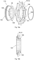
- FIG. 2a-b 12 show the multi-pinion assembly 10, which includes the multi-pinion assembly 12 and the plug assembly 14.
- the multi-pinion assembly 10 is connected to a driver 16 and forms with it the rear wheel assembly 3.
- the rear wheel assembly 3 is arranged on a rear wheel hub 11, which runs between the two opposite frame sections 1, 2 and by means of a rear wheel axle 19 on the frame sections 1, 2 is attached or attachable.
- a derailleur hanger 22 is arranged between the frame section 1 and the rear wheel assembly 3 and is used for mounting the rear derailleur 4 and through which the rear wheel hub 11 runs.
- the multiple sprocket assembly 12 is shown as having twelve sprockets R1-R12.
- Figure 2a shows a multi-pinion arrangement 12 in which the four largest pinions R1-R4 are connected to a spider 13 so that the torque is transmitted via the spider 13 to the driver 16.
- the four largest sprockets are spaced radially from the driver 16 .
- the six middle pinions R4-R9 are each spaced apart axially by spacers 17 and engage directly in the driver 16 in a torque-transmitting manner.
- the two smallest sprockets R11, R12 are connected in a torque-transmitting manner to the locking screw arrangement 14 via the third smallest sprocket R10.
- Figure 2b 12 shows an alternative multi-sprocket arrangement 12 in which the sprockets are connected to one another with pins/bolts 19.
- FIG. Only the largest pinion R1 is connected to the driver 16 in a torque-transmitting manner, ie it extends radially to the driver 16.
- the other pinions R2-R12 are spaced radially from the driver 16.
- the three smallest sprockets are designed in one piece, for example welded, and are connected to the driver 16 in a torque-transmitting manner via the third smallest sprocket R10 and are axially fixed via the locking screw arrangement 14 .
- FIG. 2a-b show Figures 2a-b the installation width D0 available for the components to be attached to the rear wheel hub 11, which is at least 142 mm.
- the installation width is the distance from an outside of a left hub end cap 23 adjacent to frame section 2 to an outside of the right hub end cap 25 adjacent to frame section 1.
- the third smallest pinion R10 is arranged on an outer peripheral surface 24 of the driver 16 and is radially supported on the driver 16 .
- the third-smallest pinion R10 engages in a driver profile 26 arranged on the outer circumferential surface 24 of the driver 16, as a result of which the third-smallest pinion R10 is coupled to the driver 16 in a rotationally fixed manner.
- the two smallest sprockets R11, R12 are located at least partially axially outside of the driver 16 and adjacent to the third smallest sprocket R10.
- An enlarged view of the three smallest sprockets R10-R12 mounted on the driver 16 and axially fixed by the locking screw assembly 14 is shown in FIG figure 3 shown.
- Axial directions used in this application relate to the bicycle center plane 30 and the frame sections 1, 2, as in Figure 4a evident.
- An axially inward direction A i is defined as the direction from one of the frame sections 1, 2 towards the bicycle center plane 30, whereas an axially outward direction A a is defined as the direction from the bicycle center plane towards the frame section 1.
- the axial directions R i and R a are consequently opposite to each other. If, on the other hand, one speaks of a direction radially outwards R a , then this is a direction that runs orthogonally to an axis of rotation 32 of the multiple pinion arrangement 12 and points away from it.
- a radially inward direction R i is opposite to the radially outward direction R a and is a direction toward the axis of rotation 32 of the multiple sprocket assembly 12 .
- the axis of rotation 32 of the multi-pinion arrangement 3 runs parallel to the rear wheel hub and falls with it a rotational or longitudinal axis of the rear wheel hub together. The directions mentioned are in figure 3 shown.
- FIG. 4a The rear wheel assembly 3 shown on the frame section 1 is shown in FIG Figure 4a as rear view and in Figure 4b shown as a side view. As best in Figure 4b As can be seen, the rear wheel assembly 3 is attached to a frame dropout 8 of the frame section 1 of the bicycle frame.
- the driver 16 On its axially outer side in the installed state, the driver 16 has an opening in which an internal thread 34 is arranged.
- the locking screw arrangement 14 can engage in the internal thread 34 .
- FIG. 5 A detailed view of the locking screw arrangement 14 according to an embodiment of the invention with at least two smallest pinions R11, R12 accommodated thereon is in figure 5 shown.
- the at least two smallest sprockets R11, R12 are accommodated on a shank section 36.
- the shank section 36 is provided with an axially outer stop section 38 at its one end area.
- An external thread 40 assigned to the shank section is arranged on the opposite end region of the shank section 36 .
- the external thread 40 of the locking screw arrangement can engage in the internal thread 34 of the driver 16 .
- the external thread 40 then serves as a diameter-mediating ring element between the driver 16 and the shank section 36.
- the rear wheel assembly 3 When the rear wheel assembly 3 is assembled, it is therefore arranged axially inside the internal thread 34 of the driver 16 and adjacent to the shank section 36 of the locking screw arrangement 14.
- the outside diameter d1 of the stop section 38 and the outside diameter d2 of the external thread 40 are larger than an outside diameter d3 of the shank section 36 in that area which is intended to accommodate the at least one of the at least two smallest sprockets R11, R12. This results in a locking screw arrangement 14 with an undercut.
- the outer diameter d2 of the external thread 40 assigned to the shank section can be between 30.1 mm and 30.6 mm, preferably 30.5 +/- 0.2 mm.
- the outer diameter d3 of the shaft section 36 in that area in which the at least one of the at least two smallest sprockets R11, R12 is accommodated can be between 26.0 mm and 27.5 mm, preferably 26.8 +/- 0.2 mm or alternatively be about 24mm.
- the shank section can include a step, so that it has a respective area with the specified alternative inner diameters.
- the undercut between an inner side surface 42 of the external thread 40 assigned to the shank section and an inner side surface 44 of the stop section 38 has an axial length L1 between 3.2 mm and 5.0 mm.
- An axial length L2 of the locking screw arrangement 14 is, for example, between 7.5 mm and 10.3 mm, preferably 9.0 +/- 0.2 mm.
- an axial length L3 of the external thread 40 associated with the shank portion can be between 2.5 mm and 3.5 mm, preferably 3.0 +/- 0.2 be mm.
- the shaft section 36 accommodates the two smallest sprockets R11, R12 of the multiple sprocket arrangement 12.
- the at least two smallest pinions R11, R12 are designed to be radially self-supporting, so there is a distance in the radial direction between the shaft section 36 and the two smallest pinions R11, R12.
- the radially self-supporting design of the at least two smallest pinions R11, R12 is achieved in that they are connected to one another and to an adjacent, larger pinion R10, for example by means of a joining process or by a latching mechanism.
- the smallest sprocket R10 coupled to the driver and the adjacent next smaller sprocket R11 received on the locking screw assembly each have a collar with teeth and indentations that can engage and set a desired angular position of the sprockets relative to one another.
- the smallest sprocket R12 bears against the stop section 38 with an axially outer region, so that when the rear wheel assembly 3 is in the mounted state, the multiple sprocket arrangement 12 is axially fixed.
- the smallest pinion R12 has a recess 41 radially inward and axially outward, into which the stop section 38 engages.
- the engagement can be such, for example, that the stop section 38 is at least partially accommodated in the recess 41, as in FIG figure 5 shown.
- an outside surface 46 of the smallest sprocket R12 may coincide with a face 48 of the stop portion 38 .
- the screw plug arrangement 14 is screwed with its external thread 40 into the internal thread 34 of the driver 16 .
- the rotational force required for this can be transferred to the locking screw arrangement 14 with the aid of a tool.
- the locking screw arrangement 14 has a tool interface 50 on an inner peripheral surface, into which the tool can engage in a torque-transmitting manner.
- the inner peripheral surface of the plug assembly 14 can define an inner diameter d4 of the shank portion 36 that is between 23.8 mm and 25.0 mm, preferably 24.0 +/- 0.2 mm.
- the inner diameter d5 of the smallest sprocket R12 received on the plug screw assembly 14 is larger than the outer diameter d3 of the shank portion 36, so that the plug screw assembly 14 can rotate relative to the sprockets received thereon.
- the latter is provided with joints. Possible joints 52, 54, 56 of the locking screw arrangement 14 are in figure 6 shown. These are located between the shank section 36 and the axially outer stop section 38, in the area between the shank section 56 and the associated external thread 40 and/or in the area of the shank section 36.
- the locking screw arrangement 14 has at least one of these joints 52, 54, 56.
- the pinions R10, R11, R12 can be connected to one another by means of joints 58.
- Figures 7a-e show possible joints 58 between the three smallest sprockets R10, R11, R12.
- the joints 58 are located adjacent to a connecting portion 60 which is arranged between two adjacent sprockets and defines their distance from one another.
- the smallest pinion R12 is attached to a connecting portion 60 between the smallest and the second smallest pinion R12, R11, see Figure 7a .
- the second smallest pinion R11 can be integrally formed with two opposing connecting portions 60 and the smallest pinion R12 can be attached to one of the connecting portions 60, see Figure 7c .
- the smallest sprocket R12 may be integrally formed with a connecting portion 60 and the second smallest sprocket R11 may be attached to the connecting portion 60 of the smallest sprocket R12, see Figure 7d .
- the joint 58 can run parallel or orthogonal to the axis of rotation 32 of the multi-pinion arrangement 12 .
- the joint 58 can have an axial offset.
- Figures 8a-c each show the recorded on the screw plug assembly 14 smallest sprocket R12 in engagement with a bicycle chain 5.
- the bicycle chain 5 is driven via a front chain ring, not shown, and can have a
- the torque transmitted to the smallest sprocket R12 by the bicycle chain 5 is transmitted from the smallest sprocket R12 to at least one larger sprocket R10 which is connected to the driver 16 in a torque-transmitting manner.
- the connecting sections 60, 64 arranged between the pinions also contribute to the torque transmission between the pinions R10, R11, R12.
- latching mechanisms such as meshing teeth and indentations, can be provided for torque transmission.
- Figures 9a-c show an alternative embodiment of the locking screw arrangement 14, in which the axially outer stop section 38 is formed by a plurality of snap hooks 66.
- the snap hooks 66 are distributed over the outer circumference of the locking screw arrangement 14 and are spaced apart from one another. This embodiment enables the locking screw arrangement 14 to be formed integrally. Joints can therefore be dispensed with.
- the snap hooks 66 and, if applicable, the shank section 36 have such an elasticity that the locking screw arrangement 14 can be pushed past the in Figure 9a marked direction 68 can be pushed into the pinion to be accommodated until the recess 41 of the smallest pinion R12 comes into engagement with the snap hook 66, as in Figure 9c shown.
- the recess 41 is enlarged by a radially inwardly projecting projection 69 on the smallest pinion R12.
- Figures 10a-b show an alternative embodiment of the locking screw arrangement 14, in which the axially outer stop section 38 is formed by a securing element 68, for example as a ring element.
- the securing element 68 engages both in the recess 41 of the smallest sprocket R12 and in a groove 70 formed in the end region of the shaft section 36 .
- the securing element 68 represents an axial fixation of the pinions accommodated on the shaft section.
- the locking screw arrangement is pushed into the pinions R12, R11 to be accommodated in the direction of arrow 72 until these are arranged in the area of the shaft section .
- the securing element 68 is then brought into engagement with the recess 41 and the groove 70 .
- Figures 11a-b and 12a-b 14 each shows a sectional view of the rear wheel assembly 3 in a state where the multi-pinion assembly 10 and the driver 16 are placed against each other but not coupled with each other.
- two smallest pinions R11, R12 are interconnected and rotatable relative to the locking screw assembly.
- a desired angular positioning of the pinions R11 , R12 accommodated on the shaft section relative to a further pinion R10 which is coupled in a torque-proof manner to the driver 16 , can take place during or after the locking screw arrangement 14 is screwed into the driver 16 .
- the pinions R12 , R11 accommodated on the shaft section are designed to be radially self-supporting, ie are not radially supported on it, and can rotate relative to the locking screw arrangement 14 .
- the two smallest sprockets R12, R11 can be fixed radially by means of a latching mechanism, for example a latching structure with teeth and indentations is provided between the second smallest and the third smallest sprocket.
- a joining method other than latching can be selected for the connection.
- the above embodiment is optimized in terms of manufacturing cost of the multi-pinion assembly.
- the two smallest sprockets R12, R11 accommodated on the shaft section are connected to the third smallest sprocket R10. That is to say, the angular positions of the three smallest sprockets relative to one another are already fixed before the locking screw arrangement 14 is screwed into the driver 16 .
- the angular position of the three smallest sprockets can be adjusted in such a way that the third smallest sprocket R10 can engage in the driver profile 26 of the driver 16, whereby the desired angular position of the three smallest sprockets in relation to further sprockets of the Multiple sprocket assembly 12 is fixed.
- the above embodiment offers a simple assembly of the sprockets of the multi-sprocket arrangement to be attached via the screw plug arrangement.
- the locking screw arrangement 14 is designed in two parts and comprises a first and a second component 74 , 76 .
- the two components 74, 76 can be separated from one another.
- the two in Figures 13a-d and 14a-d The components 74, 76 shown are connected to one another by means of connecting threads 78, 79 which engage in one another and which are arranged in the region of the shaft section 36.
- the external thread 40 assigned to the shank section is arranged on the first component 74 and the axially outer stop section 38 is arranged on the second component 76 .
- the two components 74, 76 have a respective tool interface 80, 82 which enables the same tool 83 to engage.
- the tool interfaces 80, 82 are radial arranged inside on an inner peripheral surface of the first or second component.
- figure 15 shows the two-piece locking screw arrangement 14 with its two components 74, 76 on a common axis.
- the tool 83 selectively engages in one of the two components 74, 76, see FIG Figure 16a-b , or both components 74, 76, see figure 17 , a.
- the first component 74 can first be screwed into the driver 16 and the second component 76 can then be screwed into the first component 74 .
- the first component 74 acts as a diameter-mediating ring element.
- the two components 74, 76 can first be connected to one another before they are screwed into the driver 16.
- the at least one smallest pinion R12, R11 to be accommodated is accommodated in the region of the shaft section 36 of one of the two components 74, 76.
- the two components 74, 76 can first be screwed together as far as they will go.
- One of the components 74, 76 can then be rotated back until the tool interfaces 80, 82 of the two components 74, 76 are aligned with one another.
- the turning back should account for a small axial offset, with 12 engagement points the angle is about 29°, for example.
- the multiple pinion assembly 10 is coupled or capable of being coupled to a driver 16 .
- the driver 16 which is also referred to as the "standard driver” in professional circles due to its widespread use, is in Figures 18a-c shown as a separate component with selected characteristic dimensions marked.
- the driver profile 26 includes driver projections or so-called splines 84. At least one of the splines 84 differs in its dimensions from the other splines of the driver profile 26.
- pinions to be fastened to the driver 16 have an inner contour that corresponds to the driver profile 26 of the driver 16 are designed to be complementary.
- the pinion with a corresponding inner contour and the driver 16 can engage in a torque-transmitting manner.
- the number of splines is greater than or equal to 8, preferably greater than or equal to 9.
- the number of splines can also be less than or equal to 22.
- the driver 16 has the driver profile 26 on a first region of its radial outer surface, which extends along a first axial length LA1 from a driver stop 86 in an axially outward direction A a .
- a driver stop 86 is generally referred to as a section of the driver 16 against which the multiple pinion arrangement 12 attached thereto strikes and by means of which the position of the multiple pinion arrangement 12 relative to the driver 16 can be fixed.
- This first axial length LA1 of the driver 16 is preferably greater than 32.9 mm, preferably 33.2 +/-0.4 mm.
- An outer diameter dA1 in this first area, measured on the radial outer surfaces of the driver profile 26, is greater than 34.2 mm, for example, preferably 34.5+/-0.15 mm.
- the first area with the driver profile 26 is followed by a relatively short second area in which the radial outer surface of the driver 16 is free of the driver profile and is therefore smooth.
- a second axial length LA2 of the driver 16 extends from the driver stop 86 to an axially outer face 88 of the driver 16 and is between 33.9 mm and 35.9 mm, but preferably 34.9 +/- 0.3 mm.
- An outer diameter dA2 of the second area can be greater than 31.4 mm and is preferably 32.1+0.4/-0.2 mm.
- the driver 16 has the internal thread 34 pointing radially inwards adjacent to its axially outer end face 88 .
- the internal thread 34 preferably has a nominal diameter dA3 greater than 29.8 mm and preferably approximately 30.6 mm.
- a preferred pitch of the internal thread of the driver is 24 TPI, so that the thread can also be characterized as M 30.6 x 24 TPI based on known dimensions.
- a first axial distance D1 from the driver stop 86 to the outside surface 46 of the smallest sprocket R12 is greater than 38 mm, for example greater than 39.1 mm, and more preferably 39.9 +/- 0.2 mm .
- a second axial distance D2 from the axially outer face 88 of the driver 16 to the outboard side surface 46 of the smallest sprocket R12 is greater than 4.0 mm and is preferably 5.0 +/- 0.2 mm.
- a third distance D3 in the axial direction from the outside surface 46 of the smallest sprocket R12 to a peripheral surface 90 of the frame section 1 or the rear dropout 8 is less than 8.2 mm and preferably 7.2 +/- 0.2 mm.
- the frame section 1 or its dropout 8 has a recessed surface 92 which serves to accommodate the derailleur hanger 22 .
- a fourth axial distance D4 from the outside surface 46 of the smallest sprocket R12 to the recessed surface 92 may be less than 12.2 mm and is preferably 11.2 +/- 0.2 mm.
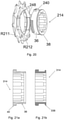
- the following in the figures 19 and 20 shown versions relate to a segmented screw plug.
- the segments are located at one or both axial ends 138, 240 of the outer peripheral surface of the plug assembly.
- the segments of the locking screw include sections with alternately larger and smaller outer diameters and are matched to a likewise segmented inner peripheral surface of the smallest sprocket.
- the segments on the inner peripheral surface on the smallest sprocket also include sections of alternating smaller and larger inner diameter.
- the segmented locking screw and the segmented pinion can be mechanically connected and separated again by plugging them into each other and twisting them - principle of a bayonet lock.
- the figures 19 a and b show views of the first embodiment of the segmented screw plug 114 .
- the segments on stop portion 138 include portions with a larger outside diameter d1 and a smaller outside diameter d3.
- the outside diameter d1 of the sections with the larger outside diameter is larger than the outside diameter d3 of the shank section 36.
- the outside diameter d3 of the sections with the smaller outside diameter corresponds to the outside diameter d3 of the shank section 36.
- the thread 140 has an outside diameter d2 that is larger than the outside diameter d3 of the Shank portion 36 is.
- the smallest sprocket R112 has a segmented inner peripheral surface with recesses 148 .
- the segments 138 of the locking screw 114 are matched to the segments 148 of the smallest sprocket R112.
- the smallest pinion R112 has an inner diameter d5 and three recesses 148 distributed along the inner circumference.
- An imaginary diameter along the recesses 148 is larger than the inside diameter d5 of the smallest sprocket R112 and also larger than the outside diameter d1 of the segments 138 of the locking screw 114.
- the two smallest sprockets are oriented to the locking screw 114 in such a way that the segments 138 of the locking screw 114 Recesses 148 on the inner circumference of the smallest pinion R112 can happen.
- the pinions R11 and R112 are pushed onto the locking screw 114 and positioned in the shaft section 36, the pinions are rotated relative to the screw 114, so that the larger-diameter segments 138 of the locking screw 114 engage behind the smallest pinion R112 and secure it axially - see in particular Figure 19b .
- the inner diameter d5 of the smallest sprockets R11, R112 accommodated on the locking screw assembly 114 is larger than the outer diameter d3 of the shank portion 36, so that the locking screw assembly 114 can rotate relative to the gears.
- the pinions are designed to be self-supporting.
- a securing element 168 can secure the pinions R11 and R112 on the locking screw 114 in the axial direction.
- the securing element 168 is arranged in the axial direction between the smallest pinion R112 and the segmented stop section 138 .
- the securing element 168 can be designed as a snap ring.
- the smallest sprocket R112 may have a groove 141 for receiving the snap ring 168 .
- the smallest sprockets R11 and R112 are fixed in the axial direction between the larger-diameter thread 140 and the larger-diameter segments 138 together with the snap ring 168 .
- figure 20 12 shows an alternative embodiment of the segmented screw plug 214.
- the outer peripheral surface of the screw plug 214 has a segmented threaded section 240.
- FIG. The locking screw 214 includes a stop portion 38, a shank portion 36 and a segmented thread 240.
- the functional principle follows the previous embodiment.
- the external thread 240 is formed in segments and alternately comprises three larger-diameter threaded sections and three smaller-diameter sections without a thread.
- the threaded sections 240 have an outside diameter d2, which is larger than the outside diameter d3 of the shank section 36.
- the stop section 38 also has an outside diameter d1, which is larger than the shank section 36--compare the explanations at figure 5 .
- the smallest sprocket R212 has a segmented inner peripheral surface with recesses 248 .
- the segments 240 of the locking screw 214 are matched to the segments 248 of the smallest sprocket R212.
- the smallest pinion R212 has an inner diameter d5 and three recesses 248 distributed along the inner circumference.
- An imaginary inner diameter along the recesses 248 is larger than the inner diameter d5 of the smallest sprocket R212 and also larger than the outer diameter d1 of the stop section 38 of the locking screw 214.
- the two smallest sprockets R211, R212 are oriented to the locking screw 214 such that the segments 240 of the locking screw 214 can pass the recesses 248 on the inner circumference of the smallest sprocket R112.
- the pinions R211 and R212 are pushed onto the locking screw 214 and positioned in the shaft section 36, the pinions are rotated relative to the screw 214, so that the larger-diameter thread segments 240 of the locking screw 214 engage behind the smallest pinion R212 and secure it axially - cf. in particular Figure 19b .
- the advantage of this design is that neither an additional component (such as the snap ring) nor a joining technique is required.
- the locking screw arrangement 214 As soon as the smallest sprockets are mounted on the locking screw arrangement 214, they can no longer be pulled off axially outwards due to the axial stop section 38. If, in a next step, the locking screw arrangement 214 with the pinions R211, R212 is screwed to the internal thread 34 of the driver via the thread segments 240, the pinions are also fixed axially inwards.
- the screw plug is initially produced in one piece or integrally and, in a further processing step, the outside diameter is increased by forming at one or both axial ends.
- This allows cost-effective production without additional components or joining processes.
- the outer diameter of the axial stop section and/or the threaded section can be reduced by forming, e.g. B. be increased by flanging.
- Figure 21a shows a sectional view of the one-piece screw plug 314 with the thread 40, the shank portion 36 and the adjoining, not yet formed, axial end.
- the axial end and the shank section 36 have the same outer diameter d3.
- Figure 21b shows the reshaped stop section 338 with the increased outer diameter d1.
- the outer diameter d1 of the axially outer stop section 338 is enlarged relative to the outer diameter d3 of the shaft section 36 as a result of the reshaping.
- the larger-diameter threaded section 40 could also be produced by forming. Further processing steps such as thread (re)cutting can follow.
- the above exemplary embodiments relate to a multi-sprocket arrangement with 12 sprockets, the invention can equally apply to a multi-sprocket arrangement with other numbers of sprockets, such as 11 or 13 sprockets.
Abstract
Eine Mehrfachritzel-Baugruppe (10) für eine Hinterradbaugruppe (3) für ein Fahrrad mit Kettenschaltung umfasst eine Mehrfachritzelanordnung (12) und eine Verschlussschraubenanordnung (14). Die Mehrfachritzelanordnung (12) ist zur drehmomentübertragenden Kopplung mit einem Antreiber (16) der Hinterradbaugruppe (3) ausgebildet und umfasst wenigstens 11 Ritzel mit sich unterscheidenden Zähnezahlen. Die Mehrfachritzel-Baugruppe (10) ist derart ausgebildet, dass im montierten Zustand wenigstens zwei der kleinsten Ritzel (R11, R12) über die Verschlussschraubenanordnung (14) an dem Antreiber (16) axial fixiert sind. Die Verschlussschraubenanordnung (14) weist einen Schaftabschnitt (36) zur Aufnahme wenigstens eines der wenigstens zwei kleinsten Ritzel (R11, R12) auf, wobei der Schaftabschnitt (36) an seinem einen Endbereich mit einem axial außenliegenden Anschlagabschnitt (38) versehen ist und wobei dem Schaftabschnitt (36) an seinem entgegengesetzten Endbereich wenigstens ein Außengewinde (40) zugeordnet ist, mit dem die Verschlussschraubenanordnung (14) in ein zugeordnetes Innengewinde (34) zum Fixieren der Verschlussschraubenanordnung (14) einschraubbar ist. Das dem Schaftabschnitt zugeordnete Außengewinde (40) weist einen Außendurchmesser (d2) auf, der größer ist als ein Außendurchmesser (d3) des Schaftabschnitts (36) in demjenigen Bereich, in dem das wenigstens eine der wenigstens zwei kleinsten Ritzel (R11, R12) aufgenommen ist.A multiple sprocket assembly (10) for a rear wheel assembly (3) for a derailleur bicycle includes a multiple sprocket assembly (12) and a locking screw assembly (14). The multiple pinion arrangement (12) is designed for torque-transmitting coupling with a driver (16) of the rear wheel assembly (3) and comprises at least 11 pinions with different numbers of teeth. The multiple pinion assembly (10) is designed in such a way that in the assembled state at least two of the smallest pinions (R11, R12) are fixed axially to the driver (16) via the locking screw arrangement (14). The locking screw arrangement (14) has a shank section (36) for receiving at least one of the at least two smallest sprockets (R11, R12), the shank section (36) being provided at one end area with an axially outer stop section (38) and the At least one external thread (40) is assigned to the shank section (36) on its opposite end region, with which the screw plug arrangement (14) can be screwed into an associated internal thread (34) for fixing the screw plug arrangement (14). The external thread (40) associated with the shank section has an outside diameter (d2) that is larger than an outside diameter (d3) of the shank section (36) in the area in which the at least one of the at least two smallest sprockets (R11, R12) is accommodated is.
Description
Die vorliegende Erfindung betrifft eine Mehrfachritzel-Baugruppe für ein Fahrrad mit Kettenschaltung, die eine Mehrfachritzelanordnung sowie eine Verschlussschraubenanordnung umfasst. Ferner betrifft die Erfindung eine Hinterradbaugruppe für ein Fahrrad mit Kettenschaltung mit einer Mehrfachritzel-Baugruppe.The present invention relates to a multi-sprocket assembly for a derailleur bicycle that includes a multi-sprocket assembly and a plug assembly. The invention also relates to a rear wheel assembly for a derailleur bicycle having a multi-sprocket assembly.
Eine Hinterradanordnung für ein Fahrrad mit Kettenschaltung umfasst typischerweise eine Mehrfachritzelanordnung, die mit der Hinterradnabe über einen Antreiber gekoppelt oder koppelbar ist. Ritzel der Mehrfachritzelanordnung sind mit dem Antreiber drehmomentübertragend verbunden. Zur Fixierung der Ritzel gegen eine axiale Verschiebung wird herkömmlicherweise ein Verschlussring verwendet. Ein solcher Verschlussring weist an einem Endbereich ein Außengewinde und an einem entgegengesetzten Endbereich eine sich radial erstreckende Auskragung auf. Im montierten Zustand der Hinterradbaugruppe greift das Außengewinde des Verschlussrings in ein Innengewinde des Antreibers ein, sodass die Auskragung an einer Außenseitenfläche des kleinsten Ritzels anliegt. Auf diese Weise fixiert der Verschlussring die Ritzel der Mehrfachritzelanordnung gegen eine axiale Verschiebung.A rear wheel assembly for a derailleur bicycle typically includes a multiple sprocket assembly coupled or coupleable to the rear wheel hub via a driver. Pinions of the multiple pinion assembly are torque-transmittingly connected to the driver. A locking ring is conventionally used to fix the pinions against axial displacement. Such a locking ring has an external thread on one end area and a radially extending projection on an opposite end area. When the rear wheel assembly is assembled, the male thread of the lock ring engages a female thread of the driver so that the overhang abuts an outside surface of the smallest sprocket. In this way, the locking ring fixes the sprockets of the multiple sprocket assembly against axial displacement.
Der Antreiber steht über eine Freilaufkupplung mit der Hinterradnabe in drehmomentübertragendem Eingriff und lässt eine Drehmomentübertragung in der einen Drehrichtung (Antriebsrichtung) zu, wohingegen der Antreiber in der anderen Richtung von der Hinterradnabe über eine Freilaufmechanik drehentkoppelt ist. Die Hinterradnabe ist im montierten Zustand mit einer Hinterradachse verbunden, die an ihren entgegengesetzten Enden an einem jeweiligen Ausfallende eines Fahrradrahmens angebracht ist. Der Fahrradrahmen legt somit zwischen seinen beiden Ausfallenden und deren Innenabstand zueinander eine Einbaubreite für alle an der Hinterradnabe zu befestigenden Komponenten fest, wie ein Laufrad, einen Antreiber, eine Mehrfachritzelanordnung, eine Nabenendkappe und ggf. weiterer Komponenten beispielsweise zur Anbringung eines hinteren Kettenumwerfers.The driver is in torque-transmitting engagement with the rear wheel hub via a one-way clutch and allows torque transmission in one direction of rotation (drive direction), while the driver is rotationally decoupled from the rear wheel hub in the other direction by a free-wheel mechanism. When assembled, the rear wheel hub is connected to a rear wheel axle which is attached at its opposite ends to a respective dropout of a bicycle frame. The bicycle frame thus defines an installation width between its two dropouts and their inner distance to each other for all components to be attached to the rear wheel hub, such as a wheel, a driver, a multiple sprocket arrangement, a hub end cap and possibly other components, for example for attaching a rear derailleur.
In den vergangenen Jahren haben sich Kettenschaltungen mehr und mehr durchgesetzt, bei denen im Bereich der Tretkurbel lediglich ein einziges Kettenrad vorgesehen ist. Diese Entwicklung geht einher mit der stärkeren Verbreitung von motorisch unterstützten Fahrrädern. Sie wurde aber angestoßen durch die Idee, eine gewichtsintensive Anordnung mehrerer Kettenräder mit einem zugeordneten vorderen Umwerfer zu eliminieren. Durch diese Entwicklung wurde es erforderlich, eine größere Übersetzungsspreizung über die Bereitstellung hinreichend vieler Gänge an der hinteren Mehrfachritzelanordnung (Kassette) bereitzustellen. Aufgrund der begrenzten und meist standardisierten Einbaubreite, die für alle an der Hinterradnabe zu befestigenden Komponenten zur Verfügung steht, und der vorgegebenen Breite handelsüblicher Ketten kann aber der steigende Bedarf nach mehr Gängen und folglich mehr Ritzeln nicht einfach dadurch gelöst werden, dass beliebig viele Ritzel der Mehrfachritzelanordnung hinzugefügt werden. Der zur Verfügung stehende Bauraum (Einbaubreite) steht der Breite üblicher Ketten und der entsprechenden Breite der einzelnen Ritzel als limitierender Faktor gegenüber. Um mit einer begrenzten Ritzelanzahl dennoch ein verbessertes Übersetzungsverhältnis zu erzielen, besteht ein Bestreben darin, den Übersetzungsbereich zwischen dem größten und dem kleinsten Ritzel zu vergrößern. Besonders wichtig ist dabei für den Benutzer im professionellen Radsport oder auch im Freizeitsport sowohl einen möglichst kleinen (größtes Ritzel) als auch einen möglichst großen Gang (kleinstes Ritzel) zur Verfügung zu haben, um einerseits steile Anstiege komfortabel fahren zu können und andererseits bei gleicher Trittfrequenz eine hohe Geschwindigkeit zu erzielen. Die dazwischenliegenden Ritzel der Mehrfachritzelanordnung müssen entsprechend aufeinander abgestimmt sein. Große Übersetzungssprünge zwischen benachbarten Ritzeln sind möglich, sollten aber in der Regel vermieden werden.In recent years, derailleur gears have become more and more popular, in which only a single sprocket is provided in the area of the pedal crank. This development goes hand in hand with the increasing spread of motorized bicycles. But it was triggered by the idea of a weight-intensive arrangement of several sprockets with an associated front derailleur to eliminate. This development made it necessary to provide a larger spread of translations by providing a sufficient number of gears on the rear multi-sprocket arrangement (cassette). Due to the limited and mostly standardized installation width that is available for all components to be attached to the rear wheel hub, and the specified width of commercially available chains, the increasing need for more gears and consequently more sprockets cannot simply be solved by simply using any number of sprockets of the Multiple sprocket arrangement to be added. The available installation space (installation width) is the limiting factor compared to the width of conventional chains and the corresponding width of the individual sprockets. In order to nevertheless achieve an improved transmission ratio with a limited number of sprockets, there is an effort to increase the transmission range between the largest and the smallest sprocket. It is particularly important for the user in professional cycling or in leisure sports to have both the smallest possible (largest sprocket) and the largest possible gear (smallest sprocket) available in order to be able to ride steep climbs comfortably on the one hand and with the same cadence on the other to achieve high speed. The intermediate sprockets of the multiple sprocket arrangement must be matched to one another accordingly. Large gear ratio jumps between adjacent sprockets are possible, but should generally be avoided.
Für das Bestreben, kleine Ritzel für einen möglichst großen Gang bereitzustellen, setzt die Geometrie des Antreibers bei herkömmlichen Lösungen Grenzen. Herkömmlicherweise sind die Ritzel am radialen Außenumfang des Antreibers befestigt, wodurch ein minimaler Innendurchmesser (Fußkreis) der Ritzel durch den Außendurchmesser des Antreibers bereits vorgegeben ist. Bei der Verwendung von auf dem Markt verbreiteten Antreibern lässt sich aufgrund der Geometrie des Antreibers gerade noch ein kleinstes Ritzel mit 11 Zähnen an der Ritzelanordnung anbringen und durch den Verschlussring gegen eine axiale Verschiebung fixieren.When trying to provide small sprockets for the largest possible gear, the geometry of the driver sets limits with conventional solutions. Conventionally, the pinions are attached to the radial outer circumference of the driver, as a result of which a minimum inner diameter (root circle) of the pinions is already predetermined by the outer diameter of the driver. When using drivers that are widely available on the market, due to the geometry of the driver, the smallest sprocket with 11 teeth can just be attached to the sprocket assembly and fixed against axial displacement by the locking ring.
Dennoch besteht ein Bedarf im Radsport an sehr kleinen Ritzeln, d.h. Ritzeln mit 10 oder weniger Zähnen. Um diesem Bedarf gerecht zu werden, gibt es im Stand der Technik Ansätze, einen neuen, sich von dem Standardantreiber unterscheidenden Antreiber zu verwenden, der durch geeignete konstruktive Maßnahmen die Anbringung eines Ritzels mit einer Zähnezahl kleiner als 11 zulässt. Derartige Sonderlösungen sind jedoch im Vergleich zu Standardlösungen kostenintensiver aufgrund der geringeren Fertigungszahlen und zudem meist nicht kompatibel mit bereits herkömmlichen Bauteilen einer Hinterradbaugruppe und den handelsüblich verfügbaren Antreibern. Derartige Sonderlösungen lassen sich darüber hinaus im Markt schwer platzieren.However, there is a need in cycling for very small sprockets, ie, sprockets with 10 teeth or fewer. In order to meet this need, there are approaches in the prior art to use a new driver that differs from the standard driver, which allows the attachment of a pinion with a number of teeth less than 11 through suitable design measures. However, such special solutions are more expensive than standard solutions due to the lower production numbers and are also usually not compatible with already conventional components of a rear wheel assembly and those that are commercially available drivers. Such special solutions are also difficult to place on the market.
Aus dem Dokument
Eine weitere Möglichkeit zur Verwendung von zwei Ritzeln mit einem Innendurchmesser, der kleiner ist als ein Außendurchmesser des Antreibers, ist in der Offenlegungsschrift
Der Erfindung liegt die Aufgabe zugrunde, eine Mehrfachritzel-Baugruppe und eine Hinterradbaugruppe bereitzustellen, die auf einfache Weise ein verbessertes Übersetzungsverhältnis bereitstellt und sich auch mit einem herkömmlichen Antreiber-Typ koppeln lässt.It is an object of the invention to provide a multiple sprocket assembly and rear wheel assembly that easily provides an improved gear ratio and can also be coupled with a conventional driver type.
Diese Aufgabe wird durch eine Mehrfachritzel-Baugruppe für ein Fahrrad mit Kettenschaltung mit den Merkmalen des Anspruchs 1 gelöst. Ferner wird diese Aufgabe durch eine Hinterradbaugruppe für ein Fahrrad mit Kettenschaltung mit den Merkmalen des Anspruchs 16 gelöst.This object is achieved by a multiple sprocket assembly for a bicycle with derailleur gears having the features of
Weitere Ausführungsformen der Erfindung sind in den abhängigen Patentansprüchen angegeben.Further embodiments of the invention are specified in the dependent claims.
Gemäß einem ersten Aspekt der Erfindung umfasst eine Mehrfachritzel-Baugruppe für eine Hinterradbaugruppe für ein Fahrrad mit Kettenschaltung eine Mehrfachritzelanordnung und eine Verschlussschraubenanordnung. Die Mehrfachritzelanordnung ist zur drehmomentübertragenden Kopplung mit einem Antreiber der Hinterradbaugruppe ausgebildet und umfasst wenigstens 11 Ritzel mit sich unterscheidenden Zähnezahlen. Die Mehrfachritzel-Baugruppe ist derart ausgebildet, dass im montierten Zustand des Antreibers mit der Mehrfachritzel-Baugruppe wenigstens zwei der kleinsten Ritzel über die Verschlussschraubenanordnung an dem Antreiber axial fixiert sind. Die Verschlussschraubenanordnung weist einen Schaftabschnitt zur Aufnahme wenigstens eines der wenigstens zwei kleinsten Ritzel auf. Der Schaftabschnitt ist an seinem einen Endbereich mit einem axial außenliegenden Anschlagabschnitt versehen. Ferner ist dem Schaftabschnitt an seinem entgegengesetzten Endbereich wenigstens ein Außengewinde zugeordnet, mit dem die Verschlussschraubenanordnung in ein zugeordnetes Innengewinde zum Fixieren der Verschlussschraubenanordnung einschraubbar ist. Die erfindungsgemäße Lösung sieht vor, dass das dem Schaftabschnitt zugeordnete Außengewinde einen Außendurchmesser aufweist, der größer ist als der Außendurchmesser des Schaftabschnitts in demjenigen Bereich, in dem das wenigstens eine der wenigstens zwei kleinsten Ritzel aufgenommen ist.According to a first aspect of the invention, a multi-sprocket assembly for a rear wheel assembly for a derailleur bicycle includes a multi-sprocket assembly and a plug assembly. The multiple sprocket assembly is configured for torque-transmitting coupling to a driver of the rear wheel assembly and includes at least 11 sprockets with differing numbers of teeth. The multiple pinion subassembly is designed in such a way that when the driver is assembled with the multiple pinion subassembly, at least two of the smallest pinions are fixed axially to the driver via the locking screw arrangement. The locking screw arrangement has a shank section for receiving at least one of the at least two smallest sprockets. The shank section is provided at its one end area with an axially outer stop section. Furthermore, at least one external thread is associated with the shaft section on its opposite end region, with which the screw plug arrangement can be screwed into an associated internal thread for fixing the screw plug arrangement. The solution according to the invention provides that the external thread assigned to the shank section has an outside diameter that is larger than the outside diameter of the shank section in that area in which at least one of the at least two smallest sprockets is accommodated.
Die erfindungsgemäße Lösung sieht vor, dass wenigstens zwei der kleinsten Ritzel, d. h. wenigstens zwei der Ritzel mit den kleinsten Zähnezahlen, an übrigen Ritzeln der Mehrfachritzelanordnung durch die Verschlussschraubenanordnung axial fixiert oder fixierbar sind. Dadurch kann die Mehrfachritzelanordnung im Vergleich zu einer herkömmlichen Befestigung der Ritzel an einer Außenumfangsfläche des Antreibers mehr Ritzel umfassen. Ferner stellt die erfindungsgemäße Lösung eine Möglichkeit bereit, die durch den Außenumfang des Antreibers bedingte Limitierung des Innendurchmessers der kleinsten Ritzel zumindest für das wenigstens ein Ritzel zu überwinden, das an dem Schaftabschnitt der Verschlussschraubenanordnung aufgenommen ist. In diesem Zusammenhang ist vorgesehen, dass der Schaftabschnitt einen kleineren Außendurchmesser als der Außendurchmesser des Antreibers aufweist. Zur Fixierung der Verschlussschraubenanordnung an einem Antreiber oder einer Mehrfachritzelanordnung dient das dem Schaftabschnitt zugeordnete Außengewinde, das in ein Innengewinde des Antreibers eingreifen kann, und vorzugsweise als Ringelement ausgebildet ist. Das dem Schaftabschnitt zugeordnete Außengewinde dient also als Bindeglied zwischen dem Schaftabschnitt und dem Innengewinde des Antreibers. Folglich kann das Innengewinde des Antreibers genutzt werden, um die Verschlussschraubenanordnung an dem Antreiber zu fixieren. Somit kann mit der erfindungsgemäßen Lösung ein größeres Übersetzungsverhältnis der Kettenschaltung erzielt werden.The solution according to the invention provides that at least two of the smallest sprockets, ie at least two of the sprockets with the smallest number of teeth, are axially fixed or can be fixed to the other sprockets of the multiple sprocket arrangement by the locking screw arrangement. This allows the multiple pinion assembly to include more pinions compared to a conventional attachment of the pinions to an outer peripheral surface of the driver. Furthermore, the solution according to the invention provides a possibility of overcoming the limitation of the inner diameter of the smallest sprocket caused by the outer circumference of the driver, at least for the at least one sprocket that is accommodated on the shaft section of the locking screw arrangement. In this context, it is provided that the shaft section has a smaller outside diameter than the outside diameter of the driver having. The external thread assigned to the shank section, which can engage in an internal thread of the driver and is preferably designed as a ring element, is used to fix the locking screw arrangement on a driver or a multiple pinion arrangement. The external thread associated with the shank section thus serves as a link between the shank section and the internal thread of the driver. Consequently, the internal thread of the driver can be used to fix the locking screw assembly to the driver. Thus, with the solution according to the invention, a larger transmission ratio of the derailleur can be achieved.
In einer Ausführungsform der Erfindung kann das wenigstens eine der wenigsten zwei kleinsten Ritzel, das an dem Schaftabschnitt aufgenommen ist, freitragend ausgeführt sein. D. h. es kann ein radialer Abstand zwischen dem Schaftabschnitt und dem daran aufgenommenen wenigstens einem Ritzel oder aller daran aufgenommenen Ritzel vorhanden sein.In one embodiment of the invention, the at least one of the at least two smallest sprockets, which is accommodated on the shaft section, can be designed to be cantilevered. i.e. there may be a radial spacing between the shank portion and the at least one sprocket received thereon or all of the sprockets received thereon.
Wenn in dieser Anmeldung ein kleinstes Ritzel angesprochen ist, dann bezieht sich dies auf dasjenige Ritzel, das die kleinste Zähnezahl aufweist. Ist von mehreren kleinsten Ritzeln die Rede, so sind damit diejenigen benachbarten Ritzel mit den kleinsten Zähnezahlen gemeint. In einer Ausführungsform der Erfindung weist ein kleinstes Ritzel beispielsweise 10 Zähne auf. Jedoch sind auch kleinste Ritzel mit 9 oder 8 Zähnen möglich. Je kleiner die Zähnezahl, desto größer kann das mit der Mehrfachritzelanordnung erzielbare Übersetzungsverhältnis der Kettenschaltung bei unverändertem größtem Ritzel sein. Begrenzt wird die minimale Zähnezahl durch den minimal möglichen Innendurchmesser des kleinsten Ritzels im Zusammenhang mit der verwendeten Fahrradkette. Die erfindungsgemäße Mehrfachritzel-Baugruppe kann eine Mehrfachritzelanordnung mit 12 Ritzeln oder sogar 13 Ritzeln oder mehr umfassen. Das größte Ritzel kann eine Zähnezahl von mindestens 48, insbesondere 50, 51 oder 52 Zähnen aufweisen.If a smallest sprocket is addressed in this application, then this refers to that sprocket that has the smallest number of teeth. If several smallest sprockets are mentioned, this means those adjacent sprockets with the smallest number of teeth. In one embodiment of the invention, a smallest pinion has, for example, 10 teeth. However, the smallest sprockets with 9 or 8 teeth are also possible. The smaller the number of teeth, the greater the transmission ratio of the derailleur that can be achieved with the multiple sprocket arrangement with the largest sprocket remaining unchanged. The minimum number of teeth is limited by the minimum possible inner diameter of the smallest sprocket in connection with the bicycle chain used. The multiple sprocket assembly of the present invention may include a multiple sprocket assembly having 12 sprockets or even 13 sprockets or more. The largest sprocket can have a number of teeth of at least 48, in particular 50, 51 or 52 teeth.
Der axial außenliegende Anschlagabschnitt kann dazu eingerichtet sein, Kräfte aufzunehmen, die nach axial außen auf die Verschlussschraubenanordnung wirken. Die Richtung nach axial außen ist definiert als ausgehend von einer Fahrradmittelebene, die orthogonal zu der Drehachse der Mehrfachritzelanordnung und durch einen Mittelpunkt zwischen zwei gegenüberliegenden Rahmenausfallenden eines Fahrradrahmens verläuft, hin zu demjenigen Rahmenausfallende, das der Mehrfachritzelanordnung näher ist. Die Richtung nach axial innen ist der Richtung nach axial außen entgegengesetzt. Eine Richtung nach radial außen verläuft orthogonal zu einer Drehachse der Mehrfachritzelanordnung und von dieser Drehachse weg. Die Richtung nach radial innen ist der Richtung nach radial außen entgegengesetzt.The axially outer stop section can be set up to absorb forces that act axially outwards on the screw plug arrangement. The axially outward direction is defined as extending from a bicycle center plane orthogonal to the axis of rotation of the multi-sprocket assembly and passing through a midpoint between two opposite frame dropouts of a bicycle frame, toward the frame dropout closer to the multi-sprocket assembly. The axially inward direction is opposite to the axially outward direction. A radially outward direction is orthogonal to and away from an axis of rotation of the multi-sprocket assembly. The radially inward direction is opposite to the radially outward direction.
Das Innengewinde, in das das dem Schaftabschnitt zugeordnete Außengewinde zum Fixieren der Verschlussschraubenanordnung eingreifen kann, kann an dem Antreiber angeordnet sein. In einer alternativen Ausführungsform kann dieses Innengewinde an einem radial innenliegenden Bereich der Mehrfachritzelanordnung angeordnet sein. Die ineinandergreifenden Gewinde sind so ausgelegt, dass eine hinreichende Überlappung zur Übertragung vom im Betrieb auftretenden Kräften erfolgen kann.The internal thread, into which the external thread associated with the shank section can engage in order to fix the locking screw arrangement, can be arranged on the driver. In an alternative embodiment, this internal thread can be arranged on a radially inner area of the multiple pinion arrangement. The interlocking threads are designed in such a way that there is sufficient overlap to transfer the forces that occur during operation.
An dem Schaftabschnitt ist gemäß einer Weiterbildung der Erfindung wenigstens ein Ritzel zusammen mit einem diesem Ritzel zugeordneten Verbindungsabschnitt aufgenommen. Gemäß einer alternativen Ausführungsvariante können zwei Ritzel mit einem diese zwei Ritzel verbindenden Verbindungsabschnitt an dem Schaftabschnitt aufgenommen sein. Zu diesem Zweck kann eine Länge von einer Innenseitenfläche des dem Schaftabschnitt zugeordneten Außengewindes zu einer Innenseitenfläche des axial außenliegenden Anschlagabschnitts zwischen 3,2 mm und 5,0 mm sein. Der Verbindungsabschnitt kann ein Flanschabschnitt oder ein Haltebolzen sein. Der Verbindungsabschnitt kann integral mit den angrenzenden Ritzeln hergestellt oder an diese angefügt sein.According to a development of the invention, at least one pinion is accommodated on the shaft section together with a connecting section assigned to this pinion. According to an alternative embodiment variant, two sprockets can be accommodated on the shaft section with a connecting section connecting these two sprockets. For this purpose, a length from an inner side surface of the external thread associated with the shank section to an inner side surface of the axially outer stop section can be between 3.2 mm and 5.0 mm. The connecting portion may be a flange portion or a retaining bolt. The connecting portion may be made integral with or attached to the adjacent sprockets.
Im Allgemeinen kann die axiale Länge der Verschlussschraubenanordnung kleiner sein als eine Distanz zwischen vier oder drei benachbarten Ritzeln, gemessen von einer Innenseitenfläche des größten der vier bzw. drei Ritzel und einer Außenseitenfläche des kleinsten der vier bzw. drei Ritzel.In general, the axial length of the plug assembly may be less than a distance between four or three adjacent sprockets measured from an inside surface of the largest of the four or three sprockets and an outside surface of the smallest of the four or three sprockets.
Gemäß einer Weiterbildung der Erfindung ist ein Außendurchmesser des axial außenliegenden Anschlagabschnitts kleiner als, genauso groß wie oder größer als ein Außendurchmesser des dem Schaftabschnitt zugeordneten Außengewindes. Es versteht sich, dass eine kleinere Ausführung des Anschlagabschnitts platzsparender ist, aber dennoch hinreichend stabil ausgebildet sein sollte, um im Betrieb auftretende axiale Kräfte aufzunehmen. Der Außendurchmesser des axial außenliegenden Anschlagabschnitts kann zudem größer sein als der Außendurchmesser des Schaftabschnitts. Auf diese Weise entsteht ein Hinterschnitt am Außenumfang der Verschlussschraubenanordnung. Unter einem Hinterschnitt wird im Zusammenhang mit der vorliegenden Erfindung verstanden, dass ein Bereich vorhanden ist, dessen Außenumfangsfläche durch zwei axiale Anschläge mit größerem Durchmesser begrenzt ist. Die Ausbildung eines Hinterschnitts ermöglicht es der Verschlussschraubenanordnung gleichzeitig ein hinreichend groß dimensioniertes Außengewinde, einen Schaftbereich mit kleinerem Durchmesser als der Außendurchmesser des Antreibers und eine axiale Fixierung von an dem Schaftabschnitt aufgenommenen Ritzeln in einer sehr platzsparenden Ausführung bereitzustellen.According to a development of the invention, an outside diameter of the axially outer stop section is smaller than, just as large as or larger than an outside diameter of the external thread associated with the shank section. It goes without saying that a smaller design of the stop section saves space, but should nevertheless be sufficiently stable to absorb axial forces occurring during operation. The outer diameter of the axially outer stop section can also be larger than the outer diameter of the shank section. This creates an undercut on the outer circumference of the locking screw arrangement. In connection with the present invention, an undercut is understood to mean that there is an area whose outer peripheral surface is delimited by two axial stops with a larger diameter. Training An undercut allows the locking screw arrangement to provide a sufficiently large external thread, a shank area with a smaller diameter than the outer diameter of the driver and an axial fixation of pinions accommodated on the shank section in a very space-saving design.
Das dem Schaftabschnitt zugeordnete Außengewinde ist gemäß einer Weiterbildung der Erfindung integral an dem Schaftabschnitt angeformt oder mit diesem integral hergestellt. Ebenfalls kann der axial außenliegende Anschlagabschnitt integral an dem Schaftabschnitt angeformt sein oder mit diesem integral hergestellt sein. Zumindest eines aus dem Außengewinde und dem Anschlagabschnitt kann während der Montage der Mehrfachritzel-Baugruppe angeformt werden, nachdem das wenigstens eine der wenigstens zwei kleinsten Ritzel im oder am Schaftbereich aufgenommen worden ist. Das Anformen kann mittels Laserschweißen, Reibschweißen, Löten, Kleben, Pressen, Stiften, oder/und Falzen erfolgen. Die Verschlussschraubenanordnung kann also mindestens eine Fügestelle aufweisen, die beispielsweise mittels der vorstehenden Anformverfahren ausgebildet ist. Die Fügestelle kann orthogonal oder parallel zu der Drehachse der Mehrfachritzelanordnung verlaufen. Alternativ ist ein additives Fertigungsverfahren, beispielsweise ein 3D-Druckverfahren erfindungsgemäß möglich.According to a development of the invention, the external thread associated with the shank section is formed integrally on the shank section or is produced integrally with it. The axially outer stop section can also be formed integrally on the shaft section or be manufactured integrally with it. At least one of the male threads and the stop portion may be formed during assembly of the multiple sprocket assembly after the at least one of the at least two smallest sprockets is received in or on the shank portion. The molding can be done by means of laser welding, friction welding, soldering, gluing, pressing, pins and/or folding. The locking screw arrangement can therefore have at least one joint which is formed, for example, by means of the above molding methods. The joint may be orthogonal or parallel to the axis of rotation of the multiple pinion assembly. Alternatively, an additive manufacturing method, for example a 3D printing method, is possible according to the invention.
Alternativ kann der axial außenliegende Anschlagabschnitt und/oder das dem Schaftabschnitt zugeordnete Außengewinde mit dem Schaftabschnitt integral hergestellt und umgeformt sein. Durch das Umformen wird der Durchmesser des axial außenliegenden Anschlagabschnitts und/oder des Außengewindes relativ zum Schaftabschnitt vergrößert. Das umgeformte dem Schaftabschnitt zugeordnete Außengewinde und/oder der axial außenliegende Anschlagabschnitt weisen einen Außendurchmesser auf, der größer ist als der Außendurchmesser des Schaftabschnitts in dem Bereich, in dem die wenigstens zwei kleinsten Ritzel aufgenommen sind.Alternatively, the axially outer stop section and/or the external thread associated with the shank section can be manufactured and formed integrally with the shank section. As a result of the reshaping, the diameter of the axially outer stop section and/or the external thread is increased relative to the shank section. The formed external thread assigned to the shank section and/or the axially outer stop section have an outside diameter that is larger than the outside diameter of the shank section in the area in which the at least two smallest sprockets are accommodated.
Dazu wird in einem ersten Schritt der axial außenliegende Anschlagabschnitt integral mit dem Schaftabschnitt und mit gleichem Außendurchmesser hergestellt. In einem zweiten Schritt wird der axial außenliegende Anschlagabschnitt und/oder der Gewindeabschnitt umgeformt, so dass sich gleichzeitig dessen Außendurchmesser vergrößert und dessen axiale Länge verringert. Das umzuformende Material wird aus der axialen Richtung in die radiale Richtung gedrängt. Das Umformen kann beispielsweise durch Bördeln geschehen. Auch das dem Schaftabschnitt zugeordnete Außengewinde lässt sich auf diese Art kostengünstig herstellen. Nach dem Umformen muss der vergrößerte Außendurchmesser des dem Schaftabschnitt zugeordneten Außengewindes in einem dritten Schritt nur noch mit einem Außengewinde versehen werden. Bei der Herstellung des axial außenliegenden Anschlagabschnitts und/oder des dem Schaftabschnitts zugeordneten Außengewinde werden vor dem Umformen die wenigstens zwei kleinsten Ritzel auf den Schaftabschnitt geschoben. Nach dem Umformen werden die wenigstens zwei kleinsten Ritzel durch den vergrößerten Außendurchmesser des axial außenliegenden Anschlagabschnitts und/oder des dem Schaftabschnitts zugeordnete Außengewindes in axialer Richtung auf dem Schaftabschnitt fixiert. Vorteilhaft bei dieser Ausführung ist, dass es weder zusätzlichen Teilen noch Fügestellen bedarf.For this purpose, in a first step, the axially outer stop section is produced integrally with the shank section and with the same outside diameter. In a second step, the axially outer stop section and/or the threaded section is reshaped so that its outer diameter increases and its axial length decreases at the same time. The material to be formed is pushed from the axial direction into the radial direction. The reshaping can be done, for example, by flanging. The external thread assigned to the shank section can also be produced inexpensively in this way. After forming must the enlarged outside diameter of the external thread assigned to the shank section can only be provided with an external thread in a third step. During the production of the axially outer stop section and/or the external thread associated with the shank section, the at least two smallest pinions are pushed onto the shank section before the forming. After the forming, the at least two smallest sprockets are fixed in the axial direction on the shank section by the enlarged outer diameter of the axially outer stop section and/or the external thread assigned to the shank section. The advantage of this design is that neither additional parts nor joints are required.
In einer weiteren alternativen Ausgestaltung kann der axial außenliegende Anschlagabschnitt durch eine Mehrzahl von Schnapphaken gebildet sein, die über den äußeren Umfang der Verschlussschraubenanordnung verteilt sind, wobei der Schaftabschnitt oder/und die Schnapphaken eine derartige Elastizität aufweisen, dass ein Ritzel oder eine Verbindung aus mehreren Ritzeln mit einem Innendurchmesser kleiner als der Außendurchmesser der Schnapphaken über die Schnapphaken schiebbar ist, sodass dieses oder diese im Bereich des Schaftabschnitts aufgenommen sind. Bei der Verwendung von Schnapphaken kann die Verschlussschraubenanordnung bereits vor der Montage der Mehrfachritzel-Baugruppe integral ausgebildet sein. Dies vereinfacht das Montageverfahren der Mehrfachritzel-Baugruppe.In a further alternative embodiment, the axially outer stop section can be formed by a plurality of snap hooks, which are distributed over the outer circumference of the locking screw arrangement, the shank section and/or the snap hooks having such elasticity that a pinion or a combination of several pinions with an inner diameter smaller than the outer diameter of the snap hooks, can be pushed over the snap hooks, so that this or these are accommodated in the area of the shaft section. When using snap hooks, the locking screw arrangement can already be formed integrally before the assembly of the multiple pinion assembly. This simplifies the assembly process of the multi-pinion assembly.
In einer weiteren alternativen Ausgestaltung der Erfindung ist der axial außenliegende Anschlagabschnitt von dem Schaftabschnitt lösbar und in Form eines Sicherungselements ausgebildet, das mit dem Schaftabschnitt verbindbar ist, beispielsweise in eine in dem Endbereich des Schaftabschnitts ausgebildete Nut eingreift. Das Sicherungselement kann ein Ringelement sein, zum Beispiel ein Sprengring. Bei der Montage der Mehrfachritzel-Baugruppe können zunächst Ritzel der Mehrfachritzelanordnung im Bereich des Schaftabschnitts aufgenommen werden und im Anschluss kann das Sicherungselement in die Nut eingesetzt werden, um die Mehrfachritzelanordnung axial zu fixieren.In a further alternative embodiment of the invention, the axially outer stop section can be detached from the shank section and is in the form of a securing element which can be connected to the shank section, for example engaging in a groove formed in the end region of the shank section. The securing element can be a ring element, for example a snap ring. When assembling the multiple pinion assembly, pinions of the multiple pinion arrangement can first be accommodated in the region of the shaft section and then the securing element can be inserted into the groove in order to axially fix the multiple pinion arrangement.
Alternativ kann der durchmessergrößere Gewinde- und/oder Anschlagsabschnitt der Verschlussschraube segmentiert ausgebildet sein. Die segmentierte Ausbildung der Verschlussschraube und des zumindest kleinsten Ritzels, erlaubt eine bajonettverschlussartige Verbindung zwischen den kleinsten Ritzeln und der Verschlussschraube. Die beiden Teile werden durch Ineinanderstecken und zueinander Verdrehen miteinander verbunden.Alternatively, the larger-diameter thread and/or stop section of the screw plug can be segmented. The segmented design of the locking screw and at least the smallest sprocket allows a bayonet lock-like connection between the smallest sprocket and the locking screw. The two parts are connected to one another by plugging them into one another and twisting them relative to one another.
Auch eine Kombination aus den obengenannten Ausgestaltungen des axial außenliegenden Anschlagabschnitts und des dem Schaftabschnitts zugeordneten Außengewindes ist denkbar z. B. könnte das eine axiale Ende der Verschlussschraube durch ein Anformverfahren hergestellt sein und das andere axiale Ende durch Umformen. Genauso lassen sich die bereits genannten Ausgestaltungen mit den noch folgenden Ausführungsvarianten wie z. B. der zweiteiligen Verschlussschraube kombinieren. Wesentlich bei allen Kombinationen ist, dass der Außendurchmesser des dem Schaftabschnitt zugeordneten Außengewindes größer ist als der Außendurchmesser des Schaftabschnitts in demjenigen Bereich, in dem das wenigstens eine der wenigstens zwei kleinsten Ritzel aufgenommen ist.A combination of the above configurations of the axially outer stop section and the external thread associated with the shank section is also conceivable, e.g. B. could be made by a molding process and the other axial end by forming an axial end of the screw plug. In the same way, the configurations already mentioned can be combined with the following variants, such as e.g. B. combine the two-piece screw plug. What is essential in all combinations is that the outside diameter of the external thread assigned to the shank section is larger than the outside diameter of the shank section in that area in which at least one of the at least two smallest sprockets is accommodated.
Eine weitere Ausführungsvariante der Erfindung betrifft eine zweiteilige Verschlussschraubenanordnung, die ein erstes und ein zweites Bauteil umfasst. Die zwei Bauteile können voneinander lösbar sein. In einer Ausführungsform ist das dem Schaftabschnitt zugeordnete Außengewinde von dem Schaftabschnitt lösbar. Mögliche Verbindungsmittel umfassen Schraubverbindungen, Steckverbindungen, Verrastmechanismen und andere lösbare Verbindungsmittel.A further embodiment variant of the invention relates to a two-part locking screw arrangement which comprises a first and a second component. The two components can be detachable from each other. In one embodiment, the external thread assigned to the shank section can be detached from the shank section. Possible connection means include screw connections, plug connections, locking mechanisms and other detachable connection means.
In einer Weiterbildung der Erfindung kann das erste Bauteil eine erste Werkzeugschnittstelle und das zweite Bauteil eine zweite Werkzeugschnittstelle aufweisen. Die Werkzeugschnittstellen können radial innen an einer Innenumfangsfläche des ersten bzw. zweiten Bauteils angeordnet sein. Die zwei Werkzeugschnittstellen können identisch sein oder sich voneinander unterscheiden, um einen Eingriff eines gleichen bzw. zweier unterschiedlicher Werkzeuge zu ermöglichen. Auf diese Weise können beide Bauteile unabhängig voneinander mittels des entsprechenden Werkzeugs gehandhabt werden. Beispielsweise kann bei der Montage eines der Bauteile mit dem Antreiber verbunden werden und im Anschluss die beiden Bauteile verbunden werden. Alternativ können erst die zwei Bauteile miteinander verbunden werden und im Anschluss beide Bauteile gemeinsam mit dem Antreiber verbunden werden. Es versteht sich, dass die Demontage der Bauteile von dem Antreiber gleichermaßen erfolgen kann. Vorteilhafterweise erlauben die Werkzeugschnittstellen eine zerstörungsfreie Montage bzw. Demontage der beiden Bauteile von dem Antreiber in einem Zustand, in dem die nicht-freitragend ausgeführten Ritzel der Mehrfachritzelanordnung mit dem Antreiber gekoppelt sind.In a development of the invention, the first component can have a first tool interface and the second component can have a second tool interface. The tool interfaces can be arranged radially inside on an inner peripheral surface of the first or second component. The two tool interfaces can be identical or different from each other to allow engagement of the same or two different tools. In this way, both components can be handled independently using the appropriate tool. For example, one of the components can be connected to the driver during assembly and the two components can then be connected. Alternatively, the two components can first be connected to one another and then both components can be connected together to the driver. It goes without saying that the components can be dismantled from the driver in the same way. Advantageously, the tool interfaces allow non-destructive assembly and disassembly of the two components from the driver in a state in which the non-self-supporting pinions of the multiple pinion arrangement are coupled to the driver.
Das dem Schaftabschnitt zugeordnete Außengewinde kann von dem ersten Bauteil umfasst sein, und der axial außenliegende Anschlagabschnitt kann von dem zweiten Bauteil umfasst sein. Das erste und das zweite Bauteil sind beispielsweise miteinander verschraubbar. Diese zweiteilige Verschlussschraubenanordnung vereinfacht die Montage der Mehrfachritzel-Baugruppe, da sie ein Verbinden der zwei Bauteile mit einem einfachen mechanischen Werkzeug ermöglicht.The external thread assigned to the shank section can be comprised by the first component, and the axially outer stop section can be comprised by the second component. The first and the second component can be screwed together, for example. This two-piece plug assembly simplifies assembly of the multi-pinion assembly by allowing the two components to be connected with a simple mechanical tool.
Zum Beispiel kann ein aus dem Stand der Technik bekanntes Kassettenwerkzeug mit einem Außendurchmesser größer als 22 mm in die Werkzeugschnittstelle der zweiteiligen oder einteiligen Verschlussschraubenanordnung drehmomentübertragend eingreifen.For example, a cartridge tool known in the art having an outside diameter greater than 22 mm may torque-transmittingly engage the tool interface of the two-piece or one-piece locking screw assembly.
Genauer ausgeführt kann das erste Bauteil ein erstes Verbindungsgewinde aufweisen, das dazu eingerichtet ist, in ein komplementäres zweites Verbindungsgewinde des zweiten Bauteils einzugreifen. Die Verbindungsgewinde können an unterschiedlichen Positionen angeordnet sein, beispielsweise zwischen dem Schaftabschnitt und dem diesen zugeordneten Außengewinde oder im Bereich des Schaftabschnitts oder zwischen dem Schaftabschnitt und dem Anschlagabschnitt. Das Verbindungsgewinde des ersten Bauteils kann ein Außengewinde sein und das komplementäre Verbindungsgewinde des zweiten Bauteils kann ein Innengewinde sein. Alternativ kann das erste Verbindungsgewinde des ersten Bauteils ein Innengewinde sein und das komplementäre zweite Verbindungsgewinde des zweiten Bauteils ein Außengewinde sein.More precisely, the first component can have a first connection thread, which is set up to engage in a complementary second connection thread of the second component. The connecting threads can be arranged at different positions, for example between the shank section and the external thread associated therewith or in the region of the shank section or between the shank section and the stop section. The connecting thread of the first component can be an external thread and the complementary connecting thread of the second component can be an internal thread. Alternatively, the first connection thread of the first component can be an internal thread and the complementary second connection thread of the second component can be an external thread.
Unabhängig davon, ob die Verschlussschraubenanordnung integral oder zweiteilig ausgebildet ist, ist diese dazu ausgelegt, mit dem Schaftabschnitt zugeordneten Außengewinde in ein Innengewinde einzugreifen. Das Innengewinde kann an dem Antreiber angeordnet sein, an dessen Außenumfangsfläche Ritzel der Mehrfachritzelanordnung angeordnet sind. Beim Eingreifen bzw. Einschrauben der Verschlussschraubenanordnung in den Antreiber weist das wenigstens eine daran aufgenommene Ritzel eine beliebige Winkelposition relativ zu an der Außenumfangsfläche der Mehrfachritzelanordnung angeordneten Ritzeln auf. Gerade bei hochpreisigen Fahrradschaltungen ist jedoch eine vorbestimmte Winkelpositionierung der Zahnformationen an den Ritzeln zueinander im montierten Zustand erstrebenswert, um leichtgängige und für den Fahrradfahrer kaum spürbare Schaltvorgänge der Fahrradkette zwischen den einzelnen Ritzeln und folglich eine möglichst kontinuierliche Drehmomentübertragung zu gewährleisten.Irrespective of whether the locking screw arrangement is formed integrally or in two parts, it is designed to engage in an internal thread with the external thread associated with the shank section. The internal thread can be arranged on the driver, on whose outer peripheral surface pinions of the multiple pinion arrangement are arranged. When the locking screw arrangement engages or is screwed into the driver, the at least one pinion received thereon has any angular position relative to the pinions arranged on the outer peripheral surface of the multiple pinion arrangement. Especially with high-priced bicycle gears, however, a predetermined angular positioning of the tooth formations on the sprockets to each other when assembled is desirable in order to ensure smooth shifting operations of the bicycle chain between the individual sprockets that are hardly noticeable to the cyclist and consequently the most continuous possible torque transmission.
Im Allgemeinen erlauben Gewindeverbindungen keine exakte Winkelpositionierung der miteinander verschraubten Elemente zueinander, vor allem nicht bei in großen Stückzahlen hergestellten Produkten. Dazu kommt, dass in der Fahrradtechnik gelegentlich zur Wartung oder zu Reparaturzwecken die Komponenten voneinander gelöst werden, was eine exakte erneute Winkelpositionierung der einzelnen Gewindeverbindungen zueinander nach erneutem Zusammensetzen weiter erschwert. Bei der Gewindeverbindung der Verschlussschraubenanordnung mit dem Antreiber ist es daher gemäß einer Weiterbildung der Erfindung vorgesehen, dass die Winkelposition des kleinsten oder die zwei kleinsten an dem Schaftabschnitt aufgenommenen Ritzel unabhängig von der Gewindestellung einstellbar ist. Dies bedeutet, dass das kleinste oder die zwei kleinsten Ritzel relativ zum Schaftabschnitt der Verschlussschraubenanordnung drehbar sein können. Beispielsweise kann die Winkelposition des kleinsten Ritzels, bevorzugt der wenigstens zwei kleinsten Ritzel, relativ zu direkt mit dem Antreiber gekoppelten Ritzeln vor, bei oder nach dem Einschrauben der Verschlussschraubenanordnung in den Antreiber durch geeignete Festlegemittel festgelegt werden. Das Festlegemittel kann beispielsweise die von der Verschlussschraubenanordnung aufgenommenen Ritzel drehfest mit weiteren Ritzeln der Mehrfachritzel-Baugruppe koppeln. Beispielsweise kann das kleinste mit dem Antreiber gekoppelte Ritzel und das benachbarte von der Verschlussschraubenanordnung aufgenommnene nächst kleinere Ritzel jeweils einen Kragen mit Zähnen und Einkerbungen aufweisen, die ineinander eingreifen können und eine gewünschte Winkelposition der Ritzel zueinander festlegen können.In general, threaded connections do not allow precise angular positioning of the elements that are screwed together, especially in high-volume products. In addition, in bicycle technology, the components are occasionally detached from one another for maintenance or repair purposes, which makes it even more difficult to precisely reposition the individual threaded connections to one another after they have been reassembled. In the case of the threaded connection of the locking screw arrangement with the driver, it is therefore provided according to a development of the invention that the angular position of the smallest or the two smallest pinions accommodated on the shaft section can be adjusted independently of the thread position. This means that the smallest or the two smallest sprockets can be rotatable relative to the shank portion of the plug assembly. For example, the angular position of the smallest sprocket, preferably the at least two smallest sprockets, relative to sprockets directly coupled to the driver can be fixed by suitable fixing means before, during or after screwing the locking screw arrangement into the driver. The fixing means can, for example, couple the pinions held by the locking screw arrangement in a rotationally fixed manner to other pinions of the multiple pinion assembly. For example, the smallest sprocket coupled to the driver and the adjacent next smaller sprocket received by the locking screw assembly may each have a collar with teeth and indentations that can engage and set a desired angular position of the sprockets relative to one another.
Um die Relativbewegung des wenigstens einen an dem Schaftabschnitt aufgenommenen Ritzels zu gewährleisten, ist in einer Ausführungsform der Erfindung der Außendurchmesser des dem Schaftabschnitt zugeordneten Außengewindes größer als ein Innendurchmesser des kleinsten Ritzels der Mehrfachritzelanordnung. Der Schaftabschnitt kann dazu eingerichtet sein, ein oder zwei Ritzel aufzunehmen, die einen Innendurchmesser von 27,0 mm bis 28,2 mm, bevorzugt von 27,2 +/- 0,2 mm, aufweisen. Alternativ kann der Schaftabschnitt dazu eingerichtet sein, ein Ritzel aufzunehmen, das einen Innendurchmesser von in etwa 24 mm aufweist. Ferner kann der Schaftabschnitt eine Stufe umfassen, sodass dieser zur Aufnahme zweier Ritzel geeignet ist, die den angegebenen größeren bzw. kleineren Innendurchmesser aufweisen. Ritzel mit den angegebenen Innendurchmessern sind geeignet, 10 bzw. 9 Zähne mit einem zum Eingreifen in die Fahrradkette geeignetem Abstand aufzuweisen.In order to ensure the relative movement of the at least one pinion accommodated on the shank section, in one embodiment of the invention the outer diameter of the external thread assigned to the shank section is larger than an inner diameter of the smallest pinion of the multiple pinion arrangement. The shank portion may be configured to accommodate one or two sprockets having an inner diameter of 27.0 mm to 28.2 mm, preferably 27.2 +/- 0.2 mm. Alternatively, the shank portion may be configured to receive a pinion having an inner diameter of approximately 24 mm. Furthermore, the shank section can include a step, so that it is suitable for receiving two sprockets that have the specified larger or smaller inner diameter. Sprockets with the specified inner diameters are suitable for having 10 or 9 teeth with a suitable spacing for engaging in the bicycle chain.
Die beiden kleinsten Ritzel der Mehrfachritzelanordnung können im montierten Zustand integral miteinander verbunden sein. Auf diese Weise ist die Winkelpositionierung dieser beiden kleinsten Ritzel zueinander festgelegt. Die integrale Verbindung kann durch ein einteiliges Ausbilden der beiden kleinsten Ritzel oder durch ein Anformen der Ritzel aneinander erfolgen, wozu die vorangehend angesprochenen Verfahren zum Anformen verwendet werden können. Alternativ ist ein additives Fertigungsverfahren, beispielsweise ein 3D-Druckverfahren erfindungsgemäß möglich. Vorzugsweise ist zwischen den Ritzeln der Verbindungsabschnitt angeordnet. Beim Anformen entstehende Fügestellen können parallel oder orthogonal zur Drehachse der Mehrfachritzelanordnung verlaufen und angrenzend an den die beiden Ritzel verbindenden Verbindungsabschnitt angeordnet sein. In einer Weiterbildung der Erfindung können auch die drei kleinsten Ritzel der Mehrfachritzelanordnung im montierten Zustand integral miteinander verbunden sein. Fügestellen können im Bereich des Schaftabschnitts, zwischen Schaftabschnitt und zugeordnetem Außengewinde oder/und zwischen Schaftabschnitt und axial außenliegendem Anschlagabschnitt vorgesehen sein.The two smallest sprockets of the multiple sprocket arrangement can be integrally connected to one another in the assembled state. In this way, the angular positioning of these two smallest sprockets relative to each other is fixed. The integral connection can be achieved by forming the two smallest sprockets in one piece or by molding the sprockets together, for which purpose the molding methods discussed above can be used. Alternatively, an additive manufacturing method, for example a 3D printing method, is possible according to the invention. The connecting section is preferably arranged between the pinions. Joints created during molding can run parallel or orthogonally to the axis of rotation of the multiple sprocket arrangement and can be arranged adjacent to the connecting section connecting the two sprockets. In a development of the invention, the three smallest sprockets of the multiple sprocket arrangement can also be integrally connected to one another in the assembled state. Joints can be provided in the area of the shank section, between the shank section and the associated external thread and/or between the shank section and the stop section lying axially on the outside.
In einer alternativen Ausführung der Mehrfachritzelanordnung können die zwei oder drei kleinsten Ritzel der Mehrfachritzelanordnung lösbar miteinander verbunden sein und ineinandergreifende Zähne sowie zugeordnete Einkerbungen aufweisen. In einem Zustand, in dem die Zähne in Eingriff mit den zugeordneten Einkerbungen stehen, sind die Ritzel drehfest miteinander verbunden. Eine axiale Fixierung der lösbar miteinander verbundenen Ritzel erfolgt beispielsweise im montierten Zustand durch die Verbindung der Verschlussschraubenanordnung mit dem Antreiber.In an alternative embodiment of the multiple sprocket assembly, the two or three smallest sprockets of the multiple sprocket assembly may be releasably connected together and have intermeshing teeth and associated indentations. In a state in which the teeth are engaged with the associated notches, the pinions are non-rotatably connected to each other. An axial fixation of the pinion, which is detachably connected to one another, takes place, for example, in the assembled state by the connection of the locking screw arrangement to the driver.
Zur Montage der Verschlussschraubenanordnung an beispielsweise einem Antreiber kann die Verschlussschraubenanordnung eine radial innenliegende Werkzeugschnittstelle aufweisen, die einen drehmomentübertragenden Eingriff eines Werkzeugs ermöglicht. Ein Innendurchmesser der Werkzeugschnittstelle kann zwischen 22,6 mm und 23,6 mm sein, bevorzugt 21,6 +0,4/-0,6 mm sein.In order to mount the screw plug arrangement on a driver, for example, the screw plug arrangement can have a tool interface located radially on the inside, which enables a tool to engage in a torque-transmitting manner. An inner diameter of the tool interface can be between 22.6 mm and 23.6 mm, preferably 21.6 +0.4/-0.6 mm.
Zur Bereitstellung der Mehrfachritzel-Baugruppe mit einer geringen axialen Länge kann das kleinste Ritzel der Mehrfachritzelanordnung an seiner axial äußeren Stirnseite eine radiale und axiale Aussparung aufweisen, die derart ausgebildet ist, dass der axial außenliegende Anschlagabschnitt in diese eingreifen kann. Stehen der axial außenliegende Anschlagabschnitt und die radiale und axiale Aussparung im montierten Zustand der Mehrfachritzel-Baugruppe in Eingriff miteinander, kann die Außenseitenfläche des kleinsten Ritzels axial weiter außen liegen als eine Stirnseite des axial außenliegenden Anschlagabschnitts. Alternativ kann die Außenseitenfläche des kleinsten Ritzels in einer Flucht mit der Stirnseite des axial außenliegenden Anschlagabschnitts liegen. Gemäß einer weiteren Alternative kann der axial außenliegende Anschlagabschnitt weniger als maximal 0,5 mm, bevorzugt weniger als 0,2 mm, axial nach außen von der Außenseitenfläche des kleinsten Ritzels hervorstehen. Es versteht sich, dass die vorstehenden Ausführungen gleichermaßen für alle Ausführungsformen des axial außenliegenden Anschlagabschnitts zutreffend sind.In order to provide the multiple pinion assembly with a small axial length, the smallest pinion of the multiple pinion arrangement can have a radial and axial recess on its axially outer end face, which is designed in such a way that the axially outer stop section can engage in it. When the axially outer stop portion and the radial and axial recesses are engaged with each other in the assembled state of the multi-pinion assembly, the outer side surface of the smallest pinion can be axially further out than an end face of the axial external stop section. Alternatively, the outside surface of the smallest sprocket may be flush with the face of the axially outside stop portion. According to a further alternative, the axially outer stop portion can protrude less than a maximum of 0.5 mm, preferably less than 0.2 mm, axially outwards from the outer side surface of the smallest sprocket. It goes without saying that the above statements apply equally to all embodiments of the axially outer stop section.
In einer Weiterbildung der Erfindung kann im Bereich der Aussparung zwischen dem kleinsten Ritzel und der Verschlussschraubenanordnung ein Zwischenelement eingefügt sein, z.B. ein Blechring oder ein Kunststoffring, um die an Kontaktstellen auftretende Reibung zu verringern.In a further development of the invention, an intermediate element, e.g. a sheet metal ring or a plastic ring, can be inserted in the area of the recess between the smallest pinion and the locking screw arrangement, in order to reduce the friction occurring at the contact points.
In einer weiteren Ausführungsform der Erfindung kann die Verschlussschraubenanordnung einteilig ausgeführt sein und als eine mit den an dem Schaftabschnitt aufgenommenen wenigstens einem Ritzel als 3D-gedrucktes Bauteil bereitgestellt sein. Auf diese Weise kann die Verschlussschraubenanordnung integral hergestellt sein und die Ritzel können radial außerhalb der Verschlussschraubenanordnung so gedruckt sein, dass diese im Bereich des Schaftabschnitts aufgenommen sind. D. h. die Verschlussschraubenanordnung und die daran aufgenommenen Ritzel können integral hergestellt sein. Es versteht sich, dass auch weitere Ritzel der Mehrfachritzelanordnung als 3D-gedrucktes Bauteil hergestellt sein können.In a further embodiment of the invention, the locking screw arrangement can be made in one piece and can be provided as a 3D-printed component with the at least one pinion mounted on the shaft section. In this way, the locking screw arrangement can be manufactured integrally and the pinions can be printed radially outside of the locking screw arrangement in such a way that they are accommodated in the region of the shank section. i.e. the locking screw assembly and the pinions housed thereon may be integrally manufactured. It goes without saying that other sprockets of the multiple sprocket arrangement can also be produced as a 3D-printed component.
Gemäß einem weiteren Aspekt der Erfindung umfasst eine Hinterradbaugruppe für ein Fahrrad mit Kettenschaltung eine zwischen zwei gegenüberliegenden Rahmenabschnitten eines Fahrradrahmens anordenbare Hinterradnabe, einen drehbar mit der Hinterradnabe gekoppelten Antreiber und eine Mehrfachritzel-Baugruppe, die gemäß den vorstehenden Ausführungen ausgebildet ist. Die Mehrfachritzelanordnung der Mehrfachritzel-Baugruppe ist drehfest mit dem Antreiber gekoppelt oder koppelbar.According to another aspect of the invention, a rear wheel assembly for a derailleur bicycle includes a rear wheel hub positionable between two opposing frame portions of a bicycle frame, a driver rotatably coupled to the rear wheel hub, and a multiple pinion gear assembly configured as set forth above. The multi-pinion arrangement of the multi-pinion assembly is non-rotatably coupled or coupleable to the driver.
Bei dem Antreiber, an dem die Mehrfachritzel-Baugruppe gekoppelt oder koppelbar ist, kann es sich um einen Standardantreiber handeln, der im Stand der Technik bekannt ist und im Markt unter der Bezeichnung Hyperglide® Antreiber oder abgekürzt als HG-Antreiber vertrieben wird. Die erfindungsgemäße Mehrfachritzel-Baugruppe kann also zusammen mit einem herkömmlichen Antreiber-Typ verwendet werden, der aufgrund seiner großen Fertigungszahlen und dessen weit verbreiteten Einsatz günstig und schnell verfügbar ist.The driver to which the multi-pinion assembly is or can be coupled may be a standard driver known in the art and marketed under the name Hyperglide® driver, or HG driver for short. The multi-pinion assembly according to the invention can therefore be used together with a conventional driver type, which is cheap and readily available due to its large production numbers and its widespread use.
Im Folgenden sind mögliche Ausgestaltungen des Antreibers dargelegt. Der Antreiber kann an einem ersten Antreiber-Bereich seiner radialen Außenfläche ein Mitnehmerprofil aufweisen, das entlang einer ersten axialen Antreiber-Länge von dem Antreiberanschlag nach axial außen angeordnet ist. Die erste axiale Antreiber-Länge kann kleiner sein als eine zweite axiale Antreiber-Länge, die sich von dem Antreiberanschlag bis zur axial äußeren Stirnseite des Antreibers erstreckt. Der Antreiber kann an einem zweiten Antreiber-Bereich seiner radialen Außenfläche, der der axial äußeren Stirnseite des Antreibers benachbart ist, frei von Mitnehmerprofilen sein. Ferner kann der Antreiber eine Öffnung aufweisen, die sich von einer Antreiber-Mittelachse nach radial außen und von der axial äußeren Stirnseite des Antreibers nach axial innen erstreckt, wobei die Öffnung an ihrer radialen Innenfläche das Innengewinde aufweisen kann.Possible configurations of the driver are set out below. The driver can have a driver profile on a first driver region of its radial outer surface, which is arranged axially outwards from the driver stop along a first axial driver length. The first axial driver length may be less than a second axial driver length extending from the driver stop to the axially outer face of the driver. The driver can be free of carrier profiles on a second driver region of its radial outer surface, which is adjacent to the axially outer end face of the driver. Furthermore, the impeller can have an opening which extends radially outwards from a central impeller axis and axially inwards from the axially outer end face of the impeller, wherein the opening can have the internal thread on its radial inner surface.
Charakteristische Abmessungen des Antreibers können folgendermaßen sein. Die erste axiale Antreiber-Länge des Antreibers von dem Antreiberanschlag bis zum Ende der Mitnehmerprofile kann größer als 32,9 mm sein und ist bevorzugt 33,2 +/-0,4 mm. Die zweite axiale Antreiber-Länge des Antreibers von dem Antreiberanschlag bis zu der axial äußeren Stirnseite des Antreibers kann größer als 34,2 mm sein und ist bevorzugt 34,9 +/- 0,3 mm. Ein erster Antreiber-Außendurchmesser des Antreibers im ersten Antreiber-Bereich entlang der ersten axialen Antreiber-Länge des Antreibers kann größer als 34,2 mm sein und ist bevorzugt 34,5 +/- 0,2 mm. Ein zweiter Antreiber-Außendurchmesser des Antreibers im zweiten Antreiber-Bereich, der der axial äußeren Stirnseite des Antreibers benachbart ist, kann größer als 31,4 mm sein und ist bevorzugt 32,1 +0,4/-0,2 mm. Ein erster Antreiber-Nenndurchmesser des Antreibers axial benachbart seiner axial äußeren Stirnseite kann größer als 29,8 mm sein und ist bevorzugt 30,6 +/- 0,2 mm.Characteristic dimensions of the driver can be as follows. The first axial driver length of the driver from the driver stop to the end of the flighting can be greater than 32.9 mm and is preferably 33.2 +/- 0.4 mm. The second axial driver length of the driver from the driver stop to the axially outer face of the driver may be greater than 34.2 mm and is preferably 34.9 +/- 0.3 mm. A first driver outer diameter of the driver in the first driver region along the first driver axial length of the driver may be greater than 34.2 mm and is preferably 34.5 +/- 0.2 mm. A second driver outer diameter of the driver in the second driver region adjacent the axially outer face of the driver may be greater than 31.4 mm and is preferably 32.1+0.4/-0.2 mm. A first nominal impeller diameter of the impeller axially adjacent its axially outer face may be greater than 29.8 mm and is preferably 30.6 +/- 0.2 mm.
Ferner kann die Mehrfachritzel-Baugruppe derart ausgebildet sein, dass im montierten Zustand eine erste Distanz in axialer Richtung von dem Antreiberanschlag bis zu der Außenseitenfläche des kleinsten Ritzels größer als 38,0 mm ist, bevorzugt größer als 39,1 mm ist, noch bevorzugter 39,9 +/- 0,2 mm ist. Zusätzlich oder alternativ kann eine zweite Distanz in axialer Richtung von der axial äußeren Stirnseite des Antreibers zu einer Außenseitenfläche des kleinsten Ritzels größer als 4,0 mm sein und ist bevorzugt 5,0 +/- 0,2 mm.Furthermore, the multi-pinion assembly can be designed such that, in the assembled state, a first distance in the axial direction from the driver stop to the outside surface of the smallest pinion is greater than 38.0 mm, preferably greater than 39.1 mm, more preferably 39 .9 +/- 0.2mm. Additionally or alternatively, a second distance in the axial direction from the axially outer face of the driver to an outer side surface of the smallest sprocket may be greater than 4.0 mm and is preferably 5.0 +/- 0.2 mm.
Mit der erfindungsgemäßen Verschlussschraubenanordnung kann die für den Einbau der Mehrfachritzel-Baugruppe zu Verfügung stehende Einbaubreite im Zusammenhang mit der Verwendung einer Mehrfachritzelanordnung mit einer möglichst großen Zähnezahl besonders vorteilhaft genutzt werden. Diese vorteilhafte Raumausnutzung spiegelt sich in den im Folgenden definierten ersten und zweiten Raumnutzfaktoren wieder, die Abmessungen des Antreibers mit denjenigen Abmessungen ins Verhältnis setzen, die sich durch die an dem Antreiber angebrachte Verschlussschraubenanordnung und dem wenigstens einem daran aufgenommenen Ritzel ergeben. Die zur Verfügung stehende Einbaubreite für alle an der Hinterradnabe zu befestigenden Komponenten beträgt mindestens 142 mm. Die Einbaubreite ist der Abstand von einer dem Rahmenabschnitt benachbarten Außenseite einer linken Nabenendkappe bis zu einer dem Rahmenabschnitt benachbarten Außenseite der rechten Nabenendkappe.With the screw plug arrangement according to the invention, the installation width available for installing the multiple pinion assembly in connection with the use of a multiple pinion assembly can be as large as possible Number of teeth are used particularly advantageously. This advantageous use of space is reflected in the first and second space use factors defined below, which relate the dimensions of the driver to those dimensions which result from the locking screw arrangement attached to the driver and the at least one pinion accommodated thereon. The available installation width for all components to be attached to the rear wheel hub is at least 142 mm. The installation width is the distance from an outside of a left hub end cap adjacent to the frame section to an outside of the right hub end cap adjacent to the frame section.
Der erste Raumnutzfaktor, der sich aus dem Verhältnis der zweiten Antreiber-Länge und der zweiten Distanz ergibt, kann in einem Bereich zwischen 5 und 10 liegen. Der zweite Raumnutzfaktor, der sich aus dem Verhältnis der ersten Antreiber-Länge und der zweiten Distanz ergibt, kann in einem Bereich zwischen 5 und 10 liegen.The first space utilization factor, which results from the ratio of the second driver length and the second distance, can be in a range between 5 and 10. The second space utilization factor, which results from the ratio of the first driver length and the second distance, can be in a range between 5 and 10.
Die Erfindung betrifft ferner ein Verfahren zur Montage einer Hinterradbaugruppe. Ein solches Verfahren zur Montage einer Hinterradbaugruppe kann die folgenden Schritte umfassen: den Schritt eines Verbindens von mindestens zwei Ritzeln mit den kleinsten Zähnezahlen einer Mehrfachritzelanordnung miteinander, den Schritt eines Verbindens der mindestens zwei verbundenen Ritzel mit einer Verschlussschraube, sodass die mindestens zwei Ritzel drehbar um eine Mittelachse der Verschlussschraube gelagert sind, den Schritt eines Befestigens der Verschlussschraube an einem Antreiber, indem ein Außengewinde der Verschlussschraubenanordnung in ein Innengewinde des Antreibers eingreift, den Schritt eines Ausrichtens der zwei verbundenen Ritzel gegenüber Ritzeln mit größeren Zähnezahlen, die mit einem Antreiber verbunden sind, und den Schritt eines Fixierens der zwei ausgerichteten verbundenen Ritzel an einem mit dem Antreiber verbundenen Ritzel durch Befestigungsmittel.The invention also relates to a method for assembling a rear wheel assembly. Such a method for assembling a rear wheel assembly can include the following steps: the step of connecting at least two sprockets with the smallest number of teeth of a multiple sprocket arrangement to one another, the step of connecting the at least two connected sprockets with a locking screw so that the at least two sprockets can be rotated about a central axis of the plug screw, the step of attaching the plug screw to a driver by engaging an external thread of the plug screw assembly with an internal thread of the driver, the step of aligning the two connected sprockets with respect to sprockets with larger numbers of teeth connected to a driver, and the step of fixing the two aligned linked sprockets to a sprocket linked to the driver by fasteners.
Sämtliche Merkmale der Mehrfachritzel-Baugruppe und der Hinterradbaugruppe der vorstehend erläuterten Erfindungsaspekte und Ausführungsformen können miteinander kombiniert werden.All of the features of the multi-pinion assembly and the rear wheel assembly of the aspects of the invention and embodiments explained above can be combined with one another.
Im Folgenden werden beispielhafte Ausführungsformen der Erfindung anhand der beigefügten schematischen Zeichnungen näher erläutert. Es stellen dar:
Figur 1- eine perspektivische Ansicht auf eine zwischen zwei Rahmenabschnitten angeordnete Hinterradbaugruppe gemäß einer Ausführungsform der Erfindung und ein an einem der Rahmenabschnitte angeordnetes hinteres Schaltwerk;
- Figuren 2a-b
- eine jeweilige Schnittansicht auf eine Hinterradbaugruppe gemäß einer Ausführungsform der Erfindung, die an einer zwischen zwei Rahmenabschnitten angebrachten Hinterradnabe befestigt ist;
Figur 3- eine Schnittansicht durch eine an einem Rahmen befestigte Hinterradbaugruppe, die einen Ausschnitt der Mehrfachritzel-Baugruppe von Figuren 2a-b vergrößert zeigt;
- Figuren 4a-b
- die Hinterradbaugruppe von
Fig. 3 in einer Rückansicht (Figuren 4a ) und einer Seitenansicht (Figur 4b ); Figur 5- einen Querschnitt einer Verschlussschraubenanordnung der Mehrfachritzel-
Baugruppe von Figur 3 mit dran angeordneten Ritzeln; Figur 6- eine Schnittansicht durch eine Verschlussschraubenanordnung der Mehrfachritzel-Baugruppe mit einer Verdeutlichung von Fügestellen gemäß einer Ausführungsform der Erfindung;
- Figuren 7a-e
- Schnittansichten durch eine Mehrfachritzelanordnung mit einer jeweiligen Verdeutlichung von Fügestellen;
- Figuren 8a-c
- Hinterradbaugruppen in verschiedenen Perspektiven, bei denen jeweils ein kleinstes Ritzel der Mehrfachritzelanordnung in Eingriff mit einer Fahrradkette steht;
- Figuren 9a-c
- Schnittansichten der Mehrfachritzel-Baugruppe mit einer Verschlussschraubenanordnung gemäß einer weiteren Ausführungsform der Erfindung;
- Figuren 10a-b
- eine Schnittansicht (
Figur 10a ) und eine Seitenansicht (Figur 10b ) einer Mehrfachritzel-Baugruppe mit einer Verschlussschraubenanordnung gemäß einer weiteren Ausführungsform der Erfindung; - Figuren 11a-b, 12a-b
- Schnittansichten einer Hinterradbaugruppe in einem Zustand, in dem die Mehrfachritzel-Baugruppe gemäß einer Ausführungsform der Erfindung und der Antreiber aneinander angeordnet, jedoch nicht miteinander gekoppelt sind;
- Figuren 13a-d, 14a-b, 15
- ein erstes und ein zweites Bauteil einer zweiteiligen Verschlussschraubenanordnung einer Mehrfachritzel-Baugruppe gemäß einer weiteren Ausführungsform der Erfindung;
- Figuren 16a-b
- eine Querschnittsansicht (
Figur 16a ) und eine Seitenansicht (Figur 16b ) auf ein Werkzeug in Eingriff mit dem zweiten Bauteil der zweiteiligen Verschlussschraubenanordnung der MehrfachritzelBaugruppe gemäß der inFiguren 13-15 dargestellten Ausführungsform der Erfindung; Figur 17- eine Querschnittsansicht auf ein Werkzeug in Eingriff mit der zweiteiligen Verschlussschraubenanordnung der Mehrfachritzel-Baugruppe gemäß der in
Figuren 13-15 dargestellten Ausführungsform der Erfindung; und - Figuren 18a-c
- den Antreiber in einer Querschnittsansicht (
Figur 18a ), in einer Frontansicht (Figur 18b ) und in einer perspektivischen Ansicht (Figur 18c ). - Figuren 19a-b
- Ansichten gemäß einer weiteren Ausführungsform der Erfindung mit einer segmentierten Verschlussschraubenanordnung und Ritzel
- Figuren 20
- weiteren Ausführungsform der Verschlussschraubenanordnung mit segmentiertem Gewinde und Ritzel
- Figuren 21a-b
- Ansichten gemäß einer weiteren Ausführungsform mit umgeformter Verschlussschraube
- figure 1
- a perspective view of a arranged between two frame sections rear wheel assembly according to an embodiment of the invention and arranged on one of the frame sections rear derailleur;
- Figures 2a-b
- a respective sectional view of a rear wheel assembly according to an embodiment of the invention, which is attached to a rear wheel hub mounted between two frame sections;
- figure 3
- a sectional view through a rear wheel assembly attached to a frame, showing an enlarged detail of the multiple sprocket assembly of Figures 2a-b;
- Figures 4a-b
- the rear wheel assembly of
3 in a rear view (figures 4a ) and a side view (Figure 4b ); - figure 5
- 12 is a cross-section of a plug assembly of the multi-pinion assembly of FIG
figure 3 with pinions arranged on it; - figure 6
- a sectional view through a locking screw assembly of the multiple pinion assembly with a clarification of joints according to an embodiment of the invention;
- Figures 7a-e
- Sectional views through a multiple sprocket arrangement with a respective illustration of joints;
- Figures 8a-c
- Rear wheel assemblies in different perspectives, in each of which a smallest sprocket of the multi-sprocket arrangement is in engagement with a bicycle chain;
- Figures 9a-c
- Sectional views of the multi-pinion assembly with a locking screw arrangement according to another embodiment of the invention;
- Figures 10a-b
- a sectional view (
Figure 10a ) and a side view (Figure 10b ) a multiple sprocket assembly having a locking screw arrangement according to another embodiment of the invention; - Figures 11a-b, 12a-b
- Sectional views of a rear wheel assembly in a state where the multi-pinion assembly according to an embodiment of the invention and the driver are placed together but not coupled to each other;
- Figures 13a-d, 14a-b, 15
- a first and a second component of a two-piece plug assembly of a multi-pinion assembly according to another embodiment of the invention;
- Figures 16a-b
- a cross-sectional view (
Figure 16a ) and a side view (Figure 16b ) on a tool in engagement with the second component of the two-piece plug assembly of the multi-pinion assembly according to inFigures 13-15 illustrated embodiment of the invention; - figure 17
- a cross-sectional view of a tool engaged with the two-piece locking screw arrangement of the multi-pinion assembly according to FIG
Figures 13-15 illustrated embodiment of the invention; and - Figures 18a-c
- the driver in a cross-sectional view (
Figure 18a ), in a front view (Figure 18b ) and in a perspective view (Figure 18c ). - Figures 19a-b
- Views according to another embodiment of the invention with a segmented plug screw assembly and pinion
- figures 20
- further embodiment of the screw plug assembly with segmented thread and pinion
- Figures 21a-b
- Views according to a further embodiment with a reshaped locking screw
Die Hinterradbaugruppe 3 umfasst eine Mehrfachritzel-Baugruppe 10, die wiederum eine Mehrfachritzelanordnung 12 und eine Verschlussschraubenanordnung 14 umfasst. Der Übersichtlichkeit halber sind in
Die Mehrfachritzelanordnung 12 ist mit zwölf Ritzeln R1-R12 dargestellt.
Ferner zeigen
In beiden alternativen Ausführungen der Mehrfachritzelanordnung ist das drittkleinste Ritzel R10 an einer Außenumfangsfläche 24 des Antreibers 16 angeordnet und radial an dem Antreiber 16 abgestützt. Zudem greift das drittkleinste Ritzel R10 in ein an der Außenumfangsfläche 24 des Antreibers 16 angeordnetes Mitnehmerprofil 26 ein, wodurch das drittkleinste Ritzel R10 drehfest mit dem Antreiber 16 gekoppelt ist. Die zwei kleinsten Ritzel R11, R12 sind zumindest teilweise axial außerhalb des Antreibers 16 und benachbart zu dem drittkleinsten Ritzel R10 angeordnet. Eine vergrößerte Ansicht der drei kleinsten Ritzel R10-R12, die an dem Antreiber 16 angebracht und durch die Verschlussschraubenanordnung 14 axial fixiert, ist in
In dieser Anmeldung verwendete axiale Richtungsangaben beziehen sich auf die Fahrradmittelebene 30 und die Rahmenabschnitte 1, 2, wie in
Die in
Der Antreiber 16 weist an seiner im montierten Zustand axial äußeren Seite eine Öffnung auf, in der ein Innengewinde 34 angeordnet ist. Die Verschlussschraubenanordnung 14 kann in das Innengewinde 34 eingreifen.On its axially outer side in the installed state, the
Eine Detailansicht der Verschlussschraubenanordnung 14 gemäß einer Ausführungsform der Erfindung mit daran aufgenommenen wenigstens zwei kleinsten Ritzeln R11, R12 ist in
Der Außendurchmesser d2 des dem Schaftabschnitt zugeordneten Außengewindes 40 kann zwischen 30,1 mm und 30,6 mm sein, bevorzugt 30,5 +/- 0,2 mm sein. Der Außendurchmesser d3 des Schaftabschnitts 36 in demjenigen Bereich, in dem das wenigstens eine der wenigstens zwei kleinsten Ritzel R11, R12 aufgenommen ist, kann zwischen 26,0 mm und 27,5 mm sein, bevorzugt 26,8 +/- 0,2 mm sein oder alternativ in etwa 24 mm sein. In einer nicht dargestellten Ausführungsvariante kann der Schaftabschnitt eine Stufe umfassen, sodass dieser einen jeweiligen Bereich mit den angegebenen alternativen Innendurchmessern aufweist.The outer diameter d2 of the
Der Hinterschnitt zwischen einer Innenseitenfläche 42 des dem Schaftabschnitt zugeordneten Außengewindes 40 und einer Innenseitenfläche 44 des Anschlagabschnitts 38 weist eine axiale Länge L1 zwischen 3,2 mm und 5,0 mm auf. Eine axiale Länge L2 der Verschlussschraubenanordnung 14 ist beispielsweise zwischen 7,5 mm und 10,3 mm, bevorzugt 9,0 +/- 0,2 mm. Um sicherzustellen, dass eine hinreichende axiale Vorspannung auf der Mehrfachritzelanordnung zum Übertragen von Lasten vorliegt, kann eine axiale Länge L3 des dem Schaftabschnitt zugeordneten Außengewindes 40 zwischen 2,5 mm und 3,5 mm sein, bevorzugt 3,0 +/- 0,2 mm sein.The undercut between an
In dem in
Das kleinste Ritzel R12 liegt mit einem axial äußeren Bereich an dem Anschlagabschnitt 38 an, sodass im montierten Zustand der Hinterradbaugruppe 3 eine axiale Fixierung der Mehrfachritzelanordnung 12 erfolgt. Für eine besonders platzsparende Ausführung weist das kleinste Ritzel R12 eine Aussparung 41 nach radial innen und axial außen auf, in die der Anschlagabschnitt 38 eingreift. Der Eingriff kann beispielsweise derart sein, dass der Anschlagabschnitt 38 zumindest teilweise in der Aussparung 41 aufgenommen ist, wie in
Zur Montage der Hinterradbaugruppe 3 wird die Verschlussschraubenanordnung 14 mit ihrem Außengewinde 40 in das Innengewinde 34 des Antreibers 16 geschraubt. Die dazu notwendige Drehkraft kann mit Hilfe eines Werkzeugs auf die Verschlussschraubenanordnung 14 übertragen werden. Dazu weist die Verschlussschraubenanordnung 14 eine Werkzeugschnittstelle 50 an einer Innenumfangsfläche auf, in die das Werkzeug drehmomentübertragend eingreifen kann.To assemble the
Die Innenumfangsfläche der Verschlussschraubenanordnung 14 kann einen Innendurchmesser d4 des Schaftabschnitts 36 festlegen, der zwischen 23,8 mm und 25,0 mm ist, bevorzugt 24,0 +/- 0,2 mm ist. Der Innendurchmesser d5 des kleinsten an der Verschlussschraubenanordnung 14 aufgenommenen Ritzels R12 ist größer als der Außendurchmesser d3 des Schaftabschnitts 36, sodass sich die Verschlussschraubenanordnung 14 relativ zu den daran aufgenommenen Ritzeln drehen kann.The inner peripheral surface of the
Zur Aufnahme wenigstens eines der zwei kleinsten Ritzel R11, R12 im Bereich des Hinterschnitts der Verschlussschraubenanordnung 14 ist diese gemäß einer Ausführungsform mit Fügestellen versehen. Mögliche Fügestellen 52, 54, 56 der Verschlussschraubenanordnung 14 sind in
In einer Ausführungsform können die Ritzel R10, R11, R12 mittels Fügestellen 58 miteinander verbunden sein.
Drehung der Mehrfachritzelanordnung 12 um dessen Drehachse 32 bewirken. Das auf das kleinste Ritzel R12 durch die Fahrradkette 5 übertragene Drehmoment wird von dem kleinsten Ritzel R12 auf wenigstens ein größeres Ritzel R10 übertragen, das drehmomentübertragend mit dem Antreiber 16 verbunden ist. Zur Drehmomentübertragung zwischen den Ritzeln R10, R11, R12 tragen auch die zwischen den Ritzeln angeordneten Verbindungsabschnitte 60, 64 bei. Im Bereich der Verbindungsabschnitte 60, 64 können Verrastmechanismen, wie ineinandergreifende Zähne und Einkerbungen, zur Drehmomentübertragung vorgesehen sein.Cause rotation of the
Dazu haben die Schnapphaken 66 und gegebenenfalls der Schaftabschnitt 36 eine derartige Elastizität, dass die Verschlussschraubenanordnung 14 über die in der in
Auf diese Weise stellt das Sicherungselement 68 eine axiale Fixierung der an dem Schaftabschnitt aufgenommenen Ritzel dar. Bei der Montage der Mehrfachritzel-Baugruppe 10 wird die Verschlussschraubenanordnung in die aufzunehmenden Ritzel R12, R11 in Richtung des Pfeils 72 geschoben bis diese im Bereich des Schaftabschnitts angeordnet sind. Im Anschluss wird das Sicherungselement 68 in Eingriff mit der Aussparung 41 und der Nut 70 gebracht.In this way, the securing
Bei der in
Im Folgenden wird eine Ausführungsform beschrieben, bei der die Verschlussschraubenanordnung 14 zweiteilig ausgeführt ist und ein erstes sowie ein zweites Bauteil 74, 76 umfasst. Die zwei Bauteile 74, 76 sind voneinander trennbar. Die zwei in
Zur Montage der Mehrfachritzel-Baugruppe 10 mit der zweiteiligen Verschlussschraubenanordnung 14 greift das Werkzeug 83 wahlweise in eines der zwei Bauteile 74, 76, siehe
Die Mehrfachritzel-Baugruppe 10 ist mit einem Antreiber 16 gekoppelt oder koppelbar. Der Antreiber 16, der in Fachkreisen aufgrund seiner weiten Verbreitung auch als "Standardantreiber" bezeichnet wird, ist in
Der Antreiber 16 weist das Mitnehmerprofil 26 an einem ersten Bereich seiner radialen Außenfläche auf, der sich entlang einer ersten axialen Länge LA1 von einem Antreiberanschlag 86 nach axial außen Aa erstreckt. Als Antreiberanschlag 86 wird allgemein ein Abschnitt des Antreibers 16 bezeichnet, an dem die daran befestigte Mehrfachritzelanordnung 12 anschlägt und durch den die Position der Mehrfachritzelanordnung 12 gegenüber dem Antreiber 16 festlegbar ist. Diese erste axiale Länge LA1 des Antreibers 16 ist vorzugsweise größer als 32,9 mm, bevorzugt 33,2 +/-0,4 mm. Ein Außendurchmesser dA1 in diesem ersten Bereich, gemessen an radialen Außenflächen des Mitnehmerprofils 26 ist beispielsweise größer als 34,2 mm, bevorzugt 34,5 +/- 0,15 mm.The
Wie in
Ferner weist der Antreiber 16 benachbart zu seiner axial äußeren Stirnseite 88 das nach radial innen weisende Innengewinde 34 auf. Das Innengewinde 34 hat vorzugsweise einen Nenndurchmesser dA3 größer als 29,8 mm und bevorzugt von in etwa 30,6 mm. Eine bevorzugte Steigung des Innengewindes des Antreibers ist 24 TPI, sodass das Gewinde auch nach bekannter Bemaßung als M 30,6 x 24 TPI charakterisiert werden kann.Furthermore, the
Die sich ergebenden charakteristischen Abmessungen im montierten Zustand der Hinterradbaugruppe 3 zwischen den zwei gegenüberliegenden Rahmenabschnitten 1, 2 bei Verwendung der Mehrfachritzel-Baugruppe 10 mit dem Antreiber 16 werden in Bezug auf
Die folgenden in den
Die
Das kleinste Ritzel R112 weist eine segmentierte Innenumfangsfläche mit Ausnehmungen 148 auf. Die Segmente 138 der Verschlussschraube 114 sind auf die Segmente 148 des kleinsten Ritzels R112 abgestimmt. Das kleinste Ritzel R112 weist einen Innendurchmesser d5 und drei entlang des Innenumfangs verteilte Ausnehmungen 148 auf. Ein gedachter Durchmesser entlang der Ausnehmungen 148 ist größer als der Innendurchmesser d5 des kleinsten Ritzels R112 und auch größer als der Außendurchmesser d1 der Segmente 138 der Verschlussschraube 114. Die beiden kleinsten Ritzel werden so zur Verschlussschraube 114 orientiert, dass die Segmente 138 der Verschlussschraube 114 die Ausnehmungen 148 am Innenumfang des kleinsten Ritzels R112 passieren können. Wenn die Ritzel R11 und R112 auf die Verschlussschraube 114 aufgesteckt und im Schaftabschnitt 36 positioniert sind, werden die Ritzel relativ zur Schraube 114 verdreht, so dass die durchmessergrößeren Segmente 138 der Verschlussschraube 114 das kleinste Ritzel R112 hintergreifen und axial sichern - vgl. hierzu insbesondere
Zusätzlich kann ein Sicherungselement 168 die Ritzel R11 und R112 in axialer Richtung auf der Verschlussschraube 114 sichern. Das Sicherungselement 168 ist im montierten Zustand in axialer Richtung zwischen dem kleinsten Ritzel R112 und dem segmentierten Anschlagabschnitt 138 angeordnet. Das Sicherungselement 168 kann als Sprengring ausgebildet sein. Das kleinste Ritzel R112 kann eine Nut 141 zur Aufnahme des Sprengrings 168 aufweisen. Die kleinsten Ritzel R11 und R112 sind in axialer Richtung zwischen dem durchmessergrößeren Gewinde 140 und den durchmessergrößeren Segmenten 138 samt Sprengring 168 festgelegt.In addition, a securing
Das kleinste Ritzel R212 weist eine segmentierte Innenumfangsfläche mit Ausnehmungen 248 auf. Die Segmente 240 der Verschlussschraube 214 sind auf die Segmente 248 des kleinsten Ritzels R212 abgestimmt. Das kleinste Ritzel R212 weist einen Innendurchmesser d5 und drei entlang des Innenumfangs verteilte Ausnehmungen 248 auf. Ein gedachter Innendurchmesser entlang der Ausnehmungen 248 ist größer als der Innendurchmesser d5 des kleinsten Ritzels R212 und auch größer als der Außendurchmesser d1 des Anschlagabschnitts 38 der Verschlussschraube 214. Die beiden kleinsten Ritzel R211, R212 werden so zur Verschlussschraube 214 orientiert, dass die Segmente 240 der Verschlussschraube 214 die Ausnehmungen 248 am Innenumfangs des kleinsten Ritzels R112 passieren können. Wenn die Ritzel R211 und R212 auf die Verschlussschraube 214 aufgesteckt und im Schaftabschnitt 36 positioniert sind, werden die Ritzel relativ zur Schraube 214 verdreht, so dass die durchmessergrößeren Gewindesegmente 240 der Verschlussschraube 214 das kleinste Ritzel R212 hintergreifen und axial sichern - vgl. hierzu insbesondere
Bei der in den
Auch wenn sich die vorstehenden Ausführungsbeispiele auf eine Mehrfachritzelanordnung mit 12 Ritzeln beziehen, kann die Erfindung gleichermaßen auf eine Mehrfachritzelanordnung mit anderen Ritzelzahlen, wie 11 oder 13 Ritzeln angewendet werden.Although the above exemplary embodiments relate to a multi-sprocket arrangement with 12 sprockets, the invention can equally apply to a multi-sprocket arrangement with other numbers of sprockets, such as 11 or 13 sprockets.
Für ein besseres Verständnis werden im Folgenden verschiedene Aspekte der Erfindung genannt:
- Aspekt 1: Mehrfachritzel-Baugruppe (10) für eine Hinterradbaugruppe (3) für ein Fahrrad mit Kettenschaltung, umfassend eine Mehrfachritzelanordnung (12) und eine Verschlussschraubenanordnung (14), wobei die Mehrfachritzelanordnung (12) zur drehmomentübertragenden Kopplung mit einem Antreiber (16) der Hinterradbaugruppe (3) ausgebildet ist und wenigstens 11 Ritzel mit sich unterscheidenden Zähnezahlen umfasst, wobei die Mehrfachritzel-Baugruppe (10) derart ausgebildet ist, dass im montierten Zustand wenigstens zwei der kleinsten Ritzel (R11, R12) über die Verschlussschraubenanordnung (14) an dem Antreiber (16) axial fixiert sind, wobei die Verschlussschraubenanordnung (14) einen Schaftabschnitt (36) zur Aufnahme wenigstens eines der wenigstens zwei kleinsten Ritzel (R11, R12) aufweist, wobei der Schaftabschnitt (36) an seinem einen Endbereich mit einem axial außenliegenden Anschlagabschnitt (38) versehen ist und wobei dem Schaftabschnitt (36) an seinem entgegengesetzten Endbereich wenigstens ein Außengewinde (40) zugeordnet ist, mit dem die Verschlussschraubenanordnung (14) in ein zugeordnetes Innengewinde (34) zum Fixieren der Verschlussschraubenanordnung (14) einschraubbar ist, wobei das dem Schaftabschnitt zugeordnete Außengewinde (40) einen Außendurchmesser (d2) aufweist, der größer ist als ein Außendurchmesser (d3) des Schaftabschnitts (36) in demjenigen Bereich, in dem das wenigstens eine der wenigstens zwei kleinsten Ritzel (R11, R12) aufgenommen ist.
- Aspekt 2: Mehrfachritzel-Baugruppe (10)
nach Aspekt 1, wobei an dem Schaftabschnitt (36) wenigstens ein Ritzel (R12) zusammen mit einem diesem Ritzel (R12) zugeordneten Verbindungsabschnitt (60) aufgenommen ist, vorzugsweise zwei Ritzel (R11, R12) mit einem dazwischenliegenden Verbindungsabschnitt (60) aufgenommen sind. - Aspekt 3: Mehrfachritzel-Baugruppe (10) nach einem der vorangehenden Aspekte, wobei das wenigstens eine der wenigsten zwei kleinsten Ritzel (R11, R12), das an dem Schaftabschnitt (36) aufgenommen ist, freitragend ausgeführt ist.
- Aspekt 4: Mehrfachritzel-Baugruppe (10) nach einem der vorangehenden Aspekte, wobei das dem Schaftabschnitt zugeordnete Außengewinde (40) integral an dem Schaftabschnitt (36) angeformt ist oder mit diesem integral hergestellt ist oder/und der axial außenliegende Anschlagabschnitt (38) integral an dem Schaftabschnitt (36) angeformt ist oder mit diesem integral hergestellt ist.
- Aspekt 5: Mehrfachritzel-Baugruppe (10) nach einem der vorangehenden Aspekte, wobei die Verschlussschraubenanordnung (14) mindestens eine Fügestelle (52, 54, 56) aufweist und die mindestens eine Fügestelle (52, 54, 56,) insbesondere orthogonal oder parallel zu einer Drehachse (32) der Mehrfachritzelanordnung (12) verläuft.
- Aspekt 6: Mehrfachritzel-Baugruppe (10) nach einem der Aspekte 1
bis 3, wobei der axial außenliegende Anschlagabschnitt (38) von dem Schaftabschnitt (36) lösbar ist und in Form eines Sicherungselements (68) ausgebildet ist, das mit dem Schaftabschnitt (36) verbindbar ist, bevorzugt in eine Nut (70) des Schaftabschnitts (36) eingreift. - Aspekt 7: Mehrfachritzel-Baugruppe (10) nach einem der vorangehenden Aspekte, wobei der axial außenliegende Anschlagabschnitt (38) durch eine Mehrzahl von Schnapphaken (66) gebildet ist, die über den äußeren Umfang der Verschlussschraubenanordnung (14) verteilt angeordnet sind, wobei der Schaftabschnitt (36) oder/und die Schnapphaken (66) eine derartige Elastizität aufweisen, dass ein Ritzel (R12) oder eine Anordnung aus mehreren Ritzeln (R11, R12) mit einem Innendurchmesser (d5) ausgebildet sind, der kleiner ist als der Außendurchmesser der Schnapphaken (66) und der über die Schnapphaken (66) schiebbar ist, sodass dieses oder diese im Bereich des Schaftabschnitts (36) aufgenommen ist bzw. sind.
- Aspekt 8: Mehrfachritzel-Baugruppe (10) nach einem der vorangehenden Aspekt, wobei die Verschlussschraubenanordnung (14) ein erstes und ein zweites Bauteil (74, 76) umfasst, die voneinander lösbar sind, das dem Schaftabschnitt zugeordnete Außengewinde (40) von dem ersten Bauteil (74) umfasst ist, und der axial außenliegende Anschlagabschnitt (38) von dem zweiten Bauteil (76) umfasst ist.
- Aspekt 9: Mehrfachritzel-Baugruppe (10)
nach Aspekt 8, wobei das erste und das zweite Bauteil (74, 76) miteinander verschraubbar sind. - Aspekt 10: Mehrfachritzel-Baugruppe (10)
nach Aspekt 8oder 9, wobei das erste Bauteil (74) eine erste Werkzeugschnittstelle (80) und das zweite Bauteil (76) eine zweite Werkzeugschnittstelle (82) aufweist, wobei die zwei Werkzeugschnittstellen (74, 76) zum Eingriff eines gleichen Werkzeugs (83) oder zweier unterschiedlicher Werkzeuge (83) eingerichtet sind. Aspekt 11. Mehrfachritzel-Baugruppe (10)nach Aspekt 10, wobei das erste Bauteil (74) ferner ein erstes Verbindungsgewinde (78) aufweist, das dazu eingerichtet ist, in ein komplementäres zweites Verbindungsgewinde (79) des zweiten Bauteils (76) einzugreifen, wobei die Verbindungsgewinde (78, 79) zwischen dem Schaftabschnitt (36) und dem diesen zugeordneten Außengewinde (40) angeordnet sind, oder im Bereich des Schaftabschnitts (36) angeordnet sind, oder zwischen dem Schaftabschnitt (36) und dem Anschlagabschnitt (38) angeordnet sind.- Aspekt 12: Mehrfachritzel-Baugruppe (10)
nach Aspekt 11, wobei das Verbindungsgewinde (78) des ersten Bauteils (74) ein Außengewinde ist und das komplementäre Verbindungsgewinde (79) des zweiten Bauteils (76) ein Innengewinde ist oder wobei das Verbindungsgewinde (78) des ersten Bauteils (74) ein Innengewinde ist und das komplementäre Verbindungsgewinde (79) des zweiten Bauteils (76) ein Außengewinde ist. - Aspekt 13: Mehrfachritzel-Baugruppe (10) nach einem der vorangehenden Aspekte, wobei das wenigstens eine an dem Schaftabschnitt (36) aufgenommene Ritzel (R12) relativ zu der Verschlussschraubenanordnung (14) drehbar ist.
- Aspekt 14: Mehrfachritzel-Baugruppe (10) nach einem der vorangehenden Aspekte, wobei der Außendurchmesser (d2) des dem Schaftabschnitt zugeordneten Außengewindes (40) größer ist als ein Innendurchmesser (d4) des kleinsten Ritzels der Mehrfachritzelanordnung (12).
- Aspekt 15: Mehrfachritzel-Baugruppe (10) nach einem der vorangehenden Aspekte, wobei das kleinste Ritzel (R12) der Mehrfachritzelanordnung (12) an seiner Außenseitenfläche (46) eine sich radial und axial erstreckende Aussparung (41) aufweist, die derart ausgebildet ist, dass der axial außenliegende Anschlagabschnitt (38) in diese eingreifen kann.
- Aspekt 16: Mehrfachritzel-Baugruppe (10)
nach Aspekt 15, wobei dann, wenn der axial außenliegende Anschlagabschnitt (38) in die radiale und axiale Aussparung (41) des kleinsten Ritzels der Mehrfachritzelanordnung (12) eingreift, die Außenseitenfläche (46) des kleinsten Ritzels (R12) axial weiter außen liegt als eine Stirnseite des axial außenliegenden Anschlagabschnitts (38), oder die Außenseitenfläche (46) des kleinsten Ritzels (R12) in einer Flucht mit der Stirnseite des axial außenliegenden Anschlagabschnitts (38) liegt, oder der axial außenliegende Anschlagabschnitt (38) weniger als maximal 0,5 mm, bevorzugt wenigerals 0,2 mm, axial nach außen von der Außenseitenfläche (46) des kleinsten Ritzels (R12) hervorsteht. - Aspekt 17: Mehrfachritzel-Baugruppe (10) nach einem der vorangehenden Aspekte, wobei die Verschlussschraubenanordnung (14) einteilig ausgeführt ist und als ein mit den an dem Schaftabschnitt (36) aufgenommenen wenigstens einem Ritzel (R12) 3D gedrucktes Bauteil bereitgestellt ist.
- Aspekt 18: Mehrfachritzel-Baugruppe (10) nach einem der vorangehenden Aspekte, wobei: der Antreiber (16) an einem ersten Antreiber-Bereich seiner radialen Außenfläche ein Mitnehmerprofil (26) aufweist, das entlang einer ersten axialen Antreiber-Länge (LA1) von dem Antreiberanschlag (86) nach axial außen (Aa) angeordnet ist, wobei weiter die erste axiale Antreiber-Länge (LA1) kleiner ist als eine zweite axiale Antreiber-Länge (LA2), die sich von dem Antreiberanschlag (86) bis zur axial äußeren Stirnseite (88) des Antreibers erstreckt, wobei weiter der Antreiber (16) an einem zweiten Antreiber-Bereich seiner radialen Außenfläche, der der axial äußeren Stirnseite (88) des Antreibers benachbart ist, frei von Mitnehmerprofilen ist, wobei weiter der Antreiber (16) eine Öffnung aufweist, die sich von einer Antreiber-Mittelachse nach radial außen (Ra) und von der axial äußeren Stirnseite (88) des Antreibers nach axial innen (Ai) erstreckt, und wobei die Öffnung an ihrer radialen Innenfläche das Innengewinde (34) aufweist.
- Aspekt 19: Mehrfachritzel-Baugruppe (10) nach Aspekt 18, wobei die erste axiale Antreiber-Länge (LA1) des Antreibers (16) von dem Antreiberanschlag (86) bis zum Ende der Mitnehmerprofile (26) größer als 32,9 mm ist, bevorzugt 33,2 +/- 0,4 mm ist, oder/und die zweite axiale Antreiber-Länge (LA2) des Antreibers (16) von dem Antreiberanschlag (86) bis zu der axial äußeren Stirnseite (88) des Antreibers größer als 34,2 mm ist, bevorzugt 34,9 +/- 0,3 mm ist, oder/und ein erster Antreiber-Außendurchmesser (dA1) des Antreibers (16) im ersten Antreiber-Bereich entlang der ersten axialen Antreiber-Länge (LA1) des Antreibers größer als 34,2 mm ist, bevorzugt 34,5 +/- 0,2 mm ist, oder/und ein zweiter Antreiber-Außendurchmesser (dA2) des Antreibers (16) im zweiten Antreiber-Bereich, der der axial äußeren Stirnseite (88) des Antreibers benachbart ist, größer als 31,4 mm ist, bevorzugt 32,1 +0,4/- 0,2 mm ist, oder/und ein erster Antreiber-Innendurchmesser (dA3) des Antreibers (16) axial benachbart seiner axial äußeren Stirnseite (88) größer als 29,8 mm ist, bevorzugt 30,6 +/- 0,2 mm ist.
- Aspekt 20: Mehrfachritzel-Baugruppe (10) nach einem der Aspekte 18
oder 19, wobei die Mehrfachritzel-Baugruppe (10) derart ausgebildet ist, dass im montierten Zustand folgendes gilt: eine erste Distanz (D1) in axialer Richtung von dem Antreiberanschlag (86) bis zu der Außenseitenfläche (46) des Ritzels (R12) mit der kleinsten Zähnezahlist größer als 38,0 mm, ist bevorzugt größerals 39,1 mm,ist noch bevorzugter 39,9 +/- 0,2 mm, oder/und eine zweite Distanz (D2) in axialer Richtung von der axial äußeren Stirnseite (88) des Antreibers (16) zu einer Außenseitenfläche (46) des kleinsten Ritzels (R12)ist größer als 4,0 mm,ist bevorzugt 5,0 +/- 0,2 mm. - Aspekt 21: Mehrfachritzel-Baugruppe (10)
nach Aspekt 19 und 20, wobei ein erster Raumnutzfaktor, der sich aus dem Verhältnis der zweiten Antreiber-Länge (LA2) und der zweiten Distanz (D2) ergibt, in einem Bereich zwischen 5 und 10 liegt. - Aspekt 22: Mehrfachritzel-Baugruppe (10) nach Aspekt 21 oder nach
den Aspekten 19 und 20, wobei ein zweiter Raumnutzfaktor, der sich aus dem Verhältnis der ersten Antreiber-Länge (LA1) und der zweiten Distanz (D2) ergibt, in einem Bereich zwischen 5 und 10 liegt. - Aspekt 23: Mehrfachritzel-Baugruppe (10) nach einem der Aspekte 18
bis 22, wobei das Mitnehmerprofil (26) an seiner Außenumfangsfläche radial von dieser vorstehende Splines umfasst, wobei die Anzahl der Splines größer oder gleich 8 ist, bevorzugt größer oder gleich 9 ist. - Aspekt 24: Hinterradbaugruppe (3) für ein Fahrrad mit Kettenschaltung, umfassend: eine zwischen zwei gegenüberliegenden Rahmenabschnitten (1, 2) eines Fahrradrahmens anordenbare Hinterradnabe (11), einen drehbar mit der Hinterradnabe (11) gekoppelten Antreiber (16) und eine Mehrfachritzel-Baugruppe (10) nach einem der vorangehenden Aspekte, wobei die Mehrfachritzelanordnung (12) der Mehrfachritzel-Baugruppe (10) drehfest mit dem Antreiber (16) gekoppelt oder koppelbar ist.
- Aspect 1: Multiple sprocket assembly (10) for a rear wheel assembly (3) for a bicycle with derailleur gears, comprising a multiple sprocket assembly (12) and a locking screw assembly (14), wherein the multiple sprocket assembly (12) for torque-transmitting coupling with a driver (16) of Rear wheel assembly (3) is formed and comprises at least 11 sprockets with different numbers of teeth, the multiple sprocket assembly (10) being formed in such a way that in the assembled state at least two of the smallest sprockets (R11, R12) can be attached via the locking screw arrangement (14) to the Driver (16) are fixed axially, the locking screw arrangement (14) having a shank section (36) for receiving at least one of the at least two smallest sprockets (R11, R12), the shank section (36) having an axially outer stop section at its one end area (38) and wherein the shank portion (36) at its opposite end portion little at least one external thread (40) is assigned, with which the locking screw arrangement (14) can be screwed into an assigned internal thread (34) for fixing the locking screw arrangement (14), the external thread (40) assigned to the shank section having an external diameter (d2) which is larger than an outside diameter (d3) of the shaft section (36) in that area in which the at least one of the at least two smallest sprockets (R11, R12) is accommodated.
- Aspect 2: Multiple sprocket assembly (10) according to
aspect 1, wherein at least one sprocket (R12) is accommodated on the shaft portion (36) together with a connecting portion (60) associated with this sprocket (R12), preferably two sprockets (R11, R12) with a connecting portion (60) therebetween. - Aspect 3: The multi-pinion assembly (10) according to any one of the preceding aspects, wherein the at least one of the at least two smallest pinions (R11, R12) received on the shaft portion (36) is cantilevered.
- Aspect 4: Multiple sprocket assembly (10) according to any one of the preceding aspects, wherein the external thread (40) associated with the shank portion is integral with the Shank portion (36) is formed or is integrally formed therewith and/or the axially outer stop portion (38) is integrally formed on the shank portion (36) or is integrally formed therewith.
- Aspect 5: Multiple sprocket assembly (10) according to one of the preceding aspects, wherein the locking screw arrangement (14) has at least one joint (52, 54, 56) and the at least one joint (52, 54, 56) in particular orthogonal or parallel to an axis of rotation (32) of the multiple pinion arrangement (12).
- Aspect 6: The multi-pinion assembly (10) according to any one of
aspects 1 to 3, wherein the axially outer stop portion (38) is detachable from the shank portion (36) and is in the form of a securing element (68) which is connected to the shank portion (36 ) can be connected, preferably engages in a groove (70) of the shaft section (36). - Aspect 7: Multiple sprocket assembly (10) according to one of the preceding aspects, wherein the axially outer stop section (38) is formed by a plurality of snap hooks (66) which are arranged distributed over the outer circumference of the screw plug arrangement (14), wherein the Shaft section (36) and/or the snap hooks (66) have such elasticity that a pinion (R12) or an arrangement of several pinions (R11, R12) is formed with an inner diameter (d5) that is smaller than the outer diameter of the Snap hook (66) and which can be slid over the snap hook (66) so that this or these are received in the region of the shaft section (36).
- Aspect 8: The multi-sprocket assembly (10) of any preceding aspect, wherein the locking screw assembly (14) comprises first and second components (74, 76) that are separable from one another, the external threads (40) associated with the shank portion being separated from the first Component (74) is comprised, and the axially outer stop portion (38) is comprised of the second component (76).
- Aspect 9: The multi-pinion assembly (10) according to
aspect 8, wherein the first and second components (74, 76) are bolted together. - Aspect 10: The multi-pinion assembly (10) according to
aspect -
Aspect 11. The multi-pinion assembly (10) ofaspect 10, wherein the first member (74) further includes a first mating thread (78) adapted to engage a complementary second mating thread (79) of the second member (76), the connecting threads (78, 79) being arranged between the shank section (36) and the external thread (40) associated therewith, or being arranged in the region of the shank section (36), or being arranged between the shank section (36) and the stop section (38). are. - Aspect 12: The multi-pinion assembly (10) of
aspect 11, wherein the connecting threads (78) of the first component (74) are external threads and the complementary connecting threads (79) of the second component (76) are internal threads, or wherein the connecting threads (78 ) of the first component (74) is an internal thread and the complementary connecting thread (79) of the second component (76) is an external thread. - Aspect 13: The multiple pinion assembly (10) of any preceding aspect, wherein the at least one pinion (R12) received on the shaft portion (36) is rotatable relative to the locking screw assembly (14).
- Aspect 14: The multiple pinion assembly (10) of any preceding aspect, wherein the outer diameter (d2) of the external thread (40) associated with the shank portion is greater than an inner diameter (d4) of the smallest pinion of the multiple pinion assembly (12).
- Aspect 15: Multi-pinion assembly (10) according to one of the preceding aspects, wherein the smallest pinion (R12) of the multi-pinion arrangement (12) has on its outer side surface (46) a radially and axially extending recess (41) which is formed in such a way that the axially outer stop section (38) can engage in this.
- Aspect 16: The multiple sprocket assembly (10) of
aspect 15 wherein when the axially outboard stop portion (38) engages the radial and axial recess (41) of the smallest sprocket of the multiple sprocket assembly (12), the outside surface (46) of the smallest pinion (R12) is axially further outward than an end face of the axially outward stop portion (38), or the outer side surface (46) of the smallest sprocket (R12) is flush with the face of the axially outer stop section (38), or the axially outer stop section (38) is less than a maximum of 0.5 mm, preferably less than 0.2 mm, axially outward from the outer side surface (46) of the smallest sprocket (R12) protrudes. - Aspect 17: Multiple sprocket assembly (10) according to one of the preceding aspects, wherein the locking screw arrangement (14) is designed in one piece and is provided as a 3D printed component with the at least one sprocket (R12) received on the shaft section (36).
- Aspect 18: Multiple pinion assembly (10) according to one of the preceding aspects, wherein: the driver (16) on a first driver region of its radially outer surface has a driver profile (26) along a first axial driver length (LA1) of the driver stop (86) is arranged axially outwards (A a ), wherein the first axial driver length (LA1) is smaller than a second axial driver length (LA2) extending from the driver stop (86) to the axial outer face (88) of the driver, the driver (16) being free of driver profiles on a second driver region of its radial outer surface, which is adjacent to the axially outer face (88) of the driver, the driver (16 ) having an opening extending radially outward (R a ) from a driver central axis and axially inward (A i ) from the driver axially outer face (88), and the opening at its radial inner surface che has the internal thread (34).
- Aspect 19: Multiple pinion assembly (10) according to aspect 18, wherein the first axial driver length (LA1) of the driver (16) from the driver stop (86) to the end of the driver profile (26) is greater than 32.9 mm, preferably 33.2 +/- 0.4 mm, and/or the second axial driver length (LA2) of the driver (16) from the driver stop (86) to the axially outer end face (88) of the driver is greater than 34 .2 mm, preferably 34.9 +/- 0.3 mm, and/or a first driver outer diameter (dA1) of the driver (16) in the first driver area along the first axial driver length (LA1) of the driver is greater than 34.2 mm, preferably 34.5 +/- 0.2 mm, and/or a second driver outer diameter (dA2) of the driver (16) in the second driver area, which is the axially outer end face ( 88) of the driver is greater than 31.4 mm, preferably 32.1+0.4/−0.2 mm, and/or a first driver inside diameter (dA3) of the driver (16) is axially adjacent s an axially outer face (88) is greater than 29.8 mm, preferably 30.6 +/- 0.2 mm.
- Aspect 20: Multiple pinion assembly (10) according to one of
aspects 18 or 19, wherein the multiple pinion assembly (10) is designed such that in the assembled state the following applies: a first distance (D1) in the axial direction from the driver stop (86 ) up to the outside surface (46) of the pinion (R12) with the smallest number of teeth is greater than 38.0 mm, is preferably greater than 39.1 mm, is even more preferably 39.9 +/- 0.2 mm, or/ and a second distance (D2) in the axial direction from the axially outer face (88) of the driver (16) to an outside surface (46) of the smallest gear (R12) is greater than 4.0 mm, is preferably 5.0 +/- - 0.2mm. - Aspect 21: The multi-pinion assembly (10) according to
Aspects 19 and 20, wherein a first space utilization factor resulting from the ratio of the second driver length (LA2) and the second distance (D2) is in a range between 5 and 10 . - Aspect 22: A multi-pinion assembly (10) according to aspect 21 or according to
aspects 19 and 20, wherein a second space efficiency resulting from the ratio of the first driver length (LA1) and the second distance (D2) in a range is between 5 and 10. - Aspect 23: Multiple sprocket assembly (10) according to one of aspects 18 to 22, wherein the carrier profile (26) on its outer peripheral surface comprises splines projecting radially therefrom, the number of splines being greater than or equal to 8, preferably greater than or equal to 9 .
- Aspect 24: Rear wheel assembly (3) for a derailleur bicycle, comprising: a rear wheel hub (11) arrangeable between two opposite frame sections (1, 2) of a bicycle frame, a driver (16) rotatably coupled to the rear wheel hub (11), and a multi-pinion Assembly (10) according to one of the preceding aspects, wherein the multi-pinion arrangement (12) of the multi-pinion assembly (10) is non-rotatably coupled or can be coupled to the driver (16).
Claims (16)
wobei das Verbindungsgewinde (78) des ersten Bauteils (74) ein Innengewinde ist und das komplementäre Verbindungsgewinde (79) des zweiten Bauteils (76) ein Außengewinde ist.The multiple sprocket assembly (10) of claim 11 wherein the mating threads (78) of the first member (74) are male and the complementary mating threads (79) of the second member (76) are female or
wherein the mating threads (78) of the first component (74) are internal threads and the complementary mating threads (79) of the second component (76) are external threads.
Applications Claiming Priority (2)
| Application Number | Priority Date | Filing Date | Title |
|---|---|---|---|
| DE102020005366 | 2020-09-01 | ||
| DE102021003431.7A DE102021003431A1 (en) | 2020-09-01 | 2021-07-02 | Multiple sprocket assembly and rear wheel assembly for a derailleur bicycle |
Publications (1)
| Publication Number | Publication Date |
|---|---|
| EP3960606A1 true EP3960606A1 (en) | 2022-03-02 |
Family
ID=77274644
Family Applications (1)
| Application Number | Title | Priority Date | Filing Date |
|---|---|---|---|
| EP21020407.9A Pending EP3960606A1 (en) | 2020-09-01 | 2021-08-10 | Multi-sprocket assembly and rear wheel assembly for bicycle with derailleur |
Country Status (4)
| Country | Link |
|---|---|
| US (1) | US11840314B2 (en) |
| EP (1) | EP3960606A1 (en) |
| CN (1) | CN114104184A (en) |
| TW (1) | TW202210361A (en) |
Families Citing this family (3)
| Publication number | Priority date | Publication date | Assignee | Title |
|---|---|---|---|---|
| DE102020005373A1 (en) * | 2020-09-01 | 2022-03-03 | Sram Deutschland Gmbh | Multiple sprocket assembly for a rear wheel assembly for a bicycle and rear wheel assembly |
| TWI800929B (en) * | 2021-09-27 | 2023-05-01 | 彥豪金屬工業股份有限公司 | Bicycle rear derailleur |
| US11767080B1 (en) * | 2022-07-15 | 2023-09-26 | Shimano Inc. | Rear sprocket assembly |
Family Cites Families (66)
| Publication number | Priority date | Publication date | Assignee | Title |
|---|---|---|---|---|
| US4102215A (en) | 1976-05-19 | 1978-07-25 | Shimano Industrial Company Limited | Multi-speed freewheel for a bicycle |
| FR2466669A2 (en) * | 1979-10-03 | 1981-04-10 | Bes Francis | FREE CYCLE WHEEL, AND THE CYCLE WHEEL FOR ITS ASSEMBLY |
| US5503600A (en) * | 1994-11-17 | 1996-04-02 | Kaynar Technologies, Inc. | Derailleur gear assembly |
| US6264575B1 (en) * | 1999-04-08 | 2001-07-24 | Shimano, Inc. | Freewheel for a bicycle |
| US6428437B1 (en) * | 1999-06-10 | 2002-08-06 | Raphael Schlanger | Power transmission assembly |
| US6382381B1 (en) * | 2000-09-06 | 2002-05-07 | Shimano Inc. | Bicycle hub assembly |
| US7011592B2 (en) | 2002-03-08 | 2006-03-14 | Shimano, Inc. | Sprocket assembly for a bicycle |
| JP2005029072A (en) * | 2003-07-09 | 2005-02-03 | Shimano Inc | Outer for bicycle hub and bicycle hub |
| JP2008189254A (en) * | 2007-02-07 | 2008-08-21 | Shimano Inc | Rear sprocket assembly for bicycle, and sprocket |
| US9376165B2 (en) * | 2009-10-16 | 2016-06-28 | Shimano Inc. | Bicycle sprocket |
| US9193416B2 (en) * | 2009-11-30 | 2015-11-24 | Shimano Inc. | Bicycle sprocket support assembly |
| US8641151B2 (en) * | 2010-11-12 | 2014-02-04 | Shimano Inc. | Sprocket support structure |
| US8696503B2 (en) * | 2011-03-01 | 2014-04-15 | Shimano Inc. | Bicycle sprocket assembly |
| US20120322598A1 (en) * | 2011-06-17 | 2012-12-20 | Chang Hui Lin | Ratchet Structure of a freewheel and a hub |
| DE102012006771A1 (en) | 2012-04-03 | 2013-10-10 | Sram Deutschland Gmbh | Impeller for mounting pinion gear assembly in rear wheel axle assembly of bicycle, has threaded portion that is screwed with adapter, for fixing of gear assembly, and is extended between torque-receiving portion and positioning portion |
| TWI701186B (en) * | 2011-07-13 | 2020-08-11 | 德商矢倫德國股份有限公司 | Transmission seat device with small sprocket and multi-sprocket configuration for bicycle transmission |
| DE102011107162B4 (en) | 2011-07-13 | 2024-02-22 | Sram Deutschland Gmbh | Multiple sprocket arrangement for a bicycle gear with small sprockets and an adapter for this |
| US8956254B2 (en) * | 2011-08-04 | 2015-02-17 | Shimano Inc. | Bicycle sprocket assembly |
| US9533735B2 (en) | 2013-07-19 | 2017-01-03 | Sram Deutschland Gmbh | Multiple-sprocket arrangement for a bicycle gearing |
| US20150133249A1 (en) * | 2013-11-08 | 2015-05-14 | Tien Hisn Industries Co., Ltd. | Bicycle drive chainwheel assembly |
| EP2987715A1 (en) | 2014-08-21 | 2016-02-24 | VP Components Co., Ltd. | Chain wheel assembly and chain wheel device using it |
| US9446815B2 (en) * | 2014-09-19 | 2016-09-20 | Vp Components Co., Ltd | Chain wheel assembly and chain wheel device using it |
| US9604698B2 (en) * | 2014-10-22 | 2017-03-28 | Tien Hsin Industries Co., Ltd. | Bicycle cogset |
| DE102015008454A1 (en) * | 2014-12-15 | 2016-06-16 | Shimano Inc. | Fahrradmehrfachkettenradanordnung |
| EP3037336B1 (en) * | 2014-12-23 | 2017-04-12 | Campagnolo S.R.L. | Sprocket assembly for a bicycle |
| EP3109062A1 (en) | 2015-06-25 | 2016-12-28 | Chosen Co., Ltd. | Assembly of hub and freewheel |
| US9822865B2 (en) * | 2015-07-20 | 2017-11-21 | Chosen Co. Ltd. | Bicycle hub and flywheel structure |
| CN108883810A (en) * | 2015-08-28 | 2018-11-23 | 先进技术有限公司 | The actuated element of torque drive for accessary sprocket wheel to wheel hub |
| US9994285B2 (en) * | 2016-06-15 | 2018-06-12 | Shimano Inc. | Multiple bicycle sprocket assembly |
| US10093388B2 (en) | 2016-06-28 | 2018-10-09 | Shimano Inc. | Bicycle rear sprocket assembly |
| US10053187B2 (en) * | 2016-07-07 | 2018-08-21 | Shimano Inc. | Bicycle rear sprocket assembly and bicycle rear sprocket |
| US10112681B2 (en) * | 2016-07-21 | 2018-10-30 | Shimano Inc. | Bicycle sprocket supporting member and bicycle sprocket assembly |
| US9868491B1 (en) * | 2016-07-21 | 2018-01-16 | Shimano Inc. | Bicycle sprocket assembly |
| ES2656783B1 (en) * | 2016-08-30 | 2018-12-11 | Rotor Componentes Tecnológicos,S.L. | BICYCLE SPROCKET SET |
| DE102016012229A1 (en) * | 2016-10-13 | 2018-04-19 | Sram Deutschland Gmbh | Multiple sprocket assembly and bicycle drive with such a multiple sprocket arrangement |
| DE102017000855A1 (en) * | 2017-01-31 | 2018-08-02 | Sram Deutschland Gmbh | Multiple sprocket arrangement with welded joint |
| US10315727B2 (en) * | 2017-02-16 | 2019-06-11 | Shimano Inc. | Bicycle rear sprocket assembly |
| US10889353B2 (en) * | 2018-01-24 | 2021-01-12 | Shimano Inc. | Bicycle rear sprocket assembly |
| US10946931B2 (en) | 2017-09-22 | 2021-03-16 | Shimano Inc. | Bicycle rear sprocket assembly and bicycle drive train |
| US10752320B2 (en) * | 2017-09-22 | 2020-08-25 | Shimano Inc. | Bicycle rear hub assembly |
| US11179967B2 (en) * | 2017-05-30 | 2021-11-23 | Shimano Inc. | Bicycle hub assembly |
| US10940916B2 (en) * | 2017-09-15 | 2021-03-09 | Shimano Inc. | Bicycle rear sprocket, bicycle rear sprocket assembly, and bicycle drive train |
| US11332213B2 (en) * | 2017-05-30 | 2022-05-17 | Shimano Inc. | Bicycle rear sprocket assembly and bicycle drive train |
| US10625820B2 (en) * | 2018-01-24 | 2020-04-21 | Shimano Inc. | Bicycle rear sprocket assembly |
| US10717495B2 (en) * | 2017-09-15 | 2020-07-21 | Shimano Inc. | Bicycle sprocket |
| US11059541B2 (en) * | 2017-05-30 | 2021-07-13 | Shimano Inc. | Bicycle hub assembly |
| US10377174B2 (en) * | 2017-08-09 | 2019-08-13 | Shimano Inc. | Bicycle hub assembly |
| US11220309B2 (en) * | 2017-05-30 | 2022-01-11 | Shimano Inc. | Bicycle rear sprocket assembly |
| US10968998B2 (en) * | 2017-08-24 | 2021-04-06 | Shimano Inc. | Bicycle rear sprocket adapter |
| US10668980B2 (en) * | 2017-08-24 | 2020-06-02 | Shimano Inc. | Bicycle rear sprocket assembly |
| US11305837B2 (en) | 2017-10-31 | 2022-04-19 | Shimano Inc. | Bicycle rear sprocket assembly |
| US11338886B2 (en) * | 2018-05-24 | 2022-05-24 | Shimano Inc. | Bicycle multiple sprocket and bicycle sprocket |
| US11072203B2 (en) * | 2018-08-22 | 2021-07-27 | Sram, Llc | Bicycle sprocket assembly |
| US11642913B2 (en) * | 2019-03-22 | 2023-05-09 | Shimano Inc. | Sprocket support body and bicycle hub assembly |
| US11578761B2 (en) * | 2019-03-22 | 2023-02-14 | Shimano Inc. | Bicycle sprocket arrangement |
| US11591043B2 (en) * | 2019-07-30 | 2023-02-28 | Campagnolo S.R.L. | Sprocket-carrying body and sub-assembly of sprocket-carrying body and cogset for a bicycle rear wheel |
| IT201900013287A1 (en) * | 2019-07-30 | 2021-01-30 | Campagnolo Srl | Adapter for a sprocket body for a bicycle rear wheel |
| TWM590564U (en) * | 2019-10-17 | 2020-02-11 | 李元舜 | Increased gear ratio structure of bicycle flywheel set |
| US20220258833A1 (en) * | 2019-10-17 | 2022-08-18 | Yuan-Shun Li | Bicycle cassette with increased tooth ratio |
| IT201900020502A1 (en) * | 2019-11-06 | 2021-05-06 | Campagnolo Srl | Sprocket carrier sub-assembly and sprocket set for a bicycle rear wheel, ring nut for this sub-assembly and method for fixing a sprocket set to a sprocket body |
| US11465710B2 (en) * | 2019-12-10 | 2022-10-11 | Shimano Inc. | Bicycle rear sprocket assembly |
| US11548592B2 (en) * | 2020-04-29 | 2023-01-10 | Tien Hsin Industries Co., Ltd. | Bicycle transmission device |
| DE102020005373A1 (en) * | 2020-09-01 | 2022-03-03 | Sram Deutschland Gmbh | Multiple sprocket assembly for a rear wheel assembly for a bicycle and rear wheel assembly |
| US11529827B2 (en) * | 2020-12-10 | 2022-12-20 | Tien Hsin Industries Co., Ltd. | Transmission assembly of a bicycle |
| US11603166B2 (en) * | 2021-04-29 | 2023-03-14 | Shimano Inc. | Rear sprocket assembly and lock device |
| US11858588B2 (en) * | 2021-04-29 | 2024-01-02 | Shimano Inc. | Rear sprocket assembly and lock device |
-
2021
- 2021-08-10 EP EP21020407.9A patent/EP3960606A1/en active Pending
- 2021-08-26 US US17/412,765 patent/US11840314B2/en active Active
- 2021-08-30 CN CN202111001970.XA patent/CN114104184A/en active Pending
- 2021-08-30 TW TW110132109A patent/TW202210361A/en unknown
Also Published As
| Publication number | Publication date |
|---|---|
| US11840314B2 (en) | 2023-12-12 |
| CN114104184A (en) | 2022-03-01 |
| TW202210361A (en) | 2022-03-16 |
| US20220063761A1 (en) | 2022-03-03 |
Similar Documents
| Publication | Publication Date | Title |
|---|---|---|
| EP3960606A1 (en) | Multi-sprocket assembly and rear wheel assembly for bicycle with derailleur | |
| EP2826701B1 (en) | Multi-gear pinion assembly for a bicycle derailleur | |
| EP2546135B1 (en) | Driver for applying a multi-gear pinion assembly for a bicycle gearing system with small pinions | |
| DE102007006852B4 (en) | Bicycle sprocket assembly | |
| DE60319321T3 (en) | Multi-stage rear wheel assembly for a bicycle | |
| EP2319752B1 (en) | Multi-gear pinion assembly for bicycles | |
| EP2241781B2 (en) | Gear, in particular planetary gear with a flange and a hollow wheel | |
| EP3354553B1 (en) | Multi-gear pinion assembly with a welded joint | |
| EP2709898B1 (en) | Transmission unit with planetary gearing system | |
| DE102011107162B4 (en) | Multiple sprocket arrangement for a bicycle gear with small sprockets and an adapter for this | |
| EP3450297B1 (en) | Chain wheel holder and multiple chain wheel assembly | |
| DE102007010456A1 (en) | Bicycle sprocket structure, has radial innermost ends of two of sprockets arranged such that ends are radially spaced from free-wheel, when sprocket structure is attached to free-wheel | |
| DE3006331A1 (en) | TRANSMISSION | |
| DE202004021687U1 (en) | Multiple sprocket for bicycle derailleur | |
| DE102015209009A1 (en) | Transmission device, roller reduction gear with the transmission device and method for its assembly | |
| EP3831703A2 (en) | Rear wheel pinion assembly with two pieces for joint rotation of partial assemblies connected to each other | |
| DE102022202280A1 (en) | Rear sprocket assembly and locking device | |
| DE19707766A1 (en) | Power transmission drive coupling for automobile | |
| EP3960612A1 (en) | Rear wheel assembly and multi-sprocket assembly for a rear wheel assembly for a bicycle | |
| DE102021003431A1 (en) | Multiple sprocket assembly and rear wheel assembly for a derailleur bicycle | |
| DE19929639B4 (en) | Shaft-hub connection with shaped bevels in shaft teeth | |
| EP3730394B1 (en) | Electromechanical derailleur for coaxial mounting | |
| EP3736201A1 (en) | Torque transmission module for a bicycle | |
| DE102022116834B3 (en) | Driving device for an electric bicycle, electric bicycle, method for assembling a driving device and method for adjusting a driving device | |
| DE19834958C2 (en) | Infinitely adjustable toroidal gear |
Legal Events
| Date | Code | Title | Description |
|---|---|---|---|
| PUAI | Public reference made under article 153(3) epc to a published international application that has entered the european phase |
Free format text: ORIGINAL CODE: 0009012 |
|
| STAA | Information on the status of an ep patent application or granted ep patent |
Free format text: STATUS: THE APPLICATION HAS BEEN PUBLISHED |
|
| AK | Designated contracting states |
Kind code of ref document: A1 Designated state(s): AL AT BE BG CH CY CZ DE DK EE ES FI FR GB GR HR HU IE IS IT LI LT LU LV MC MK MT NL NO PL PT RO RS SE SI SK SM TR |
|
| STAA | Information on the status of an ep patent application or granted ep patent |
Free format text: STATUS: REQUEST FOR EXAMINATION WAS MADE |
|
| 17P | Request for examination filed |
Effective date: 20220901 |