EP2078620A1 - Hub, particularly a rear hub for a bicycle - Google Patents
Hub, particularly a rear hub for a bicycle Download PDFInfo
- Publication number
- EP2078620A1 EP2078620A1 EP08000436A EP08000436A EP2078620A1 EP 2078620 A1 EP2078620 A1 EP 2078620A1 EP 08000436 A EP08000436 A EP 08000436A EP 08000436 A EP08000436 A EP 08000436A EP 2078620 A1 EP2078620 A1 EP 2078620A1
- Authority
- EP
- European Patent Office
- Prior art keywords
- hub
- driven member
- hub body
- brake disc
- mounting ring
- Prior art date
- Legal status (The legal status is an assumption and is not a legal conclusion. Google has not performed a legal analysis and makes no representation as to the accuracy of the status listed.)
- Withdrawn
Links
Images


Classifications
-
- B—PERFORMING OPERATIONS; TRANSPORTING
- B60—VEHICLES IN GENERAL
- B60B—VEHICLE WHEELS; CASTORS; AXLES FOR WHEELS OR CASTORS; INCREASING WHEEL ADHESION
- B60B27/00—Hubs
- B60B27/02—Hubs adapted to be rotatably arranged on axle
- B60B27/04—Hubs adapted to be rotatably arranged on axle housing driving means, e.g. sprockets
- B60B27/047—Hubs adapted to be rotatably arranged on axle housing driving means, e.g. sprockets comprising a freewheel mechanisms
-
- B—PERFORMING OPERATIONS; TRANSPORTING
- B60—VEHICLES IN GENERAL
- B60B—VEHICLE WHEELS; CASTORS; AXLES FOR WHEELS OR CASTORS; INCREASING WHEEL ADHESION
- B60B27/00—Hubs
- B60B27/0047—Hubs characterised by functional integration of other elements
- B60B27/0052—Hubs characterised by functional integration of other elements the element being a brake disc
-
- B—PERFORMING OPERATIONS; TRANSPORTING
- B60—VEHICLES IN GENERAL
- B60B—VEHICLE WHEELS; CASTORS; AXLES FOR WHEELS OR CASTORS; INCREASING WHEEL ADHESION
- B60B27/00—Hubs
- B60B27/02—Hubs adapted to be rotatably arranged on axle
- B60B27/023—Hubs adapted to be rotatably arranged on axle specially adapted for bicycles
Definitions
- the present invention relates to a hub and, more particularly, to a rear hub for a bicycle.
- a conventional rear hub for a bicycle in accordance with the prior art shown in Figs. 9-11 comprises a shaft 40, a hub body 10 rotatably mounted on the shaft 40 by a plurality of bearings 41 and provided with two protruding spoke mounting portions 11, a mounting ring 13 mounted on a first side of the hub body 10 and located beside one of the two spoke mounting portions 11, a driven member 12 mounted on a second side of the hub body 10 to drive and rotate the hub body 10 and located beside the other one of the two spoke mounting portions 11, a brake disc 30 mounted on the mounting ring 13 of the hub body 10, and a drive member 20 rotatably mounted on the shaft 40 and engaged with the driven member 12 to drive and rotate the driven member 12.
- the shaft 40 has two opposite ends each provided with a threaded portion 42 for screwing a locking nut 43.
- Each of the two spoke mounting portions 11 of the hub body 10 has a periphery provided with a plurality of fixing holes 110 for fixing a plurality of spokes (not shown) of a rear wheel (not shown).
- the brake disc 30 is used for clamping a brake (not shown) to produce a speed reduction function.
- the mounting ring 13 of the hub body 10 has a periphery provided with a plurality of screw bores 14, the brake disc 30 is provided with a plurality of through holes 31, and the hub further comprises a plurality of locking screws 15 each extending through a respective one of the through holes 31 of the brake disc 30 and each screwed into a respective one of the screw bores 14 of the mounting ring 13.
- the driven member 12 has an inner wall provided with a plurality of oneway ratchet teeth 120.
- the drive member 20 has a first end provided with a oneway ratchet wheel 21 meshing with the oneway ratchet teeth 120 of the driven member 12 and a second end provided with a freewheel 22.
- the drive member 20 is rotatable to drive and rotate the driven member 12 in a oneway direction by engagement between the oneway ratchet wheel 21 and the oneway ratchet teeth 120 of the driven member 12 so as to drive and rotate the hub body 10 in a oneway direction.
- the hub body 10 is connected to a rear wheel (not shown) of the bicycle, the shaft 40 is connected to the rear frame 45 of the bicycle, the freewheel 22 of the drive member 20 is driven by a chain (not shown) which is driven by a chainwheel (not shown) which is driven by a pedal (not shown) that is pedalled by a rider.
- the drive member 20 is rotatable to drive and rotate the driven member 12 in a oneway direction by engagement between the oneway ratchet wheel 21 of the drive member 20 and the oneway ratchet teeth 120 of the driven member 12 to drive and rotate the hub body 10 in a oneway direction so as to drive and rotate the rear wheel in a oneway direction.
- the drive member 20 and the brake disc 30 are located at the two opposite sides of the hub body 10 and have a projecting shape so that when the rear wheel is inclined to have a determined inclined angle, the drive member 20 or the brake disc 30 easily contacts raised equipments in the acrobatic place or even rubs the ground, thereby interfering with movement of the bicycle, and thereby easily wearing the drive member 20 or the brake disc 30.
- the primary objective of the present invention is to provide a rear hub for a bicycle that is especially available for acrobatics.
- a hub comprising a shaft, a hub body rotatably mounted on the shaft and provided with two protruding spoke mounting portions and a mounting ring located beside one of the two spoke mounting portions, a driven member mounted on the hub body to drive and rotate the hub body and located beside the mounting ring, a brake disc mounted on the mounting ring of the hub body, and a drive member rotatably mounted on the shaft and engaged with the driven member to drive and rotate the driven member.
- Another objective of the present invention is to provide a rear hub for a bicycle, wherein the drive member and the brake disc are located beside the one of the two spoke mounting portions of the hub body and are spaced from the other one of the two spoke mounting portions of the hub body so that the drive member and the brake disc are located at the same side of the hub body.
- a further objective of the present invention is to provide a rear hub for a bicycle, wherein the drive member and the brake disc are located at the same side of the hub body, so that one side of the hub body is provided with the drive member and the brake disc, and the other side of the hub body is disposed at a vacant state to facilitate a rider using the other side of the hub body to have a greater inclined angle without being obstructed by the drive member and the brake disc so as to perform acrobatics easily and smoothly.
- a rear hub for a bicycle in accordance with the preferred embodiment of the present invention comprises a shaft 80, a hub body 50 rotatably mounted on the shaft 80 by a plurality of bearings 81 and provided with two protruding spoke mounting portions 51 and a mounting ring 52 located beside one of the two spoke mounting portions 51, a driven member 54 mounted on the hub body 50 to drive and rotate the hub body 50 and located beside the mounting ring 52, a brake disc 70 mounted on the mounting ring 52 of the hub body 50, and a drive member 60 rotatably mounted on the shaft 80 and engaged with the driven member 54 to drive and rotate the driven member 54.
- the driven member 54 and the mounting ring 52 are located beside the one of the two spoke mounting portions 51 of the hub body 50 and are spaced from the other one of the two spoke mounting portions 51 of the hub body 50 so that the driven member 54 and the mounting ring 52 are located at the same side of the hub body 50.
- the drive member 60 and the brake disc 70 are located beside the one of the two spoke mounting portions 51 of the hub body 50 and are spaced from the other one of the two spoke mounting portions 51 of the hub body 50 so that the drive member 60 and the brake disc 70 are located at the same side of the hub body 50.
- the shaft 80 has two opposite ends each provided with a threaded portion 82 for screwing a locking nut 83.
- Each of the two spoke mounting portions 51 of the hub body 50 has a periphery provided with a plurality of fixing holes 510 for fixing a plurality of spokes (not shown) of a rear wheel (not shown).
- the brake disc 70 has a central portion provided with a central hole 72, and the drive member 60 extends through and protrudes outwardly from the central hole 72 of the brake disc 70.
- the brake disc 70 is used for clamping a brake (not shown) to produce a speed reduction function.
- the mounting ring 52 of the hub body 50 has a periphery provided with a plurality of screw bores 520
- the central hole 72 of the brake disc 70 has a periphery provided with a plurality of through holes 71
- the hub further comprises a plurality of locking screws 53 each extending through a respective one of the through holes 71 of the brake disc 70 and each screwed into a respective one of the screw bores 520 of the mounting ring 52 of the hub body 50.
- the driven member 54 is an annular body mounted in the mounting ring 52 and located between the one of the two spoke mounting portions 51 of the hub body 50 and the brake disc 70.
- the driven member 54 has an inner wall provided with a plurality of oneway ratchet teeth 55.
- the drive member 60 has a first end provided with a oneway ratchet wheel 62 received in the driven member 54 and meshing with the oneway ratchet teeth 55 of the driven member 54 and second end provided with a freewheel 61.
- the brake disc 70 is located between the oneway ratchet wheel 62 and the freewheel 61 of the drive member 60.
- the drive member 60 is rotatable to drive and rotate the driven member 54 in a oneway direction by engagement between the oneway ratchet wheel 62 and the oneway ratchet teeth 55 of the driven member 54 so as to drive and rotate the hub body 50 in a oneway direction.
- the hub body 50 is connected to a rear wheel (not shown) of the bicycle, the shaft 80 is connected to the rear frame 90 of the bicycle, the freewheel 61 of the drive member 60 is driven by a chain (not shown) which is driven by a chainwheel (not shown) which is driven by a pedal (not shown) that is pedalled by a rider.
- the drive member 60 In operation, when the freewheel 61 of the drive member 60 is rotated normally, the drive member 60 is rotatable to drive and rotate the driven member 54 in a oneway direction by engagement between the oneway ratchet wheel 62 of the drive member 60 and the oneway ratchet teeth 55 of the driven member 54 to drive and rotate the hub body 50 in a oneway direction so as to drive and rotate the rear wheel in a oneway direction.
- the drive member 60 and the brake disc 70 are located beside the one of the two spoke mounting portions 51 of the hub body 50 and are spaced from the other one of the two spoke mounting portions 51 of the hub body 50 so that the drive member 60 and the brake disc 70 are located at the same side of the hub body 50.
- the drive member 60 and the brake disc 70 are located at the same side of the hub body 50, so that one side of the hub body 50 is provided with the drive member 60 and the brake disc 70, and the other side of the hub body 50 is disposed at a vacant state to facilitate a rider using the other side of the hub body 50 to have a greater inclined angle without being obstructed by the drive member 60 and the brake disc 70 so as to perform acrobatics easily and smoothly.
- the driven member 54a is an annular protruding block protruding outwardly from the mounting ring 52, and the brake disc 70 is located between the mounting ring 52 and the driven member 54a.
- the driven member 54a has an outer wall provided with an outer threaded section 540a.
- the drive member 60a has an outer wall provided with a freewheel 61a and an inner wall provided with a rotatable oneway ratchet wheel 63a which has an inner wall provided with an inner threaded section 64a screwed onto the outer threaded section 540a of the driven member 54a.
- the oneway ratchet wheel 63a of the drive member 60a is located between the freewheel 61a and the driven member 54a.
- the drive member 60a is rotatable to drive and rotate the driven member 54a in a oneway direction by provision of the oneway ratchet wheel 63a so as to drive and rotate the hub body 50 in a oneway direction.
- the driven member 54b is an annular protruding block protruding outwardly from the mounting ring 52, and the brake disc 70 is located between the mounting ring 52 and the driven member 54b.
- the driven member 54b has an outer wall provided with a plurality of elongate keys 540b.
- the drive member 60b has an outer wall provided with a freewheel 61b and an inner wall provided with a rotatable oneway ratchet wheel 63b which has an inner wall provided with a plurality of keyways 65b mounted on the keys 540b of the driven member 54b.
- the oneway ratchet wheel 63b of the drive member 60b is located between the freewheel 61b and the driven member 54b.
- the drive member 60b is rotatable to drive and rotate the driven member 54b in a oneway direction by provision of the oneway ratchet wheel 63b so as to drive and rotate the hub body 50 in a oneway direction.
Abstract
Description
- The present invention relates to a hub and, more particularly, to a rear hub for a bicycle.
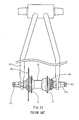
- A conventional rear hub for a bicycle in accordance with the prior art shown in
Figs. 9-11 comprises ashaft 40, ahub body 10 rotatably mounted on theshaft 40 by a plurality ofbearings 41 and provided with two protrudingspoke mounting portions 11, amounting ring 13 mounted on a first side of thehub body 10 and located beside one of the twospoke mounting portions 11, a drivenmember 12 mounted on a second side of thehub body 10 to drive and rotate thehub body 10 and located beside the other one of the twospoke mounting portions 11, abrake disc 30 mounted on themounting ring 13 of thehub body 10, and adrive member 20 rotatably mounted on theshaft 40 and engaged with the drivenmember 12 to drive and rotate the drivenmember 12. - The
shaft 40 has two opposite ends each provided with a threadedportion 42 for screwing alocking nut 43. Each of the twospoke mounting portions 11 of thehub body 10 has a periphery provided with a plurality offixing holes 110 for fixing a plurality of spokes (not shown) of a rear wheel (not shown). Thebrake disc 30 is used for clamping a brake (not shown) to produce a speed reduction function. Themounting ring 13 of thehub body 10 has a periphery provided with a plurality ofscrew bores 14, thebrake disc 30 is provided with a plurality of throughholes 31, and the hub further comprises a plurality oflocking screws 15 each extending through a respective one of the throughholes 31 of thebrake disc 30 and each screwed into a respective one of thescrew bores 14 of themounting ring 13. The drivenmember 12 has an inner wall provided with a plurality ofoneway ratchet teeth 120. Thedrive member 20 has a first end provided with aoneway ratchet wheel 21 meshing with theoneway ratchet teeth 120 of the drivenmember 12 and a second end provided with afreewheel 22. Thus, thedrive member 20 is rotatable to drive and rotate the drivenmember 12 in a oneway direction by engagement between theoneway ratchet wheel 21 and theoneway ratchet teeth 120 of the drivenmember 12 so as to drive and rotate thehub body 10 in a oneway direction. - As shown in
Fig. 11 , when theshaft 40 is mounted on arear frame 45 of the bicycle, thelocking nut 43 is rotated on the respective threadedportion 42 of theshaft 40 to press therear frame 45 onto thehub body 10 so as to attach thehub body 10 to therear frame 45. - In assembly, the
hub body 10 is connected to a rear wheel (not shown) of the bicycle, theshaft 40 is connected to therear frame 45 of the bicycle, thefreewheel 22 of thedrive member 20 is driven by a chain (not shown) which is driven by a chainwheel (not shown) which is driven by a pedal (not shown) that is pedalled by a rider. - In operation, when the
freewheel 22 of thedrive member 20 is rotated, thedrive member 20 is rotatable to drive and rotate the drivenmember 12 in a oneway direction by engagement between the onewayratchet wheel 21 of thedrive member 20 and theoneway ratchet teeth 120 of the drivenmember 12 to drive and rotate thehub body 10 in a oneway direction so as to drive and rotate the rear wheel in a oneway direction. - Thus, when the bicycle is used in an acrobatic place, the rear wheel is often inclined to be very close to the ground for performance of acrobatics. However, the
drive member 20 and thebrake disc 30 are located at the two opposite sides of thehub body 10 and have a projecting shape so that when the rear wheel is inclined to have a determined inclined angle, thedrive member 20 or thebrake disc 30 easily contacts raised equipments in the acrobatic place or even rubs the ground, thereby interfering with movement of the bicycle, and thereby easily wearing thedrive member 20 or thebrake disc 30. - The primary objective of the present invention is to provide a rear hub for a bicycle that is especially available for acrobatics.
- In accordance with the present invention, there is provided a hub, comprising a shaft, a hub body rotatably mounted on the shaft and provided with two protruding spoke mounting portions and a mounting ring located beside one of the two spoke mounting portions, a driven member mounted on the hub body to drive and rotate the hub body and located beside the mounting ring, a brake disc mounted on the mounting ring of the hub body, and a drive member rotatably mounted on the shaft and engaged with the driven member to drive and rotate the driven member.
- Another objective of the present invention is to provide a rear hub for a bicycle, wherein the drive member and the brake disc are located beside the one of the two spoke mounting portions of the hub body and are spaced from the other one of the two spoke mounting portions of the hub body so that the drive member and the brake disc are located at the same side of the hub body.
- A further objective of the present invention is to provide a rear hub for a bicycle, wherein the drive member and the brake disc are located at the same side of the hub body, so that one side of the hub body is provided with the drive member and the brake disc, and the other side of the hub body is disposed at a vacant state to facilitate a rider using the other side of the hub body to have a greater inclined angle without being obstructed by the drive member and the brake disc so as to perform acrobatics easily and smoothly.
- Further developments are described in the subclaims.
- Further benefits and advantages of the present invention will become apparent after a careful reading of the detailed description with appropriate reference to the accompanying drawings.
-
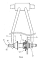
- Fig. 1
- is a perspective view of a rear hub in accordance with the preferred embodiment of the present inven-
tion. - Fig. 2
- is an exploded perspective view of the rear hub as shown in
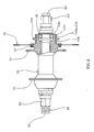
Fig. 1 . - Fig. 3
- is a front cross-sectional view of the rear hub as shown in Fig.l.
- Fig. 4
- is a front cross-sectional view of the rear hub for a bicycle as shown in
Fig. 3 . - Fig. 5
- is an exploded perspective view of a rear hub in accordance with another preferred embodiment of the present invention.
- Fig. 6
- is a front cross-sectional assembly view of the rear hub as shown in
Fig. 5 . - Fig. 7
- is an exploded perspective view of a rear hub in accordance with another preferred embodiment of the present invention.
- Fig. 8
- is a front cross-sectional assembly view of the rear hub as shown in
Fig. 7 . - Fig. 9
- is an exploded perspective view of a conventional rear hub in accordance with the prior art.
- Fig. 10
- is a front cross-sectional assembly view of the conventional rear hub as shown in
Fig. 9 . - Fig. 11
- is a front cross-sectional assembly view of the conventional rear hub for a bicycle as shown in
Fig. 9 . - Referring to the drawings and initially to
Figs. 1-3 , a rear hub for a bicycle in accordance with the preferred embodiment of the present invention comprises ashaft 80, ahub body 50 rotatably mounted on theshaft 80 by a plurality ofbearings 81 and provided with two protrudingspoke mounting portions 51 and amounting ring 52 located beside one of the twospoke mounting portions 51, a drivenmember 54 mounted on thehub body 50 to drive and rotate thehub body 50 and located beside themounting ring 52, abrake disc 70 mounted on themounting ring 52 of thehub body 50, and adrive member 60 rotatably mounted on theshaft 80 and engaged with the drivenmember 54 to drive and rotate the drivenmember 54. - In such a manner, the driven
member 54 and themounting ring 52 are located beside the one of the twospoke mounting portions 51 of thehub body 50 and are spaced from the other one of the twospoke mounting portions 51 of thehub body 50 so that the drivenmember 54 and themounting ring 52 are located at the same side of thehub body 50. Thus, thedrive member 60 and thebrake disc 70 are located beside the one of the twospoke mounting portions 51 of thehub body 50 and are spaced from the other one of the twospoke mounting portions 51 of thehub body 50 so that thedrive member 60 and thebrake disc 70 are located at the same side of thehub body 50. - The
shaft 80 has two opposite ends each provided with a threadedportion 82 for screwing alocking nut 83. Each of the twospoke mounting portions 51 of thehub body 50 has a periphery provided with a plurality offixing holes 510 for fixing a plurality of spokes (not shown) of a rear wheel (not shown). Thebrake disc 70 has a central portion provided with acentral hole 72, and thedrive member 60 extends through and protrudes outwardly from thecentral hole 72 of thebrake disc 70. Thebrake disc 70 is used for clamping a brake (not shown) to produce a speed reduction function. - The
mounting ring 52 of thehub body 50 has a periphery provided with a plurality ofscrew bores 520, thecentral hole 72 of thebrake disc 70 has a periphery provided with a plurality of throughholes 71, and the hub further comprises a plurality oflocking screws 53 each extending through a respective one of the throughholes 71 of thebrake disc 70 and each screwed into a respective one of thescrew bores 520 of themounting ring 52 of thehub body 50. - In the preferred embodiment of the present invention, the driven
member 54 is an annular body mounted in themounting ring 52 and located between the one of the twospoke mounting portions 51 of thehub body 50 and thebrake disc 70. The drivenmember 54 has an inner wall provided with a plurality ofoneway ratchet teeth 55. Thedrive member 60 has a first end provided with aoneway ratchet wheel 62 received in the drivenmember 54 and meshing with theoneway ratchet teeth 55 of the drivenmember 54 and second end provided with afreewheel 61. Thebrake disc 70 is located between the onewayratchet wheel 62 and thefreewheel 61 of thedrive member 60. Thus, thedrive member 60 is rotatable to drive and rotate the drivenmember 54 in a oneway direction by engagement between theoneway ratchet wheel 62 and theoneway ratchet teeth 55 of the drivenmember 54 so as to drive and rotate thehub body 50 in a oneway direction. - As shown in
Fig. 4 , when theshaft 80 is mounted on arear frame 90 of the bicycle, thelocking nut 83 is rotated on the respective threadedportion 82 of theshaft 80 to press therear frame 90 onto thehub body 50 so as to attach thehub body 50 to therear frame 90. - In assembly, the
hub body 50 is connected to a rear wheel (not shown) of the bicycle, theshaft 80 is connected to therear frame 90 of the bicycle, thefreewheel 61 of thedrive member 60 is driven by a chain (not shown) which is driven by a chainwheel (not shown) which is driven by a pedal (not shown) that is pedalled by a rider. - In operation, when the
freewheel 61 of thedrive member 60 is rotated normally, thedrive member 60 is rotatable to drive and rotate the drivenmember 54 in a oneway direction by engagement between the onewayratchet wheel 62 of thedrive member 60 and theoneway ratchet teeth 55 of the drivenmember 54 to drive and rotate thehub body 50 in a oneway direction so as to drive and rotate the rear wheel in a oneway direction. - Accordingly, the
drive member 60 and thebrake disc 70 are located beside the one of the twospoke mounting portions 51 of thehub body 50 and are spaced from the other one of the twospoke mounting portions 51 of thehub body 50 so that thedrive member 60 and thebrake disc 70 are located at the same side of thehub body 50. In addition, thedrive member 60 and thebrake disc 70 are located at the same side of thehub body 50, so that one side of thehub body 50 is provided with thedrive member 60 and thebrake disc 70, and the other side of thehub body 50 is disposed at a vacant state to facilitate a rider using the other side of thehub body 50 to have a greater inclined angle without being obstructed by thedrive member 60 and thebrake disc 70 so as to perform acrobatics easily and smoothly. - Referring to
Figs. 5 and6 , the drivenmember 54a is an annular protruding block protruding outwardly from themounting ring 52, and thebrake disc 70 is located between themounting ring 52 and the drivenmember 54a. The drivenmember 54a has an outer wall provided with an outer threadedsection 540a. Thedrive member 60a has an outer wall provided with afreewheel 61a and an inner wall provided with a rotatableoneway ratchet wheel 63a which has an inner wall provided with an inner threadedsection 64a screwed onto the outer threadedsection 540a of the drivenmember 54a. Theoneway ratchet wheel 63a of thedrive member 60a is located between thefreewheel 61a and the drivenmember 54a. Thus, thedrive member 60a is rotatable to drive and rotate the drivenmember 54a in a oneway direction by provision of theoneway ratchet wheel 63a so as to drive and rotate thehub body 50 in a oneway direction. Referring toFigs. 7 and8 , the drivenmember 54b is an annular protruding block protruding outwardly from the mountingring 52, and thebrake disc 70 is located between the mountingring 52 and the drivenmember 54b. The drivenmember 54b has an outer wall provided with a plurality ofelongate keys 540b. Thedrive member 60b has an outer wall provided with afreewheel 61b and an inner wall provided with a rotatableoneway ratchet wheel 63b which has an inner wall provided with a plurality ofkeyways 65b mounted on thekeys 540b of the drivenmember 54b. Theoneway ratchet wheel 63b of thedrive member 60b is located between thefreewheel 61b and the drivenmember 54b. Thus, thedrive member 60b is rotatable to drive and rotate the drivenmember 54b in a oneway direction by provision of theoneway ratchet wheel 63b so as to drive and rotate thehub body 50 in a oneway direction. - Although the invention has been explained in relation to its preferred embodiment(s) as mentioned above, it is to be understood that many other possible modifications and variations can be made without departing from the scope of the present invention. It is, therefore, contemplated that the appended claim or claims will cover such modifications and variations that fall within the true scope of the invention.
Claims (10)
- A hub, particularly a rear hub for a bicycle, comprising:a shaft (80);a hub body (50) rotatably mounted on the shaft and provided with two protruding spoke mounting portions (51) and a mounting ring (52) located beside one of the two spoke mounting portions;a driven member (54) mounted on the hub body to drive and rotate the hub body and located beside the mounting ring;a brake disc(70) mounted on the mounting ring of the hub body;a drive member (60) rotatably mounted on the shaft and engaged with the driven member to drive and rotate the driven member.
- The hub in accordance with claim 1, wherein
the driven member (54) and the mounting ring (52) are located beside the one of the two spoke mounting portions of the hub body and are spaced from the other one of the two spoke mounting portions of the hub body so that the driven member (54) and the mounting ring (50) are located at the same side of the hub body;
the drive member (60) and the brake disc (70) are located beside the one of the two spoke mounting portions of the hub body and are spaced from the other one of the two spoke mounting portions of the hub body so that the drive member (60) and the brake disc (70) are located at the same side of the hub body. - The hub in accordance with claim 1, wherein
the brake disc has a central portion provided
with a central hole (72);
the drive member extends through and protrudes
outwardly from the central hole of the brake
disc;
the mounting ring of the hub body has a periphery provided with a plurality of screw bores (520);
the central hole of the brake disc has a periphery provided with a plurality of through holes
(71);
the hub further comprises a plurality of locking-screws (53) each extending through a respective
one of the through holes of the brake disc and
each screwed into a respective one of the screw
bores of the mounting ring of the hub body. - The hub in accordance with claim 1, wherein the
driven member is an annular body mounted in the mounting ring and located between the one of the
two spoke mounting portions of the hub body and
the brake disc. - The hub in accordance with claim 4, wherein
the driven member has an inner wall provided with a plurality of oneway ratchet teeth (55);
the drive member has a first end provided with a oneway ratchet wheel (62) received in the driven member and meshing with the oneway ratchet teeth of the driven member and a second end provided with a freewheel (61). - The hub in accordance with claim 5, wherein the
brake disc is located between the oneway ratchet
wheel and the freewheel of the drive member. - The hub in accordance with claim 1, wherein the
driven member is an annular protruding block
protruding outwardly from the mounting ring;
the brake disc is located between the mounting
ring and the driven member. - The hub in accordance with claim 7, wherein the driven member (54a) has an outer wall provided with an outer threaded section (540a);
the drive member (60a) has an outer wall provided with a freewheel (61a) and an inner wall provided with a rotatable oneway ratchet wheel (63a) which has an inner wall provided with an inner threaded section (64a) screwed onto the outer threaded section of the driven member. - The hub in accordance with claim 8, wherein the
oneway ratchet wheel of the drive member is located between the freewheel and the driven member. - The hub in accordance with claim 7, wherein
the driven member (54b) has an outer wall provided with a plurality of elongate keys (540b);
the drive member (60b) has an outer wall provided with a freewheel (61b) and an inner wall
provided with a rotatable oneway ratchet wheel
(63b) which has an inner wall provided with a
plurality of keyways (65b) mounted on the keys
of the driven member.
Priority Applications (1)
| Application Number | Priority Date | Filing Date | Title |
|---|---|---|---|
| EP08000436A EP2078620A1 (en) | 2008-01-11 | 2008-01-11 | Hub, particularly a rear hub for a bicycle |
Applications Claiming Priority (1)
| Application Number | Priority Date | Filing Date | Title |
|---|---|---|---|
| EP08000436A EP2078620A1 (en) | 2008-01-11 | 2008-01-11 | Hub, particularly a rear hub for a bicycle |
Publications (1)
| Publication Number | Publication Date |
|---|---|
| EP2078620A1 true EP2078620A1 (en) | 2009-07-15 |
Family
ID=39401024
Family Applications (1)
| Application Number | Title | Priority Date | Filing Date |
|---|---|---|---|
| EP08000436A Withdrawn EP2078620A1 (en) | 2008-01-11 | 2008-01-11 | Hub, particularly a rear hub for a bicycle |
Country Status (1)
| Country | Link |
|---|---|
| EP (1) | EP2078620A1 (en) |
Cited By (1)
| Publication number | Priority date | Publication date | Assignee | Title |
|---|---|---|---|---|
| EP3492275A1 (en) * | 2017-11-29 | 2019-06-05 | Dndr Bvba | A wheel hub with disengagable brake system components |
Citations (7)
| Publication number | Priority date | Publication date | Assignee | Title |
|---|---|---|---|---|
| EP1270392A2 (en) * | 2001-06-29 | 2003-01-02 | Shimano Inc. | Bicycle disc brake hub |
| DE20304492U1 (en) * | 2003-03-20 | 2003-05-22 | Kun Teng Industry Co | Braking wheel hub device includes wheel hub cup with inner and outer revolving surface, and with right hand end face extending radially in order to run between inner and outer cup surface and standing opposite brake disc |
| DE202006000549U1 (en) * | 2006-01-14 | 2006-03-09 | Ming Cycle Industrial CO., LTD., Taiping | Hub for bicycle disk brake has hub body which is swivel mounted on bearing shaft and is provided with drum disks whereby chain wheel is screwed on thread section so that disk is wedged between assembly section and chain wheel |
| US20060219488A1 (en) * | 2005-03-29 | 2006-10-05 | Chun-Hsung Chen | Disc brake hub adapter structure |
| US20060284472A1 (en) * | 2005-06-16 | 2006-12-21 | Kun Teng Industry Co., Ltd. | Brakable wheel hub device |
| US20070132306A1 (en) * | 2005-12-14 | 2007-06-14 | Ming Cycle Industrial Co., Ltd. | Hub assembly for disk brake of bicycle |
| US20070241608A1 (en) * | 2006-04-13 | 2007-10-18 | Kun Teng Industry Co., Ltd. | Bicycle hub and assembly of bicycle hub and spokes |
-
2008
- 2008-01-11 EP EP08000436A patent/EP2078620A1/en not_active Withdrawn
Patent Citations (7)
| Publication number | Priority date | Publication date | Assignee | Title |
|---|---|---|---|---|
| EP1270392A2 (en) * | 2001-06-29 | 2003-01-02 | Shimano Inc. | Bicycle disc brake hub |
| DE20304492U1 (en) * | 2003-03-20 | 2003-05-22 | Kun Teng Industry Co | Braking wheel hub device includes wheel hub cup with inner and outer revolving surface, and with right hand end face extending radially in order to run between inner and outer cup surface and standing opposite brake disc |
| US20060219488A1 (en) * | 2005-03-29 | 2006-10-05 | Chun-Hsung Chen | Disc brake hub adapter structure |
| US20060284472A1 (en) * | 2005-06-16 | 2006-12-21 | Kun Teng Industry Co., Ltd. | Brakable wheel hub device |
| US20070132306A1 (en) * | 2005-12-14 | 2007-06-14 | Ming Cycle Industrial Co., Ltd. | Hub assembly for disk brake of bicycle |
| DE202006000549U1 (en) * | 2006-01-14 | 2006-03-09 | Ming Cycle Industrial CO., LTD., Taiping | Hub for bicycle disk brake has hub body which is swivel mounted on bearing shaft and is provided with drum disks whereby chain wheel is screwed on thread section so that disk is wedged between assembly section and chain wheel |
| US20070241608A1 (en) * | 2006-04-13 | 2007-10-18 | Kun Teng Industry Co., Ltd. | Bicycle hub and assembly of bicycle hub and spokes |
Cited By (1)
| Publication number | Priority date | Publication date | Assignee | Title |
|---|---|---|---|---|
| EP3492275A1 (en) * | 2017-11-29 | 2019-06-05 | Dndr Bvba | A wheel hub with disengagable brake system components |
Similar Documents
| Publication | Publication Date | Title |
|---|---|---|
| TWI779370B (en) | Bicycle hub assembly | |
| EP1964769B1 (en) | Bicycle rear sprocket assembly and sprocket | |
| EP1342657B1 (en) | Sprocket assembly for a bicycle | |
| US7938242B2 (en) | Bicycle hub that will not drive the pedal and will not produce noise when the hub is rotated in the backward direction | |
| US9580144B2 (en) | Sprocket assembly for a bicycle | |
| US6264575B1 (en) | Freewheel for a bicycle | |
| US7695073B1 (en) | Bicycle rear hub that is especially available for acrobatics | |
| US20020067069A1 (en) | Bicycle hub with threaded spacer and detachable freewheel | |
| US7445296B1 (en) | Bicycle hub having enhanced strength | |
| US6854569B2 (en) | Brakable wheel hub device | |
| US20120139327A1 (en) | Bicycle Hub Assembly | |
| US20060058140A1 (en) | A bicycle sprocket having a thickened spline | |
| US5433306A (en) | Hub assembly for a bicycle | |
| US20030153423A1 (en) | Bicycle chainring fastener system | |
| US8336694B2 (en) | Bicycle hub assembly with quickly switching function | |
| US8079288B2 (en) | Bicycle gear crank | |
| US20070254758A1 (en) | Hub assembly for bicycle | |
| US9855795B2 (en) | Clutch assembly | |
| US8474587B2 (en) | Bicycle hub assembly with two bearings | |
| EP2078620A1 (en) | Hub, particularly a rear hub for a bicycle | |
| US7766143B1 (en) | Bicycle rear hub whose freewheel having smaller diameter and specification | |
| EP2204291B1 (en) | Bicycle hub that will not drive the pedal and will not produce noise when the hub is rotated in the backward direction | |
| EP1930235B1 (en) | Pedalling device for bicycle | |
| US20120133199A1 (en) | Bicycle hub assembly with two transmission directions | |
| EP1629998B1 (en) | Rear hub assembly for a bicycle |
Legal Events
| Date | Code | Title | Description |
|---|---|---|---|
| PUAI | Public reference made under article 153(3) epc to a published international application that has entered the european phase |
Free format text: ORIGINAL CODE: 0009012 |
|
| 17P | Request for examination filed |
Effective date: 20080125 |
|
| AK | Designated contracting states |
Kind code of ref document: A1 Designated state(s): AT BE BG CH CY CZ DE DK EE ES FI FR GB GR HR HU IE IS IT LI LT LU LV MC MT NL NO PL PT RO SE SI SK TR |
|
| AX | Request for extension of the european patent |
Extension state: AL BA MK RS |
|
| 17Q | First examination report despatched |
Effective date: 20091001 |
|
| AKX | Designation fees paid |
Designated state(s): AT BE BG CH CY CZ DE DK EE ES FI FR GB GR HR HU IE IS IT LI LT LU LV MC MT NL NO PL PT RO SE SI SK TR |
|
| STAA | Information on the status of an ep patent application or granted ep patent |
Free format text: STATUS: THE APPLICATION IS DEEMED TO BE WITHDRAWN |
|
| 18D | Application deemed to be withdrawn |
Effective date: 20110802 |