EP3037232A1 - Sealed kneading machine - Google Patents
Sealed kneading machine Download PDFInfo
- Publication number
- EP3037232A1 EP3037232A1 EP14838198.1A EP14838198A EP3037232A1 EP 3037232 A1 EP3037232 A1 EP 3037232A1 EP 14838198 A EP14838198 A EP 14838198A EP 3037232 A1 EP3037232 A1 EP 3037232A1
- Authority
- EP
- European Patent Office
- Prior art keywords
- rotor
- mixing
- blades
- axis
- blade
- Prior art date
- Legal status (The legal status is an assumption and is not a legal conclusion. Google has not performed a legal analysis and makes no representation as to the accuracy of the status listed.)
- Granted
Links
Images


Classifications
-
- B—PERFORMING OPERATIONS; TRANSPORTING
- B29—WORKING OF PLASTICS; WORKING OF SUBSTANCES IN A PLASTIC STATE IN GENERAL
- B29B—PREPARATION OR PRETREATMENT OF THE MATERIAL TO BE SHAPED; MAKING GRANULES OR PREFORMS; RECOVERY OF PLASTICS OR OTHER CONSTITUENTS OF WASTE MATERIAL CONTAINING PLASTICS
- B29B7/00—Mixing; Kneading
- B29B7/02—Mixing; Kneading non-continuous, with mechanical mixing or kneading devices, i.e. batch type
- B29B7/22—Component parts, details or accessories; Auxiliary operations
- B29B7/26—Component parts, details or accessories; Auxiliary operations for discharging, e.g. doors
- B29B7/263—Component parts, details or accessories; Auxiliary operations for discharging, e.g. doors from the underside in mixers having more than one rotor and a a casing closely surrounding the rotors
-
- B—PERFORMING OPERATIONS; TRANSPORTING
- B29—WORKING OF PLASTICS; WORKING OF SUBSTANCES IN A PLASTIC STATE IN GENERAL
- B29B—PREPARATION OR PRETREATMENT OF THE MATERIAL TO BE SHAPED; MAKING GRANULES OR PREFORMS; RECOVERY OF PLASTICS OR OTHER CONSTITUENTS OF WASTE MATERIAL CONTAINING PLASTICS
- B29B7/00—Mixing; Kneading
- B29B7/02—Mixing; Kneading non-continuous, with mechanical mixing or kneading devices, i.e. batch type
- B29B7/06—Mixing; Kneading non-continuous, with mechanical mixing or kneading devices, i.e. batch type with movable mixing or kneading devices
- B29B7/10—Mixing; Kneading non-continuous, with mechanical mixing or kneading devices, i.e. batch type with movable mixing or kneading devices rotary
- B29B7/18—Mixing; Kneading non-continuous, with mechanical mixing or kneading devices, i.e. batch type with movable mixing or kneading devices rotary with more than one shaft
- B29B7/183—Mixing; Kneading non-continuous, with mechanical mixing or kneading devices, i.e. batch type with movable mixing or kneading devices rotary with more than one shaft having a casing closely surrounding the rotors, e.g. of Banbury type
-
- B—PERFORMING OPERATIONS; TRANSPORTING
- B29—WORKING OF PLASTICS; WORKING OF SUBSTANCES IN A PLASTIC STATE IN GENERAL
- B29B—PREPARATION OR PRETREATMENT OF THE MATERIAL TO BE SHAPED; MAKING GRANULES OR PREFORMS; RECOVERY OF PLASTICS OR OTHER CONSTITUENTS OF WASTE MATERIAL CONTAINING PLASTICS
- B29B7/00—Mixing; Kneading
- B29B7/02—Mixing; Kneading non-continuous, with mechanical mixing or kneading devices, i.e. batch type
- B29B7/06—Mixing; Kneading non-continuous, with mechanical mixing or kneading devices, i.e. batch type with movable mixing or kneading devices
- B29B7/10—Mixing; Kneading non-continuous, with mechanical mixing or kneading devices, i.e. batch type with movable mixing or kneading devices rotary
- B29B7/18—Mixing; Kneading non-continuous, with mechanical mixing or kneading devices, i.e. batch type with movable mixing or kneading devices rotary with more than one shaft
- B29B7/183—Mixing; Kneading non-continuous, with mechanical mixing or kneading devices, i.e. batch type with movable mixing or kneading devices rotary with more than one shaft having a casing closely surrounding the rotors, e.g. of Banbury type
- B29B7/186—Rotors therefor
-
- B—PERFORMING OPERATIONS; TRANSPORTING
- B29—WORKING OF PLASTICS; WORKING OF SUBSTANCES IN A PLASTIC STATE IN GENERAL
- B29B—PREPARATION OR PRETREATMENT OF THE MATERIAL TO BE SHAPED; MAKING GRANULES OR PREFORMS; RECOVERY OF PLASTICS OR OTHER CONSTITUENTS OF WASTE MATERIAL CONTAINING PLASTICS
- B29B7/00—Mixing; Kneading
- B29B7/02—Mixing; Kneading non-continuous, with mechanical mixing or kneading devices, i.e. batch type
- B29B7/22—Component parts, details or accessories; Auxiliary operations
- B29B7/24—Component parts, details or accessories; Auxiliary operations for feeding
- B29B7/246—Component parts, details or accessories; Auxiliary operations for feeding in mixers having more than one rotor and a casing closely surrounding the rotors, e.g. with feeding plungers
-
- B—PERFORMING OPERATIONS; TRANSPORTING
- B29—WORKING OF PLASTICS; WORKING OF SUBSTANCES IN A PLASTIC STATE IN GENERAL
- B29B—PREPARATION OR PRETREATMENT OF THE MATERIAL TO BE SHAPED; MAKING GRANULES OR PREFORMS; RECOVERY OF PLASTICS OR OTHER CONSTITUENTS OF WASTE MATERIAL CONTAINING PLASTICS
- B29B7/00—Mixing; Kneading
- B29B7/74—Mixing; Kneading using other mixers or combinations of mixers, e.g. of dissimilar mixers ; Plant
- B29B7/7476—Systems, i.e. flow charts or diagrams; Plants
- B29B7/7495—Systems, i.e. flow charts or diagrams; Plants for mixing rubber
Definitions
- the present invention relates to an internal mixer.
- An internal mixer includes a mixing chamber to which a mixing material is supplied and a rotor arranged within the mixing chamber.
- the rotor includes a plurality of mixing blades for mixing the mixing material. By the rotor being rotated, the mixing blade mixes the mixing material.
- Patent Document 2 a technique intended to obtain a mixed product of a favorable quality by causing the size of a gap (tip clearance) between an apex section of a mixing blade and the inner surface of a mixing chamber to be a predetermined value is described.
- paragraph [0035] of the same document it is described that the length of a mixing blade (13, 14) in the rotor axis direction is set to 0.7W or 0.65W with respect to an entire length (W) of a rotor in the rotor axis direction.
- An object of the present invention is to provide an internal mixer that can improve the performance for distribution of a mixing material, can shorten the mixing time of a mixing material, and can improve the productivity with the internal mixer.
- An internal mixer includes: a mixing chamber to which a mixing material is supplied; and a rotor arranged within the mixing chamber to be freely rotatable about a rotor axis, wherein the rotor includes a plurality of mixing blades for mixing the mixing material, and each length of all of the mixing blades in a rotor axis direction is 45% or less of an entire length of the rotor in the rotor axis direction.
- the internal mixer 1 is a device that performs mixing of a mixing material.
- the mixing material is, for example, a polymeric material.
- the polymeric material is, for example, rubber or resin.
- the mixing material consists of, for example, a combination or the like of silica, silane coupling agent, and the like with rubber.
- the internal mixer 1 is of a batch type.
- the internal mixer 1 includes a supply section 10 and a mixing section 30.
- the supply section 10 is a section that supplies a mixing material to the mixing section 30.
- the supply section 10 includes a hopper 11, a material supply cylinder 13, and a cylinder device 20.
- a mixing material is put into the hopper 11 from outside the internal mixer 1.
- the material supply cylinder 13 is a cylinder through which a mixing material is passable. An upper section of a space in the material supply cylinder 13 communicates with a space in the hopper 11.
- the cylinder device 20 is a device that pushes a mixing material into the mixing section 30 (a mixing chamber 33 described later) from the material supply cylinder 13.
- the cylinder device 20 is a telescopic type actuator.
- the cylinder device 20 is, for example, a pneumatic type actuator.
- the cylinder device 20 is arranged above the material supply cylinder 13.
- the cylinder device 20 includes a cylinder 21, a piston 23, a piston rod 25, and a floating weight 27.
- the cylinder 21 is a cylinder-shaped member.
- the piston 23 is a member capable of a reciprocating motion within the cylinder 21.
- the piston rod 25 is a rod coupled to the piston 23.
- the piston rod 25 penetrates a bottom lid of the cylinder 21 (portion of a lid at the lower end of the cylinder 21) in an airtight manner.
- the floating weight 27 is a member that pushes a mixing material to the mixing section 30 side (to the lower side) from the supply section 10.
- the floating weight 27 is arranged within the material supply cylinder 13.
- the floating weight 27 is coupled to the piston rod 25.
- the floating weight 27 is freely movable in the axis direction (vertical direction) of the material supply cylinder 13.
- the mixing section 30 is a portion that mixes a mixing material.
- the mixing section 30 is arranged beneath the supply section 10 and coupled to the supply section 10.
- the mixing section 30 includes a chamber 31, a drop door 35, and rotors 40 and 50.
- the chamber 31 is a portion inside which the mixing chamber 33 is formed.
- an upper section supply opening for communication of a lower section of the space in the material supply cylinder 13 and the mixing chamber 33 is formed.
- a bottom section discharge opening for communication of the outside of the internal mixer 1 and the mixing chamber 33 is formed.
- the mixing chamber 33 is a space (segment) to which a mixing material is supplied.
- the mixing chamber 33 is a space in which a mixing material is mixed.
- the vertical sectional surface of the mixing chamber 33 is of a cocoon shape. The vertical sectional surface corresponds to a sectional surface when seen from a rotor axis direction Z (see Fig. 2 ) described later.
- the drop door 35 opens and closes (opens and shuts) the bottom section discharge opening of the chamber 31.
- the drop door 35 opens and closes the bottom section discharge opening by being driven by an actuator.
- the actuator that drives the drop door 35 is, for example, a rotating type actuator (rotary actuator) or the like.
- the rotors 40 and 50 are arranged within the mixing chamber 33. Each rotors 40 and 50 has an approximately cylindrical shape. The two rotors 40 and 50 are arranged within the mixing chamber 33. That is, the internal mixer 1 is of a biaxial type.
- the central axis of the rotor 40 (central axis of an approximate cylinder) corresponds to a rotor axis 40a of the rotor 40.
- the central axis of the rotor 50 central axis of an approximate cylinder
- the rotor 40 and the rotor 50 each include mixing blades 61 to 66.
- the two rotors 40 and 50 are provided as a left and right pair, so to speak. As shown in Fig. 1 , the rotor 40 and the rotor 50 are arranged such that the rotor axis 40a and the rotor axis 50a are parallel. The rotor axis 40a and the rotor axis 50a are arranged on the same plane parallel to the horizontal plane. The rotor 40 and the rotor 50 are arranged with an interval in between. Note that the number of the rotor included in the internal mixer 1 may be only one. That is, the internal mixer 1 may be of a uniaxial type. Hereinafter, a case where the internal mixer 1 includes the two rotors 40 and 50 will be described.
- the two rotors 40 and 50 rotate in directions different from each other, such that inside portions of the rotors 40 and 50 move downward.
- the inside portions of the rotors 40 and 50 correspond to portions of the rotors 40 and 50 located between the rotor axis 40a and the rotor axis 50a.
- the rotor 40 is freely rotatable about the rotor axis 40a.
- the rotor 50 is freely rotatable about the rotor axis 50a.
- the respective mixing blades 61 to 66 of the two rotors 40 and 50 do not mesh with each other. That is, the internal mixer 1 is of a non-meshing type.
- the development shapes of the two rotors 40 and 50 are point symmetric with each other, as shown in Fig. 3 . More specifically, the shape of the rotor 40 upon development around the rotor axis 40a (see Fig. 1 ) of the rotor 40 is a development shape D40, and the shape of the rotor 50 upon development around the rotor axis 50a (see Fig. 1 ) of the rotor 50 is a development shape D50. Then, the development shape D40 and the development shape D50 are point symmetric with each other with respect to a center point O.
- the arrangement of the mixing blades 61 to 66 in the development shape D40 and the arrangement of the mixing blades 61 to 66 in the development shape D50 are point symmetric with each other with respect to the center point O.
- only one rotor 50 out of the two rotors 40 and 50 will be described, and description of the rotor 40 will be omitted.
- the rotating direction of the rotor 50 shown in Fig. 2 is a rotor rotating direction R. That is, a direction around the rotor axis 50a and a circumferential direction of the approximately cylinder-shaped rotor 50 are the rotor rotating direction R.
- the front side upon rotation of the rotor 50 is a front side Rf
- the rear side upon rotation of the rotor 50 is a rear side Rr.
- An extension direction of the rotor axis 50a of the rotor 50 is the rotor axis direction Z.
- One side in the rotor axis direction Z is a first axis end side Z1.
- the other side in the rotor axis direction Z is a second axis end side Z2. That is, an opposite side of the first axis end side Z1 in the rotor axis direction Z is the second axis end side Z2.
- the entire length of the rotor 50 in the rotor axis direction Z is an entire length W.
- the first axis end 51 is one end section of the rotor 50 in the rotor axis direction Z.
- the first axis end 51 is an end section of the rotor 50 on the first axis end side Z1.
- the second axis end 52 is the other end section of the rotor 50 in the rotor axis direction Z.
- the second axis end 52 is an end section of the rotor 50 on the second axis end side Z2. That is, the second axis end 52 is an end section on an opposite side of the first axis end 51 in the rotor axis direction Z.
- the mixing blades 61 to 66 are blades (wings) for mixing a mixing material.
- the rotor 50 is provided with a plurality of the mixing blades 61 to 66. Specifically, the number of the mixing blades 61 to 66 of one rotor 50 is six. The number of the mixing blades 61 to 66 of one rotor 50 may be 7 or greater and 5 or less (not shown in the drawing).
- the mixing blades 61 to 66 are configured such that gaps (tip clearances) are formed between the inner surface of the chamber 31 and apex sections of the mixing blades 61 to 66, the inner surface surrounding the mixing chamber 33 (see Fig. 1 ).
- the apex sections are tip end sections of the mixing blades 61 to 66.
- the tip end sections of the mixing blades 61 to 66 are outside end sections of the mixing blades 61 to 66 in the diameter direction of the approximately cylinder-shaped rotor 50.
- the mixing blades 61 to 66 are configured to give a shear force to a mixing material that passes through the tip clearance at the time of rotation of the rotor 50.
- the mixing blades 61 to 66 are configured to push a mixing material at the time of rotation of the rotor 50, so that the mixing material moves (flows) in the rotor axis direction Z.
- the mixing blades 61 to 66 are of a shape twisted in a spiral manner with the rotor axis 50a as the central axis.
- the apex section of the mixing blades 61 to 66 is spiral-shaped with the rotor axis 50a as the central axis.
- (all of) the mixing blades 61 to 66 are linear blades.
- a linear blade is a blade that is linear (linear-shaped) in the development shape D50 of the rotor 50. Note that at least a part of the mixing blades 61 to 66 may be a non-linear blade (not shown in the drawing).
- a length Lz of all mixing blades 61 to 66 in the rotor axis direction Z is 45% or less of the entire length W of the rotor 50 (Lz ⁇ 0.45W) in the rotor axis direction Z.
- a length Lz1 of the respective mixing blades 61 and 62 is 45% or less of the entire length W.
- a length Lz3 of the respective mixing blades 63 and 64 is 45% or less of the entire length W.
- a length Lz5 of the respective mixing blades 65 and 66 is 45% or less of the entire length W.
- the plurality of mixing blades 61 to 66 there are blades whose starting points (described later) are arranged at axis ends (the first axis end 51 and the second axis end 52) different from each other. Specifically, as shown in Fig. 3 , there are first axis end side blades (the mixing blades 61 and 62) and second axis end side blades (the mixing blades 63 and 64) in the plurality of mixing blades 61 to 66. Also, in the plurality of mixing blades 61 to 66, there are middle blades (the mixing blades 65 and 66) not in contact with either the first axis end 51 or the second axis end 52.
- the first axis end side blades are blades whose end sections (starting points 61s and 62s) on the front side Rf in the rotor rotating direction R are arranged at the first axis end 51.
- the first axis end side blades are blades that feed a mixing material to the second axis end side Z2 from the first axis end 51 at the time of rotation of the rotor 50.
- a plurality (two or more) of the first axis end side blades (mixing blades 61 and 62) are provided.
- the two first axis end side blades are provided.
- the lengths Lz1 of the two first axis end side blades (mixing blades 61 and 62) are identical with each other.
- the angles of the two first axis end side blades (mixing blades 61 and 62) with respect to the rotor rotating direction R are identical with each other.
- the second axis end side blades are blades whose end sections (starting points 63s and 64s) on the front side Rf in the rotor rotating direction R are arranged at the second axis end 52.
- the second axis end side blades (mixing blades 63 and 64) feed a mixing material to the first axis end side Z1 from the second axis end 52 at the time of rotation of the rotor 50.
- a plurality of the second axis end side blades (mixing blades 63 and 64) are provided. For example, two are provided.
- the lengths Lz3 of the two second axis end side blades (mixing blades 63 and 64) are identical with each other.
- the middle blades are arranged only on the second axis end side Z2 relative to the first axis end 51 and arranged only on the first axis end side Z1 relative to the second axis end 52.
- the middle blades (mixing blades 65 and 66) are arranged on the second axis end side Z2 of the first axis end side blades (mixing blades 61 and 62).
- the middle blades (mixing blades 65 and 66) are arranged on the first axis end side Z1 of the second axis end side blades (mixing blades 63 and 64).
- the middle blades (mixing blades 65 and 66) feed a mixing material to the second axis end side Z2 toward the second axis end side blades (mixing blades 63 and 64) from the first axis end side blades (mixing blades 61 and 62) at the time of rotation of the rotor 50.
- the middle blades (mixing blades 65 and 66) may be configured to feed a mixing material to the first axis end side Z1 at the time of rotation of the rotor 50 (not shown in the drawing).
- a plurality of the middle blades (mixing blades 65 and 66) are provided.
- the two middle blades are provided.
- the lengths Lz5 of the two middle blades (mixing blades 65 and 66) are identical with each other.
- the plurality of mixing blades 61 to 66 there are blades whose lengths Lz are different from each other.
- the plurality of mixing blades 61 to 66 include a short blade and a long blade whose length Lz is greater than the length of the short blade.
- the length Lz5 of the middle blades (mixing blades 65 and 66) is greater than the length Lz1 of the first axis end side blades (mixing blades 61 and 62) and greater than the length Lz3 of the second axis end side blades (mixing blades 63 and 64).
- the length Lz3 of the second axis end side blades (mixing blades 63 and 64) is greater than the length Lz1 of the first axis end side blades (mixing blades 61 and 62).
- a plurality of the short blades (e.g., mixing blades 61 and 62) are provided.
- the two short blades are provided.
- a plurality of the long blades (e.g., mixing blades 63 and 64) are provided.
- the two long blades are provided.
- the plurality of mixing blades 61 to 66 are arranged with an interval (space) in between from each other in the rotor rotating direction R. Specifically, there are a front blade and a rear blade in the plurality of mixing blades 61 to 66.
- the front blade is the mixing blade 63.
- the front blade (mixing blade 63) includes a front blade end point 63e.
- the front blade end point 63e is a rear side Rr end section of the front blade (mixing blade 63) in the rotor rotating direction R.
- the rear blade (mixing blade 65) is adjacent to the front blade end point 63e on the rear side Rr (immediately in the rear).
- the rear blade (mixing blade 65) and the front blade end point 63e are arranged with an interval ⁇ 1 in between from each other in the rotor rotating direction R.
- the interval ⁇ 1 is given between the front blade end point 63e and a portion of the rear blade (mixing blade 65) which is located immediately in the rear of the front blade end point 63e in the rotor rotating direction R.
- the size of the interval ⁇ 1 corresponds to a predetermined phase difference around the rotor axis 50a (see Fig. 2 ) within a range of 40° to 160°. In other word, the size of the interval ⁇ 1 corresponds to a predetermined phase difference around the rotor axis 50a which is 40° or greater and 160° or less.
- the front blade when the front blade is the mixing blade 65, the rear blade is the mixing blade 64.
- the front blade (mixing blade 65) includes a front blade end point 65e.
- the front blade end point 65e is a rear side Rr end section of the front blade (mixing blade 65) in the rotor rotating direction R.
- the rear blade (mixing blade 64) is adjacent to a front blade end point 65e on the rear side Rr (immediately in the rear).
- the rear blade (mixing blade 64) and the front blade end point 65e are arranged with an interval ⁇ 2 in between from each other in the rotor rotating direction R.
- the interval ⁇ 2 is given between the front blade end point 65e and a portion of the rear blade (mixing blade 64) which is located immediately in the rear of the front blade end point 65e in the rotor rotating direction R.
- the interval ⁇ 2 between the rear blade (mixing blade 64) and the front blade end point 65e in the rotor rotating direction R corresponds to a predetermined phase difference around the rotor axis 50a (see Fig. 2 ) within a range of 40° to 160°.
- phase difference holds among all mixing blades 61 to 66, for example.
- the operation of the internal mixer 1 shown in Fig. 1 is as in the following (a) to (h).
- (a) The drop door 35 is caused to firmly contact the chamber 31. As a result, the bottom section discharge opening of the chamber 31 is closed.
- (b) A lower section of the cylinder 21 is applied with pressure. As a result, the floating weight 27 moves (ascends) to the supply section 10 side from the chamber 31. As a result, the upper section supply opening of the chamber 31 is opened.
- a mixing material is supplied into the material supply cylinder 13 via the hopper 11 from outside the internal mixer 1.
- An upper section of the cylinder 21 is applied with pressure. As a result, the floating weight 27 moves (descends) to the mixing section 30 side.
- the mixing material is pushed (loaded or injected) into the mixing chamber 33 from within the material supply cylinder 13.
- the upper section supply opening of the chamber 31 is closed by the floating weight 27.
- the rotors 40 and 50 rotate in opposite directions from each other.
- a shear force is applied to the mixing material when the mixing material passes through the gaps (tip clearances) between the inner surface of the chamber 31 and the apex sections of the mixing blades 61 to 66 (see Fig. 2 ).
- the mixing material moves in the rotor axis direction Z.
- the mixing material moves between the two rotors 40 and 50.
- the mixing material is dispersed uniformly.
- the mixing material comes to a desired mixed state.
- the drop door 35 is detached (isolated) from the chamber 31. As a result, the bottom section discharge opening of the chamber 31 is opened. As a result, a mixed product (mixed mixing material) is discharged outside the internal mixer 1.
- the mixing blades (61 to 66) used in the evaluation of the distribution performance are as in the following (A) to (C).
- the three types of mixing blades 61 to 66 of (C1), (C2), and (C3) described above are all linear blades.
- a mixing material is that in which beads are put into a 30% aqueous solution of carboxymethyl cellulose (CMC).
- Fig. 4 is a graph showing the relationship of the mixing time (abscissa) and the CV value (ordinate).
- Fig. 5 and Fig. 6 are graphs showing the relationship of the mixing time and the CV value as well. CV stands for coefficient of variation. Details of the CV value will be described later.
- the mixing performance improves in the case where the length Lz of all mixing blades 61 to 66 is 45% or less of the entire length W of the rotors 40 and 50 relative to a case of Conventional Technique 1 or (B: [49%]) described above.
- the distribution performance improved when the length Lz with respect to the entire length W is shorter. Specifically, it was found that the distribution performance improved in the order of (C1: [45%]), (C2, [43%], and (C3: [40%]).
- the CV value is a value as an index representing the degree of dispersion of a component in a mixing material.
- a lower CV value represents that the dispersion is progressing (in other words, mixing of a mixing material is being accelerated).
- the CV value is obtained with the following expression (1).
- CV is the CV value.
- M is an average value of the mass fraction of a component within a mixing material accommodated within the mixing chamber 33 (see Fig. 1 ) .
- ⁇ is the standard deviation of the mass fraction of the component within the mixing material accommodated within the mixing chamber 33.
- the combination content of a mixing material is as in Table 1.
- Table 1 Component PHR SBR 96.25 BR 30 Carbon 85 Alternative aroma oil 20 Zinc oxide 3 Stearic acid 2 Antioxidant 1 Sulfur 1.5 Vulcanization accelerator 1.2
- the PHR (parts per hundred rubber) in Table 1 is the parts by weight of various compounding agents with respect to a rubber weight of 100.
- the SBR is styrene-butadiene rubber.
- the BR is butadiene rubber.
- the internal mixer 1 includes the mixing chamber 33 to which a mixing material is supplied and the rotor 50 arranged within the mixing chamber 33 to be freely rotatable about the rotor axis 50a.
- the rotor 50 includes the plurality of mixing blades 61 to 66 for mixing a mixing material.
- a length Lz of all of the mixing blades 61 to 66 in the rotor axis direction Z is 45% or less of the entire length W of the rotor 50 in the rotor axis direction Z.
- the distribution performance can be improved (see Experiment 1 and Experiment 2 described above) relative to Conventional Technique 1 or the like described above (Conventional Technique 1 and that whose length Lz exceeds 45% with respect to the entire length W).
- a mixing material can be brought to a desired mixed state in less time than in Conventional Technique 1 or the like.
- the mixing time (mixing time) of a mixing material can be shortened.
- the productivity with the internal mixer 1 can be improved relative to Conventional Technique 1 or the like.
- the plurality of mixing blades 61 to 66 include a short blade (e.g., the mixing blades 61 and 62) and a long blade (e.g., the mixing blades 63 and 64) whose length Lz in the rotor axis direction Z is greater than the length of the short blade (e.g., mixing blades 61 and 62) in the rotor axis direction Z.
- a short blade e.g., the mixing blades 61 and 62
- a long blade e.g., the mixing blades 63 and 64
- the flow of a mixing material is complicated compared to a case where there is only one type of the length Lz of the plurality of mixing blades 61 to 66.
- the flow of a mixing material is complicated compared to a case where only one short blade (e.g., the mixing blade 61 or 62) is provided or a case where only one long blade (e.g., the mixing blade 63 or 64) is provided.
- the performance for distribution of a mixing material can further be improved.
- the mixing time of a mixing material can be shortened.
- the productivity with the internal mixer 1 can be further improved.
- the rotor 50 includes the first axis end 51 that is one end section of the rotor 50 in the rotor axis direction Z and the second axis end 52 that is the other end section of the rotor 50 in the rotor axis direction Z. As shown in Fig. 3 , there are the first axis end side blades (mixing blades 61 and 62) and the second axis end side blades (mixing blades 63 and 64) in the plurality of mixing blades 61 to 66.
- the first axis end side blades are blades whose front end sections (front side Rf end sections, starting points 61s and 62s) in the rotor rotating direction R are arranged at the first axis end 51.
- the second axis end side blades are blades whose front end sections (front side Rf end sections, starting points 63s and 64s) in the rotor rotating direction R are arranged at the second axis end 52.
- the rotor 50 includes the first axis end 51 and the second axis end 52.
- the front blade e. g. , mixing blade 63
- the rear blade e. g. , mixing blade 65
- the rear blade (mixing blade 65) is adjacent, on the rear side Rr in the rotor rotating direction R, to the front blade end point 63e that is a rear end section of the front blade (mixing blade 63) in the rotor rotating direction R.
- the front blade end point 63e and the rear blade (mixing blade 65) are arranged with an interval ⁇ 1 in between from each other in the rotor rotating direction R.
- the size of the interval ⁇ 1 corresponds to a predetermined phase difference around the rotor axis 50a (see Fig. 2 ) within a range of 40° to 160°.
- the mixing blades 61 to 66 can be made easily, compared to a case where the development shape of at least a part of the mixing blades 61 to 66 is non-linear (see Conventional Technique 1 described above). Nevertheless, as in (Effect 1) described above, the performance for distribution of a mixing material can be improved compared to Conventional Technique 1.
- the internal mixer includes: a mixing chamber to which a mixing material is supplied; and a rotor arranged within the mixing chamber to be freely rotatable about a rotor axis.
- the rotor includes a plurality of mixing blades for mixing the mixing material, and each length of all of the mixing blades in a rotor axis direction is 45% or less of an entire length of the rotor in the rotor axis direction.
- the plurality of mixing blades include: two or more of short blades; and two or more of long blades, wherein any of respective lengths of the long blades in the rotor axis direction is greater than any of respective lengths of the short blades in the rotor axis direction.
- the rotor includes: a first axis end that is one end section of the rotor in the rotor axis direction; and a second axis end that is another end section of the rotor in the rotor axis direction
- the plurality of mixing blades include: a first axis end side blade whose front end section in a rotating direction of the rotor is arranged at the first axis end; and a second axis end side blade whose front end section in the rotating direction of the rotor is arranged at the second axis end.
- the rotor includes: a first axis end that is one end section of the rotor in the rotor axis direction; and a second axis end that is another end section of the rotor in the rotor axis direction, and the plurality of mixing blades include a middle blade arranged only on the second axis end side relative to the first axis end and arranged only on the first axis end side relative to the second axis end.
- the plurality of mixing blades include: a front blade; and a rear blade adjacent, on a rear side in a rotating direction of the rotor, to a front blade end point that is a rear end section of the front blade in the rotating direction of the rotor, the front blade end point and the rear blade are spaced in the rotating direction of the rotor, and a size of an interval between the front blade end point and the rear blade corresponds to a predetermined phase difference around the rotor axis within a range of 40° to 160°.
- the performance for distribution of a mixing material can be improved, the mixing time of a mixing material can be shortened, and the productivity with the internal mixer can be improved.
Landscapes
- Engineering & Computer Science (AREA)
- Mechanical Engineering (AREA)
- Processing And Handling Of Plastics And Other Materials For Molding In General (AREA)
- Mixers Of The Rotary Stirring Type (AREA)
Abstract
Description
- The present invention relates to an internal mixer.
- Conventionally, there have been internal mixers (refer to
Patent Documents - [Conventional Technique 1] In Patent Document 1 (see
Fig. 2 andFig. 4 of the same document), a technique intended to achieve both distributivity and dispersibility of a mixing material with a non-linear blade (13) is described. In paragraph [0017] of the same document, it is described that the length of a mixing blade (12, 13) in the rotor axis direction is set to 0.65L or 0.7L with respect to an entire length (L) of a rotor in the rotor axis direction. - [Conventional Technique 2] In
Patent Document 2, a technique intended to obtain a mixed product of a favorable quality by causing the size of a gap (tip clearance) between an apex section of a mixing blade and the inner surface of a mixing chamber to be a predetermined value is described. In paragraph [0035] of the same document, it is described that the length of a mixing blade (13, 14) in the rotor axis direction is set to 0.7W or 0.65W with respect to an entire length (W) of a rotor in the rotor axis direction. - In the internal mixers of
Conventional Techniques Conventional Techniques -
- Patent Document 1: Japanese Patent Application Laid-open No.
2002-11336 - Patent Document 2: Japanese Patent No.
4568785 - An object of the present invention is to provide an internal mixer that can improve the performance for distribution of a mixing material, can shorten the mixing time of a mixing material, and can improve the productivity with the internal mixer.
- An internal mixer according to one aspect of the present invention includes: a mixing chamber to which a mixing material is supplied; and a rotor arranged within the mixing chamber to be freely rotatable about a rotor axis, wherein the rotor includes a plurality of mixing blades for mixing the mixing material, and each length of all of the mixing blades in a rotor axis direction is 45% or less of an entire length of the rotor in the rotor axis direction.
-
-
Fig. 1 is a sectional view of aninternal mixer 1. -
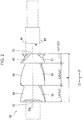
Fig. 2 is an overall view of arotor 50 shown inFig. 1 . -
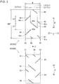
Fig. 3 is a development view of arotor 40 and therotor 50 shown inFig. 1 . -
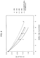
Fig. 4 is a graph showing the relationship of the mixing time and the CV value. -
Fig. 5 is a graph showing the relationship of the mixing time and the CV value. -
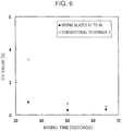
Fig. 6 is a graph showing the relationship of the mixing time and the CV value. - Referring to
Fig. 1 to Fig. 6 , aninternal mixer 1 shown inFig. 1 will be described. - The
internal mixer 1 is a device that performs mixing of a mixing material. The mixing material is, for example, a polymeric material. The polymeric material is, for example, rubber or resin. The mixing material consists of, for example, a combination or the like of silica, silane coupling agent, and the like with rubber. Theinternal mixer 1 is of a batch type. Theinternal mixer 1 includes asupply section 10 and amixing section 30. - The
supply section 10 is a section that supplies a mixing material to themixing section 30. Thesupply section 10 includes ahopper 11, amaterial supply cylinder 13, and acylinder device 20. - A mixing material is put into the
hopper 11 from outside theinternal mixer 1. - The
material supply cylinder 13 is a cylinder through which a mixing material is passable. An upper section of a space in thematerial supply cylinder 13 communicates with a space in thehopper 11. - The
cylinder device 20 is a device that pushes a mixing material into the mixing section 30 (amixing chamber 33 described later) from thematerial supply cylinder 13. Thecylinder device 20 is a telescopic type actuator. Thecylinder device 20 is, for example, a pneumatic type actuator. Thecylinder device 20 is arranged above thematerial supply cylinder 13. Thecylinder device 20 includes acylinder 21, apiston 23, apiston rod 25, and a floatingweight 27. - The
cylinder 21 is a cylinder-shaped member. Thepiston 23 is a member capable of a reciprocating motion within thecylinder 21. - The
piston rod 25 is a rod coupled to thepiston 23. Thepiston rod 25 penetrates a bottom lid of the cylinder 21 (portion of a lid at the lower end of the cylinder 21) in an airtight manner. - The floating
weight 27 is a member that pushes a mixing material to themixing section 30 side (to the lower side) from thesupply section 10. The floatingweight 27 is arranged within thematerial supply cylinder 13. The floatingweight 27 is coupled to thepiston rod 25. Thefloating weight 27 is freely movable in the axis direction (vertical direction) of thematerial supply cylinder 13. - The
mixing section 30 is a portion that mixes a mixing material. Themixing section 30 is arranged beneath thesupply section 10 and coupled to thesupply section 10. Themixing section 30 includes achamber 31, adrop door 35, androtors - The
chamber 31 is a portion inside which themixing chamber 33 is formed. At an upper section of thechamber 31, an upper section supply opening for communication of a lower section of the space in thematerial supply cylinder 13 and themixing chamber 33 is formed. At a bottom section of thechamber 31, a bottom section discharge opening for communication of the outside of theinternal mixer 1 and themixing chamber 33 is formed. - The
mixing chamber 33 is a space (segment) to which a mixing material is supplied. Themixing chamber 33 is a space in which a mixing material is mixed. The vertical sectional surface of themixing chamber 33 is of a cocoon shape. The vertical sectional surface corresponds to a sectional surface when seen from a rotor axis direction Z (seeFig. 2 ) described later. - The
drop door 35 opens and closes (opens and shuts) the bottom section discharge opening of thechamber 31. Thedrop door 35 opens and closes the bottom section discharge opening by being driven by an actuator. The actuator that drives thedrop door 35 is, for example, a rotating type actuator (rotary actuator) or the like. - The
rotors 40 and 50 (mixing rotors) are arranged within the mixingchamber 33. Eachrotors rotors chamber 33. That is, theinternal mixer 1 is of a biaxial type. The central axis of the rotor 40 (central axis of an approximate cylinder) corresponds to arotor axis 40a of therotor 40. The central axis of the rotor 50 (central axis of an approximate cylinder) corresponds to arotor axis 50a of therotor 50. As shown inFig. 3 , therotor 40 and therotor 50 each include mixingblades 61 to 66. - The two
rotors Fig. 1 , therotor 40 and therotor 50 are arranged such that therotor axis 40a and therotor axis 50a are parallel. Therotor axis 40a and therotor axis 50a are arranged on the same plane parallel to the horizontal plane. Therotor 40 and therotor 50 are arranged with an interval in between. Note that the number of the rotor included in theinternal mixer 1 may be only one. That is, theinternal mixer 1 may be of a uniaxial type. Hereinafter, a case where theinternal mixer 1 includes the tworotors - The two
rotors rotors rotors rotors rotor axis 40a and therotor axis 50a. Therotor 40 is freely rotatable about therotor axis 40a. Therotor 50 is freely rotatable about therotor axis 50a. - The
respective mixing blades 61 to 66 of the tworotors internal mixer 1 is of a non-meshing type. - The development shapes of the two
rotors Fig. 3 . More specifically, the shape of therotor 40 upon development around therotor axis 40a (seeFig. 1 ) of therotor 40 is a development shape D40, and the shape of therotor 50 upon development around therotor axis 50a (seeFig. 1 ) of therotor 50 is a development shape D50. Then, the development shape D40 and the development shape D50 are point symmetric with each other with respect to a center point O. The arrangement of themixing blades 61 to 66 in the development shape D40 and the arrangement of themixing blades 61 to 66 in the development shape D50 are point symmetric with each other with respect to the center point O. Hereinafter, only onerotor 50 out of the tworotors rotor 40 will be omitted. - Herein, the direction and position relating to the
rotor 50 are defined as follows. The rotating direction of therotor 50 shown inFig. 2 is a rotor rotating direction R. That is, a direction around therotor axis 50a and a circumferential direction of the approximately cylinder-shapedrotor 50 are the rotor rotating direction R. In the rotor rotating direction R, the front side upon rotation of therotor 50 is a front side Rf, and the rear side upon rotation of therotor 50 is a rear side Rr. An extension direction of therotor axis 50a of therotor 50 is the rotor axis direction Z. One side in the rotor axis direction Z is a first axis end side Z1. The other side in the rotor axis direction Z is a second axis end side Z2. That is, an opposite side of the first axis end side Z1 in the rotor axis direction Z is the second axis end side Z2. The entire length of therotor 50 in the rotor axis direction Z is an entire length W. In therotor 50, there are afirst axis end 51 and asecond axis end 52. - The
first axis end 51 is one end section of therotor 50 in the rotor axis direction Z. Thefirst axis end 51 is an end section of therotor 50 on the first axis end side Z1. - The
second axis end 52 is the other end section of therotor 50 in the rotor axis direction Z. Thesecond axis end 52 is an end section of therotor 50 on the second axis end side Z2. That is, thesecond axis end 52 is an end section on an opposite side of thefirst axis end 51 in the rotor axis direction Z. - The
mixing blades 61 to 66 are blades (wings) for mixing a mixing material. Therotor 50 is provided with a plurality of themixing blades 61 to 66. Specifically, the number of themixing blades 61 to 66 of onerotor 50 is six. The number of themixing blades 61 to 66 of onerotor 50 may be 7 or greater and 5 or less (not shown in the drawing). - The
mixing blades 61 to 66 are configured such that gaps (tip clearances) are formed between the inner surface of thechamber 31 and apex sections of themixing blades 61 to 66, the inner surface surrounding the mixing chamber 33 (seeFig. 1 ). The apex sections are tip end sections of themixing blades 61 to 66. The tip end sections of themixing blades 61 to 66 are outside end sections of themixing blades 61 to 66 in the diameter direction of the approximately cylinder-shapedrotor 50. Themixing blades 61 to 66 are configured to give a shear force to a mixing material that passes through the tip clearance at the time of rotation of therotor 50. Themixing blades 61 to 66 are configured to push a mixing material at the time of rotation of therotor 50, so that the mixing material moves (flows) in the rotor axis direction Z. Themixing blades 61 to 66 are of a shape twisted in a spiral manner with therotor axis 50a as the central axis. The apex section of themixing blades 61 to 66 is spiral-shaped with therotor axis 50a as the central axis. As shown inFig. 3 , (all of) themixing blades 61 to 66 are linear blades. A linear blade is a blade that is linear (linear-shaped) in the development shape D50 of therotor 50. Note that at least a part of themixing blades 61 to 66 may be a non-linear blade (not shown in the drawing). - As shown in
Fig. 2 , a length Lz of all mixingblades 61 to 66 in the rotor axis direction Z is 45% or less of the entire length W of the rotor 50 (Lz ≤ 0.45W) in the rotor axis direction Z. A length Lz1 of therespective mixing blades respective mixing blades respective mixing blades - In the plurality of mixing
blades 61 to 66, there are blades whose starting points (described later) are arranged at axis ends (thefirst axis end 51 and the second axis end 52) different from each other. Specifically, as shown inFig. 3 , there are first axis end side blades (themixing blades 61 and 62) and second axis end side blades (themixing blades 63 and 64) in the plurality of mixingblades 61 to 66. Also, in the plurality of mixingblades 61 to 66, there are middle blades (themixing blades 65 and 66) not in contact with either thefirst axis end 51 or thesecond axis end 52. - The first axis end side blades (mixing
blades 61 and 62) are blades whose end sections (startingpoints first axis end 51. The first axis end side blades (mixingblades 61 and 62) are blades that feed a mixing material to the second axis end side Z2 from thefirst axis end 51 at the time of rotation of therotor 50. A plurality (two or more) of the first axis end side blades (mixingblades 61 and 62) are provided. For example, the two first axis end side blades are provided. The lengths Lz1 of the two first axis end side blades (mixingblades 61 and 62) are identical with each other. In the development shape D50, the angles of the two first axis end side blades (mixingblades 61 and 62) with respect to the rotor rotating direction R are identical with each other. The same applies for the two second axis end side blades (mixingblades 63 and 64) and the two middle blades (mixingblades 65 and 66). - The second axis end side blades (mixing
blades 63 and 64) are blades whose end sections (startingpoints second axis end 52. The second axis end side blades (mixingblades 63 and 64) feed a mixing material to the first axis end side Z1 from thesecond axis end 52 at the time of rotation of therotor 50. A plurality of the second axis end side blades (mixingblades 63 and 64) are provided. For example, two are provided. The lengths Lz3 of the two second axis end side blades (mixingblades 63 and 64) are identical with each other. - The middle blades (mixing
blades 65 and 66) are arranged only on the second axis end side Z2 relative to thefirst axis end 51 and arranged only on the first axis end side Z1 relative to thesecond axis end 52. The middle blades (mixingblades 65 and 66) are arranged on the second axis end side Z2 of the first axis end side blades (mixingblades 61 and 62). The middle blades (mixingblades 65 and 66) are arranged on the first axis end side Z1 of the second axis end side blades (mixingblades 63 and 64). The middle blades (mixingblades 65 and 66) feed a mixing material to the second axis end side Z2 toward the second axis end side blades (mixingblades 63 and 64) from the first axis end side blades (mixingblades 61 and 62) at the time of rotation of therotor 50. Note that the middle blades (mixingblades 65 and 66) may be configured to feed a mixing material to the first axis end side Z1 at the time of rotation of the rotor 50 (not shown in the drawing). A plurality of the middle blades (mixingblades 65 and 66) are provided. For example, the two middle blades are provided. The lengths Lz5 of the two middle blades (mixingblades 65 and 66) are identical with each other. - In the plurality of mixing
blades 61 to 66, there are blades whose lengths Lz are different from each other. The plurality of mixingblades 61 to 66 include a short blade and a long blade whose length Lz is greater than the length of the short blade. The length Lz5 of the middle blades (mixingblades 65 and 66) is greater than the length Lz1 of the first axis end side blades (mixingblades 61 and 62) and greater than the length Lz3 of the second axis end side blades (mixingblades 63 and 64). The length Lz3 of the second axis end side blades (mixingblades 63 and 64) is greater than the length Lz1 of the first axis end side blades (mixingblades 61 and 62). - A plurality of the short blades (e.g., mixing
blades 61 and 62) are provided. For example, the two short blades are provided. A plurality of the long blades (e.g., mixingblades 63 and 64) are provided. For example, the two long blades are provided. - The plurality of mixing
blades 61 to 66 are arranged with an interval (space) in between from each other in the rotor rotating direction R. Specifically, there are a front blade and a rear blade in the plurality of mixingblades 61 to 66. - The front blade is the
mixing blade 63. The front blade (mixing blade 63) includes a frontblade end point 63e. The frontblade end point 63e is a rear side Rr end section of the front blade (mixing blade 63) in the rotor rotating direction R. - The rear blade (mixing blade 65) is adjacent to the front
blade end point 63e on the rear side Rr (immediately in the rear). The rear blade (mixing blade 65) and the frontblade end point 63e are arranged with an interval φ1 in between from each other in the rotor rotating direction R. Specifically, the interval φ1 is given between the frontblade end point 63e and a portion of the rear blade (mixing blade 65) which is located immediately in the rear of the frontblade end point 63e in the rotor rotating direction R. The size of the interval φ1 corresponds to a predetermined phase difference around therotor axis 50a (seeFig. 2 ) within a range of 40° to 160°. In other word, the size of the interval φ1 corresponds to a predetermined phase difference around therotor axis 50a which is 40° or greater and 160° or less. - Note that, when the front blade is the
mixing blade 65, the rear blade is themixing blade 64. In this case, the front blade (mixing blade 65) includes a frontblade end point 65e. The frontblade end point 65e is a rear side Rr end section of the front blade (mixing blade 65) in the rotor rotating direction R. The rear blade (mixing blade 64) is adjacent to a frontblade end point 65e on the rear side Rr (immediately in the rear). The rear blade (mixing blade 64) and the frontblade end point 65e are arranged with an interval φ2 in between from each other in the rotor rotating direction R. Specifically, the interval φ2 is given between the frontblade end point 65e and a portion of the rear blade (mixing blade 64) which is located immediately in the rear of the frontblade end point 65e in the rotor rotating direction R. The interval φ2 between the rear blade (mixing blade 64) and the frontblade end point 65e in the rotor rotating direction R corresponds to a predetermined phase difference around therotor axis 50a (seeFig. 2 ) within a range of 40° to 160°. Such a condition in phase difference holds among all mixingblades 61 to 66, for example. - The operation of the
internal mixer 1 shown inFig. 1 is as in the following (a) to (h). (a) Thedrop door 35 is caused to firmly contact thechamber 31. As a result, the bottom section discharge opening of thechamber 31 is closed. (b) A lower section of thecylinder 21 is applied with pressure. As a result, the floatingweight 27 moves (ascends) to thesupply section 10 side from thechamber 31. As a result, the upper section supply opening of thechamber 31 is opened. (c) A mixing material is supplied into thematerial supply cylinder 13 via thehopper 11 from outside theinternal mixer 1. (d) An upper section of thecylinder 21 is applied with pressure. As a result, the floatingweight 27 moves (descends) to themixing section 30 side. As a result, the mixing material is pushed (loaded or injected) into the mixingchamber 33 from within thematerial supply cylinder 13. (e) The upper section supply opening of thechamber 31 is closed by the floatingweight 27. (f) Therotors chamber 31 and the apex sections of themixing blades 61 to 66 (seeFig. 2 ). Also, by being pushed by themixing blades 61 to 66 (seeFig. 2 ), the mixing material moves in the rotor axis direction Z. Also, the mixing material moves between the tworotors drop door 35 is detached (isolated) from thechamber 31. As a result, the bottom section discharge opening of thechamber 31 is opened. As a result, a mixed product (mixed mixing material) is discharged outside theinternal mixer 1. - For the
mixing blades 61 to 66 shown inFig. 2 and mixing blades (61 to 66) of a comparative example, the distribution performance (degree of dispersion of a component within a mixing material) was examined. - The mixing blades (61 to 66) used in the evaluation of the distribution performance are as in the following (A) to (C).
- (A: [Conventional Technique 1]) (Comparative example) Mixing blade described in Conventional Technique 1 (Japanese Patent Application Laid-open No.
2002-11336 Conventional Technique 1, there are one non-linear blade and three linear blades per one rotor. In the mixing blade ofConventional Technique 1, as described in paragraph [0017] ofPatent Document 1, there is a linear blade whose length Lz in the rotor axis direction Z is 70% of the entire length W of the rotor. Also, in the rotor ofConventional Technique 1, there is the non-linear blade whose length Lz is 65% of the entire length W. - (B: [49%]) (Comparative example) That in which the maximum value of the length Lz of the plurality of mixing blades (61 to 66) is 49% of the entire length W. All mixing blades (61 to 66) are linear blades.
- (C) Three types of the
mixing blades 61 to 66 in the following (C1) to (C3). - (C1: [45%]) That in which the maximum value of the length Lz of the plurality of mixing
blades 61 to 66 is 45% of the entire length W. - (C2: [43%]) That in which the maximum value of the length Lz of the plurality of mixing
blades 61 to 66 is 43% of the entire length W. - (C3: [40%]) That in which the maximum value of the length Lz of the plurality of mixing
blades 61 to 66 is 40% of the entire length W. - The three types of mixing
blades 61 to 66 of (C1), (C2), and (C3) described above are all linear blades. - A mixing material is that in which beads are put into a 30% aqueous solution of carboxymethyl cellulose (CMC).
- The evaluation of the distribution performance was performed based on a vulcanization measurement with Curemeter "FDR (registered trademark)" VR-3110 Series manufactured by Ueshima Seisakusho Co., Ltd. Note that the
internal mixer 1 used inExperiment 1 is that (machine for experiment) simulating a real machine. - The result of evaluation of the distribution performance is shown in
Fig. 4. Fig. 4 is a graph showing the relationship of the mixing time (abscissa) and the CV value (ordinate).Fig. 5 andFig. 6 are graphs showing the relationship of the mixing time and the CV value as well. CV stands for coefficient of variation. Details of the CV value will be described later. As shown in the graph ofFig. 4 , it was found that the mixing performance improves in the case where the length Lz of all mixingblades 61 to 66 is 45% or less of the entire length W of therotors Conventional Technique 1 or (B: [49%]) described above. Also, the distribution performance improved when the length Lz with respect to the entire length W is shorter. Specifically, it was found that the distribution performance improved in the order of (C1: [45%]), (C2, [43%], and (C3: [40%]). - The CV value is a value as an index representing the degree of dispersion of a component in a mixing material. A lower CV value represents that the dispersion is progressing (in other words, mixing of a mixing material is being accelerated). The CV value is obtained with the following expression (1).

- In the expression (1), CV is the CV value. In the expression (1), M is an average value of the mass fraction of a component within a mixing material accommodated within the mixing chamber 33 (see
Fig. 1 ) . In the expression (1), ρ is the standard deviation of the mass fraction of the component within the mixing material accommodated within the mixingchamber 33. - The distribution performances of the
mixing blades 61 to 66 whose length Lz shown inFig. 2 is 45% or less of the entire length W and the distribution performance of the mixing blade of "(A: [Conventional Technique 1])" described above were compared. - The combination content of a mixing material is as in Table 1.
[Table 1] Component PHR SBR 96.25 BR 30 Carbon 85 Alternative aroma oil 20 Zinc oxide 3 Stearic acid 2 Antioxidant 1 Sulfur 1.5 Vulcanization accelerator 1.2 - The PHR (parts per hundred rubber) in Table 1 is the parts by weight of various compounding agents with respect to a rubber weight of 100. The SBR is styrene-butadiene rubber. The BR is butadiene rubber.
- The result of evaluation of the distribution performance is shown in
Fig. 5 andFig. 6 . From these graphs, it was found that the distribution performance can be improved particularly in the initial period of mixing (less than 50 seconds or the like in mixing time) with themixing blades 61 to 66 whose length Lz is 45% or less of the entire length W, compared toConventional Technique 1. - An effect of the
internal mixer 1 shown inFig. 1 will be described. Theinternal mixer 1 includes the mixingchamber 33 to which a mixing material is supplied and therotor 50 arranged within the mixingchamber 33 to be freely rotatable about therotor axis 50a. As shown inFig. 2 , therotor 50 includes the plurality of mixingblades 61 to 66 for mixing a mixing material. - [Configuration 1] A length Lz of all of the
mixing blades 61 to 66 in the rotor axis direction Z is 45% or less of the entire length W of therotor 50 in the rotor axis direction Z. - With the
mixing blades 61 to 66 of [Configuration 1] described above, the distribution performance can be improved (seeExperiment 1 andExperiment 2 described above) relative toConventional Technique 1 or the like described above (Conventional Technique 1 and that whose length Lz exceeds 45% with respect to the entire length W). Thus, with theinternal mixer 1, a mixing material can be brought to a desired mixed state in less time than inConventional Technique 1 or the like. As a result, the mixing time (mixing time) of a mixing material can be shortened. As a result, the productivity with theinternal mixer 1 can be improved relative toConventional Technique 1 or the like. - [Configuration 2-1] The plurality of mixing
blades 61 to 66 include a short blade (e.g., themixing blades 61 and 62) and a long blade (e.g., themixing blades 63 and 64) whose length Lz in the rotor axis direction Z is greater than the length of the short blade (e.g., mixingblades 61 and 62) in the rotor axis direction Z. - [Configuration 2-2] Two or more of the short blades (e.g., mixing
blades 61 and 62) are provided. Two or more of the long blades (e.g., mixingblades 63 and 64) are provided. - With [Configuration 2-1] described above, the flow of a mixing material is complicated compared to a case where there is only one type of the length Lz of the plurality of mixing
blades 61 to 66. Further, with [Configuration 2-2] described above, the flow of a mixing material is complicated compared to a case where only one short blade (e.g., themixing blade 61 or 62) is provided or a case where only one long blade (e.g., themixing blade 63 or 64) is provided. Thus, the performance for distribution of a mixing material can further be improved. As a result, the mixing time of a mixing material can be shortened. As a result, the productivity with theinternal mixer 1 can be further improved. - The
rotor 50 includes thefirst axis end 51 that is one end section of therotor 50 in the rotor axis direction Z and thesecond axis end 52 that is the other end section of therotor 50 in the rotor axis direction Z. As shown inFig. 3 , there are the first axis end side blades (mixingblades 61 and 62) and the second axis end side blades (mixingblades 63 and 64) in the plurality of mixingblades 61 to 66. - [Configuration 3-1] The first axis end side blades (mixing
blades 61 and 62) are blades whose front end sections (front side Rf end sections, startingpoints first axis end 51. - [Configuration 3-2] The second axis end side blades (mixing
blades 63 and 64) are blades whose front end sections (front side Rf end sections, startingpoints second axis end 52. - With the first axis end side blades (mixing
blades 61 and 62) of [Configuration 3-1] described above, a mixing material moves to the second axis end side Z2 from thefirst axis end 51. Also, with the second axis end side blades (mixingblades 63 and 64) of [Configuration 3-2] described above, a mixing material moves to the first axis end side Z1 from thesecond axis end 52. Thus, material residue (remnant of the mixing material) at thefirst axis end 51 and thesecond axis end 52 can be prevented. - The
rotor 50 includes thefirst axis end 51 and thesecond axis end 52. - [Configuration 4] In the plurality of mixing
blades 61 to 66, there are the middle blades (mixingblades 65 and 66) arranged only on the second axis end side Z2 relative to thefirst axis end 51 and arranged only on the first axis end side Z1 relative to thesecond axis end 52. - With [Configuration 4] described above, the flow of a mixing material is complicated compared to a case where the middle blades (mixing
blades 65 and 66) are absent. Thus, the performance for distribution of a mixing material can be improved. As a result, the mixing time of a mixing material can further be shortened. As a result, the productivity with theinternal mixer 1 can be further improved. - In the plurality of mixing
blades 61 to 66, there are the front blade (e. g. , mixing blade 63) and the rear blade (e. g. , mixing blade 65). The rear blade (mixing blade 65) is adjacent, on the rear side Rr in the rotor rotating direction R, to the frontblade end point 63e that is a rear end section of the front blade (mixing blade 63) in the rotor rotating direction R. - [Configuration 5] The front
blade end point 63e and the rear blade (mixing blade 65) are arranged with an interval φ1 in between from each other in the rotor rotating direction R. The size of the interval φ1 corresponds to a predetermined phase difference around therotor axis 50a (seeFig. 2 ) within a range of 40° to 160°. - With [Configuration 5] described above, a space between the front
blade end point 63e and the rear blade (mixing blade 65) is ensured. Thus, compared to a case where the phase difference of the interval φ1 is less than 40°, the flow of a mixing material in the space can be accelerated. Also, compared to a case where the phase difference of the interval φ1 exceeds 160°, the flow of a mixing material becoming too simple can be prevented. In the case where the number of therotors rotors - [Configuration 6] The development shape of all mixing
blades 61 to 66 is linear. - With [Configuration 6] described above, the
mixing blades 61 to 66 can be made easily, compared to a case where the development shape of at least a part of themixing blades 61 to 66 is non-linear (seeConventional Technique 1 described above). Nevertheless, as in (Effect 1) described above, the performance for distribution of a mixing material can be improved compared toConventional Technique 1. - The above embodiment is summarized as follows.
- The internal mixer according to the above embodiment includes: a mixing chamber to which a mixing material is supplied; and a rotor arranged within the mixing chamber to be freely rotatable about a rotor axis. The rotor includes a plurality of mixing blades for mixing the mixing material, and each length of all of the mixing blades in a rotor axis direction is 45% or less of an entire length of the rotor in the rotor axis direction.
- In the internal mixer, it is preferable that the plurality of mixing blades include: two or more of short blades; and two or more of long blades, wherein any of respective lengths of the long blades in the rotor axis direction is greater than any of respective lengths of the short blades in the rotor axis direction.
- In the internal mixer, it is preferable that the rotor includes: a first axis end that is one end section of the rotor in the rotor axis direction; and a second axis end that is another end section of the rotor in the rotor axis direction, and the plurality of mixing blades include: a first axis end side blade whose front end section in a rotating direction of the rotor is arranged at the first axis end; and a second axis end side blade whose front end section in the rotating direction of the rotor is arranged at the second axis end.
- In the internal mixer, it is preferable that the rotor includes: a first axis end that is one end section of the rotor in the rotor axis direction; and a second axis end that is another end section of the rotor in the rotor axis direction, and the plurality of mixing blades include a middle blade arranged only on the second axis end side relative to the first axis end and arranged only on the first axis end side relative to the second axis end.
- In the internal mixer, it is preferable that the plurality of mixing blades include: a front blade; and a rear blade adjacent, on a rear side in a rotating direction of the rotor, to a front blade end point that is a rear end section of the front blade in the rotating direction of the rotor, the front blade end point and the rear blade are spaced in the rotating direction of the rotor, and a size of an interval between the front blade end point and the rear blade corresponds to a predetermined phase difference around the rotor axis within a range of 40° to 160°.
- According to the embodiment, the performance for distribution of a mixing material can be improved, the mixing time of a mixing material can be shortened, and the productivity with the internal mixer can be improved.
Claims (5)
- An internal mixer comprising:a mixing chamber to which a mixing material is supplied; anda rotor arranged within the mixing chamber to be freely rotatable about a rotor axis,wherein the rotor includes a plurality of mixing blades for mixing the mixing material, and each length of all of the mixing blades in a rotor axis direction is 45% or less of an entire length of the rotor in the rotor axis direction.
- The internal mixer according to claim 1, wherein the plurality of mixing blades include:two or more of short blades; andtwo or more of long blades,wherein any of respective lengths of the long blades in the rotor axis direction is greater than any of respective lengths of the short blades in the rotor axis direction.
- The internal mixer according to claim 1 or 2, wherein the rotor includes:a first axis end that is one end section of the rotor in the rotor axis direction; anda second axis end that is another end section of the rotor in the rotor axis direction, andthe plurality of mixing blades include: a first axis end side blade whose front end section in a rotating direction of the rotor is arranged at the first axis end; and a second axis end side blade whose front end section in the rotating direction of the rotor is arranged at the second axis end.
- The internal mixer according to any one of claims 1 to 3, wherein the rotor includes:a first axis end that is one end section of the rotor in the rotor axis direction; anda second axis end that is another end section of the rotor in the rotor axis direction, and whereinthe plurality of mixing blades include a middle blade arranged only on the second axis end side relative to the first axis end and arranged only on the first axis end side relative to the second axis end.
- The internal mixer according to any one of claims 1 to 4, wherein the plurality of mixing blades include:a front blade; anda rear blade adjacent, on a rear side in a rotating direction of the rotor, to a front blade end point that is a rear end section of the front blade in the rotating direction of the rotor,the front blade end point and the rear blade are spaced in the rotating direction of the rotor, anda size of an interval between the front blade end point and the rear blade corresponds to a predetermined phase difference around the rotor axis within a range of 40° to 160°.
Applications Claiming Priority (2)
| Application Number | Priority Date | Filing Date | Title |
|---|---|---|---|
| JP2013170689A JP6000917B2 (en) | 2013-08-20 | 2013-08-20 | Closed kneader |
| PCT/JP2014/071222 WO2015025768A1 (en) | 2013-08-20 | 2014-08-11 | Sealed kneading machine |
Publications (3)
| Publication Number | Publication Date |
|---|---|
| EP3037232A1 true EP3037232A1 (en) | 2016-06-29 |
| EP3037232A4 EP3037232A4 (en) | 2017-04-12 |
| EP3037232B1 EP3037232B1 (en) | 2019-01-02 |
Family
ID=52483544
Family Applications (1)
| Application Number | Title | Priority Date | Filing Date |
|---|---|---|---|
| EP14838198.1A Not-in-force EP3037232B1 (en) | 2013-08-20 | 2014-08-11 | Internal mixer |
Country Status (9)
| Country | Link |
|---|---|
| US (1) | US10160140B2 (en) |
| EP (1) | EP3037232B1 (en) |
| JP (1) | JP6000917B2 (en) |
| KR (1) | KR101803669B1 (en) |
| CN (1) | CN105473298B (en) |
| AR (1) | AR097391A1 (en) |
| ES (1) | ES2704890T3 (en) |
| TW (1) | TWI565519B (en) |
| WO (1) | WO2015025768A1 (en) |
Families Citing this family (3)
| Publication number | Priority date | Publication date | Assignee | Title |
|---|---|---|---|---|
| JP6198666B2 (en) * | 2014-04-22 | 2017-09-20 | 宏平 澤 | Kneading equipment |
| JP6925931B2 (en) * | 2017-10-20 | 2021-08-25 | 日本スピンドル製造株式会社 | How to replace the blades in a batch type kneader and a batch type kneader |
| JP6964037B2 (en) * | 2018-04-09 | 2021-11-10 | 株式会社神戸製鋼所 | Kneading rotor |
Family Cites Families (16)
| Publication number | Priority date | Publication date | Assignee | Title |
|---|---|---|---|---|
| US1623159A (en) * | 1921-10-15 | 1927-04-05 | Farrel Foundry & Machine Compa | Machine for mixing or masticating rubber and like material |
| US2095907A (en) * | 1935-07-24 | 1937-10-12 | Beken Fritz | Mixing machine |
| DE807186C (en) * | 1950-04-29 | 1951-06-25 | Albert Lasch | Machine for the continuous processing of dry, pulpy or plastic masses |
| GB2195553B (en) * | 1986-10-01 | 1991-06-26 | Farrel Bridge Ltd | Mixers |
| US4714350A (en) * | 1986-10-31 | 1987-12-22 | Farrel Corporation | Two-wing non-intermeshing rotors of increased performance for use in internal batch mixing machines |
| IT1258795B (en) * | 1992-01-21 | 1996-02-29 | Pomini Farrel Spa | ROTOR HAVING AT LEAST ONE SHOVEL INTERRUPTED PARTICULARLY FOR INTERNAL TYPE MIXING MACHINES |
| JP3095656B2 (en) * | 1995-03-01 | 2000-10-10 | 三菱重工業株式会社 | Hermetic rubber kneader |
| JP3135056B2 (en) * | 1996-12-19 | 2001-02-13 | 株式会社神戸製鋼所 | Closed kneading device |
| JPH11188249A (en) * | 1997-12-26 | 1999-07-13 | Kusunoki Kikai Seisakusho:Kk | Pressurized kneader |
| AU741857B2 (en) * | 1998-03-28 | 2001-12-13 | Farrel Corporation | Internal batch mixing machines and rotors |
| JP3980841B2 (en) * | 2000-04-26 | 2007-09-26 | 住友ゴム工業株式会社 | Batch kneader and its kneading rotor |
| KR100640695B1 (en) | 2000-04-26 | 2006-10-31 | 가부시키가이샤 고베 세이코쇼 | Batch Mixers and Mixing Rotors for Batch Mixers |
| JP2005288709A (en) | 2004-03-31 | 2005-10-20 | Moriyama:Kk | Kneading machine |
| JP4256330B2 (en) | 2004-11-18 | 2009-04-22 | 株式会社神戸製鋼所 | Closed kneading machine and kneading rotor used therefor |
| DE102006001163A1 (en) * | 2006-01-06 | 2007-07-12 | Continental Aktiengesellschaft | Mixer for mixing rubber compounds and rotor for such a mixer |
| JP4568785B2 (en) | 2009-01-19 | 2010-10-27 | 株式会社神戸製鋼所 | Kneading rotor |
-
2013
- 2013-08-20 JP JP2013170689A patent/JP6000917B2/en active Active
-
2014
- 2014-08-11 US US14/912,554 patent/US10160140B2/en active Active
- 2014-08-11 KR KR1020167006892A patent/KR101803669B1/en not_active Expired - Fee Related
- 2014-08-11 CN CN201480046200.9A patent/CN105473298B/en active Active
- 2014-08-11 WO PCT/JP2014/071222 patent/WO2015025768A1/en not_active Ceased
- 2014-08-11 ES ES14838198T patent/ES2704890T3/en active Active
- 2014-08-11 EP EP14838198.1A patent/EP3037232B1/en not_active Not-in-force
- 2014-08-19 AR ARP140103117A patent/AR097391A1/en active IP Right Grant
- 2014-08-19 TW TW103128442A patent/TWI565519B/en not_active IP Right Cessation
Non-Patent Citations (1)
| Title |
|---|
| See references of WO2015025768A1 * |
Also Published As
| Publication number | Publication date |
|---|---|
| CN105473298A (en) | 2016-04-06 |
| WO2015025768A1 (en) | 2015-02-26 |
| KR20160043097A (en) | 2016-04-20 |
| EP3037232B1 (en) | 2019-01-02 |
| US20160200001A1 (en) | 2016-07-14 |
| JP6000917B2 (en) | 2016-10-05 |
| US10160140B2 (en) | 2018-12-25 |
| JP2015039789A (en) | 2015-03-02 |
| ES2704890T3 (en) | 2019-03-20 |
| CN105473298B (en) | 2017-09-08 |
| TW201519947A (en) | 2015-06-01 |
| EP3037232A4 (en) | 2017-04-12 |
| TWI565519B (en) | 2017-01-11 |
| AR097391A1 (en) | 2016-03-09 |
| KR101803669B1 (en) | 2017-11-30 |
Similar Documents
| Publication | Publication Date | Title |
|---|---|---|
| EP3037232B1 (en) | Internal mixer | |
| TWI453104B (en) | Kneading rotor, batch kneader and method of kneading materials | |
| KR101563450B1 (en) | Kneading rotor and hermetically sealed kneader | |
| MX2018005966A (en) | PROCESS TO PRODUCE AN ELASTOMERIC COMPOUND. | |
| EP2626180B1 (en) | Kneading rotor for closed kneading machine | |
| DE102013212206A1 (en) | Rubber composition for a tire and pneumatic tire | |
| DE102012105855A1 (en) | Apparatus for processing rubber and processing method therefor | |
| BRPI0823386A2 (en) | processes and facilities for making a tire, and for producing an elastomeric compound | |
| CN108017808A (en) | Kneading machine input polymer | |
| US11267162B2 (en) | Kneading rotor and batch-type kneading machine | |
| DE102019217531A1 (en) | Mixing device for producing rubber base mixtures and method for producing a rubber base mixture by means of the mixing device and corresponding uses | |
| JP6087135B2 (en) | Kneading equipment | |
| JP2011068834A (en) | Method for kneading rubber material and rubber composition | |
| CN215507158U (en) | High-speed shearing device for powder processing | |
| CN205238422U (en) | Injection molding machine mixing device | |
| Shen et al. | Research of Physical and Mechanical Properties of SFRC by Top Ram Pressure | |
| JP2016014095A (en) | Method for kneading rubber material for tire and method for producing tire | |
| JP2017019205A (en) | Method for kneading unvulcanized rubber composition |
Legal Events
| Date | Code | Title | Description |
|---|---|---|---|
| PUAI | Public reference made under article 153(3) epc to a published international application that has entered the european phase |
Free format text: ORIGINAL CODE: 0009012 |
|
| 17P | Request for examination filed |
Effective date: 20160224 |
|
| AK | Designated contracting states |
Kind code of ref document: A1 Designated state(s): AL AT BE BG CH CY CZ DE DK EE ES FI FR GB GR HR HU IE IS IT LI LT LU LV MC MK MT NL NO PL PT RO RS SE SI SK SM TR |
|
| AX | Request for extension of the european patent |
Extension state: BA ME |
|
| DAX | Request for extension of the european patent (deleted) | ||
| A4 | Supplementary search report drawn up and despatched |
Effective date: 20170314 |
|
| RIC1 | Information provided on ipc code assigned before grant |
Ipc: B29B 7/18 20060101AFI20170308BHEP Ipc: B29B 7/26 20060101ALI20170308BHEP Ipc: B29B 7/24 20060101ALI20170308BHEP |
|
| STAA | Information on the status of an ep patent application or granted ep patent |
Free format text: STATUS: EXAMINATION IS IN PROGRESS |
|
| 17Q | First examination report despatched |
Effective date: 20180214 |
|
| GRAP | Despatch of communication of intention to grant a patent |
Free format text: ORIGINAL CODE: EPIDOSNIGR1 |
|
| STAA | Information on the status of an ep patent application or granted ep patent |
Free format text: STATUS: GRANT OF PATENT IS INTENDED |
|
| INTG | Intention to grant announced |
Effective date: 20180628 |
|
| GRAS | Grant fee paid |
Free format text: ORIGINAL CODE: EPIDOSNIGR3 |
|
| GRAA | (expected) grant |
Free format text: ORIGINAL CODE: 0009210 |
|
| STAA | Information on the status of an ep patent application or granted ep patent |
Free format text: STATUS: THE PATENT HAS BEEN GRANTED |
|
| AK | Designated contracting states |
Kind code of ref document: B1 Designated state(s): AL AT BE BG CH CY CZ DE DK EE ES FI FR GB GR HR HU IE IS IT LI LT LU LV MC MK MT NL NO PL PT RO RS SE SI SK SM TR |
|
| REG | Reference to a national code |
Ref country code: GB Ref legal event code: FG4D |
|
| REG | Reference to a national code |
Ref country code: CH Ref legal event code: EP Ref country code: AT Ref legal event code: REF Ref document number: 1083776 Country of ref document: AT Kind code of ref document: T Effective date: 20190115 |
|
| REG | Reference to a national code |
Ref country code: IE Ref legal event code: FG4D |
|
| REG | Reference to a national code |
Ref country code: DE Ref legal event code: R096 Ref document number: 602014039290 Country of ref document: DE |
|
| REG | Reference to a national code |
Ref country code: ES Ref legal event code: FG2A Ref document number: 2704890 Country of ref document: ES Kind code of ref document: T3 Effective date: 20190320 |
|
| REG | Reference to a national code |
Ref country code: NL Ref legal event code: MP Effective date: 20190102 |
|
| REG | Reference to a national code |
Ref country code: LT Ref legal event code: MG4D |
|
| REG | Reference to a national code |
Ref country code: AT Ref legal event code: MK05 Ref document number: 1083776 Country of ref document: AT Kind code of ref document: T Effective date: 20190102 |
|
| PG25 | Lapsed in a contracting state [announced via postgrant information from national office to epo] |
Ref country code: NL Free format text: LAPSE BECAUSE OF FAILURE TO SUBMIT A TRANSLATION OF THE DESCRIPTION OR TO PAY THE FEE WITHIN THE PRESCRIBED TIME-LIMIT Effective date: 20190102 |
|
| PG25 | Lapsed in a contracting state [announced via postgrant information from national office to epo] |
Ref country code: NO Free format text: LAPSE BECAUSE OF FAILURE TO SUBMIT A TRANSLATION OF THE DESCRIPTION OR TO PAY THE FEE WITHIN THE PRESCRIBED TIME-LIMIT Effective date: 20190402 Ref country code: LT Free format text: LAPSE BECAUSE OF FAILURE TO SUBMIT A TRANSLATION OF THE DESCRIPTION OR TO PAY THE FEE WITHIN THE PRESCRIBED TIME-LIMIT Effective date: 20190102 Ref country code: SE Free format text: LAPSE BECAUSE OF FAILURE TO SUBMIT A TRANSLATION OF THE DESCRIPTION OR TO PAY THE FEE WITHIN THE PRESCRIBED TIME-LIMIT Effective date: 20190102 Ref country code: PL Free format text: LAPSE BECAUSE OF FAILURE TO SUBMIT A TRANSLATION OF THE DESCRIPTION OR TO PAY THE FEE WITHIN THE PRESCRIBED TIME-LIMIT Effective date: 20190102 Ref country code: PT Free format text: LAPSE BECAUSE OF FAILURE TO SUBMIT A TRANSLATION OF THE DESCRIPTION OR TO PAY THE FEE WITHIN THE PRESCRIBED TIME-LIMIT Effective date: 20190502 Ref country code: FI Free format text: LAPSE BECAUSE OF FAILURE TO SUBMIT A TRANSLATION OF THE DESCRIPTION OR TO PAY THE FEE WITHIN THE PRESCRIBED TIME-LIMIT Effective date: 20190102 |
|
| PG25 | Lapsed in a contracting state [announced via postgrant information from national office to epo] |
Ref country code: LV Free format text: LAPSE BECAUSE OF FAILURE TO SUBMIT A TRANSLATION OF THE DESCRIPTION OR TO PAY THE FEE WITHIN THE PRESCRIBED TIME-LIMIT Effective date: 20190102 Ref country code: HR Free format text: LAPSE BECAUSE OF FAILURE TO SUBMIT A TRANSLATION OF THE DESCRIPTION OR TO PAY THE FEE WITHIN THE PRESCRIBED TIME-LIMIT Effective date: 20190102 Ref country code: BG Free format text: LAPSE BECAUSE OF FAILURE TO SUBMIT A TRANSLATION OF THE DESCRIPTION OR TO PAY THE FEE WITHIN THE PRESCRIBED TIME-LIMIT Effective date: 20190402 Ref country code: RS Free format text: LAPSE BECAUSE OF FAILURE TO SUBMIT A TRANSLATION OF THE DESCRIPTION OR TO PAY THE FEE WITHIN THE PRESCRIBED TIME-LIMIT Effective date: 20190102 Ref country code: IS Free format text: LAPSE BECAUSE OF FAILURE TO SUBMIT A TRANSLATION OF THE DESCRIPTION OR TO PAY THE FEE WITHIN THE PRESCRIBED TIME-LIMIT Effective date: 20190502 Ref country code: GR Free format text: LAPSE BECAUSE OF FAILURE TO SUBMIT A TRANSLATION OF THE DESCRIPTION OR TO PAY THE FEE WITHIN THE PRESCRIBED TIME-LIMIT Effective date: 20190403 |
|
| REG | Reference to a national code |
Ref country code: DE Ref legal event code: R097 Ref document number: 602014039290 Country of ref document: DE |
|
| PG25 | Lapsed in a contracting state [announced via postgrant information from national office to epo] |
Ref country code: DK Free format text: LAPSE BECAUSE OF FAILURE TO SUBMIT A TRANSLATION OF THE DESCRIPTION OR TO PAY THE FEE WITHIN THE PRESCRIBED TIME-LIMIT Effective date: 20190102 Ref country code: SK Free format text: LAPSE BECAUSE OF FAILURE TO SUBMIT A TRANSLATION OF THE DESCRIPTION OR TO PAY THE FEE WITHIN THE PRESCRIBED TIME-LIMIT Effective date: 20190102 Ref country code: RO Free format text: LAPSE BECAUSE OF FAILURE TO SUBMIT A TRANSLATION OF THE DESCRIPTION OR TO PAY THE FEE WITHIN THE PRESCRIBED TIME-LIMIT Effective date: 20190102 Ref country code: AL Free format text: LAPSE BECAUSE OF FAILURE TO SUBMIT A TRANSLATION OF THE DESCRIPTION OR TO PAY THE FEE WITHIN THE PRESCRIBED TIME-LIMIT Effective date: 20190102 Ref country code: CZ Free format text: LAPSE BECAUSE OF FAILURE TO SUBMIT A TRANSLATION OF THE DESCRIPTION OR TO PAY THE FEE WITHIN THE PRESCRIBED TIME-LIMIT Effective date: 20190102 Ref country code: EE Free format text: LAPSE BECAUSE OF FAILURE TO SUBMIT A TRANSLATION OF THE DESCRIPTION OR TO PAY THE FEE WITHIN THE PRESCRIBED TIME-LIMIT Effective date: 20190102 Ref country code: AT Free format text: LAPSE BECAUSE OF FAILURE TO SUBMIT A TRANSLATION OF THE DESCRIPTION OR TO PAY THE FEE WITHIN THE PRESCRIBED TIME-LIMIT Effective date: 20190102 |
|
| PLBE | No opposition filed within time limit |
Free format text: ORIGINAL CODE: 0009261 |
|
| STAA | Information on the status of an ep patent application or granted ep patent |
Free format text: STATUS: NO OPPOSITION FILED WITHIN TIME LIMIT |
|
| PG25 | Lapsed in a contracting state [announced via postgrant information from national office to epo] |
Ref country code: SM Free format text: LAPSE BECAUSE OF FAILURE TO SUBMIT A TRANSLATION OF THE DESCRIPTION OR TO PAY THE FEE WITHIN THE PRESCRIBED TIME-LIMIT Effective date: 20190102 |
|
| 26N | No opposition filed |
Effective date: 20191003 |
|
| PG25 | Lapsed in a contracting state [announced via postgrant information from national office to epo] |
Ref country code: SI Free format text: LAPSE BECAUSE OF FAILURE TO SUBMIT A TRANSLATION OF THE DESCRIPTION OR TO PAY THE FEE WITHIN THE PRESCRIBED TIME-LIMIT Effective date: 20190102 |
|
| PG25 | Lapsed in a contracting state [announced via postgrant information from national office to epo] |
Ref country code: TR Free format text: LAPSE BECAUSE OF FAILURE TO SUBMIT A TRANSLATION OF THE DESCRIPTION OR TO PAY THE FEE WITHIN THE PRESCRIBED TIME-LIMIT Effective date: 20190102 |
|
| PG25 | Lapsed in a contracting state [announced via postgrant information from national office to epo] |
Ref country code: CH Free format text: LAPSE BECAUSE OF NON-PAYMENT OF DUE FEES Effective date: 20190831 Ref country code: LU Free format text: LAPSE BECAUSE OF NON-PAYMENT OF DUE FEES Effective date: 20190811 Ref country code: LI Free format text: LAPSE BECAUSE OF NON-PAYMENT OF DUE FEES Effective date: 20190831 Ref country code: MC Free format text: LAPSE BECAUSE OF FAILURE TO SUBMIT A TRANSLATION OF THE DESCRIPTION OR TO PAY THE FEE WITHIN THE PRESCRIBED TIME-LIMIT Effective date: 20190102 |
|
| REG | Reference to a national code |
Ref country code: BE Ref legal event code: MM Effective date: 20190831 |
|
| PG25 | Lapsed in a contracting state [announced via postgrant information from national office to epo] |
Ref country code: FR Free format text: LAPSE BECAUSE OF NON-PAYMENT OF DUE FEES Effective date: 20190831 Ref country code: IE Free format text: LAPSE BECAUSE OF NON-PAYMENT OF DUE FEES Effective date: 20190811 |
|
| PG25 | Lapsed in a contracting state [announced via postgrant information from national office to epo] |
Ref country code: BE Free format text: LAPSE BECAUSE OF NON-PAYMENT OF DUE FEES Effective date: 20190831 |
|
| PG25 | Lapsed in a contracting state [announced via postgrant information from national office to epo] |
Ref country code: CY Free format text: LAPSE BECAUSE OF FAILURE TO SUBMIT A TRANSLATION OF THE DESCRIPTION OR TO PAY THE FEE WITHIN THE PRESCRIBED TIME-LIMIT Effective date: 20190102 |
|
| PG25 | Lapsed in a contracting state [announced via postgrant information from national office to epo] |
Ref country code: MT Free format text: LAPSE BECAUSE OF FAILURE TO SUBMIT A TRANSLATION OF THE DESCRIPTION OR TO PAY THE FEE WITHIN THE PRESCRIBED TIME-LIMIT Effective date: 20190102 Ref country code: HU Free format text: LAPSE BECAUSE OF FAILURE TO SUBMIT A TRANSLATION OF THE DESCRIPTION OR TO PAY THE FEE WITHIN THE PRESCRIBED TIME-LIMIT; INVALID AB INITIO Effective date: 20140811 |
|
| PG25 | Lapsed in a contracting state [announced via postgrant information from national office to epo] |
Ref country code: MK Free format text: LAPSE BECAUSE OF FAILURE TO SUBMIT A TRANSLATION OF THE DESCRIPTION OR TO PAY THE FEE WITHIN THE PRESCRIBED TIME-LIMIT Effective date: 20190102 |
|
| PGFP | Annual fee paid to national office [announced via postgrant information from national office to epo] |
Ref country code: GB Payment date: 20220623 Year of fee payment: 9 |
|
| PGFP | Annual fee paid to national office [announced via postgrant information from national office to epo] |
Ref country code: IT Payment date: 20220712 Year of fee payment: 9 Ref country code: ES Payment date: 20220902 Year of fee payment: 9 |
|
| P01 | Opt-out of the competence of the unified patent court (upc) registered |
Effective date: 20230523 |
|
| PGFP | Annual fee paid to national office [announced via postgrant information from national office to epo] |
Ref country code: DE Payment date: 20230613 Year of fee payment: 10 |
|
| GBPC | Gb: european patent ceased through non-payment of renewal fee |
Effective date: 20230811 |
|
| PG25 | Lapsed in a contracting state [announced via postgrant information from national office to epo] |
Ref country code: GB Free format text: LAPSE BECAUSE OF NON-PAYMENT OF DUE FEES Effective date: 20230811 |
|
| PG25 | Lapsed in a contracting state [announced via postgrant information from national office to epo] |
Ref country code: IT Free format text: LAPSE BECAUSE OF NON-PAYMENT OF DUE FEES Effective date: 20230811 Ref country code: GB Free format text: LAPSE BECAUSE OF NON-PAYMENT OF DUE FEES Effective date: 20230811 |
|
| REG | Reference to a national code |
Ref country code: ES Ref legal event code: FD2A Effective date: 20240930 |
|
| PG25 | Lapsed in a contracting state [announced via postgrant information from national office to epo] |
Ref country code: ES Free format text: LAPSE BECAUSE OF NON-PAYMENT OF DUE FEES Effective date: 20230812 |
|
| PG25 | Lapsed in a contracting state [announced via postgrant information from national office to epo] |
Ref country code: ES Free format text: LAPSE BECAUSE OF NON-PAYMENT OF DUE FEES Effective date: 20230812 |
|
| REG | Reference to a national code |
Ref country code: DE Ref legal event code: R119 Ref document number: 602014039290 Country of ref document: DE |
|
| PG25 | Lapsed in a contracting state [announced via postgrant information from national office to epo] |
Ref country code: DE Free format text: LAPSE BECAUSE OF NON-PAYMENT OF DUE FEES Effective date: 20250301 |