EP3036952B1 - Verfahren und vorrichtung zur durchführung einer downlink-mu-mimo-übertragung - Google Patents
Verfahren und vorrichtung zur durchführung einer downlink-mu-mimo-übertragung Download PDFInfo
- Publication number
- EP3036952B1 EP3036952B1 EP13891675.4A EP13891675A EP3036952B1 EP 3036952 B1 EP3036952 B1 EP 3036952B1 EP 13891675 A EP13891675 A EP 13891675A EP 3036952 B1 EP3036952 B1 EP 3036952B1
- Authority
- EP
- European Patent Office
- Prior art keywords
- layer
- transmission
- ues
- scheduled
- layers
- Prior art date
- Legal status (The legal status is an assumption and is not a legal conclusion. Google has not performed a legal analysis and makes no representation as to the accuracy of the status listed.)
- Active
Links
- 230000005540 biological transmission Effects 0.000 title claims description 169
- 238000000034 method Methods 0.000 title claims description 25
- 238000004891 communication Methods 0.000 claims description 30
- 238000001514 detection method Methods 0.000 claims description 24
- 239000011159 matrix material Substances 0.000 claims description 12
- 230000007774 longterm Effects 0.000 claims description 9
- 230000001960 triggered effect Effects 0.000 claims description 6
- 101000741965 Homo sapiens Inactive tyrosine-protein kinase PRAG1 Proteins 0.000 claims 8
- 102100038659 Inactive tyrosine-protein kinase PRAG1 Human genes 0.000 claims 8
- 238000013507 mapping Methods 0.000 claims 1
- 239000010410 layer Substances 0.000 description 308
- 239000011229 interlayer Substances 0.000 description 13
- 238000005516 engineering process Methods 0.000 description 10
- 108010076504 Protein Sorting Signals Proteins 0.000 description 8
- 238000012545 processing Methods 0.000 description 8
- 230000000116 mitigating effect Effects 0.000 description 7
- 238000000926 separation method Methods 0.000 description 7
- 239000002356 single layer Substances 0.000 description 7
- 238000010586 diagram Methods 0.000 description 6
- 238000012360 testing method Methods 0.000 description 5
- 238000004590 computer program Methods 0.000 description 4
- 230000015556 catabolic process Effects 0.000 description 3
- 230000001413 cellular effect Effects 0.000 description 3
- 238000006731 degradation reaction Methods 0.000 description 3
- 101150071746 Pbsn gene Proteins 0.000 description 2
- 238000004364 calculation method Methods 0.000 description 2
- 230000006870 function Effects 0.000 description 2
- 230000002452 interceptive effect Effects 0.000 description 2
- -1 meanwhile Substances 0.000 description 2
- 238000012986 modification Methods 0.000 description 2
- 230000004048 modification Effects 0.000 description 2
- 230000011664 signaling Effects 0.000 description 2
- 230000006399 behavior Effects 0.000 description 1
- 238000004422 calculation algorithm Methods 0.000 description 1
- 230000001419 dependent effect Effects 0.000 description 1
- 238000013461 design Methods 0.000 description 1
- 238000005562 fading Methods 0.000 description 1
- 238000010295 mobile communication Methods 0.000 description 1
- 230000003068 static effect Effects 0.000 description 1
- 230000001629 suppression Effects 0.000 description 1
- 230000001360 synchronised effect Effects 0.000 description 1
Images


Classifications
-
- H—ELECTRICITY
- H04—ELECTRIC COMMUNICATION TECHNIQUE
- H04W—WIRELESS COMMUNICATION NETWORKS
- H04W72/00—Local resource management
- H04W72/20—Control channels or signalling for resource management
-
- H—ELECTRICITY
- H04—ELECTRIC COMMUNICATION TECHNIQUE
- H04B—TRANSMISSION
- H04B7/00—Radio transmission systems, i.e. using radiation field
- H04B7/02—Diversity systems; Multi-antenna system, i.e. transmission or reception using multiple antennas
- H04B7/04—Diversity systems; Multi-antenna system, i.e. transmission or reception using multiple antennas using two or more spaced independent antennas
- H04B7/0413—MIMO systems
- H04B7/0452—Multi-user MIMO systems
-
- H—ELECTRICITY
- H04—ELECTRIC COMMUNICATION TECHNIQUE
- H04B—TRANSMISSION
- H04B7/00—Radio transmission systems, i.e. using radiation field
- H04B7/02—Diversity systems; Multi-antenna system, i.e. transmission or reception using multiple antennas
- H04B7/04—Diversity systems; Multi-antenna system, i.e. transmission or reception using multiple antennas using two or more spaced independent antennas
- H04B7/0413—MIMO systems
- H04B7/0456—Selection of precoding matrices or codebooks, e.g. using matrices antenna weighting
-
- H—ELECTRICITY
- H04—ELECTRIC COMMUNICATION TECHNIQUE
- H04J—MULTIPLEX COMMUNICATION
- H04J11/00—Orthogonal multiplex systems, e.g. using WALSH codes
- H04J11/0023—Interference mitigation or co-ordination
- H04J11/0026—Interference mitigation or co-ordination of multi-user interference
- H04J11/0036—Interference mitigation or co-ordination of multi-user interference at the receiver
-
- H—ELECTRICITY
- H04—ELECTRIC COMMUNICATION TECHNIQUE
- H04L—TRANSMISSION OF DIGITAL INFORMATION, e.g. TELEGRAPHIC COMMUNICATION
- H04L1/00—Arrangements for detecting or preventing errors in the information received
- H04L1/12—Arrangements for detecting or preventing errors in the information received by using return channel
- H04L1/16—Arrangements for detecting or preventing errors in the information received by using return channel in which the return channel carries supervisory signals, e.g. repetition request signals
- H04L1/1607—Details of the supervisory signal
-
- H—ELECTRICITY
- H04—ELECTRIC COMMUNICATION TECHNIQUE
- H04L—TRANSMISSION OF DIGITAL INFORMATION, e.g. TELEGRAPHIC COMMUNICATION
- H04L1/00—Arrangements for detecting or preventing errors in the information received
- H04L1/12—Arrangements for detecting or preventing errors in the information received by using return channel
- H04L1/16—Arrangements for detecting or preventing errors in the information received by using return channel in which the return channel carries supervisory signals, e.g. repetition request signals
- H04L1/18—Automatic repetition systems, e.g. Van Duuren systems
- H04L1/1829—Arrangements specially adapted for the receiver end
- H04L1/1861—Physical mapping arrangements
-
- H—ELECTRICITY
- H04—ELECTRIC COMMUNICATION TECHNIQUE
- H04L—TRANSMISSION OF DIGITAL INFORMATION, e.g. TELEGRAPHIC COMMUNICATION
- H04L25/00—Baseband systems
- H04L25/02—Details ; arrangements for supplying electrical power along data transmission lines
- H04L25/03—Shaping networks in transmitter or receiver, e.g. adaptive shaping networks
- H04L25/03891—Spatial equalizers
- H04L25/03898—Spatial equalizers codebook-based design
-
- H—ELECTRICITY
- H04—ELECTRIC COMMUNICATION TECHNIQUE
- H04L—TRANSMISSION OF DIGITAL INFORMATION, e.g. TELEGRAPHIC COMMUNICATION
- H04L5/00—Arrangements affording multiple use of the transmission path
- H04L5/14—Two-way operation using the same type of signal, i.e. duplex
-
- H—ELECTRICITY
- H04—ELECTRIC COMMUNICATION TECHNIQUE
- H04W—WIRELESS COMMUNICATION NETWORKS
- H04W72/00—Local resource management
- H04W72/12—Wireless traffic scheduling
- H04W72/1263—Mapping of traffic onto schedule, e.g. scheduled allocation or multiplexing of flows
- H04W72/1273—Mapping of traffic onto schedule, e.g. scheduled allocation or multiplexing of flows of downlink data flows
-
- H—ELECTRICITY
- H04—ELECTRIC COMMUNICATION TECHNIQUE
- H04L—TRANSMISSION OF DIGITAL INFORMATION, e.g. TELEGRAPHIC COMMUNICATION
- H04L25/00—Baseband systems
- H04L25/02—Details ; arrangements for supplying electrical power along data transmission lines
- H04L25/0202—Channel estimation
- H04L25/0224—Channel estimation using sounding signals
- H04L25/0228—Channel estimation using sounding signals with direct estimation from sounding signals
Definitions
- the present technology relates to the field of radio communication, particularly to a method of performing downlink (DL) multi-user multiple-input multiple-output (MU-MIMO) transmission.
- the technology also relates to an apparatus and a computer readable storage medium for performing the method.
- MIMO techniques contribute to improve frequency efficiency and network capacity in the 3rd Generation Partnership Project (3GPP). For instance, in transmission mode (TM) 3, TM4 and TM8 of Rel-9, two layer transmissions are scheduled for a single user as single user MIMO (SU-MIMO). Alternatively, two or more user equipments (UEs) can be paired together to share the same time-frequency resources as MU-MIMO.
- MU-MIMO exploits further the spatial separation and diversity, and higher frequency efficiency than SU-MIMO is expected, which however may not be the case in practice.
- a typical scenario of MU-MIMO is to schedule each of paired UEs with partial layers. The remained layers are disabled as dummy for other paired UEs. Taking single-layer DL MU-MIMO as example, there are two layers available for two UEs. Usually, only one layer is scheduled for each of paired UEs as shown in Fig. 1 .
- each UE suffers strong inter-layer interference from other paired UEs.
- joint detection e.g. minimum mean square estimation (MMSE) or interference rejection combining (IRC) receiver
- IRC interference rejection combining
- the problem is that spatial separation in DL is difficult to be estimated by eNodeB (eNB). And the pairing rate will be degraded in order to obtain good multiple-user separation. So the performance gain is limited by existing interference and low pairing rate.
- eNB eNodeB
- the weights for paired UEs can be designed carefully to null the interference. However, the weights are calculated based on the uplink (UL) channel estimation. Due to the channel estimation inaccuracy and non-ideal channel reciprocity, it's difficult to separate well such DL inter-layer interference by eNB.
- null beamforming weight when null beamforming weight is used, the power of desired signal is degraded compared with that of maximum ratio combining (MRC) and grid of beam (GOB) weights. Furthermore, the computation complexity for of nulling space processing is another challenge for eNB.
- MRC maximum ratio combining
- GOB grid of beam
- Some advanced UEs have the capability to do blind IRC to mitigate the unknown interference. However, it can not resolve the inter-layer interference well in DL MU-MIMO , among other reasons, blind IRC is not supported by all UEs in any cases. Receiver algorithm is a UE-specific behavior, which is not mandatory by 3GPP. IRC might not be supported or enabled by all UE vendors in any cases, due to the complicated processing, various scenarios and etc. Thus, it can not assume IRC working well at UE side when doing DL MU-MIMO.
- the UE-specific reference signal for port7, port8 and port v+6 is independent on UE-specific radio network temporary identifier (RNTI) and length of Physical Resource Block (PRB) allocated.
- RNTI radio network temporary identifier
- PRB Physical Resource Block
- US2010/309861 describes a technique for mitigating interference in a wireless communication system and, by way of example, a system using MU-MIMO transmission.
- US2012/0026964 also describes a method of mitigating against interference and comprises sending information concerning spatial interference to a user equipment.
- US 2013/163546 A1 describes control signaling in wireless networks, and particular embodiments detail ACK/NACK signaling for data received in grouped downlink resources.
- US 2010/303034 A1 relates to multi-input multi-output transmission in orthogonal and single carrier frequency division multiple access (OFDMA) (SC-FDMA) systems.
- OFDMA orthogonal and single carrier frequency division multiple access
- ERICSSON ET AL "Framework for NAICS", 3GPP DRAFT; R4-131647 , analyzes the gains of advanced receiver structure capable of cancelling (some of) the interference by taking into account the UE implementation complexity.
- ORANGE "Views on network-assisted interference cancellation and suppression", 3GPP DRAFT; RI-131633 provides proposals for the CQI static test and for CQI tests under fading conditions.
- WO 2012/161082 A1 and US 2014/050279 A1 relate to radio communication method capable of using non-orthogonal multiple access while suppressing cost increase and processing delay.
- SHUN TOMIDA ET AL "Non-orthogonal access with SIC in cellular downlink for user fairness enhancement ", investigates the enhancement of cell-edge user throughput by using non-orthogonal access with a successive interference canceller (SIC) in the cellular downlink compared to orthogonal access, which is widely used in 3.9 and 4G mobile communication systems.
- SIC successive interference canceller
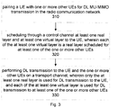
- An aspect of the present disclosure is a method of performing DL MU-MIMO transmission in a base station of a radio communication network enabling MU-MIMO.
- the method comprises: pairing a UE with one or more other UEs for DL MU-MIMO transmission in the radio communication network; scheduling through a control channel at least one real layer and at least one virtual layer to the UE, wherein each of the at least one virtual layer is a real layer scheduled for at least one of the one or more other UEs; and performing DL transmission to the UE and the one or more other UEs on a transport channel, wherein only the at least one real layer is used for DL transmission to the UE, and each of the at least one virtual layer is used for DL transmission to at least one of the one or more other UEs.
- the base station may comprise a pairing unit, a scheduling unit and a performing unit.
- the pairing unit is adapted to pair a UE with one or more other UEs for DL MU-MIMO transmission in the radio communication network;
- the scheduling unit is adapted to schedule through a control channel at least one real layer and at least one virtual layer to the UE, wherein each of the at least one virtual layer is a real layer scheduled for at least one of the one or more other UEs;
- the performing unit is adapted to perform DL transmission to the UE and the one or more other UEs on a transport channel, wherein only the at least one real layer is used for DL transmission to the UE, and each of the at least one virtual layer is used for DL transmission to at least one of the one or more other UEs.
- a further aspect of the present disclosure is a computer readable storage medium storing the instructions which, when running on a base station, cause the base station to perform the steps of the method as described above.
- Still a further aspect of the present disclosure is an apparatus for performing DL transmission in a radio communication network enabling MU-MIMO.
- the apparatus may comprise a processor and a memory.
- the memory contains instructions executable by the processor whereby the apparatus is operative to pair a UE with one or more other UEs for DL MU-MIMO transmission in the radio communication network; schedule through a control channel at least one real layer and at least one virtual layer to the UE, wherein each of the at least one virtual layer is a real layer scheduled for at least one of the one or more other UEs; and perform DL transmission to the UE and the one or more other UEs on a transport channel, wherein only the at least one real layer is used for DL transmission to the UE, and each of the at least one virtual layer is used for DL transmission to at least one of the one or more other UEs.
- the UE As a UE of the paired UEs is scheduled with both the real layer(s) used for DL transmission by itself and the virtual layer(s) actually used for such DL transmission by other paired UEs, the UE is implicitly triggered to perform joint detection among all the scheduled layers including both the real layer(s) and virtual layer(s), and meanwhile may be provided with supplementary information that may be used in the joint detection such as scrambling identity for reference signal, precoding matrix, number of layers, and the like.
- the interference from virtual layers i.e. the inter-layer interference from other paired UEs
- the performance gain of MU-MIMO over SU-MIMO can be readily obtained by further exploiting the spatial separation and diversity.
- the present technology may be embodied in hardware and/or in software (including firmware, resident software, micro-code, etc.).
- the present technology may take the form of a computer program on a computer-usable or computer-readable storage medium having computer-usable or computer-readable program code embodied in the medium for use by or in connection with an instruction execution system.
- a computer-usable or computer-readable storage medium may be any medium that may contain, store, or is adapted to communicate the program for use by or in connection with the instruction execution system, apparatus, or device.
- AP Access Point
- CN Core Network
- NodeB NodeB
- eNodeB eNodeB
- Fig.2 illustrates a schematic view of a DL MU-MIMO transmission in accordance with an embodiment in a radio communication network.
- the network 200 comprises a base station (BS) 210.
- the BS 210 serves UE 220 and UE 230.
- the network 200 may refer to any radio communication network enabling the MU-MIMO mechanism, including but not limited to the Time-Division Duplex Long-Term Evolution (TDD-LTE), Frequency-Division Duplex Long-Term Evolution (FDD-LTE), Time Division Synchronous Code Division Multiple Access (TD-SCDMA), Wireless Fidelity (WiFi), Bluetooth, Universal Mobile Telecommunications System (UMTS), Worldwide Interoperability for Microwave Access (WiMAX), and the like.
- TDD-LTE Time-Division Duplex Long-Term Evolution
- FDD-LTE Frequency-Division Duplex Long-Term Evolution
- TD-SCDMA Time Division Synchronous Code Division Multiple Access
- WiFi Wireless Fidelity
- Bluetooth Universal Mobile Telecommunications System
- UMTS Universal Mobile Telecommunications System
- WiMAX Worldwide Interoperability for Microwave Access
- base station used herein may indicate any type of communication node, such as Access Point (AP), macro base station, femto base station, Core Network (CN), NodeB, eNodeB etc.
- AP Access Point
- CN Core Network
- NodeB NodeB
- UE may indicates all forms of devices enabling the user to communicate via a radio communication network, such as, smart phones, cellular phone, Personal Digital Assistant (PDA), and the like.
- PDA Personal Digital Assistant
- each BS and two UEs are shown in the radio communication network 200. It will be appreciated that one or more BSs may exist in the wireless communication network, and each BS may serve one or more UEs in the mean time.
- FIG.3 shows a method of performing DL MU-MIMO transmission in accordance with an embodiment.
- the BS 210 pairs a UE (e.g. UE 220) with one or more other UEs (e.g. UE 230) for DL MU-MIMO transmission in a radio communication network e.g. network 200.
- the DL transmission refers to the data transmission from the BS to the UE(s).
- the term "paired UEs" will be used to represent two or more UEs sharing the same time-frequency resources, for example at different layers in space, in a DL MU-MIMO transmission.
- the paired UEs may include UE 220 and UE 230.
- more than one UE can be paired with a UE (e.g. UE 220 or 230) for the DL MU-MIMO transmission.
- the BS 210 may pair the UEs having a predetermined spatial distance from each other. However, it should be appreciated that the BS 210 may determine which UEs will be paired together for a DL MU-MIMO transmission depending on other known criteria.
- the BS 210 schedules at least one real layer and at least one virtual layer to the UE (e.g. UE220) through a control channel, e.g. the Physical Downlink Control Channel (PDCCH), and each of the at least one virtual layer is a real layer scheduled for at least one of the one or more other UEs (e.g. UE 230 in the scenario of Fig. 2 ).
- a real layer is defined as a layer that is scheduled through the control channel to a UE and used to perform DL transmission on the transport channel for the UE
- a virtual layer is defined as a layer that is scheduled through the control channel to a UE but without performing DL transmission on transport channel for the UE.
- the virtual layer is used to perform the DL transmission to other UE(s) whose real layer is such a virtual layer. As indicated, only part of layers scheduled to the UE will undertake the DL transmission to such UE.
- the BS 210 may schedule through the PDCCH the layer 1 and the layer 2 to the UE 220.
- the layer 1 is scheduled as the real layer of the UE 220 and the layer 2 is scheduled as the virtual layer of the UE 220.
- the BS 210 schedules the layer 2 to the UE 230.
- the layer 2 is scheduled as the real layer of the UE 230.
- the BS 210 may also schedule both the layer 1 and the layer 2 to the UE 230. In this case, the layer 2 still is the real layer of the UE 230 while the layer 1 is scheduled as the virtual layer of the UE 230.
- the BS 210 may allocate time-frequency resources for the scheduled layers including the real layer(s) and the virtual layer(s).
- the BS 210 will allocate PRB resources and modulation coding scheme (MCS) according to the UE 220's channel quality for the real layer of the UE 220 (i.e. layer 1) as that in conventional single-layer MU-MIMO, and meanwhile in order to enable the virtual layer of the UE 220 (i.e. layer 2), the BS 210 shall also set DL assignment information of corresponding transport blocks (TBs) in the Downlink Control Channel Information (DCI). Finally, the DCI will be transmitted through PDCCH to the UE 220.
- MCS modulation coding scheme
- a TB may include one or more layers.
- TB1 only includes the layer 1 and TB2 only includes the layer 2.
- TB1 represents the real layer while TB2 represents the virtual layer, but in UE 230, TB1 represents the virtual layer while TB2 represents the real layer.
- the virtual layers for a UE can be selected as desired. For example, provided that there are three UEs paired together, namely UE A, UE B and UE C, layer 1 is scheduled to UE A as its real layer, layer 2 is scheduled to UE B as its real layer, and layer 3 is scheduled to UE C as it real layer.
- the BS may schedule both layer 2 and layer 3 to the UE A as its virtual layers. Alternatively, the BS may only schedule layer 2 or layer 3 to the UE A as its virtual layer.
- one or more layers can be scheduled to a UE as its real layers.
- layer 1 and layer 2 can be scheduled to UE A as its real layers
- layer 3 can be scheduled to UE B as its real layer
- layer 3 is also scheduled to UE A as its virtual layer.
- neither the real layer nor the virtual layer is required to be dedicatedly scheduled to one UE. In other words, it is not necessary that all the time-frequency resources on a single layer will be scheduled to one UE. Two or more UEs may share the same layer, while being assigned different parts of the time-frequency resources on this layer.
- the BS 210 performs DL transmission to the UE (e.g. the UE 220) and the one or more other UEs (e.g. the UE 230) on a transport channel, e.g. Physical Downlink Shared Channel (PDSCH).
- a transport channel e.g. Physical Downlink Shared Channel (PDSCH).
- PDSCH Physical Downlink Shared Channel
- the UE 220 is scheduled with the layer 1 as its real layer and the layer 2 as its virtual layer
- the UE 230 is scheduled with the layer 2 as its real layer and the layer 1 as its virtual layer.
- the BS 210 will only enable the real layer of each UE for the DL transmission in a transport channel to the corresponding UE.
- only the layer 1 is used for the transmission to UE 220 by PDSCH
- only the layer 2 is used for transmission to the UE 230.
- the virtual layer granted on PDCCH is not really used for transmission for the corresponding UE on PDSCH.
- the TB2 corresponding to the layer 2 (the virtual layer of UE 220) is disabled, while for UE 230, the TB1 corresponding to the layer 1 (the virtual layer of UE 230) is disabled.
- the UE As a UE of the paired UEs is scheduled with both the real layer(s) used for DL transmission by itself and the virtual layer(s) actually used for such DL transmission by other paired UEs, the UE is implicitly triggered to perform joint detection among all the scheduled layers including both the real layer(s) and virtual layer(s), and meanwhile may be provided with supplementary information that may be used in the joint detection such as scrambling identity for reference signal, precoding matrix, number of layers, and the like.
- the interference from virtual layers i.e. the inter-layer interference from other paired UEs
- the performance gain of MU-MIMO over SU-MIMO can be readily obtained by further exploiting the spatial separation and diversity.
- some disadvantages caused by the conventional solutions can be obviated, such as the problem of computation complexity for null space processing.
- the virtual layer(s) scheduled to a UE won't be used to transmit the payload data of this UE, instead such virtual layers are used to transmit the payload data of other UE(s) (e.g. UE 230) paired with this UE, since the virtual layers of this UE are also scheduled to the other UE(s) as real layer(s).
- the UE 220 itself has no idea of the distinction between the real layer and the virtual layer scheduled to it, hence the UE 220 assumes that all the layers scheduled to it (including both the real layers and the virtual layers) will be used to transmit the payload data for it. In other words, the UE 220 takes all the scheduled layers as its real layers.
- the UE 220 will attempt to demodulate the data transmitted on both the real layer(s) and the virtual layer(s). As expected, it can demodulate the data on the real layer(s) successfully, but fails on the virtual layer(s). Because of the failures on the virtual layers, the UE 220 will report a hybrid automatic repeat request (HARQ) negative acknowledgement (NACK) to the BS 210. According to an embodiment, after receiving such HARQ NACK feedback from the UE 220, the BS 210 may simply ignore it. In this way, the whole DL transmission process can operate as usual in spite of the extra virtual layer scheduling.
- HARQ hybrid automatic repeat request
- NACK negative acknowledgement
- embodiments may be applicable to various networks with different antenna configurations such as 2Tx, 4Tx and 8Tx and transmission modes such as TM3, TM4, TM8 and TM9.
- the BS may firstly determine a codebook for the UE (e.g. UE 220) based on the number of layers scheduled for the UE and codebooks used in individual scheduled layers.
- the codebook for each of the real layers is used by the UE, and the codebook for each of the virtual layers is used by at least one of the one or more other UEs (e.g. UE 230).
- the BS 210 may inform the UE 220 of the codebook.
- the layer 1 is scheduled to the UE 220 as the real layer and scheduled to the UE 230 as the virtual layer
- the layer 2 is scheduled to the UE 230 as the real layer and scheduled to the UE 220 as the virtual layer.
- each layer will use a respective codebook in the DL transmission. Since only a single layer (layer 1) is used to perform the DL transmission to the UE 220, hence the BS 210 may assign the codebook 1 2 1 1 to be used on its real layer (layer 1) for the DL transmission, likewise the BS 210 may also assign the code book 1 2 1 ⁇ 1 to be used on the UE 230's real layer (layer 2) for the DL transmission.
- the BS 210 can merely inform the UE 220 of the codebook 1 2 1 1 used by the UE 220.
- the UE 220 is scheduled two layers, one real layer (layer 1) and one virtual layer (layer 2).
- the joint detection between the two scheduled layers involves the codebook (also referred to as precoding matrix) used on each layer.
- the BS 210 will find a codebook that combines the codebooks used on all the layers scheduled to the UE 220, i.e.
- the BS 210 may locate the codebook 1 2 1 1 1 ⁇ 1 as shown in the below table. Finally, the BS 210 informs the UE 220 of the codebook 1 2 1 1 1 ⁇ 1 instead of 1 2 1 1 .
- the gain and channel quality on layer 1 and layer 2 are usually imbalanced, which results in throughput degradation.
- the imbalance can be exploited. For instance, for UE 220, the gain on layer 1 is much higher than that on layer 2. While, for UE 230, the gain on layer 2 is much higher than that on layer 1. As a result, the gain from layer imbalance can be exploited.
- TM4 a transmission mode
- CRS common reference signal
- physical resource block allocations on all the layers scheduled for the UE are fully overlapped with each other.
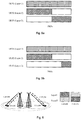
- the DL channel estimation is performed with the use of CRS and precoding matrix. It allows two or more UEs using the same precoding matrix to be paired together. In other words, the two or more UEs may share the same layer, while being assigned different parts of the PRB resources on this layer. In this case, the combined PRB allocations on each layer shall be strictly overlapped. As illustrated in Fig.
- the UE 51 occupies the PRB resources allocated on the layer 1, while the UE 52 and the UE 53 occupy different parts of the PRB resources allocated on the layer 2. But the whole PRB resources allocated on the layer 1 fully overlaps with the whole PRB resources allocated on the layer 2. That is, the PRB resources occupied by the UE 51 should be fully overlapped with the PRB resources occupied by the UE 52 plus those occupied by the UE 53.
- TM8 and TM9 DL channel estimation is based on UE-specific reference signal such as the demodulation reference signal (DMRS)
- DMRS demodulation reference signal
- the strict PRB overlapping as in TM4 may not be necessary. It's because that, in this case, the sequence of reference signal is independent on the scheduled PRB length.
- the reference signal on each PRB can be calculated by the UE according to the PRB position.
- the channel estimation can be done in granularity of one PRB.
- multiple UEs can be paired together with partial PRB overlapping as shown in Fig.5b .
- Such UE pairing is especially useful in case that the paired UEs have no equal amount of traffic in buffer to transmit.
- a same scrambling identity is allocated to all the paired UEs.
- the UE-specific reference signal sequence is generated according to cell ID and scrambling identity (n SCID ).
- the UE needs to perform the channel estimation for the virtual layer, if any, which involves the UE-specific reference signal sequence, and thus the UE needs to know the n SCID to calculate the UE-specific reference signal sequence.
- the UE will use a same n SCID to perform calculation for all the layers scheduled to it, including the real layer(s) and the virtual layer(s).
- the BS 210 allocates the same n SCID for all paired UEs, since the virtual layer of one UE has to be the real layer of another UE.
- LTE-TDD long-term evolution time division duplex
- SR physical service request
- ACK/NACK reported in the Physical Uplink Control Channel (PUCCH) is collided with the positive SR
- the spatial bundling will be applied at UE side.
- the ACK feedback for the real layer layer 1
- the NACK feedback for the virtual layer layer 2
- ACK &NACK the resulting feedback is NACK.
- the ACK feedback for the real layer is missing, which affects the HARQ feedback of the real layer.
- Such impact can be handled in the following ways:
- the idea of the present technology is applied in a combined cell.
- the paired UEs are located within a combined cell but in different cell areas of the combined cell, and use a transmission mode where DL channel estimation is based on CRS.
- cell 640 and cell 650 are combined as a combined cell.
- the UE 620 is covered by the cell 640 and the DL transmission is performed on layer 1
- the UE 630 is covered by the cell 650 and the DL transmission is performed on layer 2.
- the UE 620 and the UE 630 are within the same cell but in different cell areas, wherein one cell area (hereinafter referred to as cell area 1) is the area originally covered by cell 640 and the other cell area (hereinafter referred to as cell area 2) is the area originally covered by cell 650.
- cell area 1 one cell area
- cell area 2 is the area originally covered by cell 650.
- the UE 620 and the UE 630 may be paired for DL MU-MIMO transmission, and the UE 620 is scheduled with the layer 1 (i.e. the real layer of the UE 620) in DL transmission, while the UE 630 is scheduled with the layer 2 (i.e. the real layer of the UE 630) in the DL transmission.
- the DL inter-layer interference is inevitable between the UE 620 and the UE 630.
- the layer 2 is scheduled to the UE 620 as its virtual layer and/or the layer 1 is scheduled to the UE 630 as its virtual layer.
- the virtual layer scheduling may facilitate the removal/mitigation of the DL inter-layer interferences.
- the DL channel estimation is performed base on CRS.
- the CRS for each layer is broadcasted in all the areas of the combined cell including the cell area 1 and the cell area 2.
- the layer 1 is only used in the cell area 1 for DL transmission
- the layer 2 is only used in the cell area 2 for DL transmission.
- the transmission of CRS for the layer 1 to the cell area 2 may impact the channel estimation performed by the UE(s) in the cell area 2, and likewise, the transmission of CRS for the layer 2 to cell area 1 may impact the channel estimation performed by the UE(s) in the cell area 1.
- the CRS may only be transmitted to the cell area where the corresponding layer is really used for DL transmission to the UE(s) there. That is, CRS for the at least one real layer of a UE is only transmitted to the cell area where the UE is located. For example, the CRS for the layer 1 is only transmitted to the cell area 1, while the CRS for the layer 2 is only transmitted to the cell area 2.
- the embodiments may also be applicable to the combined cell where the channel estimation is based on DMRS, in which case such separate transmission of CRS as in the above described CRS-based combined cell is not necessary.
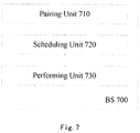
- Fig.7 is a block diagram of an exemplifying base station configured to perform the DL MI-MIMO transmission in accordance with an embodiment.
- the base station 700 may comprise a pairing unit 710, a scheduling unit 720 and a performing unit 730. It should be appreciated that the base station is not limited to the shown elements, and can comprise other conventional elements and additional elements for other purposes. Now the functions of the individual units will be described in detail with reference to the Fig.2 and Fig. 7 .
- the BS 700 in Fig.7 is taken as the BS 210 in the Fig.2 .
- the pairing unit 710 of the BS 700 is configured to pair a UE (e.g. UE 220) with one ore more other UEs (e.g. UE 230) for DL MU-MIMO transmission in a radio communication network, e.g. network 200.
- the DL transmission refers to the data transmission from the BS to the UE(s).
- the term "paired UEs" will be used to represent two or more UEs sharing the same time-frequency resources, for example at different layers in space, in a DL MU-MIMO transmission.
- the paired UEs may include UE 220 and UE 230.
- more than one UE can be paired with a UE (e.g. UE 220 or UE 230) for the DL MU-MIMO transmission.
- the pairing unit 710 may pair the UEs having a predetermined spatial distance from each other. However, it should be appreciated that the pairing unit 710 may determine which UEs will be paired together for a DL MU-MIMO transmission depending on other known criteria.
- the scheduling unit 720 of the BS 700 is configured to schedule at least one real layer and at least one virtual layer to the UE (e.g. UE 220) through a control channel, e.g. the Physical Downlink Control Channel (PDCCH), and each of the at least one virtual layer is a real layer scheduled for at least one of the one or more other UEs (e.g. UE 230 in the scenario of Fig.2 ).
- a real layer is defined as a layer that is scheduled through the control channel to a UE and used to perform DL transmission on the transport channel for the UE
- a virtual layers is defined as a layer that is scheduled through the control channel to a UE but without performing DL transmission on transport channel for the UE.
- the virtual layer is used to perform the DL transmission to other UE(s) whose real layer is such a virtual layer. As indicated, only part of layers scheduled to the UE will undertake the DL transmission to such UE.
- the scheduling unit 720 may schedule through the PDCCH the layer 1 and the layer 2 to the UE 220.
- the layer 1 is scheduled as the real layer of the UE 220 and the layer 2 is scheduled as the virtual layer of the UE 220.
- the scheduling unit 720 schedules the layer 2 to the UE 230.
- the layer 2 is scheduled as the real layer of the UE 230.
- the scheduling unit 720 may also schedule both the layer 1 and the layer 2 to the UE 230. In this case, the layer 2 still is the real layer of the UE 230 while the layer 1 is scheduled as the virtual layer of the UE 230.
- the scheduling unit 720 may allocate time-frequency resources for the scheduled layers including the real layer(s) and the virtual layer(s).
- the scheduling unit 720 will allocate PRB resources and MCS according to the UE 220's channel quality for the real layer of the UE 220 (i.e. layer 1) as that in conventional single-layer MU-MIMO, and meanwhile in order to enable the virtual layer of the UE 220 (i.e. layer 2), the scheduling unit 720 shall also set DL assignment information of corresponding transport blocks (TBs) in the DCI.
- the DCI will be transmitted through PDCCH to the UE 220.
- the UE 220 will assume both TB1 and TB2 enabled as illustrated in Fig.4a .
- a TB may include one or more layers.
- TB1 only includes the layer 1 and TB2 only includes the layer 2.
- TB 1 represents the real layer while TB2 represents the virtual layer, but in UE 230, TB1 represents the virtual layer while TB2 represents the real layer.
- the virtual layers for a UE can be selected as desired. For example, provided that there are three UEs paired together, namely UE A, UE B and UE C, layer 1 is scheduled to UE A as its real layer, layer 2 is scheduled to UE B as its real layer, and layer 3 is scheduled to UE C as it real layer.
- the scheduling unit 720 may schedule both layer 2 and layer 3 to the UE A as its virtual layers. Alternatively, the scheduling unit 720 may only schedule layer 2 or layer 3 to the UE A as its virtual layer.
- one or more layers can be scheduled to a UE as its real layers.
- layer 1 and layer 2 can be scheduled to UE A as its real layers
- layer 3 can be scheduled to UE B as its real layer
- layer 3 is also scheduled to UE A as its virtual layer.
- neither the real layer nor the virtual layer is required to be dedicatedly scheduled to one UE. In other words, it is not necessary that all the time-frequency resources on a single layer will be scheduled to one UE. Two or more UEs may share the same layer, while being assigned different parts of the time-frequency resources on this layer.
- the performing unit 730 of the BS 700 is configured to perform DL transmission to the UE (e.g. UE 220) and the one or more other UEs (e.g. UE 230) on a transport channel, e.g. Physical Downlink Shared Channel (PDSCH).
- a transport channel e.g. Physical Downlink Shared Channel (PDSCH).
- PDSCH Physical Downlink Shared Channel
- the UE 220 is scheduled with the layer 1 as its real layer and the layer 2 as its virtual layer
- the UE 230 is scheduled with the layer 2 as its real layer and the layer 1 as its virtual layer.
- the performing unit 730 will only enable the real layer of each UE for the DL transmission in a transport channel to the corresponding UE.
- only the layer 1 is used for the DL transmission to UE 220 by PDSCH
- only the layer 2 is used for the transmission to the UE 230.
- the virtual layer granted on PDCCH is not really used for transmission for the corresponding UE on PDSCH.
- the TB2 corresponding to the layer 2 (the virtual layer of UE 220) is disabled, while for UE 230, the TB1 corresponding to the layer 1 (the virtual layer of UE 230) is disabled.
- the UE As a UE of the paired UEs is scheduled with both the real layer(s) used for DL transmission by itself and the virtual layer(s) actually used for such DL transmission by other paired UEs, the UE is implicitly triggered to perform joint detection among all the scheduled layers including both the real layer(s) and virtual layer(s), and meanwhile may be provided with supplementary information that may be used in the joint detection such as scrambling identity for reference signal, precoding matrix, number of layers, and the like.
- the interference from virtual layers i.e. the inter-layer interference from other paired UEs
- the performance gain of MU-MIMO over SU-MIMO can be readily obtained by further exploiting the spatial separation and diversity.
- some disadvantages caused by the conventional solutions can be obviated, such as the problem of computation complexity for null space processing.
- the virtual layer(s) scheduled to a UE won't be used to transmit the payload data of this UE, instead such virtual layers are used to transmit the payload data of other UE(s) (e.g. UE 230) paired with this UE, since the virtual layer(s) of this UE are also scheduled to the other UE(s) as real layer(s).
- the UE 220 itself has no idea of the distinction between the real layer and the virtual layer scheduled to it, hence the UE 220 assumes that all the layers scheduled to it (including both the real layers and the virtual layers) will be used to transmit the payload data for it. In other words, the UE 220 takes all the scheduled layers as its real layers.
- the UE 220 will attempt to demodulate the data transmitted on both the real layer(s) and the virtual layer(s). As expected, it can demodulate the data on the real layer(s) successfully, but fails on the virtual layer(s). Because of the failures on the virtual layer(s), the UE 220 will report a hybrid automatic repeat request (HARQ) negative acknowledgement (NACK) to the BS 700. According to an embodiment, after receiving such HARQ NACK feedback from the UE 220, the BS 700 may simply ignore it. In this way, the whole DL transmission process can operate as usual in spite of the extra virtual layer scheduling.
- HARQ hybrid automatic repeat request
- NACK negative acknowledgement
- embodiments may be applicable to various networks with different antenna configurations such as 2Tx, 4Tx and 8Tx and transmission mode such as TM3, TM4, TM8 and TM9.
- the scheduling unit 720 may be further configured to firstly determine a codebook for the UE (e.g. UE 220) based on the number of layers scheduled for the UE and codebooks used in individual scheduled layers.
- the codebook for each of the real layers is used by the UE, and the codebook for each of the virtual layers is used by at least one of the one or more UEs (e.g. UE 230). Then the scheduling unit 720 may inform the UE 220 of the codebook.
- the layer 1 is scheduled to the UE 220 as the real layer and scheduled to the UE 230 as the virtual layer, while the layer 2 is scheduled to the UE 230 as the real layer and scheduled to the UE 220 as the virtual layer.
- each layer will use a respective codebook in the DL transmission. Since only a single layer (layer 1) is used to perform the DL transmission to the UE 220, hence the BS 700 (in particular the scheduling unit 720) may assign the codebook 1 2 1 1 to be used on its real layer (layer 1) for the DL transmission, likewise the BS 700 may also assign the code book 1 2 1 ⁇ 1 to be used on the UE 230's real layer (layer 2) for the DL transmission..
- the BS 700 can merely inform the UE 220 of the codebook 1 2 1 1 used by the UE 220.
- the UE 220 is scheduled two layers, one real layer (layer 1) and one virtual layer (layer 2).
- the joint detection between the two scheduled layers involves the codebook (also referred to as precoding matrix) used on each layer.
- the BS 700 will find a codebook that combines the codebooks used on all the layers scheduled to the UE 220, i.e.
- the BS 700 may locate the codebook 1 2 1 1 1 ⁇ 1 as shown in the below table. Finally, the BS 700 informs the UE 220 of the codebook 1 2 1 1 1 ⁇ 1 instead of 1 2 1 1 .
- the gain and channel quality on layer 1 and layer 2 are usually imbalanced, which results in throughput degradation.
- the imbalance can be exploited. For instance, for UE 220, the gain on layer 1 is much higher than that on layer 2. While, for UE 230, the gain on layer 2 is much higher than that on layer 1. As a result, the gain from layer imbalance can be exploited.
- TM4 a transmission mode
- CRS common reference signal
- physical resource block allocations on all the layers scheduled for the UE are fully overlapped with each other.
- the DL channel estimation is performed with the use of CRS and precoding matrix. It allows two or more UEs using the same precoding matrix to be paired together. In other words, the two or more UEs may share the same layer, while being assigned different parts of the PRB resources on this layer. In this case, the combined PRB allocations on each layer shall be strictly overlapped. As illustrated in Fig.
- the UE 51 occupies the PRB resources allocated on the layer 1, while the UE 52 and the UE 53 occupy different parts of the PRB resources allocated on the layer 2. But the whole PRB resources allocated on the layer 1 fully overlaps with the whole PRB resources allocated on the layer 2. That is, the PRB resources occupied by the UE 51 should be fully overlapped with the PRB resources occupied by the UE 52 plus those occupied by the UE 53.
- a transmission mode e.g. TM8 and TM9
- DL channel estimation is based on UE-specific reference signal such as the demodulation reference signal (DMRS)
- DMRS demodulation reference signal
- the strict PRB overlapping as in TM4 may not be necessary. It's because that, in this case, the sequence of reference signal is independent of the scheduled PRB length.
- the reference signal on each PRB can be calculated by the UE according to the PRB position.
- the channel estimation can be done in granularity of one PRB.
- multiple UEs can be paired together with partial PRB overlapping as shown in Fig.5b .
- Such UE pairing is especially useful in case that the paired UEs have no equal amount of traffic in buffer to transmit.
- a transmission mode e.g.
- TM8 and TM9 where DL channel estimation is based on UE-specific reference signal such as DMRS, a same scrambling identity is allocated to all the paired UEs. For example, In TM8 of Rel-9 and TM9 of Rel-10, the UE-specific reference signal sequence is generated according to cell ID and scrambling identity (n SCID ).
- the UE needs to perform the channel estimation for the virtual layer, if any, which involves the UE-specific reference signal sequence, and thus the UE needs to know the n SCID to calculate the UE-specific reference signal sequence.
- the UE will use a same n SCID to perform calculation for all the layers scheduled to it, including the real layer(s) and the virtual layer(s).
- the BS 700 allocates the same n SCID for all paired UEs since the virtual layer of one UE has to be the real layer of another UE.
- LTE-TDD long-term evolution time division duplex
- SR physical service request
- ACK/NACK reported in the Physical Uplink Control Channel (PUCCH) is collided with the positive SR
- the spatial bundling will be applied at UE side.
- the ACK feedback for the real layer layer 1
- the NACK feedback for the virtual layer layer 2
- ACK &NACK the resulting feedback is NACK.
- the ACK feedback for the real layer is missing, which affects the HARQ feedback of the real layer.
- Such impact can be handled in the following ways:
- the idea of the present technology is applied in a combined cell.
- the paired UEs are located within a combined cell but in different cell areas of the combined cell, and use a transmission mode where DL channel estimation is based on CRS.
- cell 640 and cell 650 are combined as a combined cell.
- the UE 620 is covered by the cell 640 and the DL transmission is performed on layer 1
- the UE 630 is covered by the cell 650 and the DL transmission is performed on layer 2.
- the UE 620 and the UE 630 are within the same cell but in different cell areas, wherein one cell area (hereinafter referred to as cell area 1) is the area originally covered by cell 640 and the other cell area (hereinafter referred to as cell area 2) is the area originally covered by cell 650.
- cell area 1 one cell area
- cell area 2 is the area originally covered by cell 650.
- the UE 620 and the UE 630 may be paired for DL MU-MIMO transmission, and the UE 620 is scheduled with the layer 1 (i.e. the real layer of the UE 620) in DL transmission, while the UE 630 is scheduled with the layer 2 (i.e. the real layer of the UE 630) in the DL transmission.
- the DL inter-layer interference is inevitable between the UE 620 and the UE 630.
- the layer 2 is scheduled to the UE 620 as its virtual layer and/or the layer 1 is scheduled to the UE 630 as its virtual layer.
- the virtual layer scheduling may facilitate the removal/mitigation of the DL inter-layer interferences.
- the DL channel estimation is performed base on CRS.
- the CRS for each layer is broadcasted in all the areas of the combined cell including the cell area 1 and the cell area 2.
- the layer 1 is only used in the cell area 1 for DL transmission
- the layer 2 is only used in the cell area 2 for DL transmission.
- the transmission of CRS for the layer 1 to the cell area 2 may impact the channel estimation performed by the UE(s) in the cell area 2, and likewise, the transmission of CRS for the layer 2 to cell area 1 may impact the channel estimation performed by the UE(s) in the cell area 1.
- the CRS may only be transmitted to the cell area where the corresponding layer is really used for DL transmission to the UE(s) there. That is, the BS may be configured to only transmit CRS for the at least one real layer of a UE to the cell area where the UE is located. For example, the CRS for the layer 1 is only transmitted to the cell area 1, while the CRS for the layer 2 is only transmitted to the cell area 2.
- the embodiments may also be applicable to the combined cell where the channel estimation is based on DMRS, in which case such separate transmission as in CRS-based combined cell is not necessary.
Landscapes
- Engineering & Computer Science (AREA)
- Signal Processing (AREA)
- Computer Networks & Wireless Communication (AREA)
- Physics & Mathematics (AREA)
- Mathematical Physics (AREA)
- Power Engineering (AREA)
- Mobile Radio Communication Systems (AREA)
- Radio Transmission System (AREA)
Claims (17)
- Übertragungsverfahren per Downlink, DL, in einer Basisstation (210) eines Funkkommunikationsnetzes (200), das eine Mehrfachbenutzer-Mehrfacheingabe-Mehrfachausgabe, MU-MIMO, ermöglicht, umfassend:Koppeln (310) einer Benutzereinrichtung, UE, mit einer oder mehreren anderen UEs für die DL-MU-MIMO-Übertragung in dem Funckommunikationsnetz;Planen (320) über einen Steuerkanal mindestens einer realen Schicht und mindestens einer virtuellen Schicht zur UE, wobei jede der mindestens einen virtuellen Schicht eine reale Schicht ist, die für mindestens eine der einen oder mehreren anderen UEs geplant ist, wobei die Planung der mindestens einen virtuellen Schicht durch den Steuerkanal erfolgt, ohne die DL-Übertragung in einem Transportkanal zur entsprechenden UE durchzuführen, und wobei die UE implizit ausgelöst wird, um eine gemeinsame Erkennung zwischen der mindestens einen realen Schicht und der mindestens einen virtuellen Schicht durchzuführen, wobei die gemeinsame Erkennung auf zusätzlichen Informationen basiert, einschließlich mindestens einer Verschlüsselung der Identität für das Referenzsignal, die Vorcodierungsmatrix und die Anzahl der Schichten; undDurchführen (330) einer DL-Übertragung zur UE und zu einer oder mehreren anderen UEs auf dem Transportkanal, wobei nur die mindestens eine reale Schicht für eine DL-Übertragung zur UE verwendet wird, und jede der mindestens einen virtuellen Schichten für eine DL-Übertragung zu mindestens einer der einen oder mehreren anderen UEs verwendet wird.
- Verfahren nach Anspruch 1, wobei, wenn eine codebuchbasierte Vorcodierung durch einen Übertragungsmodus des Netzes erforderlich ist, die Planung das Bestimmen eines Codebuchs für die UE basierend auf der Anzahl der für die UE geplanten Schichten und in einzelnen geplanten Schichten verwendete Codebücher, wobei das Codebuch für jede der mindestens einen realen Schicht von der UE verwendet wird und das Codebuch für jede der mindestens einen virtuellen Schichten von mindestens einer der einen oder mehreren anderen UEs verwendet wird, und das Informieren der UE über das Codebuch umfasst.
- Verfahren nach Anspruch 1, wobei in einem Übertragungsmodus, in dem die DL-Kanalschätzung auf einem gemeinsamen Referenzsignal, CRS, basiert, physische Ressourcenblockzuordnungen auf allen für die UE geplanten Schichten vollständig miteinander überlagert werden, und in einem Übertragungsmodus, in dem die DL-Kanalschätzung auf einem UE-spezifischen Referenzsignal basiert, physische Ressourcenblockzuordnungen auf allen für die UE geplanten Schichten teilweise miteinander überlagert werden dürfen.
- Verfahren nach Anspruch 1, wobei, wenn das Funkkommunikationsnetz (200) einen Mechanismus des Long-Term-Evolution-Zeitduplexes, LTE-TDD, verwendet, wobei das Verfahren ferner umfasst:wenn die Übertragung von Rückmeldungen zur hybriden automatischen Wiederholungsanforderung, HARQ, für die geplanten Schichten mit der Übertragung einer physischen Dienstanforderung, SR, kollidiert wird, die als HARQ-Rückmeldung eine räumlich gebündelte reale Schicht ACK und eine virtuelle Schicht NACK empfängt und die HARQ-Rückmeldung in einer Bestätigung, ACK, oder negativen Bestätigung, NACK, abbildet; oderwenn in einem Zeitfenster bestimmt wird, dass eine potenzielle Kollision zwischen der Übertragung der HARQ-Rückmeldung für zu planende Schichten und der Übertragung einer SR auftritt, wodurch die Planung der virtuellen Schicht an die UE in diesem Zeitfenster deaktiviert wird oder die DL-MU-MIMO-Übertragung in diesem Zeitfenster deaktiviert wird.
- Verfahren nach Anspruch 1, wobei in einem Übertragungsmodus, in dem die DL-Kanalschätzung auf einem UE-spezifischen Referenzsignal basiert, der UE und einer oder mehreren anderen UEs eine gleiche Verschlüsselungsidentität zugeordnet wird.
- Verfahren nach Anspruch 1, wobei, wenn sich die UE und die eine oder die mehreren anderen UEs innerhalb einer kombinierten Zelle, aber in verschiedenen Zellbereichen der kombinierten Zelle befinden und einen Übertragungsmodus verwenden, bei dem die DL-Kanalschätzung auf CRS basiert, das Verfahren ferner nur die Übertragung von CRS für die mindestens eine reale Schicht zu dem Zellbereich umfasst, in dem sich die UE befindet.
- Verfahren nach Anspruch 1, ferner umfassend beim Empfangen einer Rückmeldung zur negativen Bestätigung der hybriden automatischen Wiederholungsanforderung, HARQ NACK, für die mindestens eine virtuelle Schicht der UE, wobei die HARQ-NACK-Rückmeldung ignoriert wird.
- Verfahren nach einem der vorhergehenden Ansprüche, wobei das Funkkommunikationsnetz ein Netz der Zeitduplex-Long-Term-Evolution, TDD-LTE, oder ein Netz der Frequenzduplex-Long-Term-Evolution, FDD-LTE, ist.
- Basisstation (700), die so konfiguriert ist, dass sie eine Übertragung per Downlink, DL, in einem Funkkommunikationsnetz (200) durchführt, das eine Mehrfachbenutzer-Mehrfacheingabe-Mehrfachausgabe, MU-MIMO, ermöglicht, umfassend:eine Kopplungseinheit (710), die angepasst ist, um eine Benutzervorrichtung, UE, mit einer oder mehreren anderen UEs für die DL-MU-MIMO-Übertragung in dem Funkkommunikationsnetz zu koppeln;eine Planungseinheit (720), die angepasst ist, um über einen Steuerkanal mindestens eine reale Schicht und mindestens eine virtuelle Schicht zur UE zu planen, wobei jede der mindestens einen virtuellen Schicht eine reale Schicht ist, die für mindestens eine der einen oder mehreren anderen UEs geplant ist, wobei die Planung der mindestens einen virtuellen Schicht durch den Steuerkanal erfolgt, ohne die DL-Übertragung in einem Transportkanal zur entsprechenden UE durchzuführen, und wobei die UE implizit ausgelöst wird, um eine gemeinsame Erkennung zwischen der mindestens einen realen Schicht und der mindestens einen virtuellen Schicht durchzuführen, wobei die gemeinsame Erkennung auf zusätzlichen Informationen basiert, einschließlich mindestens einer Verschlüsselung der Identität für das Referenzsignal, die Vorcodierungsmatrix und die Anzahl der Schichten; undeine Durchführeinheit (730), die angepasst ist, um eine DL-Übertragung zur UE und zu einer oder mehreren anderen UEs auf einem Transportkanal durchzuführen, wobei nur die mindestens eine reale Schicht für eine DL-Übertragung zur UE verwendet wird, und jede der mindestens einen virtuellen Schichten für eine DL-Übertragung zu mindestens einer der einen oder mehreren anderen UEs verwendet wird.
- Basisstation (700) nach Anspruch 9, wobei, wenn eine codebuchbasierte Vorcodierung durch einen Übertragungsmodus des Netzes erforderlich ist, die Planungseinheit so angepasst ist, um ein Codebuch für die UE basierend auf der Anzahl der für die UE geplanten Schichten und in einzelnen geplanten Schichten verwendete Codebücher zu bestimmen, wobei das Codebuch für jede der mindestens einen realen Schichten von der UE verwendet wird und das Codebuch für jede der mindestens einen virtuellen Schichten von mindestens einer der einen oder mehreren anderen UEs verwendet wird, und um die UE über das Codebuch zu informieren.
- Basisstation (700) nach Anspruch 9, wobei in einem Übertragungsmodus, in dem die DL-Kanalschätzung auf einem gemeinsamen Referenzsignal, CRS, basiert, physische Ressourcenblockzuordnungen auf allen für die UE geplanten Schichten vollständig miteinander überlagert werden, und in einem Übertragungsmodus, in dem die DL-Kanalschätzung auf einem UE-spezifischen Referenzsignal basiert, physische Ressourcenblockzuordnungen auf allen für die UE geplanten Schichten teilweise miteinander überlagert werden dürfen.
- Basisstation (700) nach Anspruch 9, wobei, wenn das Funkkommunikationsnetz einen Mechanismus des Long-Term-Evolution-Zeitduplexes, LTE-TDD, verwendet, wobei:wenn die Übertragung von Rückmeldungen zur hybriden automatischen Wiederholungsanforderung, HARQ, für die geplanten Schichten mit der Übertragung einer physischen Dienstanforderung, SR, kollidiert wird, die Basisstation so angepasst ist, um als HARQ-Rückmeldung eine räumlich gebündelte reale Schicht ACK und eine virtuelle Schicht NACK zu empfangen und die HARQ-Rückmeldung in einer Bestätigung, ACK, oder negativen Bestätigung, NACK, abzubilden; oderwenn in einem Zeitfenster bestimmt wird, dass eine potenzielle Kollision zwischen der Übertragung der HARQ-Rückmeldung für zu planende Schichten und der Übertragung einer SR auftritt, die Basisstation so angepasst ist, um die Planung der virtuellen Schicht an die UE in diesem Zeitfenster zu deaktivieren oder die DL-MU-MIMO-Übertragung in diesem Zeitfenster zu deaktivieren.
- Basisstation (700) nach Anspruch 9, wobei in einem Übertragungsmodus, in dem die DL-Kanalschätzung auf einem UE-spezifischen Referenzsignal basiert, der UE und einer oder mehreren anderen UEs eine gleiche Verschlüsselungsidentität zugeordnet wird.
- Basisstation (700) nach Anspruch 9, wobei, wenn sich die UE und die eine oder die mehreren anderen UEs innerhalb einer kombinierten Zelle, aber in verschiedenen Zellbereichen der kombinierten Zelle befinden und einen Übertragungsmodus verwenden, bei dem die DL-Kanalschätzung auf CRS basiert, die Basisstation angepasst ist, um nur CRS für die mindestens eine reale Schicht zu dem Zellbereich, in dem sich die UE befindet, zu übertragen.
- Basisstation (700) nach Anspruch 9, wobei beim Empfangen einer Rückmeldung zur negativen Bestätigung der hybriden automatischen Wiederholungsanforderung, HARQ-NACK, für die mindestens eine virtuelle Schicht der UE, die Basisstation angepasst ist, um die HARQ-NACK-Rückmeldung zu ignorieren.
- Computerlesbares Speichermedium, das Befehle speichert, die, wenn sie auf einer Basisstation ausgeführt werden, bewirken, dass die Basisstation die Schritte des Verfahrens nach jedem der Ansprüche 1-8 durchführt.
- Vorrichtung zur Durchführung einer Übertragung per Downlink, DL, in einem Funkkommunikationsnetz, das eine Mehrfachbenutzer-Mehrfacheingabe-Mehrfachausgabe, MU-MIMO, ermöglicht, umfassend einen Prozessor und einen Speicher, wobei der Speicher Anweisungen enthält, die durch den Prozessor ausführbar sind, wodurch die Vorrichtung betrieben werden kann zum:Koppeln einer Benutzereinrichtung, UE, mit einer oder mehreren anderen UEs für die DL-MU-MIMO-Übertragung in dem Funkkommunikationsnetz;Planen, über einen Steuerkanal, mindestens einer realen Schicht und mindestens einer virtuellen Schicht zur UE, wobei jede der mindestens einen virtuellen Schicht eine reale Schicht ist, die für mindestens eine der einen oder mehreren anderen UEs geplant ist, wobei die Planung der mindestens einen virtuellen Schicht durch den Steuerkanal erfolgt, ohne die DL-Übertragung in einem Transportkanal zur entsprechenden UE durchzuführen, und wobei die UE implizit ausgelöst wird, um eine gemeinsame Erkennung zwischen der mindestens einen realen Schicht und der mindestens einen virtuellen Schicht durchzuführen, wobei die gemeinsame Erkennung auf zusätzlichen Informationen basiert, einschließlich mindestens einer Verschlüsselung der Identität für das Referenzsignal, die Vorcodierungsmatrix und die Anzahl der Schichten; undDurchführen von DL-Übertragung zur UE und zu einer oder mehreren anderen UEs auf einem Transportkanal, wobei nur die mindestens eine reale Schicht für eine DL-Übertragung zur UE verwendet wird, und jede der mindestens einen virtuellen Schichten für eine DL-Übertragung zu mindestens einer der einen oder mehreren anderen UEs verwendet wird.
Applications Claiming Priority (1)
| Application Number | Priority Date | Filing Date | Title |
|---|---|---|---|
| PCT/CN2013/082045 WO2015024227A1 (en) | 2013-08-22 | 2013-08-22 | Method and apparatus for performing downlink mu-mimo transmission |
Publications (3)
| Publication Number | Publication Date |
|---|---|
| EP3036952A1 EP3036952A1 (de) | 2016-06-29 |
| EP3036952A4 EP3036952A4 (de) | 2017-04-19 |
| EP3036952B1 true EP3036952B1 (de) | 2019-10-09 |
Family
ID=52482963
Family Applications (1)
| Application Number | Title | Priority Date | Filing Date |
|---|---|---|---|
| EP13891675.4A Active EP3036952B1 (de) | 2013-08-22 | 2013-08-22 | Verfahren und vorrichtung zur durchführung einer downlink-mu-mimo-übertragung |
Country Status (4)
| Country | Link |
|---|---|
| US (1) | US9888491B2 (de) |
| EP (1) | EP3036952B1 (de) |
| CN (1) | CN105684534B (de) |
| WO (1) | WO2015024227A1 (de) |
Families Citing this family (11)
| Publication number | Priority date | Publication date | Assignee | Title |
|---|---|---|---|---|
| CN104144030B (zh) * | 2013-05-09 | 2019-05-10 | 中兴通讯股份有限公司 | 数据发送、接收方法、数据发送及接收端 |
| CN104683079B (zh) * | 2013-11-26 | 2018-05-11 | 深圳市海思半导体有限公司 | 传输模式切换方法及设备 |
| WO2015133812A1 (ko) * | 2014-03-04 | 2015-09-11 | 엘지전자 주식회사 | 다중 안테나 무선 통신 시스템에서 향상된 참조 신호 송신 방법 및 이를 위한 장치 |
| WO2015141266A1 (ja) * | 2014-03-20 | 2015-09-24 | シャープ株式会社 | 端末装置、基地局装置、および集積回路 |
| CN111770038A (zh) * | 2014-12-16 | 2020-10-13 | 富士通株式会社 | 下行信道估计方法、装置、通信系统以及终端 |
| US10063292B2 (en) * | 2015-02-02 | 2018-08-28 | Qualcomm Incorporated | Multi-user operation management |
| CN106488562A (zh) * | 2015-08-31 | 2017-03-08 | 北京信威通信技术股份有限公司 | 用于传输多用户mimo控制信息的装置和系统 |
| CN106488573A (zh) * | 2015-08-31 | 2017-03-08 | 北京信威通信技术股份有限公司 | 叠加编码的多用户mimo的控制信息发送和接收方法 |
| CN106488572A (zh) * | 2015-08-31 | 2017-03-08 | 北京信威通信技术股份有限公司 | 叠加编码的多用户mimo的控制信息发送和接收方法 |
| EP3340715A4 (de) * | 2015-09-24 | 2018-08-22 | Huawei Technologies Co., Ltd. | Downlink-steuersignalisierungsübertragungsverfahren und -vorrichtung |
| CN110830174B (zh) * | 2018-08-10 | 2020-11-27 | 北京紫光展锐通信技术有限公司 | 半静态harq-ack码本的生成方法、用户终端、可读存储介质 |
Citations (1)
| Publication number | Priority date | Publication date | Assignee | Title |
|---|---|---|---|---|
| WO2012161082A1 (ja) * | 2011-05-20 | 2012-11-29 | 株式会社エヌ・ティ・ティ・ドコモ | 受信装置、送信装置及び無線通信方法 |
Family Cites Families (11)
| Publication number | Priority date | Publication date | Assignee | Title |
|---|---|---|---|---|
| KR101274663B1 (ko) | 2008-06-30 | 2013-06-17 | 노키아 지멘스 네트웍스 오와이 | 일반 및 가상 듀얼 계층 ack/nack 사이의 선택 |
| US20120026964A1 (en) * | 2009-03-27 | 2012-02-02 | Nokia Corporation | System and method for signaling of interfering spatial layers with dedicated reference signal |
| CN101854668A (zh) | 2009-04-03 | 2010-10-06 | 大唐移动通信设备有限公司 | 一种mu-mimo中的数据传输方法、系统及装置 |
| KR101478316B1 (ko) | 2009-04-28 | 2014-12-31 | 한국전자통신연구원 | 전용 레퍼런스 시그널 전송 방법 및 전용 레퍼런스 시그널 수신 방법 |
| US8797950B2 (en) * | 2009-05-27 | 2014-08-05 | Texas Instruments Incorporated | Dual-layer beam forming in cellular networks |
| US9264097B2 (en) * | 2009-06-04 | 2016-02-16 | Qualcomm Incorporated | Interference mitigation for downlink in a wireless communication system |
| US8711716B2 (en) * | 2009-06-19 | 2014-04-29 | Texas Instruments Incorporated | Multiple CQI feedback for cellular networks |
| US8750205B2 (en) * | 2009-08-07 | 2014-06-10 | Texas Instruments Incorporated | Multiple rank CQI feedback for cellular networks |
| US8406332B2 (en) * | 2010-01-18 | 2013-03-26 | Research In Motion Limited | Downlink transmission in a multiple-user multiple-input multiple-output (“MU-MIMO”) wireless communication system |
| TW201728104A (zh) * | 2011-08-12 | 2017-08-01 | 內數位專利控股公司 | 多書入多輸出操作方法及裝置 |
| CN102740480B (zh) | 2012-06-14 | 2014-11-19 | 大唐移动通信设备有限公司 | 一种配对用户的干扰抑制方法及装置 |
-
2013
- 2013-08-22 CN CN201380079027.8A patent/CN105684534B/zh active Active
- 2013-08-22 WO PCT/CN2013/082045 patent/WO2015024227A1/en active Application Filing
- 2013-08-22 US US14/909,868 patent/US9888491B2/en active Active
- 2013-08-22 EP EP13891675.4A patent/EP3036952B1/de active Active
Patent Citations (2)
| Publication number | Priority date | Publication date | Assignee | Title |
|---|---|---|---|---|
| WO2012161082A1 (ja) * | 2011-05-20 | 2012-11-29 | 株式会社エヌ・ティ・ティ・ドコモ | 受信装置、送信装置及び無線通信方法 |
| US20140050279A1 (en) * | 2011-05-20 | 2014-02-20 | Ntt Docomo, Inc. | Receiver, transmitter and radio communication method |
Non-Patent Citations (1)
| Title |
|---|
| SHUN TOMIDA ET AL: "Non-orthogonal access with SIC in cellular downlink for user fairness enhancement", INTELLIGENT SIGNAL PROCESSING AND COMMUNICATIONS SYSTEMS (ISPACS), 2011 INTERNATIONAL SYMPOSIUM ON, IEEE, 7 December 2011 (2011-12-07), pages 1 - 6, XP032114760, ISBN: 978-1-4577-2165-6, DOI: 10.1109/ISPACS.2011.6146188 * |
Also Published As
| Publication number | Publication date |
|---|---|
| US20160183289A1 (en) | 2016-06-23 |
| CN105684534B (zh) | 2020-03-17 |
| US9888491B2 (en) | 2018-02-06 |
| EP3036952A4 (de) | 2017-04-19 |
| CN105684534A (zh) | 2016-06-15 |
| EP3036952A1 (de) | 2016-06-29 |
| WO2015024227A1 (en) | 2015-02-26 |
Similar Documents
| Publication | Publication Date | Title |
|---|---|---|
| EP3036952B1 (de) | Verfahren und vorrichtung zur durchführung einer downlink-mu-mimo-übertragung | |
| US9948437B2 (en) | Method and apparatus for inter-cell interference coordination in a wireless communication system | |
| US9509390B2 (en) | Method and apparatus for providing Channel State Information-Reference Signal (CSI-RS) configuration information in a wireless communication system supporting multiple antennas | |
| US9264204B2 (en) | Method and apparatus for inter-cell interference coordination for transmission point group | |
| US9276662B2 (en) | Method and apparatus for handing over mobile cell | |
| EP3051741B1 (de) | Verbesserte verbindungsanpassung | |
| US10148379B2 (en) | Method for transmitting network assistance information for removing interference and serving cell base station | |
| US20140301332A1 (en) | Method and device for inter cell interference coordination in wireless communication system | |
| US20170064721A1 (en) | Method and apparatus for allocating resources in wireless access system supporting fdr transmission | |
| US20140133336A1 (en) | Channel state information transmitting method and user equipment, and channel state information receiving method and base station | |
| US10651988B2 (en) | Method and device for selecting multiple users and allocating resources for non-orthogonal multiple access in wireless communication system | |
| US9496929B2 (en) | Coordinated beamforming method in wireless access system, and apparatus therefor | |
| US10103831B2 (en) | Method for transmitting and receiving signal in wireless communication system and apparatus for performing same | |
| US9768940B2 (en) | Method and device for transmitting and receiving signal in multi-cell cooperative communication system | |
| US9300502B2 (en) | Method and device for performing coordinated precoding in wireless access system | |
| US20170273091A1 (en) | Method and device for receiving signal in wireless access system supporting fdr transmission | |
| EP3179647B1 (de) | Verfahren und vorrichtung zum empfangen eines signals in einem drahtloszugangssystem mit unterstützung von fdr-übertragung | |
| US11329778B2 (en) | Resource allocation method and apparatus, and signal transmission method | |
| CN110999350A (zh) | 无线通信方法和网络节点 |
Legal Events
| Date | Code | Title | Description |
|---|---|---|---|
| PUAI | Public reference made under article 153(3) epc to a published international application that has entered the european phase |
Free format text: ORIGINAL CODE: 0009012 |
|
| 17P | Request for examination filed |
Effective date: 20160301 |
|
| AK | Designated contracting states |
Kind code of ref document: A1 Designated state(s): AL AT BE BG CH CY CZ DE DK EE ES FI FR GB GR HR HU IE IS IT LI LT LU LV MC MK MT NL NO PL PT RO RS SE SI SK SM TR |
|
| AX | Request for extension of the european patent |
Extension state: BA ME |
|
| DAX | Request for extension of the european patent (deleted) | ||
| A4 | Supplementary search report drawn up and despatched |
Effective date: 20170317 |
|
| RIC1 | Information provided on ipc code assigned before grant |
Ipc: H04B 7/0456 20170101ALI20170313BHEP Ipc: H04J 11/00 20060101ALI20170313BHEP Ipc: H04W 72/00 20090101AFI20170313BHEP Ipc: H04B 7/0452 20170101ALI20170313BHEP |
|
| RIC1 | Information provided on ipc code assigned before grant |
Ipc: H04B 7/0456 20170101ALI20170313BHEP Ipc: H04B 7/0452 20170101ALI20170313BHEP Ipc: H04W 72/00 20090101AFI20170313BHEP Ipc: H04J 11/00 20060101ALI20170313BHEP |
|
| STAA | Information on the status of an ep patent application or granted ep patent |
Free format text: STATUS: EXAMINATION IS IN PROGRESS |
|
| RIC1 | Information provided on ipc code assigned before grant |
Ipc: H04J 11/00 20060101ALI20170313BHEP Ipc: H04B 7/0452 20170101ALI20170313BHEP Ipc: H04B 7/0456 20170101ALI20170313BHEP Ipc: H04W 72/00 20090101AFI20170313BHEP |
|
| 17Q | First examination report despatched |
Effective date: 20190212 |
|
| REG | Reference to a national code |
Ref country code: DE Ref legal event code: R079 Ref document number: 602013061659 Country of ref document: DE Free format text: PREVIOUS MAIN CLASS: H04W0072000000 Ipc: H04B0007045200 |
|
| GRAP | Despatch of communication of intention to grant a patent |
Free format text: ORIGINAL CODE: EPIDOSNIGR1 |
|
| STAA | Information on the status of an ep patent application or granted ep patent |
Free format text: STATUS: GRANT OF PATENT IS INTENDED |
|
| RIC1 | Information provided on ipc code assigned before grant |
Ipc: H04W 72/12 20090101ALI20190725BHEP Ipc: H04L 25/03 20060101ALI20190725BHEP Ipc: H04L 25/02 20060101ALN20190725BHEP Ipc: H04L 1/16 20060101ALI20190725BHEP Ipc: H04J 11/00 20060101ALI20190725BHEP Ipc: H04B 7/0456 20170101ALI20190725BHEP Ipc: H04B 7/0452 20170101AFI20190725BHEP |
|
| GRAS | Grant fee paid |
Free format text: ORIGINAL CODE: EPIDOSNIGR3 |
|
| GRAA | (expected) grant |
Free format text: ORIGINAL CODE: 0009210 |
|
| STAA | Information on the status of an ep patent application or granted ep patent |
Free format text: STATUS: THE PATENT HAS BEEN GRANTED |
|
| INTG | Intention to grant announced |
Effective date: 20190812 |
|
| AK | Designated contracting states |
Kind code of ref document: B1 Designated state(s): AL AT BE BG CH CY CZ DE DK EE ES FI FR GB GR HR HU IE IS IT LI LT LU LV MC MK MT NL NO PL PT RO RS SE SI SK SM TR |
|
| REG | Reference to a national code |
Ref country code: GB Ref legal event code: FG4D |
|
| REG | Reference to a national code |
Ref country code: CH Ref legal event code: EP |
|
| REG | Reference to a national code |
Ref country code: IE Ref legal event code: FG4D |
|
| REG | Reference to a national code |
Ref country code: DE Ref legal event code: R096 Ref document number: 602013061659 Country of ref document: DE |
|
| REG | Reference to a national code |
Ref country code: AT Ref legal event code: REF Ref document number: 1190025 Country of ref document: AT Kind code of ref document: T Effective date: 20191115 |
|
| REG | Reference to a national code |
Ref country code: NL Ref legal event code: MP Effective date: 20191009 |
|
| REG | Reference to a national code |
Ref country code: LT Ref legal event code: MG4D |
|
| REG | Reference to a national code |
Ref country code: AT Ref legal event code: MK05 Ref document number: 1190025 Country of ref document: AT Kind code of ref document: T Effective date: 20191009 |
|
| PG25 | Lapsed in a contracting state [announced via postgrant information from national office to epo] |
Ref country code: GR Free format text: LAPSE BECAUSE OF FAILURE TO SUBMIT A TRANSLATION OF THE DESCRIPTION OR TO PAY THE FEE WITHIN THE PRESCRIBED TIME-LIMIT Effective date: 20200110 Ref country code: ES Free format text: LAPSE BECAUSE OF FAILURE TO SUBMIT A TRANSLATION OF THE DESCRIPTION OR TO PAY THE FEE WITHIN THE PRESCRIBED TIME-LIMIT Effective date: 20191009 Ref country code: PT Free format text: LAPSE BECAUSE OF FAILURE TO SUBMIT A TRANSLATION OF THE DESCRIPTION OR TO PAY THE FEE WITHIN THE PRESCRIBED TIME-LIMIT Effective date: 20200210 Ref country code: AT Free format text: LAPSE BECAUSE OF FAILURE TO SUBMIT A TRANSLATION OF THE DESCRIPTION OR TO PAY THE FEE WITHIN THE PRESCRIBED TIME-LIMIT Effective date: 20191009 Ref country code: NL Free format text: LAPSE BECAUSE OF FAILURE TO SUBMIT A TRANSLATION OF THE DESCRIPTION OR TO PAY THE FEE WITHIN THE PRESCRIBED TIME-LIMIT Effective date: 20191009 Ref country code: PL Free format text: LAPSE BECAUSE OF FAILURE TO SUBMIT A TRANSLATION OF THE DESCRIPTION OR TO PAY THE FEE WITHIN THE PRESCRIBED TIME-LIMIT Effective date: 20191009 Ref country code: LT Free format text: LAPSE BECAUSE OF FAILURE TO SUBMIT A TRANSLATION OF THE DESCRIPTION OR TO PAY THE FEE WITHIN THE PRESCRIBED TIME-LIMIT Effective date: 20191009 Ref country code: BG Free format text: LAPSE BECAUSE OF FAILURE TO SUBMIT A TRANSLATION OF THE DESCRIPTION OR TO PAY THE FEE WITHIN THE PRESCRIBED TIME-LIMIT Effective date: 20200109 Ref country code: FI Free format text: LAPSE BECAUSE OF FAILURE TO SUBMIT A TRANSLATION OF THE DESCRIPTION OR TO PAY THE FEE WITHIN THE PRESCRIBED TIME-LIMIT Effective date: 20191009 Ref country code: LV Free format text: LAPSE BECAUSE OF FAILURE TO SUBMIT A TRANSLATION OF THE DESCRIPTION OR TO PAY THE FEE WITHIN THE PRESCRIBED TIME-LIMIT Effective date: 20191009 Ref country code: SE Free format text: LAPSE BECAUSE OF FAILURE TO SUBMIT A TRANSLATION OF THE DESCRIPTION OR TO PAY THE FEE WITHIN THE PRESCRIBED TIME-LIMIT Effective date: 20191009 Ref country code: NO Free format text: LAPSE BECAUSE OF FAILURE TO SUBMIT A TRANSLATION OF THE DESCRIPTION OR TO PAY THE FEE WITHIN THE PRESCRIBED TIME-LIMIT Effective date: 20200109 |
|
| PG25 | Lapsed in a contracting state [announced via postgrant information from national office to epo] |
Ref country code: RS Free format text: LAPSE BECAUSE OF FAILURE TO SUBMIT A TRANSLATION OF THE DESCRIPTION OR TO PAY THE FEE WITHIN THE PRESCRIBED TIME-LIMIT Effective date: 20191009 Ref country code: HR Free format text: LAPSE BECAUSE OF FAILURE TO SUBMIT A TRANSLATION OF THE DESCRIPTION OR TO PAY THE FEE WITHIN THE PRESCRIBED TIME-LIMIT Effective date: 20191009 Ref country code: IS Free format text: LAPSE BECAUSE OF FAILURE TO SUBMIT A TRANSLATION OF THE DESCRIPTION OR TO PAY THE FEE WITHIN THE PRESCRIBED TIME-LIMIT Effective date: 20200224 |
|
| PG25 | Lapsed in a contracting state [announced via postgrant information from national office to epo] |
Ref country code: AL Free format text: LAPSE BECAUSE OF FAILURE TO SUBMIT A TRANSLATION OF THE DESCRIPTION OR TO PAY THE FEE WITHIN THE PRESCRIBED TIME-LIMIT Effective date: 20191009 |
|
| REG | Reference to a national code |
Ref country code: DE Ref legal event code: R097 Ref document number: 602013061659 Country of ref document: DE |
|
| PG2D | Information on lapse in contracting state deleted |
Ref country code: IS |
|
| PG25 | Lapsed in a contracting state [announced via postgrant information from national office to epo] |
Ref country code: EE Free format text: LAPSE BECAUSE OF FAILURE TO SUBMIT A TRANSLATION OF THE DESCRIPTION OR TO PAY THE FEE WITHIN THE PRESCRIBED TIME-LIMIT Effective date: 20191009 Ref country code: RO Free format text: LAPSE BECAUSE OF FAILURE TO SUBMIT A TRANSLATION OF THE DESCRIPTION OR TO PAY THE FEE WITHIN THE PRESCRIBED TIME-LIMIT Effective date: 20191009 Ref country code: CZ Free format text: LAPSE BECAUSE OF FAILURE TO SUBMIT A TRANSLATION OF THE DESCRIPTION OR TO PAY THE FEE WITHIN THE PRESCRIBED TIME-LIMIT Effective date: 20191009 Ref country code: DK Free format text: LAPSE BECAUSE OF FAILURE TO SUBMIT A TRANSLATION OF THE DESCRIPTION OR TO PAY THE FEE WITHIN THE PRESCRIBED TIME-LIMIT Effective date: 20191009 Ref country code: IS Free format text: LAPSE BECAUSE OF FAILURE TO SUBMIT A TRANSLATION OF THE DESCRIPTION OR TO PAY THE FEE WITHIN THE PRESCRIBED TIME-LIMIT Effective date: 20200209 |
|
| PLBE | No opposition filed within time limit |
Free format text: ORIGINAL CODE: 0009261 |
|
| STAA | Information on the status of an ep patent application or granted ep patent |
Free format text: STATUS: NO OPPOSITION FILED WITHIN TIME LIMIT |
|
| PG25 | Lapsed in a contracting state [announced via postgrant information from national office to epo] |
Ref country code: SK Free format text: LAPSE BECAUSE OF FAILURE TO SUBMIT A TRANSLATION OF THE DESCRIPTION OR TO PAY THE FEE WITHIN THE PRESCRIBED TIME-LIMIT Effective date: 20191009 Ref country code: IT Free format text: LAPSE BECAUSE OF FAILURE TO SUBMIT A TRANSLATION OF THE DESCRIPTION OR TO PAY THE FEE WITHIN THE PRESCRIBED TIME-LIMIT Effective date: 20191009 Ref country code: SM Free format text: LAPSE BECAUSE OF FAILURE TO SUBMIT A TRANSLATION OF THE DESCRIPTION OR TO PAY THE FEE WITHIN THE PRESCRIBED TIME-LIMIT Effective date: 20191009 |
|
| 26N | No opposition filed |
Effective date: 20200710 |
|
| PG25 | Lapsed in a contracting state [announced via postgrant information from national office to epo] |
Ref country code: SI Free format text: LAPSE BECAUSE OF FAILURE TO SUBMIT A TRANSLATION OF THE DESCRIPTION OR TO PAY THE FEE WITHIN THE PRESCRIBED TIME-LIMIT Effective date: 20191009 |
|
| PG25 | Lapsed in a contracting state [announced via postgrant information from national office to epo] |
Ref country code: MC Free format text: LAPSE BECAUSE OF FAILURE TO SUBMIT A TRANSLATION OF THE DESCRIPTION OR TO PAY THE FEE WITHIN THE PRESCRIBED TIME-LIMIT Effective date: 20191009 |
|
| REG | Reference to a national code |
Ref country code: CH Ref legal event code: PL |
|
| PG25 | Lapsed in a contracting state [announced via postgrant information from national office to epo] |
Ref country code: CH Free format text: LAPSE BECAUSE OF NON-PAYMENT OF DUE FEES Effective date: 20200831 Ref country code: LI Free format text: LAPSE BECAUSE OF NON-PAYMENT OF DUE FEES Effective date: 20200831 Ref country code: LU Free format text: LAPSE BECAUSE OF NON-PAYMENT OF DUE FEES Effective date: 20200822 |
|
| REG | Reference to a national code |
Ref country code: BE Ref legal event code: MM Effective date: 20200831 |
|
| PG25 | Lapsed in a contracting state [announced via postgrant information from national office to epo] |
Ref country code: FR Free format text: LAPSE BECAUSE OF NON-PAYMENT OF DUE FEES Effective date: 20200831 |
|
| PG25 | Lapsed in a contracting state [announced via postgrant information from national office to epo] |
Ref country code: IE Free format text: LAPSE BECAUSE OF NON-PAYMENT OF DUE FEES Effective date: 20200822 Ref country code: BE Free format text: LAPSE BECAUSE OF NON-PAYMENT OF DUE FEES Effective date: 20200831 |
|
| PG25 | Lapsed in a contracting state [announced via postgrant information from national office to epo] |
Ref country code: TR Free format text: LAPSE BECAUSE OF FAILURE TO SUBMIT A TRANSLATION OF THE DESCRIPTION OR TO PAY THE FEE WITHIN THE PRESCRIBED TIME-LIMIT Effective date: 20191009 Ref country code: MT Free format text: LAPSE BECAUSE OF FAILURE TO SUBMIT A TRANSLATION OF THE DESCRIPTION OR TO PAY THE FEE WITHIN THE PRESCRIBED TIME-LIMIT Effective date: 20191009 Ref country code: CY Free format text: LAPSE BECAUSE OF FAILURE TO SUBMIT A TRANSLATION OF THE DESCRIPTION OR TO PAY THE FEE WITHIN THE PRESCRIBED TIME-LIMIT Effective date: 20191009 |
|
| PG25 | Lapsed in a contracting state [announced via postgrant information from national office to epo] |
Ref country code: MK Free format text: LAPSE BECAUSE OF FAILURE TO SUBMIT A TRANSLATION OF THE DESCRIPTION OR TO PAY THE FEE WITHIN THE PRESCRIBED TIME-LIMIT Effective date: 20191009 |
|
| PGFP | Annual fee paid to national office [announced via postgrant information from national office to epo] |
Ref country code: GB Payment date: 20220829 Year of fee payment: 10 |
|
| PGFP | Annual fee paid to national office [announced via postgrant information from national office to epo] |
Ref country code: DE Payment date: 20230829 Year of fee payment: 11 |
|
| GBPC | Gb: european patent ceased through non-payment of renewal fee |
Effective date: 20230822 |