EP3036745B1 - Ionisationskammerstrahlungsdetektor - Google Patents
Ionisationskammerstrahlungsdetektor Download PDFInfo
- Publication number
- EP3036745B1 EP3036745B1 EP14838642.8A EP14838642A EP3036745B1 EP 3036745 B1 EP3036745 B1 EP 3036745B1 EP 14838642 A EP14838642 A EP 14838642A EP 3036745 B1 EP3036745 B1 EP 3036745B1
- Authority
- EP
- European Patent Office
- Prior art keywords
- core
- detectors
- electron
- end cap
- ion chamber
- Prior art date
- Legal status (The legal status is an assumption and is not a legal conclusion. Google has not performed a legal analysis and makes no representation as to the accuracy of the status listed.)
- Active
Links
Images

Classifications
-
- G—PHYSICS
- G21—NUCLEAR PHYSICS; NUCLEAR ENGINEERING
- G21C—NUCLEAR REACTORS
- G21C17/00—Monitoring; Testing ; Maintaining
- G21C17/10—Structural combination of fuel element, control rod, reactor core, or moderator structure with sensitive instruments, e.g. for measuring radioactivity, strain
- G21C17/108—Measuring reactor flux
-
- G—PHYSICS
- G01—MEASURING; TESTING
- G01T—MEASUREMENT OF NUCLEAR OR X-RADIATION
- G01T3/00—Measuring neutron radiation
- G01T3/008—Measuring neutron radiation using an ionisation chamber filled with a gas, liquid or solid, e.g. frozen liquid, dielectric
-
- H—ELECTRICITY
- H01—ELECTRIC ELEMENTS
- H01J—ELECTRIC DISCHARGE TUBES OR DISCHARGE LAMPS
- H01J47/00—Tubes for determining the presence, intensity, density or energy of radiation or particles
- H01J47/12—Neutron detector tubes, e.g. BF3 tubes
- H01J47/1227—Fission detectors
- H01J47/1233—Ionisation chambers
-
- Y—GENERAL TAGGING OF NEW TECHNOLOGICAL DEVELOPMENTS; GENERAL TAGGING OF CROSS-SECTIONAL TECHNOLOGIES SPANNING OVER SEVERAL SECTIONS OF THE IPC; TECHNICAL SUBJECTS COVERED BY FORMER USPC CROSS-REFERENCE ART COLLECTIONS [XRACs] AND DIGESTS
- Y02—TECHNOLOGIES OR APPLICATIONS FOR MITIGATION OR ADAPTATION AGAINST CLIMATE CHANGE
- Y02E—REDUCTION OF GREENHOUSE GAS [GHG] EMISSIONS, RELATED TO ENERGY GENERATION, TRANSMISSION OR DISTRIBUTION
- Y02E30/00—Energy generation of nuclear origin
- Y02E30/30—Nuclear fission reactors
Definitions
- the present invention pertains generally to apparatus for monitoring the power distribution within the core of a nuclear reactor, and more particularly, to an ion chamber detector having an enhanced fission gamma radiation response.
- a plurality of moveable detectors are arranged in electrically redundant groupings and are normally stored within the reactor thermal environment outside of the core reactivity region to minimize thermal cycling.
- the detectors are driven into the reactor, through the reactor vessels' lower head, through the core support plate and through prescribed fuel assembly bottom nozzles to the fuel assembly instrumentation tubes through which the detector is extended to the desired core elevation.
- alternate groupings of detectors are driven along corresponding linear paths within the instrumentation thimbles within the core at staggered time intervals governed by the reactor core physics.
- the programmed detector drive sequence is automatically reinitiated upon a given controlled reactivity change to provide the most meaningful data input to the reactor operator.
- Moveable in-core detectors are now used by both boiling water reactors and pressurized water reactors to perform periodic detailed measurements of the core power distribution.
- the moveable detectors used are either primarily sensitive to neutron or gamma radiation.
- the type of detector most commonly used in both pressurized water reactors and boiling water reactors is a fission chamber style of detector.
- the signal output from the detector is directly proportional to the thermal neutron population surrounding the detector.
- the thermal neutron population is directly proportional to the local fission rate and local core power level. This response is generated by the use of significant amounts of highly enriched U 235 in the construction of the detector. Since U 235 is a special nuclear material, the cost to purchase and operate the moveable fission chambers is quite high.
- FIG 1 provides a layout schematic of a miniature fission chamber 10.
- the miniature fission chamber has a stainless steel tubular casing 12 that is capped at both ends and forms an outer electrode.
- Al 2 O 3 ceramic insulators 16 support a central mineral filled coaxial output electrode 18, which is insulated from the outer electrode 12.
- the stainless steel casing 12 surrounds a central chamber 14 that is filled with an Argon filler gas 22 with the walls of the chamber 14 coated with 90% enriched U 235 and U 3 O 3 .
- a detector bias voltage 32 of between 20 and 150 volts DC is maintained between the two electrodes.
- an incident thermal neutron 28 causes a fission event 30 within the enriched U 235 resulting in high energy ionizing fission fragments 26 which create ionized gas molecules 24 within the Argon gas.
- the voltage bias on the central electrode 18 collects the ionized gas particles 24 resulting in a detector output 34 which is proportional to the fission events 30 resulting from the incident thermal neutrons 28.
- a moveable detector design using a miniature ion chamber 10 has been recently introduced for use in a boiling water reactor.
- This type of detector also produces a signal proportional to the local core power, but the signal is stimulated by gamma radiation interactions in the ionization chamber region of the detector.
- This type of detector does not require U 235 as the stimulation for the output signal, so the cost and upkeep of this type of detector is significantly less than for a fission chamber style.
- the detectors also tend to be more rugged than fission chamber moveable detectors.
- the most limiting issue associated with the use of an ion chamber detector is the much lower signal output corresponding to a given local core power level. The use of this style of detector requires the use of very sensitive and expensive signal processing electronics.
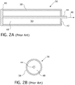
- Figure 2 provides a longitudinal cross section of a layout schematic of a miniature ion chamber 36 with Figure 2B showing a cross section taken orthogonal to the sectional view shown in Figure 2A .
- the miniature ion chamber 36 has an outer metal casing 38 that forms the outer electrode and insulated end caps 40 and 42 that support a central electrode 44. Similar in construction to the miniature fission chamber 10, the casing 38 surrounds a central chamber 50 that is filled with a fill gas 48.
- Each style of moveable detector has suboptimal performance characteristics that significantly increase the cost of operation of the detector system. Accordingly, an improved detector is desired that is more rugged and less expensive to operate than those currently employed.
- an ion chamber radiation detector with an enhanced fission gamma radiation response according to the invention, which is defined in claim 1.
- the ion chamber has an outer tubular electrode having an upper and lower end closed off by insulated end caps that electrically insulate the outer tubular electrode from a central electrode that substantially extends from the lower end cap up and through the upper end cap.
- An electron radiator that produces prompt neutron capture gamma radiation that is substantially, directly proportional to the local neutron population is disposed between the outer tubular electrode and the central electrode.
- the electron radiator is constructed from a material having a high Z value with which prompt neutron capture gamma radiation interacts through photoelectric and Compton scattering mechanisms.
- the electron radiator is constructed from one or more materials selected from a group of metals comprising platinum, gold, manganese, tungsten and cadmium and, more preferably, mainly from a group of metals comprising manganese, tungsten and cadmium.
- the electron radiator comprises a plurality of electron radiators that are spaced around the central electrode and preferably extends substantially between the lower end cap and the upper end cap.
- the invention also contemplates a nuclear reactor power distribution monitoring system having a plurality of in-core detectors that monitor power at different axial and radial locations within a core of the nuclear reactor. At least some of the in-core detectors comprise the foregoing ion chamber design. In one such embodiment, the ion chambers are moveable in-core detectors that substantially traverse an axial length of the core at different core radial locations.
- the primary side of nuclear power generating systems which are cooled with water under pressure comprises a closed circuit which is isolated from and in heat exchange relationship with a secondary side for the production of useful energy.
- the primary side comprises the reactor vessel enclosing a core internal structure that supports a plurality of fuel assemblies containing fissile material, the primary circuit within heat exchange steam generators, the inner volume of a pressurizer, pumps and pipes for circulating pressurized water; the pipes connecting each of the steam generators and pumps to the reactor vessel independently.
- Each of the parts of the primary side comprising a steam generator, a pump and a system of pipes which are connected to the vessel form a loop of the primary side.
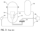
- Figure 3 shows a simplified nuclear reactor primary system, including a generally cylindrical reactor pressure vessel 52 having a closure head 68 enclosing a nuclear core 54.
- a liquid reactor coolant such as water
- a heat exchanger 58 typically referred to as a steam generator
- the reactor coolant is then returned to the pump 56 completing the primary loop.
- a plurality of the above described loops are connected to a single reactor pressure vessel 52 by reactor coolant piping 60. Though not shown, at least one such loop includes a pressurizer for maintaining the pressure in the system.
- moveable in-core detectors 62 are used by both boiling water reactors and pressurized water reactor style reactors to perform periodic detailed measurements of the core power distribution.
- the detectors 62 are inserted into the reactor core 54 during normal power operation according to a predetermined, intermittent, time program. Upon insertion, the detectors are automatically driven through the core region along fixed predetermined paths.
- the outputs of the detectors are recorded as a function of core location to provide a graphical representation of the reactor power distribution.
- the outputs of the detectors are fed through a seal table 64 to a control and monitoring system 66 responsible for implementing the time program.
- the moveable detectors 62 used are either primarily sensitive to neutron or gamma radiation.
- the gamma radiation detection device claimed hereafter utilizes a combination of the advantages of fission chamber style detectors and ion chamber style detectors to provide a detector capable of measuring the relative core power distribution in both pressurized water reactor and boiling water reactor style reactors that allows a significant reduction in the cost to own and operate the core power distribution measurement system.
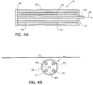
- Figures 4A and 4B provide a schematic of the preferred embodiment of the invention claimed hereafter.
- the fundamental difference between Figures 2A and 2B and 4A and 4B is the inclusion of an additional structure 72 in the ionization volume of the device, made of a metal such as natural manganese, tungsten or cadmium, which serves to produce high energy prompt neutron capture gamma radiation that is directly proportional to the local neutron population.
- This additional prompt neutron capture gamma radiation interacts through photoelectric and Compton scattering mechanisms with a high Z material, such as platinum or gold, surrounding the gamma radiator element to produce high energy electrons that also enhance the ionization in the gas fill 48 of the detector 70.
- This additional ionization greatly enhances the ionization current output 46 from the detector 70.
- This approach serves to enhance the signal level output from the device relative to the standard ion chamber 36 design without use of special nuclear material.
- the "Z" score in statistics, indicates how far and in what direction, that item deviates from its standard distribution mean. Expressed in units of its distribution standard deviation Z scores are sometimes called "standard scores.” The Z score transformation is especially useful when seeking to compare the relative standings of items from distributions with different means and/or different standard deviations.
- a relatively inexpensive prompt gamma radiator such as manganese, tungsten or cadmium allows the sensitive portion of the detector to be easily contained in a very robust physical package. Since the prompt sensitivity to the local neutron population is enhanced relative to the standard ion chamber 36, the uncertainty in the relationship between the signal and the true local core power level is reduced. The increase in the output signal from the stimulation of the local power distribution reduces or eliminates the need for extremely sensitive and expensive signal measurement electronics.
- This device will allow the use of the existing moveable detector signal measurement electronics so that the cost of implementation of this detector design will be minimized.
- This device may also be used as a stationary detector in other ion chamber applications where enhanced neutron sensitivity is a benefit, such as in reactor power level monitoring applications.
Landscapes
- Physics & Mathematics (AREA)
- High Energy & Nuclear Physics (AREA)
- Engineering & Computer Science (AREA)
- Plasma & Fusion (AREA)
- General Engineering & Computer Science (AREA)
- Health & Medical Sciences (AREA)
- Life Sciences & Earth Sciences (AREA)
- General Physics & Mathematics (AREA)
- Molecular Biology (AREA)
- Spectroscopy & Molecular Physics (AREA)
- Measurement Of Radiation (AREA)
- Monitoring And Testing Of Nuclear Reactors (AREA)
Claims (5)
- lonenkammer-Strahlungsdetektor (70) mit erhöhter Ansprache auf Spaltungs-Gammastrahlung, wobei der Detektor umfasst:eine Ionenkammer (36) miteiner rohrförmigen äußeren Elektrode (38), die ein oberes und ein unteres Ende aufweist;eine untere, elektrisch isolierte Endkappe (40), die das untere Ende der rohrförmigen äußeren Elektrode (38) verschließt;eine obere, elektrisch isolierte Endkappe (42), die das obere Ende der rohrförmigen äußeren Elektrode (38) verschließt;eine zentrale Elektrode (44), die sich im Wesentlichen von der unteren Endkappe (40) nach oben und durch die obere Endkappe (42) hindurch erstreckt,sowie eine Gasfüllung (48),dadurch gekennzeichnet, dass er ferner umfasst:eine Vielzahl von zylindrischen Elektronenstrahlerstäben (72), die um die zentrale Elektrode (44) herum voneinander beabstandet sind und von der rohrförmigen äußeren Elektrode (38) beabstandet sind, wobei sich die Elektronenstrahler (72) im Wesentlichen zwischen der unteren Endkappe (40) und der oberen Endkappe (42) erstrecken, wobei die Elektronenstrahler (72) zwischen der rohrförmigen äußeren Elektrode (38) und der zentralen Elektrode (44) angeordnet sind,wobei die Elektronenstrahler (72) dazu ausgestaltet sind, eine prompte Neutroneneinfang-Gammastrahlung zu erzeugen, die im Wesentlichen direkt proportional zu der lokalen Neutronenpopulation ist, wobei die Elektronenstrahler (72) aus einem Material mit einem hohen Z-Wert konstruiert sind, mit welchem die prompte Neutroneneinfang-Gammastrahlung durch photoelektrische und Compton-Streuungs-Mechanismen interagiert, und wobei jeder Elektronenstrahler (72) zumindest zum Teil mit Platin oder Gold oder mit beiden beschichtet ist.
- Ionenkammer-Strahlungsdetektor (70) nach Anspruch 1, wobei der Elektronenstrahler (72) aus einem oder mehreren Materialien hergestellt ist, die aus der Gruppe von Metallen umfassend Platin, Gold, Mangan, Wolfram und Kadmium ausgewählt sind.
- Ionenkammer-Strahlungsdetektor (70) nach Anspruch 1, wobei der Elektronenstrahler (72) hauptsächlich aus einer Gruppe von Metallen hergestellt ist, die Mangan, Wolfram und Kadmium umfasst.
- System (66) zur Überwachung der Leistungsverteilung in einem Kernreaktor, mit einer Vielzahl von kerninternen Detektoren (62), die dazu ausgestaltet sind, die Leistung an verschiedenen axialen und radialen Positionen innerhalb eines Kerns (54) des Kernreaktors (52) zu überwachen, wobei die kerninternen Detektoren Ionenkammer-Strahlungsdetektoren (70) nach einem der Ansprüche 1 bis 3 umfassen.
- System (66) zur Überwachung der Leistungsverteilung in einem Kernreaktor nach Anspruch 4, wobei die Ionenkammern (70) bewegliche kerninterne Detektoren sind, die dazu ausgestaltet sind, im Wesentlichen eine axiale Länge des Kerns (54) an verschiedenen radialen Positionen innerhalb des Kerns zu durchqueren.
Applications Claiming Priority (2)
| Application Number | Priority Date | Filing Date | Title |
|---|---|---|---|
| US13/974,384 US10109380B2 (en) | 2013-08-23 | 2013-08-23 | Ion chamber radiation detector |
| PCT/US2014/051041 WO2015026619A1 (en) | 2013-08-23 | 2014-08-14 | Ion chamber radiation detector |
Publications (3)
| Publication Number | Publication Date |
|---|---|
| EP3036745A1 EP3036745A1 (de) | 2016-06-29 |
| EP3036745A4 EP3036745A4 (de) | 2017-03-22 |
| EP3036745B1 true EP3036745B1 (de) | 2018-04-04 |
Family
ID=52480379
Family Applications (1)
| Application Number | Title | Priority Date | Filing Date |
|---|---|---|---|
| EP14838642.8A Active EP3036745B1 (de) | 2013-08-23 | 2014-08-14 | Ionisationskammerstrahlungsdetektor |
Country Status (8)
| Country | Link |
|---|---|
| US (1) | US10109380B2 (de) |
| EP (1) | EP3036745B1 (de) |
| JP (1) | JP6334704B2 (de) |
| KR (1) | KR102254441B1 (de) |
| CN (1) | CN105493197B (de) |
| ES (1) | ES2672347T3 (de) |
| NO (1) | NO3049733T3 (de) |
| WO (1) | WO2015026619A1 (de) |
Families Citing this family (14)
| Publication number | Priority date | Publication date | Assignee | Title |
|---|---|---|---|---|
| US8786510B2 (en) | 2006-01-24 | 2014-07-22 | Avery Dennison Corporation | Radio frequency (RF) antenna containing element and methods of making the same |
| US8981936B2 (en) | 2010-06-14 | 2015-03-17 | Avery Dennison Corporation | Method of manufacturing conductive structures |
| US9640290B2 (en) * | 2014-01-21 | 2017-05-02 | Westinghouse Electric Company Llc | Solid state electrical generator |
| KR101730887B1 (ko) | 2015-08-24 | 2017-04-28 | 주식회사 에프티랩 | 이중 탐침 구조화 된 이온화 챔버 및 차동 증폭기를 이용한 알파입자 검출 장치 |
| EP3467843B1 (de) * | 2016-05-24 | 2020-08-05 | Hitachi, Ltd. | Reaktorausgangsüberwachungsvorrichtung |
| WO2018033908A1 (en) * | 2016-08-14 | 2018-02-22 | Nuclear Research Center Negev | Neutron detector and method for its preparation |
| CN108109709B (zh) * | 2017-12-21 | 2025-01-10 | 中国原子能科学研究院 | 堆内高温电离室悬挂装置 |
| US11289236B2 (en) * | 2018-06-14 | 2022-03-29 | Westinghouse Electric Company Llc | Combination reactor gamma radiation power harvesting reactor power distribution measurement, and support to coolant freezing protection system for liquid metal and molten salt-cooled reactor systems |
| US11250967B2 (en) * | 2018-06-14 | 2022-02-15 | Westinghouse Electric Company Llc | Method and apparatus for enhancing the electrical power output of a nuclear reactor power generation system |
| US11170903B2 (en) | 2019-06-12 | 2021-11-09 | Westinghouse Electric Company Llc | Method and system to detect and locate the in-core position of fuel bundles with cladding perforations in candu-style nuclear reactors |
| CN111370290B (zh) * | 2020-04-10 | 2025-03-25 | 西北核技术研究院 | 抽样式裂变电离室及基于其测定裂变总数的方法 |
| US12046386B2 (en) * | 2020-05-19 | 2024-07-23 | Westinghouse Electric Company Llc | Method for periodically measuring the total gamma radiation activity of a target radioisotope being produced inside a nuclear reactor core |
| US11715577B2 (en) * | 2021-03-03 | 2023-08-01 | Westinghouse Electric Company Llc | Detectors, systems, and methods for continuously monitoring neutrons with enhanced sensitivity |
| CN116543939B (zh) * | 2023-05-10 | 2024-04-26 | 兰州大学 | 一种中子能谱测量装置 |
Family Cites Families (18)
| Publication number | Priority date | Publication date | Assignee | Title |
|---|---|---|---|---|
| US3760183A (en) * | 1972-06-08 | 1973-09-18 | Gen Electric | Neutron detector system |
| US3932211A (en) | 1973-07-13 | 1976-01-13 | Westinghouse Electric Corporation | Method of automatically monitoring the power distribution of a nuclear reactor employing movable incore detectors |
| JPS5567674A (en) | 1978-11-17 | 1980-05-21 | Toshiba Corp | Detector for neutron in atomic reactor |
| US4501988A (en) * | 1982-04-01 | 1985-02-26 | Harshaw/Filtrol Partnership | Ethylene quenched multi-cathode Geiger-Mueller tube with sleeve-and-screen cathode |
| US4516050A (en) | 1982-07-14 | 1985-05-07 | Varian Associates, Inc. | Ion chamber for electron-bombardment ion sources |
| US4590401A (en) | 1983-02-25 | 1986-05-20 | Westinghouse Electric Corp. | Ion chamber with a flat sensitivity response characteristic |
| US4623508A (en) | 1984-02-15 | 1986-11-18 | Reuter-Stokes, Inc. | Wide range flux monitor assembly |
| ES2018266B3 (es) | 1986-06-19 | 1991-04-01 | Westinghouse Electric Corp | Detector de nivel bajo. |
| US4859854A (en) | 1987-04-16 | 1989-08-22 | Femto-Tech, Inc. | Open grid pulsed ion chamber operating in the linear ion collection region |
| NL9201614A (nl) | 1991-12-20 | 1993-07-16 | Kema Nv | Turbine-meter voor nucleaire koelmiddelstroom. |
| JP3959188B2 (ja) | 1998-11-12 | 2007-08-15 | 株式会社東芝 | ストリップ電極型放射線検出装置 |
| US20070018110A1 (en) | 2004-07-29 | 2007-01-25 | Mcgregor Douglas S | Micro neutron detectors |
| JP2007163209A (ja) | 2005-12-12 | 2007-06-28 | Chugoku Electric Power Co Inc:The | 原子炉出力分布測定システム及び原子炉出力分布測定方法 |
| US8044365B2 (en) | 2008-08-18 | 2011-10-25 | Standard Imaging, Inc. | High-resolution ion chamber |
| CN101526623B (zh) * | 2009-03-31 | 2012-01-18 | 重庆大学 | 高能x射线工业ct电离型探测器 |
| KR101188681B1 (ko) | 2010-08-23 | 2012-10-09 | 한국수력원자력 주식회사 | 감마선 및 중성자를 구분하여 측정할 수 있는 방사선 검출 장치 |
| US8681920B2 (en) | 2011-01-07 | 2014-03-25 | Westinghouse Electric Company Llc | Self-powered wireless in-core detector |
| US8767903B2 (en) | 2011-01-07 | 2014-07-01 | Westinghouse Electric Company Llc | Wireless in-core neutron monitor |
-
2013
- 2013-08-23 US US13/974,384 patent/US10109380B2/en active Active
-
2014
- 2014-08-14 JP JP2016536320A patent/JP6334704B2/ja not_active Expired - Fee Related
- 2014-08-14 WO PCT/US2014/051041 patent/WO2015026619A1/en not_active Ceased
- 2014-08-14 CN CN201480046605.2A patent/CN105493197B/zh not_active Expired - Fee Related
- 2014-08-14 ES ES14838642.8T patent/ES2672347T3/es active Active
- 2014-08-14 KR KR1020167007335A patent/KR102254441B1/ko not_active Expired - Fee Related
- 2014-08-14 EP EP14838642.8A patent/EP3036745B1/de active Active
-
2015
- 2015-07-28 NO NO15827258A patent/NO3049733T3/no unknown
Non-Patent Citations (1)
| Title |
|---|
| None * |
Also Published As
| Publication number | Publication date |
|---|---|
| JP2017501397A (ja) | 2017-01-12 |
| EP3036745A1 (de) | 2016-06-29 |
| KR20160046852A (ko) | 2016-04-29 |
| KR102254441B1 (ko) | 2021-05-20 |
| WO2015026619A1 (en) | 2015-02-26 |
| US20150055742A1 (en) | 2015-02-26 |
| JP6334704B2 (ja) | 2018-05-30 |
| NO3049733T3 (de) | 2018-02-24 |
| US10109380B2 (en) | 2018-10-23 |
| CN105493197A (zh) | 2016-04-13 |
| EP3036745A4 (de) | 2017-03-22 |
| ES2672347T3 (es) | 2018-06-14 |
| CN105493197B (zh) | 2018-03-30 |
Similar Documents
| Publication | Publication Date | Title |
|---|---|---|
| EP3036745B1 (de) | Ionisationskammerstrahlungsdetektor | |
| US10438708B2 (en) | In-core instrument thimble assembly | |
| EP2661752B1 (de) | Drahtloser in-core-neutronen-monitor | |
| US8445839B2 (en) | Self-calibrating, highly accurate, long-lived, dual rhodium vanadium emitter nuclear in-core detector | |
| EP2449558B1 (de) | Verfahren zur überprüfung der leistung eines kerns mittels instrumentierung des kerns | |
| US10910117B2 (en) | Wirelessly emitting signals corresponding to detected neutron flux | |
| EP2661644B1 (de) | Selbstangetriebener drahtloser in-core-detektor | |
| EP3374996B1 (de) | Subkritischer reaktivitätsmonitor mit unverzüglichen selbstangetriebenen incore-detektoren | |
| US4208247A (en) | Neutron source | |
| US5015434A (en) | Fixed in-core calibration devices for BWR flux monitors | |
| KR20170030615A (ko) | 열-음향 원자력 분포 측정 조립체 | |
| EP2992532B1 (de) | Autonom betriebener nukleardetektor | |
| O'Kelly | The advanced test reactor | |
| JP4625557B2 (ja) | 原子炉出力監視装置 | |
| Imel et al. | The performance of hafnium and gadolinium self powered neutron detectors in the TREAT reactor | |
| Abuqudaira et al. | Assessment of nuclear sensors and instrumentation maturity in advanced nuclear reactors | |
| Abuqudaira et al. | Instrumentation Maturity in |
Legal Events
| Date | Code | Title | Description |
|---|---|---|---|
| PUAI | Public reference made under article 153(3) epc to a published international application that has entered the european phase |
Free format text: ORIGINAL CODE: 0009012 |
|
| 17P | Request for examination filed |
Effective date: 20160208 |
|
| AK | Designated contracting states |
Kind code of ref document: A1 Designated state(s): AL AT BE BG CH CY CZ DE DK EE ES FI FR GB GR HR HU IE IS IT LI LT LU LV MC MK MT NL NO PL PT RO RS SE SI SK SM TR |
|
| AX | Request for extension of the european patent |
Extension state: BA ME |
|
| DAX | Request for extension of the european patent (deleted) | ||
| A4 | Supplementary search report drawn up and despatched |
Effective date: 20170222 |
|
| RIC1 | Information provided on ipc code assigned before grant |
Ipc: H01J 47/08 20060101AFI20170216BHEP Ipc: G21C 17/108 20060101ALI20170216BHEP Ipc: G01T 3/00 20060101ALI20170216BHEP |
|
| REG | Reference to a national code |
Ref country code: DE Ref legal event code: R079 Ref document number: 602014023498 Country of ref document: DE Free format text: PREVIOUS MAIN CLASS: G21C0017060000 Ipc: H01J0047080000 |
|
| GRAP | Despatch of communication of intention to grant a patent |
Free format text: ORIGINAL CODE: EPIDOSNIGR1 |
|
| RIC1 | Information provided on ipc code assigned before grant |
Ipc: H01J 47/12 20060101ALI20171211BHEP Ipc: G21C 17/108 20060101ALI20171211BHEP Ipc: G01T 3/00 20060101ALI20171211BHEP Ipc: H01J 47/08 20060101AFI20171211BHEP |
|
| INTG | Intention to grant announced |
Effective date: 20180117 |
|
| GRAS | Grant fee paid |
Free format text: ORIGINAL CODE: EPIDOSNIGR3 |
|
| GRAA | (expected) grant |
Free format text: ORIGINAL CODE: 0009210 |
|
| AK | Designated contracting states |
Kind code of ref document: B1 Designated state(s): AL AT BE BG CH CY CZ DE DK EE ES FI FR GB GR HR HU IE IS IT LI LT LU LV MC MK MT NL NO PL PT RO RS SE SI SK SM TR |
|
| REG | Reference to a national code |
Ref country code: GB Ref legal event code: FG4D |
|
| REG | Reference to a national code |
Ref country code: CH Ref legal event code: EP |
|
| REG | Reference to a national code |
Ref country code: AT Ref legal event code: REF Ref document number: 986454 Country of ref document: AT Kind code of ref document: T Effective date: 20180415 |
|
| REG | Reference to a national code |
Ref country code: IE Ref legal event code: FG4D |
|
| REG | Reference to a national code |
Ref country code: DE Ref legal event code: R096 Ref document number: 602014023498 Country of ref document: DE |
|
| REG | Reference to a national code |
Ref country code: DE Ref legal event code: R082 Ref document number: 602014023498 Country of ref document: DE Representative=s name: FLEUCHAUS & GALLO PARTNERSCHAFT MBB PATENTANWA, DE Ref country code: DE Ref legal event code: R082 Ref document number: 602014023498 Country of ref document: DE Representative=s name: FLEUCHAUS & GALLO PARTNERSCHAFT MBB, DE |
|
| REG | Reference to a national code |
Ref country code: SE Ref legal event code: TRGR |
|
| REG | Reference to a national code |
Ref country code: NL Ref legal event code: FP |
|
| REG | Reference to a national code |
Ref country code: ES Ref legal event code: FG2A Ref document number: 2672347 Country of ref document: ES Kind code of ref document: T3 Effective date: 20180614 |
|
| REG | Reference to a national code |
Ref country code: NO Ref legal event code: T2 Effective date: 20180404 |
|
| REG | Reference to a national code |
Ref country code: FR Ref legal event code: PLFP Year of fee payment: 5 |
|
| REG | Reference to a national code |
Ref country code: LT Ref legal event code: MG4D |
|
| PG25 | Lapsed in a contracting state [announced via postgrant information from national office to epo] |
Ref country code: PL Free format text: LAPSE BECAUSE OF FAILURE TO SUBMIT A TRANSLATION OF THE DESCRIPTION OR TO PAY THE FEE WITHIN THE PRESCRIBED TIME-LIMIT Effective date: 20180404 Ref country code: LT Free format text: LAPSE BECAUSE OF FAILURE TO SUBMIT A TRANSLATION OF THE DESCRIPTION OR TO PAY THE FEE WITHIN THE PRESCRIBED TIME-LIMIT Effective date: 20180404 Ref country code: FI Free format text: LAPSE BECAUSE OF FAILURE TO SUBMIT A TRANSLATION OF THE DESCRIPTION OR TO PAY THE FEE WITHIN THE PRESCRIBED TIME-LIMIT Effective date: 20180404 Ref country code: BG Free format text: LAPSE BECAUSE OF FAILURE TO SUBMIT A TRANSLATION OF THE DESCRIPTION OR TO PAY THE FEE WITHIN THE PRESCRIBED TIME-LIMIT Effective date: 20180704 Ref country code: AL Free format text: LAPSE BECAUSE OF FAILURE TO SUBMIT A TRANSLATION OF THE DESCRIPTION OR TO PAY THE FEE WITHIN THE PRESCRIBED TIME-LIMIT Effective date: 20180404 |
|
| PG25 | Lapsed in a contracting state [announced via postgrant information from national office to epo] |
Ref country code: RS Free format text: LAPSE BECAUSE OF FAILURE TO SUBMIT A TRANSLATION OF THE DESCRIPTION OR TO PAY THE FEE WITHIN THE PRESCRIBED TIME-LIMIT Effective date: 20180404 Ref country code: LV Free format text: LAPSE BECAUSE OF FAILURE TO SUBMIT A TRANSLATION OF THE DESCRIPTION OR TO PAY THE FEE WITHIN THE PRESCRIBED TIME-LIMIT Effective date: 20180404 Ref country code: HR Free format text: LAPSE BECAUSE OF FAILURE TO SUBMIT A TRANSLATION OF THE DESCRIPTION OR TO PAY THE FEE WITHIN THE PRESCRIBED TIME-LIMIT Effective date: 20180404 Ref country code: GR Free format text: LAPSE BECAUSE OF FAILURE TO SUBMIT A TRANSLATION OF THE DESCRIPTION OR TO PAY THE FEE WITHIN THE PRESCRIBED TIME-LIMIT Effective date: 20180705 |
|
| REG | Reference to a national code |
Ref country code: AT Ref legal event code: MK05 Ref document number: 986454 Country of ref document: AT Kind code of ref document: T Effective date: 20180404 |
|
| PG25 | Lapsed in a contracting state [announced via postgrant information from national office to epo] |
Ref country code: PT Free format text: LAPSE BECAUSE OF FAILURE TO SUBMIT A TRANSLATION OF THE DESCRIPTION OR TO PAY THE FEE WITHIN THE PRESCRIBED TIME-LIMIT Effective date: 20180806 |
|
| REG | Reference to a national code |
Ref country code: DE Ref legal event code: R097 Ref document number: 602014023498 Country of ref document: DE |
|
| PG25 | Lapsed in a contracting state [announced via postgrant information from national office to epo] |
Ref country code: SK Free format text: LAPSE BECAUSE OF FAILURE TO SUBMIT A TRANSLATION OF THE DESCRIPTION OR TO PAY THE FEE WITHIN THE PRESCRIBED TIME-LIMIT Effective date: 20180404 Ref country code: DK Free format text: LAPSE BECAUSE OF FAILURE TO SUBMIT A TRANSLATION OF THE DESCRIPTION OR TO PAY THE FEE WITHIN THE PRESCRIBED TIME-LIMIT Effective date: 20180404 Ref country code: AT Free format text: LAPSE BECAUSE OF FAILURE TO SUBMIT A TRANSLATION OF THE DESCRIPTION OR TO PAY THE FEE WITHIN THE PRESCRIBED TIME-LIMIT Effective date: 20180404 Ref country code: RO Free format text: LAPSE BECAUSE OF FAILURE TO SUBMIT A TRANSLATION OF THE DESCRIPTION OR TO PAY THE FEE WITHIN THE PRESCRIBED TIME-LIMIT Effective date: 20180404 Ref country code: CZ Free format text: LAPSE BECAUSE OF FAILURE TO SUBMIT A TRANSLATION OF THE DESCRIPTION OR TO PAY THE FEE WITHIN THE PRESCRIBED TIME-LIMIT Effective date: 20180404 Ref country code: EE Free format text: LAPSE BECAUSE OF FAILURE TO SUBMIT A TRANSLATION OF THE DESCRIPTION OR TO PAY THE FEE WITHIN THE PRESCRIBED TIME-LIMIT Effective date: 20180404 |
|
| PLBE | No opposition filed within time limit |
Free format text: ORIGINAL CODE: 0009261 |
|
| STAA | Information on the status of an ep patent application or granted ep patent |
Free format text: STATUS: NO OPPOSITION FILED WITHIN TIME LIMIT |
|
| PG25 | Lapsed in a contracting state [announced via postgrant information from national office to epo] |
Ref country code: SM Free format text: LAPSE BECAUSE OF FAILURE TO SUBMIT A TRANSLATION OF THE DESCRIPTION OR TO PAY THE FEE WITHIN THE PRESCRIBED TIME-LIMIT Effective date: 20180404 |
|
| 26N | No opposition filed |
Effective date: 20190107 |
|
| PG25 | Lapsed in a contracting state [announced via postgrant information from national office to epo] |
Ref country code: MC Free format text: LAPSE BECAUSE OF FAILURE TO SUBMIT A TRANSLATION OF THE DESCRIPTION OR TO PAY THE FEE WITHIN THE PRESCRIBED TIME-LIMIT Effective date: 20180404 |
|
| REG | Reference to a national code |
Ref country code: CH Ref legal event code: PL |
|
| PG25 | Lapsed in a contracting state [announced via postgrant information from national office to epo] |
Ref country code: LI Free format text: LAPSE BECAUSE OF NON-PAYMENT OF DUE FEES Effective date: 20180831 Ref country code: CH Free format text: LAPSE BECAUSE OF NON-PAYMENT OF DUE FEES Effective date: 20180831 Ref country code: LU Free format text: LAPSE BECAUSE OF NON-PAYMENT OF DUE FEES Effective date: 20180814 |
|
| REG | Reference to a national code |
Ref country code: IE Ref legal event code: MM4A |
|
| PG25 | Lapsed in a contracting state [announced via postgrant information from national office to epo] |
Ref country code: SI Free format text: LAPSE BECAUSE OF FAILURE TO SUBMIT A TRANSLATION OF THE DESCRIPTION OR TO PAY THE FEE WITHIN THE PRESCRIBED TIME-LIMIT Effective date: 20180404 |
|
| PG25 | Lapsed in a contracting state [announced via postgrant information from national office to epo] |
Ref country code: IE Free format text: LAPSE BECAUSE OF NON-PAYMENT OF DUE FEES Effective date: 20180814 |
|
| PG25 | Lapsed in a contracting state [announced via postgrant information from national office to epo] |
Ref country code: MT Free format text: LAPSE BECAUSE OF NON-PAYMENT OF DUE FEES Effective date: 20180814 |
|
| PG25 | Lapsed in a contracting state [announced via postgrant information from national office to epo] |
Ref country code: TR Free format text: LAPSE BECAUSE OF FAILURE TO SUBMIT A TRANSLATION OF THE DESCRIPTION OR TO PAY THE FEE WITHIN THE PRESCRIBED TIME-LIMIT Effective date: 20180404 |
|
| PG25 | Lapsed in a contracting state [announced via postgrant information from national office to epo] |
Ref country code: CY Free format text: LAPSE BECAUSE OF FAILURE TO SUBMIT A TRANSLATION OF THE DESCRIPTION OR TO PAY THE FEE WITHIN THE PRESCRIBED TIME-LIMIT Effective date: 20180404 Ref country code: MK Free format text: LAPSE BECAUSE OF NON-PAYMENT OF DUE FEES Effective date: 20180404 Ref country code: HU Free format text: LAPSE BECAUSE OF FAILURE TO SUBMIT A TRANSLATION OF THE DESCRIPTION OR TO PAY THE FEE WITHIN THE PRESCRIBED TIME-LIMIT; INVALID AB INITIO Effective date: 20140814 |
|
| PG25 | Lapsed in a contracting state [announced via postgrant information from national office to epo] |
Ref country code: IS Free format text: LAPSE BECAUSE OF FAILURE TO SUBMIT A TRANSLATION OF THE DESCRIPTION OR TO PAY THE FEE WITHIN THE PRESCRIBED TIME-LIMIT Effective date: 20180804 |
|
| REG | Reference to a national code |
Ref country code: DE Ref legal event code: R082 Ref document number: 602014023498 Country of ref document: DE Representative=s name: FLEUCHAUS & GALLO PARTNERSCHAFT MBB - PATENT- , DE Ref country code: DE Ref legal event code: R082 Ref document number: 602014023498 Country of ref document: DE Representative=s name: FLEUCHAUS & GALLO PARTNERSCHAFT MBB PATENTANWA, DE |
|
| PGFP | Annual fee paid to national office [announced via postgrant information from national office to epo] |
Ref country code: NL Payment date: 20250714 Year of fee payment: 12 |
|
| PGFP | Annual fee paid to national office [announced via postgrant information from national office to epo] |
Ref country code: ES Payment date: 20250911 Year of fee payment: 12 |
|
| PGFP | Annual fee paid to national office [announced via postgrant information from national office to epo] |
Ref country code: DE Payment date: 20250714 Year of fee payment: 12 |
|
| PGFP | Annual fee paid to national office [announced via postgrant information from national office to epo] |
Ref country code: NO Payment date: 20250714 Year of fee payment: 12 |
|
| PGFP | Annual fee paid to national office [announced via postgrant information from national office to epo] |
Ref country code: IT Payment date: 20250714 Year of fee payment: 12 |
|
| PGFP | Annual fee paid to national office [announced via postgrant information from national office to epo] |
Ref country code: BE Payment date: 20250819 Year of fee payment: 12 Ref country code: GB Payment date: 20250821 Year of fee payment: 12 |
|
| PGFP | Annual fee paid to national office [announced via postgrant information from national office to epo] |
Ref country code: FR Payment date: 20250818 Year of fee payment: 12 |
|
| PGFP | Annual fee paid to national office [announced via postgrant information from national office to epo] |
Ref country code: SE Payment date: 20250812 Year of fee payment: 12 |