EP3036600B1 - Verfahren und steuerung zur leistungsdrosselung eines systems auf einer tragbaren vorrichtung, entsprechende tragbare vorrichtung und entsprechendes computerprogrammprodukt - Google Patents
Verfahren und steuerung zur leistungsdrosselung eines systems auf einer tragbaren vorrichtung, entsprechende tragbare vorrichtung und entsprechendes computerprogrammprodukt Download PDFInfo
- Publication number
- EP3036600B1 EP3036600B1 EP14865747.1A EP14865747A EP3036600B1 EP 3036600 B1 EP3036600 B1 EP 3036600B1 EP 14865747 A EP14865747 A EP 14865747A EP 3036600 B1 EP3036600 B1 EP 3036600B1
- Authority
- EP
- European Patent Office
- Prior art keywords
- output current
- available
- battery
- characteristic
- power range
- Prior art date
- Legal status (The legal status is an assumption and is not a legal conclusion. Google has not performed a legal analysis and makes no representation as to the accuracy of the status listed.)
- Active
Links
Images


Classifications
-
- G—PHYSICS
- G06—COMPUTING OR CALCULATING; COUNTING
- G06F—ELECTRIC DIGITAL DATA PROCESSING
- G06F1/00—Details not covered by groups G06F3/00 - G06F13/00 and G06F21/00
- G06F1/26—Power supply means, e.g. regulation thereof
- G06F1/32—Means for saving power
- G06F1/3203—Power management, i.e. event-based initiation of a power-saving mode
- G06F1/3206—Monitoring of events, devices or parameters that trigger a change in power modality
- G06F1/3212—Monitoring battery levels, e.g. power saving mode being initiated when battery voltage goes below a certain level
-
- G—PHYSICS
- G06—COMPUTING OR CALCULATING; COUNTING
- G06F—ELECTRIC DIGITAL DATA PROCESSING
- G06F1/00—Details not covered by groups G06F3/00 - G06F13/00 and G06F21/00
- G06F1/26—Power supply means, e.g. regulation thereof
- G06F1/32—Means for saving power
- G06F1/3203—Power management, i.e. event-based initiation of a power-saving mode
- G06F1/3234—Power saving characterised by the action undertaken
- G06F1/3287—Power saving characterised by the action undertaken by switching off individual functional units in the computer system
-
- G—PHYSICS
- G06—COMPUTING OR CALCULATING; COUNTING
- G06F—ELECTRIC DIGITAL DATA PROCESSING
- G06F1/00—Details not covered by groups G06F3/00 - G06F13/00 and G06F21/00
- G06F1/26—Power supply means, e.g. regulation thereof
- G06F1/32—Means for saving power
- G06F1/3203—Power management, i.e. event-based initiation of a power-saving mode
- G06F1/3234—Power saving characterised by the action undertaken
- G06F1/329—Power saving characterised by the action undertaken by task scheduling
-
- H—ELECTRICITY
- H04—ELECTRIC COMMUNICATION TECHNIQUE
- H04W—WIRELESS COMMUNICATION NETWORKS
- H04W52/00—Power management, e.g. Transmission Power Control [TPC] or power classes
- H04W52/02—Power saving arrangements
- H04W52/0209—Power saving arrangements in terminal devices
- H04W52/0261—Power saving arrangements in terminal devices managing power supply demand, e.g. depending on battery level
- H04W52/0264—Power saving arrangements in terminal devices managing power supply demand, e.g. depending on battery level by selectively disabling software applications
-
- Y—GENERAL TAGGING OF NEW TECHNOLOGICAL DEVELOPMENTS; GENERAL TAGGING OF CROSS-SECTIONAL TECHNOLOGIES SPANNING OVER SEVERAL SECTIONS OF THE IPC; TECHNICAL SUBJECTS COVERED BY FORMER USPC CROSS-REFERENCE ART COLLECTIONS [XRACs] AND DIGESTS
- Y02—TECHNOLOGIES OR APPLICATIONS FOR MITIGATION OR ADAPTATION AGAINST CLIMATE CHANGE
- Y02D—CLIMATE CHANGE MITIGATION TECHNOLOGIES IN INFORMATION AND COMMUNICATION TECHNOLOGIES [ICT], I.E. INFORMATION AND COMMUNICATION TECHNOLOGIES AIMING AT THE REDUCTION OF THEIR OWN ENERGY USE
- Y02D10/00—Energy efficient computing, e.g. low power processors, power management or thermal management
-
- Y—GENERAL TAGGING OF NEW TECHNOLOGICAL DEVELOPMENTS; GENERAL TAGGING OF CROSS-SECTIONAL TECHNOLOGIES SPANNING OVER SEVERAL SECTIONS OF THE IPC; TECHNICAL SUBJECTS COVERED BY FORMER USPC CROSS-REFERENCE ART COLLECTIONS [XRACs] AND DIGESTS
- Y02—TECHNOLOGIES OR APPLICATIONS FOR MITIGATION OR ADAPTATION AGAINST CLIMATE CHANGE
- Y02D—CLIMATE CHANGE MITIGATION TECHNOLOGIES IN INFORMATION AND COMMUNICATION TECHNOLOGIES [ICT], I.E. INFORMATION AND COMMUNICATION TECHNOLOGIES AIMING AT THE REDUCTION OF THEIR OWN ENERGY USE
- Y02D30/00—Reducing energy consumption in communication networks
- Y02D30/70—Reducing energy consumption in communication networks in wireless communication networks
Definitions
- a conventional scheme may employ a conventional protection circuit to protect a power source such as a battery.
- the conventional protection circuit may be used for disabling a system operating on a portable device or disabling a system application when the battery temperature is higher than a threshold, so as to achieve protection for the battery.
- the conventional protection circuit may be used for disabling the system when the battery voltage is lower than a minimum voltage threshold or the residual battery capacity is lower than a minimum capacity threshold, for protecting the battery.
- the above-mentioned thresholds are usually configured and fixed for the battery before the battery goes out of the factory. However, characteristic of the battery may be changed after use. Accordingly, it is not appropriate to employ the conventional thresholds mentioned above for protecting the battery all the time. In addition, characteristic of the battery may be varied with other factors that are not considered by the conventional scheme. For precisely protecting the battery, it is not enough to merely consider voltage, battery capacity, or battery temperature.
- US 2013/254579 A1 discloses a method for power throttling a system according to the preamble of claim 1. Methods for power throttling involving obtaining at least one characteristic of a power source and adjusting an available power range are shown in any one of US 2012/239949 A1 , US 2002/093311 A1 , US 2012/210150 A1 and US 2008/200220 A1 .
- one of the objectives of the present invention is to provide a method, a controller, and a computer program product for dynamically power throttling upon a system operating on a portable device according to characteristic information of a power source, so as to provide the safety for the power source and also improve the system performance and the energy usage efficiency.
- Another one of the objectives of the present invention is to provide a portable device and a computer program product for dynamically adjusting a system performance according to characteristic information of a power source, so as to provide the safety for the power source and also improve the system performance and the energy usage efficiency.
- a method for power throttling a system is defined in independent claim 1 and a controller for power throttling a system is defined in independent claim 5.
- the dependent claims define preferred embodiments thereof, respectively.
- a computer program product for power throttling a system according to the present invention is defined in claim 10 and a portable device capable of performing power throttling according to the present invention is defined in claim 8.
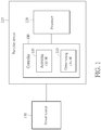
- FIG. 1 is a diagram of a controller 100 for power throttling upon a system according to an embodiment of the present invention.
- the operation of power throttling is used for adaptively/dynamically adjusting available power level/range for the system operating on the portable device 115.
- this power throttling operation is performed based on the state/characteristic of a power source 130 such as a battery or an adaptor; the battery can be a primary battery cell and/or a secondary battery cell (i.e. rechargeable battery cell).
- the system on the portable device 115 is arranged to operate according to the dynamically adjusted power level/range and may adaptively enable/disable at least one application or operation under different conditions.
- the processor 120 is responsible to execute, enable, disable, or interrupt software programs/applications of the system. Thus, this can improve the performance of system as far as possible under the safety range of power source 130. It should be noted that the above-mentioned scheme can be used for power throttling a system that does not operate on a portable device. This also falls within the scope of the invention.
- the controller 100 is arranged to determine an available power range for the system (or the processor 120) initially and immediately or dynamically update the available power range according to characteristic information of the power source 130 so as to make the system (or processor 120) be capable of adaptively employing the appropriate power range to execute programs or applications.
- the available power range indicates an available power level that can be consumed by the system. That is, the controller 100 is responsible for deciding the available power level for the system to make the system operate under the condition of available power level.
- the processor 120 can adaptively disable/enable some applications so that the system can adjust its behavior or operation by itself.
- the power source 130 for example comprises a battery and a circuit board connected between the battery and the system.
- the characteristic information of power source 130 may comprise one kind of state/characteristic of power source 130 or multiple kinds of state/characteristic.
- the characteristic information may comprise at least one of a voltage of the battery, a current of the battery, a temperature (e.g. environmental temperature) of the power source 130, an inner impedance of the battery, an impedance (e.g. parasitic impedance) of the circuit board, a total capacity of the battery, a residual capacity of the battery, an expansion coefficient of the battery, and protection parameter(s) of the battery, and so on.
- the controller 100 is arranged to perform power throttling based on at least all the characteristic information mentioned above so as to precisely improve the performance of system under the safety range of battery.
- the controller 100 can also perform power throttling based on at least two kinds of characteristic information. Other different kinds of characteristic information may be referenced by the controller 100.
- the processor 120 may be a multicore processor needing to consume large current. If a small battery (including small capacity) is connected to the portable device 115 for providing a small current for the system, a multicore system without a reference of the available power range may directly shut down since the current provided for the multicore system is not enough. In this embodiment, the multicore system based on the reference of available power range can adjust its behavior or operation adaptively. Thus, the multicore system based on the reference of available power range does not shut down and may temporarily disable or turn off some application/operation that consume large current.
- the multicore system without the reference of available power range may suddenly consume over much energy of the small battery to cause the small battery damaged.
- the multicore system based on the reference of available power range can prevent the battery from damaged and improve the safety of battery. This can also improve the efficiency of battery usage for the system.
- the method disclosed in the embodiment can make the system on the portable device 115 intelligently adjust its performance according to the different kinds of power sources.
- the controller 100 comprises an acquiring circuit 105 and a determining circuit 110.
- the acquiring circuit 105 is used for obtaining at least one characteristic information of the power source 130 that is used for providing energy for the system of portable device 115.
- the acquiring circuit 105 can be arranged to obtain/update the characteristic information by measuring/estimating the power source 130 and/or by receiving the characteristic information from another external data source or the power source 130.
- the acquiring circuit 105 can receive the protection parameter(s) from the power source 130 such as the battery.
- the acquiring circuit 105 can estimate or detect the power source 130 to obtain/calculate the protection parameter(s).
- the acquiring circuit 105 can also estimate other kinds of characteristic information such as the inner impedance, the impedance of trace on the circuit board, the voltage, current, temperature, and so on.
- the acquiring circuit 105 can be implemented by using an expansion sensor for sensing battery deformation to determine whether the battery inflates.
- the determining circuit 110 is coupled the acquiring circuit 105 and used for determining or updating the available power range for the system according to the at least one characteristic information, so as to make the system dynamically control its behavior/operation according to the available power range that is dynamically updated. For example, the determining circuit 110 can update the available power range according to the updated characteristic information each time when the battery percentage changes. According to the currently updated available power range, the system (or the processor 120) can adaptively adjust its power consumption. When the currently updated available power range indicates a lower available power level, the system (or the processor 120) may merely enable some applications consuming a lower power level and is not arranged to enable some applications consuming a higher power level.
- the system may enable the applications consuming the lower power level and the applications consuming the higher power level. Equivalently, the system (or the processor 120) dynamically adjusts the operations or applications based on the updated characteristic information of power source 130.
- the available power level is configured to be higher than a maximum power level that can be used by the system to operate. In reality, it is acceptable that the system may suddenly consume more power than the available power level but still lower than the maximum power level. In this situation, when the system consumes over much energy, the battery percentage may rapidly change, and the acquiring circuit 105 immediately updates the characteristic information.
- the determining circuit 110 immediately makes the system (or the processor 120) adjust at least one operation of system according to the updated characteristic information. For instance, if the system instantaneously consumes over much energy on providing backlight to a display panel of portable device 115, the acquiring circuit 105 is arranged to obtain/generate the updated characteristic information such as residual capacity of battery or inner impedance, and so on.
- the determining circuit 110 Based on the updated characteristic information, the determining circuit 110 instantaneously determines/updates the available power range/level for the system (or the processor 120) so as to make the system adjust its backlight operation. For example, the determining circuit 110 may decrease the available power range to a smaller power range, and the system based on the smaller power range may reduce its backlight. When the backlight is decreased, the system does not yet consume over much power on providing backlight. Thus, by dynamically/periodically updating the available power range/level, this can prevent the system from continuing consuming over high power level so as to guarantee the safety of power source 130.
- the available power range may be configured to include an averagely available power range and an immediately available power range.
- the available power range comprises the averagely available power range and immediately available power range.
- the averagely available power range indicates an available power level that can be averagely consumed by the system
- the immediately available power range indicates a available power level that can be instantaneously consumed by the system, i.e. an acceptable peak power level.
- the immediately available power range is configured to be broader than the averagely available power range; that is, the peak power level is configured to be higher than the available power level which can be averagely consumed by the system; however, this is not meant to be a limitation of the present invention.
- the acceptable peak power level is not higher than the maximum peak power level that may be provided for the system.
- the determining circuit 110 is arranged to determine the averagely available power range and the immediately available power range for the system for making the system decide whether to enable/disable some applications or some operations temporarily by itself.
- the averagely available power range and the immediately available power range can be regarded as different power thresholds for alerting the system. For example, when the power level consumed by the system does not exceed above the averagely available power range, the system is not arranged to disable some applications/operations that are currently performed or executed.
- the system may be arranged to merely disable some portion of currently performed applications/operations but does not temporarily disable most currently performed applications/operations. If the power level consumed by the system exceeds above the immediately available power range, in order to rapidly decrease the power level consumed by the system to improve safety of battery, the system may temporarily disable most currently performed applications/operations. Thus, by two-stage adjusting for power level, this can maximize the efficiency of power/energy usage for the system under the condition of battery safety.
- the determining circuit 110 can be dynamically update and output the averagely available power range and the immediately available power range for the system so that the system can adaptively adjust its behavior, application(s), or operation(s) based on the currently updated state/characteristic of battery.
- the averagely available power range indicates an averagely available output current or a corresponding available output voltage drop that can be averagely accepted by the power source
- the immediately available power range indicates an immediately available output current or a corresponding available output voltage drop that can be immediately accepted by the power source.
- the determining circuit 110 calculates/updates the averagely available output current and the immediately available output current for the system; in other embodiments, the determining circuit 110 can also calculate/update an averagely available output voltage drop and an immediately available output voltage drop for the system.
- FIG. 2 is a diagram illustrating an example that the system dynamically adjusts its behavior based on the averagely available output voltage drop and the immediately available output voltage drop according to the embodiment of the present invention. As shown in FIG.
- curve CV1 indicates the change of residual battery energy percentage with time
- curve CV2 indicates a voltage level of battery actually caused by the operation/application of the system.
- CV2 shows that the necessary output current actually provided from the battery to the system may change with different applications/operations and the system is arranged to dynamically/adaptively disable or enable some applications/operations so as to extend the lifetime of battery and improve the efficiency of energy usage as far as possible.
- CV2 indicates that the voltage level changes when the system dynamically enables/disables some applications.
- TH1 is a voltage threshold indicating a minimum voltage level required by the system to operate. When the system voltage becomes lower than the voltage threshold TH1, the system is arranged to shut down.
- TH2 is a voltage threshold indicating a level corresponding to the immediately available output voltage drop.
- TH3 is a voltage threshold indicating a level corresponding to the averagely available output voltage drop.
- the actual voltage level becomes lower due to a significant voltage drop on the output voltage of battery caused by a large current provided from the battery.
- the actual voltage level becomes lower than the voltage threshold TH3, and this indicates that a power level actually consumed by the system exceeds above the averagely available power range.
- the system initiates an interrupt to temporarily disable some applications or some operations at timing T2.
- the actual voltage level becomes lower and reaches the voltage threshold TH3 again, and the system also initiates interrupts to temporarily disable some applications or some operations at timings T3 and T4.
- the system becomes idle (background applications are still running) and it is not required for the system to consume a large current from the battery.
- the system is arranged to release the above-mentioned interrupt(s). That is, if it is required, the system is allowed to execute the application(s) or operation(s) that consume large currents.
- the system may enable some application(s) consuming larger currents, and then a significant voltage drop occurs on the actual voltage level of battery.
- the significant voltage drop causes the actual voltage level be rapidly decreased and directly reaches the voltage threshold TH2.
- the system is arranged immediately initiate an interrupt to temporarily disable application(s) or operation(s) that is/are currently running and consuming large currents.
- the system becomes idle again (background applications are still running) and it is not required for the system to consume large currents from the battery.
- the actual voltage level of battery may become higher than the level TH4, and the system releases the above-mentioned interrupt(s) again.
- the residual battery capacity may be not enough for basic application(s)/operation(s) of the system, and the system may shut down.
- the determining circuit 110 can make the system to dynamically adjust its at least one operation/application to make a first proportion of decrease in the required current amount provided for the system in response to an event of the actual voltage level of battery becoming lower than the voltage threshold TH3 due to that the voltage drop occurring on the actual voltage level becomes higher than the averagely available output voltage drop.
- the determining circuit 110 can also make the system to dynamically adjust its at least one operation/application to make a second proportion of decrease in the required current amount provided for the system in response to an event of the actual voltage level of battery becoming lower than the voltage threshold TH2 due to that the voltage drop occurring on the actual voltage level becomes higher than the immediately available output voltage drop.
- the averagely available output voltage drop corresponds to the averagely available output current
- the immediately available output voltage drop corresponds to the immediately available output current.
- the determining circuit 110 makes the system to dynamically adjust its at least one operation/application to make the first proportion of decrease in the required current amount provided for the system in response to an event of the actual output current of battery becoming higher than the averagely available output current, and makes the system to dynamically adjust its at least one operation/application to make the second proportion of decrease in the required current amount provided for the system in response to an event of the actual output current of battery becoming higher than the immediately available output current.
- the first proportion is lower than the second proportion.
- the determining circuit 110 can make the system dynamically adjust its at least one operation/application by enabling a backup power source to provide output current for the system in response to the event of the actual output current of battery becoming higher than the averagely available output current or higher than the immediately available output current.
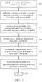
- FIG. 3 a flowchart of the operations of the controller 100 and the system executed by the processor 120 as shown in FIG. 1 is disclosed in FIG. 3 .
- the steps of the flowchart shown in FIG. 3 need not be in the exact order shown and need not be contiguous, that is, other steps can be intermediate.
- the steps of FIG. 3 are detailed in the following:
- FIG. 4 is a diagram of a controller 400 for power throttling upon a system operating on a portable device 415 according to another embodiment of the present invention.
- the controller 400 is configured within the power source 430.
- the controller 400 can be installed with a protection circuit chip for performing protection upon the power source 430. That is, the controller 400 may be configured to be near to the battery cell of power source 430. This modification also falls within the scope of the present invention.
- acquiring circuit 405, determining circuit 410, controller 400, and processor 420 are identical to those of acquiring circuit 105, determining circuit 110, controller 100, and processor 120 as shown in FIG. 1 ; further description is not described for brevity.
- aspects of the present invention may be embodied as a system, method, or computer program product. Accordingly, aspects of the present invention may take the form of an entirely hardware embodiment, an entirely software embodiment (including firmware, resident software, micro-code, etc.), or an embodiment combining software and hardware aspects that may all generally be referred to herein as a "circuit,” “module” or “system.”
- aspects of the present invention may take the form of a computer program product embodied in one or more computer readable medium(s) having computer readable program code embodied thereon.
- a computer program product for power throttling upon the system operating on the portable device (100 or 400) comprising a computer readable storage medium having computer readable program code embodied therewith is disclosed.
- the computer readable storage medium comprises computer readable program code configured to: obtain at least one characteristic information of power source (130 or 430) that is used for providing energy for the system; and, determine an available power range for the system according to the at least one characteristic information, so as to make the system control a behavior of the system according to the available power range.
- a computer program product for power throttling upon the system operating on the portable device (100 or 400) comprising a computer readable storage medium having computer readable program code embodied therewith.
- the computer readable program code comprises computer readable program code configured to: obtain at least one characteristic information of the power source (130 or 430) that is used for providing energy for the system; and dynamically adjust at least one application or dynamically disabling/enabling the at least one application according to the at least one characteristic information of the power source (130 or 430), so as to dynamically adjust a power range provided from the power source.
- the kind of the power source 130 or 430 is not a limitation of the present invention. All kinds of power sources (including batteries and adaptors) can be applied into embodiments of the present invention. For example, a low cut-off battery can be applied into the embodiments of the present invention.
- the power source 130 or 430 may be implemented by using an electrical network/grid. That is, the operation of power throttling can be used for adaptively/dynamically adjusting available power level/range for the system operating on the electrical network/grid. This example also falls within the scope of the invention.
Landscapes
- Engineering & Computer Science (AREA)
- Theoretical Computer Science (AREA)
- General Engineering & Computer Science (AREA)
- Physics & Mathematics (AREA)
- General Physics & Mathematics (AREA)
- Computer Hardware Design (AREA)
- Computing Systems (AREA)
- Computer Networks & Wireless Communication (AREA)
- Signal Processing (AREA)
- Power Sources (AREA)
- Secondary Cells (AREA)
Claims (10)
- Verfahren zur Leistungsdrosselung eines Systems, aufweisend:Erhalten mindestens einer Charakteristik einer Leistungsquelle, welche zum Bereitstellen von Energie für das System verwendet wird;Bestimmen eines verfügbaren Leistungsumfangs für das System gemäß der mindestens einen Charakteristik, um zu bewirken, dass das System ein Verhalten des Systems gemäß dem verfügbaren Leistungsumfang steuert;Aktualisieren der mindestens einen Charakteristik; undEinstellen des verfügbaren Leistungsumfangs für das System gemäß der aktualisierten mindestens einen Charakteristik, um zu bewirken, dass das System das Verhalten des Systems gemäß dem verfügbaren Leistungsumfang, der eingestellt ist, dynamisch steuert;wobeider Schritt des Bestimmens des verfügbaren Leistungsumfangs für das System umfasst:Berechnen eines verfügbaren Ausgangsstroms, der für das System gemäß der erhaltenen mindestens einen Charakteristik bereitgestellt wird, wobei der verfügbare Ausgangsstrom zu dem verfügbaren Leistungsumfang korrespondiert; undder Schritt des Einstellens des verfügbaren Leistungsumfangs für das System umfasst:Einstellen des verfügbaren Ausgangsstroms gemäß der aktualisierten mindestens einen Charakteristik;dadurch gekennzeichnet, dassder Schritt des Berechnens des verfügbaren Ausgangsstroms umfasst:Berechnen eines durchschnittlich verfügbaren Ausgangsstroms, der für das System gemäß der erhaltenen mindestens einen Charakteristik bereitgestellt wird; undBerechnen eines unmittelbar verfügbaren Ausgangsstroms, der für das System gemäß der erhaltenen mindestens einen Charakteristik bereitgestellt wird;wobei der unmittelbar verfügbare Ausgangsstrom so ausgelegt ist, dass er höher ist als der durchschnittlich verfügbare Ausgangsstrom, und das Verfahren weiter umfasst:Einstellen mindestens einer Operation des Systems, um einen ersten Anteil einer Verringerung des Ausgangsstroms, der für das System bereitgestellt wird, als Reaktion auf ein Ereignis, dass der Ausgangsstrom höher wird als der durchschnittlich verfügbare Ausgangsstrom, zu bewirken; undEinstellen der mindestens einen Operation des Systems, um einen zweiten Anteil einer Verringerung des Ausgangsstroms, der für das System bereitgestellt wird, als Reaktion auf ein Ereignis, dass der Ausgangsstrom höher wird als der unmittelbar verfügbare Ausgangsstrom, zu bewirken;wobei der erste Anteil geringer ist als der zweite Anteil.
- Verfahren gemäß Anspruch 1, wobei der Schritt des Erhaltens der mindestens einen Charakteristik umfasst:Erhalten einer Mehrzahl von Charakteristiken; undder Schritt des Bestimmens des verfügbaren Leistungsumfangs umfasst:
Bestimmen des verfügbaren Leistungsumfangs gemäß der Mehrzahl von Charakteristiken. - Verfahren gemäß Anspruch 1, wobei das Verfahren weiter aufweist:
Einstellen mindestens einer Operation des Systems, um einen Ausgangsstrom, der für das System bereitgestellt wird, als Reaktion auf ein Ereignis, dass der Ausgangsstrom höher wird als der verfügbare Ausgangsstrom, zu verringern. - Verfahren gemäß Anspruch 1, wobei das Verfahren weiter aufweist:
Einstellen mindestens einer Operation des Systems, um einen Ausgangsstrom, der für das System bereitgestellt wird, als Reaktion auf ein Ereignis, dass der Ausgangsstrom geringer wird als der verfügbare Ausgangsstrom, zu erhöhen. - Steuerung für eine Leistungsdrosselung eines Systems, aufweisend:eine Erfassungsschaltung (105, 405) zum Erhalten mindestens einer Charakteristik einer Leistungsquelle (130, 430), welche zum Bereitstellen von Energie für das System verwendet wird; undeine Bestimmungsschaltung (110, 410), die mit der Erfassungsschaltung verbunden ist, zum Bestimmen eines verfügbaren Leistungsumfangs für das System gemäß der mindestens einen Charakteristik, um zu bewirken, dass das System ein Verhalten des Systems gemäß dem verfügbaren Leistungsumfang steuert;dadurch gekennzeichnet, dassdie Bestimmungsschaltung eingerichtet ist, die Verfahrensschritte, wie in einem der Ansprüche 1 bis 4 definiert, auszuführen.
- Steuerung gemäß Anspruch 5 oder Verfahren gemäß Anspruch 1, wobei die Leistungsquelle eine Batterie und eine Schaltungsplatine, die zwischen der Batterie und dem System angeschlossen ist, aufweist; und die mindestens eine Charakteristik mindestens eins von einer Spannung der Batterie, einem Strom der Batterie, einer Temperatur der Leistungsquelle, einer inneren Impedanz der Batterie, einer Impedanz der Schaltungsplatine, einer Gesamtkapazität der Batterie, einer Restkapazität der Batterie, einem Ausdehnungskoeffizienten der Batterie und einem Schutzparameter der Batterie umfasst.
- Steuerung gemäß Anspruch 5, die innerhalb einer tragbaren Vorrichtung (115, 415) angeordnet ist, oder innerhalb der Leistungsquelle (130, 430) angeordnet ist.
- Tragbare Vorrichtung, die in der Lage ist, eine Leistungsdrosselung auszuführen, aufweisend:eine Steuerung gemäß einem der Ansprüche 5 bis 7; undeinen Prozessor zum Ausführen von Programm-Code(s), um gemäß mindestens einer Charakteristik der Leistungsquelle mindestens eine Applikation einzustellen, oder die mindestens eine Applikation zu deaktivieren/aktivieren, um einen Leistungsumfang, der von der Leistungsquelle bereitgestellt wird, einzustellen.
- Verfahren gemäß einem der Ansprüche 1 bis 4, aufweisend:
Einstellen mindestens einer Applikation oder Deaktivieren/Aktivieren der mindestens einen Applikation gemäß der mindestens einen Charakteristik der Leistungsquelle, um einen Leistungsumfang, der von der Leistungsquelle bereitgestellt wird, einzustellen. - Computer-Programmprodukt für eine Leistungsdrosselung eines Systems, das ein computer-lesbares Speichermedium mit einem damit verkörperten computer-lesbaren Programm-Code aufweist, wobei der computer-lesbare Programm-Code einen computer-lesbaren Programm-Code aufweist, der ausgelegt ist, die Verfahrensschritte, wie in Anspruch 1 oder 9 definiert, auszuführen.
Applications Claiming Priority (2)
| Application Number | Priority Date | Filing Date | Title |
|---|---|---|---|
| US201361910136P | 2013-11-29 | 2013-11-29 | |
| PCT/CN2014/092475 WO2015078408A1 (en) | 2013-11-29 | 2014-11-28 | Method and controller for power throttling upon system on portable device, corresponding portable device, and corresponding computer program products |
Publications (3)
| Publication Number | Publication Date |
|---|---|
| EP3036600A1 EP3036600A1 (de) | 2016-06-29 |
| EP3036600A4 EP3036600A4 (de) | 2017-03-15 |
| EP3036600B1 true EP3036600B1 (de) | 2019-04-03 |
Family
ID=53198392
Family Applications (1)
| Application Number | Title | Priority Date | Filing Date |
|---|---|---|---|
| EP14865747.1A Active EP3036600B1 (de) | 2013-11-29 | 2014-11-28 | Verfahren und steuerung zur leistungsdrosselung eines systems auf einer tragbaren vorrichtung, entsprechende tragbare vorrichtung und entsprechendes computerprogrammprodukt |
Country Status (5)
| Country | Link |
|---|---|
| US (1) | US10248179B2 (de) |
| EP (1) | EP3036600B1 (de) |
| JP (1) | JP6140897B2 (de) |
| CN (1) | CN105659189A (de) |
| WO (1) | WO2015078408A1 (de) |
Families Citing this family (18)
| Publication number | Priority date | Publication date | Assignee | Title |
|---|---|---|---|---|
| JP6140897B2 (ja) | 2013-11-29 | 2017-06-07 | メディアテック インコーポレイテッド | ポータブル装置上のシステムに対して電力を絞る方法及びコントローラ、対応するポータブル装置、及び対応するコンピュータプログラム製品 |
| US10114077B2 (en) | 2014-02-21 | 2018-10-30 | Mediatek Inc. | Electronic device, method, and computer readable medium having instructions capable of automatically measuring parameter(s) associated with battery cell |
| US10228751B2 (en) | 2014-08-06 | 2019-03-12 | Apple Inc. | Low power mode |
| US9647489B2 (en) | 2014-08-26 | 2017-05-09 | Apple Inc. | Brownout avoidance |
| US20170285722A1 (en) * | 2014-08-27 | 2017-10-05 | Samsung Electronics Co., Ltd. | Method for reducing battery consumption in electronic device |
| US10117196B2 (en) * | 2015-08-26 | 2018-10-30 | Qualcomm Incorporated | Dynamically configurable apparatus for operating within the current capabilities of the power source |
| GB2553196B (en) * | 2016-06-14 | 2020-10-14 | Hand Held Products Incorporated | Managing energy usage in mobile devices |
| US10306051B2 (en) | 2016-06-14 | 2019-05-28 | Hand Held Products, Inc. | Managing energy usage in mobile devices |
| US11347290B2 (en) * | 2017-08-04 | 2022-05-31 | Dell Products L.P. | Power monitor scaling for an information handling system |
| US11363133B1 (en) | 2017-12-20 | 2022-06-14 | Apple Inc. | Battery health-based power management |
| US10599199B1 (en) | 2017-12-20 | 2020-03-24 | Apple Inc. | Systems and methods for power management at device shutdown |
| US10817307B1 (en) | 2017-12-20 | 2020-10-27 | Apple Inc. | API behavior modification based on power source health |
| CN109960395B (zh) * | 2018-10-15 | 2021-06-08 | 华为技术有限公司 | 资源调度方法和计算机设备 |
| TWI770856B (zh) * | 2021-03-04 | 2022-07-11 | 華碩電腦股份有限公司 | 可攜式計算裝置 |
| US20240338067A1 (en) * | 2023-04-06 | 2024-10-10 | Microsoft Technology Licensing, Llc | Enhanced electricity limitation enforcement during application runtime |
| CN116679816B (zh) * | 2023-08-03 | 2024-02-09 | 深圳市蓝晨科技股份有限公司 | 一种系统功耗的调整方法、系统、终端及存储介质 |
| CN117087497B (zh) * | 2023-08-17 | 2024-03-08 | 广州巨湾技研有限公司 | 动力电池系统的功率控制方法、动力电池系统及存储介质 |
| US20250251767A1 (en) * | 2024-02-06 | 2025-08-07 | Hewlett Packard Enterprise Development Lp | Computer implemented method of monitoring power and adjusting component performance |
Citations (1)
| Publication number | Priority date | Publication date | Assignee | Title |
|---|---|---|---|---|
| US20130254579A1 (en) * | 2012-03-23 | 2013-09-26 | Qualcomm Incorporated | System and method for managing electrical current in a portable computing device |
Family Cites Families (27)
| Publication number | Priority date | Publication date | Assignee | Title |
|---|---|---|---|---|
| US6472848B2 (en) * | 2001-01-18 | 2002-10-29 | Hewlett-Packard Company | Reducing battery discharge current by throttling CPU power |
| JP2003202935A (ja) * | 2002-01-08 | 2003-07-18 | Mitsubishi Electric Corp | 電力管理方式及び電力管理方法 |
| JP3692089B2 (ja) | 2002-04-02 | 2005-09-07 | 株式会社東芝 | 消費電力制御方法及び情報処理装置 |
| KR20040103991A (ko) * | 2003-06-02 | 2004-12-10 | 삼성전자주식회사 | 컴퓨터 및 그 제어방법 |
| JP2006331107A (ja) * | 2005-05-26 | 2006-12-07 | Matsushita Electric Ind Co Ltd | 電力管理回路、及び電子回路 |
| US20080028246A1 (en) * | 2006-07-31 | 2008-01-31 | Witham Timothy D | Self-monitoring and self-adjusting power consumption computer control system |
| CN101122815B (zh) * | 2006-08-11 | 2010-05-12 | 宏碁股份有限公司 | 用于膝上型电脑装置的电源管理系统及其管理方法 |
| US7689851B2 (en) * | 2006-10-27 | 2010-03-30 | Hewlett-Packard Development Company, L.P. | Limiting power state changes to a processor of a computer device |
| US20080200220A1 (en) * | 2007-02-16 | 2008-08-21 | Jackson Bruce K | Methods and devices for limiting battery power consumption in a wireless communication device |
| US7430675B2 (en) * | 2007-02-16 | 2008-09-30 | Apple Inc. | Anticipatory power management for battery-powered electronic device |
| CN101349713B (zh) | 2007-07-20 | 2011-07-13 | 奇瑞汽车股份有限公司 | 混合动力汽车电池内阻检测方法 |
| US8271056B2 (en) | 2008-01-17 | 2012-09-18 | International Business Machines Corporation | Managing battery needs in a portable device |
| CN101339214B (zh) | 2008-08-19 | 2010-11-17 | 河北天翼科贸发展有限公司 | 蓄电池内阻测量方法 |
| KR101081087B1 (ko) | 2009-07-14 | 2011-11-07 | 현대자동차주식회사 | 차량용 고전압 배터리의 셀 내부 저항 측정 방법 |
| US8421467B2 (en) | 2009-11-19 | 2013-04-16 | Valence Technology, Inc. | Battery insulation resistance measurement methods, insulation resistance measurement methods, insulation resistance determination apparatuses, and articles of manufacture |
| EP2403183B1 (de) * | 2010-06-30 | 2013-01-02 | Alcatel Lucent | Verfahren zur Verwaltung des Stromverbrauchs in einem Kommunikationsnetzwerk |
| CN101943942B (zh) * | 2010-08-24 | 2013-06-05 | 鸿富锦精密工业(深圳)有限公司 | 具有睡眠功能的电子装置及唤醒电子装置的方法 |
| US20120210150A1 (en) * | 2011-02-10 | 2012-08-16 | Alcatel-Lucent Usa Inc. | Method And Apparatus Of Smart Power Management For Mobile Communication Terminals |
| US20120239949A1 (en) | 2011-03-14 | 2012-09-20 | Research In Motion Limited | Electronic device and method for application and profile sensitive battery power management |
| CN202383263U (zh) | 2011-12-14 | 2012-08-15 | 云南电网公司临沧供电局 | 一种直流系统蓄电池性能的在线监测装置 |
| US20130320880A1 (en) * | 2012-05-16 | 2013-12-05 | James T. Walker | Rms responding voltage converter for led lights |
| CN102854471B (zh) | 2012-09-06 | 2016-01-13 | 北京百纳威尔科技有限公司 | 电池电量计量方法及计量装置 |
| CN203178367U (zh) | 2012-12-28 | 2013-09-04 | 深圳市沃特玛电池有限公司 | 电池分容柜的内阻测量电路 |
| CN105979103B (zh) | 2013-02-05 | 2020-05-12 | 北京奇虎科技有限公司 | 便携式电子产品的电池电量保障方法、设备及移动终端 |
| CN103198543B (zh) | 2013-03-07 | 2015-06-24 | 李凯 | 实时获知锁的电池状态的方法和系统 |
| JP6140897B2 (ja) | 2013-11-29 | 2017-06-07 | メディアテック インコーポレイテッド | ポータブル装置上のシステムに対して電力を絞る方法及びコントローラ、対応するポータブル装置、及び対応するコンピュータプログラム製品 |
| US10114077B2 (en) | 2014-02-21 | 2018-10-30 | Mediatek Inc. | Electronic device, method, and computer readable medium having instructions capable of automatically measuring parameter(s) associated with battery cell |
-
2014
- 2014-11-28 JP JP2016533598A patent/JP6140897B2/ja active Active
- 2014-11-28 CN CN201480056308.6A patent/CN105659189A/zh active Pending
- 2014-11-28 EP EP14865747.1A patent/EP3036600B1/de active Active
- 2014-11-28 WO PCT/CN2014/092475 patent/WO2015078408A1/en not_active Ceased
- 2014-11-28 US US15/037,684 patent/US10248179B2/en active Active
Patent Citations (1)
| Publication number | Priority date | Publication date | Assignee | Title |
|---|---|---|---|---|
| US20130254579A1 (en) * | 2012-03-23 | 2013-09-26 | Qualcomm Incorporated | System and method for managing electrical current in a portable computing device |
Also Published As
| Publication number | Publication date |
|---|---|
| US20160299551A1 (en) | 2016-10-13 |
| US10248179B2 (en) | 2019-04-02 |
| JP2016541064A (ja) | 2016-12-28 |
| CN105659189A (zh) | 2016-06-08 |
| EP3036600A4 (de) | 2017-03-15 |
| JP6140897B2 (ja) | 2017-06-07 |
| EP3036600A1 (de) | 2016-06-29 |
| WO2015078408A1 (en) | 2015-06-04 |
Similar Documents
| Publication | Publication Date | Title |
|---|---|---|
| EP3036600B1 (de) | Verfahren und steuerung zur leistungsdrosselung eines systems auf einer tragbaren vorrichtung, entsprechende tragbare vorrichtung und entsprechendes computerprogrammprodukt | |
| US20220043067A1 (en) | Charging method and device, charging system, electronic equipment and storage medium | |
| TWI448889B (zh) | 具有動態調整運作模式機制之電子裝置及其方法 | |
| EP3211750B1 (de) | Verfahren und system zur dynamischen anpassung von batterieunterspannungsschutz | |
| CN106992326B (zh) | 一种充电控制方法、装置及电子设备 | |
| US20130124892A1 (en) | Electronic device and power management method thereof | |
| CN103150235B (zh) | 一种自动保存易失性存储器中数据的方法及移动终端 | |
| CN103858070A (zh) | 一种关机门限电压的调节方法、开机方法及其电子设备 | |
| CN105449757A (zh) | 防止充电过程中适配器或移动电源断开的方法及装置 | |
| CN105739668A (zh) | 一种笔记本电脑的电源管理方法及电源管理系统 | |
| CN107356881A (zh) | 一种终端的控制方法、装置及终端 | |
| CN103296638A (zh) | 电子设备以及应用于电子设备的掉电保护装置及方法 | |
| CN103915864B (zh) | 具有电源控制功能的电子装置 | |
| US20160299179A1 (en) | Scheme capable of estimating available power range according to extra power range and employing available power range as reference of performing power throttling upon a system | |
| US8782444B2 (en) | Circuit protection system and method for a circuit utilizing chip type power supply | |
| EP2479640B1 (de) | Tragbares elektronisches Gerät und Verfahren zur Anpassung von dessen Systemleistung | |
| CN109521858B (zh) | 一种计算机供电控制方法及装置 | |
| EP4043892A1 (de) | Verfahren und vorrichtung zur funktionsprüfung von adapter, prüfvorrichtung und speichermedium | |
| CN110148992B (zh) | 一种充电控制方法、终端设备及存储介质 | |
| WO2017092226A1 (zh) | 一种充电电流调节方法及移动终端 | |
| CN115211011A (zh) | 供电方法、装置、电子设备和可读存储介质 | |
| CN110425704A (zh) | 一种压缩机下限频率控制方法、装置及空调器 | |
| US20170093181A1 (en) | Charging control method and apparatus, terminal and computer storage medium | |
| CN103605539A (zh) | 单片机系统时钟频率控制方法及系统 | |
| KR102800822B1 (ko) | 배터리를 충전하는 방법 및 그 방법을 적용한 전자 장치 |
Legal Events
| Date | Code | Title | Description |
|---|---|---|---|
| PUAI | Public reference made under article 153(3) epc to a published international application that has entered the european phase |
Free format text: ORIGINAL CODE: 0009012 |
|
| 17P | Request for examination filed |
Effective date: 20160322 |
|
| AK | Designated contracting states |
Kind code of ref document: A1 Designated state(s): AL AT BE BG CH CY CZ DE DK EE ES FI FR GB GR HR HU IE IS IT LI LT LU LV MC MK MT NL NO PL PT RO RS SE SI SK SM TR |
|
| AX | Request for extension of the european patent |
Extension state: BA ME |
|
| DAX | Request for extension of the european patent (deleted) | ||
| A4 | Supplementary search report drawn up and despatched |
Effective date: 20170214 |
|
| RIC1 | Information provided on ipc code assigned before grant |
Ipc: H04W 52/02 20090101ALI20170208BHEP Ipc: G06F 1/32 20060101AFI20170208BHEP |
|
| GRAP | Despatch of communication of intention to grant a patent |
Free format text: ORIGINAL CODE: EPIDOSNIGR1 |
|
| STAA | Information on the status of an ep patent application or granted ep patent |
Free format text: STATUS: GRANT OF PATENT IS INTENDED |
|
| INTG | Intention to grant announced |
Effective date: 20190109 |
|
| GRAS | Grant fee paid |
Free format text: ORIGINAL CODE: EPIDOSNIGR3 |
|
| GRAA | (expected) grant |
Free format text: ORIGINAL CODE: 0009210 |
|
| STAA | Information on the status of an ep patent application or granted ep patent |
Free format text: STATUS: THE PATENT HAS BEEN GRANTED |
|
| AK | Designated contracting states |
Kind code of ref document: B1 Designated state(s): AL AT BE BG CH CY CZ DE DK EE ES FI FR GB GR HR HU IE IS IT LI LT LU LV MC MK MT NL NO PL PT RO RS SE SI SK SM TR |
|
| RAP1 | Party data changed (applicant data changed or rights of an application transferred) |
Owner name: MEDIATEK INC. |
|
| REG | Reference to a national code |
Ref country code: GB Ref legal event code: FG4D |
|
| REG | Reference to a national code |
Ref country code: CH Ref legal event code: EP Ref country code: AT Ref legal event code: REF Ref document number: 1116528 Country of ref document: AT Kind code of ref document: T Effective date: 20190415 |
|
| REG | Reference to a national code |
Ref country code: DE Ref legal event code: R096 Ref document number: 602014044192 Country of ref document: DE |
|
| REG | Reference to a national code |
Ref country code: IE Ref legal event code: FG4D |
|
| REG | Reference to a national code |
Ref country code: NL Ref legal event code: MP Effective date: 20190403 |
|
| REG | Reference to a national code |
Ref country code: LT Ref legal event code: MG4D |
|
| REG | Reference to a national code |
Ref country code: AT Ref legal event code: MK05 Ref document number: 1116528 Country of ref document: AT Kind code of ref document: T Effective date: 20190403 |
|
| PG25 | Lapsed in a contracting state [announced via postgrant information from national office to epo] |
Ref country code: NL Free format text: LAPSE BECAUSE OF FAILURE TO SUBMIT A TRANSLATION OF THE DESCRIPTION OR TO PAY THE FEE WITHIN THE PRESCRIBED TIME-LIMIT Effective date: 20190403 |
|
| PG25 | Lapsed in a contracting state [announced via postgrant information from national office to epo] |
Ref country code: LT Free format text: LAPSE BECAUSE OF FAILURE TO SUBMIT A TRANSLATION OF THE DESCRIPTION OR TO PAY THE FEE WITHIN THE PRESCRIBED TIME-LIMIT Effective date: 20190403 Ref country code: FI Free format text: LAPSE BECAUSE OF FAILURE TO SUBMIT A TRANSLATION OF THE DESCRIPTION OR TO PAY THE FEE WITHIN THE PRESCRIBED TIME-LIMIT Effective date: 20190403 Ref country code: SE Free format text: LAPSE BECAUSE OF FAILURE TO SUBMIT A TRANSLATION OF THE DESCRIPTION OR TO PAY THE FEE WITHIN THE PRESCRIBED TIME-LIMIT Effective date: 20190403 Ref country code: NO Free format text: LAPSE BECAUSE OF FAILURE TO SUBMIT A TRANSLATION OF THE DESCRIPTION OR TO PAY THE FEE WITHIN THE PRESCRIBED TIME-LIMIT Effective date: 20190703 Ref country code: HR Free format text: LAPSE BECAUSE OF FAILURE TO SUBMIT A TRANSLATION OF THE DESCRIPTION OR TO PAY THE FEE WITHIN THE PRESCRIBED TIME-LIMIT Effective date: 20190403 Ref country code: CZ Free format text: LAPSE BECAUSE OF FAILURE TO SUBMIT A TRANSLATION OF THE DESCRIPTION OR TO PAY THE FEE WITHIN THE PRESCRIBED TIME-LIMIT Effective date: 20190403 Ref country code: PT Free format text: LAPSE BECAUSE OF FAILURE TO SUBMIT A TRANSLATION OF THE DESCRIPTION OR TO PAY THE FEE WITHIN THE PRESCRIBED TIME-LIMIT Effective date: 20190803 Ref country code: ES Free format text: LAPSE BECAUSE OF FAILURE TO SUBMIT A TRANSLATION OF THE DESCRIPTION OR TO PAY THE FEE WITHIN THE PRESCRIBED TIME-LIMIT Effective date: 20190403 Ref country code: AL Free format text: LAPSE BECAUSE OF FAILURE TO SUBMIT A TRANSLATION OF THE DESCRIPTION OR TO PAY THE FEE WITHIN THE PRESCRIBED TIME-LIMIT Effective date: 20190403 |
|
| PG25 | Lapsed in a contracting state [announced via postgrant information from national office to epo] |
Ref country code: GR Free format text: LAPSE BECAUSE OF FAILURE TO SUBMIT A TRANSLATION OF THE DESCRIPTION OR TO PAY THE FEE WITHIN THE PRESCRIBED TIME-LIMIT Effective date: 20190704 Ref country code: BG Free format text: LAPSE BECAUSE OF FAILURE TO SUBMIT A TRANSLATION OF THE DESCRIPTION OR TO PAY THE FEE WITHIN THE PRESCRIBED TIME-LIMIT Effective date: 20190703 Ref country code: RS Free format text: LAPSE BECAUSE OF FAILURE TO SUBMIT A TRANSLATION OF THE DESCRIPTION OR TO PAY THE FEE WITHIN THE PRESCRIBED TIME-LIMIT Effective date: 20190403 Ref country code: LV Free format text: LAPSE BECAUSE OF FAILURE TO SUBMIT A TRANSLATION OF THE DESCRIPTION OR TO PAY THE FEE WITHIN THE PRESCRIBED TIME-LIMIT Effective date: 20190403 Ref country code: PL Free format text: LAPSE BECAUSE OF FAILURE TO SUBMIT A TRANSLATION OF THE DESCRIPTION OR TO PAY THE FEE WITHIN THE PRESCRIBED TIME-LIMIT Effective date: 20190403 |
|
| PG25 | Lapsed in a contracting state [announced via postgrant information from national office to epo] |
Ref country code: IS Free format text: LAPSE BECAUSE OF FAILURE TO SUBMIT A TRANSLATION OF THE DESCRIPTION OR TO PAY THE FEE WITHIN THE PRESCRIBED TIME-LIMIT Effective date: 20190803 Ref country code: AT Free format text: LAPSE BECAUSE OF FAILURE TO SUBMIT A TRANSLATION OF THE DESCRIPTION OR TO PAY THE FEE WITHIN THE PRESCRIBED TIME-LIMIT Effective date: 20190403 |
|
| REG | Reference to a national code |
Ref country code: DE Ref legal event code: R097 Ref document number: 602014044192 Country of ref document: DE |
|
| PG25 | Lapsed in a contracting state [announced via postgrant information from national office to epo] |
Ref country code: EE Free format text: LAPSE BECAUSE OF FAILURE TO SUBMIT A TRANSLATION OF THE DESCRIPTION OR TO PAY THE FEE WITHIN THE PRESCRIBED TIME-LIMIT Effective date: 20190403 Ref country code: DK Free format text: LAPSE BECAUSE OF FAILURE TO SUBMIT A TRANSLATION OF THE DESCRIPTION OR TO PAY THE FEE WITHIN THE PRESCRIBED TIME-LIMIT Effective date: 20190403 Ref country code: SK Free format text: LAPSE BECAUSE OF FAILURE TO SUBMIT A TRANSLATION OF THE DESCRIPTION OR TO PAY THE FEE WITHIN THE PRESCRIBED TIME-LIMIT Effective date: 20190403 Ref country code: RO Free format text: LAPSE BECAUSE OF FAILURE TO SUBMIT A TRANSLATION OF THE DESCRIPTION OR TO PAY THE FEE WITHIN THE PRESCRIBED TIME-LIMIT Effective date: 20190403 |
|
| PLBE | No opposition filed within time limit |
Free format text: ORIGINAL CODE: 0009261 |
|
| STAA | Information on the status of an ep patent application or granted ep patent |
Free format text: STATUS: NO OPPOSITION FILED WITHIN TIME LIMIT |
|
| PG25 | Lapsed in a contracting state [announced via postgrant information from national office to epo] |
Ref country code: SM Free format text: LAPSE BECAUSE OF FAILURE TO SUBMIT A TRANSLATION OF THE DESCRIPTION OR TO PAY THE FEE WITHIN THE PRESCRIBED TIME-LIMIT Effective date: 20190403 Ref country code: IT Free format text: LAPSE BECAUSE OF FAILURE TO SUBMIT A TRANSLATION OF THE DESCRIPTION OR TO PAY THE FEE WITHIN THE PRESCRIBED TIME-LIMIT Effective date: 20190403 |
|
| 26N | No opposition filed |
Effective date: 20200106 |
|
| PG25 | Lapsed in a contracting state [announced via postgrant information from national office to epo] |
Ref country code: TR Free format text: LAPSE BECAUSE OF FAILURE TO SUBMIT A TRANSLATION OF THE DESCRIPTION OR TO PAY THE FEE WITHIN THE PRESCRIBED TIME-LIMIT Effective date: 20190403 |
|
| PG25 | Lapsed in a contracting state [announced via postgrant information from national office to epo] |
Ref country code: SI Free format text: LAPSE BECAUSE OF FAILURE TO SUBMIT A TRANSLATION OF THE DESCRIPTION OR TO PAY THE FEE WITHIN THE PRESCRIBED TIME-LIMIT Effective date: 20190403 |
|
| REG | Reference to a national code |
Ref country code: CH Ref legal event code: PL |
|
| PG25 | Lapsed in a contracting state [announced via postgrant information from national office to epo] |
Ref country code: LI Free format text: LAPSE BECAUSE OF NON-PAYMENT OF DUE FEES Effective date: 20191130 Ref country code: MC Free format text: LAPSE BECAUSE OF FAILURE TO SUBMIT A TRANSLATION OF THE DESCRIPTION OR TO PAY THE FEE WITHIN THE PRESCRIBED TIME-LIMIT Effective date: 20190403 Ref country code: CH Free format text: LAPSE BECAUSE OF NON-PAYMENT OF DUE FEES Effective date: 20191130 Ref country code: LU Free format text: LAPSE BECAUSE OF NON-PAYMENT OF DUE FEES Effective date: 20191128 |
|
| REG | Reference to a national code |
Ref country code: BE Ref legal event code: MM Effective date: 20191130 |
|
| PG25 | Lapsed in a contracting state [announced via postgrant information from national office to epo] |
Ref country code: IE Free format text: LAPSE BECAUSE OF NON-PAYMENT OF DUE FEES Effective date: 20191128 |
|
| PG25 | Lapsed in a contracting state [announced via postgrant information from national office to epo] |
Ref country code: BE Free format text: LAPSE BECAUSE OF NON-PAYMENT OF DUE FEES Effective date: 20191130 |
|
| PG25 | Lapsed in a contracting state [announced via postgrant information from national office to epo] |
Ref country code: CY Free format text: LAPSE BECAUSE OF FAILURE TO SUBMIT A TRANSLATION OF THE DESCRIPTION OR TO PAY THE FEE WITHIN THE PRESCRIBED TIME-LIMIT Effective date: 20190403 |
|
| PG25 | Lapsed in a contracting state [announced via postgrant information from national office to epo] |
Ref country code: MT Free format text: LAPSE BECAUSE OF FAILURE TO SUBMIT A TRANSLATION OF THE DESCRIPTION OR TO PAY THE FEE WITHIN THE PRESCRIBED TIME-LIMIT Effective date: 20190403 Ref country code: HU Free format text: LAPSE BECAUSE OF FAILURE TO SUBMIT A TRANSLATION OF THE DESCRIPTION OR TO PAY THE FEE WITHIN THE PRESCRIBED TIME-LIMIT; INVALID AB INITIO Effective date: 20141128 |
|
| PG25 | Lapsed in a contracting state [announced via postgrant information from national office to epo] |
Ref country code: MK Free format text: LAPSE BECAUSE OF FAILURE TO SUBMIT A TRANSLATION OF THE DESCRIPTION OR TO PAY THE FEE WITHIN THE PRESCRIBED TIME-LIMIT Effective date: 20190403 |
|
| P01 | Opt-out of the competence of the unified patent court (upc) registered |
Effective date: 20230607 |
|
| PGFP | Annual fee paid to national office [announced via postgrant information from national office to epo] |
Ref country code: FR Payment date: 20250930 Year of fee payment: 12 |
|
| PGFP | Annual fee paid to national office [announced via postgrant information from national office to epo] |
Ref country code: DE Payment date: 20250930 Year of fee payment: 12 |
|
| PGFP | Annual fee paid to national office [announced via postgrant information from national office to epo] |
Ref country code: GB Payment date: 20251001 Year of fee payment: 12 |