EP3036019B1 - Snowboard with modified rails and edges - Google Patents
Snowboard with modified rails and edges Download PDFInfo
- Publication number
- EP3036019B1 EP3036019B1 EP14838724.4A EP14838724A EP3036019B1 EP 3036019 B1 EP3036019 B1 EP 3036019B1 EP 14838724 A EP14838724 A EP 14838724A EP 3036019 B1 EP3036019 B1 EP 3036019B1
- Authority
- EP
- European Patent Office
- Prior art keywords
- board
- snow
- peripheral edge
- rails
- rail
- Prior art date
- Legal status (The legal status is an assumption and is not a legal conclusion. Google has not performed a legal analysis and makes no representation as to the accuracy of the status listed.)
- Active
Links
- 230000002093 peripheral effect Effects 0.000 claims description 30
- 230000027455 binding Effects 0.000 claims description 10
- 238000009739 binding Methods 0.000 claims description 10
- 239000000463 material Substances 0.000 claims description 9
- 238000004519 manufacturing process Methods 0.000 claims description 7
- 230000007423 decrease Effects 0.000 claims description 6
- 238000000034 method Methods 0.000 description 8
- 230000001133 acceleration Effects 0.000 description 3
- 230000008901 benefit Effects 0.000 description 3
- 239000011230 binding agent Substances 0.000 description 2
- 238000005056 compaction Methods 0.000 description 2
- 230000003247 decreasing effect Effects 0.000 description 2
- 238000013551 empirical research Methods 0.000 description 2
- 239000011152 fibreglass Substances 0.000 description 2
- 239000002184 metal Substances 0.000 description 2
- 239000004033 plastic Substances 0.000 description 2
- 229920003023 plastic Polymers 0.000 description 2
- 230000000630 rising effect Effects 0.000 description 2
- 239000002023 wood Substances 0.000 description 2
- 239000004698 Polyethylene Substances 0.000 description 1
- 230000009471 action Effects 0.000 description 1
- 238000007792 addition Methods 0.000 description 1
- 239000000956 alloy Substances 0.000 description 1
- 229910045601 alloy Inorganic materials 0.000 description 1
- 235000014121 butter Nutrition 0.000 description 1
- 230000008859 change Effects 0.000 description 1
- 230000006378 damage Effects 0.000 description 1
- 230000009977 dual effect Effects 0.000 description 1
- 230000000694 effects Effects 0.000 description 1
- 239000011121 hardwood Substances 0.000 description 1
- 230000000977 initiatory effect Effects 0.000 description 1
- 230000003993 interaction Effects 0.000 description 1
- 238000012986 modification Methods 0.000 description 1
- 230000004048 modification Effects 0.000 description 1
- -1 polyethylene Polymers 0.000 description 1
- 229920000573 polyethylene Polymers 0.000 description 1
- 238000005381 potential energy Methods 0.000 description 1
- 230000008569 process Effects 0.000 description 1
- 230000004044 response Effects 0.000 description 1
- 230000007704 transition Effects 0.000 description 1
- XLYOFNOQVPJJNP-UHFFFAOYSA-N water Substances O XLYOFNOQVPJJNP-UHFFFAOYSA-N 0.000 description 1
Images


Classifications
-
- A—HUMAN NECESSITIES
- A63—SPORTS; GAMES; AMUSEMENTS
- A63C—SKATES; SKIS; ROLLER SKATES; DESIGN OR LAYOUT OF COURTS, RINKS OR THE LIKE
- A63C5/00—Skis or snowboards
- A63C5/04—Structure of the surface thereof
- A63C5/044—Structure of the surface thereof of the running sole
-
- A—HUMAN NECESSITIES
- A63—SPORTS; GAMES; AMUSEMENTS
- A63C—SKATES; SKIS; ROLLER SKATES; DESIGN OR LAYOUT OF COURTS, RINKS OR THE LIKE
- A63C5/00—Skis or snowboards
- A63C5/03—Mono skis; Snowboards
-
- A—HUMAN NECESSITIES
- A63—SPORTS; GAMES; AMUSEMENTS
- A63C—SKATES; SKIS; ROLLER SKATES; DESIGN OR LAYOUT OF COURTS, RINKS OR THE LIKE
- A63C10/00—Snowboard bindings
- A63C10/02—Snowboard bindings characterised by details of the shoe holders
-
- A—HUMAN NECESSITIES
- A63—SPORTS; GAMES; AMUSEMENTS
- A63C—SKATES; SKIS; ROLLER SKATES; DESIGN OR LAYOUT OF COURTS, RINKS OR THE LIKE
- A63C5/00—Skis or snowboards
- A63C5/03—Mono skis; Snowboards
- A63C5/031—Snow-ski boards with two or more runners or skis connected together by a rider-supporting platform
-
- A—HUMAN NECESSITIES
- A63—SPORTS; GAMES; AMUSEMENTS
- A63C—SKATES; SKIS; ROLLER SKATES; DESIGN OR LAYOUT OF COURTS, RINKS OR THE LIKE
- A63C5/00—Skis or snowboards
- A63C5/04—Structure of the surface thereof
- A63C5/0417—Structure of the surface thereof with fins or longitudinal protrusions on the running sole
-
- A—HUMAN NECESSITIES
- A63—SPORTS; GAMES; AMUSEMENTS
- A63C—SKATES; SKIS; ROLLER SKATES; DESIGN OR LAYOUT OF COURTS, RINKS OR THE LIKE
- A63C5/00—Skis or snowboards
- A63C5/04—Structure of the surface thereof
- A63C5/0422—Longitudinal guiding grooves
-
- A—HUMAN NECESSITIES
- A63—SPORTS; GAMES; AMUSEMENTS
- A63C—SKATES; SKIS; ROLLER SKATES; DESIGN OR LAYOUT OF COURTS, RINKS OR THE LIKE
- A63C5/00—Skis or snowboards
- A63C5/04—Structure of the surface thereof
- A63C5/048—Structure of the surface thereof of the edges
-
- A—HUMAN NECESSITIES
- A63—SPORTS; GAMES; AMUSEMENTS
- A63C—SKATES; SKIS; ROLLER SKATES; DESIGN OR LAYOUT OF COURTS, RINKS OR THE LIKE
- A63C5/00—Skis or snowboards
- A63C5/04—Structure of the surface thereof
- A63C5/056—Materials for the running sole
-
- Y—GENERAL TAGGING OF NEW TECHNOLOGICAL DEVELOPMENTS; GENERAL TAGGING OF CROSS-SECTIONAL TECHNOLOGIES SPANNING OVER SEVERAL SECTIONS OF THE IPC; TECHNICAL SUBJECTS COVERED BY FORMER USPC CROSS-REFERENCE ART COLLECTIONS [XRACs] AND DIGESTS
- Y10—TECHNICAL SUBJECTS COVERED BY FORMER USPC
- Y10T—TECHNICAL SUBJECTS COVERED BY FORMER US CLASSIFICATION
- Y10T29/00—Metal working
- Y10T29/49—Method of mechanical manufacture
- Y10T29/49826—Assembling or joining
Definitions
- the systems and methods described herein relate to sporting equipment. Specifically, snowboards and other systems and methods for enabling motion of a person across a surface of snow.
- snowboards travel differently than skis and sleds.
- snowboards allow users to lift up on or tilt onto an edge of the board and use the force of the board's edge against the snow surface to tum direction. This type of turning is called carving and it essentially allows the skilled snowboarder to make tight radius turns.
- the snowboarder positions his or her feet transverse to the longitudinal axis of the board. This means that the snowboarder must lean forward or backwards to tilt the board on to one of its edges.
- US 5,340,144 discloses a vehicle for travel on snow or water consisting of an elongated main member having a top and a bottom surface with a venturi effect.
- First and second runners extend lengthwise and downwardly along opposed edges of the bottom surface from a point spaced rearwardly of the front end of the member to a point spaced forwardly of the rear end of the member.
- the runners and bottom surface define the venturi section that tapers inwardly to a narrow throat in the vicinity of the middle of the member and then tapers outwardly.
- Elongated side cuts are provided to the elongated outside surfaces of the board, the side cuts creating a surface which is narrower in width between the front and the back of the surface.
- US 2009/0102161 discloses a snowboard or ski or the like comprising a base body having at least one edge, a top surface and a bottom surface; wherein the edge comprises at least one channel formed therein to provide two or more edge elements to contact a medium during use.
- Described herein are a system and method for supporting a person and enabling motion of a person across a surface of snow while satisfying the countervailing requirements of increasing surface area for weight-carrying capacity on soft snow and reducing the opposing forces, like for example drag and friction, in hard snow. More specifically, according to the invention there is provided a snowboard according to claim 1 and a method of manufacturing a snowboard according to claim 12.
- the system is designed to support the weight of the user and to provide motion across the surface of snow.
- the weight-carrying capacity of snow increases with compaction.
- Soft, uncompact snow has a lower weight-carrying capacity than hard, compact snow.
- the area of contact between the system and the snow is calculated by multiplying the width of contact between the system and the snow by the length of contact between the system and the snow.
- the system carries the weight of the user by transferring the weight to the snow surface across the area of contact.
- the maximum operating speed of the system is, in part, determined by magnitude of opposing forces that occur at the area of contact between the system and the snow surface.
- the opposing forces may be generated by friction, drag or other forces that oppose the primary direction of travel while the system is in use. Opposing forces have a negative impact on the maximum speed of the system.
- a conventional system that is designed for soft-snow causes unnecessary drag and friction when operated on hard snow.
- the user when operating a conventional system, the user must be careful not to operate the system in a substantially flat position.
- a flat position is characterized by two opposing edges of the system touching the snow simultaneously. Often, the two edges are oriented perpendicular to the primary direction of travel.
- the snowboards described here address the countervailing requirements of increasing area for weight-carrying capacity on soft snow and reducing the opposing forces in hard snow. Moreover, these snowboards reduce the likelihood of unintentionally catching an edge in the snow.
- the system and methods disclosed herein support the weight of the user and enable motion at a high maximum speed on snow while satisfying the countervailing requirements of increasing weight-carrying capacity reducing opposing forces.
- the systems includes a contoured lower surface that sinks lower in soft snow and rises higher in hard snow.
- the lower surface has at least two rails and a recessed region, which provide additional surface area for transferring weight to the snow. The amount of area contacting the snow adjusts based on, in part, the rider's speed, weight and the current snow conditions.
- the rails on the lower surface are sloped up toward the periphery of the system, which lifts the edges up from the snow surface and thereby reduces the likelihood of unintentionally catching an edge in the snow.
- the systems and methods described herein include, among other things, snowboards having a board with an upper surface and a lower surface and a first and second end. Typically, both the first and second ends are curved upward, to lift the ends of the board off the surface of the snow, as commonly done with snowboards.
- the upper surface has locations for a first binding and a second binding to allow the bindings to be arranged transverse to a longitudinal axis extending through the first and second ends.
- the lower surface has a first and a second rail extending along the longitudinal axis and being separated by a recess extending along the longitudinal axis.
- the rails and the recess all have a width, as measured transverse to the longitudinal axis of the board.
- the width of the recess is typically, but not necessarily, greater than the width of each respective rail and the first and second rails and the recess extend across the width of the bottom surface and substantially the length of the bottom surface of the board.
- the snowboard may have first and second rails that have respective interior shoulder walls having an at least 30° inclination from an axis parallel to a beam of the board. Further optionally, the snowboard may have first and second rails have a width substantially equal to one quarter the width of the bottom surface of the board.
- the snowboard may have one or more bindings for gripping a boot of a rider, and the binding may be arranged to position a heel of the boot over one rail and a toe of the boot over a different rail.
- the snowboard may have first and second rails that have surfaces for contacting the snow, the surfaces being tapered to narrow in thickness from the recess to the peripheral edge of the board.
- the peripheral edge of the board when the board rests against a flat surface, the peripheral edge of the board is raised above the flat surface.
- the peripheral edge may be raised between about 1 mm and 8 mm above the flat surface, or any other suitable distance.
- the snowboard may have first and second rails that comprise modular bodies for being secured to the bottom surface of the board.
- the snowboard may have first and second rails that comprise rails integrally formed as part of the bottom surface of the board.
- the snowboard under typical operating conditions, has rails with a width selected to support the weight of a user, and thereby have the recessed surface apply a force less than the weight of the user, which may include no substantial force, to the surface of the snow, such that the center of the board applies little or no force to the surface of the snow and frictional forces generated against the center of the board are reduced or eliminated.
- the snowboard has a bottom surface having two rails.
- the two rails run the length, or substantially the length, of the snow board and these two rails are separated by a recess, so that the two rails are arranged to place one along each side of the snowboard.
- the rails have a bottom surface that contacts the snow. Under certain operating conditions, such as when the snow is compact and firm enough to prevent or reduce the rails from sinking more than a few millimeters into the snow, the snowboard moves over the snow with the rails in contact with the snow surface and the recessed portion of the board spaced away from the compact snow surface.
- the rails may have a tapered surface.
- the taper may progress from the interior side of the rail adjacent to the recess toward the peripheral edge of the board. The taper spaces the peripheral edge of the board away from a flat surface on which the rails may rest.
- the tapered surfaces are examples of a contoured lower surface having dual rails.
- the contoured lower surface may sink lower in soft snow and ride higher in hard snow.
- the amount of area contacting the snow adjusts based on, in part, the rider's speed, weight and the snow conditions.
- the rails on the lower surface may optionally be sloped up toward the periphery of the board and may reduce the likelihood of unintentionally catching an edge in the snow, and thereby improve stability.
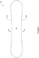
- Figure 1 depicts a prior art snowboard 100 designed to support the weight of a person and to enable motion on snow.
- the snowboard 100 contains at least one rigid element, wherein each rigid element has an upper surface (not shown), a lower surface 203 and one or more stiffened peripheral edges 101(a) and (b). Edges 101(a) and (b) are located on left and right ends and, in some embodiments, may line the entire periphery of the system. Edges 101 may be made of metal, alloy or any other suitable material.
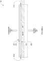
- FIG. 2 depicts a cross-sectional detail of the prior art snowboard of Figure 1 .
- the snowboard 100 has an upper surface 201, a lower surface 203, and a plurality of inner-layers 202 positioned between the upper surface 201 and lower surface 203 .
- Edges 101 (a) and (b) are located on left and right ends, respectively.
- the lower surface 203 rests on the snow surface 204 .
- the downward force 206 is transferred through the system 100 and is balanced by the normal force 207 .
- Upper surface 201 may be made of a glossy material, which serves as a medium to place graphic designs and also a UV protectant layer.
- Lower surface 203 is typically a polyethylene and serves to reduce friction between the bottom of the system and the surface of travel.
- Inner-layers 202 are made of hardwood placed in between layers of fiberglass.
- the snowboard 100 reaches a physical equilibrium state wherein the normal force 207 is equal to downward force 206.
- the downward force 206 is determined, in part, by weight of the person on the snowboard 100 .
- the normal force 207 is distributed across the snow 204 on an area snow-to-board contact (not shown), which is determined, in part, by the width of snow-to-board contact 205.
- the width of contact 205 remains constant even as the downward force 206 increases.
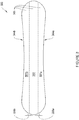
- Figure 3 depicts one embodiment of the snowboards described herein. Specifically, Figure 3 depicts the lower surface of a snowboard having two rails separated by a recess. As shown, the snowboard 300 has an upper surface (not shown), a lower surface 305, and one or more stiffened peripheral edges 304(a) and (b) , which are located on the left side and right side of the board, respectively.
- the peripheral edges 304a and 304b may form a single edge that surround the full periphery of the snowboard 300. Alternatively, in other embodiments, the edges 304a and 304b are separate edges on opposing longitudinal sides of the board.
- the lower surface 305 is continuous across the rails 301 and a recessed region 302 is arranged between the two rails 301a and 301b .
- the board is laminated from a series of layers. Typically the layers are wood, fiberglass and/or plastic, although other materials may be employed. These form the inner structure of the snowboard 300 and the inner layers (not shown) may be contoured in a shape that is similar to that of the lower surface 305 . In other embodiments, the inner layers (not shown) may be formed as a generally flat board and the rails 301 may be distinct components of the system that are attached separately to the lower surface 305. In either case, the contour of the lower surface 305 may be similar. When in use, the system makes contact with the snow across the width of contact 306 .
- the dimensions of the snowboard 305 may vary, and typically will be between 90 -170 cm in length as measured along a longitudinal axis extending along the length of the snow board 305 and between 20-30 cm in width as measured along a beam axis extending perpendicular to the longitudinal axis.
- the snowboard 305 has a generally hourglass shape, with curved lateral sides. Typically, both the front end and the back end are curved upward to lift the ends of the snowboard off the surface of eh snow when the lower surface 305 is placed on the snow surface. Other dimensions and shapes may be used without departing from the scope of the invention.
- Figure 4 depicts a cross-sectional detail of one embodiment of the snowboards described herein.
- system 300 has an upper surface 401 and a lower surface 305.
- the lower surface 305 is continuous across the left rail 301(a) , the recessed region 302 and the right rail 301(b) .
- Stiffened peripheral edge 304(a) and edge 304(b) are located at the left end and right ends, respectively.
- the downward force 406 is determined, in part, by weight of the person using the snowboard.
- the normal force 407 is distributed across the snow 404 on an area snow-to-board contact (not shown), which is determined, in part, by the width of snow-to-board contact 305. As the downward force 406 increases, the width of contact 305 may also increase.
- the width of contact 305 may also decrease.
- the snowboards described herein adjust to varying snow conditions.
- the board sinks lower in the snow thereby increasing the width of contact 306, which increases the normal force supporting the rider.
- the width of contact 306 may be large enough to include the entire width of the lower surface 305, including the surface area of rails 301 and the recessed region 302.
- the snowboard may rise toward the top of the surface and thereby decrease the area of contact 306.
- the width of contact 306 may be small and may only include the peak of rails 301(a) and (b) and not the surface of the recessed region 302. For conditions in between the soft and hard, the amount of board-to-snow contact varies as needed, such that the downward force 406 is equal to the normal force 407.
- the rails 301 run the length of the board.
- the length of contact is not altered relative to the conventional design but the width of contact is decreased.
- the claimed system is able to attain higher speeds on snow than a conventional system.
- the snowboard having the two rails on the bottom surface may be faster than a conventional snowboard.
- a pair of skis is faster than a standard snow board of the same length, and a catamaran is faster than a mono-hull boat of the same length.
- twin rails 301 are not rectangular in shape. Instead, they are angled upwards from the peak of the rail towards the periphery of the board. Thus, the rails have a tapered surface that progresses from the interior of the board to the peripheral edge.
- This design feature raises the edges 304 up above the snow when the operator is initiating a tum while operating the snowboard. The raised edges allow the user to travel on width of contact 306, without fear of unintentionally catching an edge. The result is increased comfort and, in part, safety and stability at high speeds. To initiate a carving tum, the rider must rotate the claimed system slightly further than the conventional system, ensuring that any edge-to-snow contact is intentional.
- Figure 5 depicts the snowboard of Figure 3 and 4 placed on a snow surface that is less firm and compact than the snow surface of Figure 4 .
- Figure 7 illustrates the snowboard 300 disposed over a snow surface 404.
- a force 406 typically the weight of the Rider, pushes the snowboard 300 against the snow surface 404.
- the rails 301(a) and 301(b) press more deeply into the snow surface 404 than under the conditions depicted by Figure 4 .
- the areas of contact 306(c) and 306(d) of the rails 301(a) and 301 (b) against the snow 404 are larger than the areas of contract 306(a) and 306(b) depicted in Figure 4 .
- the snow 404 may contact the recessed region 302 and press against the snowboard 302, at the rails 301(a) and 301(b) and at the recessed regions.
- Figure 6 depicts the lower surface 305 of the snowboard 300 and partially depicts binders and boots of a rider.
- the binders or bindings grip the rider's boot and hold the boot on the upper surface of the snowboard 300.
- the binding is arranged to position the heel of the boot 602 over one rail 301b and a toe of the boot (not shown) over a different rail 301a .
- the rider can lean forward or back to tip the snowboard 300 onto an edge 304 to carve a tum into the snow.
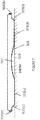
- Figure 7 depicts a cross-sectional detail of one embodiment of the claimed system designed to support and to enable motion for a person across a surface snow.
- the cross section of Figure 7 is one alternative to the cross section of Figure 4 .
- the lower surface 505 is continuous across the left rail 501(a) , the recessed region 502 , and the right rail 501(b).
- Edges 504(a) and 504(b) are located on the left side and right side of the board, respectively.
- Rails 501 extend along the full length of the long axis of the board and are raised relative recessed region 502. In an alternative embodiment rails 501 may only extend a portion of the length of the board.
- Recessed region 502 rises up to a lofted running surface, allowing the amount of surface area in contact with snow 510 to vary based on, for example, the type of snow (e.g., hard snow, soft snow), the weight of the user, the action performed by the user (e.g., slightly turning, sharply turning), the stance of the user (e.g., squatting stance, standing up straight, leaning).
- Inner edges 503(a) and 503(b) which form a first edge located on the lower surface of the board rise up from rails 501 up to a flat region of the lower surface of the board followed by outer edges 504(a) and 503(b).
- Outer edges 504(a) and 504(b) form a second edge located at a periphery of the upper surface.
- the first edge is thus at a different vertical location than the second edge, with the first edge being lower than the second edge as shown in Figure 7 .
- the first edge is also closer to the longitudinal axis than the second edge.
- the surface of the board located between the first or inner edge and the second or outer edge is concave, such this portion of the board surface is not in direct contact with the snow on the ground, and
- Inner edges 503(a) and 503(b) form soft edges and are made of the same material as the bottom surface of the board (e.g., p-tex).
- Outer edges 503(a) and 503(b) form hard edges and are made of a stiff material (e.g., metal, rigid plastic).
- the combination of the inner and outer edges allows the rider or user to control the amount of board-to-snow contact.
- the outer hard edges 504(a) and 504(b) engage the snow, a full carve or stop can be obtained.
- Having both the hard edges and the soft edges allow users to break contact between the snow and the hard edge which has a higher coefficient of friction, and to obtain contact between the snow and the soft edge, with a lower coefficient of friction.
- These inner or soft edges 503 allow users to ride without catching an edge and can be used to drift, 'butter,' turn and surf the snow.
- the outer hard edges 504(a) and 504(b) can once again engage the snow.
- the inner edges increase the ability to perform tricks, and flat spins without engaging the outer edges.
- the inner edges also benefit beginning snowboarders by allowing them to learn in a more intuitive and forgiving manner, resulting in less injuries.
- System 500 outperforms a conventional system in acceleration, maneuverability, and versatility based, in part, on the above features.
- Inner edges 503(a) and 503(b) sit below and inside of outer edges 503(a) and 503(b) .
- the "soft" inner edges 503(a) and 503(b) allow the rider to make small adjustments to direction without engaging the corresponding hard outer edge 503(a) or 503(b) with the snow.
- inner edges 503(a) and 503(b) allows the rider to drift their board without catching an edge (i.e. without unintentionally engaging hard outer edge 503(a) or 503(b) ) which feels smooth to the user, much like the carve of a surfboard.
- the rider When the rider chooses to turn sharply or come to a stop, they may engage the hard outer edge 503(a) or 503(b) .
- the board e.g., systems 300, 500
- the board rides up on the rails thereby reducing the surface area in contact with the snow and thus reducing drag, allowing the rider to accelerate faster, and attaining higher maximum speeds.
- soft snow e.g., powder-like snow
- the board sinks down slightly thereby increasing the surface area in contact with the snow and generating greater support for the user.
- the board enables a user to easily transition between different types of snow (e.g., hard snow, soft snow) by rising or sinking in the snow.
- the board performs well both as a race board (e.g., for high acceleration and speed) and in soft snow based, in part, on the variable surface area in contact with the snow.
- the board affords a user the ability to accelerate more quickly and reach high speeds faster than conventional systems, which yields improved performance (e.g., higher jumps, more time in the air after a jump to perform tricks).
- the design of the edges e.g., edges 304, 503, 504, or the combination thereof
- the increased acceleration rate allows a user to recover more quickly after an error than conventional systems.
- the shape of the board also allows the board to be stronger and thinner than conventional snowboards. Strength and durability of the board are improved, while the board is thinner and thus lighter than standard adult snowboards.
- the cross-section of the board includes four sigmoid, or s-shape surfaces: between outer edge 504(a) and inner edge 503(a), between surface 501(a) and recess (502), between recess (502) and surface 501(b), and between inner edge 503(b) and outer edge 504(b). These s-shaped surfaces provide sidewalls that extend orthogonally, or substantially orthogonally, to the upper surface of the board.
- This provides the board with a shape that increases the board's resistance to shear forces acting to crack or break the board along a line that is traverse to the sidewalls. Additionally, these s-curve surfaces may act as springs, storing potential energy when the board is flexed, and causing the board to produce significant 'pop' quickly.
- the shape of the board eliminates chatter at high speeds.
- Inner edges 503(a) and 503(b) are offset from the hard edges 504(a) and 504(b), respectively. Inner edges 503(a) and 503(b) may be between 8 and 11mm closer to the board's longitudinal axis than outer edges 504(a) and 504(b).
- the thickness of the board varies both transversely, as shown in the cross-section of Figure 7 , and longitudinally. In the longitudinal direction the board is thickest where the rider's feet are located, and gradually thinner both to the left and to the right of the rider's feet, i.e. closer to the ends of the board. Accordingly, as shown in Figure 7 the thickness varies between 1.5 mm and 6.5 mm at the longitudinal axis, and the thickness of the rails 501(a) and 501(b) varies between 3 and 8 mm.
- Empirical research has shown that a board with the features described above can accelerate up to 25% faster than a standard board. Empirical research has also shown that this board is 1.5 to 2 times stronger than a standard board, and the risk of breakage is significantly reduced.
- the layers of the disclosed snowboard may be constructed, in part, using a mold, which is designed having a shape consistent with the contours of the claimed system.
- Other example manufacturing methods may have an expandable bladder, placed in an enclosure with the layers of the system and the mold. As the bladder expands, it applies pressure to the layers, forcing them against the mold and imparting the contours of the mold.
- struts made of wood, are used to help distribute the pressure from the bladder to the layers of the system.
- the layers of the system may be pressed together using a pneumatic press, which applies pressure to the layers, forcing them against the opposing surface of the press and imparting the contours of the claimed system.
Description
- The systems and methods described herein relate to sporting equipment. Specifically, snowboards and other systems and methods for enabling motion of a person across a surface of snow.
- Sportsmen and engineers have designed different types of snowboards to travel over the surface of the snow. Snowboards travel differently than skis and sleds. In particular, snowboards allow users to lift up on or tilt onto an edge of the board and use the force of the board's edge against the snow surface to tum direction. This type of turning is called carving and it essentially allows the skilled snowboarder to make tight radius turns. Unlike with skis, the snowboarder positions his or her feet transverse to the longitudinal axis of the board. This means that the snowboarder must lean forward or backwards to tilt the board on to one of its edges. This takes quite a bit of skill to achieve, but the benefit is that the snowboard turns using a process that keeps the velocity of the board, both speed and direction, aligned with the turned patch of the snowboard. In contrast, turning without rising on to an edge, maintains the full wide bottom surface of the snow board against the snow road forces the rider to essentially drag the bottom surface of the board until the snow board points in the proper direction. This manner of turning is called skidding. Skidding the board slows the rider because the frictional force of the board against the snow is not aligned with the direction of travel and therefore results in a strong frictional stopping force. Frictional forces between the board and snow surface can make riding more difficult and less fun.
- Engineers and sportsmen have endeavored to reduce the frictional forces that slow and make less stable the movement of a snowboard across the snow. The interaction between the board and the snow impacts the performance of the board and rider. For example,
US Patent 8,356,822 describes engagement devices that can attach to the bottom of a snowboard to change how it engages with the snow and performs.US Patent 6,193,244 discusses a snowboard having two edges on the bottom surface for contacting the snow to reduce skidding. Still there remains a need for improved systems and devices for improving and altering the performance of snow boards. -
US 5,340,144 discloses a vehicle for travel on snow or water consisting of an elongated main member having a top and a bottom surface with a venturi effect. First and second runners extend lengthwise and downwardly along opposed edges of the bottom surface from a point spaced rearwardly of the front end of the member to a point spaced forwardly of the rear end of the member. The runners and bottom surface define the venturi section that tapers inwardly to a narrow throat in the vicinity of the middle of the member and then tapers outwardly. Elongated side cuts are provided to the elongated outside surfaces of the board, the side cuts creating a surface which is narrower in width between the front and the back of the surface. -
US 2009/0102161 discloses a snowboard or ski or the like comprising a base body having at least one edge, a top surface and a bottom surface; wherein the edge comprises at least one channel formed therein to provide two or more edge elements to contact a medium during use. - Described herein are a system and method for supporting a person and enabling motion of a person across a surface of snow while satisfying the countervailing requirements of increasing surface area for weight-carrying capacity on soft snow and reducing the opposing forces, like for example drag and friction, in hard snow. More specifically, according to the invention there is provided a snowboard according to claim 1 and a method of manufacturing a snowboard according to claim 12.
- In general, the system is designed to support the weight of the user and to provide motion across the surface of snow. The weight-carrying capacity of snow increases with compaction. Soft, uncompact snow has a lower weight-carrying capacity than hard, compact snow. When the weight-carrying capacity of snow is exceeded, the snow compacts until it reaches the requisite weight-carrying capacity to support the applied weight. The area of contact between the system and the snow is calculated by multiplying the width of contact between the system and the snow by the length of contact between the system and the snow. The system carries the weight of the user by transferring the weight to the snow surface across the area of contact. The maximum operating speed of the system is, in part, determined by magnitude of opposing forces that occur at the area of contact between the system and the snow surface. The opposing forces may be generated by friction, drag or other forces that oppose the primary direction of travel while the system is in use. Opposing forces have a negative impact on the maximum speed of the system.
- Conventional systems are designed for use in one of either soft snow or hard snow. In soft snow, it is desirable for the weight of the user to be supported on a large area of contact between the system and the snow, without little or no compaction required. The large area of contact places more snow under the system to support the weight of a user; it allows the user to "glide" across the surface of snow without sinking into the snow, which would increase the magnitude of opposing forces. In hard snow, it is desirable for the weight of the user to be supported on a small area of contact between the system and the snow. The small area of contact between the system and the snow reduces the magnitude of opposing forces, such as an opposing frictional force, which, in part, contributes to an increased maximum speed of the system. In the design of a conventional system, the width of contact between the system and the snow is fixed. Therefore, it is not possible to substantially increase or decrease the width of contact in response to varying snow conditions.
- Consequently, many expert users carry more than one system; one wide system for soft snow conditions and one other narrow system for hard snow conditions. The soft snow system is significantly wider than the hard snow system. The increased width of the soft snow system increases the horizontal surface area, and increases the normal force supporting the user. A conventional system that is designed for soft-snow causes unnecessary drag and friction when operated on hard snow. In addition, when operating a conventional system, the user must be careful not to operate the system in a substantially flat position. A flat position is characterized by two opposing edges of the system touching the snow simultaneously. Often, the two edges are oriented perpendicular to the primary direction of travel. When the standard system is operated in a flat position, it has the potential to pitch and/or yaw, causing an edge of the system to unintentionally catch and stop in the snow, which generally results in the rider falling down. This phenomenon is sometimes called "catching an edge" and is potentially dangerous for the rider.
- The snowboards described here address the countervailing requirements of increasing area for weight-carrying capacity on soft snow and reducing the opposing forces in hard snow. Moreover, these snowboards reduce the likelihood of unintentionally catching an edge in the snow. The system and methods disclosed herein support the weight of the user and enable motion at a high maximum speed on snow while satisfying the countervailing requirements of increasing weight-carrying capacity reducing opposing forces. Among other features, the systems includes a contoured lower surface that sinks lower in soft snow and rises higher in hard snow. The lower surface has at least two rails and a recessed region, which provide additional surface area for transferring weight to the snow. The amount of area contacting the snow adjusts based on, in part, the rider's speed, weight and the current snow conditions. The rails on the lower surface are sloped up toward the periphery of the system, which lifts the edges up from the snow surface and thereby reduces the likelihood of unintentionally catching an edge in the snow. More specifically, the systems and methods described herein include, among other things, snowboards having a board with an upper surface and a lower surface and a first and second end. Typically, both the first and second ends are curved upward, to lift the ends of the board off the surface of the snow, as commonly done with snowboards. The upper surface has locations for a first binding and a second binding to allow the bindings to be arranged transverse to a longitudinal axis extending through the first and second ends. The lower surface has a first and a second rail extending along the longitudinal axis and being separated by a recess extending along the longitudinal axis. The rails and the recess all have a width, as measured transverse to the longitudinal axis of the board. The width of the recess is typically, but not necessarily, greater than the width of each respective rail and the first and second rails and the recess extend across the width of the bottom surface and substantially the length of the bottom surface of the board.
- Optionally, the snowboard may have first and second rails that have respective interior shoulder walls having an at least 30° inclination from an axis parallel to a beam of the board. Further optionally, the snowboard may have first and second rails have a width substantially equal to one quarter the width of the bottom surface of the board. Typically, but optionally, the snowboard may have one or more bindings for gripping a boot of a rider, and the binding may be arranged to position a heel of the boot over one rail and a toe of the boot over a different rail. The snowboard may have first and second rails that have surfaces for contacting the snow, the surfaces being tapered to narrow in thickness from the recess to the peripheral edge of the board.
- Optionally, when the board rests against a flat surface, the peripheral edge of the board is raised above the flat surface. The peripheral edge may be raised between about 1 mm and 8 mm above the flat surface, or any other suitable distance. In manufacture, the snowboard may have first and second rails that comprise modular bodies for being secured to the bottom surface of the board. Alternatively, the snowboard may have first and second rails that comprise rails integrally formed as part of the bottom surface of the board. Further optionally, the snowboard, under typical operating conditions, has rails with a width selected to support the weight of a user, and thereby have the recessed surface apply a force less than the weight of the user, which may include no substantial force, to the surface of the snow, such that the center of the board applies little or no force to the surface of the snow and frictional forces generated against the center of the board are reduced or eliminated.
- The foregoing and other objects and advantages of the invention will be appreciated more fully from the following further description thereof, with reference to the accompanying drawings wherein;
-
Figure 1 depicts prior art snowboard designed to support and to enable motion for a person on snow; -
Figure 2 depicts a cross-sectional view of a prior art snowboard; -
Figure 3 depicts one embodiment of a snowboard designed to support and to enable motion for a person on snow; -
Figure 4 depicts a cross-sectional view of one embodiment of a snowboard as described herein; -
Figure 5 depicts a cross-sectional view of a snowboard such as the snowboard inFigure 4 , and placed on a snow surface of less compact snow; -
Figure 6 depicts the lower surface of the snowboard ofFigure 3 having two rails, and partially shows a rider with bindings attached to the upper surface of the snowboard; and -
Figure 7 depicts a cross-sectional view of a one embodiment of a snowboard as described herein. - Certain illustrative embodiments will now be described, including a snowboard that supports the weight of the user and enables the user to move across the surface of snow at a high speed while satisfying the countervailing requirements of increasing weight-carrying capacity and reducing opposing forces, such as opposing frictional forces. However, it will be understood by one of ordinary skill in the art that the systems and methods described herein can be adapted and modified for other suitable applications and that such other additions and modifications will not depart from the scope hereof.
- In certain embodiments, the snowboard has a bottom surface having two rails. The two rails run the length, or substantially the length, of the snow board and these two rails are separated by a recess, so that the two rails are arranged to place one along each side of the snowboard. The rails have a bottom surface that contacts the snow. Under certain operating conditions, such as when the snow is compact and firm enough to prevent or reduce the rails from sinking more than a few millimeters into the snow, the snowboard moves over the snow with the rails in contact with the snow surface and the recessed portion of the board spaced away from the compact snow surface.
- Optionally, the rails may have a tapered surface. The taper may progress from the interior side of the rail adjacent to the recess toward the peripheral edge of the board. The taper spaces the peripheral edge of the board away from a flat surface on which the rails may rest. The tapered surfaces are examples of a contoured lower surface having dual rails.
- Among other features, the contoured lower surface may sink lower in soft snow and ride higher in hard snow. The amount of area contacting the snow adjusts based on, in part, the rider's speed, weight and the snow conditions. The rails on the lower surface may optionally be sloped up toward the periphery of the board and may reduce the likelihood of unintentionally catching an edge in the snow, and thereby improve stability.
-
Figure 1 depicts aprior art snowboard 100 designed to support the weight of a person and to enable motion on snow. Thesnowboard 100 contains at least one rigid element, wherein each rigid element has an upper surface (not shown), alower surface 203 and one or more stiffened peripheral edges 101(a) and (b). Edges 101(a) and (b) are located on left and right ends and, in some embodiments, may line the entire periphery of the system. Edges 101 may be made of metal, alloy or any other suitable material. -
Figure 2 depicts a cross-sectional detail of the prior art snowboard ofFigure 1 . Thesnowboard 100 has anupper surface 201, alower surface 203, and a plurality of inner-layers 202 positioned between theupper surface 201 andlower surface 203. Edges 101 (a) and (b) are located on left and right ends, respectively. Thelower surface 203 rests on thesnow surface 204. Thedownward force 206 is transferred through thesystem 100 and is balanced by thenormal force 207. -
Upper surface 201 may be made of a glossy material, which serves as a medium to place graphic designs and also a UV protectant layer.Lower surface 203 is typically a polyethylene and serves to reduce friction between the bottom of the system and the surface of travel. Inner-layers 202 are made of hardwood placed in between layers of fiberglass. - During operation, the
snowboard 100 reaches a physical equilibrium state wherein thenormal force 207 is equal todownward force 206. Thedownward force 206 is determined, in part, by weight of the person on thesnowboard 100. Thenormal force 207 is distributed across thesnow 204 on an area snow-to-board contact (not shown), which is determined, in part, by the width of snow-to-board contact 205. For the prior art snowboard, the width ofcontact 205 remains constant even as thedownward force 206 increases. -
Figure 3 depicts one embodiment of the snowboards described herein. Specifically,Figure 3 depicts the lower surface of a snowboard having two rails separated by a recess. As shown, thesnowboard 300 has an upper surface (not shown), alower surface 305, and one or more stiffened peripheral edges 304(a) and (b), which are located on the left side and right side of the board, respectively. Theperipheral edges snowboard 300. Alternatively, in other embodiments, theedges lower surface 305 is continuous across the rails 301 and a recessedregion 302 is arranged between the tworails snowboard 300 and the inner layers (not shown) may be contoured in a shape that is similar to that of thelower surface 305. In other embodiments, the inner layers (not shown) may be formed as a generally flat board and the rails 301 may be distinct components of the system that are attached separately to thelower surface 305. In either case, the contour of thelower surface 305 may be similar. When in use, the system makes contact with the snow across the width of contact 306. - The dimensions of the
snowboard 305 may vary, and typically will be between 90 -170 cm in length as measured along a longitudinal axis extending along the length of thesnow board 305 and between 20-30 cm in width as measured along a beam axis extending perpendicular to the longitudinal axis. Thesnowboard 305 has a generally hourglass shape, with curved lateral sides. Typically, both the front end and the back end are curved upward to lift the ends of the snowboard off the surface of eh snow when thelower surface 305 is placed on the snow surface. Other dimensions and shapes may be used without departing from the scope of the invention.Figure 4 depicts a cross-sectional detail of one embodiment of the snowboards described herein. According to one embodiment,system 300 has anupper surface 401 and alower surface 305. Thelower surface 305 is continuous across the left rail 301(a), the recessedregion 302 and the right rail 301(b). Stiffened peripheral edge 304(a) and edge 304(b) are located at the left end and right ends, respectively. Thedownward force 406 is determined, in part, by weight of the person using the snowboard. Thenormal force 407 is distributed across thesnow 404 on an area snow-to-board contact (not shown), which is determined, in part, by the width of snow-to-board contact 305. As thedownward force 406 increases, the width ofcontact 305 may also increase. - Likewise, as the
downward force 406 decreases, the width ofcontact 305 may also decrease. In operation, the snowboards described herein adjust to varying snow conditions. In soft snow, the board sinks lower in the snow thereby increasing the width of contact 306, which increases the normal force supporting the rider. In some soft snow conditions, the width of contact 306 may be large enough to include the entire width of thelower surface 305, including the surface area of rails 301 and the recessedregion 302. In hard snow, the snowboard may rise toward the top of the surface and thereby decrease the area of contact 306. In some hard snow conditions, the width of contact 306 may be small and may only include the peak of rails 301(a) and (b) and not the surface of the recessedregion 302. For conditions in between the soft and hard, the amount of board-to-snow contact varies as needed, such that thedownward force 406 is equal to thenormal force 407. - Turning to
Figures 3 and4 , the rails 301 run the length of the board. Thus, the length of contact is not altered relative to the conventional design but the width of contact is decreased. By keeping the length of contact between the system and the snow constant, and by decreasing the width of contact between the system and the snow, the claimed system is able to attain higher speeds on snow than a conventional system. Not to be bound by theory, but the snowboard having the two rails on the bottom surface, may be faster than a conventional snowboard. For the same physical principles that a pair of skis is faster than a standard snow board of the same length, and a catamaran is faster than a mono-hull boat of the same length. - Also depicted in
Figure 4 , the twin rails 301, are not rectangular in shape. Instead, they are angled upwards from the peak of the rail towards the periphery of the board. Thus, the rails have a tapered surface that progresses from the interior of the board to the peripheral edge. This design feature raises the edges 304 up above the snow when the operator is initiating a tum while operating the snowboard. The raised edges allow the user to travel on width of contact 306, without fear of unintentionally catching an edge. The result is increased comfort and, in part, safety and stability at high speeds. To initiate a carving tum, the rider must rotate the claimed system slightly further than the conventional system, ensuring that any edge-to-snow contact is intentional. -
Figure 5 depicts the snowboard ofFigure 3 and4 placed on a snow surface that is less firm and compact than the snow surface ofFigure 4 . Specifically,Figure 7 illustrates thesnowboard 300 disposed over asnow surface 404. Aforce 406, typically the weight of the Rider, pushes thesnowboard 300 against thesnow surface 404. In the conditions represented byFigure 5 , the rails 301(a) and 301(b) press more deeply into thesnow surface 404 than under the conditions depicted byFigure 4 . The areas of contact 306(c) and 306(d) of the rails 301(a) and 301 (b) against thesnow 404 are larger than the areas of contract 306(a) and 306(b) depicted inFigure 4 . In still less firm conditions, thesnow 404 may contact the recessedregion 302 and press against thesnowboard 302, at the rails 301(a) and 301(b) and at the recessed regions. -
Figure 6 depicts thelower surface 305 of thesnowboard 300 and partially depicts binders and boots of a rider. As shown, the binders or bindings grip the rider's boot and hold the boot on the upper surface of thesnowboard 300. The binding is arranged to position the heel of the boot 602 over onerail 301b and a toe of the boot (not shown) over adifferent rail 301a. To tum, the rider can lean forward or back to tip thesnowboard 300 onto an edge 304 to carve a tum into the snow. -
Figure 7 depicts a cross-sectional detail of one embodiment of the claimed system designed to support and to enable motion for a person across a surface snow. The cross section ofFigure 7 is one alternative to the cross section ofFigure 4 . Thelower surface 505 is continuous across the left rail 501(a), the recessedregion 502, and the right rail 501(b). Edges 504(a) and 504(b) are located on the left side and right side of the board, respectively.Rails 501 extend along the full length of the long axis of the board and are raised relative recessedregion 502. In an alternative embodiment rails 501 may only extend a portion of the length of the board. Recessedregion 502 rises up to a lofted running surface, allowing the amount of surface area in contact withsnow 510 to vary based on, for example, the type of snow (e.g., hard snow, soft snow), the weight of the user, the action performed by the user (e.g., slightly turning, sharply turning), the stance of the user (e.g., squatting stance, standing up straight, leaning). Inner edges 503(a) and 503(b), which form a first edge located on the lower surface of the board rise up fromrails 501 up to a flat region of the lower surface of the board followed by outer edges 504(a) and 503(b). Outer edges 504(a) and 504(b) form a second edge located at a periphery of the upper surface. The first edge is thus at a different vertical location than the second edge, with the first edge being lower than the second edge as shown inFigure 7 . The first edge is also closer to the longitudinal axis than the second edge. The surface of the board located between the first or inner edge and the second or outer edge is concave, such this portion of the board surface is not in direct contact with the snow on the ground, and Inner edges 503(a) and 503(b) form soft edges and are made of the same material as the bottom surface of the board (e.g., p-tex). Outer edges 503(a) and 503(b) form hard edges and are made of a stiff material (e.g., metal, rigid plastic). - The combination of the inner and outer edges allows the rider or user to control the amount of board-to-snow contact. When the outer hard edges 504(a) and 504(b) engage the snow, a full carve or stop can be obtained. Having both the hard edges and the soft edges allow users to break contact between the snow and the hard edge which has a higher coefficient of friction, and to obtain contact between the snow and the soft edge, with a lower coefficient of friction. These inner or
soft edges 503 allow users to ride without catching an edge and can be used to drift, 'butter,' turn and surf the snow. When a user leans the board beyond the soft edge, the outer hard edges 504(a) and 504(b) can once again engage the snow. For experienced users, the inner edges increase the ability to perform tricks, and flat spins without engaging the outer edges. The inner edges also benefit beginning snowboarders by allowing them to learn in a more intuitive and forgiving manner, resulting in less injuries. - System 500 outperforms a conventional system in acceleration, maneuverability, and versatility based, in part, on the above features. Inner edges 503(a) and 503(b) sit below and inside of outer edges 503(a) and 503(b). The "soft" inner edges 503(a) and 503(b) allow the rider to make small adjustments to direction without engaging the corresponding hard outer edge 503(a) or 503(b) with the snow. In addition, inner edges 503(a) and 503(b) allows the rider to drift their board without catching an edge (i.e. without unintentionally engaging hard outer edge 503(a) or 503(b)) which feels smooth to the user, much like the carve of a surfboard. When the rider chooses to turn sharply or come to a stop, they may engage the hard outer edge 503(a) or 503(b). When traveling on hard snow (e.g., hard-packed snow) the board (e.g.,
systems 300, 500) rides up on the rails thereby reducing the surface area in contact with the snow and thus reducing drag, allowing the rider to accelerate faster, and attaining higher maximum speeds. When traveling on soft snow (e.g., powder-like snow), the board sinks down slightly thereby increasing the surface area in contact with the snow and generating greater support for the user. Thus, the board enables a user to easily transition between different types of snow (e.g., hard snow, soft snow) by rising or sinking in the snow. The board performs well both as a race board (e.g., for high acceleration and speed) and in soft snow based, in part, on the variable surface area in contact with the snow. When used in a snowboard half-pipe, the board affords a user the ability to accelerate more quickly and reach high speeds faster than conventional systems, which yields improved performance (e.g., higher jumps, more time in the air after a jump to perform tricks). The design of the edges (e.g., edges 304, 503, 504, or the combination thereof) provides a more forgiving surface when landing tricks, similar to the reverse camber design, but it does not sacrifice "pop" like reverse camber does. Moreover, the increased acceleration rate allows a user to recover more quickly after an error than conventional systems. - The shape of the board also allows the board to be stronger and thinner than conventional snowboards. Strength and durability of the board are improved, while the board is thinner and thus lighter than standard adult snowboards. The cross-section of the board includes four sigmoid, or s-shape surfaces: between outer edge 504(a) and inner edge 503(a), between surface 501(a) and recess (502), between recess (502) and surface 501(b), and between inner edge 503(b) and outer edge 504(b). These s-shaped surfaces provide sidewalls that extend orthogonally, or substantially orthogonally, to the upper surface of the board. This provides the board with a shape that increases the board's resistance to shear forces acting to crack or break the board along a line that is traverse to the sidewalls. Additionally, these s-curve surfaces may act as springs, storing potential energy when the board is flexed, and causing the board to produce significant 'pop' quickly. Advantageously, the shape of the board eliminates chatter at high speeds.
- The inner edges 503(a) and 503(b) are offset from the hard edges 504(a) and 504(b), respectively. Inner edges 503(a) and 503(b) may be between 8 and 11mm closer to the board's longitudinal axis than outer edges 504(a) and 504(b).
- The thickness of the board varies both transversely, as shown in the cross-section of
Figure 7 , and longitudinally. In the longitudinal direction the board is thickest where the rider's feet are located, and gradually thinner both to the left and to the right of the rider's feet, i.e. closer to the ends of the board. Accordingly, as shown inFigure 7 the thickness varies between 1.5 mm and 6.5 mm at the longitudinal axis, and the thickness of the rails 501(a) and 501(b) varies between 3 and 8 mm. - Empirical research has shown that a board with the features described above can accelerate up to 25% faster than a standard board. Empirical research has also shown that this board is 1.5 to 2 times stronger than a standard board, and the risk of breakage is significantly reduced.
- The manufacture of the disclosed snow board may be accomplished employing methods that are familiar to those skilled in the art. For example, the layers of the disclosed snowboard may be constructed, in part, using a mold, which is designed having a shape consistent with the contours of the claimed system. Other example manufacturing methods may have an expandable bladder, placed in an enclosure with the layers of the system and the mold. As the bladder expands, it applies pressure to the layers, forcing them against the mold and imparting the contours of the mold. In some embodiments of a manufacturing system struts, made of wood, are used to help distribute the pressure from the bladder to the layers of the system. In other embodiments of a manufacturing method, the layers of the system may be pressed together using a pneumatic press, which applies pressure to the layers, forcing them against the opposing surface of the press and imparting the contours of the claimed system.
- Accordingly, it will be understood that the invention is not to be limited to the embodiments disclosed herein, but is to be understood from the following claims, which are to be interpreted as broadly as allowed under the law.
Claims (12)
- A snowboard (300), comprising:a board having an upper surface (401), a lower surface (305, 505), a first and a second end, a first peripheral edge (304a, 504a) and a second peripheral edge (304b, 504b), wherein a longitudinal axis of the board extends through the first and second ends,the lower surface having a first rail (301a, 501a) and a second rail (301b, 501b) extending along the longitudinal axis, and the rails being separated by a recess (302, 502) extending along the longitudinal axis, the rails and the recess each having a width measured transverse to the longitudinal axis and the width of the recess being greater than the width of each respective rail, and the first and second rails and the recess extending along the length of the lower surface, andthe first peripheral edge being located at a periphery of the board, and the first rail being located on the lower surface and closer than the first peripheral edge to the longitudinal axis, andthe second peripheral edge being located at a periphery of the board, and the second rail being located on the lower surface and closer than the second peripheral edge to the longitudinal axis,characterised in that:
a thickness of the respective rail decreases in a direction from the recess toward the first peripheral edge of the board and the second peripheral edge of the board, respectively. - The snowboard according to Claim 1, wherein a surface of the board between the first rail and the first peripheral edge is concave.
- The snowboard according to Claim 1, wherein the first rail is made with a first material, and the first peripheral edge is made with a second material, and wherein the second material is stiffer than the first material.
- The snowboard according to Claim 1, wherein when the board rests on a flat surface a contact portion (306c) of the first rail is in contact with the flat surface, and the first peripheral edge is raised above the flat surface.
- The snowboard according to Claim 4, wherein the first peripheral edge is raised between about 1 mm and 8 mm above the flat surface.
- The snowboard according to Claim 1, where the first and second rails have respective interior shoulder walls having an at least 30° inclination from an axis parallel to a beam of the board.
- The snowboard according to Claim 1, wherein the first and second rails have a width equal to one quarter the width of the lower surface.
- The snowboard according to Claim 1, further comprising a binding for gripping a boot of a rider, and wherein the binding is arranged to position a heel of the boot over one rail and a toe of the boot over a different rail.
- The snowboard according to Claim 1, wherein the first and second rails comprise modular bodies for being secured to the lower surface of the board.
- The snowboard according to Claim 1, wherein the first and second rails comprise rails integrally formed as part of the lower surface of the board.
- The snowboard according to Claim 1, wherein, under typical operating conditions, the width of the rails is selected to support a weight of a user, and thereby have a surface of the recess apply a force less than the weight of the user to a snow surface.
- A method of manufacturing a snowboard, comprising
providing a board (300) having an upper surface (401) and a lower surface (305, 505), a first end and a second end, a first peripheral edge (304a, 504a) and a second peripheral edge (304b, 504b), wherein a longitudinal axis of the board extends through the first and second ends, and
forming on the lower surface a first and a second rail (301a, 301b; 501a, 501b) extending along the longitudinal axis and being separated by a recess (302, 502) extending along the longitudinal axis, wherein the rails and the recess each have a width measured transverse to the longitudinal axis and the width of the recess being greater than the width of each respective rail and the first and second rails and the recess extending along the length of the lower surface,
wherein the first peripheral edge is located at a periphery of the board, and the first rail is located on the lower surface and closer than the first peripheral edge to the longitudinal axis, and the second peripheral edge being located at a periphery of the board, and the second rail being located on the lower surface and closer than the second peripheral edge to the longitudinal axis, and
wherein a thickness of the respective rail decreases in a direction from the recess toward the first peripheral edge of the board and the second peripheral edge of the board, respectively.
Applications Claiming Priority (2)
| Application Number | Priority Date | Filing Date | Title |
|---|---|---|---|
| US201361959275P | 2013-08-19 | 2013-08-19 | |
| PCT/US2014/051611 WO2015026772A1 (en) | 2013-08-19 | 2014-08-19 | Snowboard with modified rails and edges |
Publications (3)
| Publication Number | Publication Date |
|---|---|
| EP3036019A1 EP3036019A1 (en) | 2016-06-29 |
| EP3036019A4 EP3036019A4 (en) | 2016-11-02 |
| EP3036019B1 true EP3036019B1 (en) | 2020-07-29 |
Family
ID=52466296
Family Applications (1)
| Application Number | Title | Priority Date | Filing Date |
|---|---|---|---|
| EP14838724.4A Active EP3036019B1 (en) | 2013-08-19 | 2014-08-19 | Snowboard with modified rails and edges |
Country Status (3)
| Country | Link |
|---|---|
| US (3) | US9120003B2 (en) |
| EP (1) | EP3036019B1 (en) |
| WO (1) | WO2015026772A1 (en) |
Families Citing this family (1)
| Publication number | Priority date | Publication date | Assignee | Title |
|---|---|---|---|---|
| US9950242B2 (en) * | 2015-06-19 | 2018-04-24 | Anton F. Wilson | Automatically adaptive ski |
Family Cites Families (61)
| Publication number | Priority date | Publication date | Assignee | Title |
|---|---|---|---|---|
| US1998702A (en) | 1934-04-13 | 1935-04-23 | Boline John | Ski |
| US2259327A (en) * | 1938-05-04 | 1941-10-14 | Eric Pusinelli | Ski runner |
| US2950701A (en) | 1956-09-18 | 1960-08-30 | Az Fabbrica Motocicli E Veloci | Boat with two spaced hulls |
| US3027575A (en) | 1957-06-26 | 1962-04-03 | Fortin Plastics Inc | Water ski |
| US3077617A (en) | 1961-01-26 | 1963-02-19 | Lu Verne G Steffel | Water ski construction |
| US3099025A (en) | 1963-03-29 | 1963-07-30 | Thurman G Merkley | Water ski |
| GB1033352A (en) | 1964-01-24 | 1966-06-22 | Carlton Tyre Saving Co Ltd | An improved pair of skis |
| US3381972A (en) | 1965-02-09 | 1968-05-07 | Miller Earl Andrew | Ski provided with tracking means |
| US3503621A (en) | 1968-05-08 | 1970-03-31 | Kimball Schmidt Inc | Fiber glass ski with channel construction |
| CH569493A5 (en) | 1972-06-08 | 1975-11-28 | Bildner Heinz | |
| USRE29659E (en) | 1972-06-08 | 1978-06-06 | Radial ski having a profiled running surface | |
| US3782744A (en) * | 1972-09-29 | 1974-01-01 | D Milovich | Snow surfboard with stepped stabilizing sides |
| AT346742B (en) | 1976-02-13 | 1978-11-27 | Kaestle Gmbh | SKI |
| GB1505092A (en) | 1976-05-21 | 1978-03-22 | Ford H | Skis |
| DE2936368A1 (en) * | 1979-09-08 | 1981-04-02 | Müller + Müller, Basel | SNOW SLIDER |
| US4340241A (en) | 1980-04-14 | 1982-07-20 | Crocket Danial E | Ski |
| US4433855A (en) | 1980-06-06 | 1984-02-28 | Wyke Paul R | Snow ski |
| US4524984A (en) | 1980-08-19 | 1985-06-25 | Axelson Peter W | Controllable sled for snow skiing |
| US4608023A (en) | 1983-07-27 | 1986-08-26 | Ski-Ace Pty. Limited | Water ski |
| US4603870A (en) | 1984-05-30 | 1986-08-05 | Monreal F Javier | Kneeling or sitting sled |
| DE3441058A1 (en) * | 1984-11-09 | 1986-05-15 | Kneissl International GmbH, 8028 Taufkirchen | Ski, especially jumping ski |
| US5301965A (en) * | 1985-01-07 | 1994-04-12 | Richard Floreani | Snow ski |
| FR2598932B1 (en) | 1986-05-23 | 1988-09-02 | Salomon Sa | DISSYMMETRIC PROFILE SKIING |
| FR2625906B1 (en) * | 1988-01-18 | 1990-06-29 | Remondet Jean Pierre | SNOW SURFING |
| US5052963A (en) | 1990-02-01 | 1991-10-01 | Wellington Leisure Products, Inc. | Textured water ski |
| US5340144A (en) | 1992-10-08 | 1994-08-23 | Eleneke Charles L | Dynamic fluid engaging surface for vehicles |
| US5303949A (en) * | 1993-04-26 | 1994-04-19 | Harper Luke J | Multi-edged downhill snow skis |
| DE9306333U1 (en) | 1993-04-27 | 1993-09-02 | Hess Eugen | ski |
| US5462304A (en) * | 1993-10-25 | 1995-10-31 | Nyman; Bengt E. | Snowboard with dual-acting, interchangeable edges |
| US5580078A (en) | 1993-11-12 | 1996-12-03 | Vance; Mark D. | Double-edged snowboard |
| US6382658B1 (en) | 1997-11-19 | 2002-05-07 | North Shore Partners | Method of making a snowboard having improved turning performance |
| US6394483B2 (en) | 1997-11-19 | 2002-05-28 | North Shore Partners | Snowboard body |
| US6276699B1 (en) | 1998-02-25 | 2001-08-21 | Verlin M. Simmons | Snow machine ski |
| US6193244B1 (en) | 1998-10-26 | 2001-02-27 | Mark D. Vance | Dual edge snowboard with straight edge portions |
| US6224085B1 (en) * | 1999-01-11 | 2001-05-01 | Mark Cruz | Tunnelboard snowboard |
| US6866273B2 (en) * | 2000-12-08 | 2005-03-15 | The Burton Corporation | Sliding device |
| US20020105166A1 (en) | 2001-02-02 | 2002-08-08 | Rene Lemieux | Snowmobile ski |
| USD471842S1 (en) | 2001-02-15 | 2003-03-18 | Bombardier Inc. | Snowmobile ski |
| US6533625B1 (en) | 2001-12-03 | 2003-03-18 | Paul E. Taylor | Water ski |
| CA2385832A1 (en) | 2002-05-10 | 2003-11-10 | Curtis G. Walker | Snow skates |
| US6955236B2 (en) | 2002-06-21 | 2005-10-18 | Starting Line Products, Inc. | Snowmobile ski |
| FR2847483B1 (en) | 2002-11-22 | 2004-12-24 | Rossignol Sa | SLIDING BOARD AND METHOD FOR MANUFACTURING SUCH A SLIDING BOARD |
| US6974139B2 (en) | 2003-02-18 | 2005-12-13 | Arctic Cat Inc. | Dual ski skag |
| US7073810B2 (en) | 2003-06-25 | 2006-07-11 | Wilson Anton F | Ski with tunnel and enhanced edges |
| DE20316335U1 (en) * | 2003-10-22 | 2004-03-11 | Boards & More Ag, Clarens | snowboard |
| DE10359228A1 (en) | 2003-12-17 | 2005-07-14 | Kneissl Tirol Gmbh | Snow glider, especially carving skis |
| US7219916B2 (en) | 2004-10-07 | 2007-05-22 | Olson Mark A | Snowboard |
| US20060082089A1 (en) | 2004-10-18 | 2006-04-20 | Demetrias Rejtano | Versatile sports board |
| US7445227B2 (en) * | 2005-03-16 | 2008-11-04 | Harris Jr Gerald W | Ski with improved edging characteristics |
| US8579301B2 (en) * | 2005-12-09 | 2013-11-12 | Shane Smith | Articulated two-piece snowboard with rigid, flexible connector |
| FR2898063A1 (en) | 2006-03-02 | 2007-09-07 | Salomon Sa | INTERFACE DEVICE FOR A SLIDING BOARD |
| AT504801B1 (en) | 2007-02-02 | 2009-05-15 | Atomic Austria Gmbh | SCHI OR SNOWBOARD WITH A MEANS FOR INFLUENCING ITS GEOMETRY AND METHOD FOR THE PRODUCTION THEREOF |
| AT504840B1 (en) | 2007-02-02 | 2009-07-15 | Atomic Austria Gmbh | SCHI OR SNOWBOARD IN THE SHAPE OF A BRETTY SLIDER |
| US20080293506A1 (en) | 2007-05-23 | 2008-11-27 | Northam Christopher Dale | Hydroplane sporting environment and devices and methods therefor |
| US8075014B2 (en) | 2007-10-04 | 2011-12-13 | Peter F. Phibbs | Snowboard or ski or the like having a channeled edge or multiple element edge |
| US8246070B2 (en) * | 2007-12-14 | 2012-08-21 | An Hao Adams Lin | Snow glider with elevated chatter-absorbing rider deck |
| US20100171288A1 (en) | 2009-01-07 | 2010-07-08 | Steep N Deep, LLC | Adjustable width ski |
| US20110204596A1 (en) * | 2009-08-07 | 2011-08-25 | Auto Deck Snowboards Llc | Snowboard |
| DE102010031838A1 (en) | 2010-07-22 | 2012-01-26 | Blizzard Sport Ges.M.B.H. | Gliding board, especially skis |
| EP2665530A4 (en) | 2011-01-19 | 2014-09-24 | Flow Sports Inc | Sports board having deformable base feature |
| US8925956B1 (en) * | 2011-12-29 | 2015-01-06 | James B. Harkin | Snowshoe-ski that allows user to glide downhill as well as climb |
-
2014
- 2014-08-19 US US14/462,825 patent/US9120003B2/en not_active Ceased
- 2014-08-19 EP EP14838724.4A patent/EP3036019B1/en active Active
- 2014-08-19 WO PCT/US2014/051611 patent/WO2015026772A1/en active Application Filing
-
2015
- 2015-05-14 US US14/712,508 patent/US9352212B2/en active Active
-
2017
- 2017-08-17 US US15/679,915 patent/USRE47898E1/en active Active - Reinstated
Non-Patent Citations (1)
| Title |
|---|
| None * |
Also Published As
| Publication number | Publication date |
|---|---|
| USRE47898E1 (en) | 2020-03-10 |
| US9120003B2 (en) | 2015-09-01 |
| US20150048580A1 (en) | 2015-02-19 |
| US20150246279A1 (en) | 2015-09-03 |
| EP3036019A4 (en) | 2016-11-02 |
| EP3036019A1 (en) | 2016-06-29 |
| US9352212B2 (en) | 2016-05-31 |
| WO2015026772A1 (en) | 2015-02-26 |
Similar Documents
| Publication | Publication Date | Title |
|---|---|---|
| JP3086500U (en) | Gliding device | |
| US7823892B2 (en) | Snowboard | |
| US5580078A (en) | Double-edged snowboard | |
| US3782745A (en) | Snow surfboard | |
| US3782744A (en) | Snow surfboard with stepped stabilizing sides | |
| US20120183737A1 (en) | Sports board having deformable base feature | |
| US8632079B2 (en) | Snowskate and a tip for a snowskate | |
| US9308432B1 (en) | Dual-edged snowboard and snow skis | |
| US20040262884A1 (en) | Carving toboggan | |
| US9108101B2 (en) | Snowboard | |
| KR20070033319A (en) | Snow sliding device | |
| US10576357B2 (en) | Bindingless snowboard | |
| USRE47898E1 (en) | Board for carrying a person across snow | |
| US9352766B2 (en) | System for gliding on snow with improved mobility | |
| US20040070158A1 (en) | Snow recreation device | |
| US20120119470A1 (en) | Gliding board with improved response to rider input | |
| CA2714244C (en) | A snowskate and a tip for a snowskate | |
| US5591059A (en) | Water ski | |
| KR101665348B1 (en) | Snowboard having tension adjusting function | |
| JP2008296761A (en) | Sled |
Legal Events
| Date | Code | Title | Description |
|---|---|---|---|
| PUAI | Public reference made under article 153(3) epc to a published international application that has entered the european phase |
Free format text: ORIGINAL CODE: 0009012 |
|
| 17P | Request for examination filed |
Effective date: 20160321 |
|
| AK | Designated contracting states |
Kind code of ref document: A1 Designated state(s): AL AT BE BG CH CY CZ DE DK EE ES FI FR GB GR HR HU IE IS IT LI LT LU LV MC MK MT NL NO PL PT RO RS SE SI SK SM TR |
|
| AX | Request for extension of the european patent |
Extension state: BA ME |
|
| RIC1 | Information provided on ipc code assigned before grant |
Ipc: A63C 5/03 20060101AFI20160620BHEP Ipc: A63C 5/048 20060101ALI20160620BHEP |
|
| A4 | Supplementary search report drawn up and despatched |
Effective date: 20160929 |
|
| RIC1 | Information provided on ipc code assigned before grant |
Ipc: A63C 5/048 20060101ALI20160923BHEP Ipc: A63C 5/03 20060101AFI20160923BHEP |
|
| DAX | Request for extension of the european patent (deleted) | ||
| STAA | Information on the status of an ep patent application or granted ep patent |
Free format text: STATUS: EXAMINATION IS IN PROGRESS |
|
| 17Q | First examination report despatched |
Effective date: 20180816 |
|
| GRAP | Despatch of communication of intention to grant a patent |
Free format text: ORIGINAL CODE: EPIDOSNIGR1 |
|
| STAA | Information on the status of an ep patent application or granted ep patent |
Free format text: STATUS: GRANT OF PATENT IS INTENDED |
|
| INTG | Intention to grant announced |
Effective date: 20190916 |
|
| GRAJ | Information related to disapproval of communication of intention to grant by the applicant or resumption of examination proceedings by the epo deleted |
Free format text: ORIGINAL CODE: EPIDOSDIGR1 |
|
| STAA | Information on the status of an ep patent application or granted ep patent |
Free format text: STATUS: EXAMINATION IS IN PROGRESS |
|
| GRAP | Despatch of communication of intention to grant a patent |
Free format text: ORIGINAL CODE: EPIDOSNIGR1 |
|
| STAA | Information on the status of an ep patent application or granted ep patent |
Free format text: STATUS: GRANT OF PATENT IS INTENDED |
|
| INTC | Intention to grant announced (deleted) | ||
| INTG | Intention to grant announced |
Effective date: 20200110 |
|
| GRAS | Grant fee paid |
Free format text: ORIGINAL CODE: EPIDOSNIGR3 |
|
| GRAA | (expected) grant |
Free format text: ORIGINAL CODE: 0009210 |
|
| STAA | Information on the status of an ep patent application or granted ep patent |
Free format text: STATUS: THE PATENT HAS BEEN GRANTED |
|
| RAP1 | Party data changed (applicant data changed or rights of an application transferred) |
Owner name: GILSON SNOW, INC. |
|
| AK | Designated contracting states |
Kind code of ref document: B1 Designated state(s): AL AT BE BG CH CY CZ DE DK EE ES FI FR GB GR HR HU IE IS IT LI LT LU LV MC MK MT NL NO PL PT RO RS SE SI SK SM TR |
|
| REG | Reference to a national code |
Ref country code: CH Ref legal event code: EP |
|
| REG | Reference to a national code |
Ref country code: AT Ref legal event code: REF Ref document number: 1295107 Country of ref document: AT Kind code of ref document: T Effective date: 20200815 |
|
| REG | Reference to a national code |
Ref country code: IE Ref legal event code: FG4D |
|
| REG | Reference to a national code |
Ref country code: DE Ref legal event code: R096 Ref document number: 602014068381 Country of ref document: DE |
|
| REG | Reference to a national code |
Ref country code: CH Ref legal event code: NV Representative=s name: VENI GMBH, CH |
|
| REG | Reference to a national code |
Ref country code: LT Ref legal event code: MG4D |
|
| REG | Reference to a national code |
Ref country code: NL Ref legal event code: MP Effective date: 20200729 |
|
| REG | Reference to a national code |
Ref country code: AT Ref legal event code: MK05 Ref document number: 1295107 Country of ref document: AT Kind code of ref document: T Effective date: 20200729 |
|
| PG25 | Lapsed in a contracting state [announced via postgrant information from national office to epo] |
Ref country code: PT Free format text: LAPSE BECAUSE OF FAILURE TO SUBMIT A TRANSLATION OF THE DESCRIPTION OR TO PAY THE FEE WITHIN THE PRESCRIBED TIME-LIMIT Effective date: 20201130 Ref country code: GR Free format text: LAPSE BECAUSE OF FAILURE TO SUBMIT A TRANSLATION OF THE DESCRIPTION OR TO PAY THE FEE WITHIN THE PRESCRIBED TIME-LIMIT Effective date: 20201030 Ref country code: LT Free format text: LAPSE BECAUSE OF FAILURE TO SUBMIT A TRANSLATION OF THE DESCRIPTION OR TO PAY THE FEE WITHIN THE PRESCRIBED TIME-LIMIT Effective date: 20200729 Ref country code: ES Free format text: LAPSE BECAUSE OF FAILURE TO SUBMIT A TRANSLATION OF THE DESCRIPTION OR TO PAY THE FEE WITHIN THE PRESCRIBED TIME-LIMIT Effective date: 20200729 Ref country code: AT Free format text: LAPSE BECAUSE OF FAILURE TO SUBMIT A TRANSLATION OF THE DESCRIPTION OR TO PAY THE FEE WITHIN THE PRESCRIBED TIME-LIMIT Effective date: 20200729 Ref country code: SE Free format text: LAPSE BECAUSE OF FAILURE TO SUBMIT A TRANSLATION OF THE DESCRIPTION OR TO PAY THE FEE WITHIN THE PRESCRIBED TIME-LIMIT Effective date: 20200729 Ref country code: BG Free format text: LAPSE BECAUSE OF FAILURE TO SUBMIT A TRANSLATION OF THE DESCRIPTION OR TO PAY THE FEE WITHIN THE PRESCRIBED TIME-LIMIT Effective date: 20201029 Ref country code: HR Free format text: LAPSE BECAUSE OF FAILURE TO SUBMIT A TRANSLATION OF THE DESCRIPTION OR TO PAY THE FEE WITHIN THE PRESCRIBED TIME-LIMIT Effective date: 20200729 Ref country code: NO Free format text: LAPSE BECAUSE OF FAILURE TO SUBMIT A TRANSLATION OF THE DESCRIPTION OR TO PAY THE FEE WITHIN THE PRESCRIBED TIME-LIMIT Effective date: 20201029 Ref country code: FI Free format text: LAPSE BECAUSE OF FAILURE TO SUBMIT A TRANSLATION OF THE DESCRIPTION OR TO PAY THE FEE WITHIN THE PRESCRIBED TIME-LIMIT Effective date: 20200729 |
|
| PG25 | Lapsed in a contracting state [announced via postgrant information from national office to epo] |
Ref country code: RS Free format text: LAPSE BECAUSE OF FAILURE TO SUBMIT A TRANSLATION OF THE DESCRIPTION OR TO PAY THE FEE WITHIN THE PRESCRIBED TIME-LIMIT Effective date: 20200729 Ref country code: LV Free format text: LAPSE BECAUSE OF FAILURE TO SUBMIT A TRANSLATION OF THE DESCRIPTION OR TO PAY THE FEE WITHIN THE PRESCRIBED TIME-LIMIT Effective date: 20200729 Ref country code: PL Free format text: LAPSE BECAUSE OF FAILURE TO SUBMIT A TRANSLATION OF THE DESCRIPTION OR TO PAY THE FEE WITHIN THE PRESCRIBED TIME-LIMIT Effective date: 20200729 Ref country code: IS Free format text: LAPSE BECAUSE OF FAILURE TO SUBMIT A TRANSLATION OF THE DESCRIPTION OR TO PAY THE FEE WITHIN THE PRESCRIBED TIME-LIMIT Effective date: 20201129 |
|
| REG | Reference to a national code |
Ref country code: DE Ref legal event code: R119 Ref document number: 602014068381 Country of ref document: DE |
|
| PG25 | Lapsed in a contracting state [announced via postgrant information from national office to epo] |
Ref country code: NL Free format text: LAPSE BECAUSE OF FAILURE TO SUBMIT A TRANSLATION OF THE DESCRIPTION OR TO PAY THE FEE WITHIN THE PRESCRIBED TIME-LIMIT Effective date: 20200729 |
|
| PG25 | Lapsed in a contracting state [announced via postgrant information from national office to epo] |
Ref country code: IT Free format text: LAPSE BECAUSE OF FAILURE TO SUBMIT A TRANSLATION OF THE DESCRIPTION OR TO PAY THE FEE WITHIN THE PRESCRIBED TIME-LIMIT Effective date: 20200729 Ref country code: DK Free format text: LAPSE BECAUSE OF FAILURE TO SUBMIT A TRANSLATION OF THE DESCRIPTION OR TO PAY THE FEE WITHIN THE PRESCRIBED TIME-LIMIT Effective date: 20200729 Ref country code: CZ Free format text: LAPSE BECAUSE OF FAILURE TO SUBMIT A TRANSLATION OF THE DESCRIPTION OR TO PAY THE FEE WITHIN THE PRESCRIBED TIME-LIMIT Effective date: 20200729 Ref country code: LU Free format text: LAPSE BECAUSE OF NON-PAYMENT OF DUE FEES Effective date: 20200819 Ref country code: MC Free format text: LAPSE BECAUSE OF FAILURE TO SUBMIT A TRANSLATION OF THE DESCRIPTION OR TO PAY THE FEE WITHIN THE PRESCRIBED TIME-LIMIT Effective date: 20200729 Ref country code: EE Free format text: LAPSE BECAUSE OF FAILURE TO SUBMIT A TRANSLATION OF THE DESCRIPTION OR TO PAY THE FEE WITHIN THE PRESCRIBED TIME-LIMIT Effective date: 20200729 Ref country code: SM Free format text: LAPSE BECAUSE OF FAILURE TO SUBMIT A TRANSLATION OF THE DESCRIPTION OR TO PAY THE FEE WITHIN THE PRESCRIBED TIME-LIMIT Effective date: 20200729 Ref country code: RO Free format text: LAPSE BECAUSE OF FAILURE TO SUBMIT A TRANSLATION OF THE DESCRIPTION OR TO PAY THE FEE WITHIN THE PRESCRIBED TIME-LIMIT Effective date: 20200729 |
|
| REG | Reference to a national code |
Ref country code: BE Ref legal event code: MM Effective date: 20200831 |
|
| PG25 | Lapsed in a contracting state [announced via postgrant information from national office to epo] |
Ref country code: AL Free format text: LAPSE BECAUSE OF FAILURE TO SUBMIT A TRANSLATION OF THE DESCRIPTION OR TO PAY THE FEE WITHIN THE PRESCRIBED TIME-LIMIT Effective date: 20200729 |
|
| PLBE | No opposition filed within time limit |
Free format text: ORIGINAL CODE: 0009261 |
|
| STAA | Information on the status of an ep patent application or granted ep patent |
Free format text: STATUS: NO OPPOSITION FILED WITHIN TIME LIMIT |
|
| PG25 | Lapsed in a contracting state [announced via postgrant information from national office to epo] |
Ref country code: SK Free format text: LAPSE BECAUSE OF FAILURE TO SUBMIT A TRANSLATION OF THE DESCRIPTION OR TO PAY THE FEE WITHIN THE PRESCRIBED TIME-LIMIT Effective date: 20200729 |
|
| 26N | No opposition filed |
Effective date: 20210430 |
|
| PG25 | Lapsed in a contracting state [announced via postgrant information from national office to epo] |
Ref country code: DE Free format text: LAPSE BECAUSE OF NON-PAYMENT OF DUE FEES Effective date: 20210302 |
|
| PG25 | Lapsed in a contracting state [announced via postgrant information from national office to epo] |
Ref country code: BE Free format text: LAPSE BECAUSE OF NON-PAYMENT OF DUE FEES Effective date: 20200831 Ref country code: SI Free format text: LAPSE BECAUSE OF FAILURE TO SUBMIT A TRANSLATION OF THE DESCRIPTION OR TO PAY THE FEE WITHIN THE PRESCRIBED TIME-LIMIT Effective date: 20200729 Ref country code: IE Free format text: LAPSE BECAUSE OF NON-PAYMENT OF DUE FEES Effective date: 20200819 |
|
| PG25 | Lapsed in a contracting state [announced via postgrant information from national office to epo] |
Ref country code: TR Free format text: LAPSE BECAUSE OF FAILURE TO SUBMIT A TRANSLATION OF THE DESCRIPTION OR TO PAY THE FEE WITHIN THE PRESCRIBED TIME-LIMIT Effective date: 20200729 Ref country code: MT Free format text: LAPSE BECAUSE OF FAILURE TO SUBMIT A TRANSLATION OF THE DESCRIPTION OR TO PAY THE FEE WITHIN THE PRESCRIBED TIME-LIMIT Effective date: 20200729 Ref country code: CY Free format text: LAPSE BECAUSE OF FAILURE TO SUBMIT A TRANSLATION OF THE DESCRIPTION OR TO PAY THE FEE WITHIN THE PRESCRIBED TIME-LIMIT Effective date: 20200729 |
|
| PG25 | Lapsed in a contracting state [announced via postgrant information from national office to epo] |
Ref country code: MK Free format text: LAPSE BECAUSE OF FAILURE TO SUBMIT A TRANSLATION OF THE DESCRIPTION OR TO PAY THE FEE WITHIN THE PRESCRIBED TIME-LIMIT Effective date: 20200729 |
|
| PGFP | Annual fee paid to national office [announced via postgrant information from national office to epo] |
Ref country code: GB Payment date: 20220822 Year of fee payment: 9 |
|
| PGFP | Annual fee paid to national office [announced via postgrant information from national office to epo] |
Ref country code: FR Payment date: 20220815 Year of fee payment: 9 |
|
| PGFP | Annual fee paid to national office [announced via postgrant information from national office to epo] |
Ref country code: CH Payment date: 20220822 Year of fee payment: 9 |