EP3035545A1 - Cellular up-link harmonic spurs mitigation in wi-fi and bluetooth receivers - Google Patents
Cellular up-link harmonic spurs mitigation in wi-fi and bluetooth receivers Download PDFInfo
- Publication number
- EP3035545A1 EP3035545A1 EP15194776.9A EP15194776A EP3035545A1 EP 3035545 A1 EP3035545 A1 EP 3035545A1 EP 15194776 A EP15194776 A EP 15194776A EP 3035545 A1 EP3035545 A1 EP 3035545A1
- Authority
- EP
- European Patent Office
- Prior art keywords
- frequency
- signal
- recited
- domain
- metric
- Prior art date
- Legal status (The legal status is an assumption and is not a legal conclusion. Google has not performed a legal analysis and makes no representation as to the accuracy of the status listed.)
- Withdrawn
Links
Images


Classifications
-
- H—ELECTRICITY
- H04—ELECTRIC COMMUNICATION TECHNIQUE
- H04B—TRANSMISSION
- H04B15/00—Suppression or limitation of noise or interference
- H04B15/02—Reducing interference from electric apparatus by means located at or near the interfering apparatus
- H04B15/04—Reducing interference from electric apparatus by means located at or near the interfering apparatus the interference being caused by substantially sinusoidal oscillations, e.g. in a receiver or in a tape-recorder
- H04B15/06—Reducing interference from electric apparatus by means located at or near the interfering apparatus the interference being caused by substantially sinusoidal oscillations, e.g. in a receiver or in a tape-recorder by local oscillators of receivers
-
- H—ELECTRICITY
- H04—ELECTRIC COMMUNICATION TECHNIQUE
- H04B—TRANSMISSION
- H04B1/00—Details of transmission systems, not covered by a single one of groups H04B3/00 - H04B13/00; Details of transmission systems not characterised by the medium used for transmission
- H04B1/06—Receivers
- H04B1/10—Means associated with receiver for limiting or suppressing noise or interference
- H04B1/109—Means associated with receiver for limiting or suppressing noise or interference by improving strong signal performance of the receiver when strong unwanted signals are present at the receiver input
-
- H—ELECTRICITY
- H04—ELECTRIC COMMUNICATION TECHNIQUE
- H04B—TRANSMISSION
- H04B1/00—Details of transmission systems, not covered by a single one of groups H04B3/00 - H04B13/00; Details of transmission systems not characterised by the medium used for transmission
- H04B1/02—Transmitters
- H04B1/04—Circuits
- H04B1/0475—Circuits with means for limiting noise, interference or distortion
-
- H—ELECTRICITY
- H04—ELECTRIC COMMUNICATION TECHNIQUE
- H04B—TRANSMISSION
- H04B1/00—Details of transmission systems, not covered by a single one of groups H04B3/00 - H04B13/00; Details of transmission systems not characterised by the medium used for transmission
- H04B1/06—Receivers
- H04B1/10—Means associated with receiver for limiting or suppressing noise or interference
-
- H—ELECTRICITY
- H04—ELECTRIC COMMUNICATION TECHNIQUE
- H04B—TRANSMISSION
- H04B1/00—Details of transmission systems, not covered by a single one of groups H04B3/00 - H04B13/00; Details of transmission systems not characterised by the medium used for transmission
- H04B1/38—Transceivers, i.e. devices in which transmitter and receiver form a structural unit and in which at least one part is used for functions of transmitting and receiving
- H04B1/40—Circuits
- H04B1/50—Circuits using different frequencies for the two directions of communication
- H04B1/52—Hybrid arrangements, i.e. arrangements for transition from single-path two-direction transmission to single-direction transmission on each of two paths or vice versa
- H04B1/525—Hybrid arrangements, i.e. arrangements for transition from single-path two-direction transmission to single-direction transmission on each of two paths or vice versa with means for reducing leakage of transmitter signal into the receiver
-
- H—ELECTRICITY
- H04—ELECTRIC COMMUNICATION TECHNIQUE
- H04B—TRANSMISSION
- H04B1/00—Details of transmission systems, not covered by a single one of groups H04B3/00 - H04B13/00; Details of transmission systems not characterised by the medium used for transmission
- H04B1/69—Spread spectrum techniques
- H04B1/707—Spread spectrum techniques using direct sequence modulation
- H04B1/7097—Interference-related aspects
- H04B1/7103—Interference-related aspects the interference being multiple access interference
-
- H—ELECTRICITY
- H04—ELECTRIC COMMUNICATION TECHNIQUE
- H04B—TRANSMISSION
- H04B15/00—Suppression or limitation of noise or interference
-
- H—ELECTRICITY
- H04—ELECTRIC COMMUNICATION TECHNIQUE
- H04W—WIRELESS COMMUNICATION NETWORKS
- H04W4/00—Services specially adapted for wireless communication networks; Facilities therefor
- H04W4/80—Services using short range communication, e.g. near-field communication [NFC], radio-frequency identification [RFID] or low energy communication
Definitions
- Wireless communication systems may use one or more channels to transfer data between a transmitter and receivers. These communication systems may operate according to a set of standards defined by the Institute of Electrical and Electronics Engineers (IEEE) 802.11 committee for Wireless Local Area Network (WLAN) communication.
- IEEE Institute of Electrical and Electronics Engineers 802.11 committee for Wireless Local Area Network (WLAN) communication.
- multipath problems and other conditions such as a presence of harmonic spurs may affect the reception of data packets.
- the presence of the harmonic spurs that may mix with the receiving of the data packets may cause problems with signal detecting, amplifier gain adjustment, and signal decoding.
- the wireless communication systems employ various techniques to solve these problems and conditions.
- a linear amplifier design and/or Time Division Multiplexing (TDM) have been effectively implemented to mitigate these harmonic spurs.
- TDM Time Division Multiplexing
- designing linear amplifiers and the use of the TDM may be more complicated and costly for a frequency varying harmonic spurs.
- the receiver of the portable device receives a radio frequency (RF) signal that includes a Wi-Fi data packet.
- RF radio frequency
- the receiving of the RF signal is co-running with an uplink cellular transmission from a cellular modem within the same device.
- a notch filter is configured to filter the interfering harmonic frequencies of the co-running uplink cellular transmission, which may affect the de-sensitivity of the receiver of the portable device.
- the notch filter may be configured to operate at interfering center frequency to eliminate the harmonic spurs produced by the uplink cellular transmission.
- the received RF signal is transformed from a time-domain into a frequency-domain RF signal.
- a residual harmonic frequency confidence level of at least one metric in the frequency-domain RF signal is determined.
- the frequency-domain RF signal may include tone bins with corresponding metrics.
- the residual harmonic frequency confidence level for each metric associated with the tone bins is determined.
- a tone nulling of the metric with the residual harmonic frequency confidence level that is below a configured threshold is performed.
- the tone nulling includes discarding of the metric which fails to satisfy the configured threshold.
- the rest of the metrics are then processed for decoding to produce decoded bits.
- FIG. 1 is an example scenario 100 that utilizes a harmonic spurs mitigation in a receiver circuitry or system of a portable device.
- the scenario 100 shows a portable device 102 with an antenna 104, and another portable device 106 with an antenna 106.
- the portable devices 102 or 106 may include, but is not limited to, a tablet computer, a netbook, a notebook computer, a laptop computer, mobile phone, a cellular phone, a smartphone, a personal digital assistant, a multimedia playback device, a digital music player, a digital video player, a navigational device, a digital camera, and the like.
- the portable device 102 may communicate with the other portable device 106 in a network environment.
- the network environment for example, includes a cellular network configured to facilitate communications between the portable device 102 and the other portable device 106.
- cellular uplink transmissions for example, from the portable device 102 may interfere with its co-running of Bluetooth (BT) and Wi-Fi communication features.
- BT Bluetooth
- the implementations described herein may facilitate the harmonic spurs mitigation, for example, of the interfering cellular uplink transmissions or any interfering noise received by the receiver (e.g., harmonics from a circuit board) to BT and Wi-Fi wireless communications.
- a signal bandwidth (BW) for 2G, LTE PUCCH, or PUSCH (with ⁇ 4 RB allocation) signals is relatively low compared to the Wi-Fi BW.
- a time-domain filtering of the cellular interference may be performed by applying a frequency configurable notch filter (not shown) in its time-domain front end.
- a metric scaling and tone nulling may be further implemented at the frequency-domain end portion of the receiver circuitry.
- the time-domain notch filtering may facilitate acquisition of the Wi-Fi signals in the presence of cellular interference, while the frequency-domain tone nulling may allow for finer granularity of reducing the remaining interference energy in the Wi-Fi signals.
- FIGS. 2A and 2B are example schematic block diagrams of a portable device receiver 200 as described in present implementations herein.
- the portable device receiver 200 may include a radio frequency (RF) module 202, a Wi-Fi modem 204, a BT modem 206, and a cellular modem 208 to enable the device to communicate over the cellular network.
- RF radio frequency
- the portable device receiver 200 shows the Wi-Fi modem 204 to include an analog-to-digital converter (ADC) 210, a decimation/notch filters 212, a Wi-Fi acquisition component 214, a digital crystal oscillator (DCO) 216 (It is to be understood that other oscillators may be implemented, such as a transmit oscillator or XO, and other oscillators such as TXCO, XTAL, etc.), a Fast Fourier Transform (FFT) 218, an equalizer plus metric extractor 220, a metric scaling/nulling 222, a forward-error-correction (FEC) decoder, and decoded bits 226. It is also to be understood that portable receiver 200 may include one or more processors and one or more memory components.
- ADC analog-to-digital converter
- DCO digital crystal oscillator
- FFT Fast Fourier Transform
- FEC forward-error-correction
- an uplink transmission from the cellular modem 208 may produce interfering harmonic frequencies to the co-running receiving operations of the Wi-Fi modem 204 and the BT modem 206.
- the combination of notch filtering and metric scaling/tone nulling may be implemented in the Wi-Fi modem 204, while the time-domain notch filtering may be enough to suppress the harmonic distortions in the operation of the BT modem 206.
- RF signals may be received at the same time by the co-running Wi-Fi modem 204 through the Wi-Fi acquisition component 214.
- the received RF signals passes through the RF module 212 where the received RF signals may be amplified by a low noise amplifier (not shown) to provide an amplified received or inbound RF signals.
- the amplified received RF signals may be further down-converted by a down-conversion module (not shown) and band-pass filtered to produce low intermediate frequency (IF) signals in the RF module 202.
- IF intermediate frequency
- the ADC 210 may then convert the low IF signals from an analog domain into digital domain to produce digital low IF signals.
- the digital low IF signals may be affected by the interfering harmonic frequencies due to the uplink transmissions from the cellular modem 208 or any other spur interference.
- the interfering harmonic frequencies for example, produces a de-sensitivity in the Wi-Fi modem 104.
- the digital low IF signals may still be reconstructed and/or demodulated; however, the harmonic frequencies from the uplink transmissions may cause the de-sensitivity of the Wi-Fi modem 104 to reach about 40dB.
- the de-sensitivity of the Wi-Fi modem may improve up to 35dB, which may result to improved de-sensitivity of 5dB.
- the decimation/notch filter 212 is implemented at time-domain front end of the receiver block diagram 100.
- the decimation filter of the decimation/notch filter 212 may perform a low-pass filtering of the received digital low IF signals and thereafter down-samples the digital low IF signals to provide channel selected signals
- the frequency configurable notch filter of the decimation/notch filter 212 may be configured to cancel the interfering harmonic frequencies due to the uplink transmissions from the cellular modem 208.
- the Wi-Fi modem 204 may facilitate configuration of the notch filtering to operate at an interference center frequency.
- the Wi-Fi modem 204 may derive this configuration of the notch filter based upon Non-Real Time (NRT) indication of a) 2G- GSM, GPRS, EDGE channel frequency, 3G for IEEE 802.11ac where the Wi-Fi bandwidth is 80/160 MHz; and b) LTE channel frequency.
- NRT Non-Real Time
- the Wi-Fi modem 204 may utilize Real Time (RT) information indicating: a) Cellular is transmitting GSM, GPRS, EDGE, b) 2G transmission indication + TX center frequency (in case of hopping), and c) Cellular is transmitting LTE PUCCH + PUCCH index or LTE PUSCH +allocated RB, when configuring the notch filter of the decimation/notch filter 212.
- RT Real Time
- the Wi-Fi modem 204 may utilize the RT/NRT information from 2G/LTE such as whether the 2G is transmitting or not, the 2G carrier frequency, etc. in understanding the spur frequency and the respective time when interfering harmonic frequency is present.
- the Wi-Fi modem 204 may decide the frequency range where the harmonic spurs fall in the 2.4GHz/5GHz Wi-Fi bands. For example, the Wi-Fi modem 204 may configure the notch filtering to include an operating center frequency of the interfering harmonic spurs. In this example, the Wi-Fi modem 204 may further activate the metric tone nulling or scaling based on expected interference level at the frequency, and based on the remaining frequency bins (i.e., output of FFT 218) which are interfered by the cellular uplink transmission.
- the DCO 216 is utilized, for example, as a digitally controlled voltage-to-frequency converter.
- the DCO 216 produces a frequency variation in response to a control voltage, which is facilitated by the channel selected signals.
- the DCO 216 provides the frequency variation equivalence of the channel selected signals to the FFT 218.
- the FFT 218 may perform an algorithm that converts the received channel selected signals from time domain to frequency domain.
- the channel selected signals include an array of time-domain waveform samples.
- the FFT 218 converts time-domain waveform samples into frequency-domain spectrum samples such as a plurality of received symbols.
- the frequency-domain spectrum samples may include tone bins with corresponding metrics to define a data packet.
- the equalizer plus metric extractor 220 receives the transformed channel selected signals and determines a plurality of equalized received symbols. Based on the plurality of equalized received symbols, the metric extractor may provide a corresponding plurality of metrics. For example, an equalized symbol may correspond to one or more metrics. In this example, the corresponding one or more metrics are further scaled or nulled by the metric scaling/nulling 222 upon a determination of a confidence level of the residual harmonic frequency that may be present in the corresponding one or more metrics. For example, the determination of the confidence level utilizes a threshold to determine whether or not to discard the said one or more metrics at the FEC decoder 224.
- the metric scaling/nulling 222 is configured to eliminate residual harmonic interference present in the channel selected signal prior to the FEC decoding.
- the time domain notch filtering as discussed above may facilitate receiving of the Wi-Fi signals in the presence of the cellular interference from the cellular modem 208.
- the metric scaling/nulling 222 provides for finer granularity of reducing the remaining interference energy at the output of the equalizer plus Wi-Fi metric extractor 220, which feeds the FEC decoder 224.
- the metric scaling/nulling 222 unlike the decimation/notch filtering, is implemented at frequency-domain end of the portable device receiver 200.
- the metric scaling/nulling 222 processes the corresponding one or more metrics for each equalized symbol.
- the processing may include elimination or tone nulling of the one or more metrics that contains residual harmonic frequency.
- an algorithm may be performed to determine presence of residual harmonic frequency on the one or more metrics.
- the algorithm may include the threshold level to determine the residual harmonic frequency confidence level for the one or more metrics.
- the metric scaling/nulling 222 may discard or scale the one or more metrics with residual harmonic frequency confidence level that is below the configured threshold.
- the tone bins that contains the discarded one or more metrics may be nulled prior to the FEC decoding.
- the FEC decoder 224 recovers and demodulates the digital data from the channel selected signals.
- the FEC decoder 224 includes the decode bits 226 as an output.
- the decode bits 226 may be free from harmonic frequency interferences.
- the BT modem 206 may utilize an adaptive frequency hopping (AFH) based on above discussed harmonic interference suppression.
- AFH adaptive frequency hopping
- Block 228 represents how the BT modem 206 selects AFH per cellular harmonics information. An example further details this in the description of process flowchart 500 discussed below.
- the AFH may set aside channel or channels that include harmonic spurs.
- the notch filtering at the decimation/notch filter 212 may discard one or more channels that contain interfering harmonic spurs.
- the BT modem 206 may utilize the channels that were not affected by the interfering harmonic frequencies from the cellular modem 208.
- example portable device receiver 200 illustrates in a limited manner basic components of the receiver of the portable device, other components such as battery, one or more processors, SIM card, etc. were not described in order to simplify the embodiments described herein.
- Fig. 2B is another example implementation of the portable device receiver 200 when using the 802.11b standard.
- a complementary code keying (CCK) demodulator/decoding 230 replaces the FFT 218, the equalizer plus metric extractor 220 and the metric scaling/nulling 222 that were previously described in FIG. 2A
- the decimation/notch filter 212 may be implemented even without the metric scaling/nulling 222. That is, the unwanted harmonic frequencies from the co-running uplink transmission may be filtered and/or eliminated by the decimation/notch filter 212 as discussed above.
- block 232 may not be limited to the cellular modem 208 as described in FIG. 2A above.
- the block 232 may include wireless interference technology other than the cellular uplink transmission interference as described above.
- similar procedure such as the notch filtering may be implemented to reduce the interference from the wireless interference technology.
- FIG. 3 is an example illustration of harmonic spurs mitigation in accordance with implementations described herein.
- FIG. 3A shows a Wi-Fi packet 300, a cellular interference signal 302, a notch filter signal 304, and a metric scaling/tone nulling signal 306.
- the Wi-Fi packet 300 may be received through the Wi-Fi acquisition component 214 as discussed in FIG. 2A above.
- the cellular interference 302 may be generated by the uplink cellular transmission from the cellular modem 208.
- the frequency configurable notch filter may produce the notch filter signal 302.
- the notch filter signal 304 is a notch filtered cellular interference signal 302.
- the notch filter signal 304 may not include the interfering higher harmonic frequencies of the cellular interference signal 302.
- the combination of the notch filtering and the metric scaling/tone nulling produces the metric scaling/tone nulling signal 306.
- the metric scaling/tone nulling signal 306 further eliminates residual harmonic frequencies due to the cellular interference signal 302.
- the Wi-Fi packets 300-2 and 300-4 are successive data packets that may be received during the uplink cellular transmission.
- the notch filter signal 304 and the metric scaling/tone nulling signal 306 may adapt the same configuration as discussed above.
- FIG. 4 shows an example process flowchart 400 illustrating an example method for harmonic spurs mitigation in Wi-Fi and BT receivers of a portable device.
- the harmonic spurs for example, are produced by co-running uplink transmission from the cellular modem within the same portable device.
- the order in which the method is described is not intended to be construed as a limitation, and any number of the described method blocks may be combined in any order to implement the method, or alternate method. Additionally, individual blocks may be deleted from the method without departing from the spirit and scope of the subject matter described herein.
- the method may be implemented in any suitable hardware, software, firmware, or a combination thereof, without departing from the scope of the invention.
- receiving of RF signals during an uplink cellular transmission is performed.
- the Wi-Fi modem 204 receives the RF signals through the RF module 202.
- the received RF signals may undergo different electronic processing such as amplification, down-conversion, and band-pass filtering to produce a low IF signal.
- the ADC 210 may convert the analog low IF signals into digital low IF signals.
- filtering the uplink cellular transmission by a notch filter is performed.
- the decimation/notch filter 212 includes the frequency configurable notch filter to cancel higher frequency harmonics from the uplink cellular transmission.
- the uplink cellular transmission is produced by the cellular modem 208, which is co-running with the Wi-Fi and BT receiving operations.
- the channel selected signals include an array of time-domain waveform samples.
- the FFT 218 converts the time-domain waveform samples into frequency-domain spectrum samples.
- the frequency-domain spectrum samples may include Nyquist sampling of the time-domain input signals.
- determining a residual harmonic frequency confidence level of at least one metric in the frequency-domain RF signals is performed.
- the output of the FFT 218 is received by the equalizer plus metric extractor 220 in order to determine and produce the plurality of equalized received symbols.
- the plurality of equalized received symbols include one or metrics that may carry the residual interfering harmonic frequencies.
- an algorithm is performed in order to determine the residual harmonic frequency level of the one or more metrics.
- nulling the metric in response to the determining of the residual harmonic frequency confidence level that is below a configured threshold is performed.
- the metric scaling/nulling 222 may be configured to discard the tone bins and corresponding metrics in a case where the residual harmonic frequency confidence level of the corresponding metric is below the configured threshold.
- decoding symbols based from one or more metrics that were not discarded due to the tone nulling is performed.
- the FEC decoder 224 may be configured to produce the decode bits 226.
- the BT modem 206 may select channels through AFH process by taking into consideration the channel or channels with no interfering harmonic frequencies as discussed above.
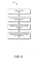
- FIG. 5 shows an example process flowchart 500 illustrating an example method for Bluetooth (BT) protection and adaptive frequency hopping (AFH).
- Process 500 may be implemented for example in block 228 of BT modem 206 described above.
- the order in which the method is described is not intended to be construed as a limitation, and any number of the described method blocks may be combined in any order to implement the method, or alternate method. Additionally, individual blocks may be deleted from the method without departing from the spirit and scope of the subject matter described herein.
- the method may be implemented in any suitable hardware, software, firmware, or a combination thereof, without departing from the scope of the invention.
- activating a BT mode of a device is performed.
- the BT modem 206 is activated to perform the BT mode of wireless communication.
- the BT modem 206 is co-running with the cellular 2G/LTE 208.
- calculating unwanted harmonic frequencies from a co-running uplink cellular transmission is performed.
- the block 228 implements an algorithm that measures and determines the unwanted harmonic frequencies due to the uplink cellular transmission from the co-running cellular 2G/LTE 208.
- AFH channel frequency negotiation is performed with BT connected peer devices.
- the AFH channel frequency negotiation may be based upon the calculated unwanted harmonic frequencies in block 504 above.
- the AFH channel includes the channel/s with no unwanted harmonic frequencies.
Landscapes
- Engineering & Computer Science (AREA)
- Computer Networks & Wireless Communication (AREA)
- Signal Processing (AREA)
- Noise Elimination (AREA)
Applications Claiming Priority (1)
| Application Number | Priority Date | Filing Date | Title |
|---|---|---|---|
| US14/571,827 US9369217B1 (en) | 2014-12-16 | 2014-12-16 | Cellular up-link harmonic spurs mitigation in Wi-Fi and bluetooth receivers |
Publications (1)
| Publication Number | Publication Date |
|---|---|
| EP3035545A1 true EP3035545A1 (en) | 2016-06-22 |
Family
ID=54695480
Family Applications (1)
| Application Number | Title | Priority Date | Filing Date |
|---|---|---|---|
| EP15194776.9A Withdrawn EP3035545A1 (en) | 2014-12-16 | 2015-11-16 | Cellular up-link harmonic spurs mitigation in wi-fi and bluetooth receivers |
Country Status (4)
| Country | Link |
|---|---|
| US (1) | US9369217B1 (zh) |
| EP (1) | EP3035545A1 (zh) |
| CN (1) | CN105703784B (zh) |
| TW (1) | TWI578718B (zh) |
Families Citing this family (4)
| Publication number | Priority date | Publication date | Assignee | Title |
|---|---|---|---|---|
| US10200070B2 (en) | 2017-01-13 | 2019-02-05 | Cypress Semiconductor Corporation | Spur cancellation system for modems |
| CN110868757B (zh) * | 2019-11-21 | 2024-04-09 | 维沃移动通信有限公司 | 一种信息的传输方法、装置及电子设备 |
| US11695445B2 (en) * | 2020-08-06 | 2023-07-04 | Samsung Electronics Co., Ltd. | Equalizer assisted polynomial based linearity enhancement and self-interference canceler |
| CN114157310B (zh) * | 2020-09-08 | 2023-07-07 | Oppo(重庆)智能科技有限公司 | 谐波滤除的方法、装置、终端及存储介质 |
Citations (1)
| Publication number | Priority date | Publication date | Assignee | Title |
|---|---|---|---|---|
| US20120178386A1 (en) * | 2011-01-07 | 2012-07-12 | Mattia Pascolini | Methods for adjusting radio-frequency circuitry to mitigate interference effects |
Family Cites Families (8)
| Publication number | Priority date | Publication date | Assignee | Title |
|---|---|---|---|---|
| CN101163291B (zh) * | 2006-10-12 | 2010-09-08 | 华为技术有限公司 | 一种为多模终端提供接入网选择的方法、系统及装置 |
| US20090190633A1 (en) * | 2008-01-24 | 2009-07-30 | Smith Francis J | Interference mitigation of signals within the same frequency spectrum |
| US8823459B2 (en) * | 2011-03-25 | 2014-09-02 | Skyworks Solutions, Inc. | Variable frequency circuit controller |
| EP2711735B1 (en) * | 2011-05-16 | 2018-10-10 | Furuno Electric Co., Ltd. | Interference wave signal removal device, gnss receiver device, mobile terminal, interference wave signal removal program, and interference wave signal removal method |
| US9667306B2 (en) * | 2011-10-26 | 2017-05-30 | Adam James Wang | Multimode multiband wireless device with broadband power amplifier |
| US20130203369A1 (en) * | 2012-02-07 | 2013-08-08 | Qualcomm Atheros, Inc. | Notch filter integrated in lna of a coexisting radio |
| US9565685B2 (en) * | 2013-08-30 | 2017-02-07 | Qualcomm Incorporated | Reverse channel switch request from stations to access points for LTE/Wi-Fi coexistence |
| US9154263B1 (en) * | 2014-03-31 | 2015-10-06 | King Fahd University Of Petroleum And Minerals | Evaluation of compressed sensing in UWB systems with NBI |
-
2014
- 2014-12-16 US US14/571,827 patent/US9369217B1/en active Active
-
2015
- 2015-11-09 CN CN201510755644.6A patent/CN105703784B/zh active Active
- 2015-11-11 TW TW104137184A patent/TWI578718B/zh not_active IP Right Cessation
- 2015-11-16 EP EP15194776.9A patent/EP3035545A1/en not_active Withdrawn
Patent Citations (1)
| Publication number | Priority date | Publication date | Assignee | Title |
|---|---|---|---|---|
| US20120178386A1 (en) * | 2011-01-07 | 2012-07-12 | Mattia Pascolini | Methods for adjusting radio-frequency circuitry to mitigate interference effects |
Also Published As
| Publication number | Publication date |
|---|---|
| CN105703784B (zh) | 2018-07-17 |
| TW201631910A (zh) | 2016-09-01 |
| CN105703784A (zh) | 2016-06-22 |
| TWI578718B (zh) | 2017-04-11 |
| US9369217B1 (en) | 2016-06-14 |
| US20160173209A1 (en) | 2016-06-16 |
Similar Documents
| Publication | Publication Date | Title |
|---|---|---|
| US8594255B2 (en) | Reception device and reception method | |
| US9160386B2 (en) | Non-linear interference cancellation across aggressor transmitters and victim receivers | |
| EP3090489B1 (en) | Method for adjusting lo frequencies in receiver and associated receiver | |
| US9584170B2 (en) | Broadband superhetrodyne receiver with agile intermediate frequency for interference mitigation | |
| WO2008145800A1 (en) | Interference mitigation | |
| US20100105345A1 (en) | Method and device for detecting presence of a carrier signal in a received signal | |
| WO2012007278A1 (en) | Synchronizing and detecting interference in wireless receiver | |
| EP3035545A1 (en) | Cellular up-link harmonic spurs mitigation in wi-fi and bluetooth receivers | |
| US8335285B2 (en) | Communication apparatus | |
| US20090268678A1 (en) | Method and apparatus for automatic gain control in a mobile orthogonal frequency division multiple access (ofdma) network | |
| US9774356B2 (en) | Method and apparatus relating to reception of radio signals | |
| US9787354B2 (en) | Pre-distortion of receive signal for interference mitigation in broadband transceivers | |
| US8750817B2 (en) | Controlling filter bandwidth based on blocking signals | |
| EP3024150B1 (en) | Accurate desensitization estimation of a receiver | |
| EP2506428B1 (en) | Technique for automatic gain control | |
| US20180287644A1 (en) | Low-if receiver | |
| JP5086193B2 (ja) | デジタル無線の受信装置 | |
| KR101047117B1 (ko) | 송신 스펙트럼 센싱장치 | |
| WO2014132310A1 (ja) | 受信装置および復調方法 |
Legal Events
| Date | Code | Title | Description |
|---|---|---|---|
| PUAI | Public reference made under article 153(3) epc to a published international application that has entered the european phase |
Free format text: ORIGINAL CODE: 0009012 |
|
| 17P | Request for examination filed |
Effective date: 20151116 |
|
| AK | Designated contracting states |
Kind code of ref document: A1 Designated state(s): AL AT BE BG CH CY CZ DE DK EE ES FI FR GB GR HR HU IE IS IT LI LT LU LV MC MK MT NL NO PL PT RO RS SE SI SK SM TR |
|
| AX | Request for extension of the european patent |
Extension state: BA ME |
|
| STAA | Information on the status of an ep patent application or granted ep patent |
Free format text: STATUS: THE APPLICATION IS DEEMED TO BE WITHDRAWN |
|
| 18D | Application deemed to be withdrawn |
Effective date: 20180602 |