EP3035101A1 - Scanning apparatus and confocal observation apparatus - Google Patents
Scanning apparatus and confocal observation apparatus Download PDFInfo
- Publication number
- EP3035101A1 EP3035101A1 EP15199858.0A EP15199858A EP3035101A1 EP 3035101 A1 EP3035101 A1 EP 3035101A1 EP 15199858 A EP15199858 A EP 15199858A EP 3035101 A1 EP3035101 A1 EP 3035101A1
- Authority
- EP
- European Patent Office
- Prior art keywords
- illumination lens
- scanning apparatus
- light
- focal plane
- reflector
- Prior art date
- Legal status (The legal status is an assumption and is not a legal conclusion. Google has not performed a legal analysis and makes no representation as to the accuracy of the status listed.)
- Withdrawn
Links
- 238000005286 illumination Methods 0.000 claims abstract description 195
- 230000003287 optical effect Effects 0.000 claims abstract description 102
- 230000007423 decrease Effects 0.000 claims abstract description 5
- 238000009987 spinning Methods 0.000 description 63
- 239000000523 sample Substances 0.000 description 33
- 210000001747 pupil Anatomy 0.000 description 12
- 238000009826 distribution Methods 0.000 description 9
- 239000013307 optical fiber Substances 0.000 description 8
- 238000003384 imaging method Methods 0.000 description 6
- 238000005516 engineering process Methods 0.000 description 5
- 238000004064 recycling Methods 0.000 description 5
- 230000010287 polarization Effects 0.000 description 4
- 239000000758 substrate Substances 0.000 description 4
- 230000000694 effects Effects 0.000 description 3
- 239000004973 liquid crystal related substance Substances 0.000 description 3
- 230000009471 action Effects 0.000 description 2
- 230000004075 alteration Effects 0.000 description 2
- 230000008901 benefit Effects 0.000 description 2
- 239000012472 biological sample Substances 0.000 description 2
- 239000011248 coating agent Substances 0.000 description 2
- 238000000576 coating method Methods 0.000 description 2
- 230000003247 decreasing effect Effects 0.000 description 2
- 230000001419 dependent effect Effects 0.000 description 2
- 230000000116 mitigating effect Effects 0.000 description 2
- 230000004048 modification Effects 0.000 description 2
- 238000012986 modification Methods 0.000 description 2
- 239000004065 semiconductor Substances 0.000 description 2
- 238000002834 transmittance Methods 0.000 description 2
- 238000004519 manufacturing process Methods 0.000 description 1
- 239000000463 material Substances 0.000 description 1
- 239000002184 metal Substances 0.000 description 1
- 229910052751 metal Inorganic materials 0.000 description 1
- 238000000034 method Methods 0.000 description 1
- 229910052710 silicon Inorganic materials 0.000 description 1
- 239000010703 silicon Substances 0.000 description 1
Images






Classifications
-
- G—PHYSICS
- G02—OPTICS
- G02B—OPTICAL ELEMENTS, SYSTEMS OR APPARATUS
- G02B21/00—Microscopes
- G02B21/0004—Microscopes specially adapted for specific applications
- G02B21/002—Scanning microscopes
- G02B21/0024—Confocal scanning microscopes (CSOMs) or confocal "macroscopes"; Accessories which are not restricted to use with CSOMs, e.g. sample holders
- G02B21/0036—Scanning details, e.g. scanning stages
- G02B21/0048—Scanning details, e.g. scanning stages scanning mirrors, e.g. rotating or galvanomirrors, MEMS mirrors
-
- G—PHYSICS
- G02—OPTICS
- G02B—OPTICAL ELEMENTS, SYSTEMS OR APPARATUS
- G02B21/00—Microscopes
- G02B21/0004—Microscopes specially adapted for specific applications
- G02B21/002—Scanning microscopes
- G02B21/0024—Confocal scanning microscopes (CSOMs) or confocal "macroscopes"; Accessories which are not restricted to use with CSOMs, e.g. sample holders
- G02B21/0032—Optical details of illumination, e.g. light-sources, pinholes, beam splitters, slits, fibers
-
- G—PHYSICS
- G02—OPTICS
- G02B—OPTICAL ELEMENTS, SYSTEMS OR APPARATUS
- G02B21/00—Microscopes
- G02B21/0004—Microscopes specially adapted for specific applications
- G02B21/002—Scanning microscopes
- G02B21/0024—Confocal scanning microscopes (CSOMs) or confocal "macroscopes"; Accessories which are not restricted to use with CSOMs, e.g. sample holders
- G02B21/0036—Scanning details, e.g. scanning stages
- G02B21/0044—Scanning details, e.g. scanning stages moving apertures, e.g. Nipkow disks, rotating lens arrays
-
- G—PHYSICS
- G02—OPTICS
- G02B—OPTICAL ELEMENTS, SYSTEMS OR APPARATUS
- G02B26/00—Optical devices or arrangements for the control of light using movable or deformable optical elements
- G02B26/08—Optical devices or arrangements for the control of light using movable or deformable optical elements for controlling the direction of light
- G02B26/0816—Optical devices or arrangements for the control of light using movable or deformable optical elements for controlling the direction of light by means of one or more reflecting elements
- G02B26/0833—Optical devices or arrangements for the control of light using movable or deformable optical elements for controlling the direction of light by means of one or more reflecting elements the reflecting element being a micromechanical device, e.g. a MEMS mirror, DMD
Definitions
- This invention relates to a scanning apparatus that scans a sample and a confocal observation apparatus that includes the scanning apparatus.
- Confocal observation apparatuses such as a confocal microscope are widely used in various fields such as a testing of a semiconductor substrate and an observation of a biological sample because they have a high resolution in a Z-axis direction and provide an excellent sectioning effect.
- a confocal microscope detects light from each point on a sample such as a substrate or a biological sample by scanning the sample, so as to obtain an image of the sample. For that reason, it includes a scanning apparatus that scans the sample.
- a scanning apparatus that scans the sample.
- a disk scanning apparatus using a disk scanning apparatus, multipoint scanning can be performed and there are fewer mechanical restrictions on a high-speed rotation of a disk.
- a sample can be scanned at high speed.
- the disk scanning apparatus a majority of incident illumination light is interrupted and wasted by the disk. As a result, an exposure time is increased in order to compensate its low illumination efficiency, and in reality, it is difficult to realize a high-speed scanning of a sample.
- Japanese Laid-open Patent Application Publication No. 04-330412 US Patent Application Publication No. 2008/0218849
- Japanese Laid-open Patent Application Publication No. 2013-015681 disclose technologies related to such a problem.
- Those three documents disclose technologies that improve an illumination efficiency of a disk scanning apparatus.
- Japanese Laid-open Patent Application Publication No. 2013-015681 discloses a mirror and a prism as means for inputting the illumination light that has been reflected on a disk into the disk again.
- the technology disclosed in this document permits, with a simple configuration, a reuse of the illumination light that would conventionally be wasted.
- a technology is needed that further improves an illumination efficiency while enjoying the benefits of the technology disclosed in this document.
- an object of the present invention is to provide a scanning apparatus that easily realizes a high illumination efficiency, a confocal observation apparatus that includes the scanning apparatus, and a disk scanning apparatus.
- An aspect of the present invention permits providing of a scanning apparatus that includes a light source, spatial light modulation means having a flat first reflection surface and modulating an incident beam of light on the first reflection surface, an illumination lens that irradiates the spatial light modulation means with a beam of light from the light source and that refracts a principal ray of the beam of light modulated by the spatial light modulation means so that an angle between the principal ray and an optical axis of the illumination lens decreases, and a first reflector that directs, toward the illumination lens, a beam of light by reflecting the beam of light multiple times between the illumination lens and a front focal plane of the illumination lens, the beam of light being modulated by the spatial light modulation means and entering through the illumination lens.
- the present invention permits providing of a scanning apparatus that easily realizes a high illumination efficiency, a confocal observation apparatus that includes the scanning apparatus, and a disk scanning apparatus.
- a fluorescent material is excited and a fluorescence is emitted.
- the fluorescence from the sample S is collected by the objective 10 and the tube lens 20 in the spinning disk 34, and only a fluorescence that has occurred from the position optically conjugate with a slit of the spinning disk 34 passes through the spinning disk 34.
- the fluorescence that has passed through the spinning disk 34 enters the imaging device 36 including a two-dimensional image sensor through the illumination lens 33, the dichroic mirror 32, and the lens 35.
- the spinning disk 34, the illumination lens 33, the dichroic mirror 32, and the reflection member 37 function as a recycling optical system that reuses a laser beam reflected on the reflection surface 34a, which will be described below. This permits a realization of a high illumination efficiency.
- the reflection member 37 is a reflector (a first reflector) that includes two flat mirrors reflecting a beam of light that has entered through the illumination lens 33.
- the reflection member 37 is arranged between the illumination lens 33 and the front focal plane FF of the illumination lens 33 so that a beam of light from the position P1 enters the illumination lens 33 passing between the two flat mirrors.
- the two flat mirrors each have a reflection surface (a reflection surface 37a and a reflection surface 37b) whose respective normal lines have directions that are 90 degrees different with respect to each other in a section along the optical axis AX of the illumination lens 33 (a YZ section of FIG. 5 ) .
- the laser beam reflected on the reflection surface 34a re-enters the spinning disk 34 and is reused. Further, the re-entrance of the laser beam is repeated unless the beam of light reflected on the reflection surface 34a and converged by the illumination lens 33 is deviated from the reflection member 37.
- a position to enter the reflection surfaces (the reflection surface 37a and the reflection surface 37b) of the reflection member 37 is shifted by 2 ⁇ D1 in a Y-axis direction every time the re-entrance is repeated when a distance between an initial entering position of the laser beam (that is, the position P1) and the optical axis AX is D1, as illustrated in FIG. 5 .
- the number of re-entrances is D2/(2 ⁇ D1) when a width of the mirrors in the Y-axis direction that constitute the reflection member 37 is D2.
- the disk scanning apparatus 30 permits a laser beam to re-enter the spinning disk 34 multiple times, which results in realizing a high illumination efficiency.
- the illumination efficiency of the disk scanning apparatus 30 as illustrated in FIGS. 6A to 6D , an about-25-to-30-times-repeated re-entrance of light permits obtaining of an illumination efficiency almost similar to when light re-enters the unlimited number of times, regardless of an disk aperture ratio.
- the disk aperture ratio is a proportion of an area of the apertures in an illuminated area to an area of the illuminated area in the disk.
- the disk scanning apparatus 30 is preferably designed so that D2/(2 ⁇ D1) is about 30.
- the present embodiment illustrates the spinning disk 34 in which the apertures (slits) and the shield portions are alternately formed at a constant pitch.
- the disk scanning apparatus 30 includes a disk in which apertures that function as a confocal aperture are formed, and the disk scanning apparatus 30 may include, for example, a so-called Nipkow disk in which pinholes are formed, instead of the spinning disk 34.
- FIG. 8 illustrates an example of a portion of a configuration of a disk scanning apparatus according to the present embodiment.
- the disk scanning apparatus according to the present embodiment is different from the disk scanning apparatus 30 according to the first embodiment in including a reflection member 40.
- the reflection member 40 has, in the front focal plane FF of the illumination lens 33, a reflection surface 40a perpendicular to the optical axis AX. The others in the configuration are similar to those of the disk scanning apparatus 30.
- the reflection surface 40a of the reflection member 40 is a third reflection surface of the disk scanning apparatus.
- an exit end of the optical fiber 31a (the position P1) is arranged on the front focal plane FF and in a position farther away than the reflection member 41 from the optical axis AX. This permits a laser beam to gradually move from outside to inside the reflection member 41 every time it re-enters the reflection member 41. Then, when getting close to the center, the laser beam moves from the inside to the outside.
- the disk scanning apparatus according to the present embodiment permits doubling of the number of re-entrances. This results in realizing a high illumination efficiency as is the case with the disk scanning apparatus according to the second embodiment. It is also similar to the disk scanning apparatus according to the second embodiment in being able to mitigate a bias in the illumination intensity distribution in the exit pupil plane of the objective 10.
- the flat mirrors When the flat mirrors are narrowly spaced with respect to each other, they may be arranged away from each other in the reflection member 41 as is the case in the reflection member 37.
- the disk scanning apparatus permits suppressing of an angular dependency of the intensity of an illumination light with which the sample S is irradiated while easily realizing a high illumination efficiency.
- FIGS. 11A and 11B illustrate an example of a portion of a configuration of a disk scanning apparatus according to the present embodiment.
- FIG. 11A is a YZ-sectional view
- FIG. 11B illustrates the portion as viewed from a Z-axis direction.
- the disk scanning apparatus according to the present embodiment is different from the disk scanning apparatus according to the second embodiment in arranging the exit end of the optical fiber 31a in the position P1 offset from the optical axis AX not only in the Y-axis direction but also in an X-axis direction.
- the others in the configuration are similar to those of the disk scanning apparatus according to the second embodiment.
- the reflection member 43 includes four flat mirrors. Two of the four flat mirrors each have a reflection surface (a reflection surface 43a and a reflection surface 43b) whose respective normal lines have directions that are 90 degrees different with respect to each other in a section along the optical axis AX. Those two reflection surfaces intersect and are in contact with each other in the front focal plane FF. Further, the remaining two flat mirrors, too, each have a reflection surface (a reflection surface 43c and a reflection surface 43d) whose respective normal lines have directions that are 90 degrees different with respect to each other in a section along the optical axis AX. Those two reflection surfaces intersect and are in contact with each other in the front focal plane FF. In other words, the reflection member 43 is constituted of two reflection member elements each including two flat mirrors.
- the reflection member 43 is arranged between the illumination lens 33 and the front focal plane FF of the illumination lens 33 so that a beam of light from the position P1 enters the illumination lens 33 passing between the two reflection member elements.
- the position P1 is a position obtained by moving from the optical axis AX by a distance D1 in a Y-direction.
- the disk scanning apparatus permits an easy realization of a high illumination efficiency and permits suppressing of an angular dependency of the intensity of an illumination light with which the sample S is irradiated.
- the disk scanning apparatus permits doubling of the number of re-entrances by providing the reflection member 40 on the front focal plane FF. Further, if the position P1 is offset from the optical axis AX not only in the Y-direction but also in an X-direction, a reflection member can be made smaller.
- the reflection member 44 is a conical mirror whose apex is in the position P1 on the front focal plane FF.
- the reflection member 44 is similar to the reflection member 37 in having two reflection surfaces (a reflection surface 44a and a reflection surface 44b) whose respective normal lines have directions that are 90 degrees different with respect to each other in a section along the optical axis AX, those two reflection surfaces intersecting with each other in the front focal plane FF.
- the reflection member 44 does not have power in a YZ-plane, but has power in an XY-plane.
- the laser beam reflected on the reflection surface 34a is not collected on one point and then a point image is not formed, but like the disk scanning apparatus 30, it permits the laser beam to re-enter the spinning disk 34 multiple times.
- the position P1 that is an initial entering position of a laser beam is a position offset by D1 from the optical axis AX of the illumination lens 33, and farther away than the front focal plane FF by ⁇ from the illumination lens 33.
- the illumination lens 33 that constitutes the 4f optical system along with the spinning disk 34 acts so that a light source image formed away than the front focal plane FF from the illumination lens 33 is projected onto a position that is closer than the front focal plane FF to the illumination lens 33.
- the illumination lens 33 and the reflection member 44 are arranged so that the light source image is formed, in a state in which the reflection member 47 is excluded, by the illumination lens 33 in a position that is closer than the front focal plane FF to the illumination lens 33.
- the reflection member 48 is a second reflector that directs, toward the illumination lens 33, the beam of light reflected on the spinning disk 34 and entering through the illumination lens 33.
- the reflection member 48 is similar to the reflection member 40 of the disk scanning apparatus according to the second embodiment in having a reflection surface (a reflection surface 48a) perpendicular to the optical axis AX, and in being arranged in a position which a laser beam deviated from the reflection member 47 as a result of re-entering the spinning disk 34 repeatedly enters. The position is farther away than the reflection member 47 from the optical axis AX. However, there is a difference in that the reflection member 48 is arranged in a position closer than the front focal plane FF to the illumination lens 33, the position is near the reflection member 47.
Landscapes
- Physics & Mathematics (AREA)
- General Physics & Mathematics (AREA)
- Optics & Photonics (AREA)
- Chemical & Material Sciences (AREA)
- Analytical Chemistry (AREA)
- Microscoopes, Condenser (AREA)
Abstract
Description
- This invention relates to a scanning apparatus that scans a sample and a confocal observation apparatus that includes the scanning apparatus.
- Confocal observation apparatuses such as a confocal microscope are widely used in various fields such as a testing of a semiconductor substrate and an observation of a biological sample because they have a high resolution in a Z-axis direction and provide an excellent sectioning effect.
- A confocal microscope detects light from each point on a sample such as a substrate or a biological sample by scanning the sample, so as to obtain an image of the sample. For that reason, it includes a scanning apparatus that scans the sample. There are various types of scanning apparatuses for a confocal microscope, and a scanning apparatus that scans a sample by modulating light in a plane optically conjugate with the sample is known. This type of scanning apparatus includes a scanner that uses a micro electro mechanical systems (MEMS) device such as a digital micromirror device (DMD) or uses a liquid crystal device, and a scanning apparatus that includes a spinning disk in which, for example, slits or pinholes are formed (hereinafter referred to as "disk scanning apparatus") is a typical example of it.
- Generally, using a disk scanning apparatus, multipoint scanning can be performed and there are fewer mechanical restrictions on a high-speed rotation of a disk. Thus, in principle, a sample can be scanned at high speed. However, in the disk scanning apparatus, a majority of incident illumination light is interrupted and wasted by the disk. As a result, an exposure time is increased in order to compensate its low illumination efficiency, and in reality, it is difficult to realize a high-speed scanning of a sample.
- For example,
Japanese Laid-open Patent Application Publication No. 04-330412 US Patent Application Publication No. 2008/0218849 , andJapanese Laid-open Patent Application Publication No. 2013-015681 -
Japanese Laid-open Patent Application Publication No. 04-330412 US Patent Application Publication No. 2008/0218849 disclose a microlens array or a micromirror as means for collecting an illumination light on pinholes (apertures) formed in a disk. However, an advanced technique is needed to manufacture such means and to incorporate it into a device. -
Japanese Laid-open Patent Application Publication No. 2013-015681 - In light of the problem described above, an object of the present invention is to provide a scanning apparatus that easily realizes a high illumination efficiency, a confocal observation apparatus that includes the scanning apparatus, and a disk scanning apparatus.
- An aspect of the present invention permits providing of a scanning apparatus that includes a light source, spatial light modulation means having a flat first reflection surface and modulating an incident beam of light on the first reflection surface, an illumination lens that irradiates the spatial light modulation means with a beam of light from the light source and that refracts a principal ray of the beam of light modulated by the spatial light modulation means so that an angle between the principal ray and an optical axis of the illumination lens decreases, and a first reflector that directs, toward the illumination lens, a beam of light by reflecting the beam of light multiple times between the illumination lens and a front focal plane of the illumination lens, the beam of light being modulated by the spatial light modulation means and entering through the illumination lens.
- Another aspect of the present invention permits providing of a confocal observation apparatus that includes the scanning apparatus according to the above-mentioned aspect and an objective, the scanning apparatus including the first reflection surface in a plane optically conjugate with a front focal plane of the objective.
- The present invention permits providing of a scanning apparatus that easily realizes a high illumination efficiency, a confocal observation apparatus that includes the scanning apparatus, and a disk scanning apparatus.
- The present invention will be more apparent from the following detailed description when the accompanying drawings are referenced.
-
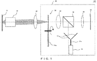
FIG. 1 illustrates an example of a configuration of a confocal microscope according to a first embodiment of the present invention; -
FIG. 2 illustrates an example of a configuration of a spinning disk ofFIG. 1 ; -
FIG. 3 illustrates an action of an illumination lens in a disk scanning apparatus according to the first embodiment; -
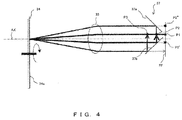
FIG. 4 illustrates a positional relationship between a spinning disk, the illumination lens, and a reflection member in the disk scanning apparatus according to the first embodiment; -
FIG. 5 illustrates the reflection member that is included in the disk scanning apparatus according to the first embodiment; -
FIGS. 6A to 6D illustrate a relationship between a utilization efficiency and the number of entrances of an illumination light; -
FIG. 7 illustrates a modification of the reflection member that is included in the disk scanning apparatus according to the first embodiment; -
FIG. 8 illustrates an example of a portion of a configuration of a disk scanning apparatus according to a second embodiment of the present invention; -
FIG. 9 illustrates an example of a portion of a configuration of a disk scanning apparatus according to a third embodiment of the present invention; -
FIG. 10 illustrates an example of a portion of a configuration of a disk scanning apparatus according to a fourth embodiment of the present invention; -
FIGS. 11A and 11B illustrate an example of a portion of a configuration of a disk scanning apparatus according to a fifth embodiment of the present invention.FIGS. 11A and 11B illustrate the portion as viewed from directions different from each other; -
FIGS. 12A and 12B illustrate an example of a portion of a configuration of a disk scanning apparatus according to a sixth embodiment of the present invention.FIGS. 12A and 12B illustrate the portion as viewed from directions different from each other; -
FIG. 13 illustrates an example of a portion of a configuration of a disk scanning apparatus according to a seventh embodiment of the present invention; -
FIG. 14 illustrates an example of a portion of a configuration of a disk scanning apparatus according to an eighth embodiment of the present invention; -
FIG. 15 illustrates a positional relationship between the spinning disk, the illumination lens, and the reflection member in a disk scanning apparatus according to a ninth embodiment of the present invention; -
FIG. 16 illustrates the reflection member included in the disk scanning apparatus according to the ninth embodiment; -
FIG. 17 illustrates an example of a configuration of a confocal microscope according to a tenth embodiment of the present invention; -
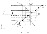
FIG. 18 illustrates an example of a portion of a configuration of a disk scanning apparatus according to an eleventh embodiment of the present invention; -
FIGS. 19A to 19D illustrate positional relationships between a front focal plane of a 4f optical system and a light source image position.FIGS. 19A to 19D illustrate relationships for the numbers of recycles that are different from one another; -
FIG. 20 illustrates an example of a modified positional relationship between a front focal position FF and the initial entering position illustrated inFIG. 18 ; -
FIGS. 21A and 21B illustrate an example of a portion of a configuration of a disk scanning apparatus according to a twelfth embodiment of the present invention.FIGS. 21A and 21B illustrate the portion as viewed from directions different from each other; -
FIGS. 22A and 22B illustrate an example of a portion of a configuration of a disk scanning apparatus according to a thirteenth embodiment of the present invention.FIGS. 22A and 22B illustrate the portion as viewed from directions different from each other; -
FIG. 23 illustrates an example of a configuration of a confocal microscope according to a fourteenth embodiment of the present invention; -
FIG. 24 illustrates an example of a configuration of a confocal microscope according to a fifteenth embodiment of the present invention; and -
FIGS. 25A to 25C illustrate examples of configurations of reflectors. -
FIG. 1 illustrates an example of a configuration of aconfocal microscope 100 according to the present embodiment. Theconfocal microscope 100 is a disk scanning confocal observation apparatus that includes adisk scanning apparatus 30, and is a fluorescence microscope that detects a fluorescence from a sample S to obtain an image of the sample S. Theconfocal microscope 100 further includes an objective 10 and atube lens 20 between the sample S and thedisk scanning apparatus 30. - The
disk scanning apparatus 30 includes alight source 31, adichroic mirror 32, anillumination lens 33, aspinning disk 34, alens 35, animaging device 36, and areflection member 37. - The
light source 31 is, for example, a laser. A laser beam emitted from thelight source 31 enters thedichroic mirror 32 through anoptical fiber 31a. Thedichroic mirror 32 is a light separating element on which a laser beam from thelight source 31 is reflected and through which a fluorescence from the sample S is transmitted. Thespinning disk 34 is irradiated with the laser beam reflected on thedichroic mirror 32. - The
spinning disk 34 is, for example, a rotary disk in which apertures (slits) and shield portions are alternatively formed at a constant pitch, as illustrated inFIG. 2 , and has aflat reflection surface 34a on thelight source 31 side. Thespinning disk 34 illustrated inFIG. 2 includes an area A1 and an area A2 whose respective apertures are formed in directions that are longitudinally different from each other, and the apertures are represented by white lines. Thereflection surface 34a is formed by coating with a metal or dielectric film on a substrate of thespinning disk 34, so as to enhance the reflectance with respect to a laser beam. Thespinning disk 34 is arranged in a plane optically conjugate with the sample S, that is, in a plane optically conjugate with the front focal plane of the objective 10 (the focal plane on the sample S side) . - A portion of the laser beam that has entered the
spinning disk 34 enters a slit formed in thespinning disk 34 and passes through thespinning disk 34. The rest of the laser beam is reflected on thereflection surface 34a. A position on the sample S that is optically conjugate with the slit is irradiated, by thetube lens 20 and the objective 10, with the laser beam that has passed through thespinning disk 34. - In the sample S irradiated with the laser beam, a fluorescent material is excited and a fluorescence is emitted. The fluorescence from the sample S is collected by the objective 10 and the
tube lens 20 in thespinning disk 34, and only a fluorescence that has occurred from the position optically conjugate with a slit of thespinning disk 34 passes through thespinning disk 34. The fluorescence that has passed through thespinning disk 34 enters theimaging device 36 including a two-dimensional image sensor through theillumination lens 33, thedichroic mirror 32, and thelens 35. - The
imaging device 36 is, for example, a CCD (charge-coupled device) camera that includes a CCD image sensor. Theimaging device 36 is arranged in a plane optically conjugate with the sample S. In other words, in theconfocal microscope 100, the sample S, thespinning disk 34, and theimaging device 36 are arranged in positions optically conjugate with one another. Thus, in theconfocal microscope 100, it is possible to scan the sample S to obtain a fluorescent image of the sample S by a position of a slit is changed with the rotation of thespinning disk 34. - Further, in the
disk scanning apparatus 30 and theconfocal microscope 100, thespinning disk 34, theillumination lens 33, thedichroic mirror 32, and thereflection member 37 function as a recycling optical system that reuses a laser beam reflected on thereflection surface 34a, which will be described below. This permits a realization of a high illumination efficiency. - Reuse of a laser beam in the
disk scanning apparatus 30 will now be described in detail with reference toFIGS. 3 to 5 .FIG. 3 illustrates an action of theillumination lens 33.FIG. 3 illustrates an illumination optical system in thedisk scanning apparatus 30, from which thedichroic mirror 32 and thereflection member 37 have been excluded. - In the
disk scanning apparatus 30, thereflection surface 34a of thespinning disk 34 is located in a back focal plane FB of theillumination lens 33. A light source image of thelight source 31 is formed in a position P1 that is on a front focal plane FF of theillumination lens 33 and is offset from an optical axis AX of theillumination lens 33. Further, the optical axis AX of theillumination lens 33, a normal line NL of thereflection surface 34a of thespinning disk 34, and a principal ray Lp of a beam of light L from the position P1 are parallel. - Thus, the
illumination lens 33 acts as follows. First, theillumination lens 33 converts a beam of light L from the position P1 (including a principal ray Lp and a marginal ray Lm) into a collimated beam that is inclined with respect to the normal line NL of thereflection surface 34a, and irradiates thespinning disk 34 with the collimated beam. Further, theillumination lens 33 refracts a principal ray of the collimated beam reflected on thereflection surface 34a without passing through thespinning disk 34, so that an angle between the principal ray and an optical axis AX of theillumination lens 33 decreases. More specifically, theillumination lens 33 refracts a principal ray in a direction parallel with the optical axis AX. As a result of the refraction, to the principal ray collect in a position P2 that is on the front focal plane FF and is offset from the optical axis AX. Here, theillumination lens 33 is preferably arranged so as to be a substantially telecentric optical system. In this case, theillumination lens 33 does not have to be a strictly telecentric optical system, and it is sufficient if theillumination lens 33 permits light to enter thereflection surface 34a at least multiple times. - In concrete terms, the
illumination lens 33 acts so that thespinning disk 34 is irradiated with a beam of light from a light source image formed on the front focal plane FF and that the light source image formed in the front focal plane FF is projected onto a different position on the front focal plane FF. In other words, theillumination lens 33 and thespinning disk 34 are arranged, in a state in which thereflection member 37 is excluded, so that the light source image is formed by theillumination lens 33 in the front focal plane FF. - The size of an area to be illuminated in the spinning disk 34 (an area to be irradiated with a laser beam) is dependent on a numerical aperture (NA) in the position P1 and a focal length of the
illumination lens 33. Thus, preferably, the NA in the position P1 is not less than a value obtained by dividing a diameter of an area in thespinning disk 34 that has to be illuminated (hereinafter referred to as "illumination target area") by the focal length of theillumination lens 33. Further, preferably, the NA is not excessively large so as not to illuminate an area that does not have to be illuminated. -
FIG. 4 illustrates a positional relationship between thespinning disk 34, theillumination lens 33, and thereflection member 37.FIG. 5 illustrates thereflection member 37. A principal ray that is representative of a beam of light from the position P1 is illustrated inFIGS. 4 and5 . - The
reflection member 37 is a reflector (a first reflector) that includes two flat mirrors reflecting a beam of light that has entered through theillumination lens 33. Thereflection member 37 is arranged between theillumination lens 33 and the front focal plane FF of theillumination lens 33 so that a beam of light from the position P1 enters theillumination lens 33 passing between the two flat mirrors. The two flat mirrors each have a reflection surface (areflection surface 37a and areflection surface 37b) whose respective normal lines have directions that are 90 degrees different with respect to each other in a section along the optical axis AX of the illumination lens 33 (a YZ section ofFIG. 5 ) . More specifically, the two reflection surfaces each have a normal line, the respective normal lines being perpendicular to each other, and each of the normal lines of the two reflection surfaces forms a 45-degree angle with the optical axis AX. Further, two planes (aplane 38a and aplane 38b) defined by those two reflection surfaces intersect with each other in the front focal plane FF of theillumination lens 33. In this case, a position in which the two planes intersect with each other is the same as the position P1. A plane defined by a reflection surface is a plane that includes that reflection surface. Further, thereflection surface 34a of thespinning disk 34 is a first reflection surface of thedisk scanning apparatus 30 and the two reflection surfaces of thereflection member 37 are two second reflection surfaces of thedisk scanning apparatus 30. - The collimated beam reflected on the
reflection surface 34a without passing through thespinning disk 34 is converted by theillumination lens 33 into a convergent beam that is parallel with the optical axis AX. After that, the convergent beam is reflected on thereflection surface 37b before it is collected in a position P2' on the front focal plane FF, and is collected in the position P2 to form a light source image before it is reflected on thereflection surface 37a. A beam of light from the position P2 is reflected on thereflection surface 37a in a direction parallel with the optical axis AX and enters theillumination lens 33. Thereflection member 37 is arranged so that the light source image is formed by theillumination lens 33 in a position (the position P2) that is optically equivalent to the front focal plane FF. Thus, the beam of light from the position P2 is converted again into a collimated beam by theillumination lens 33 and enters thespinning disk 34 because it is equivalent to a beam of light from a position P2" on the front focal plane FF. The position P1 and the position P2 are hereinafter referred to as "light source image position", and the position P2' and the position P2" are hereinafter referred to as "pseudo light source image position". Further, a light source image, such as a light source image formed in the position P2', which is formed in a state in which thereflection member 37 is excluded is referred to as "first image", and a light source image, such as a light source image formed in the position P2, which is actually formed is referred to as "second image". A light source image that is formed in the same position in spite of the presence or absence of thereflection member 37 is a first image and a second image. - In other words, the
reflection member 37 directs, toward theillumination lens 33, the beam of light reflected on thereflection surface 34a and entering through theillumination lens 33, by reflecting the beam of light between theillumination lens 33 and the front focal plane FF of theillumination lens 33 multiple times, so that the beam of light is converted by theillumination lens 33 into a collimated beam. More specifically, thereflection member 37 converts the incident beam of light into a divergent beam that has an inverted travelling direction and has been shifted in a direction perpendicular to the optical axis AX. - As a result, in the
disk scanning apparatus 30, the laser beam reflected on thereflection surface 34a re-enters thespinning disk 34 and is reused. Further, the re-entrance of the laser beam is repeated unless the beam of light reflected on thereflection surface 34a and converged by theillumination lens 33 is deviated from thereflection member 37. In thedisk scanning apparatus 30, a position to enter the reflection surfaces (thereflection surface 37a and thereflection surface 37b) of thereflection member 37 is shifted by 2×D1 in a Y-axis direction every time the re-entrance is repeated when a distance between an initial entering position of the laser beam (that is, the position P1) and the optical axis AX is D1, as illustrated inFIG. 5 . Thus, the number of re-entrances is D2/(2×D1) when a width of the mirrors in the Y-axis direction that constitute thereflection member 37 is D2. For example, when thedisk scanning apparatus 30 is designed when D1=0.25 mm and D2=10 mm, the beam of light from the position P1 re-enters thespinning disk 34 twenty times. - Thus, the
disk scanning apparatus 30 permits a laser beam to re-enter thespinning disk 34 multiple times, which results in realizing a high illumination efficiency. Regarding the illumination efficiency of thedisk scanning apparatus 30, as illustrated inFIGS. 6A to 6D , an about-25-to-30-times-repeated re-entrance of light permits obtaining of an illumination efficiency almost similar to when light re-enters the unlimited number of times, regardless of an disk aperture ratio. The disk aperture ratio is a proportion of an area of the apertures in an illuminated area to an area of the illuminated area in the disk. Thus, thedisk scanning apparatus 30 is preferably designed so that D2/(2×D1) is about 30. -
FIGS. 6A to 6D illustrate a relationship between a utilization efficiency of an illumination light and the number of entrances of an illumination light when a disk aperture ratio is 1%, 2%, 5%, or 10%. A dashed line represents an illumination efficiency when the light enters the unlimited number of times, that is, a limiting illumination efficiency of thedisk scanning apparatus 30, and a solid line represents the utilization efficiency in thedisk scanning apparatus 30 for each number of re-entrances. InFIGS. 6A to 6D , the illumination efficiency (a utilization efficiency of an illumination light) of thedisk scanning apparatus 30 is calculated under the following conditions: - Reflectance of the spinning disk 34 (the
reflection surface 34a) RDISK=99% - Reflectance of the dichroic mirror 32 RDM=99%
- Reflectance of the reflection member 37 (the
reflection surface 37a and thereflection surface 37b) RMIRROR=99% - Transmittance of the illumination lens 33 TLENS=98% Re-entrance ratio r=91.3% (=RDISK×RDM 2×TLENS 2×RMIRROR 2)
- Higher reflectance of the spinning disk 34 RDISK, higher reflectance of the dichroic mirror 32 RDM, higher reflectance of the reflection member 37 RMIRROR, and higher transmittance of the illumination lens 33 TLENS are more desirable. The reason is that, if these are higher, a higher illumination efficiency can be realized in the
disk scanning apparatus 30. - The present embodiment illustrates an example in which the
reflection surface 34a is located in the back focal plane FB of theillumination lens 33. However, it is sufficient if thereflection surface 34a is arranged in the back focal plane FB of theillumination lens 33 or in the proximity of the back focal plane FB. When thereflection surface 34a is located at a great distance from the back focal plane FB of theillumination lens 33, a collimated beam reflected on thereflection surface 34a is converted by theillumination lens 33 into a beam of light that has a large angle with respect to the optical axis AX. The beam of light having a large angle with respect to the optical axis AX is easily deviated from thereflection member 37. On the other hand, when thereflection surface 34a is arranged in the back focal plane FB of theillumination lens 33 or in the proximity of the back focal plane FB, the collimated beam reflected on thereflection surface 34a is refracted by theillumination lens 33 so that an angle between a principal ray of the collimated beam and the optical axis AX decreases. As a result, the collimated beam is converted into a beam of light whose principal ray has a small angle with respect to the optical axis AX. In other words, the collimated beam reflected on thereflection surface 34a is converted in a substantially telecentric manner. This permits a realization of a predetermined-number-of-times repetition without being deviated from thereflection member 37. - When the
reflection surface 34a is arranged in the back focal plane FB of theillumination lens 33, a laser beam repeatedly enters the same area of thespinning disk 34. Thus, an area to be illuminated is constant. In this case, the laser beam reflected on thereflection surface 34a enters thereflection surface 34a again without entering a slit. However, in reality, the laser beam does not enter exactly the same area due to an effect of aberrations of an optical system and the like. Thus, even when thereflection surface 34a is arranged in the back focal plane FB of thereflection surface 34a, an illumination efficiency is improved. In order to realize a higher illumination efficiency, thereflection surface 34a is preferably arranged in the proximity of the back focal plane FB. - Further, the present embodiment illustrates an example in which the
plane 38a and theplane 38b intersect with each other in the front focal plane FF of theillumination lens 33. However, it is sufficient if theplane 38a and theplane 38b intersect with each other in the front focal plane FF of theillumination lens 33 or in the proximity of the front focal plane FF. In this case, "in the proximity of the front focal plane FF" refers to "within a focal depth defined by an NA in the position P1. When theplane 38a and theplane 38b intersect with each other within the focal depth from the front focal plane FF, the pseudo light source image positions (the position P2' and the position P2") are also located within the focal depth from the front focal plane FF. This permits thereflection member 37 to direct an incident beam of light toward theillumination lens 33 so that the beam of light is converted into a collimated beam by theillumination lens 33. - As described above, in the
disk scanning apparatus 30, a recycling optical system can be arranged without any precise alignment. Thus, thedisk scanning apparatus 30 permits an easy realization of a high illumination efficiency without any complicated adjustment. - Further, the present embodiment illustrates the
spinning disk 34 in which the apertures (slits) and the shield portions are alternately formed at a constant pitch. However, it is sufficient if thedisk scanning apparatus 30 includes a disk in which apertures that function as a confocal aperture are formed, and thedisk scanning apparatus 30 may include, for example, a so-called Nipkow disk in which pinholes are formed, instead of thespinning disk 34. - Further, in the present embodiment, the front focal plane FF of the
illumination lens 33 is projected onto an exit pupil plane (a back focal plane) of the objective 10. Thus, the light source images (the position P1 and the position P2) and the pseudo light source images (the position P2' and the position P2"), too, are projected onto the exit pupil plane of the objective 10, but when they are projected onto outside the pupil diameter of the objective 10, vignetting occurs in the objective 10, which results in decreasing an illumination efficiency. Therefore, thereflection member 37 preferably has a size not greater than a value obtained by dividing the pupil diameter of the objective 10 by a projection magnification from the front focal plane FF to the exit pupil plane. The reason is that a range in which a light source image and a pseudo light source image are formed is dependent on the size of thereflection member 37. Further, in order to ensure an NA for illumination as large as possible, thereflection member 37 preferably has a size similar to the value obtained by dividing the pupil diameter by the projection magnification. - Furthermore, the present embodiment illustrates an example of forming a light source image by arranging an exit end of an optical fiber in the position P1, but the
confocal microscope 100 may include a light source itself in the position P1. The light source image formed in the position P1 or the light source is preferably a point light source. The front focal plane FF of theillumination lens 33 is projected by theillumination lens 33 and thetube lens 20 onto the pupil plane of the objective 10 at a projection magnification not greater than 1×. This permits suppressing of the light amount loss caused by the vignetting in the objective 10. - Moreover, the present embodiment illustrates the
reflection member 37 formed by two flat mirrors, but thedisk scanning apparatus 30 may include aprism 39 illustrated inFIG. 7 instead of thereflection member 37. Theprism 39 has two reflection surfaces (areflection surface 39a and areflection surface 39b) whose respective normal lines have directions that are 90 degrees different with respect to each other in a section along the optical axis AX of the illumination lens 33 (the YZ section ofFIG. 7 ). Two planes defined by those two reflection surfaces intersect with each other in the front focal plane FF of theillumination lens 33. -
FIG. 8 illustrates an example of a portion of a configuration of a disk scanning apparatus according to the present embodiment. The disk scanning apparatus according to the present embodiment is different from thedisk scanning apparatus 30 according to the first embodiment in including areflection member 40. Thereflection member 40 has, in the front focal plane FF of theillumination lens 33, areflection surface 40a perpendicular to the optical axis AX. The others in the configuration are similar to those of thedisk scanning apparatus 30. Thereflection surface 40a of thereflection member 40 is a third reflection surface of the disk scanning apparatus. - The
reflection member 40 is a second reflector that directs, toward theillumination lens 33, the beam of light reflected on thereflection surface 34a and entering through theillumination lens 33. Thereflection member 40 is arranged in a position on the front focal plane FF which a laser beam deviated from thereflection member 37 as a result of re-entering thespinning disk 34 repeatedly enters. Further, thereflection member 40 is arranged in a position farther away than thereflection member 37 from the optical axis AX. The beam of light entering thereflection member 40 is reflected on thereflection surface 40a, and its travelling direction is inverted. This permits the laser beam to further re-enter thespinning disk 34 the same number of times as before it entered thereflection member 40. - Thus, compared with the
disk scanning apparatus 30, the disk scanning apparatus according to the present embodiment permits doubling of the number of re-entrances. This results in realizing an illumination efficiency higher than that of thedisk scanning apparatus 30. Thereflection member 40 may be arranged in the proximity of the front focal plane FF for the reason similar to the reason that it is sufficient if theplane 38a and theplane 38b intersect with each other in or in the proximity of the front focal plane FF. Further, the direction in which a beam of light with which thespinning disk 34 is irradiated by theillumination lens 33 is inclined with respect to the optical axis AX is inverted before and after a fold-reflection on thereflection member 40. This permits a mitigation of a bias in the illumination intensity distribution in the exit pupil plane of the objective 10. -
FIG. 9 illustrates an example of a portion of a configuration of a disk scanning apparatus according to the present embodiment. The disk scanning apparatus according to the present embodiment is different from thedisk scanning apparatus 30 according to the first embodiment in including areflection member 41 instead of thereflection member 37 and in introducing a laser beam from outside thereflection member 37. The others in the configuration are similar to those of thedisk scanning apparatus 30. - The
reflection member 41 is similar to thereflection member 37 in including two flat mirrors and in that the two flat mirrors each have a reflection surface (areflection surface 41a and areflection surface 41b) whose respective normal lines have directions that are 90 degrees different with respect to each other in a section along the optical axis AX of the illumination lens 33 (the YZ section ofFIG. 9 ). However, it is different from thereflection member 37 in that those two reflection surfaces intersect and are in contact with each other in the front focal plane FF of theillumination lens 33. - As illustrated in
FIG. 9 , in the disk scanning apparatus according to the present embodiment, an exit end of theoptical fiber 31a (the position P1) is arranged on the front focal plane FF and in a position farther away than thereflection member 41 from the optical axis AX. This permits a laser beam to gradually move from outside to inside thereflection member 41 every time it re-enters thereflection member 41. Then, when getting close to the center, the laser beam moves from the inside to the outside. - Thus, compared with the
disk scanning apparatus 30, the disk scanning apparatus according to the present embodiment permits doubling of the number of re-entrances. This results in realizing a high illumination efficiency as is the case with the disk scanning apparatus according to the second embodiment. It is also similar to the disk scanning apparatus according to the second embodiment in being able to mitigate a bias in the illumination intensity distribution in the exit pupil plane of the objective 10. When the flat mirrors are narrowly spaced with respect to each other, they may be arranged away from each other in thereflection member 41 as is the case in thereflection member 37. -
FIG. 10 illustrates an example of a portion of a configuration of a disk scanning apparatus according to the present embodiment. The disk scanning apparatus according to the present embodiment is different from thedisk scanning apparatus 30 in splitting theoptical fiber 31a halfway so as to arrange exit ends in two locations, in a position P1a and a position P1b. The others in the configuration are similar to those of thedisk scanning apparatus 30. - A laser beam from the position P1a gradually moves from inside to outside the
reflection member 37 every time it re-enters thereflection member 37. Thus, the amount of light that enters a slit at a small angle and is transmitted through thespinning disk 34 is larger than the amount of light that enters the slit at a large angle and is transmitted through thespinning disk 34. On the other hand, a laser beam from the position P1b gradually moves from outside to inside thereflection member 37 every time it re-enters thereflection member 37. Thus, the amount of light that enters a slit at a large angle and is transmitted through thespinning disk 34 is larger than the amount of light that enters the slit at a small angle and is transmitted through thespinning disk 34. This permits the illumination intensity distribution in the exit pupil plane of the objective 10 to approximate a distribution more symmetrical with respect to an optical axis of objective 10, compared to the cases of the disk scanning apparatuses according to the second and third embodiments. - Thus, the disk scanning apparatus according to the present embodiment permits suppressing of an angular dependency of the intensity of an illumination light with which the sample S is irradiated while easily realizing a high illumination efficiency.
-
FIGS. 11A and 11B illustrate an example of a portion of a configuration of a disk scanning apparatus according to the present embodiment.FIG. 11A is a YZ-sectional view, andFIG. 11B illustrates the portion as viewed from a Z-axis direction. The disk scanning apparatus according to the present embodiment is different from the disk scanning apparatus according to the second embodiment in arranging the exit end of theoptical fiber 31a in the position P1 offset from the optical axis AX not only in the Y-axis direction but also in an X-axis direction. The others in the configuration are similar to those of the disk scanning apparatus according to the second embodiment. - The position (the position P2') in which a laser beam that reflected on the
reflection surface 34a enters areflection member 42, too, varies both in the X-axis and Y-axis directions because the position (the position P1) in which a light source image is formed is offset from the optical axis AX both in the X-axis and Y-axis directions. In other words, a shift amount is shared in the X-axis and Y-axis directions. This permits a realization of the same number of re-entrances as that with thedisk scanning apparatus 30 using flat mirrors smaller than those used in thedisk scanning apparatus 30. - White circles (the position P2', a position P3', a position P4', and a position P5') illustrated in
FIG. 11B represent a n incident position at which a laser beam is incident on the reflectingsurface 42b or thereflection surface 40a. Further, black circles (the position P2", a position P3", and a position P4") represent an incident position at which a laser beam is incident on the reflectingsurface 42a. However, the black circle illustrated in the position P1 represents a position of the exit end of theoptical fiber 31a. - Thus, the disk scanning apparatus according to the present embodiment permits an easy realization of a high illumination efficiency, as is the case in the disk scanning apparatus according to the second embodiment. Further, a reflection member can be made smaller.
-
FIGS. 12A and 12B illustrate an example of a portion of a configuration of a disk scanning apparatus according to the present embodiment.FIG. 12A is the YZ-sectional view, andFIG. 12B illustrates the portion as viewed from the Z-axis direction. The disk scanning apparatus according to the present embodiment is different from the disk scanning apparatus according to the fifth embodiment in splitting theoptical fiber 31a halfway so as to arrange exit ends in two locations, in the position P1a and the position P1b. The others in the configuration are similar to those of the disk scanning apparatus according to the fifth embodiment. - The position P1a is the same as the position P1 of the fifth embodiment. The position P1b is a position offset from the
reflection surface 40a in the X-axis direction. - Thus, like the disk scanning apparatus according to the fourth embodiment, the disk scanning apparatus according to the present embodiment permits an easy realization of a high illumination efficiency and permits suppressing of an angular dependency of the intensity of an illumination light with which the sample S is irradiated. Further, as is the case in the disk scanning apparatus according to the fifth embodiment, a reflection member can be made smaller.
-
FIG. 13 illustrates an example of a portion of a configuration of a disk scanning apparatus according to the present embodiment. The disk scanning apparatus according to the present embodiment is different from thedisk scanning apparatus 30 in including areflection member 43 instead of thereflection member 37. The others in the configuration are similar to those of thedisk scanning apparatus 30. - The
reflection member 43 includes four flat mirrors. Two of the four flat mirrors each have a reflection surface (areflection surface 43a and areflection surface 43b) whose respective normal lines have directions that are 90 degrees different with respect to each other in a section along the optical axis AX. Those two reflection surfaces intersect and are in contact with each other in the front focal plane FF. Further, the remaining two flat mirrors, too, each have a reflection surface (areflection surface 43c and areflection surface 43d) whose respective normal lines have directions that are 90 degrees different with respect to each other in a section along the optical axis AX. Those two reflection surfaces intersect and are in contact with each other in the front focal plane FF. In other words, thereflection member 43 is constituted of two reflection member elements each including two flat mirrors. - Further, the
reflection member 43 is arranged between theillumination lens 33 and the front focal plane FF of theillumination lens 33 so that a beam of light from the position P1 enters theillumination lens 33 passing between the two reflection member elements. The position P1 is a position obtained by moving from the optical axis AX by a distance D1 in a Y-direction. - In the disk scanning apparatus according to the present embodiment, a laser beam reflected on the
reflection surface 34a sequentially enters the two reflection member elements. Then, in one of the reflection member elements, the laser beam moves toward a direction farther away from the optical axis AX every time it enters. In the other reflection member element, the laser beam moves toward a direction closer to the optical axis AX every time it enters. In other words, the laser beam repeats the moves toward the direction farther away from the optical axis AX and toward the direction closer to the optical axis AX in an alternate manner. This permits the illumination intensity distribution in the exit pupil plane of the objective 10 to approximate a distribution more symmetrical about the optical axis of the objective 10. - Thus, the disk scanning apparatus according to the present embodiment permits an easy realization of a high illumination efficiency and permits suppressing of an angular dependency of the intensity of an illumination light with which the sample S is irradiated.
- The disk scanning apparatus according to the present embodiment, too, permits doubling of the number of re-entrances by providing the
reflection member 40 on the front focal plane FF. Further, if the position P1 is offset from the optical axis AX not only in the Y-direction but also in an X-direction, a reflection member can be made smaller. -
FIG. 14 illustrates an example of a portion of a configuration of a disk scanning apparatus according to the present embodiment. The disk scanning apparatus according to the present embodiment is different from thedisk scanning apparatus 30 in including areflection member 44 instead of thereflection member 37. The others in the configuration are similar to those of thedisk scanning apparatus 30. - The
reflection member 44 is a conical mirror whose apex is in the position P1 on the front focal plane FF. Thereflection member 44 is similar to thereflection member 37 in having two reflection surfaces (areflection surface 44a and areflection surface 44b) whose respective normal lines have directions that are 90 degrees different with respect to each other in a section along the optical axis AX, those two reflection surfaces intersecting with each other in the front focal plane FF. However, thereflection member 44 does not have power in a YZ-plane, but has power in an XY-plane. Thus, in the disk scanning apparatus according to the present embodiment, the laser beam reflected on thereflection surface 34a is not collected on one point and then a point image is not formed, but like thedisk scanning apparatus 30, it permits the laser beam to re-enter thespinning disk 34 multiple times. - Thus, the disk scanning apparatus according to the present embodiment, too, permits an easy realization of a high illumination efficiency.
-
FIG. 15 illustrates a positional relationship between aspinning disk 45, theillumination lens 33, and areflection member 46 in a disk scanning apparatus according to the present embodiment.FIG. 16 illustrates thereflection member 46. - The disk scanning apparatus according to the present embodiment is different from the disk scanning apparatus according to the second embodiment in including the
spinning disk 45 instead of thespinning disk 34, in including thereflection member 46 instead of thereflection member 37, and in introducing a laser beam from on the optical axis AX. - The
spinning disk 45 is different from thespinning disk 34 in that a normal line NL of areflection surface 45a is inclined with respect to the optical axis AX of theillumination lens 33. A line NL' traces the normal line NL, and is a line that is parallel with the optical axis AX and formed by refracting the normal line NL at theillumination lens 33. - The
reflection member 46 is similar to thereflection member 37 in including two flat mirrors each having a reflection surface (areflection surface 46a and areflection surface 46b) whose respective normal lines have directions that are 90 degrees different with respect to each other in a section along the optical axis AX. Further, thereflection member 46 is similar to thereflection member 37 in that two planes defined by those two reflection surfaces intersect with each other in the front focal plane FF of theillumination lens 33. However, thereflection member 46 is different from thereflection member 37 in that the two planes defined by those two reflection surfaces intersect with each other on the optical axis AX. - The
reflection member 46 directs, toward theillumination lens 33, the beam of light reflected on thereflection surface 45a and entering through theillumination lens 33, by reflecting the beam of light multiple times, so that the beam of light is converted into a collimated beam by theillumination lens 33. More specifically, thereflection member 46 converts the incident beam of light into a beam of light that has an inverted travelling direction and has been shifted in a direction perpendicular to the optical axis AX. A shift amount is 2×D1 when a distance between an entering position of a laser beam (that is, the position P1) and the line NL' is D1. - Thus, like the
disk scanning apparatus 30 according to the second embodiment, the disk scanning apparatus according to the present embodiment, too, permits an easy realization of a high illumination efficiency. -
FIG. 17 illustrates an example of a configuration of aconfocal microscope 200 according to the present embodiment. Theconfocal microscope 200 according to the present embodiment is a disk scanning confocal observation apparatus that includes adisk scanning apparatus 50, and is an industrial microscope that is used, for example, for testing a semiconductor substrate. - The
confocal microscope 200 is different from theconfocal microscope 100 in including thedisk scanning apparatus 50 instead of thedisk scanning apparatus 30, and in including a λ/4plate 60 between the objective 10 and thetube lens 20. Thedisk scanning apparatus 50 is different from thedisk scanning apparatus 30 in including, instead of thedichroic mirror 32, a polarization beam splitter (PBS) 51 that is a light separating element separating an S-polarized light and a P-polarized light. - In the
confocal microscope 200, a polarized light that has a specific polarization direction (for example, an S-) in laser beams from thelight source 31 is reflected on thePBS 51, and is emitted from thedisk scanning apparatus 50. Then, a laser beam emitted from thedisk scanning apparatus 50 passes through the λ/4plate 60 twice until light reflected on the sample S enters thedisk scanning apparatus 50 again. Thus, the laser beam enters theimaging device 36 passing through thePBS 51 because it enters thePBS 51 as a P-polarized light. - The
disk scanning apparatus 50 and theconfocal microscope 200 permit providing of an advantage similar to that provided by thedisk scanning apparatus 30 and theconfocal microscope 100, that is, they permit an easy realization of a high illumination efficiency. -
FIG. 18 illustrates an example of a portion of a configuration of a disk scanning apparatus according to the present embodiment.FIGS. 19A to 19D illustrate positional relationships between a front focal plane of a 4f optical system and a light source image. The disk scanning apparatus according to the present embodiment is different from the disk scanning apparatus according to the second embodiment illustrated inFIG. 8 in including areflection member 47 instead of thereflection member 37, in further including areflection member 48 instead of thereflection member 40, and in an initial entering position of a laser beam. The others in the configuration are similar to those of the disk scanning apparatus according to the second embodiment. - The position P1 that is an initial entering position of a laser beam is a position offset by D1 from the optical axis AX of the
illumination lens 33, and farther away than the front focal plane FF by Δ from theillumination lens 33. In this case, theillumination lens 33 that constitutes the 4f optical system along with thespinning disk 34 acts so that a light source image formed away than the front focal plane FF from theillumination lens 33 is projected onto a position that is closer than the front focal plane FF to theillumination lens 33. In other words, theillumination lens 33 and thereflection member 44 are arranged so that the light source image is formed, in a state in which thereflection member 47 is excluded, by theillumination lens 33 in a position that is closer than the front focal plane FF to theillumination lens 33. This matter will be described with reference toFIGS. 19A to 19D , using an example of a 4f optical system that is constituted of a lens L and a reflection surface RS2. The reflection surface RS2 is a reflection surface on which arranged away from the lens L by a focal length f of the lens L and on which light is folded. - As illustrated in
FIG. 19A , in the 4f optical system whose magnification (a lateral magnification and an axial magnification) is 1×, a beam of light from the position P1 that is farther away than the front focal plane FF from the 4f optical system by Δ in an optical axis direction is collected by the 4f optical system on the position P2 that is closer than the front focal plane FF to the 4f optical system by Δ in the optical axis direction. In other words, a light source image is projected by the 4f optical system onto the position P2 that is closer than the position P1 to the 4f optical system by 2Δ. - When a reflection surface RS1 is arranged in the position P1 that is an initial entering position of a laser beam, as illustrated in
FIG. 19B , a beam of light from a light source image formed in the position P2 that is closer than the position P1 to the 4f optical system by 2Δ is equivalent to a beam of light from a light source image formed in the position P2' that is farther away than the position P1 from the 4f optical system by 2Δ. The reason is that the optical path length from the position P2 to the reflection surface RS1 is equal to the optical path length from the position P2' to the reflection surface RS1. Thus, a beam of light from the position P2 can be considered a beam of light from the position P2' that is farther away than the front focal plane FF from the 4f optical system by 3Δ in the optical axis direction. Therefore, the beam of light from the position P2 is collected by the 4f optical system on a position P3 that is closer than the front focal plane FF to the 4f optical system by 3Δ in the optical axis direction. - Likewise, as illustrated in
FIG. 19C , a beam of light from the position P3 can be considered a beam of light from a position P3' that is farther away than the front focal plane FF from the 4f optical system by 5Δ in the optical axis direction. Thus, the beam of light from the position P3 is collected by the 4f optical system on a position P4 that is closer than the front focal plane FF to the 4f optical system by 5Δ in the optical axis direction. - In other words, a light source image formed in the position P1 that is farther away than the front focal plane FF from the 4f optical system by Δ in the optical axis direction is projected onto a position closer to the 4f optical system every time the beam of light reflected on the reflection surface RS2 is recycled. In particular, under the above condition, when the number of recycles is n, a light source image formed by an nth recycle is in a position Pn+1 that is closer than the front focal plane FF to the 4f optical system by (2n-1) Δ in the optical axis direction, as illustrated in
FIG. 19D . - The
reflection member 47 is similar to thereflection member 37 in being a reflector (a first reflector) including two flat mirrors (areflection surface 47a and areflection surface 47b). Further, thereflection member 47 is similar to thereflection member 37 in that the two reflection surfaces (thereflection surface 47a and thereflection surface 47b) each have a normal line, the respective normal lines being perpendicular to each other, and that each of the normal lines of the two reflection surfaces forms a 45-degree angle with the optical axis AX. Furthermore, thereflection member 47 is similar to thereflection member 37 in that two planes defined by those two reflection surfaces intersect with each other in the position P1 that is an initial entering position of a laser beam. However, thereflection member 47 is different from thereflection member 37 in that the two planes do not intersect with each other on the front focal plane FF of theillumination lens 33, but intersect with each other in a position farther away than the front focal plane FF from theillumination lens 33 because the position P1 is located farther away than the front focal plane FF from theillumination lens 33. - Moreover, the
reflection member 47 is arranged so that a light source image is formed in a position from which a distance to thereflection member 47 in the optical axis AX direction is not greater than a predetermined distance. More specifically, thereflection member 47 is preferably arranged so that Δ=D1 is satisfied. In this case, Δ is a distance between the initial entering position of a laser beam P1 (that is, a line of intersection of the two planes defined by the two reflection surfaces) and the front focal plane FF. D1 is a distance between the initial entering position of a laser beam P1 and the optical axis AX, and 2×D1 corresponds to the shift amount of a beam of light directed from theillumination lens 33 to the position P2 with respect to a beam of light directed from the initial entering position P1 to theillumination lens 33. If this condition (Δ=D1) is satisfied, a light source image will be formed on thereflection surface 47b (the position P2, the position P3, the position P4), as illustrated inFIG. 18 . As a result, a beam diameter in thereflection surface 47b becomes minimum, which results in suppressing the occurrence of vignetting in thereflection member 47. - As long as a light source image is formed in a position from which a distance to the
reflection member 47 in the optical axis direction is not greater than the predetermined distance, a relationship between Δ and D1 is not restricted to Δ=D1.FIG. 20 illustrates an example of thereflection member 47 that is arranged so that Δ=2×D1 is satisfied. IfFIG. 5 (Δ=0),FIG. 18 (Δ=D1), andFIG. 20 (Δ=2×D1) are compared with one another, the following relationships (1) and (2) are led between the position P2 that is a position of a light source image formed by a first recycle and the reflection surface. Thus, thereflection member 47 may be arranged so that 0<Δ<2×D1 is satisfied, so as to suppress the occurrence of vignetting in thereflection member 47 at least upon the first recycle. - (1) When 0≤Δ≤D1, the position P2 is closer to the reflection surface if Δ is closer to D1.
- (2) When D1≤Δ, the position P2 is farther away from the reflection surface if Δ is larger, and when Δ=2×D1, the distance between the position P2 and the reflection surface is equal to the distance when Δ=0.
- The
reflection member 48 is a second reflector that directs, toward theillumination lens 33, the beam of light reflected on thespinning disk 34 and entering through theillumination lens 33. Thereflection member 48 is similar to thereflection member 40 of the disk scanning apparatus according to the second embodiment in having a reflection surface (areflection surface 48a) perpendicular to the optical axis AX, and in being arranged in a position which a laser beam deviated from thereflection member 47 as a result of re-entering thespinning disk 34 repeatedly enters. The position is farther away than thereflection member 47 from the optical axis AX. However, there is a difference in that thereflection member 48 is arranged in a position closer than the front focal plane FF to theillumination lens 33, the position is near thereflection member 47. More specifically, it is arranged so as to be in contact with an edge of the reflection member 47 (thereflection surface 47b), the edge is closer to theillumination lens 33. Accordingly, as illustrated inFIG. 18 , a distance between thereflection member 48 and a light source image (a position P5) becomes short, and a beam diameter in thereflection surface 48a is decreased, which permits suppressing of the occurrence of vignetting in thereflection member 48. - Thus, the disk scanning apparatus according to the present embodiment permits suppressing of the occurrence of vignetting in the
reflection member 47 and thereflection member 48, which results in realizing an illumination efficiency higher than that in the disk scanning apparatus according to the second embodiment. Further, it is also similar to the disk scanning apparatus according to the second embodiment in permitting a mitigation of a bias in the illumination intensity distribution in the exit pupil plane of the objective 10. -
FIGS. 21A and 21B illustrate an example of a portion of a configuration of a disk scanning apparatus according to the present embodiment.FIG. 21A is the YZ-sectional view, andFIG. 21B illustrates the portion as viewed from the Z-axis direction. The disk scanning apparatus according to the present embodiment is different from the disk scanning apparatus according to the eleventh embodiment in arranging the exit end of theoptical fiber 31a in a position offset from the optical axis AX not only in the Y-axis direction and in the Z-axis direction but also in the X-axis direction (a position P1), in including areflection member 49 instead of thereflection member 47, and in including areflection member 52 instead of thereflection member 48. The others in the configuration are similar to those of the disk scanning apparatus according to the eleventh embodiment. - The
reflection member 49 is a reflector (a first reflector) including two flat mirrors (areflection surface 49a and areflection surface 49b). However, as illustrated inFIG. 21B , thereflection member 49 is different from thereflection member 47 in that an aperture AP is formed in a position offset from the optical axis AX in all directions of the three axes (X, Y, and Z axes). If an initial entering position (the position P1) is arranged in a position offset from the optical axis AX in all the three-axis directions so as to be aligned with the aperture AP formed in thereflection member 49, a position in which a light source image is formed by the illumination lens 33 (a position P2 to a position P9) varies in all the three-axis directions. This permits a use of a smaller flat mirror because a shift amount is shared in the three-axis directions. The positions P2r to P8r illustrated inFIG. 21B represent positions on which divergent beams from the light source images formed in the position P2 to the position P8 are reflected. - The
reflection member 52 is a second reflector that directs, toward theillumination lens 33, the beam of light reflected on thespinning disk 34 and entering through theillumination lens 33. Thereflection member 52 is different from thereflection member 48 in having two reflection surfaces (areflection surface 52a and areflection surface 52b) that each have a normal line, the respective normal lines being perpendicular to each other. Thereflection member 52 is arranged so that a plane (an XZ plane) that includes the normal lines of the two reflection surfaces of thereflection member 52 is perpendicular to a plane (a YZ plane) that includes the normal lines of the two reflection surfaces of thereflection member 49. - The beam of light entering the
reflection member 52 is converted into a beam of light that has an inverted travelling direction and has been shifted in the X-direction. This permits a further increase in the number of recycles because it is possible to prevent the beam of light reflected on thereflection member 52 from entering the aperture AP. - Thus, the disk scanning apparatus according to the present embodiment permits a realization of an illumination efficiency higher than that in the disk scanning apparatus according to the eleventh embodiment. Further, a reflection member can be made smaller.
-
FIGS. 22A and 22B illustrate an example of a portion of a configuration of a disk scanning apparatus according to the present embodiment.FIG. 22A is the YZ-sectional view, andFIG. 22B illustrates the portion as viewed from the Z-axis direction. The disk scanning apparatus according to the present embodiment is different from the disk scanning apparatus according to the twelfth embodiment in including areflection member 53 instead of thereflection member 49. The others in the configuration are similar to those of the disk scanning apparatus according to the twelfth embodiment. - The
reflection member 53 is a reflector (a first reflector) including two flat mirrors (areflection surface 53a and areflection surface 53b) that are inclined with respect to the optical axis AX and a flat mirror (areflection surface 53c) that connects the two flat mirrors and is perpendicular to the optical axis AX. As illustrated inFIG. 22B , thereflection member 53 is similar to thereflection member 49 in that the aperture AP is formed in a position offset from the optical axis AX in all directions of the three axes (X, Y, and Z axes). However, thereflection member 53 is different from thereflection member 49 in that the aperture AP is formed in thereflection surface 53c perpendicular to the optical axis AX. - As is the case in the disk scanning apparatus according to the twelfth embodiment, the beam of light reflected on the
reflection member 52 is repeatedly recycled and enters a position P9 shifted from the aperture AP in the X-direction. The position P9 is provided with thereflection surface 53c perpendicular to the optical axis AX, so it is possible to invert the travelling direction of the beam of light entering the position P9. - The disk scanning apparatus according to the present embodiment, too, permits a realization of an illumination efficiency higher than that in the disk scanning apparatus according to the eleventh embodiment. Further, it is also similar in making a reflection member smaller.
-
FIG. 23 illustrates an example of a configuration of aconfocal microscope 300 according to the present embodiment. Theconfocal microscope 300 according to the present embodiment is a confocal observation apparatus that includes ascanning apparatus 70, and is a fluorescence microscope that detects a fluorescence from the sample S to obtain an image of the sample S. Theconfocal microscope 300 is different from theconfocal microscope 100 in including thescanning apparatus 70 instead of thedisk scanning apparatus 30. - The
scanning apparatus 70 is different from thedisk scanning apparatus 30 in including thereflection member 47 and thereflection member 48 that are included in the disk scanning apparatus according to the eleventh embodiment instead of thereflection member 37, and in including aprism 71 and a spatiallight modulator 72 instead of thespinning disk 34. - The spatial
light modulator 72 is a MEMS (micro electro mechanical systems) device including a plurality of micromirrors that are independently controllable, and is a digital mirror device (DMD). TheDMD 72 modulates an incident beam of light using the plurality of micromirrors (areflection surface 72a). More specifically, the spatiallight modulator 72 controls a reflection direction of light entering each of the micromirrors, in two directions, in an ON direction and in an OFF direction, by controlling an inclined direction of each of the micromirrors. Each of the plurality of micromirrors is a flat mirror, and is a first reflection surface of thescanning apparatus 70. - The spatial
light modulator 72 is arranged in a plane optically conjugate with the front focal plane of the objective 10. The conjugate plane is in or in the proximity of the back focal plane of theillumination lens 33. More specifically, the spatiallight modulator 72 is arranged so that light reflected in the ON direction is directed toward thetube lens 20 through theprism 71 and light reflected in the OFF direction re-enters theillumination lens 33 through theprism 71. - In the
confocal microscope 300, the spatiallight modulator 72 functions like thespinning disk 34 according to the first embodiment, and a recycling optical system is constituted. Thus, like theconfocal microscope 100 according to the first embodiment, theconfocal microscope 300, too, permits a realization of a high illumination efficiency. -
FIG. 24 illustrates an example of a configuration of aconfocal microscope 400 according to the present embodiment. Theconfocal microscope 400 according to the present embodiment is a confocal observation apparatus that includes ascanning apparatus 80, and is a fluorescence microscope that detects a fluorescence from the sample S to obtain an image of the sample S. Theconfocal microscope 400 is different from theconfocal microscope 100 in including thescanning apparatus 80 instead of thedisk scanning apparatus 30. - The
scanning apparatus 80 is different from thedisk scanning apparatus 30 in including thereflection member 47 and thereflection member 48 that are included in the disk scanning apparatus according to the eleventh embodiment instead of thereflection member 37, and in including a polarization beam splitter (PBS) 81 and a spatiallight modulator 82 instead of thespinning disk 34. - The spatial
light modulator 82 is a liquid crystal device including a plurality of pixel elements that are independently controllable, and is, for example, an LOCS (liquid crystal on silicon). The spatiallight modulator 82 modulates a polarization direction of an incident beam of light using the plurality of pixel elements each having areflection surface 82a. More specifically, the spatiallight modulator 82 controls balance between light to be led by thePBS 81 to thetube lens 20 and light to be led by thePBS 81 to theillumination lens 33. In other words, thePBS 81 and the spatiallight modulator 82 control, in two directions, a reflection direction of light entering each of the reflection surfaces 82a. Each of thereflection surfaces 82a is a flat mirror, and is a first reflection surface of thescanning apparatus 80. - The spatial
light modulator 82 is arranged in a plane conjugate with the front focal plane of the objective 10. The conjugate plane is in or in the proximity of the back focal plane of theillumination lens 33. - In the
confocal microscope 400, the spatiallight modulator 82 functions like thespinning disk 34 according to the first embodiment, and a recycling optical system is constituted. Thus, like theconfocal microscope 100 according to the first embodiment, theconfocal microscope 400, too, permits a realization of a high illumination efficiency. - The embodiments described above are just examples to facilitate understanding of the present invention, and the invention is not limited to these embodiments. Various modifications and alterations may be made to a scanning apparatus, a confocal observation apparatus, and a disk scanning apparatus without departing from the invention specified in the claims. A combination of some of the features in the embodiments described herein may be provided as a single embodiment.
- For example, the configuration of the reflector according to each of the embodiments is not restricted to a configuration constituted of a
recycling mirror 54 and amirror 55 illustrated inFIG. 25A , and it may be a configuration constituted of aprism 56 and amirror 57 illustrated inFIG. 25B . Further, it may be a configuration constituted of aprism 58 and a mirror coating 59 formed on the surface of theprism 58 illustrated inFIG. 25C . - The DMD is taken as an example in the fourteenth embodiment, and the LCOS is taken as an example in the fifteenth embodiment, but like the DMD and the LCOS, the spinning
disks 34 included in the disk scanning apparatuses according to the first embodiment to the thirteenth embodiment, too, are spatial light modulation means that modulate an incident light spatially. If these spatial light modulation means are arranged in a position optically conjugate with a sample S (a front focal position of the objective 10), they serve as means for bringing a confocal effect as well as scanning means. Further, the spatial light modulation means according to the other embodiments excluding the spatial light modulation means (LCOS) according to the fifteenth embodiment is intensity modulation means that modulates a spatial intensity distribution of light and splits an incident light into light directed to a sample and light directed to an illumination lens. The spatial light modulation means (LCOS) according to the fifteenth embodiment constitutes, along with the PBS arranged in front of it, intensity modulation means that modulates a spatial intensity distribution of light and splits an incident light into light directed to a sample and light directed to an illumination lens.
Claims (17)
- A scanning apparatus (30;50;70;80) comprising:a light source (31);spatial light modulation means (34;45;72;82) configured to have a flat first reflection surface (34a; 45a; 72a; 82a) and to modulate an incident beam of light on the first reflection surface;an illumination lens (33) configured to irradiate the spatial light modulation means (34;45;72;82) with a beam of light from the light source (31) and to refract a principal ray of a beam of light modulated by the spatial light modulation means (34;45;72;82) so that an angle between the principal ray and an optical axis of the illumination lens (33) decreases; anda first reflector (37;39;41;42;43;44;46;47;49;53;54;56;58) that directs, toward the illumination lens (33), a beam of light by reflecting the beam of light multiple times between the illumination lens (33) and a front focal plane of the illumination lens (33), the beam of light being modulated by the spatial light modulation means (34;45;72;82) and entering through the illumination lens (33).
- The scanning apparatus (30;50;70;80) according to claim 1, wherein
the illumination lens (33) converts a beam of light reflected on the first reflection surface (34a;45a;72a;82a) into a convergent beam, and
the first reflector (37;39;41;42;43;44;46;47;49;53;54;56;58) converts an incident beam of light into a divergent beam that has an inverted travelling direction and has been shifted in a direction perpendicular to the optical axis. - The scanning apparatus (30;50;70;80) according to claim 1 or 2, wherein
the illumination lens (33) converts the beam of light from the light source (31) into a beam of light inclined with respect to a normal line of the first reflection surface (34a;45a;72a;82a). - The scanning apparatus according to any of claims 1 to 3, wherein
the illumination lens (33) and the spatial light modulation means (34;45;72;82) are arranged so that a first image of the light source (31) is formed, in a state in which the first reflector (47;49;53;54;56;58) is excluded, by the illumination lens (33) in a first position that is closer than the front focal plane of the illumination lens (33) to the illumination lens (33). - The scanning apparatus according to claim 4, wherein
the first reflector (47;49;53;54;56;58) is arranged so that a second image of the light source (31) is formed by the illumination lens (33) in a position from which a distance to the first reflector (47;49;53;54;56;58) in a direction of the optical axis of the illumination lens (33) is not greater than a predetermined distance. - The scanning apparatus according to claim 4 or 5, wherein
the first reflector (47;49;53;54;56;58) has two second reflection surfaces (47a,47b;49a,49b;53a,53b) that reflect a beam of light entering through the illumination lens (33) and that each have a normal line, the respective normal lines being perpendicular to each other,
two planes defined by the two second reflection surfaces (47a,47b;49a,49b;53a,53b) intersect with each other in a position farther away than the front focal plane from the illumination lens (33), and
when Δ represents a distance between a line of intersection of the two planes defined by the two second reflection surfaces (47a,47b;49a,49b;53a,53b) and the front focal plane of the illumination lens (33), and 2×D1 represents an amount of shift of a beam of light directed from the illumination lens (33) to the first position with respect to a beam of light directed from the light source (31) to the illumination lens (33) and in a direction perpendicular to the optical axis, the following conditional expression is satisfied:
- The scanning apparatus according to any of claims 1 to 3, wherein
the illumination lens (33) and the spatial light modulation means (34; 45) are arranged so that a first image of the light source (31) is formed, in a state in which the first reflector (37;39;41;42;43;44;46) is excluded, by the illumination lens (33) in the front focal plane of the illumination lens (33) or in the proximity of the front focal plane. - The scanning apparatus according to claim 7, wherein
the first reflector (37;39;41;42;43;44;46) is arranged so that a second image of the light source (31) is formed by the illumination lens (33) in a position that is optically equivalent to the front focal plane or the proximity of the front focal plane. - The scanning apparatus according to claim 7 or 8, wherein
the first reflector (37;39;41;42;43;44;46) has two second reflection surfaces (37a,37b;39a,39b;41a,41b;42a,42b;43a,43b,43c,43d;44a,44b;46 a,46b) that reflect a beam of light entering through the illumination lens (33) and that each have a normal line, the respective normal lines being perpendicular to each other, and
two planes defined by the two second reflection surfaces (37a,37b;39a,39b;41a,41b;42a,42b;43a,43b,43c,43d;44a,44b;46 a,46b) intersect with each other in the front focal plane of the illumination lens (33) or in the proximity of the front focal plane. - The scanning apparatus according to any of claims 1 to 9, wherein
the spatial light modulation means (34;45;72;82) is arranged in the back focal plane of the illumination lens (33) or in the proximity of the back focal plane. - The scanning apparatus according to any of claims 1 to 10, further comprising
a second reflector (40;48;52;55;57;59) configured to direct, toward the illumination lens (33), the beam of light modulated by the spatial light modulation means (34;45;72;82) and entering through the illumination lens (33). - The scanning apparatus according to claim 11, wherein
the second reflector (48;52;55;57;59) is arranged in a position farther away than the first reflector (47; 49; 53; 54; 56; 58) from the optical axis, the position being near the first reflector (47;49;53;54;56;58). - The scanning apparatus according to claim 12, wherein
the second reflector (48; 55; 57; 59) has a third reflection surface (48a) perpendicular to the optical axis. - The scanning apparatus according to claim 12, wherein
the second reflector (52) has two third reflection surfaces (52a,52b) each having a normal line, the respective normal lines being perpendicular to each other. - A confocal observation apparatus (100;200;300;400) comprising:the scanning apparatus (30; 50; 70; 80) according to any of claims 1 to 14; andan objective (10), whereinthe scanning apparatus (30;50;70;80) includes the first reflection surface (34a;45a;72a;82a) in a plane optically conjugate with a front focal plane of the objective (10).
- The confocal observation apparatus (100;200;300;400) according to claim 15, further comprising
a tube lens (20) between the objective (10) and the scanning apparatus (30;50;70;80), wherein
the tube lens (20) and the illumination lens (33) of the scanning apparatus (30;50;70;80) are configured so that the front focal plane of the illumination lens (33) is projected onto a back focal plane of the objective (10) at a projection magnification not greater than 1×. - The scanning apparatus (30;50) according to claim 1, wherein
the spatial light modulation means (34;45) is a disk (34;45) in which apertures are formed, and
the illumination lens (33) and the disk (34;45) are arranged so that a first image of the light source (31) is formed, in a state in which the first reflector (37;39;41;42;43;44;46) is excluded, in the front focal plane of the illumination lens (33).
Applications Claiming Priority (2)
| Application Number | Priority Date | Filing Date | Title |
|---|---|---|---|
| JP2014255636 | 2014-12-17 | ||
| JP2015196382A JP6579618B2 (en) | 2014-12-17 | 2015-10-02 | Scanning device, confocal observation device, and disk scanning device |
Publications (1)
| Publication Number | Publication Date |
|---|---|
| EP3035101A1 true EP3035101A1 (en) | 2016-06-22 |
Family
ID=54849845
Family Applications (1)
| Application Number | Title | Priority Date | Filing Date |
|---|---|---|---|
| EP15199858.0A Withdrawn EP3035101A1 (en) | 2014-12-17 | 2015-12-14 | Scanning apparatus and confocal observation apparatus |
Country Status (2)
| Country | Link |
|---|---|
| US (1) | US9733462B2 (en) |
| EP (1) | EP3035101A1 (en) |
Cited By (2)
| Publication number | Priority date | Publication date | Assignee | Title |
|---|---|---|---|---|
| CN108037075A (en) * | 2017-11-30 | 2018-05-15 | 哈尔滨工业大学 | Confocal microscope pattern aberration correction method |
| WO2018115052A1 (en) * | 2016-12-23 | 2018-06-28 | Koninklijke Philips N.V. | Particle sensor and sensing method |
Families Citing this family (8)
| Publication number | Priority date | Publication date | Assignee | Title |
|---|---|---|---|---|
| US9581804B1 (en) * | 2014-12-19 | 2017-02-28 | Amazon Technologies, Inc. | Liquid dispensing method for manufacturing an electrowetting device |
| JP6539052B2 (en) | 2015-01-20 | 2019-07-03 | 浜松ホトニクス株式会社 | Image acquisition apparatus and image acquisition method |
| JP6300739B2 (en) * | 2015-01-20 | 2018-03-28 | 浜松ホトニクス株式会社 | Image acquisition apparatus and image acquisition method |
| KR101715470B1 (en) * | 2015-04-10 | 2017-03-14 | 충북대학교 산학협력단 | Integral Imaging Microscope Apparatus and the Method for Improving Depth of Focus thereof |
| CN111344620B (en) * | 2019-01-25 | 2024-02-13 | 敏捷焦点设计有限责任公司 | Dynamic focus and zoom systems for widefield, confocal and multiphoton microscopy |
| US11347039B2 (en) | 2019-05-22 | 2022-05-31 | The Boeing Company | Optical imaging and scanning of holes |
| DE102022108448B3 (en) * | 2022-04-07 | 2023-05-04 | Till I.D. Gmbh | Super-resolution rotating disk microscope apparatus |
| US20250172792A1 (en) * | 2023-11-28 | 2025-05-29 | Academia Sinica | Scanning device and iscat confocal microscope system |
Citations (4)
| Publication number | Priority date | Publication date | Assignee | Title |
|---|---|---|---|---|
| JPH04330412A (en) | 1990-05-23 | 1992-11-18 | Yokogawa Electric Corp | Confocal optical scanner |
| DE102007009551B3 (en) * | 2007-02-27 | 2008-08-21 | Ludwig-Maximilian-Universität | Device for the confocal illumination of a sample |
| JP2013015681A (en) | 2011-07-04 | 2013-01-24 | Olympus Corp | Disk scan type confocal observation apparatus |
| EP2733514A1 (en) * | 2012-11-16 | 2014-05-21 | PerkinElmer Cellular Technologies Germany GmbH | Apparatus for structured illumination of a specimen |
Family Cites Families (1)
| Publication number | Priority date | Publication date | Assignee | Title |
|---|---|---|---|---|
| DE102011000835C5 (en) * | 2011-02-21 | 2019-08-22 | Leica Microsystems Cms Gmbh | Scanning microscope and method for light microscopic imaging of an object |
-
2015
- 2015-12-14 EP EP15199858.0A patent/EP3035101A1/en not_active Withdrawn
- 2015-12-14 US US14/968,498 patent/US9733462B2/en active Active
Patent Citations (5)
| Publication number | Priority date | Publication date | Assignee | Title |
|---|---|---|---|---|
| JPH04330412A (en) | 1990-05-23 | 1992-11-18 | Yokogawa Electric Corp | Confocal optical scanner |
| DE102007009551B3 (en) * | 2007-02-27 | 2008-08-21 | Ludwig-Maximilian-Universität | Device for the confocal illumination of a sample |
| US20080218849A1 (en) | 2007-02-27 | 2008-09-11 | Till I.D. Gmbh | Device for confocal illumination of a specimen |
| JP2013015681A (en) | 2011-07-04 | 2013-01-24 | Olympus Corp | Disk scan type confocal observation apparatus |
| EP2733514A1 (en) * | 2012-11-16 | 2014-05-21 | PerkinElmer Cellular Technologies Germany GmbH | Apparatus for structured illumination of a specimen |
Cited By (2)
| Publication number | Priority date | Publication date | Assignee | Title |
|---|---|---|---|---|
| WO2018115052A1 (en) * | 2016-12-23 | 2018-06-28 | Koninklijke Philips N.V. | Particle sensor and sensing method |
| CN108037075A (en) * | 2017-11-30 | 2018-05-15 | 哈尔滨工业大学 | Confocal microscope pattern aberration correction method |
Also Published As
| Publication number | Publication date |
|---|---|
| US20160178880A1 (en) | 2016-06-23 |
| US9733462B2 (en) | 2017-08-15 |
Similar Documents
| Publication | Publication Date | Title |
|---|---|---|
| EP3035101A1 (en) | Scanning apparatus and confocal observation apparatus | |
| JP5259154B2 (en) | Scanning laser microscope | |
| US11002601B2 (en) | Spectroscopic microscope and spectroscopic observation method | |
| US20190146201A1 (en) | Structured illuminating apparatus, structured illuminating microscopy apparatus, and structured illuminating method | |
| US10108008B2 (en) | Image-forming optical system, illumination apparatus, and observation apparatus | |
| US7400446B2 (en) | Confocal microscope | |
| US20150177506A1 (en) | Microscope device and microscope system | |
| JP7109423B2 (en) | light sheet microscope | |
| US20190204580A1 (en) | Light sheet microscope | |
| US10180234B2 (en) | Illumination optical system, illumination apparatus, and illumination optical element | |
| JP2016212154A (en) | Scan type microscope system | |
| US20170192217A1 (en) | Optical-axis-direction scanning microscope apparatus | |
| CN108351502A (en) | Image acquisition device, image acquisition method and spatial light modulation unit | |
| US9749591B2 (en) | Focus position maintaining apparatus, and microscope | |
| WO2015098242A1 (en) | Sample observation device and sample observation method | |
| EP3779556B1 (en) | Optical illumination device | |
| JP6116142B2 (en) | Scanning confocal laser microscope | |
| US7369309B2 (en) | Confocal microscope | |
| JP6579618B2 (en) | Scanning device, confocal observation device, and disk scanning device | |
| JP2004317741A (en) | Microscope and its optical adjustment method | |
| EP2733514B1 (en) | Microscopy apparatus for structured illumination of a specimen | |
| JP5929204B2 (en) | Scanning microscope | |
| JP2007286310A (en) | Optical apparatus and imaging method | |
| JP5443939B2 (en) | Laser illumination device and laser microscope provided with the same | |
| JP5726656B2 (en) | Disc scanning confocal observation device |
Legal Events
| Date | Code | Title | Description |
|---|---|---|---|
| PUAI | Public reference made under article 153(3) epc to a published international application that has entered the european phase |
Free format text: ORIGINAL CODE: 0009012 |
|
| AK | Designated contracting states |
Kind code of ref document: A1 Designated state(s): AL AT BE BG CH CY CZ DE DK EE ES FI FR GB GR HR HU IE IS IT LI LT LU LV MC MK MT NL NO PL PT RO RS SE SI SK SM TR |
|
| AX | Request for extension of the european patent |
Extension state: BA ME |
|
| RAP1 | Party data changed (applicant data changed or rights of an application transferred) |
Owner name: OLYMPUS CORPORATION |
|
| RAP1 | Party data changed (applicant data changed or rights of an application transferred) |
Owner name: OLYMPUS CORPORATION |
|
| RIN1 | Information on inventor provided before grant (corrected) |
Inventor name: YAMAZAKI, KENTARO |
|
| 17P | Request for examination filed |
Effective date: 20161013 |
|
| RBV | Designated contracting states (corrected) |
Designated state(s): AL AT BE BG CH CY CZ DE DK EE ES FI FR GB GR HR HU IE IS IT LI LT LU LV MC MK MT NL NO PL PT RO RS SE SI SK SM TR |
|
| STAA | Information on the status of an ep patent application or granted ep patent |
Free format text: STATUS: EXAMINATION IS IN PROGRESS |
|
| 17Q | First examination report despatched |
Effective date: 20190619 |
|
| STAA | Information on the status of an ep patent application or granted ep patent |
Free format text: STATUS: THE APPLICATION IS DEEMED TO BE WITHDRAWN |
|
| 18D | Application deemed to be withdrawn |
Effective date: 20191030 |