EP3034980A1 - Device for heat transfer between a liquid and a gas and method for operating the device - Google Patents
Device for heat transfer between a liquid and a gas and method for operating the device Download PDFInfo
- Publication number
- EP3034980A1 EP3034980A1 EP14198449.2A EP14198449A EP3034980A1 EP 3034980 A1 EP3034980 A1 EP 3034980A1 EP 14198449 A EP14198449 A EP 14198449A EP 3034980 A1 EP3034980 A1 EP 3034980A1
- Authority
- EP
- European Patent Office
- Prior art keywords
- liquid
- exchange
- reservoir
- gas
- exchange element
- Prior art date
- Legal status (The legal status is an assumption and is not a legal conclusion. Google has not performed a legal analysis and makes no representation as to the accuracy of the status listed.)
- Granted
Links
Images


Classifications
-
- F—MECHANICAL ENGINEERING; LIGHTING; HEATING; WEAPONS; BLASTING
- F28—HEAT EXCHANGE IN GENERAL
- F28C—HEAT-EXCHANGE APPARATUS, NOT PROVIDED FOR IN ANOTHER SUBCLASS, IN WHICH THE HEAT-EXCHANGE MEDIA COME INTO DIRECT CONTACT WITHOUT CHEMICAL INTERACTION
- F28C3/00—Other direct-contact heat-exchange apparatus
- F28C3/06—Other direct-contact heat-exchange apparatus the heat-exchange media being a liquid and a gas or vapour
-
- F—MECHANICAL ENGINEERING; LIGHTING; HEATING; WEAPONS; BLASTING
- F28—HEAT EXCHANGE IN GENERAL
- F28F—DETAILS OF HEAT-EXCHANGE AND HEAT-TRANSFER APPARATUS, OF GENERAL APPLICATION
- F28F25/00—Component parts of trickle coolers
- F28F25/02—Component parts of trickle coolers for distributing, circulating, and accumulating liquid
Definitions
- the invention relates to a device for heat transfer between a liquid and a gas and a method for operating the device.
- Document DE 10 2009 000 617 A1 discloses a liquid distributor with different pathways, that are dividing the volume flows of the liquid into several portions, that allow a well distributed flow from the distributor to a wet pad, like a textile surface automatically. This is achieved by providing a number of primary distribution chambers, which are used for lower volume flows and an overflow within these chambers, distributing additional amount of the liquid to additional openings in the distributor between the first type openings, thus equally distributing the total flow at different volume flows. Distributing liquids over a large surface requires several intermediate distributors to renew an equal flow over the surface.
- a device for heat transfer between a liquid and a gas according to claim 1 is provided.
- a method for operating the device according to claim 13 is provided. Further embodiments are subject matter of dependent claims.
- a device for heat transfer between a liquid and a gas comprises a gas inlet for providing the gas into an exchange region, a gas outlet for retrieving the gas from the exchange region, a liquid inlet connected to a reservoir for holding the liquid, wherein the reservoir is formed with an opening in an upper part of the reservoir, and wherein the reservoir is arranged at an upper end of the exchange region, an impounding basin, wherein the impounding basin is arranged below the reservoir, and wherein the impounding basin is formed with a liquid outlet, and an exchange element arranged in the exchange region.
- An upper part of the exchange element is disposed through the opening of the reservoir such that the upper part of the exchange element is arranged at least partially inside the reservoir and such that the upper part of the exchange element is at least partially submerged in the liquid.
- a method for operating the device comprises the steps of disposing an upper part of the exchange element through the opening of the reservoir such that the upper part of the exchange element is arranged at least partially inside the reservoir, filling the reservoir at least partially with the liquid such that the upper part of the exchange elements is at least partially submerged in the liquid and a flow of liquid along the exchange element is created, providing, by the gas inlet, the gas into the exchange region, such that the gas is in direct contact with the liquid in the exchange element, and retrieving, by the gas outlet, the gas from the exchange region.
- the amount of liquid flowing down the exchange element can be controlled by the size of the upper part of the exchange which is disposed inside the reservoir and by the amount of liquid being in the reservoir (the fill level of the reservoir).
- the liquid can be brought in contact with the exchange element by disposing a larger part of the exchange element inside the reservoir such that the exchange element is arranged deeper in the reservoir.
- the fill level of the reservoir with the liquid can be increased.
- the strength of the capillary force can be controlled by the size of the exchange element being submerged in the liquid.
- increasing the fill level of the reservoir (between the level of first contact and the opening of the reservoir) leads to an increase of the capillary force.
- a higher level of liquid means a shorter distance against gravity, resulting in a higher liquid volume flow.
- the flow of the liquid along the exchange element can be controlled by the fill level of the reservoir. If the fill level reaches the opening of the reservoir, the liquid overflows the reservoir and is pulled by gravitation down the exchange element such that maximum volume flow is reached.
- the exchange element may be at least partially arranged below the reservoir.
- the reservoir can also be called a liquid distribution element.
- the opening can be formed in an upper half of the reservoir. In one embodiment, the opening may be formed at the top of the reservoir.
- Heat is exchanged between the liquid in the exchange element and the gas flowing along the soaked exchange element, wherein the gas is in direct contact with the liquid.
- mass can be exchanged between the liquid and the gas.
- the liquid can be water, a salt solution or an ionic liquid.
- the gas can be air, natural gas, or ammonia.
- moisture is transferred from the gas to the liquid.
- the liquid is heated and the moisture content of the gas is reduced.
- the heated liquid can be collected for further use.
- the device can be used for drying natural gas.
- the liquid By controlling the fill level in the reservoir, the liquid can be evenly distributed along the exchange element, in vertical and / or horizontal direction.
- the liquid is distributed in horizontal direction of the exchange element by suction of the material of the exchange element.
- the device may comprise a duct which can surround the exchange region, the reservoir and / or the impounding basin.
- the gas inlet can be arranged in a lower portion of the device.
- the gas outlet can be arranged in an upper portion of the device.
- a lower part of the exchange element may be arranged at least partially inside the impounding basin.
- the liquid flows along the exchange element until it reaches the impounding basin. Formation of droplets is avoided.
- the lower part of the exchange element may be at least partially submerged in the liquid collected in the impounding basin.
- the exchange element may be tubular.
- a supporting element may be arranged inside the tubular exchange element.
- the supporting element may be a tube, a spiral or a packing material.
- the supporting element may be formed with a perforated surface.
- the exchange element can be formed as a permeable duct.
- a heat exchanger element may be arranged inside the tubular exchange element.
- the heat exchanger element can transport a heat transfer fluid, wherein the temperature of the heat transfer fluid is different from the temperature of the liquid.
- the heat exchanger element can be connected to a heating or cooling cycle, forming a heat exchanger unit. Walls of the heat exchanger element can be in direct contact with the liquid flowing along the exchange element.
- the heat exchanger element can be formed as a tube or a spiral.
- the heat exchanger element may be made from a plastic material.
- the heat exchanger element can also provide support to the exchange element. In this case, the heat exchanger element and the supporting element are formed by a single component.
- a lower end of the tubular exchange element may be connected to a perforated plate, and the gas inlet may be configured to provide a flow of gas through the perforated plate inside the tubular exchange element.
- the perforated plate can be arranged above the gas inlet.
- the gas can flow through openings in the perforated plate inside the tubular exchange element and / or inside the supporting element. After passing through the exchange element, the gas can be removed from the device by the gas outlet.
- the exchange element may be flat.
- the exchange element may be formed with two or more layers.
- a separation element may be arranged in the exchange region, wherein the layers of the exchange element are separated in the exchange region by the separation element.
- the two layers of the exchange element may be arranged parallel to each other in the exchange region by the separation element.
- the two layers of the exchange element may be in direct contact with each other within the reservoir.
- the supporting element may be formed by stabs or tensed ropes.
- the heat exchanger element can be exposed to the flat exchange element.
- the heat exchanger tube may be disposed between two layers of the exchange material or within the layers of the exchange element (if the exchange element comprises three or more layers).
- the exchange element may be made of an absorbent material, for example a textile, e.g. cotton fabric.
- each exchange element can be arranged in the exchange region, wherein an upper part of each exchange element is disposed at least partly in the reservoir.
- the liquid can be moved to the liquid inlet by at least one of the following methods.
- a liquid pump can be connected to the liquid inlet.
- the flow of the liquid can be controlled by controlling the operational speed of the liquid pump.
- a liquid source can be arranged above the liquid inlet and the pressure of liquid at the liquid inlet and the related mass flow of the liquid are at least partially controlled by controlling the opening level of the liquid inlet, e.g. using a throttle valve.
- the gas can be moved through from the gas inlet through the exchange region to the gas outlet using a ventilator and / or using natural convection, e.g. due to differences of gas density between in- and outgoing gas caused by heat transfer between liquid and gas within the exchange region.
- Fig. 1 shows a first embodiment of a heat (and mass) transfer device.
- the device comprises a duct 3.
- the reservoir 7, the exchange element 11 and the impounding basin 9 are arranged within the duct 3.
- a gas inlet 4 is formed in a lower region of the duct 3.
- a gas outlet 5 is formed at an upper region of the duct 3.
- a gas stream flows from the gas inlet 4 to the gas outlet 5.
- a reservoir 7 is arranged which is in connection to a liquid inlet 6.
- a liquid impounding basin 9 is arranged below the reservoir 7.
- An exchange element 11 (also called wet pad) is arranged between the reservoir 7 and the impounding basin 9.
- An upper part 11a of the exchange element is disposed through an opening 20 of the reservoir 7 such that the upper part 11a is arranged inside the reservoir 7.
- the upper part 11a may touch a bottom of the reservoir.
- Liquid 2 is filled in the reservoir via the liquid inlet 6. When the liquid 2 contacts the upper part 11a of the exchange element 11, capillary forces draw the liquid along the exchange element (against the force of gravity). By controlling the fill level of the reservoir, the strength of the capillary forces is determined.
- the opening 20 provides an overflow 8. After the liquid 2 passes the opening 20 (and overflow 8), it is drawn by gravitation downwards the exchange element 11.
- the liquid 2 is gathered in the impounding basin 9 which is formed with a liquid outlet 10 for retrieving the liquid 2.
- a lower part 11c of the exchange element 11 is arranged in the impounding basin 9. Hereby, formation of droplets is avoided.
- a stream of gas is provided by a gas inlet 4.
- the gas streams along the exchange elements where it is in direct contact with the liquid. Heat (and mass) can be exchanged between the gas and the liquid.
- the gas is retrieved from the device by a gas outlet 5.
- FIG. 2 Another embodiment of the device is shown in Fig. 2 .
- Several exchange elements are arranged in the exchange region. Further, a separation element 16 is provided.
- the exchange elements 11 are each formed by two layers of a material (e.g. a textile). The two layers are put together in the upper part of the exchange elements. Inside the exchange region, the two layers are separated by the separation element 16 such that the two layers of each exchange element 11ba, 11bb hang parallel to each other.
- a material e.g. a textile
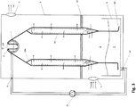
- Fig. 3 shows another embodiment.
- the exchange element 11 is tubular at least in the exchange region below the reservoir 7.
- a supporting element 14 is arranged inside the tubular exchange element 11 in order to support the separation of the walls of the exchange element.
- the supporting element 14 can be a perforated tube.
- a perforated plate 15 is arranged at a lower end of the duct 3.
- the exchange element 11 is positioned such that the lower end of the exchange element fits through an opening of the perforated plate 15.
- Gas 1 provided by the gas inlet 4 flows through the lower part of the exchange element 11 and then further inside the supporting element 14 along the exchange region, being in direct contact with the liquid here.
- the gas may leave the tubular exchange element 11 through openings in the supporting element 14 and through the permeable structure of the exchange element 11.
- a pump 12 is connected to the liquid inlet 6.
- the liquid outlet 10 is connected with the liquid inlet 6 providing a liquid circuit.
Landscapes
- Engineering & Computer Science (AREA)
- Mechanical Engineering (AREA)
- General Engineering & Computer Science (AREA)
- Physics & Mathematics (AREA)
- Thermal Sciences (AREA)
- Heat-Exchange Devices With Radiators And Conduit Assemblies (AREA)
- Physical Or Chemical Processes And Apparatus (AREA)
Abstract
Description
- The invention relates to a device for heat transfer between a liquid and a gas and a method for operating the device.
- By providing a direct contact exchange surface between gas and a liquid aiming at heat and / or mass transfer, several problems usually appear, mainly:
- Unequal distribution of the liquid on a given surface structure: Parts of the provided surface are not wetted by the liquid and, hereby, the surface structure remains partially inefficient.
- Distribution systems, like perforated tubes or containers, spray nozzles or rotating arm distributors aim at providing an even distribution of the liquid on the surface structure, but are not working in sufficient precision, or are limited to a specific range of liquid mass flow. Especially at very small liquid volume flow rate ranges, most of the distribution systems fail.
- Within gas to liquid direct contact heat exchangers, drops usually appear on the way between a liquid distribution device to the contact surface, within the contact surface and on the way from the contact surface to a liquid re-collector. In some cases, like under use of demineralized water as liquid, this is a positive effect, as water droplets are providing an increased surface between gas and liquid in addition to the provided contact surface. However, using liquid desiccants such as salt solutions, ionic liquids or alike, the formation of droplets may be captured by the gas stream going through the device. In this way, parts of the desiccant are taken out of the system and may cause corrosion problems in the following pathway of the gas. Furthermore, the outtake is reducing the desiccant content within the system, causing the need of regular desiccant refill.
-
Document DE 10 2009 000 617 A1 discloses a liquid distributor with different pathways, that are dividing the volume flows of the liquid into several portions, that allow a well distributed flow from the distributor to a wet pad, like a textile surface automatically. This is achieved by providing a number of primary distribution chambers, which are used for lower volume flows and an overflow within these chambers, distributing additional amount of the liquid to additional openings in the distributor between the first type openings, thus equally distributing the total flow at different volume flows. Distributing liquids over a large surface requires several intermediate distributors to renew an equal flow over the surface. - It is an object to provide improve techniques for heat transfer between a liquid and a gas.
- In one aspect, a device for heat transfer between a liquid and a gas according to
claim 1 is provided. In another aspect, a method for operating the device according to claim 13 is provided. Further embodiments are subject matter of dependent claims. - In one aspect, a device for heat transfer between a liquid and a gas is provided. The device comprises a gas inlet for providing the gas into an exchange region, a gas outlet for retrieving the gas from the exchange region, a liquid inlet connected to a reservoir for holding the liquid, wherein the reservoir is formed with an opening in an upper part of the reservoir, and wherein the reservoir is arranged at an upper end of the exchange region, an impounding basin, wherein the impounding basin is arranged below the reservoir, and wherein the impounding basin is formed with a liquid outlet, and an exchange element arranged in the exchange region. An upper part of the exchange element is disposed through the opening of the reservoir such that the upper part of the exchange element is arranged at least partially inside the reservoir and such that the upper part of the exchange element is at least partially submerged in the liquid.
- In another aspect, a method for operating the device is provided. The method comprises the steps of disposing an upper part of the exchange element through the opening of the reservoir such that the upper part of the exchange element is arranged at least partially inside the reservoir, filling the reservoir at least partially with the liquid such that the upper part of the exchange elements is at least partially submerged in the liquid and a flow of liquid along the exchange element is created, providing, by the gas inlet, the gas into the exchange region, such that the gas is in direct contact with the liquid in the exchange element, and retrieving, by the gas outlet, the gas from the exchange region.
- In operation of the device, the amount of liquid flowing down the exchange element can be controlled by the size of the upper part of the exchange which is disposed inside the reservoir and by the amount of liquid being in the reservoir (the fill level of the reservoir). Obviously, if the exchange element is not in contact with the liquid, the liquid cannot flow along the exchange element. The liquid can be brought in contact with the exchange element by disposing a larger part of the exchange element inside the reservoir such that the exchange element is arranged deeper in the reservoir. Alternatively, the fill level of the reservoir with the liquid can be increased. When the liquid contacts the exchange element, at least part of the liquid starts to flow upwards the upper part of the exchange element by a capillary force (against the force of gravity). The strength of the capillary force can be controlled by the size of the exchange element being submerged in the liquid. Thus, increasing the fill level of the reservoir (between the level of first contact and the opening of the reservoir) leads to an increase of the capillary force. A higher level of liquid means a shorter distance against gravity, resulting in a higher liquid volume flow. The flow of the liquid along the exchange element can be controlled by the fill level of the reservoir. If the fill level reaches the opening of the reservoir, the liquid overflows the reservoir and is pulled by gravitation down the exchange element such that maximum volume flow is reached. The exchange element may be at least partially arranged below the reservoir.
- The reservoir can also be called a liquid distribution element. The opening can be formed in an upper half of the reservoir. In one embodiment, the opening may be formed at the top of the reservoir.
- Heat is exchanged between the liquid in the exchange element and the gas flowing along the soaked exchange element, wherein the gas is in direct contact with the liquid. In addition, mass can be exchanged between the liquid and the gas.
- The liquid can be water, a salt solution or an ionic liquid. The gas can be air, natural gas, or ammonia.
- In one embodiment, moisture is transferred from the gas to the liquid. Hereby, the liquid is heated and the moisture content of the gas is reduced. The heated liquid can be collected for further use. For example, the device can be used for drying natural gas.
- By controlling the fill level in the reservoir, the liquid can be evenly distributed along the exchange element, in vertical and / or horizontal direction. The liquid is distributed in horizontal direction of the exchange element by suction of the material of the exchange element.
- The device may comprise a duct which can surround the exchange region, the reservoir and / or the impounding basin. The gas inlet can be arranged in a lower portion of the device. The gas outlet can be arranged in an upper portion of the device.
- A lower part of the exchange element may be arranged at least partially inside the impounding basin. In this embodiment, the liquid flows along the exchange element until it reaches the impounding basin. Formation of droplets is avoided. The lower part of the exchange element may be at least partially submerged in the liquid collected in the impounding basin.
- In one embodiment, the exchange element may be tubular. A supporting element may be arranged inside the tubular exchange element. The supporting element may be a tube, a spiral or a packing material. The supporting element may be formed with a perforated surface. The exchange element can be formed as a permeable duct.
- A heat exchanger element may be arranged inside the tubular exchange element. The heat exchanger element can transport a heat transfer fluid, wherein the temperature of the heat transfer fluid is different from the temperature of the liquid. The heat exchanger element can be connected to a heating or cooling cycle, forming a heat exchanger unit. Walls of the heat exchanger element can be in direct contact with the liquid flowing along the exchange element. The heat exchanger element can be formed as a tube or a spiral. The heat exchanger element may be made from a plastic material. The heat exchanger element can also provide support to the exchange element. In this case, the heat exchanger element and the supporting element are formed by a single component.
- A lower end of the tubular exchange element may be connected to a perforated plate, and the gas inlet may be configured to provide a flow of gas through the perforated plate inside the tubular exchange element. The perforated plate can be arranged above the gas inlet. The gas can flow through openings in the perforated plate inside the tubular exchange element and / or inside the supporting element. After passing through the exchange element, the gas can be removed from the device by the gas outlet.
- In another embodiment, the exchange element may be flat. The exchange element may be formed with two or more layers. A separation element may be arranged in the exchange region, wherein the layers of the exchange element are separated in the exchange region by the separation element. The two layers of the exchange element may be arranged parallel to each other in the exchange region by the separation element. The two layers of the exchange element may be in direct contact with each other within the reservoir. The supporting element may be formed by stabs or tensed ropes. The heat exchanger element can be exposed to the flat exchange element. In one embodiment, the heat exchanger tube may be disposed between two layers of the exchange material or within the layers of the exchange element (if the exchange element comprises three or more layers).
- The exchange element may be made of an absorbent material, for example a textile, e.g. cotton fabric.
- Several exchange elements can be arranged in the exchange region, wherein an upper part of each exchange element is disposed at least partly in the reservoir.
- The liquid can be moved to the liquid inlet by at least one of the following methods. A liquid pump can be connected to the liquid inlet. The flow of the liquid can be controlled by controlling the operational speed of the liquid pump. Alternatively or in addition, a liquid source can be arranged above the liquid inlet and the pressure of liquid at the liquid inlet and the related mass flow of the liquid are at least partially controlled by controlling the opening level of the liquid inlet, e.g. using a throttle valve.
- The gas can be moved through from the gas inlet through the exchange region to the gas outlet using a ventilator and / or using natural convection, e.g. due to differences of gas density between in- and outgoing gas caused by heat transfer between liquid and gas within the exchange region.
- The features disclosed in reference to the device also apply to the method for operating the device and vice versa.
- In the following, embodiments are described with reference to figures of a drawing.
-
Fig. 1 shows a first embodiment of a device for heat transfer between a liquid and a gas. -
Fig. 2 shows a second embodiment of a device for heat transfer between a liquid and a gas. -
Fig. 3 shows a third embodiment of a device for heat transfer between a liquid and a gas. - In the following, same reference numbers are used for same components.
-
Fig. 1 shows a first embodiment of a heat (and mass) transfer device. The device comprises aduct 3. Thereservoir 7, the exchange element 11 and the impoundingbasin 9 are arranged within theduct 3. Agas inlet 4 is formed in a lower region of theduct 3. Agas outlet 5 is formed at an upper region of theduct 3. A gas stream flows from thegas inlet 4 to thegas outlet 5. - In an upper part of the device, a
reservoir 7 is arranged which is in connection to aliquid inlet 6. Aliquid impounding basin 9 is arranged below thereservoir 7. An exchange element 11 (also called wet pad) is arranged between thereservoir 7 and the impoundingbasin 9. Anupper part 11a of the exchange element is disposed through anopening 20 of thereservoir 7 such that theupper part 11a is arranged inside thereservoir 7. Theupper part 11a may touch a bottom of the reservoir.Liquid 2 is filled in the reservoir via theliquid inlet 6. When the liquid 2 contacts theupper part 11a of the exchange element 11, capillary forces draw the liquid along the exchange element (against the force of gravity). By controlling the fill level of the reservoir, the strength of the capillary forces is determined. Liquid flows along theupper part 11a of the exchange element 11 until it reaches theopening 20. Theopening 20 provides an overflow 8. After the liquid 2 passes the opening 20 (and overflow 8), it is drawn by gravitation downwards the exchange element 11. Theliquid 2 is gathered in the impoundingbasin 9 which is formed with aliquid outlet 10 for retrieving theliquid 2. Alower part 11c of the exchange element 11 is arranged in the impoundingbasin 9. Hereby, formation of droplets is avoided. - A stream of gas is provided by a
gas inlet 4. The gas streams along the exchange elements where it is in direct contact with the liquid. Heat (and mass) can be exchanged between the gas and the liquid. The gas is retrieved from the device by agas outlet 5. - Another embodiment of the device is shown in
Fig. 2 . Several exchange elements are arranged in the exchange region. Further, aseparation element 16 is provided. The exchange elements 11 are each formed by two layers of a material (e.g. a textile). The two layers are put together in the upper part of the exchange elements. Inside the exchange region, the two layers are separated by theseparation element 16 such that the two layers of each exchange element 11ba, 11bb hang parallel to each other. -
Fig. 3 shows another embodiment. The exchange element 11 is tubular at least in the exchange region below thereservoir 7. A supportingelement 14 is arranged inside the tubular exchange element 11 in order to support the separation of the walls of the exchange element. The supportingelement 14 can be a perforated tube. At a lower end of theduct 3, aperforated plate 15 is arranged. The exchange element 11 is positioned such that the lower end of the exchange element fits through an opening of theperforated plate 15.Gas 1 provided by thegas inlet 4 flows through the lower part of the exchange element 11 and then further inside the supportingelement 14 along the exchange region, being in direct contact with the liquid here. The gas may leave the tubular exchange element 11 through openings in the supportingelement 14 and through the permeable structure of the exchange element 11. - A
pump 12 is connected to theliquid inlet 6. Hereby, the amount of liquid transported to thereservoir 7 can be controlled. Theliquid outlet 10 is connected with theliquid inlet 6 providing a liquid circuit. - The features disclosed in the specification, the claims and the figures can be relevant for implementing embodiments, either alone or in any possible combination of each other.
Claims (15)
- A device for heat transfer between a liquid and a gas, comprising:- a gas inlet for providing the gas into an exchange region,- a gas outlet for retrieving the gas from the exchange region,- a liquid inlet connected to a reservoir for holding the liquid, wherein the reservoir is formed with an opening in an upper region of the reservoir, and wherein the reservoir is arranged at an upper end of the exchange region,- an impounding basin, wherein the impounding basin is arranged below the reservoir, and wherein the impounding basin is formed with a liquid outlet, and- an exchange element arranged in the exchange region,
wherein an upper part of the exchange element is disposed through the opening of the reservoir such that the upper part of the exchange element is arranged at least partially inside the reservoir and such that the upper part of the exchange element is at least partially submerged in the liquid. - The device of claim 1, wherein a lower part of the exchange element is arranged at least partially inside the impounding basin.
- The device of claim 1 or 2, wherein the exchange element is tubular.
- The device of claim 3, wherein a supporting element is arranged inside the tubular exchange element.
- The device of claim 4, wherein the supporting element is a tube.
- The device of claim 4 or 5, wherein the supporting element is formed with a perforated surface.
- The device of claim 4, wherein the supporting element is a spiral.
- The device of one of the claims 3 to 7, wherein a heat exchanger element is arranged inside the tubular exchange element.
- The device of one of the claims 3 to 8, wherein a lower end of the tubular exchange element is connected to a perforated plate, and wherein the gas inlet is configured to provide a flow of gas through the perforated plate inside the tubular exchange element.
- The device of claim 1 or 2, wherein the exchange element is flat.
- The device of one of the claims 1, 2 or 10, wherein the exchange element is formed with two layers, wherein a separation element is arranged in the exchange region, and wherein the two layers of the exchange element are separated in the exchange region by the separation element.
- The device of claim 11, wherein the two layers of the exchange element are arranged parallel to each other in the exchange region by the separation element.
- The device of one of the claims 10 to 12, wherein a heat exchanger element is exposed to the flat exchange element.
- The device of one of the preceding claims, wherein the exchange element is made of an absorbent material.
- A method for operating a heat transfer device, wherein the heat transfer device comprises:- a gas inlet,- a gas outlet,- a liquid inlet connected to a reservoir for holding the liquid, wherein the reservoir is formed with an opening in an upper region of the reservoir, and wherein the reservoir is arranged at an upper end of the exchange region,- an impounding basin, wherein the impounding basin is arranged below the reservoir, and wherein the impounding basin is formed with a liquid outlet, and- an exchange element arranged in the exchange region,
and wherein the method comprises steps of:- disposing an upper part of the exchange element through the opening of the reservoir such that the upper part of the exchange element is arranged at least partially inside the reservoir,- filling the reservoir at least partially with the liquid such that the upper part of the exchange element is at least partially submerged in the liquid and a flow of liquid along the exchange element is created,- providing, by the gas inlet, the gas into the exchange region, such that the gas is in direct contact with the liquid in the exchange element, and- retrieving, by the gas outlet, the gas from the exchange region.
Priority Applications (3)
| Application Number | Priority Date | Filing Date | Title |
|---|---|---|---|
| EP14198449.2A EP3034980B1 (en) | 2014-12-17 | 2014-12-17 | Device for heat transfer between a liquid and a gas and method for operating the device |
| US15/536,990 US20180003442A1 (en) | 2014-12-17 | 2015-12-17 | Device for heat transfer between a liquid and a gas and method for operating the device |
| PCT/EP2015/080202 WO2016097132A1 (en) | 2014-12-17 | 2015-12-17 | Device for heat transfer between a liquid and a gas and method for operating the device |
Applications Claiming Priority (1)
| Application Number | Priority Date | Filing Date | Title |
|---|---|---|---|
| EP14198449.2A EP3034980B1 (en) | 2014-12-17 | 2014-12-17 | Device for heat transfer between a liquid and a gas and method for operating the device |
Publications (2)
| Publication Number | Publication Date |
|---|---|
| EP3034980A1 true EP3034980A1 (en) | 2016-06-22 |
| EP3034980B1 EP3034980B1 (en) | 2017-07-12 |
Family
ID=52278366
Family Applications (1)
| Application Number | Title | Priority Date | Filing Date |
|---|---|---|---|
| EP14198449.2A Active EP3034980B1 (en) | 2014-12-17 | 2014-12-17 | Device for heat transfer between a liquid and a gas and method for operating the device |
Country Status (3)
| Country | Link |
|---|---|
| US (1) | US20180003442A1 (en) |
| EP (1) | EP3034980B1 (en) |
| WO (1) | WO2016097132A1 (en) |
Citations (8)
| Publication number | Priority date | Publication date | Assignee | Title |
|---|---|---|---|---|
| GB498715A (en) * | 1936-12-18 | 1939-01-12 | Rene Velut | Improvements in and relating to liquid cooling devices |
| FR2491773A1 (en) * | 1980-10-15 | 1982-04-16 | Caso Pillet Sarl | Physical and or chemical exchange between liq. and gas - with gas rising through perforated bed plate into supported liq. |
| FR2691372A1 (en) * | 1992-05-22 | 1993-11-26 | Aerospatiale | Heating aq. liquid effluents - by evaporating off the liquid and recovering the solutes in crystalline form |
| US5783119A (en) * | 1994-09-28 | 1998-07-21 | Sulzer Chemtech Ag | Liquid distributor for columns |
| EP1013324A2 (en) * | 1998-11-30 | 2000-06-28 | Sulzer Chemtech AG | Counter-current column with liquid distributor |
| EP1459793A1 (en) * | 2003-03-17 | 2004-09-22 | Sulzer Chemtech AG | Liquid distributor |
| DE102009000617A1 (en) | 2009-02-04 | 2010-08-05 | Universität Kassel | Device for dehumidifying, heating and / or cooling a fluid |
| WO2013139756A1 (en) * | 2012-03-19 | 2013-09-26 | Alstom Technology Ltd | Direct contact condenser |
Family Cites Families (4)
| Publication number | Priority date | Publication date | Assignee | Title |
|---|---|---|---|---|
| US3284068A (en) * | 1964-02-26 | 1966-11-08 | Mc Graw Edison Co | Flow adjustable water trough means for evaporative cooler pads |
| US3290025A (en) * | 1965-11-19 | 1966-12-06 | Baltimore Aircoil Co Inc | Trough system for evaporative heat exchangers |
| CH671165A5 (en) * | 1987-03-02 | 1989-08-15 | Sulzer Ag | |
| EP1464370A1 (en) * | 2003-03-17 | 2004-10-06 | Sulzer Chemtech AG | Liquid distributor |
-
2014
- 2014-12-17 EP EP14198449.2A patent/EP3034980B1/en active Active
-
2015
- 2015-12-17 US US15/536,990 patent/US20180003442A1/en not_active Abandoned
- 2015-12-17 WO PCT/EP2015/080202 patent/WO2016097132A1/en not_active Ceased
Patent Citations (8)
| Publication number | Priority date | Publication date | Assignee | Title |
|---|---|---|---|---|
| GB498715A (en) * | 1936-12-18 | 1939-01-12 | Rene Velut | Improvements in and relating to liquid cooling devices |
| FR2491773A1 (en) * | 1980-10-15 | 1982-04-16 | Caso Pillet Sarl | Physical and or chemical exchange between liq. and gas - with gas rising through perforated bed plate into supported liq. |
| FR2691372A1 (en) * | 1992-05-22 | 1993-11-26 | Aerospatiale | Heating aq. liquid effluents - by evaporating off the liquid and recovering the solutes in crystalline form |
| US5783119A (en) * | 1994-09-28 | 1998-07-21 | Sulzer Chemtech Ag | Liquid distributor for columns |
| EP1013324A2 (en) * | 1998-11-30 | 2000-06-28 | Sulzer Chemtech AG | Counter-current column with liquid distributor |
| EP1459793A1 (en) * | 2003-03-17 | 2004-09-22 | Sulzer Chemtech AG | Liquid distributor |
| DE102009000617A1 (en) | 2009-02-04 | 2010-08-05 | Universität Kassel | Device for dehumidifying, heating and / or cooling a fluid |
| WO2013139756A1 (en) * | 2012-03-19 | 2013-09-26 | Alstom Technology Ltd | Direct contact condenser |
Also Published As
| Publication number | Publication date |
|---|---|
| US20180003442A1 (en) | 2018-01-04 |
| EP3034980B1 (en) | 2017-07-12 |
| WO2016097132A1 (en) | 2016-06-23 |
Similar Documents
| Publication | Publication Date | Title |
|---|---|---|
| CN103796723B (en) | Apparatus and method for bringing a gas into contact with a liquid | |
| CN108225095B (en) | Cooling tower water distribution system | |
| US9993743B2 (en) | Distributor tray for gas/liquid contact column with secondary distribution system | |
| RU2015152497A (en) | Multistage bubble column humidifier | |
| JP6855765B2 (en) | Gas-liquid contact device | |
| CN102954628A (en) | Liquid distributor for film falling type evaporator | |
| JP2017190928A (en) | Treatment machine and regeneration machine | |
| JP6789946B2 (en) | Evaporator, evaporation method and sealing system | |
| EP3135365A2 (en) | Device for extracting water from the environment | |
| BR112019021074B1 (en) | DUAL LIQUID DISTRIBUTION DEVICE, VESSEL OR FLOATING SUPPORT AND METHOD FOR DISTRIBUTING LIQUID USING A DUAL LIQUID DISTRIBUTION DEVICE | |
| US11236932B2 (en) | Evaporator and a method for vaporizing a substance in an evaporator | |
| BR112012032752B1 (en) | method of operating a contact column section | |
| EP3034980B1 (en) | Device for heat transfer between a liquid and a gas and method for operating the device | |
| CN208525859U (en) | A kind of high efficiency packing rectifying column being convenient for changing | |
| CN105879586A (en) | Absorption tower with absorption separator | |
| CN106492741B (en) | A kind of tower tray for sieve-plate tower | |
| CN204723990U (en) | A kind of packed tower of uniform liquid distribution | |
| CN103851738B (en) | A kind of fresh-keeping humidifier | |
| JP6990099B2 (en) | Carbon dioxide capture system and its operation method | |
| SE428723B (en) | SUPPLY FOR ABSORBATORS, FOR ABSORPTION COOLERS WITH AT LEAST TWO ABSORBATORS | |
| CN208553184U (en) | Packed tower barrel structure and stuffing rectification column | |
| RU2280817C2 (en) | Indirect evaporation air cooling plant | |
| JP6602576B2 (en) | Gas condensing device with reflux separator | |
| JP2009160529A (en) | Degassing method and degassing device for coating liquid | |
| Stephani | Experimental study on the feasibility of falling film absorbers for dehumidification in cold stores |
Legal Events
| Date | Code | Title | Description |
|---|---|---|---|
| PUAI | Public reference made under article 153(3) epc to a published international application that has entered the european phase |
Free format text: ORIGINAL CODE: 0009012 |
|
| 17P | Request for examination filed |
Effective date: 20141217 |
|
| AK | Designated contracting states |
Kind code of ref document: A1 Designated state(s): AL AT BE BG CH CY CZ DE DK EE ES FI FR GB GR HR HU IE IS IT LI LT LU LV MC MK MT NL NO PL PT RO RS SE SI SK SM TR |
|
| AX | Request for extension of the european patent |
Extension state: BA ME |
|
| RBV | Designated contracting states (corrected) |
Designated state(s): AL AT BE BG CH CY CZ DE DK EE ES FI FR GB GR HR HU IE IS IT LI LT LU LV MC MK MT NL NO PL PT RO RS SE SI SK SM TR |
|
| GRAP | Despatch of communication of intention to grant a patent |
Free format text: ORIGINAL CODE: EPIDOSNIGR1 |
|
| RIC1 | Information provided on ipc code assigned before grant |
Ipc: F28C 3/06 20060101ALI20170113BHEP Ipc: F28F 25/02 20060101AFI20170113BHEP |
|
| INTG | Intention to grant announced |
Effective date: 20170206 |
|
| GRAS | Grant fee paid |
Free format text: ORIGINAL CODE: EPIDOSNIGR3 |
|
| GRAA | (expected) grant |
Free format text: ORIGINAL CODE: 0009210 |
|
| AK | Designated contracting states |
Kind code of ref document: B1 Designated state(s): AL AT BE BG CH CY CZ DE DK EE ES FI FR GB GR HR HU IE IS IT LI LT LU LV MC MK MT NL NO PL PT RO RS SE SI SK SM TR |
|
| REG | Reference to a national code |
Ref country code: GB Ref legal event code: FG4D |
|
| REG | Reference to a national code |
Ref country code: CH Ref legal event code: EP |
|
| REG | Reference to a national code |
Ref country code: AT Ref legal event code: REF Ref document number: 908753 Country of ref document: AT Kind code of ref document: T Effective date: 20170715 |
|
| REG | Reference to a national code |
Ref country code: IE Ref legal event code: FG4D |
|
| REG | Reference to a national code |
Ref country code: DE Ref legal event code: R096 Ref document number: 602014011690 Country of ref document: DE |
|
| REG | Reference to a national code |
Ref country code: NL Ref legal event code: MP Effective date: 20170712 |
|
| REG | Reference to a national code |
Ref country code: LT Ref legal event code: MG4D |
|
| REG | Reference to a national code |
Ref country code: FR Ref legal event code: PLFP Year of fee payment: 4 |
|
| PG25 | Lapsed in a contracting state [announced via postgrant information from national office to epo] |
Ref country code: SE Free format text: LAPSE BECAUSE OF FAILURE TO SUBMIT A TRANSLATION OF THE DESCRIPTION OR TO PAY THE FEE WITHIN THE PRESCRIBED TIME-LIMIT Effective date: 20170712 Ref country code: NL Free format text: LAPSE BECAUSE OF FAILURE TO SUBMIT A TRANSLATION OF THE DESCRIPTION OR TO PAY THE FEE WITHIN THE PRESCRIBED TIME-LIMIT Effective date: 20170712 Ref country code: NO Free format text: LAPSE BECAUSE OF FAILURE TO SUBMIT A TRANSLATION OF THE DESCRIPTION OR TO PAY THE FEE WITHIN THE PRESCRIBED TIME-LIMIT Effective date: 20171012 Ref country code: FI Free format text: LAPSE BECAUSE OF FAILURE TO SUBMIT A TRANSLATION OF THE DESCRIPTION OR TO PAY THE FEE WITHIN THE PRESCRIBED TIME-LIMIT Effective date: 20170712 Ref country code: LT Free format text: LAPSE BECAUSE OF FAILURE TO SUBMIT A TRANSLATION OF THE DESCRIPTION OR TO PAY THE FEE WITHIN THE PRESCRIBED TIME-LIMIT Effective date: 20170712 Ref country code: HR Free format text: LAPSE BECAUSE OF FAILURE TO SUBMIT A TRANSLATION OF THE DESCRIPTION OR TO PAY THE FEE WITHIN THE PRESCRIBED TIME-LIMIT Effective date: 20170712 |
|
| PG25 | Lapsed in a contracting state [announced via postgrant information from national office to epo] |
Ref country code: GR Free format text: LAPSE BECAUSE OF FAILURE TO SUBMIT A TRANSLATION OF THE DESCRIPTION OR TO PAY THE FEE WITHIN THE PRESCRIBED TIME-LIMIT Effective date: 20171013 Ref country code: LV Free format text: LAPSE BECAUSE OF FAILURE TO SUBMIT A TRANSLATION OF THE DESCRIPTION OR TO PAY THE FEE WITHIN THE PRESCRIBED TIME-LIMIT Effective date: 20170712 Ref country code: RS Free format text: LAPSE BECAUSE OF FAILURE TO SUBMIT A TRANSLATION OF THE DESCRIPTION OR TO PAY THE FEE WITHIN THE PRESCRIBED TIME-LIMIT Effective date: 20170712 Ref country code: PL Free format text: LAPSE BECAUSE OF FAILURE TO SUBMIT A TRANSLATION OF THE DESCRIPTION OR TO PAY THE FEE WITHIN THE PRESCRIBED TIME-LIMIT Effective date: 20170712 Ref country code: IS Free format text: LAPSE BECAUSE OF FAILURE TO SUBMIT A TRANSLATION OF THE DESCRIPTION OR TO PAY THE FEE WITHIN THE PRESCRIBED TIME-LIMIT Effective date: 20171112 Ref country code: BG Free format text: LAPSE BECAUSE OF FAILURE TO SUBMIT A TRANSLATION OF THE DESCRIPTION OR TO PAY THE FEE WITHIN THE PRESCRIBED TIME-LIMIT Effective date: 20171012 |
|
| REG | Reference to a national code |
Ref country code: DE Ref legal event code: R097 Ref document number: 602014011690 Country of ref document: DE |
|
| PG25 | Lapsed in a contracting state [announced via postgrant information from national office to epo] |
Ref country code: DK Free format text: LAPSE BECAUSE OF FAILURE TO SUBMIT A TRANSLATION OF THE DESCRIPTION OR TO PAY THE FEE WITHIN THE PRESCRIBED TIME-LIMIT Effective date: 20170712 Ref country code: RO Free format text: LAPSE BECAUSE OF FAILURE TO SUBMIT A TRANSLATION OF THE DESCRIPTION OR TO PAY THE FEE WITHIN THE PRESCRIBED TIME-LIMIT Effective date: 20170712 Ref country code: CZ Free format text: LAPSE BECAUSE OF FAILURE TO SUBMIT A TRANSLATION OF THE DESCRIPTION OR TO PAY THE FEE WITHIN THE PRESCRIBED TIME-LIMIT Effective date: 20170712 |
|
| PGFP | Annual fee paid to national office [announced via postgrant information from national office to epo] |
Ref country code: ES Payment date: 20180102 Year of fee payment: 4 |
|
| PLBE | No opposition filed within time limit |
Free format text: ORIGINAL CODE: 0009261 |
|
| STAA | Information on the status of an ep patent application or granted ep patent |
Free format text: STATUS: NO OPPOSITION FILED WITHIN TIME LIMIT |
|
| PG25 | Lapsed in a contracting state [announced via postgrant information from national office to epo] |
Ref country code: SK Free format text: LAPSE BECAUSE OF FAILURE TO SUBMIT A TRANSLATION OF THE DESCRIPTION OR TO PAY THE FEE WITHIN THE PRESCRIBED TIME-LIMIT Effective date: 20170712 Ref country code: SM Free format text: LAPSE BECAUSE OF FAILURE TO SUBMIT A TRANSLATION OF THE DESCRIPTION OR TO PAY THE FEE WITHIN THE PRESCRIBED TIME-LIMIT Effective date: 20170712 Ref country code: IT Free format text: LAPSE BECAUSE OF FAILURE TO SUBMIT A TRANSLATION OF THE DESCRIPTION OR TO PAY THE FEE WITHIN THE PRESCRIBED TIME-LIMIT Effective date: 20170712 Ref country code: EE Free format text: LAPSE BECAUSE OF FAILURE TO SUBMIT A TRANSLATION OF THE DESCRIPTION OR TO PAY THE FEE WITHIN THE PRESCRIBED TIME-LIMIT Effective date: 20170712 |
|
| 26N | No opposition filed |
Effective date: 20180413 |
|
| PG25 | Lapsed in a contracting state [announced via postgrant information from national office to epo] |
Ref country code: ES Free format text: THE PATENT HAS BEEN ANNULLED BY A DECISION OF A NATIONAL AUTHORITY Effective date: 20170712 |
|
| PG25 | Lapsed in a contracting state [announced via postgrant information from national office to epo] |
Ref country code: IT Free format text: LAPSE BECAUSE OF FAILURE TO SUBMIT A TRANSLATION OF THE DESCRIPTION OR TO PAY THE FEE WITHIN THE PRESCRIBED TIME-LIMIT Effective date: 20170712 Ref country code: SI Free format text: LAPSE BECAUSE OF FAILURE TO SUBMIT A TRANSLATION OF THE DESCRIPTION OR TO PAY THE FEE WITHIN THE PRESCRIBED TIME-LIMIT Effective date: 20170712 |
|
| PGRI | Patent reinstated in contracting state [announced from national office to epo] |
Ref country code: IT Effective date: 20180627 |
|
| REG | Reference to a national code |
Ref country code: IE Ref legal event code: MM4A |
|
| PG25 | Lapsed in a contracting state [announced via postgrant information from national office to epo] |
Ref country code: MT Free format text: LAPSE BECAUSE OF NON-PAYMENT OF DUE FEES Effective date: 20171217 Ref country code: LU Free format text: LAPSE BECAUSE OF NON-PAYMENT OF DUE FEES Effective date: 20171217 |
|
| REG | Reference to a national code |
Ref country code: BE Ref legal event code: MM Effective date: 20171231 |
|
| PG25 | Lapsed in a contracting state [announced via postgrant information from national office to epo] |
Ref country code: IE Free format text: LAPSE BECAUSE OF NON-PAYMENT OF DUE FEES Effective date: 20171217 |
|
| PG25 | Lapsed in a contracting state [announced via postgrant information from national office to epo] |
Ref country code: BE Free format text: LAPSE BECAUSE OF NON-PAYMENT OF DUE FEES Effective date: 20171231 |
|
| PG25 | Lapsed in a contracting state [announced via postgrant information from national office to epo] |
Ref country code: HU Free format text: LAPSE BECAUSE OF FAILURE TO SUBMIT A TRANSLATION OF THE DESCRIPTION OR TO PAY THE FEE WITHIN THE PRESCRIBED TIME-LIMIT; INVALID AB INITIO Effective date: 20141217 Ref country code: MC Free format text: LAPSE BECAUSE OF FAILURE TO SUBMIT A TRANSLATION OF THE DESCRIPTION OR TO PAY THE FEE WITHIN THE PRESCRIBED TIME-LIMIT Effective date: 20170712 |
|
| PG25 | Lapsed in a contracting state [announced via postgrant information from national office to epo] |
Ref country code: CY Free format text: LAPSE BECAUSE OF FAILURE TO SUBMIT A TRANSLATION OF THE DESCRIPTION OR TO PAY THE FEE WITHIN THE PRESCRIBED TIME-LIMIT Effective date: 20170712 |
|
| PG25 | Lapsed in a contracting state [announced via postgrant information from national office to epo] |
Ref country code: MK Free format text: LAPSE BECAUSE OF FAILURE TO SUBMIT A TRANSLATION OF THE DESCRIPTION OR TO PAY THE FEE WITHIN THE PRESCRIBED TIME-LIMIT Effective date: 20170712 |
|
| PG25 | Lapsed in a contracting state [announced via postgrant information from national office to epo] |
Ref country code: TR Free format text: LAPSE BECAUSE OF FAILURE TO SUBMIT A TRANSLATION OF THE DESCRIPTION OR TO PAY THE FEE WITHIN THE PRESCRIBED TIME-LIMIT Effective date: 20170712 |
|
| PG25 | Lapsed in a contracting state [announced via postgrant information from national office to epo] |
Ref country code: PT Free format text: LAPSE BECAUSE OF FAILURE TO SUBMIT A TRANSLATION OF THE DESCRIPTION OR TO PAY THE FEE WITHIN THE PRESCRIBED TIME-LIMIT Effective date: 20170712 |
|
| PG25 | Lapsed in a contracting state [announced via postgrant information from national office to epo] |
Ref country code: AL Free format text: LAPSE BECAUSE OF FAILURE TO SUBMIT A TRANSLATION OF THE DESCRIPTION OR TO PAY THE FEE WITHIN THE PRESCRIBED TIME-LIMIT Effective date: 20170712 |
|
| REG | Reference to a national code |
Ref country code: CH Ref legal event code: PUE Owner name: WATERGY GMBH, DE Free format text: FORMER OWNER: TECHNISCHE UNIVERSITAET BERLIN, DE |
|
| REG | Reference to a national code |
Ref country code: AT Ref legal event code: MM01 Ref document number: 908753 Country of ref document: AT Kind code of ref document: T Effective date: 20191217 |
|
| REG | Reference to a national code |
Ref country code: DE Ref legal event code: R081 Ref document number: 602014011690 Country of ref document: DE Owner name: WATERGY GMBH, DE Free format text: FORMER OWNER: TECHNISCHE UNIVERSITAET BERLIN, 10623 BERLIN, DE |
|
| PG25 | Lapsed in a contracting state [announced via postgrant information from national office to epo] |
Ref country code: AT Free format text: LAPSE BECAUSE OF NON-PAYMENT OF DUE FEES Effective date: 20191217 |
|
| REG | Reference to a national code |
Ref country code: DE Ref legal event code: R409 Ref document number: 602014011690 Country of ref document: DE Ref country code: DE Ref legal event code: R119 Ref document number: 602014011690 Country of ref document: DE |
|
| PGFP | Annual fee paid to national office [announced via postgrant information from national office to epo] |
Ref country code: GB Payment date: 20221223 Year of fee payment: 9 |
|
| REG | Reference to a national code |
Ref country code: AT Ref legal event code: UEP Ref document number: 908753 Country of ref document: AT Kind code of ref document: T Effective date: 20170712 |
|
| PGFP | Annual fee paid to national office [announced via postgrant information from national office to epo] |
Ref country code: CH Payment date: 20240304 Year of fee payment: 10 |
|
| PGFP | Annual fee paid to national office [announced via postgrant information from national office to epo] |
Ref country code: DE Payment date: 20240301 Year of fee payment: 10 |
|
| GBPC | Gb: european patent ceased through non-payment of renewal fee |
Effective date: 20231217 |
|
| PG25 | Lapsed in a contracting state [announced via postgrant information from national office to epo] |
Ref country code: GB Free format text: LAPSE BECAUSE OF NON-PAYMENT OF DUE FEES Effective date: 20231217 |
|
| PG25 | Lapsed in a contracting state [announced via postgrant information from national office to epo] |
Ref country code: GB Free format text: LAPSE BECAUSE OF NON-PAYMENT OF DUE FEES Effective date: 20231217 |
|
| REG | Reference to a national code |
Ref country code: DE Ref legal event code: R119 Ref document number: 602014011690 Country of ref document: DE |
|
| PGFP | Annual fee paid to national office [announced via postgrant information from national office to epo] |
Ref country code: FR Payment date: 20250628 Year of fee payment: 12 |
|
| REG | Reference to a national code |
Ref country code: CH Ref legal event code: PL |
|
| PG25 | Lapsed in a contracting state [announced via postgrant information from national office to epo] |
Ref country code: DE Free format text: LAPSE BECAUSE OF NON-PAYMENT OF DUE FEES Effective date: 20250701 |
|
| PGFP | Annual fee paid to national office [announced via postgrant information from national office to epo] |
Ref country code: IT Payment date: 20250630 Year of fee payment: 11 |
|
| PG25 | Lapsed in a contracting state [announced via postgrant information from national office to epo] |
Ref country code: CH Free format text: LAPSE BECAUSE OF NON-PAYMENT OF DUE FEES Effective date: 20241231 |