EP3034967A1 - Control device, control method, and program - Google Patents
Control device, control method, and program Download PDFInfo
- Publication number
- EP3034967A1 EP3034967A1 EP15199714.5A EP15199714A EP3034967A1 EP 3034967 A1 EP3034967 A1 EP 3034967A1 EP 15199714 A EP15199714 A EP 15199714A EP 3034967 A1 EP3034967 A1 EP 3034967A1
- Authority
- EP
- European Patent Office
- Prior art keywords
- power element
- temperature
- refrigerant
- heat exchanger
- cooling operation
- Prior art date
- Legal status (The legal status is an assumption and is not a legal conclusion. Google has not performed a legal analysis and makes no representation as to the accuracy of the status listed.)
- Withdrawn
Links
Images



Classifications
-
- F—MECHANICAL ENGINEERING; LIGHTING; HEATING; WEAPONS; BLASTING
- F25—REFRIGERATION OR COOLING; COMBINED HEATING AND REFRIGERATION SYSTEMS; HEAT PUMP SYSTEMS; MANUFACTURE OR STORAGE OF ICE; LIQUEFACTION SOLIDIFICATION OF GASES
- F25B—REFRIGERATION MACHINES, PLANTS OR SYSTEMS; COMBINED HEATING AND REFRIGERATION SYSTEMS; HEAT PUMP SYSTEMS
- F25B49/00—Arrangement or mounting of control or safety devices
- F25B49/02—Arrangement or mounting of control or safety devices for compression type machines, plants or systems
- F25B49/025—Motor control arrangements
-
- F—MECHANICAL ENGINEERING; LIGHTING; HEATING; WEAPONS; BLASTING
- F25—REFRIGERATION OR COOLING; COMBINED HEATING AND REFRIGERATION SYSTEMS; HEAT PUMP SYSTEMS; MANUFACTURE OR STORAGE OF ICE; LIQUEFACTION SOLIDIFICATION OF GASES
- F25B—REFRIGERATION MACHINES, PLANTS OR SYSTEMS; COMBINED HEATING AND REFRIGERATION SYSTEMS; HEAT PUMP SYSTEMS
- F25B47/00—Arrangements for preventing or removing deposits or corrosion, not provided for in another subclass
- F25B47/02—Defrosting cycles
- F25B47/022—Defrosting cycles hot gas defrosting
- F25B47/025—Defrosting cycles hot gas defrosting by reversing the cycle
-
- F—MECHANICAL ENGINEERING; LIGHTING; HEATING; WEAPONS; BLASTING
- F25—REFRIGERATION OR COOLING; COMBINED HEATING AND REFRIGERATION SYSTEMS; HEAT PUMP SYSTEMS; MANUFACTURE OR STORAGE OF ICE; LIQUEFACTION SOLIDIFICATION OF GASES
- F25B—REFRIGERATION MACHINES, PLANTS OR SYSTEMS; COMBINED HEATING AND REFRIGERATION SYSTEMS; HEAT PUMP SYSTEMS
- F25B49/00—Arrangement or mounting of control or safety devices
- F25B49/02—Arrangement or mounting of control or safety devices for compression type machines, plants or systems
-
- F—MECHANICAL ENGINEERING; LIGHTING; HEATING; WEAPONS; BLASTING
- F25—REFRIGERATION OR COOLING; COMBINED HEATING AND REFRIGERATION SYSTEMS; HEAT PUMP SYSTEMS; MANUFACTURE OR STORAGE OF ICE; LIQUEFACTION SOLIDIFICATION OF GASES
- F25B—REFRIGERATION MACHINES, PLANTS OR SYSTEMS; COMBINED HEATING AND REFRIGERATION SYSTEMS; HEAT PUMP SYSTEMS
- F25B13/00—Compression machines, plants or systems, with reversible cycle
-
- F—MECHANICAL ENGINEERING; LIGHTING; HEATING; WEAPONS; BLASTING
- F25—REFRIGERATION OR COOLING; COMBINED HEATING AND REFRIGERATION SYSTEMS; HEAT PUMP SYSTEMS; MANUFACTURE OR STORAGE OF ICE; LIQUEFACTION SOLIDIFICATION OF GASES
- F25B—REFRIGERATION MACHINES, PLANTS OR SYSTEMS; COMBINED HEATING AND REFRIGERATION SYSTEMS; HEAT PUMP SYSTEMS
- F25B2313/00—Compression machines, plants or systems with reversible cycle not otherwise provided for
- F25B2313/029—Control issues
-
- F—MECHANICAL ENGINEERING; LIGHTING; HEATING; WEAPONS; BLASTING
- F25—REFRIGERATION OR COOLING; COMBINED HEATING AND REFRIGERATION SYSTEMS; HEAT PUMP SYSTEMS; MANUFACTURE OR STORAGE OF ICE; LIQUEFACTION SOLIDIFICATION OF GASES
- F25B—REFRIGERATION MACHINES, PLANTS OR SYSTEMS; COMBINED HEATING AND REFRIGERATION SYSTEMS; HEAT PUMP SYSTEMS
- F25B2600/00—Control issues
- F25B2600/02—Compressor control
- F25B2600/021—Inverters therefor
-
- F—MECHANICAL ENGINEERING; LIGHTING; HEATING; WEAPONS; BLASTING
- F25—REFRIGERATION OR COOLING; COMBINED HEATING AND REFRIGERATION SYSTEMS; HEAT PUMP SYSTEMS; MANUFACTURE OR STORAGE OF ICE; LIQUEFACTION SOLIDIFICATION OF GASES
- F25B—REFRIGERATION MACHINES, PLANTS OR SYSTEMS; COMBINED HEATING AND REFRIGERATION SYSTEMS; HEAT PUMP SYSTEMS
- F25B31/00—Compressor arrangements
- F25B31/006—Cooling of compressor or motor
-
- Y—GENERAL TAGGING OF NEW TECHNOLOGICAL DEVELOPMENTS; GENERAL TAGGING OF CROSS-SECTIONAL TECHNOLOGIES SPANNING OVER SEVERAL SECTIONS OF THE IPC; TECHNICAL SUBJECTS COVERED BY FORMER USPC CROSS-REFERENCE ART COLLECTIONS [XRACs] AND DIGESTS
- Y02—TECHNOLOGIES OR APPLICATIONS FOR MITIGATION OR ADAPTATION AGAINST CLIMATE CHANGE
- Y02B—CLIMATE CHANGE MITIGATION TECHNOLOGIES RELATED TO BUILDINGS, e.g. HOUSING, HOUSE APPLIANCES OR RELATED END-USER APPLICATIONS
- Y02B30/00—Energy efficient heating, ventilation or air conditioning [HVAC]
- Y02B30/70—Efficient control or regulation technologies, e.g. for control of refrigerant flow, motor or heating
Definitions
- the invention relates to a control device, a control method, and a program for implementing such a method.
- a control called a defrost control for temporarily performing a cooling operation in order to prevent freezing or frosting in a heat exchanger of an outdoor unit in a heating operation is performed.
- Patent Literature 1 Japanese Unexamined Patent Application, First Publication No. 2010-025374 discloses related art.
- a device disclosed in Patent Literature 1 determines condensation in the vicinity of a power element when a cooling operation is switched to a heating operation. When the condensation occurs, the device reduces the occurrence of condensation by increasing a temperature of the power element.
- a portion that is in a high temperature state in the refrigerant circuit may temporarily enter a low temperature state.
- a power element is present at the portion, the temperature of the power element is greatly changed, and thus, the lifetime of the power element is shortened.
- An object of the invention is to provide a control device, a control method, and a program capable of solving these problems.
- a control device includes: a refrigerant circuit controller that increases a temperature of a heat exchanger in a cooling operation, the cooling operation being temporarily performed during a heating operation; and a power element controller that increases a loss of a power element in the cooling operation compared with a loss of the power element in the heating operation, the power element forming an inverter circuit that controls a compressor motor.
- the power element controller may increase a switching frequency of the inverter circuit in the cooling operation compared with a switching frequency of the inverter circuit in the heating operation.
- the power element controller may control the compressor motor in a three-phase modulation manner in the cooling operation, and the power element controller controls the compressor motor in a two-phase modulation manner in the heating operation.
- the power element controller may decrease a power factor of the inverter circuit in the cooling operation compared with a power factor of the inverter circuit in the heating operation.
- a control method includes: increasing a temperature of a heat exchanger in a cooling operation, the cooling operation being temporarily performed during a heating operation; and increasing a loss of a power element in the cooling operation compared with a loss of the power element in the heating operation, the power element forming an inverter circuit that controls a compressor motor.
- the invention also relates to a computer program product loadable directly into a memory of a computing system, comprising software code portions for the execution of the control method according to the fifth aspect of the invention when said program is executed on said computing system.
- the invention also relates to a medium readable by a computing system, having computer-executable instructions adapted for effecting the execution by the computing system of the control method according to the fifth aspect of the invention.
- a program causes a computer to execute: increasing a temperature of a heat exchanger in a cooling operation, the cooling operation being temporarily performed during a heating operation; and increasing a loss of a power element in the cooling operation compared with a loss of the power element in the heating operation, the power element forming an inverter circuit that controls a compressor motor.
- control device the control method, and the program, it is possible to reduce a large temperature change in the power element, generated when performing a defrost control for temporarily performing a cooling operation in a heating operation, in a refrigerant circuit.
- a refrigerant circuit 1 includes an indoor unit 10 and an outdoor unit 20.
- the indoor unit 10 includes a heat exchanger 101, an inlet sensor 102, a heat exchanger sensor 103, and a heat exchanger sensor 104.
- the heat exchanger 101 functions as a condenser in a heating operation.
- the heat exchanger 101 functions as an evaporator in a cooling operation.
- the inlet sensor 102 is provided in the heat exchanger 101.
- the inlet sensor 102 detects a temperature of inlet gas input into the heat exchanger 101.
- the heat exchanger sensor 103 and the heat exchanger sensor 104 are provided in the heat exchanger 101 of the indoor unit 10.
- the heat exchanger sensor 103 and the heat exchanger sensor 104 detect a temperature of the heat exchanger 101.
- the heat exchanger sensor 103 and the heat exchanger sensor 104 detect temperatures of different portions in the heat exchanger 101, respectively.
- the outdoor unit 20 includes a heat exchanger 201, an outside temperature sensor 202, a heat exchanger sensor 203, a heat exchanger sensor 204, an overcooling heat exchanger 205, a check joint 206, a four-way valve 207, an accumulator 208, a compressor 209, a compressor motor 210, a discharge pipe sensor 211, a muffler 212, a high pressure switch 213, a muffler 214, an electronic expansion valve 215, and a control device 216.
- the heat exchanger 201 functions as an evaporator in a heating operation.
- the heat exchanger 201 functions as a condenser in a cooling operation.
- the outside temperature sensor 202 is provided in the heat exchanger 201 of the outdoor unit 20.
- the outside temperature sensor 202 detects a temperature of air outside the heat exchanger 201.
- the heat exchanger sensor 203 and the heat exchanger sensor 204 are provided in the heat exchanger 201 of the outdoor unit 20.
- the heat exchanger sensor 203 and the heat exchanger sensor 204 detect a temperature of the heat exchanger 201.
- the heat exchanger sensor 203 and the heat exchanger sensor 204 detect temperatures of different portions in the heat exchanger 201, respectively.
- the overcooling heat exchanger 205 is provided between the heat exchanger 201 and the electronic expansion valve 215.
- the overcooling heat exchanger 205 overcools a liquid refrigerant.
- the check joint 206 is provided between the heat exchanger 201 and the four-way valve 207.
- the overcooling heat exchanger 205 performs refrigerant filling or the like.
- the four-way valve 207 includes four valves. One of four valves of the four-way valve 207 is connected to the heat exchanger 201 through the check joint 206. Another one of four valves of the four-way valve 207 is connected to the accumulator 208. Still another one of the four valves of the four-way valve 207 is connected to the heat exchanger 101 through the muffler 214. The remaining one of the four valves of the four-way valve 207 is connected to the compressor 209 through the high pressure switch 213 and the muffler 212.
- the accumulator 208 is provided between the four-way valve 207 and the compressor motor 210.
- the accumulator 208 prevents a refrigerant which is not gasified by the evaporator from flowing into the compressor 209 in a liquid state.
- the compressor 209 is provided between the compressor motor 210 and the muffler 212.
- the compressor motor 210 is a power source of the compressor 209.
- the compressor 209 turns a gas refrigerant at a low temperature and a low pressure into a gas refrigerant at a high temperature and a high pressure.
- the compressor motor 210 is provided between the accumulator 208 and the compressor 209.
- the compressor motor 210 operates the compressor 209.
- the discharge pipe sensor 211 is provided on a discharge pipe between the compressor 209 and the muffler 212.
- the discharge pipe sensor 211 detects a temperature of the discharge pipe.
- the muffler 212 is provided between the compressor 209 and the high pressure switch 213.
- the muffler 212 reduces pulsation of a refrigerant discharged by the compressor 209.
- the high pressure switch 213 is provided between the muffler 212 and the four-way valve 207.
- the high pressure switch 213 is in a closed state when the pressure of a gas refrigerant output from the muffler 212 is equal to or lower than a predetermined pressure.
- the high pressure switch 213 enters an opened state when the pressure of the gas refrigerant output by the muffler 212 exceeds the predetermined pressure.
- the muffler 214 is provided between the heat exchanger 101 and the four-way valve 207.
- the muffler 214 reduces pulsation of a refrigerant between the heat exchanger 101 and the four-way valve 207.
- the electronic expansion valve 215 is provided between the overcooling heat exchanger 205 and the heat exchanger 101.
- the electronic expansion valve 215 turns an input liquid refrigerant at a certain temperature T and a certain pressure P into a refrigerant at a temperature lower than the temperature T and a pressure lower than the pressure P.
- An aluminum block 300 to which a drive circuit 3 is fixed is disposed to be in contact with a refrigerant pipe A between the electronic expansion valve 215 and the heat exchanger 101.
- the drive circuit 3 is cooled.
- the drive circuit 3 is a circuit configured by a power element, as described later.
- the drive circuit 3 is an inverter circuit configured by a power transistor such as an insulated gated bipolar transistor (IGBT) that drives the compressor motor 210.
- IGBT insulated gated bipolar transistor
- the control device 216 includes a refrigerant circuit controller 217 and a power element controller 218, as shown in FIG. 2 .
- the refrigerant circuit controller 217 controls respective functional parts of the refrigerant circuit 1 so that an indoor temperature becomes a desired temperature based on detection results from the inlet sensor 102, the heat exchanger sensor 103, the heat exchanger sensor 104, the outside temperature sensor 202, the heat exchanger sensor 203, the heat exchanger sensor 204, and the discharge pipe sensor 211.
- the refrigerant circuit controller 217 controls a valve opening degree of the electronic expansion valve 215 to perform decompression adjustment and flow rate adjustment for a liquid refrigerant.
- the refrigerant circuit controller 217 performs a defrost control for temporarily performing a cooling operation when an ambient temperature of the overcooling heat exchanger 205 is equal to or lower than a predetermined temperature in a heating operation in the refrigerant circuit 1. For example, the refrigerant circuit controller 217 performs the defrost control when a temperature sensor provided in the vicinity of the overcooling heat exchanger 205 detects a temperature which is equal to or lower than the predetermined temperature.
- the power element controller 218 performs a control for increasing a loss of the power element compared with that in the heating operation while the refrigerant circuit controller 217 is performing the defrost control.
- the power element controller 218 controls the power element so that the frequency of electric current supplied to the compressor motor 210 by the drive circuit 3 is increased compared with that in the heating operation while the refrigerant circuit controller 217 is performing the defrost control.
- the power element controller 218 controls the power element so that the drive circuit 3 controls the compressor motor 210 in a three-phase modulation manner while the refrigerant circuit controller 217 is performing the defrost control.
- the power element controller 218 controls the power element so that the drive circuit 3 controls the compressor motor 210 in a two-phase modulation manner in the heating operation. Further, for example, the power element controller 218 controls the power element so that a power factor of the drive circuit 3 is reduced compared with that in the heating operation while the refrigerant circuit controller 217 is performing the defrost control. Specifically, the power element controller 218 increases a phase difference between voltage and current in the drive circuit 3 to perform the control of reducing the power factor of the drive circuit 3.
- the drive circuit 3 controlled by the power element controller 218 will be described.
- the drive circuit 3 includes an intelligent power module 301, power transistors 302 (302a, 302b, 302c, 302d, and the like), and a diode 303.
- the intelligent power module 301 has a configuration in which a drive circuit configured by a power element such as an IGBT or a power metal oxide semiconductor field effect transistor (MOSFET), a protective circuit, and the like are sealed by a single case.
- the case is formed of a molded resin or the like, and is also referred to as a package.
- the intelligent power module 301 includes plural terminals T1.
- Each power transistor 302 is a transistor such as an IGBT or a power MOSFET.
- the power transistors 302 are sealed by a single case.
- Each power transistor 302 includes plural terminals T2.
- each power transistor 302 includes three terminals of a gate, a collector, and an emitter.
- each power transistor 302 includes three terminals of a gate, a drain, and a source.
- the diode 303 is an element that allows electric current to flow in a direction in which a P-type semiconductor and an N-type semiconductor are connected to each other.
- the diode 303 is sealed by a single case.
- the diode 303 includes two terminals of an anode and a cathode.
- the respective terminals of the drive circuit 3 are connected to components such as the compressor motor 210 which is a driving target in the refrigerant circuit 1 and to the power element controller 218.
- the intelligent power module 301 drives the components which are the driving target under the control of the power element controller 218.
- the drive circuit 3 is fixed to the aluminum block 300 made of aluminum through screws 304. Silicone grease or the like is coated between the case of each power element that forms the drive circuit 3 and the aluminum block 300. The coating enhances thermal conductivity between the case of each power element that forms the drive circuit 3 and the aluminum block 300.
- the aluminum block 300 to which the drive circuit 3 is fixed is mounted to be in contact with and to surround the refrigerant pipe A as illustrated in FIG. 5 . If a refrigerant flows inside the refrigerant pipe A, heat of the refrigerant is transferred to the refrigerant pipe A. The heat of the refrigerant pipe A is transferred to the aluminum block 300. The heat of the aluminum block 300 is transferred to the drive circuit 3. The drive circuit 3 generally generates heat at a high temperature. The temperature of the refrigerant is generally lower than the temperature due to the heat generated by the drive circuit 3. As a result, as the refrigerant flows inside the refrigerant pipe A, the drive circuit 3 is cooled.
- the refrigerant circuit 1 when the heating operation is performed, the refrigerant flows inside the refrigerant circuit 1 in a dotted arrow direction shown in FIG. 1 . Accordingly, the refrigerant at the certain temperature T and the certain pressure P transmitted by the compressor 209 becomes a refrigerant at a temperature lower than the temperature T in the heat exchanger 101 that functions as a condenser in the heating operation. Further, the refrigerant at the temperature lower than the temperature T in the heat exchanger 101 flows inside the refrigerant pipe A that is in contact with the aluminum block 300 toward the outdoor unit 20 from the indoor unit 10.
- the heat transferred to the refrigerant pipe A from the refrigerant at the temperature lower than the temperature T is transferred to the drive circuit 3 through the aluminum block 300.
- the temperature due to the heat transferred to the drive circuit 3 from the refrigerant is lower than the temperature due to the heat generated by the drive circuit 3.
- the drive circuit 3 is cooled.
- the refrigerant flows through the refrigerant pipe A, and then, flows into the electronic expansion valve 215.
- the electronic expansion valve 215 performs decompression adjustment and flow rate adjustment for the input liquid refrigerant under the control of the refrigerant circuit controller 217.
- the electronic expansion valve 215 turns the refrigerant into a refrigerant at a low pressure and a temperature lower than the temperature of the input liquid refrigerant.
- the refrigerant circuit controller 217 performs a defrost control for temporarily performing a cooling operation, in order to prevent freezing or frosting in the overcooling heat exchanger 205.
- the refrigerant circuit controller 217 performs a defrost control for temporarily switching the operation to the cooling operation at a predetermined cycle.
- the refrigerant circuit controller 217 performs a defrost control for temporarily switching the operation to the cooling operation when an ambient temperature of the overcooling heat exchanger 205 is equal to or lower than a predetermined temperature.
- the refrigerant circuit controller 217 performs a defrost control for temporarily switching the operation to the cooling operation based on a relationship between the ambient temperature of the overcooling heat exchanger 205 and the temperature of the overcooling heat exchanger 205.
- the refrigerant circuit 1 when the cooling operation is performed, the refrigerant flows inside the refrigerant circuit 1 in a solid arrow direction shown in FIG. 1 . Accordingly, the refrigerant at the certain temperature T and the pressure P transmitted by the compressor 209 becomes a refrigerant at a temperature lower than the temperature T in the heat exchanger 201 that functions as a condenser in the cooling operation.
- the temperature of the refrigerant is higher than that of the overcooling heat exchanger 205 of which the temperature is reduced in the heating operation.
- the temperature of the overcooling heat exchanger 205 is increased.
- the overcooling heat exchanger 205 overcools the input refrigerant.
- the electronic expansion valve 215 performs decompression adjustment and flow rate adjustment of the input liquid refrigerant under the control of the refrigerant circuit controller 217.
- the electronic expansion valve 215 lowers the pressure and temperature of the input liquid refrigerant.
- the refrigerant at the low temperature and the low pressure due to the electronic expansion valve 215 flows inside the refrigerant pipe A that is in contact with the aluminum block 300 to which the drive circuit 3 is fixed toward the indoor unit 10 from the outdoor unit 20.
- heat transferred to the refrigerant pipe A from the refrigerant is transferred to the drive circuit 3 through the aluminum block 300.
- the temperature due to the heat transferred to the drive circuit 3 from the refrigerant is lower than the temperature due to the heat transferred to the drive circuit 3 from the liquid refrigerant in the heating operation.
- the temperature of the power element that forms the drive circuit 3 is greatly changed due to a temperature difference between the refrigerant in the heating operation and the refrigerant in the cooling operation.
- the large temperature change in the power element shortens the lifetime of the power element. Thus, it is preferable that a large temperature change does not occur in the power element.
- the power element that forms the drive circuit 3 is cooled by a refrigerant at a lower temperature than in the heating operation.
- the temperature of the power element that forms the drive circuit 3 is greatly changed.
- the power element controller 218 performs a control for increasing a loss of the power element that forms the drive circuit 3 compared with that in the heating operation while the refrigerant circuit controller 217 is performing the defrost control.
- the power element controller 218 controls the drive circuit 3 so that the drive circuit 3 increases the frequency of electric current supplied to the compressor motor 210 compared with that in the heating operation while the refrigerant circuit controller 217 is performing the defrost control.
- the power element that forms the drive circuit 3 generates heat, so that the cooling of the power element in the defrost control is moderated.
- the temperature change in the power element is reduced.
- the power element controller 218 controls the drive circuit 3 so that the drive circuit 3 controls the compressor motor 210 in a three-phase modulation manner while the refrigerant circuit controller 217 is performing the defrost control.
- the power element that forms the drive circuit 3 generates heat, so that the cooling of the power element in the defrost control is moderated.
- the power element controller 218 controls the drive circuit 3 so that the drive circuit 3 controls the compressor motor 210 in a two-phase modulation manner in the heating operation.
- the drive circuit 3 can control the compressor motor 210 with high efficiency in the heating operation.
- the power element controller 218 controls the drive circuit 3 so that a power factor of the drive circuit 3 is reduced compared with that in the heating operation while the refrigerant circuit controller 217 is performing the defrost control.
- the power element controller 218 controls the drive circuit 3 so that a delay capacitor is connected to the drive circuit 3 while the defrost control is being performed, to thereby reduce the power factor and increase the electric current when the same power is used.
- the power element that forms the drive circuit 3 generates heat, so that the cooling of the power element in the defrost control is moderated.
- the temperature change in the power element is reduced.
- the power element controller 218 performs the control for increasing the loss of the power element compared with that in the heating operation while the refrigerant circuit controller 217 is performing the defrost control.
- the temperature change in the power element between the heating operation and the defrost control is reduced.
- the control device 216 can lengthen the lifetime of the power element.
- the power element controller 218 performs the control for increasing the loss of the power element compared with that in the heating operation while the refrigerant circuit controller 217 is performing the defrost control.
- a temperature change in another element disposed on a downstream side with respect to the refrigerant with reference to the position of the power element is reduced.
- a solid arrow shown in FIG. 3 indicates a direction of the refrigerant that flows inside the refrigerant pipe A in the cooling operation will be described.
- the intelligent power module 301, the power transistor 302, and the diode 303 are disposed from the upstream side with respect to the refrigerant to the downstream side.
- the power element controller 218 performs a control for increasing a loss of the intelligent power module 301 compared with that in the heating operation. Then, the temperature of the refrigerant is increased due to heat generated by the intelligent power module 301.
- the power transistor 302 and the diode 303 disposed on the downstream side with respect to the refrigerant with reference to the position of the intelligent power module 301 is cooled by the refrigerant of which the temperature is increased by the intelligent power module 301.
- a temperature change between the heating operation and the defrost control in the power transistor 302 and the diode 303 disposed on the downstream side with respect to the refrigerant with reference to the position of the intelligent power module 301 is reduced.
- the lifetimes of the power transistor 302 and the diode 303 are lengthened.
- the heat generated by the power element that forms the drive circuit 3 contributes to the temperature increase of the refrigerant in the defrost control, so that freezing or defrosting in the overcooling heat exchanger 205 does not easily occur.
- a case temperature of the power element that forms the drive circuit 3 is Tc
- a junction temperature on a surface of a chip inside the case of the power element is Tj.
- a temperature difference of 20°C is present between the case temperature Tc and the junction temperature Tj.
- the junction temperature Tj of the power element that forms the drive circuit 3 is changed from 80°C to 0°C.
- the power element controller 218 performs a control for increasing the temperature of the power element that forms the drive circuit 3 by 10°C compared with that in the heating operation while the refrigerant circuit controller 217 is performing the defrost control.
- the junction temperature Tj at a temperature of 0°C in the heating operation is changed to 10°C. Due to the increase of the junction temperature Tj, the temperature change in the junction temperature of the power element that forms the drive circuit 3 is changed from 80°C to 70°C. As a result, the temperature change in the junction temperature is moderated by 10°C.
- the number of cycles is about 12000.
- the number of cycles is about 30000.
- the power element controller 218 performs a control for increasing that temperature of the element power that forms the drive circuit 3 by 10°C compared with that in the heating operation while the refrigerant circuit controller 217 is performing the defrost control.
- the temperature change in the junction temperature of the power element is moderated by 10°C from 80°C to 70°C. As a result, the lifetime of the power element increases by 2.5 times.
- the refrigerant circuit controller 217 performs the defrost control for temporarily performing the cooling operation in the heating operation, in the refrigerant circuit 1.
- the power element controller 218 performs the control for increasing the loss of the power element compared with that in the heating operation while the refrigerant circuit controller 217 is performing the defrost control.
- the control device 216 can lengthen the lifetime of the power element.
- control device 216 includes a computer system therein. Further, a procedure of the above-described processes is stored in a computer-readable recording medium in a program format, and when the computer reads and executes the program, the processes are performed.
- the computer-readable recording medium refers to a magnetic disk, a magneto-optical disc, a CD-ROM, a DVD-ROM, a semiconductor memory, or the like.
- the computer program may be distributed to the computer through a communication line, and the computer that receives the distribution may execute the program.
- the program may realize a part of the above-described functions.
- the program may be a file capable of being realized by a combination with a program which is stored in advance in the computer system, a so-called differential file (differential program).
Landscapes
- Engineering & Computer Science (AREA)
- Physics & Mathematics (AREA)
- Mechanical Engineering (AREA)
- Thermal Sciences (AREA)
- General Engineering & Computer Science (AREA)
- Control Of Positive-Displacement Pumps (AREA)
- Air Conditioning Control Device (AREA)
- Inverter Devices (AREA)
Abstract
Description
- The invention relates to a control device, a control method, and a program for implementing such a method.
- In a refrigerant circuit of an air conditioning unit, a control called a defrost control for temporarily performing a cooling operation in order to prevent freezing or frosting in a heat exchanger of an outdoor unit in a heating operation is performed.
-
Japanese Unexamined Patent Application, First Publication No. 2010-025374 Patent Literature 1 determines condensation in the vicinity of a power element when a cooling operation is switched to a heating operation. When the condensation occurs, the device reduces the occurrence of condensation by increasing a temperature of the power element. - When a defrost control is performed in a refrigerant circuit of an air conditioning unit, a portion that is in a high temperature state in the refrigerant circuit may temporarily enter a low temperature state. When a power element is present at the portion, the temperature of the power element is greatly changed, and thus, the lifetime of the power element is shortened.
- An object of the invention is to provide a control device, a control method, and a program capable of solving these problems.
- According to a first aspect of the invention, a control device includes: a refrigerant circuit controller that increases a temperature of a heat exchanger in a cooling operation, the cooling operation being temporarily performed during a heating operation; and a power element controller that increases a loss of a power element in the cooling operation compared with a loss of the power element in the heating operation, the power element forming an inverter circuit that controls a compressor motor.
- According to a second aspect of the invention, in the control device according to the first aspect of the invention, the power element controller may increase a switching frequency of the inverter circuit in the cooling operation compared with a switching frequency of the inverter circuit in the heating operation.
- According to a third aspect of the invention, in the control device according to the first or second aspect of the invention, the power element controller may control the compressor motor in a three-phase modulation manner in the cooling operation, and the power element controller controls the compressor motor in a two-phase modulation manner in the heating operation.
- According to a fourth aspect of the invention, in the control device according to the first or third aspect of the invention, the power element controller may decrease a power factor of the inverter circuit in the cooling operation compared with a power factor of the inverter circuit in the heating operation.
- According to a fifth aspect of the invention, a control method includes: increasing a temperature of a heat exchanger in a cooling operation, the cooling operation being temporarily performed during a heating operation; and increasing a loss of a power element in the cooling operation compared with a loss of the power element in the heating operation, the power element forming an inverter circuit that controls a compressor motor.
- The invention also relates to a computer program product loadable directly into a memory of a computing system, comprising software code portions for the execution of the control method according to the fifth aspect of the invention when said program is executed on said computing system.
- The invention also relates to a medium readable by a computing system, having computer-executable instructions adapted for effecting the execution by the computing system of the control method according to the fifth aspect of the invention.
- According to a sixth aspect of the invention, a program causes a computer to execute: increasing a temperature of a heat exchanger in a cooling operation, the cooling operation being temporarily performed during a heating operation; and increasing a loss of a power element in the cooling operation compared with a loss of the power element in the heating operation, the power element forming an inverter circuit that controls a compressor motor.
- According to the control device, the control method, and the program, it is possible to reduce a large temperature change in the power element, generated when performing a defrost control for temporarily performing a cooling operation in a heating operation, in a refrigerant circuit.
-
-
FIG. 1 is a diagram illustrating a configuration of a cooling circuit according to an embodiment of the invention. -
FIG. 2 is a diagram illustrating a configuration of a control device according to the embodiment of the invention. -
FIG. 3 is a side view of a drive circuit according to the embodiment of the invention when seen in a direction orthogonal to an axis of a refrigerant pipe. -
FIG. 4 is a top view of the drive circuit according to the embodiment of the invention. -
FIG. 5 is a side view of the refrigerant pipe of the drive circuit according to the embodiment of the invention when seen in an axial direction. -
FIG. 6 is a diagram illustrating moderation of a temperature change in a power element according to the embodiment of the invention. -
FIG. 7 is a diagram illustrating lengthening of a lifetime of the power element according to the embodiment of the invention. - Hereinafter, embodiments of the invention will be described in detail with reference to the accompanying drawings.
- A configuration of a refrigerant circuit that includes a control device according to an embodiment of the invention will be described.
- As shown in
FIG. 1 , arefrigerant circuit 1 according to the embodiment includes anindoor unit 10 and anoutdoor unit 20. - The
indoor unit 10 includes aheat exchanger 101, aninlet sensor 102, aheat exchanger sensor 103, and aheat exchanger sensor 104. - The
heat exchanger 101 functions as a condenser in a heating operation. Theheat exchanger 101 functions as an evaporator in a cooling operation. - The
inlet sensor 102 is provided in theheat exchanger 101. Theinlet sensor 102 detects a temperature of inlet gas input into theheat exchanger 101. - The
heat exchanger sensor 103 and theheat exchanger sensor 104 are provided in theheat exchanger 101 of theindoor unit 10. Theheat exchanger sensor 103 and theheat exchanger sensor 104 detect a temperature of theheat exchanger 101. - The
heat exchanger sensor 103 and theheat exchanger sensor 104 detect temperatures of different portions in theheat exchanger 101, respectively. - The
outdoor unit 20 includes aheat exchanger 201, anoutside temperature sensor 202, aheat exchanger sensor 203, aheat exchanger sensor 204, anovercooling heat exchanger 205, acheck joint 206, a four-way valve 207, anaccumulator 208, acompressor 209, acompressor motor 210, adischarge pipe sensor 211, amuffler 212, ahigh pressure switch 213, amuffler 214, anelectronic expansion valve 215, and acontrol device 216. - The
heat exchanger 201 functions as an evaporator in a heating operation. Theheat exchanger 201 functions as a condenser in a cooling operation. - The
outside temperature sensor 202 is provided in theheat exchanger 201 of theoutdoor unit 20. Theoutside temperature sensor 202 detects a temperature of air outside theheat exchanger 201. - The
heat exchanger sensor 203 and theheat exchanger sensor 204 are provided in theheat exchanger 201 of theoutdoor unit 20. Theheat exchanger sensor 203 and theheat exchanger sensor 204 detect a temperature of theheat exchanger 201. - The
heat exchanger sensor 203 and theheat exchanger sensor 204 detect temperatures of different portions in theheat exchanger 201, respectively. - The
overcooling heat exchanger 205 is provided between theheat exchanger 201 and theelectronic expansion valve 215. Theovercooling heat exchanger 205 overcools a liquid refrigerant. - The
check joint 206 is provided between theheat exchanger 201 and the four-way valve 207. Theovercooling heat exchanger 205 performs refrigerant filling or the like. - The four-
way valve 207 includes four valves. One of four valves of the four-way valve 207 is connected to theheat exchanger 201 through thecheck joint 206. Another one of four valves of the four-way valve 207 is connected to theaccumulator 208. Still another one of the four valves of the four-way valve 207 is connected to theheat exchanger 101 through themuffler 214. The remaining one of the four valves of the four-way valve 207 is connected to thecompressor 209 through thehigh pressure switch 213 and themuffler 212. - The
accumulator 208 is provided between the four-way valve 207 and thecompressor motor 210. Theaccumulator 208 prevents a refrigerant which is not gasified by the evaporator from flowing into thecompressor 209 in a liquid state. - The
compressor 209 is provided between thecompressor motor 210 and themuffler 212. Thecompressor motor 210 is a power source of thecompressor 209. Thecompressor 209 turns a gas refrigerant at a low temperature and a low pressure into a gas refrigerant at a high temperature and a high pressure. - The
compressor motor 210 is provided between theaccumulator 208 and thecompressor 209. Thecompressor motor 210 operates thecompressor 209. - The
discharge pipe sensor 211 is provided on a discharge pipe between thecompressor 209 and themuffler 212. Thedischarge pipe sensor 211 detects a temperature of the discharge pipe. - The
muffler 212 is provided between thecompressor 209 and thehigh pressure switch 213. Themuffler 212 reduces pulsation of a refrigerant discharged by thecompressor 209. - The
high pressure switch 213 is provided between themuffler 212 and the four-way valve 207. Thehigh pressure switch 213 is in a closed state when the pressure of a gas refrigerant output from themuffler 212 is equal to or lower than a predetermined pressure. Thehigh pressure switch 213 enters an opened state when the pressure of the gas refrigerant output by themuffler 212 exceeds the predetermined pressure. - The
muffler 214 is provided between theheat exchanger 101 and the four-way valve 207. Themuffler 214 reduces pulsation of a refrigerant between theheat exchanger 101 and the four-way valve 207. - The
electronic expansion valve 215 is provided between theovercooling heat exchanger 205 and theheat exchanger 101. Theelectronic expansion valve 215 turns an input liquid refrigerant at a certain temperature T and a certain pressure P into a refrigerant at a temperature lower than the temperature T and a pressure lower than the pressure P. - An
aluminum block 300 to which adrive circuit 3 is fixed is disposed to be in contact with a refrigerant pipe A between theelectronic expansion valve 215 and theheat exchanger 101. When a refrigerant having a lower temperature than that of thedrive circuit 3 flows in the refrigerant pipe A, thedrive circuit 3 is cooled. Thedrive circuit 3 is a circuit configured by a power element, as described later. For example, thedrive circuit 3 is an inverter circuit configured by a power transistor such as an insulated gated bipolar transistor (IGBT) that drives thecompressor motor 210. - The
control device 216 includes arefrigerant circuit controller 217 and apower element controller 218, as shown inFIG. 2 . - The
refrigerant circuit controller 217 controls respective functional parts of therefrigerant circuit 1 so that an indoor temperature becomes a desired temperature based on detection results from theinlet sensor 102, theheat exchanger sensor 103, theheat exchanger sensor 104, theoutside temperature sensor 202, theheat exchanger sensor 203, theheat exchanger sensor 204, and thedischarge pipe sensor 211. For example, therefrigerant circuit controller 217 controls a valve opening degree of theelectronic expansion valve 215 to perform decompression adjustment and flow rate adjustment for a liquid refrigerant. Therefrigerant circuit controller 217 performs a defrost control for temporarily performing a cooling operation when an ambient temperature of theovercooling heat exchanger 205 is equal to or lower than a predetermined temperature in a heating operation in therefrigerant circuit 1. For example, therefrigerant circuit controller 217 performs the defrost control when a temperature sensor provided in the vicinity of theovercooling heat exchanger 205 detects a temperature which is equal to or lower than the predetermined temperature. - The
power element controller 218 performs a control for increasing a loss of the power element compared with that in the heating operation while therefrigerant circuit controller 217 is performing the defrost control. For example, thepower element controller 218 controls the power element so that the frequency of electric current supplied to thecompressor motor 210 by thedrive circuit 3 is increased compared with that in the heating operation while therefrigerant circuit controller 217 is performing the defrost control. Further, for example, thepower element controller 218 controls the power element so that thedrive circuit 3 controls thecompressor motor 210 in a three-phase modulation manner while therefrigerant circuit controller 217 is performing the defrost control. Thepower element controller 218 controls the power element so that thedrive circuit 3 controls thecompressor motor 210 in a two-phase modulation manner in the heating operation. Further, for example, thepower element controller 218 controls the power element so that a power factor of thedrive circuit 3 is reduced compared with that in the heating operation while therefrigerant circuit controller 217 is performing the defrost control. Specifically, thepower element controller 218 increases a phase difference between voltage and current in thedrive circuit 3 to perform the control of reducing the power factor of thedrive circuit 3. - The
drive circuit 3 controlled by thepower element controller 218 will be described. - As shown in
FIGS. 3 to 5 , thedrive circuit 3 includes anintelligent power module 301, power transistors 302 (302a, 302b, 302c, 302d, and the like), and adiode 303. - The
intelligent power module 301 has a configuration in which a drive circuit configured by a power element such as an IGBT or a power metal oxide semiconductor field effect transistor (MOSFET), a protective circuit, and the like are sealed by a single case. The case is formed of a molded resin or the like, and is also referred to as a package. Theintelligent power module 301 includes plural terminals T1. - Each power transistor 302 is a transistor such as an IGBT or a power MOSFET. The power transistors 302 are sealed by a single case. Each power transistor 302 includes plural terminals T2. For example, when the power transistor 302 is an IGBT, each power transistor 302 includes three terminals of a gate, a collector, and an emitter. When the power transistor 302 is a power MOSFET, each power transistor 302 includes three terminals of a gate, a drain, and a source.
- The
diode 303 is an element that allows electric current to flow in a direction in which a P-type semiconductor and an N-type semiconductor are connected to each other. Thediode 303 is sealed by a single case. Thediode 303 includes two terminals of an anode and a cathode. The respective terminals of thedrive circuit 3 are connected to components such as thecompressor motor 210 which is a driving target in therefrigerant circuit 1 and to thepower element controller 218. Theintelligent power module 301 drives the components which are the driving target under the control of thepower element controller 218. - The
drive circuit 3 is fixed to thealuminum block 300 made of aluminum throughscrews 304. Silicone grease or the like is coated between the case of each power element that forms thedrive circuit 3 and thealuminum block 300. The coating enhances thermal conductivity between the case of each power element that forms thedrive circuit 3 and thealuminum block 300. - The
aluminum block 300 to which thedrive circuit 3 is fixed is mounted to be in contact with and to surround the refrigerant pipe A as illustrated inFIG. 5 . If a refrigerant flows inside the refrigerant pipe A, heat of the refrigerant is transferred to the refrigerant pipe A. The heat of the refrigerant pipe A is transferred to thealuminum block 300. The heat of thealuminum block 300 is transferred to thedrive circuit 3. Thedrive circuit 3 generally generates heat at a high temperature. The temperature of the refrigerant is generally lower than the temperature due to the heat generated by thedrive circuit 3. As a result, as the refrigerant flows inside the refrigerant pipe A, thedrive circuit 3 is cooled. - In the
refrigerant circuit 1, when the heating operation is performed, the refrigerant flows inside therefrigerant circuit 1 in a dotted arrow direction shown inFIG. 1 . Accordingly, the refrigerant at the certain temperature T and the certain pressure P transmitted by thecompressor 209 becomes a refrigerant at a temperature lower than the temperature T in theheat exchanger 101 that functions as a condenser in the heating operation. Further, the refrigerant at the temperature lower than the temperature T in theheat exchanger 101 flows inside the refrigerant pipe A that is in contact with thealuminum block 300 toward theoutdoor unit 20 from theindoor unit 10. Here, the heat transferred to the refrigerant pipe A from the refrigerant at the temperature lower than the temperature T is transferred to thedrive circuit 3 through thealuminum block 300. The temperature due to the heat transferred to thedrive circuit 3 from the refrigerant is lower than the temperature due to the heat generated by thedrive circuit 3. Thus, thedrive circuit 3 is cooled. The refrigerant flows through the refrigerant pipe A, and then, flows into theelectronic expansion valve 215. Theelectronic expansion valve 215 performs decompression adjustment and flow rate adjustment for the input liquid refrigerant under the control of therefrigerant circuit controller 217. Theelectronic expansion valve 215 turns the refrigerant into a refrigerant at a low pressure and a temperature lower than the temperature of the input liquid refrigerant. In a situation where the heating operation is performed, therefrigerant circuit controller 217 performs a defrost control for temporarily performing a cooling operation, in order to prevent freezing or frosting in theovercooling heat exchanger 205. For example, therefrigerant circuit controller 217 performs a defrost control for temporarily switching the operation to the cooling operation at a predetermined cycle. Further, for example, therefrigerant circuit controller 217 performs a defrost control for temporarily switching the operation to the cooling operation when an ambient temperature of theovercooling heat exchanger 205 is equal to or lower than a predetermined temperature. Further, for example, therefrigerant circuit controller 217 performs a defrost control for temporarily switching the operation to the cooling operation based on a relationship between the ambient temperature of theovercooling heat exchanger 205 and the temperature of theovercooling heat exchanger 205. - In the
refrigerant circuit 1, when the cooling operation is performed, the refrigerant flows inside therefrigerant circuit 1 in a solid arrow direction shown inFIG. 1 . Accordingly, the refrigerant at the certain temperature T and the pressure P transmitted by thecompressor 209 becomes a refrigerant at a temperature lower than the temperature T in theheat exchanger 201 that functions as a condenser in the cooling operation. Here, the temperature of the refrigerant is higher than that of theovercooling heat exchanger 205 of which the temperature is reduced in the heating operation. Thus, the temperature of theovercooling heat exchanger 205 is increased. Thus, it is possible to prevent an operation stoppage of theovercooling heat exchanger 205 due to freezing, frosting, or the like. Theovercooling heat exchanger 205 overcools the input refrigerant. Theelectronic expansion valve 215 performs decompression adjustment and flow rate adjustment of the input liquid refrigerant under the control of therefrigerant circuit controller 217. Theelectronic expansion valve 215 lowers the pressure and temperature of the input liquid refrigerant. The refrigerant at the low temperature and the low pressure due to theelectronic expansion valve 215 flows inside the refrigerant pipe A that is in contact with thealuminum block 300 to which thedrive circuit 3 is fixed toward theindoor unit 10 from theoutdoor unit 20. Here, heat transferred to the refrigerant pipe A from the refrigerant is transferred to thedrive circuit 3 through thealuminum block 300. The temperature due to the heat transferred to thedrive circuit 3 from the refrigerant is lower than the temperature due to the heat transferred to thedrive circuit 3 from the liquid refrigerant in the heating operation. Thus, when the cooling operation is temporarily performed by the defrost control in the heating operation, the temperature of the power element that forms thedrive circuit 3 is greatly changed due to a temperature difference between the refrigerant in the heating operation and the refrigerant in the cooling operation. The large temperature change in the power element shortens the lifetime of the power element. Thus, it is preferable that a large temperature change does not occur in the power element. - A method for reducing a large temperature change that occurs in the power element when the cooling operation is temporarily performed by the defrost control in the heating operation will be described.
- When the cooling operation is temporarily performed by the defrost control, the power element that forms the
drive circuit 3 is cooled by a refrigerant at a lower temperature than in the heating operation. Here, the temperature of the power element that forms thedrive circuit 3 is greatly changed. - Thus, the
power element controller 218 according to this embodiment performs a control for increasing a loss of the power element that forms thedrive circuit 3 compared with that in the heating operation while therefrigerant circuit controller 217 is performing the defrost control. - Specifically, for example, the
power element controller 218 controls thedrive circuit 3 so that thedrive circuit 3 increases the frequency of electric current supplied to thecompressor motor 210 compared with that in the heating operation while therefrigerant circuit controller 217 is performing the defrost control. With such a configuration, the power element that forms thedrive circuit 3 generates heat, so that the cooling of the power element in the defrost control is moderated. Thus, the temperature change in the power element is reduced. - For example, the
power element controller 218 controls thedrive circuit 3 so that thedrive circuit 3 controls thecompressor motor 210 in a three-phase modulation manner while therefrigerant circuit controller 217 is performing the defrost control. With such a configuration, the power element that forms thedrive circuit 3 generates heat, so that the cooling of the power element in the defrost control is moderated. Thus, the temperature change in the power element is reduced. Further, thepower element controller 218 controls thedrive circuit 3 so that thedrive circuit 3 controls thecompressor motor 210 in a two-phase modulation manner in the heating operation. With such a configuration, thedrive circuit 3 can control thecompressor motor 210 with high efficiency in the heating operation. - Further, for example, the
power element controller 218 controls thedrive circuit 3 so that a power factor of thedrive circuit 3 is reduced compared with that in the heating operation while therefrigerant circuit controller 217 is performing the defrost control. Specifically, thepower element controller 218 controls thedrive circuit 3 so that a delay capacitor is connected to thedrive circuit 3 while the defrost control is being performed, to thereby reduce the power factor and increase the electric current when the same power is used. With such a configuration, the power element that forms thedrive circuit 3 generates heat, so that the cooling of the power element in the defrost control is moderated. Thus, the temperature change in the power element is reduced. - As described above, the
power element controller 218 according to this embodiment performs the control for increasing the loss of the power element compared with that in the heating operation while therefrigerant circuit controller 217 is performing the defrost control. With such a configuration, the temperature change in the power element between the heating operation and the defrost control is reduced. As a result, thecontrol device 216 can lengthen the lifetime of the power element. - As described above, the
power element controller 218 performs the control for increasing the loss of the power element compared with that in the heating operation while therefrigerant circuit controller 217 is performing the defrost control. With such a configuration, a temperature change in another element disposed on a downstream side with respect to the refrigerant with reference to the position of the power element is reduced. As a specific example, a case where a solid arrow shown inFIG. 3 indicates a direction of the refrigerant that flows inside the refrigerant pipe A in the cooling operation will be described. In this case, theintelligent power module 301, the power transistor 302, and thediode 303 are disposed from the upstream side with respect to the refrigerant to the downstream side. Here, thepower element controller 218 performs a control for increasing a loss of theintelligent power module 301 compared with that in the heating operation. Then, the temperature of the refrigerant is increased due to heat generated by theintelligent power module 301. The power transistor 302 and thediode 303 disposed on the downstream side with respect to the refrigerant with reference to the position of theintelligent power module 301 is cooled by the refrigerant of which the temperature is increased by theintelligent power module 301. As a result, a temperature change between the heating operation and the defrost control in the power transistor 302 and thediode 303 disposed on the downstream side with respect to the refrigerant with reference to the position of theintelligent power module 301 is reduced. As a result, the lifetimes of the power transistor 302 and thediode 303 are lengthened. - Further, the heat generated by the power element that forms the
drive circuit 3 contributes to the temperature increase of the refrigerant in the defrost control, so that freezing or defrosting in theovercooling heat exchanger 205 does not easily occur. - The reduction of the temperature change in the power element due to the heat generated by the power element that forms the
drive circuit 3 will be described. - It is assumed that a case temperature of the power element that forms the
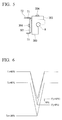
drive circuit 3 is Tc, and a junction temperature on a surface of a chip inside the case of the power element is Tj. As shown inFIG. 6 , for example, it is assumed that a temperature difference of 20°C is present between the case temperature Tc and the junction temperature Tj. - A case where the case temperature Tc of the power element that forms the
drive circuit 3 is 60°C in the heating operation and the case temperature Tc of the power element that forms thedrive circuit 3 in the defrost control is cooled to 20°C will be described. In this case, the junction temperature Tj of the power element that forms thedrive circuit 3 is changed from 80°C to 0°C. Thepower element controller 218 performs a control for increasing the temperature of the power element that forms thedrive circuit 3 by 10°C compared with that in the heating operation while therefrigerant circuit controller 217 is performing the defrost control. Then, the junction temperature Tj at a temperature of 0°C in the heating operation is changed to 10°C. Due to the increase of the junction temperature Tj, the temperature change in the junction temperature of the power element that forms thedrive circuit 3 is changed from 80°C to 70°C. As a result, the temperature change in the junction temperature is moderated by 10°C. - When the temperature change in the junction temperature of the power element is 80°C, with reference to a relationship between the temperature change in the junction temperature and the number of cycles shown in
FIG. 7 , the number of cycles is about 12000. When the temperature change in the junction temperature is 70°C, the number of cycles is about 30000. Thepower element controller 218 performs a control for increasing that temperature of the element power that forms thedrive circuit 3 by 10°C compared with that in the heating operation while therefrigerant circuit controller 217 is performing the defrost control. In this case, the temperature change in the junction temperature of the power element is moderated by 10°C from 80°C to 70°C. As a result, the lifetime of the power element increases by 2.5 times. - Hereinbefore, the processes of the
control device 216 according to this embodiment have been described. According to the processes of thecontrol device 216 according to this embodiment, therefrigerant circuit controller 217 performs the defrost control for temporarily performing the cooling operation in the heating operation, in therefrigerant circuit 1. Thepower element controller 218 performs the control for increasing the loss of the power element compared with that in the heating operation while therefrigerant circuit controller 217 is performing the defrost control. - With such a configuration, in the
refrigerant circuit 1, the temperature change in the power element generated when performing the defrost control for temporarily performing the cooling operation in the heating operation is reduced. As a result, thecontrol device 216 can lengthen the lifetime of the power element. - The embodiments of the invention have been described, but the
control device 216 includes a computer system therein. Further, a procedure of the above-described processes is stored in a computer-readable recording medium in a program format, and when the computer reads and executes the program, the processes are performed. Here, the computer-readable recording medium refers to a magnetic disk, a magneto-optical disc, a CD-ROM, a DVD-ROM, a semiconductor memory, or the like. Further, the computer program may be distributed to the computer through a communication line, and the computer that receives the distribution may execute the program. - Further, the program may realize a part of the above-described functions. In addition, the program may be a file capable of being realized by a combination with a program which is stored in advance in the computer system, a so-called differential file (differential program).
- While preferred embodiments of the invention have been described and illustrated above, it should be understood that these are exemplary of the invention and are not to be considered as limiting. Additions, omissions, substitutions, and other modifications can be made without departing from the scope of the present invention. Accordingly, the invention is not to be considered as being limited by the foregoing description, and is only limited by the scope of the appended claims.
Claims (8)
- A control device (216) comprising:a refrigerant circuit controller (217) that increases a temperature of a heat exchanger (201) in a cooling operation, the cooling operation being temporarily performed during a heating operation; anda power element controller (218) that increases a loss of a power element in the cooling operation compared with a loss of the power element in the heating operation, the power element forming an inverter circuit (3) that controls a compressor motor (210).
- The control device according to claim 1, wherein the power element controller (218) increases a switching frequency of the inverter circuit (3) in the cooling operation compared with a switching frequency of the inverter circuit (3) in the heating operation.
- The control device according to claim 1 or 2, wherein
the power element controller (218) controls the compressor motor (210) in a three-phase modulation manner in the cooling operation, and
the power element controller controls (218) the compressor motor (210) in a two-phase modulation manner in the heating operation. - The control device according to claim 1 or 3, wherein the power element controller (218) decreases a power factor of the inverter circuit (3) in the cooling operation compared with a power factor of the inverter circuit (3) in the heating operation.
- A control method comprising:increasing a temperature of a heat exchanger (201) in a cooling operation, the cooling operation being temporarily performed during a heating operation; andincreasing a loss of a power element in the cooling operation compared with a loss of the power element in the heating operation, the power element forming an inverter circuit (3) that controls a compressor motor (210).
- A program that causes a computer to execute:increasing a temperature of a heat exchanger in a cooling operation, the cooling operation being temporarily performed during a heating operation; andincreasing a loss of a power element in the cooling operation compared with a loss of the power element in the heating operation, the power element forming an inverter circuit that controls a compressor motor.
- A computer program product loadable directly into a memory of a computing system, comprising software code portions for the execution of the control method according to claim 5 when said program is executed on said computing system.
- Medium readable by a computing system, having computer-executable instructions adapted for effecting the execution by the computing system of the control method according to claim 5.
Applications Claiming Priority (1)
| Application Number | Priority Date | Filing Date | Title |
|---|---|---|---|
| JP2014254949A JP6476515B2 (en) | 2014-12-17 | 2014-12-17 | Control device, control method and program |
Publications (1)
| Publication Number | Publication Date |
|---|---|
| EP3034967A1 true EP3034967A1 (en) | 2016-06-22 |
Family
ID=55027276
Family Applications (1)
| Application Number | Title | Priority Date | Filing Date |
|---|---|---|---|
| EP15199714.5A Withdrawn EP3034967A1 (en) | 2014-12-17 | 2015-12-14 | Control device, control method, and program |
Country Status (2)
| Country | Link |
|---|---|
| EP (1) | EP3034967A1 (en) |
| JP (1) | JP6476515B2 (en) |
Cited By (1)
| Publication number | Priority date | Publication date | Assignee | Title |
|---|---|---|---|---|
| WO2026068074A1 (en) * | 2024-09-27 | 2026-04-02 | Zf Friedrichshafen Ag | Cycle process device, thermal management system, vehicle and method |
Families Citing this family (1)
| Publication number | Priority date | Publication date | Assignee | Title |
|---|---|---|---|---|
| JP7438373B2 (en) | 2020-08-21 | 2024-02-26 | 三菱電機株式会社 | Refrigeration and air conditioning equipment |
Citations (3)
| Publication number | Priority date | Publication date | Assignee | Title |
|---|---|---|---|---|
| US4604872A (en) * | 1984-02-03 | 1986-08-12 | Kabushiki Kaisha Toshiba | Heat pump type air conditioning apparatus having a controlled variable capacity compressor |
| US4850200A (en) * | 1987-07-10 | 1989-07-25 | Kabushiki Kaisha Toshiba | Refrigerating circuit device for air conditioning apparatus and control method thereof |
| JP2010025374A (en) | 2008-07-15 | 2010-02-04 | Daikin Ind Ltd | Refrigerating device |
Family Cites Families (7)
| Publication number | Priority date | Publication date | Assignee | Title |
|---|---|---|---|---|
| JPH1123075A (en) * | 1997-07-08 | 1999-01-26 | Denso Corp | Heating element cooling device |
| JP4635595B2 (en) * | 2004-12-16 | 2011-02-23 | ダイキン工業株式会社 | Heat exchange system |
| WO2010073635A1 (en) * | 2008-12-26 | 2010-07-01 | ダイキン工業株式会社 | Power converter |
| JP5445426B2 (en) * | 2010-10-27 | 2014-03-19 | 株式会社豊田自動織機 | Electric motor control device for electric compressor |
| JP2013011392A (en) * | 2011-06-29 | 2013-01-17 | Panasonic Corp | Air conditioner |
| CN104254738B (en) * | 2012-04-27 | 2017-11-03 | 大金工业株式会社 | Refrigerating plant |
| JP5970983B2 (en) * | 2012-07-03 | 2016-08-17 | 三菱電機株式会社 | Power converter |
-
2014
- 2014-12-17 JP JP2014254949A patent/JP6476515B2/en active Active
-
2015
- 2015-12-14 EP EP15199714.5A patent/EP3034967A1/en not_active Withdrawn
Patent Citations (3)
| Publication number | Priority date | Publication date | Assignee | Title |
|---|---|---|---|---|
| US4604872A (en) * | 1984-02-03 | 1986-08-12 | Kabushiki Kaisha Toshiba | Heat pump type air conditioning apparatus having a controlled variable capacity compressor |
| US4850200A (en) * | 1987-07-10 | 1989-07-25 | Kabushiki Kaisha Toshiba | Refrigerating circuit device for air conditioning apparatus and control method thereof |
| JP2010025374A (en) | 2008-07-15 | 2010-02-04 | Daikin Ind Ltd | Refrigerating device |
Cited By (1)
| Publication number | Priority date | Publication date | Assignee | Title |
|---|---|---|---|---|
| WO2026068074A1 (en) * | 2024-09-27 | 2026-04-02 | Zf Friedrichshafen Ag | Cycle process device, thermal management system, vehicle and method |
Also Published As
| Publication number | Publication date |
|---|---|
| JP6476515B2 (en) | 2019-03-06 |
| JP2016114328A (en) | 2016-06-23 |
Similar Documents
| Publication | Publication Date | Title |
|---|---|---|
| US11668500B2 (en) | Cooling system and control method therefor | |
| EP3617616B1 (en) | Refrigeration cycle device | |
| CN104566840B (en) | Refrigerant radiator, the air-conditioning and temprature control method for installing it | |
| US10314200B2 (en) | Variable frequency drive operation to avoid overheating | |
| CN106352615B (en) | Air conditioner and refrigerant heat dissipation control method thereof | |
| US8245525B2 (en) | Heat source apparatus, heat source system, and method for operating heat source apparatus | |
| CN109028452A (en) | Air-conditioning system and its refrigerant radiator and method | |
| WO2023126025A1 (en) | Refrigerant heat dissipation system for frequency converter of water chiller unit | |
| US11509251B2 (en) | Motor driving device and air conditioner | |
| CN104089346A (en) | Air conditioner and cooling method for air conditioner power component | |
| RU2017103443A (en) | SYSTEM AND METHOD FOR COOLING A COMPUTER VEHICLE DEVICE | |
| CN108025621A (en) | Air-conditioning system | |
| CN110220325B (en) | Compressor refrigerator system including thermoelectric module and corresponding control method | |
| JP6832471B1 (en) | Cooling device and cooling method | |
| JP2013213670A (en) | Inverter cooling device, inverter cooling method, and refrigerating machine | |
| JP2014089024A5 (en) | ||
| CN105588276A (en) | Air conditioner and control method thereof | |
| JP2014089024A (en) | Freezer | |
| CN112944580A (en) | Heat dissipation device, air conditioner and control method and system of heat dissipation device of air conditioner | |
| KR102312058B1 (en) | Variable speed drive for HVAC&R systems | |
| JP6476515B2 (en) | Control device, control method and program | |
| US10041840B2 (en) | Variable frequency drive temperature determination | |
| JP2015144496A (en) | Dc power supply and air conditioner using the same | |
| JP2010025374A (en) | Refrigerating device | |
| CN112665249A (en) | Multi-chamber control method and device for refrigeration system and refrigeration system |
Legal Events
| Date | Code | Title | Description |
|---|---|---|---|
| PUAI | Public reference made under article 153(3) epc to a published international application that has entered the european phase |
Free format text: ORIGINAL CODE: 0009012 |
|
| AK | Designated contracting states |
Kind code of ref document: A1 Designated state(s): AL AT BE BG CH CY CZ DE DK EE ES FI FR GB GR HR HU IE IS IT LI LT LU LV MC MK MT NL NO PL PT RO RS SE SI SK SM TR |
|
| AX | Request for extension of the european patent |
Extension state: BA ME |
|
| 17P | Request for examination filed |
Effective date: 20161219 |
|
| RBV | Designated contracting states (corrected) |
Designated state(s): AL AT BE BG CH CY CZ DE DK EE ES FI FR GB GR HR HU IE IS IT LI LT LU LV MC MK MT NL NO PL PT RO RS SE SI SK SM TR |
|
| RAP1 | Party data changed (applicant data changed or rights of an application transferred) |
Owner name: MITSUBISHI HEAVY INDUSTRIES THERMAL SYSTEMS, LTD. |
|
| STAA | Information on the status of an ep patent application or granted ep patent |
Free format text: STATUS: THE APPLICATION HAS BEEN WITHDRAWN |
|
| 18W | Application withdrawn |
Effective date: 20190909 |