EP3034910A1 - Control system for hybrid vehicle - Google Patents
Control system for hybrid vehicle Download PDFInfo
- Publication number
- EP3034910A1 EP3034910A1 EP15200424.8A EP15200424A EP3034910A1 EP 3034910 A1 EP3034910 A1 EP 3034910A1 EP 15200424 A EP15200424 A EP 15200424A EP 3034910 A1 EP3034910 A1 EP 3034910A1
- Authority
- EP
- European Patent Office
- Prior art keywords
- deviation
- drive mode
- changing value
- control unit
- electronic control
- Prior art date
- Legal status (The legal status is an assumption and is not a legal conclusion. Google has not performed a legal analysis and makes no representation as to the accuracy of the status listed.)
- Granted
Links
Images


Classifications
-
- B—PERFORMING OPERATIONS; TRANSPORTING
- B60—VEHICLES IN GENERAL
- B60W—CONJOINT CONTROL OF VEHICLE SUB-UNITS OF DIFFERENT TYPE OR DIFFERENT FUNCTION; CONTROL SYSTEMS SPECIALLY ADAPTED FOR HYBRID VEHICLES; ROAD VEHICLE DRIVE CONTROL SYSTEMS FOR PURPOSES NOT RELATED TO THE CONTROL OF A PARTICULAR SUB-UNIT
- B60W10/00—Conjoint control of vehicle sub-units of different type or different function
- B60W10/04—Conjoint control of vehicle sub-units of different type or different function including control of propulsion units
- B60W10/06—Conjoint control of vehicle sub-units of different type or different function including control of propulsion units including control of combustion engines
-
- B—PERFORMING OPERATIONS; TRANSPORTING
- B60—VEHICLES IN GENERAL
- B60W—CONJOINT CONTROL OF VEHICLE SUB-UNITS OF DIFFERENT TYPE OR DIFFERENT FUNCTION; CONTROL SYSTEMS SPECIALLY ADAPTED FOR HYBRID VEHICLES; ROAD VEHICLE DRIVE CONTROL SYSTEMS FOR PURPOSES NOT RELATED TO THE CONTROL OF A PARTICULAR SUB-UNIT
- B60W20/00—Control systems specially adapted for hybrid vehicles
- B60W20/10—Controlling the power contribution of each of the prime movers to meet required power demand
- B60W20/15—Control strategies specially adapted for achieving a particular effect
-
- B—PERFORMING OPERATIONS; TRANSPORTING
- B60—VEHICLES IN GENERAL
- B60K—ARRANGEMENT OR MOUNTING OF PROPULSION UNITS OR OF TRANSMISSIONS IN VEHICLES; ARRANGEMENT OR MOUNTING OF PLURAL DIVERSE PRIME-MOVERS IN VEHICLES; AUXILIARY DRIVES FOR VEHICLES; INSTRUMENTATION OR DASHBOARDS FOR VEHICLES; ARRANGEMENTS IN CONNECTION WITH COOLING, AIR INTAKE, GAS EXHAUST OR FUEL SUPPLY OF PROPULSION UNITS IN VEHICLES
- B60K25/00—Auxiliary drives
- B60K25/02—Auxiliary drives directly from an engine shaft
-
- B—PERFORMING OPERATIONS; TRANSPORTING
- B60—VEHICLES IN GENERAL
- B60K—ARRANGEMENT OR MOUNTING OF PROPULSION UNITS OR OF TRANSMISSIONS IN VEHICLES; ARRANGEMENT OR MOUNTING OF PLURAL DIVERSE PRIME-MOVERS IN VEHICLES; AUXILIARY DRIVES FOR VEHICLES; INSTRUMENTATION OR DASHBOARDS FOR VEHICLES; ARRANGEMENTS IN CONNECTION WITH COOLING, AIR INTAKE, GAS EXHAUST OR FUEL SUPPLY OF PROPULSION UNITS IN VEHICLES
- B60K6/00—Arrangement or mounting of plural diverse prime-movers for mutual or common propulsion, e.g. hybrid propulsion systems comprising electric motors and internal combustion engines
- B60K6/20—Arrangement or mounting of plural diverse prime-movers for mutual or common propulsion, e.g. hybrid propulsion systems comprising electric motors and internal combustion engines the prime-movers consisting of electric motors and internal combustion engines, e.g. HEVs
- B60K6/42—Arrangement or mounting of plural diverse prime-movers for mutual or common propulsion, e.g. hybrid propulsion systems comprising electric motors and internal combustion engines the prime-movers consisting of electric motors and internal combustion engines, e.g. HEVs characterised by the architecture of the hybrid electric vehicle
- B60K6/44—Series-parallel type
- B60K6/445—Differential gearing distribution type
-
- B—PERFORMING OPERATIONS; TRANSPORTING
- B60—VEHICLES IN GENERAL
- B60W—CONJOINT CONTROL OF VEHICLE SUB-UNITS OF DIFFERENT TYPE OR DIFFERENT FUNCTION; CONTROL SYSTEMS SPECIALLY ADAPTED FOR HYBRID VEHICLES; ROAD VEHICLE DRIVE CONTROL SYSTEMS FOR PURPOSES NOT RELATED TO THE CONTROL OF A PARTICULAR SUB-UNIT
- B60W10/00—Conjoint control of vehicle sub-units of different type or different function
- B60W10/04—Conjoint control of vehicle sub-units of different type or different function including control of propulsion units
- B60W10/08—Conjoint control of vehicle sub-units of different type or different function including control of propulsion units including control of electric propulsion units, e.g. motors or generators
-
- B—PERFORMING OPERATIONS; TRANSPORTING
- B60—VEHICLES IN GENERAL
- B60W—CONJOINT CONTROL OF VEHICLE SUB-UNITS OF DIFFERENT TYPE OR DIFFERENT FUNCTION; CONTROL SYSTEMS SPECIALLY ADAPTED FOR HYBRID VEHICLES; ROAD VEHICLE DRIVE CONTROL SYSTEMS FOR PURPOSES NOT RELATED TO THE CONTROL OF A PARTICULAR SUB-UNIT
- B60W10/00—Conjoint control of vehicle sub-units of different type or different function
- B60W10/30—Conjoint control of vehicle sub-units of different type or different function including control of auxiliary equipment, e.g. air-conditioning compressors or oil pumps
-
- B—PERFORMING OPERATIONS; TRANSPORTING
- B60—VEHICLES IN GENERAL
- B60W—CONJOINT CONTROL OF VEHICLE SUB-UNITS OF DIFFERENT TYPE OR DIFFERENT FUNCTION; CONTROL SYSTEMS SPECIALLY ADAPTED FOR HYBRID VEHICLES; ROAD VEHICLE DRIVE CONTROL SYSTEMS FOR PURPOSES NOT RELATED TO THE CONTROL OF A PARTICULAR SUB-UNIT
- B60W20/00—Control systems specially adapted for hybrid vehicles
- B60W20/10—Controlling the power contribution of each of the prime movers to meet required power demand
-
- B—PERFORMING OPERATIONS; TRANSPORTING
- B60—VEHICLES IN GENERAL
- B60W—CONJOINT CONTROL OF VEHICLE SUB-UNITS OF DIFFERENT TYPE OR DIFFERENT FUNCTION; CONTROL SYSTEMS SPECIALLY ADAPTED FOR HYBRID VEHICLES; ROAD VEHICLE DRIVE CONTROL SYSTEMS FOR PURPOSES NOT RELATED TO THE CONTROL OF A PARTICULAR SUB-UNIT
- B60W20/00—Control systems specially adapted for hybrid vehicles
- B60W20/40—Controlling the engagement or disengagement of prime movers, e.g. for transition between prime movers
-
- B—PERFORMING OPERATIONS; TRANSPORTING
- B60—VEHICLES IN GENERAL
- B60W—CONJOINT CONTROL OF VEHICLE SUB-UNITS OF DIFFERENT TYPE OR DIFFERENT FUNCTION; CONTROL SYSTEMS SPECIALLY ADAPTED FOR HYBRID VEHICLES; ROAD VEHICLE DRIVE CONTROL SYSTEMS FOR PURPOSES NOT RELATED TO THE CONTROL OF A PARTICULAR SUB-UNIT
- B60W30/00—Purposes of road vehicle drive control systems not related to the control of a particular sub-unit, e.g. of systems using conjoint control of vehicle sub-units
- B60W30/18—Propelling the vehicle
- B60W30/184—Preventing damage resulting from overload or excessive wear of the driveline
- B60W30/1843—Overheating of driveline components
-
- B—PERFORMING OPERATIONS; TRANSPORTING
- B60—VEHICLES IN GENERAL
- B60W—CONJOINT CONTROL OF VEHICLE SUB-UNITS OF DIFFERENT TYPE OR DIFFERENT FUNCTION; CONTROL SYSTEMS SPECIALLY ADAPTED FOR HYBRID VEHICLES; ROAD VEHICLE DRIVE CONTROL SYSTEMS FOR PURPOSES NOT RELATED TO THE CONTROL OF A PARTICULAR SUB-UNIT
- B60W50/00—Details of control systems for road vehicle drive control not related to the control of a particular sub-unit, e.g. process diagnostic or vehicle driver interfaces
- B60W50/06—Improving the dynamic response of the control system, e.g. improving the speed of regulation or avoiding hunting or overshoot
-
- F—MECHANICAL ENGINEERING; LIGHTING; HEATING; WEAPONS; BLASTING
- F16—ENGINEERING ELEMENTS AND UNITS; GENERAL MEASURES FOR PRODUCING AND MAINTAINING EFFECTIVE FUNCTIONING OF MACHINES OR INSTALLATIONS; THERMAL INSULATION IN GENERAL
- F16H—GEARING
- F16H57/00—General details of gearing
- F16H57/04—Features relating to lubrication or cooling or heating
- F16H57/0434—Features relating to lubrication or cooling or heating relating to lubrication supply, e.g. pumps; Pressure control
- F16H57/0441—Arrangements of pumps
-
- F—MECHANICAL ENGINEERING; LIGHTING; HEATING; WEAPONS; BLASTING
- F16—ENGINEERING ELEMENTS AND UNITS; GENERAL MEASURES FOR PRODUCING AND MAINTAINING EFFECTIVE FUNCTIONING OF MACHINES OR INSTALLATIONS; THERMAL INSULATION IN GENERAL
- F16H—GEARING
- F16H57/00—General details of gearing
- F16H57/04—Features relating to lubrication or cooling or heating
- F16H57/048—Type of gearings to be lubricated, cooled or heated
- F16H57/0482—Gearings with gears having orbital motion
- F16H57/0486—Gearings with gears having orbital motion with fixed gear ratio
-
- F—MECHANICAL ENGINEERING; LIGHTING; HEATING; WEAPONS; BLASTING
- F16—ENGINEERING ELEMENTS AND UNITS; GENERAL MEASURES FOR PRODUCING AND MAINTAINING EFFECTIVE FUNCTIONING OF MACHINES OR INSTALLATIONS; THERMAL INSULATION IN GENERAL
- F16H—GEARING
- F16H61/00—Control functions within control units of change-speed- or reversing-gearings for conveying rotary motion ; Control of exclusively fluid gearing, friction gearing, gearings with endless flexible members or other particular types of gearing
- F16H61/0021—Generation or control of line pressure
- F16H61/0025—Supply of control fluid; Pumps therefor
- F16H61/0031—Supply of control fluid; Pumps therefor using auxiliary pumps, e.g. pump driven by a different power source than the engine
-
- B—PERFORMING OPERATIONS; TRANSPORTING
- B60—VEHICLES IN GENERAL
- B60K—ARRANGEMENT OR MOUNTING OF PROPULSION UNITS OR OF TRANSMISSIONS IN VEHICLES; ARRANGEMENT OR MOUNTING OF PLURAL DIVERSE PRIME-MOVERS IN VEHICLES; AUXILIARY DRIVES FOR VEHICLES; INSTRUMENTATION OR DASHBOARDS FOR VEHICLES; ARRANGEMENTS IN CONNECTION WITH COOLING, AIR INTAKE, GAS EXHAUST OR FUEL SUPPLY OF PROPULSION UNITS IN VEHICLES
- B60K6/00—Arrangement or mounting of plural diverse prime-movers for mutual or common propulsion, e.g. hybrid propulsion systems comprising electric motors and internal combustion engines
- B60K6/20—Arrangement or mounting of plural diverse prime-movers for mutual or common propulsion, e.g. hybrid propulsion systems comprising electric motors and internal combustion engines the prime-movers consisting of electric motors and internal combustion engines, e.g. HEVs
- B60K6/22—Arrangement or mounting of plural diverse prime-movers for mutual or common propulsion, e.g. hybrid propulsion systems comprising electric motors and internal combustion engines the prime-movers consisting of electric motors and internal combustion engines, e.g. HEVs characterised by apparatus, components or means specially adapted for HEVs
- B60K6/38—Arrangement or mounting of plural diverse prime-movers for mutual or common propulsion, e.g. hybrid propulsion systems comprising electric motors and internal combustion engines the prime-movers consisting of electric motors and internal combustion engines, e.g. HEVs characterised by apparatus, components or means specially adapted for HEVs characterised by the driveline clutches
- B60K2006/381—Arrangement or mounting of plural diverse prime-movers for mutual or common propulsion, e.g. hybrid propulsion systems comprising electric motors and internal combustion engines the prime-movers consisting of electric motors and internal combustion engines, e.g. HEVs characterised by apparatus, components or means specially adapted for HEVs characterised by the driveline clutches characterized by driveline brakes
-
- B—PERFORMING OPERATIONS; TRANSPORTING
- B60—VEHICLES IN GENERAL
- B60W—CONJOINT CONTROL OF VEHICLE SUB-UNITS OF DIFFERENT TYPE OR DIFFERENT FUNCTION; CONTROL SYSTEMS SPECIALLY ADAPTED FOR HYBRID VEHICLES; ROAD VEHICLE DRIVE CONTROL SYSTEMS FOR PURPOSES NOT RELATED TO THE CONTROL OF A PARTICULAR SUB-UNIT
- B60W2510/00—Input parameters relating to a particular sub-units
- B60W2510/06—Combustion engines, Gas turbines
- B60W2510/0657—Engine torque
-
- B—PERFORMING OPERATIONS; TRANSPORTING
- B60—VEHICLES IN GENERAL
- B60W—CONJOINT CONTROL OF VEHICLE SUB-UNITS OF DIFFERENT TYPE OR DIFFERENT FUNCTION; CONTROL SYSTEMS SPECIALLY ADAPTED FOR HYBRID VEHICLES; ROAD VEHICLE DRIVE CONTROL SYSTEMS FOR PURPOSES NOT RELATED TO THE CONTROL OF A PARTICULAR SUB-UNIT
- B60W2510/00—Input parameters relating to a particular sub-units
- B60W2510/10—Change speed gearings
- B60W2510/107—Temperature
-
- B—PERFORMING OPERATIONS; TRANSPORTING
- B60—VEHICLES IN GENERAL
- B60W—CONJOINT CONTROL OF VEHICLE SUB-UNITS OF DIFFERENT TYPE OR DIFFERENT FUNCTION; CONTROL SYSTEMS SPECIALLY ADAPTED FOR HYBRID VEHICLES; ROAD VEHICLE DRIVE CONTROL SYSTEMS FOR PURPOSES NOT RELATED TO THE CONTROL OF A PARTICULAR SUB-UNIT
- B60W2710/00—Output or target parameters relating to a particular sub-units
- B60W2710/06—Combustion engines, Gas turbines
-
- B—PERFORMING OPERATIONS; TRANSPORTING
- B60—VEHICLES IN GENERAL
- B60W—CONJOINT CONTROL OF VEHICLE SUB-UNITS OF DIFFERENT TYPE OR DIFFERENT FUNCTION; CONTROL SYSTEMS SPECIALLY ADAPTED FOR HYBRID VEHICLES; ROAD VEHICLE DRIVE CONTROL SYSTEMS FOR PURPOSES NOT RELATED TO THE CONTROL OF A PARTICULAR SUB-UNIT
- B60W2710/00—Output or target parameters relating to a particular sub-units
- B60W2710/08—Electric propulsion units
-
- B—PERFORMING OPERATIONS; TRANSPORTING
- B60—VEHICLES IN GENERAL
- B60W—CONJOINT CONTROL OF VEHICLE SUB-UNITS OF DIFFERENT TYPE OR DIFFERENT FUNCTION; CONTROL SYSTEMS SPECIALLY ADAPTED FOR HYBRID VEHICLES; ROAD VEHICLE DRIVE CONTROL SYSTEMS FOR PURPOSES NOT RELATED TO THE CONTROL OF A PARTICULAR SUB-UNIT
- B60W2710/00—Output or target parameters relating to a particular sub-units
- B60W2710/30—Auxiliary equipments
-
- F—MECHANICAL ENGINEERING; LIGHTING; HEATING; WEAPONS; BLASTING
- F16—ENGINEERING ELEMENTS AND UNITS; GENERAL MEASURES FOR PRODUCING AND MAINTAINING EFFECTIVE FUNCTIONING OF MACHINES OR INSTALLATIONS; THERMAL INSULATION IN GENERAL
- F16H—GEARING
- F16H37/00—Combinations of mechanical gearings, not provided for in groups F16H1/00 - F16H35/00
- F16H37/02—Combinations of mechanical gearings, not provided for in groups F16H1/00 - F16H35/00 comprising essentially only toothed or friction gearings
- F16H37/06—Combinations of mechanical gearings, not provided for in groups F16H1/00 - F16H35/00 comprising essentially only toothed or friction gearings with a plurality of driving or driven shafts; with arrangements for dividing torque between two or more intermediate shafts
- F16H37/08—Combinations of mechanical gearings, not provided for in groups F16H1/00 - F16H35/00 comprising essentially only toothed or friction gearings with a plurality of driving or driven shafts; with arrangements for dividing torque between two or more intermediate shafts with differential gearing
- F16H37/0833—Combinations of mechanical gearings, not provided for in groups F16H1/00 - F16H35/00 comprising essentially only toothed or friction gearings with a plurality of driving or driven shafts; with arrangements for dividing torque between two or more intermediate shafts with differential gearing with arrangements for dividing torque between two or more intermediate shafts, i.e. with two or more internal power paths
- F16H37/084—Combinations of mechanical gearings, not provided for in groups F16H1/00 - F16H35/00 comprising essentially only toothed or friction gearings with a plurality of driving or driven shafts; with arrangements for dividing torque between two or more intermediate shafts with differential gearing with arrangements for dividing torque between two or more intermediate shafts, i.e. with two or more internal power paths at least one power path being a continuously variable transmission, i.e. CVT
- F16H2037/0866—Power-split transmissions with distributing differentials, with the output of the CVT connected or connectable to the output shaft
-
- F—MECHANICAL ENGINEERING; LIGHTING; HEATING; WEAPONS; BLASTING
- F16—ENGINEERING ELEMENTS AND UNITS; GENERAL MEASURES FOR PRODUCING AND MAINTAINING EFFECTIVE FUNCTIONING OF MACHINES OR INSTALLATIONS; THERMAL INSULATION IN GENERAL
- F16H—GEARING
- F16H61/00—Control functions within control units of change-speed- or reversing-gearings for conveying rotary motion ; Control of exclusively fluid gearing, friction gearing, gearings with endless flexible members or other particular types of gearing
- F16H61/0021—Generation or control of line pressure
- F16H2061/0037—Generation or control of line pressure characterised by controlled fluid supply to lubrication circuits of the gearing
-
- F—MECHANICAL ENGINEERING; LIGHTING; HEATING; WEAPONS; BLASTING
- F16—ENGINEERING ELEMENTS AND UNITS; GENERAL MEASURES FOR PRODUCING AND MAINTAINING EFFECTIVE FUNCTIONING OF MACHINES OR INSTALLATIONS; THERMAL INSULATION IN GENERAL
- F16H—GEARING
- F16H3/00—Toothed gearings for conveying rotary motion with variable gear ratio or for reversing rotary motion
- F16H3/44—Toothed gearings for conveying rotary motion with variable gear ratio or for reversing rotary motion using gears having orbital motion
- F16H3/72—Toothed gearings for conveying rotary motion with variable gear ratio or for reversing rotary motion using gears having orbital motion with a secondary drive, e.g. regulating motor, in order to vary speed continuously
- F16H3/727—Toothed gearings for conveying rotary motion with variable gear ratio or for reversing rotary motion using gears having orbital motion with a secondary drive, e.g. regulating motor, in order to vary speed continuously with at least two dynamo electric machines for creating an electric power path inside the gearing, e.g. using generator and motor for a variable power torque path
-
- F—MECHANICAL ENGINEERING; LIGHTING; HEATING; WEAPONS; BLASTING
- F16—ENGINEERING ELEMENTS AND UNITS; GENERAL MEASURES FOR PRODUCING AND MAINTAINING EFFECTIVE FUNCTIONING OF MACHINES OR INSTALLATIONS; THERMAL INSULATION IN GENERAL
- F16H—GEARING
- F16H57/00—General details of gearing
- F16H57/04—Features relating to lubrication or cooling or heating
- F16H57/0434—Features relating to lubrication or cooling or heating relating to lubrication supply, e.g. pumps; Pressure control
- F16H57/0446—Features relating to lubrication or cooling or heating relating to lubrication supply, e.g. pumps; Pressure control the supply forming part of the transmission control unit, e.g. for automatic transmissions
-
- Y—GENERAL TAGGING OF NEW TECHNOLOGICAL DEVELOPMENTS; GENERAL TAGGING OF CROSS-SECTIONAL TECHNOLOGIES SPANNING OVER SEVERAL SECTIONS OF THE IPC; TECHNICAL SUBJECTS COVERED BY FORMER USPC CROSS-REFERENCE ART COLLECTIONS [XRACs] AND DIGESTS
- Y02—TECHNOLOGIES OR APPLICATIONS FOR MITIGATION OR ADAPTATION AGAINST CLIMATE CHANGE
- Y02T—CLIMATE CHANGE MITIGATION TECHNOLOGIES RELATED TO TRANSPORTATION
- Y02T10/00—Road transport of goods or passengers
- Y02T10/60—Other road transportation technologies with climate change mitigation effect
- Y02T10/62—Hybrid vehicles
-
- Y—GENERAL TAGGING OF NEW TECHNOLOGICAL DEVELOPMENTS; GENERAL TAGGING OF CROSS-SECTIONAL TECHNOLOGIES SPANNING OVER SEVERAL SECTIONS OF THE IPC; TECHNICAL SUBJECTS COVERED BY FORMER USPC CROSS-REFERENCE ART COLLECTIONS [XRACs] AND DIGESTS
- Y10—TECHNICAL SUBJECTS COVERED BY FORMER USPC
- Y10S—TECHNICAL SUBJECTS COVERED BY FORMER USPC CROSS-REFERENCE ART COLLECTIONS [XRACs] AND DIGESTS
- Y10S903/00—Hybrid electric vehicles, HEVS
- Y10S903/902—Prime movers comprising electrical and internal combustion motors
Definitions
- the invention relates to a control system for a hybrid vehicle including an engine and at least two motors or motor generators as driving force sources.
- JP 8-295140 A and Japanese Patent Application Publication No. 2014-848 ( JP 2014-848 A ) describe a hybrid vehicle including an engine and two motor generators as driving force sources.
- the engine and the first motor generator are respectively coupled to two rotating elements of a power split mechanism formed of a single-pinion-type planetary gear mechanism, and the second motor generator is coupled to a gear train coupled to drive wheels and an output element of the power split mechanism.
- the thus configured hybrid vehicle is allowed to select one of a hybrid mode and a one-motor mode.
- the hybrid vehicle travels by transmitting the output torque of the engine to the drive wheels as a result of outputting reaction torque from the first motor generator.
- the one-motor mode the hybrid vehicle travels by transmitting the output torque of the second motor generator to the drive wheels in a state where the engine is stopped.
- the hybrid vehicle described in JP 8-295140 A is configured to be able to transmit the output torque of the first motor generator to the drive wheels.
- fixing means such as a one-way clutch and a brake, for stopping an output shaft of the engine is provided.
- the hybrid vehicle is able to travel by transmitting the output torque of both the first motor generator and the second motor generator to the drive wheels without driving the engine, so it is possible to suppress deterioration of fuel economy.
- the hybrid vehicle described in JP 2014-848 A includes a mechanical oil pump that rotates integrally with the engine and an electric oil pump that is driven by energization and that has a smaller capacity than the mechanical oil pump.
- the hybrid vehicle is configured to, even when a drive mode that is determined on the basis of a required driving force and a vehicle speed is the one-motor mode but when the viscosity of oil is high, change the drive mode to the hybrid mode. This is because a load on the electric oil pump increases as the viscosity of oil becomes higher and there is a possibility that the durability of the electric oil pump decreases.
- the oil pumps described in JP 2014-848 A may be mounted on the hybrid vehicle described in JP 8-295140 A . Because a torque that acts on a differential mechanism at the time when the two-motor mode in which a driving torque is output from each of the motor generators is selected is larger than a torque that acts on the differential mechanism at the time when the one-motor mode is selected, oil is supplied from the electric oil pump to the differential mechanism when the two-motor mode is selected. On the other hand, there is an inevitable delay from when driving of the electric oil pumps is started to when oil reaches the differential mechanism.
- the differential mechanism transmits torque in a non-lubricated state or non-cooled state until oil reaches the differential mechanism, so there is a possibility of a decrease in durability.
- the vehicle is caused to travel while another drive mode is set in order to suppress a decrease in the durability of the differential mechanism in this way, there is a possibility that a period during which the hybrid vehicle is allowed to be caused to travel in the two-motor mode shortens or an opportunity to cause the hybrid vehicle to travel in the two-motor mode reduces.
- the invention provides a control system for a hybrid vehicle, which is able to extend a period during which the hybrid vehicle travels in a two-motor drive mode or increase an opportunity to cause the hybrid vehicle to travel in the two-motor drive mode.
- a control system related to the present invention is for a hybrid vehicle.
- the vehicle including an engine, an output member, a power split mechanism, a brake mechanism, a first motor, a second motor, a first oil pump and a second oil pump, the power split mechanism including a first rotating element, a second rotating element and a third rotating element.
- the power split mechanism is configured to carry out differential action.
- An output torque of the engine is transmitted to the first rotating element.
- the first motor has a power generation function coupled to the second rotating element.
- the output member is coupled to the third rotating element.
- the brake mechanism is configured to selectively stop rotation of the first rotating element.
- the second motor is configured to add a driving torque for propelling the vehicle to a torque of the output member.
- the first oil pump is coupled to the first rotating element.
- the first oil pump is configured to be driven by the output torque of the engine to supply oil to the power split mechanism.
- the second oil pump is configured to be driven through energization to supply oil to the power split mechanism.
- the control system includes an electronic control unit.
- the electronic control unit is configured to select a second drive mode when any one of the following conditions i), ii) is satisfied: i) a required driving force is larger than the required driving force at which a first drive mode is selected or a vehicle speed is larger than the vehicle speed at which the first drive mode is selected; and ii) the required driving force is lower than the required driving force at which a third drive mode is selected or the vehicle speed is lower than the vehicle speed at which the third drive mode is selected.
- the electronic control unit is configured to, when any one of the following conditions iii) to vi) is satisfied, activate the second oil pump to start supplying oil from the second oil pump to the power split mechanism: iii) the required driving force becomes larger than or equal to a first pump changing value when the first drive mode is selected, the first pump changing value being smaller than a first drive changing value at which a drive mode is changed from the first drive mode to the second drive mode; iv) the vehicle speed becomes higher than or equal to a second pump changing value when the first drive mode is selected, the second pump changing value being lower than a second drive changing value at which the drive mode is changed from the first drive mode to the second drive mode; v) the required driving force becomes smaller than or equal to a third pump changing value when the third drive mode is selected, the third pump changing value being larger than a third drive changing value at which the drive mode is changed from the third drive mode to the second drive mode; and vi) the vehicle speed becomes lower than or equal to a fourth pump changing value when the third drive mode is selected, the
- the first drive mode is a mode in which fixing of the first rotating element by the brake mechanism is released and the vehicle travels by using the driving torque of the second motor.
- the second drive mode is a mode in which a torque output from the first motor is transmitted to the output member via the power split mechanism in a state where the first rotating element is fixed by the brake mechanism and the vehicle travels by using the driving torque output from the second motor.
- the third drive mode is a mode in which the vehicle travels by using the output torque of the engine or the output torque of both the engine and the second motor in a state where fixing of the first rotating element by the brake mechanism is released.
- the electronic control unit may be configured to execute the following vii) or viii): vii) a first deviation or a second deviation is respectively set such that a time from when the second oil pump is activated to when oil begins to be supplied to the power split mechanism is shorter than a first time or a second time, the first deviation is a deviation between the first drive changing value and the first pump changing value, the second deviation is a deviation between the second drive changing value and the second pump changing value, the first time is a time that is required for the required driving force to change from the first pump changing value to the first drive changing value in the first drive mode, the second time is a time that is required for the vehicle speed to change from the second pump changing value to the second drive changing value; viii) a third deviation or a fourth deviation is respectively set such that a time from when the second oil pump is activated to when oil begins to be supplied to the power split mechanism is shorter than a third time or a fourth time, the third deviation is a deviation between the third drive changing value and the third pump changing value, the
- the electronic control unit is configured to detect any one of a temperature of the oil, an ambient temperature and a temperature of the second oil pump.
- the electronic control unit may be configured to set at least any one of the first deviation, second deviation, third deviation and fourth deviation such that the at least any one of the first deviation, second deviation, third deviation and fourth deviation increases as detected temperature detected by the electronic control unit decreases.
- the electronic control unit may be configured to detect an elapsed time or travel distance from when the second oil pump is stopped.
- the electronic control unit may be configured to set at least any one of the first deviation, second deviation, third deviation and fourth deviation such that the at least any one of the first deviation, second deviation, third deviation and fourth deviation increases as detected elapsed time or travel distance detected by the electronic control unit extends.
- the electronic control unit may be configured to detect a vehicle stop time.
- the electronic control unit may be configured to set at least any one of the first deviation, second deviation, third deviation and fourth deviation such that the at least any one of the first deviation, second deviation, third deviation and fourth deviation increases as detected vehicle stop time detected by the electronic control unit gets longer.
- the electronic control unit is configured to estimate an amount of change in the required driving force toward the first drive changing value in a state where the first drive mode is selected or an amount of change in the required driving force toward the third drive changing value in a state where the third drive mode is selected.
- the electronic control unit may be configured to set at least any one of the first deviation, second deviation, third deviation and fourth deviation such that the at least any one of the first deviation, second deviation, third deviation and fourth deviation increases as estimated amount of change in the required driving force estimated by the electronic control unit increases.
- the electronic control unit may be configured to detect a gradient of a traveling road surface.
- the electronic control unit may be configured to set at least any one of the first deviation, second deviation, third deviation and fourth deviation such that the at least any one of the first deviation, second deviation, third deviation and fourth deviation increases as detected gradient of the traveling road surface detected by the electronic control unit increases.
- the electronic control unit may be configured to detect a rate of change in accelerator position.
- the electronic control unit may be configured to set at least any one of the first deviation, second deviation, third deviation and fourth deviation such that the at least any one of the first deviation, second deviation, third deviation and fourth deviation increases as detected rate of change in accelerator position detected by the electronic control unit increases.
- the electronic control unit may be configured to set at least any one of the first pump changing value, the second pump changing value, the third pump changing value and the fourth pump changing value at the time of a startup of the vehicle.
- the electronic control unit may be configured to continue driving the second oil pump until a predetermined period elapsed from when the drive mode is changed from the second drive mode to the first drive mode.
- the electronic control unit may be configured to extend the predetermined period as an output torque of the first motor and a rotation speed of the first motor increase at the time when the vehicle is traveling in the second drive mode.
- the electronic control unit may be configured to estimate a temperature of the power split mechanism, and the electronic control unit may be configured to cause the second oil pump to be driven until estimated temperature estimated by the electronic control unit becomes lower than or equal to a predetermined temperature.
- the electronic control unit may be configured to continue driving the second oil pump until an output torque of the first motor and a rotation speed of the first motor become smaller than or equal to corresponding predetermined values, in transition of a change from the second drive mode to the first drive mode.
- a hybrid drive system is a so-called two-motor-type drive system, and includes an engine (ENG) 1 and two motors 2, 3 as driving force sources.
- the engine 1 is an internal combustion engine, such as a gasoline engine or a diesel engine.
- the first motor 2 may be a motor generator (MG) that is able to regenerate energy or output power.
- the second motor 3 may be similarly a motor generator (MG).
- the hybrid drive system includes a power split mechanism 4 that distributes power, output from the engine 1, to the first motor 2 and an output member.
- the power split mechanism 4 may be formed of a differential mechanism, such as a planetary gear mechanism, and is formed of a single-pinion-type planetary gear mechanism in the example shown in FIG. 9 .
- a plurality of (for example, three) pinion gears 7 that are in mesh with a sun gear 5 and a ring gear 6 are arranged between these sun gear 5 and ring gear 6.
- Those pinion gears 7 are supported by a carrier 8 so as to be rotatable and revolvable.
- a structure of supporting the pinion gears 7 by the carrier 8 is similar to a structure in a generally known planetary gear mechanism. The structure will be simply described.
- Pinion pins are supported by the carrier 8, and each of the pinion gears 7 is rotatably fitted to the outer peripheral side of a corresponding one of the pinion pins via a bearing, such as a needle bearing.
- Each of the pinion pins has an oil hole along its central axis. Another oil hole extends from each oil hole to the outer periphery. Lubricating oil is supplied to the bearings, tooth flanks, and the like, via these oil holes.
- the carrier 8 is a so-called input element. Power from the engine 1 is transmitted to the carrier 8. That is, an output shaft (crankshaft) 9 of the engine 1 and the carrier 8 are coupled to each other.
- the carrier 8 is an example of a first rotating element when the invention is implemented.
- a brake mechanism 10 is provided between the carrier 8 and the engine 1. The brake mechanism 10 selectively stops rotation of the carrier 8.
- the brake mechanism 10 may be any one of a friction brake, a dog brake and a one-way clutch.
- the first motor 2 is arranged along the same axis as the power split mechanism 4 across the power split mechanism 4 from the engine 1.
- the first motor 2 is coupled to the sun gear 5. Therefore, the sun gear 5 is a so-called reaction element, and the sun gear 5 is an example of a second rotating element when the invention is implemented.
- a rotor shaft of the first motor 2 and a sun gear shaft to which the rotor shaft is coupled are hollow shafts.
- a pump shaft 11 is inserted inside the hollow shafts. One end of the pump shaft 11 is coupled to the engine 1.
- a mechanical oil pump (hereinafter, referred to as MOP) 12 is coupled to the other end of the pump shaft 11.
- the MOP 12 is an example of a first oil pump when the invention is implemented.
- the MOP 12 is driven by the engine 1 to generate hydraulic pressure for control, hydraulic pressure for lubrication and hydraulic pressure for cooling.
- an electric oil pump (hereinafter, referred to as EOP) 13 is provided in parallel with the MOP 12.
- the electric oil pump 13 is driven by energization.
- the EOP 13 is an example of a second oil pump when the invention is implemented, and is smaller in capacity than the MOP 12.
- the ring gear 6 in the planetary gear mechanism that constitutes the power split mechanism 4 is a so-called output element.
- An output gear 14 is integrally provided with the ring gear 6.
- the output gear 14 is an external gear.
- the ring gear 6 is an example of a third rotating element when the invention is implemented.
- the output gear 14 is an example of an output member when the invention is implemented.
- the output gear 14 is coupled to a differential gear 16 via a counter gear unit 15. That is, a driven gear 18 connected to a counter shaft 17 is in mesh with the output gear 14.
- a drive gear 19 having a smaller diameter than the driven gear 18 is connected to the counter shaft 17.
- the drive gear 19 is in mesh with a ring gear 20 in the differential gear 16.
- a driving force is output from the differential gear 16 to right and left drive wheels 21.
- Another drive gear 22 is in mesh with the driven gear 18.
- the second motor 3 is coupled to the drive gear 22. That is, torque of the second motor 3 is added to torque that is output from the output gear 14.
- the first motor 2 and the second motor 3 are electrically connected to each other via an electrical storage device (not shown) or an inverter (not shown), and are configured to be able to supply electric power generated by the first motor 2 to the second motor 3.
- the above-described hybrid vehicle is able to selectively set one of three drive modes, that is, a hybrid mode (HV mode), a two-motor mode and a one-motor mode.
- the HV mode is a drive mode in which power output from the engine 1 is distributed by the power split mechanism 4 to the first motor 2 side and the output gear 14 side, electric power generated by the first motor 2 functioning as a power generator is supplied to the second motor 3, and the output torque of the second motor 3 is added to the torque of the output gear 14 in the counter gear unit 15. That is, the HV mode is a mode in which the hybrid vehicle travels by substantially transmitting power (torque), output from the engine 1, to the drive wheels.
- the second motor 3 may output torque by supplying the second motor 3 with electric power output from the electrical storage device (not shown) in addition to electric power generated by the first motor 2. That is, power (torque) output from the engine 1 and power (torque) output from the second motor 3 may be transmitted to the drive wheels.
- a state where the hybrid vehicle is traveling in the HV mode is an example of a third drive mode when the invention is implemented.
- the two-motor mode is a mode in which the first motor 2 and the second motor 3 are operated as driving force sources for propelling the hybrid vehicle, and the hybrid vehicle travels by the use of the power of these two motors 2, 3.
- the carrier 8 in order to transmit the output torque of the first motor 2 to the drive wheels 21, the carrier 8 is fixed by the brake mechanism 10.
- a state where the hybrid vehicle is traveling in the two-motor mode is an example of a second drive mode when the invention is implemented.
- the one-motor mode is a mode in which the hybrid vehicle travels by using the second motor 3 as a driving force source.
- control over the output torque of the engine 1 and first motor 2 is stopped. In this case, rotation of the engine 1 stops, and the first motor 2 is co-rotated.
- fixing of the output shaft of the engine 1 by the brake mechanism 10 is released, and this drive mode is an example of a first drive mode when the invention is implemented.
- Driving torque, fuel economy, and the like are different from one another among these drive modes, so regions of those drive modes are determined by a vehicle speed, a driving force, and the like, and the drive mode is selected on the basis of a required driving force, represented by an accelerator position, and a vehicle speed.
- FIG. 2 shows the regions of the drive modes, determined in advance by a vehicle speed V and a driving force F.
- the region indicated by the sign AHV is the HV mode region
- the region indicated by the sign A2M is the two-motor mode region
- the region indicated by the sign A1M is the one-motor mode region.
- the HV mode is selected when the vehicle speed is relatively high and the required driving force is relatively large, a large load is exerted on the components of the power split mechanism 4 at that time.
- the MOP 12 is driven with rotation of the carrier 8. Therefore, in the HV mode, oil is supplied from the MOP 12 to the power split mechanism 4, and lubrication and cooling are performed by the oil.
- the one-motor mode is selected when the vehicle speed is relatively low and the required driving force is relatively small.
- torque is input from the ring gear 6 to the power split mechanism 4; however, torque (reaction torque) against the input torque is not output from the engine 1 or the first motor 2. Therefore, no large load is exerted on the power split mechanism 4, and a large amount of oil is not required for lubrication and cooling.
- the power split mechanism 4 is covered with a case (not shown), and oil is flying inside the case in order to cool other gears and heat generating members. Therefore, in the one-motor mode, even when oil is not actively supplied to the power split mechanism 4 with the use of the MOP 12 or the EOP 13, the power split mechanism 4 is lubricated or cooled by oil flying inside the case.
- the two-motor mode is selected when the vehicle speed is higher than the vehicle speed in the one-motor mode and lower than the vehicle speed in the HV mode and the required driving force is larger than the required driving force in the one-motor mode and smaller than the required driving force in the HV mode.
- the carrier 8 is fixed by engaging the brake mechanism 10 in order to transmit the output torque of the first motor 2 to the drive wheels 21, a large load is exerted on the power split mechanism 4.
- the MOP 12 is not driven. Therefore, in the two-motor mode, the power split mechanism 4 is lubricated or cooled by supplying the power split mechanism 4 with oil from the EOP 13.
- An electronic control unit (ECU) 23 is provided as a controller.
- the ECU 23 is used to select any one of these drive modes and control portions of the hybrid drive system and the EOP 13 such that the selected drive mode is achieved.
- the ECU 23 includes a first control unit 23a, a second control unit 23b, a plurality of detection units 23c, a plurality of estimation units 23d, and the like.
- the first control unit 23a selects a drive mode.
- the second control unit 23b controls the driving and stop of the EOP 13.
- the plurality of detection units 23c detect electrical signals from sensors (not shown).
- the plurality of estimation units 23d estimate various states on the basis of the input electrical signals, and the like.
- the ECU 23 is mainly formed of a microcomputer.
- the ECU 23 is configured to perform a computation on the basis of input data and data, such as a prestored map, and output the computed result as a control command signal to the engine 1, each of the motors 2, 3, the electrical storage device or the inverter for each of the motors 2, 3, the brake mechanism 10, the EOP 13, or the like.
- data that are input to the ECU 23, that is, data that are used in control include the vehicle speed, the accelerator position, the rotation speeds of the motors 2, 3, the driving currents of the motors 2, 3, the temperature (oil temperature) of lubricating oil), the temperature (ambient temperature) of an environment in which the hybrid vehicle is placed, a traveling road surface condition (gradient) that is detected by a navigation system, and the like.
- EOP driving region a region AE in which the EOP 13 (described later) is driven
- a map for determining an adjustment value ⁇ A (described later) a map for determining an adjustment value ⁇ A (described later)
- determination thresholds for time and temperature are stored in advance.
- a control system for a hybrid vehicle is configured to, when a predetermined condition is satisfied in a state where the one-motor mode or the HV mode is selected, activates the EOP 13 to start supplying oil from the EOP 13 to the power split mechanism 4. That is, before the drive mode is changed to the two-motor mode, the EOP 13 is configured to be activated to start supplying oil to the power split mechanism 4.
- the predetermined condition is, for example, a condition that the required driving force in the case where the one-motor mode is selected is larger than or equal to a predetermined value smaller than a value at which the drive mode is changed from the one-motor mode to the two-motor mode, a condition that the vehicle speed in the case where the one-motor mode is selected is higher than or equal to a predetermined value lower than a value at which the drive mode is changed from the one-motor mode to the two-motor mode, a condition that the required driving force in the case where the HV mode is selected is smaller than or equal to a predetermined value larger than a value at which the drive mode is changed from the HV mode to the two-motor mode, a condition that the vehicle speed in the case where the HV mode is selected is lower than or equal to a value higher than a vehicle speed at which the drive mode is changed from the HV mode to the two-motor mode, or the like.
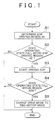
- FIG. 1 shows a flowchart for illustrating an example of control that is executed in the control system according to the invention.
- the ECU 23 is configured to execute the flowchart as the controller.
- the example shown in FIG. 1 is repeatedly executed at predetermined time intervals while the EOP 13 is stopped.
- the EOP 13 is configured to be driven in response to the required driving force and the vehicle speed, and, initially, the EOP driving region AE is determined (step S1).
- the EOP driving region AE is desirably set to a region wider than a region A2M in which the two-motor mode is selected.
- An example in which the EOP driving region AE is determined in that way is indicated by the dashed line in FIG. 2 .
- a lower limit value of the EOP driving region AE is determined within a region A1M in which the one-motor mode is selected.
- An upper limit value of the EOP driving region AE is determined within a region AHV in which the HV mode is set.
- the lower limit value of the EOP driving region AE is an example of each of a first pump changing value and a second pump changing value when the invention is implemented.
- the upper limit value of the EOP driving region AE is an example of each of a third pump changing value and a fourth pump changing value when the invention is implemented.
- a lower limit value of the region A2M in which the two-motor mode is selected is an example of each of a first drive changing value and a second drive changing value when the invention is implemented.
- An upper limit value of the region A2M is an example of each of a third drive changing value and a fourth drive changing value when the invention is implemented.
- the EOP driving region AE may be fixed or may be configured such that the upper limit value and lower limit value of the EOP driving region AE are determined as values that are increased or reduced in driving force or vehicle speed in response to various conditions from the region A2M in which the two-motor mode is selected.
- an amount (deviation) by which the driving force or vehicle speed is increased or reduced is referred to as adjustment value ⁇ A.
- the EOP driving region AE is determined such that the EOP 13 is activated before the drive mode changes from the one-motor mode or the HV mode to the two-motor mode and excessive driving of the EOP 13 is suppressed. Therefore, the EOP driving region AE is desirably determined such that a time from when the driving of the EOP 13 is started to when oil begins to be supplied to the power split mechanism 4 rather than a time that is taken for the drive mode to change from the one-motor mode or the HV mode to the two-motor mode is shortened.
- the viscosity of oil increases as the temperature of oil decreases. Because a viscous drag between oil and an oil passage increases as the viscosity of oil increases, a time from when the driving of the EOP 13 is started to when oil reaches the power split mechanism 4 extends. Therefore, in order for oil output from the EOP 13 to be supplied to the power split mechanism 4 at the time when the drive mode is changed to the two-motor mode, the driving of the EOP 13 is desirably started earlier as the temperature of oil decreases.
- the EOP driving region AE is determined such that the adjustment value ⁇ A is increased as the temperature of oil decreases.
- the abscissa axis represents the temperature of oil
- the ordinate axis represents the adjustment value ⁇ A.
- the adjustment value ⁇ A in FIG. 3 may be determined by obtaining a time that is taken for oil to flow from the EOP 13 to the power split mechanism 4 for each temperature of oil, subsequently obtaining the rate of change in driving force as a result of ordinary operation and then integrating the obtained time with the rate of change.
- the adjustment value ⁇ A may be determined by integrating the obtained time with an acceleration based on a current driving force.
- a driving force or a vehicle speed at which oil is supplied from the EOP 13 to the power split mechanism 4 at the time when the drive mode is changed to the two-motor mode may be obtained through an experiment, simulation, or the like, by using a driving force and the temperature of oil as parameters or using a vehicle speed and the temperature of oil as parameters, and then a difference between the driving force or vehicle speed and the lower limit value or upper limit value of the region A2M in which the two-motor mode is selected may be determined as the adjustment value ⁇ A.
- the adjustment value ⁇ A determined as described above is added to the upper limit value of the region A2M in which the two-motor mode is selected or subtracted from the lower limit value of the region A2M.
- the EOP driving region AE is determined.
- the temperature of oil may be estimated by detecting the ambient temperature or the temperature of the EOP 13. Therefore, not limited to the configuration that the adjustment value ⁇ A is determined by using the temperature of oil as a parameter as described above, the adjustment value ⁇ A may be determined on the basis of another parameter that contributes to the temperature of oil, such as the ambient temperature and the temperature of the EOP 13.
- the EOP 13 draws oil and then discharges the oil, and oil inevitably leaks from the EOP 13 or the oil passage, so, when the EOP 13 is stopped, oil is drained from the EOP 13 or the oil passage in response to the stopped time. Therefore, when the EOP 13 is driven again, oil is filled inside the EOP 13 and inside the oil passage and then oil is supplied to the power split mechanism 4, so, as a time during which the EOP 13 is stopped extends, a time from when the driving of the EOP 13 is started again to when oil is supplied to the power split mechanism 4 extends.
- the EOP driving region AE is desirably determined by obtaining the adjustment value ⁇ A on the basis of an elapsed time from when the EOP 13 is stopped, a travel distance or stopped time from when the EOP 13 is stopped, or the like, and then adding the adjustment value ⁇ A to the upper limit value of the region A2M in which the two-motor mode is selected or subtracting the adjustment value ⁇ A from the lower limit value of the region A2M.
- FIG. 4 shows an example of the above configuration.
- the abscissa axis represents a travel distance from when the EOP 13 is stopped, and the ordinate axis represents an adjustment value ⁇ A.
- the adjustment value ⁇ A may be increased in proportion to a travel distance as shown in FIG. 4 or may be increased quadratically.
- the adjustment value ⁇ A is set to the same value as the adjustment value ⁇ A that is determined on the basis of a time by which it may be determined that oil has been completely drained from the EOP 13 and the oil passage.
- the adjustment value ⁇ A is desirably determined such that oil reliably reaches the power split mechanism 4 at the time when the drive mode is changed from the one-motor mode to the two-motor mode.
- the adjustment value ⁇ A just needs to be determined on the basis of the above-described control, or the like.
- the required driving force changes toward the region A2M in which the two-motor mode is selected.
- the amount of change in the required driving force increases, there is a higher possibility that the drive mode is changed to the two-motor mode or there is a higher possibility that the drive mode is changed to the two-motor mode in a short time.
- the traveling road is an uphill
- the gradient of the uphill increases, there is a higher possibility that the required driving force increases.
- the required driving force increases in that way, there is a higher possibility that the drive mode is changed from the one-motor mode to the two-motor mode.
- the required driving force reduces or there is a higher possibility that regenerative brake is carried out.
- the required driving force reduces in that way or regenerative brake is carried out, there is a higher possibility that the drive mode is changed from the HV mode to the two-motor mode. Therefore, as the amount of change in the required driving force increases, the adjustment value ⁇ A is desirably increased.
- FIG. 5 and FIG. 6 An example in which the adjustment value ⁇ A is determined in response to the amount of change in the required driving force in that way is shown in FIG. 5 and FIG. 6 .
- the adjustment value ⁇ A is determined in response to the gradient of the uphill.
- a hatched amount is the adjustment value ⁇ A.
- This map is obtained as follows.
- an amount by which the driving force is increased is obtained by an experiment, simulation, or the like, and the amount of increase in the driving force may be determined as the adjustment value ⁇ A.
- the lower limit value of the EOP driving region AE may be determined by subtracting the adjustment value ⁇ A from the lower limit value of the region A2M in which the two-motor mode is selected.
- the gradient of a traveling road surface may be detected on the basis of a sensor that is mounted on the vehicle and that detects the gradient, a navigation system, or the like.
- the adjustment value ⁇ A may be determined so as to increase as the amount of change in accelerator operation amount increases, and the EOP driving region AE may be determined by adding the adjustment value ⁇ A to the upper limit value of the region A2M in which the two-motor mode is selected or subtracting the adjustment value ⁇ A from the lower limit value of the region A2M.
- the adjustment value ⁇ A may be increased quadratically in response to the amount of change in accelerator operation amount as shown in FIG. 6 or may be increased in proportion to the amount of change in accelerator operation amount.
- step S2 it is determined whether an operating state based on the required driving force and the vehicle speed falls within the EOP driving region AE (step S2).
- step S3 the driving of the EOP 13 is started (step S3).
- step S4 it is determined whether the operating state falls within the region A2M in which the two-motor mode is selected (step S4).
- step S4 When negative determination is made in step S4 as a result of the fact that the operating state falls outside the region A2M in which the two-motor mode is selected, that is, when the operating state falls within the region A1M in which the one-motor mode is selected or the region AHV in which the HV mode is selected, the routine is once ended directly. In this case, while the EOP 13 remains being driven, the hybrid vehicle travels in the one-motor mode or the HV mode. In contrast, when affirmative determination is made in step S4 as a result of the fact that the operating state falls within the region A2M in which the two-motor mode is selected, the drive mode is changed to the two-motor mode (step S5), and then the routine is once ended.
- the EOP 13 is driven before the drive mode is changed to the two-motor mode. Therefore, it is possible to supply oil to the power split mechanism 4 with no delay from a change of the drive mode to the two-motor mode. As a result, it is possible to suppress insufficient lubrication and insufficient cooling in the two-motor mode, so it is possible to extend a period during which the hybrid vehicle travels in the two-motor mode or increase an opportunity to cause the hybrid vehicle to travel in the two-motor mode.
- the EOP 13 is driven on the basis of a time until oil is supplied from the EOP 13 to the power split mechanism 4, the amount of change in the required driving force, or the like, as described above, it is possible to suppress occurrence of, for example, a situation that the EOP 13 is excessively driven and, by extension, it is possible to suppress deterioration of electric power consumption.
- the control system according to the invention is configured to, after the drive mode is changed from the two-motor mode to the one-motor mode, continue to cause the EOP 13 to operate to a certain extent in order to cool the power split mechanism 4 and then stop the EOP 13.
- FIG. 7 An example of that control is shown in FIG. 7 .
- the routine shown in FIG. 7 is repeatedly executed at predetermined time intervals while the EOP 13 is being driven.
- step S21 it is determined whether the drive mode has been changed from the two-motor mode to the one-motor mode (step S21).
- This step S21 may be determined on the basis of whether the required driving force and the vehicle speed are smaller than the region A2M in which the two-motor mode is selected or whether a one-motor mode flag is set by other control.
- step S21 negative determination is made in step S21 as a result of the fact that the two-motor mode is kept, the routine is once ended directly.
- step S21 when affirmative determination is made in step S21 as a result of the fact that the drive mode is changed from the two-motor mode to the one-motor mode, the EOP driving region AE is determined as in the case of step S1 shown in FIG. 1 (step S22). Subsequently, it is determined whether the required driving force and the vehicle speed fall within the EOP driving region AE determined in step S22 (step S23).
- step S22 an step S23 are provided in order to suppress a delay of supply of oil from the EOP 13 to the power split mechanism 4 when the drive mode is changed from the one-motor mode to the two-motor mode again.
- step S23 when affirmative determination is made in step S23 as a result of the fact that the required driving force and the vehicle speed fall within the EOP driving region AE, the routine is once ended while the EOP 13 remains being driven.
- step S24 it is subsequently determined whether an elapsed time from when the two-motor mode is terminated is longer than or equal to a predetermined time (step S24).
- the predetermined time in step S24 is a time that is taken until the temperature of the power split mechanism 4 decreases to a predetermined temperature, such as a temperature obtained in consideration of durability and a temperature at the time of assembling the power split mechanism 4 to the vehicle, by supplying oil from the EOP 13 to the power split mechanism 4 in a state where the hybrid vehicle travels in the one-motor mode, and may be determined by an experiment, simulation, or the like.
- step S24 When negative determination is made in step S24 as a result of the fact that the elapsed time from when the two-motor mode is terminated is shorter than the predetermined time, the routine is once ended directly. That is, the EOP 13 continues to be driven. In contrast, when affirmative determination is made in step S24 as a result of the fact that the elapsed time from when the two-motor mode is terminated is longer than or equal to the predetermined time, the power split mechanism 4 is sufficiently cooled. In order to reduce the electric power consumption, the EOP 13 is stopped (step S25), and then the routine is once ended.
- the predetermined time in step S24 shown in FIG. 7 may be a fixed value or a value that changes in response to a condition. Specifically, even when the EOP 13 is driven in the two-motor mode, the temperature of the power split mechanism 4 increases in no small part, and the temperature varies depending on a load in the two-motor mode. That is, the temperature of the power split mechanism 4 at the time when the drive mode is changed from the two-motor mode to the one-motor mode depends on a load in the two-motor mode.
- This load is based on the output torque and rotation speed of the first motor 2 in the two-motor mode, so the predetermined time may be changed on the basis of the output torque and rotation speed of the first motor 2 at the time when the hybrid vehicle is traveling in a state where the two-motor mode is selected. More specifically, the predetermined time may be extended as the output torque of the first motor 2 in the two-motor mode increases, the predetermined time may be extended as the rotation speed of the first motor 2 increases, or the predetermined time may be extended as the average of the output torque of the first motor 2 or the average of the rotation speed of the first motor 2 in the two-motor mode increases.
- the EOP 13 continues to be driven in the predetermined period after the two-motor mode is terminated. Instead, the temperature of the power split mechanism 4 may be detected or estimated, and the EOP 13 may be stopped on the condition that the temperature becomes lower than or equal to a predetermined temperature.
- the flowchart for illustrating the example is shown in FIG. 8 .
- the example shown in FIG. 8 is the same as the example shown in FIG. 7 except step S34 in FIG. 8 , so like reference numerals denote the same steps, and the description thereof is omitted.
- step S34 it is determined whether the estimated temperature of the pinion gears 7 is lower than or equal to the predetermined temperature.
- the EOP 13 is stopped (step S25).
- step S25 the EOP 13 continues to be driven, and then the routine is once ended.
- the reason why the temperature of the pinion gears 7 is estimated in step S34 is that the rotation speed of the pinion gears 7 becomes the highest rotation speed while the hybrid vehicle is traveling in the two-motor mode and there is a high possibility that a heat generation amount increases.
- the temperature of the pinion gears 7 in step S34 is allowed to be obtained from a difference between the heat generation amount of the pinion gears 7 at the time when the hybrid vehicle is traveling in the two-motor mode and a heat radiation amount after the drive mode is changed to the one-motor mode.
- the heat generation amount may be obtained on the basis of the output torque and rotation speed of the first motor 2 by an experiment, simulation, or the like.
- the heat radiation amount may be obtained on the basis of the vehicle speed in the one-motor mode and the amount of oil that is supplied from the EOP 13 by an experiment, simulation, or the like.
- the predetermined temperature in step S34 is a predetermined temperature that is determined in advance by design, such as a temperature obtained in consideration of the temperature of the power split mechanism 4 and a temperature at the time of assembling the power split mechanism 4 to the vehicle.
- the power split mechanism 4 is promptly cooled, so, even when the drive mode is changed from the one-motor mode to the two-motor mode in a relatively early stage, it is possible to suppress a situation that a travel period in the two-motor mode is limited or an opportunity for the hybrid vehicle to travel in that way is limited because of limitations due to overheat of the power split mechanism 4, or the like. Because the EOP 13 is not constantly driven, it is possible to suppress an increase in the electric power consumption.
- the output torque and rotation speed of the first motor 2 are gradually reduced.
- a heat radiation amount becomes larger than a heat generation amount in a predetermined operating state.
- the EOP 13 may be stopped. Specifically, the EOP 13 may be stopped as follows. The heat generation amount of the power split mechanism 4 is obtained on the basis of the output torque and rotation speed of the first motor 2 by an experiment or simulation, and the heat radiation amount is obtained in a state where the EOP 13 is stopped by an experiment or simulation at the same time.
- the power split mechanism is formed of a single-pinion-type planetary gear mechanism.
- the power split mechanism may be formed of a double-pinion-type planetary gear mechanism. Because the MOP 12 is driven in the HV mode, there is a high possibility that a sufficient amount of oil is supplied to the power split mechanism 4 and a large amount of oil is filled in the oil passage at the time when the drive mode is changed from the HV mode to the two-motor mode, the upper limit value of the EOP driving region AE may be the same as the upper limit value of the region in which the two-motor mode is selected. That is, any one of the upper limit value and lower limit value of the EOP driving region AE may be determined as a range wider than the upper limit value or lower limit value of the region A2M in which the two-motor mode is selected.
Landscapes
- Engineering & Computer Science (AREA)
- Mechanical Engineering (AREA)
- Transportation (AREA)
- Chemical & Material Sciences (AREA)
- Combustion & Propulsion (AREA)
- General Engineering & Computer Science (AREA)
- Automation & Control Theory (AREA)
- Human Computer Interaction (AREA)
- Hybrid Electric Vehicles (AREA)
- Electric Propulsion And Braking For Vehicles (AREA)
- Physics & Mathematics (AREA)
- Mathematical Physics (AREA)
Abstract
Description
- The invention relates to a control system for a hybrid vehicle including an engine and at least two motors or motor generators as driving force sources.
- Japanese Patent Application Publication No.
8-295140 JP 8-295140 A 2014-848 JP 2014-848 A - In addition, the hybrid vehicle described in
JP 8-295140 A - The hybrid vehicle described in
JP 2014-848 A - The oil pumps described in
JP 2014-848 A JP 8-295140 A - The invention provides a control system for a hybrid vehicle, which is able to extend a period during which the hybrid vehicle travels in a two-motor drive mode or increase an opportunity to cause the hybrid vehicle to travel in the two-motor drive mode.
- A control system related to the present invention is for a hybrid vehicle. The vehicle including an engine, an output member, a power split mechanism, a brake mechanism, a first motor, a second motor, a first oil pump and a second oil pump, the power split mechanism including a first rotating element, a second rotating element and a third rotating element. The power split mechanism is configured to carry out differential action. An output torque of the engine is transmitted to the first rotating element. The first motor has a power generation function coupled to the second rotating element. The output member is coupled to the third rotating element. The brake mechanism is configured to selectively stop rotation of the first rotating element. The second motor is configured to add a driving torque for propelling the vehicle to a torque of the output member. The first oil pump is coupled to the first rotating element. The first oil pump is configured to be driven by the output torque of the engine to supply oil to the power split mechanism. The second oil pump is configured to be driven through energization to supply oil to the power split mechanism. The control system includes an electronic control unit. The electronic control unit is configured to select a second drive mode when any one of the following conditions i), ii) is satisfied: i) a required driving force is larger than the required driving force at which a first drive mode is selected or a vehicle speed is larger than the vehicle speed at which the first drive mode is selected; and ii) the required driving force is lower than the required driving force at which a third drive mode is selected or the vehicle speed is lower than the vehicle speed at which the third drive mode is selected. The electronic control unit is configured to, when any one of the following conditions iii) to vi) is satisfied, activate the second oil pump to start supplying oil from the second oil pump to the power split mechanism: iii) the required driving force becomes larger than or equal to a first pump changing value when the first drive mode is selected, the first pump changing value being smaller than a first drive changing value at which a drive mode is changed from the first drive mode to the second drive mode; iv) the vehicle speed becomes higher than or equal to a second pump changing value when the first drive mode is selected, the second pump changing value being lower than a second drive changing value at which the drive mode is changed from the first drive mode to the second drive mode; v) the required driving force becomes smaller than or equal to a third pump changing value when the third drive mode is selected, the third pump changing value being larger than a third drive changing value at which the drive mode is changed from the third drive mode to the second drive mode; and vi) the vehicle speed becomes lower than or equal to a fourth pump changing value when the third drive mode is selected, the fourth pump changing value being higher than a fourth drive changing value at which the drive mode is changed from the third drive mode to the second drive mode. The first drive mode is a mode in which fixing of the first rotating element by the brake mechanism is released and the vehicle travels by using the driving torque of the second motor. The second drive mode is a mode in which a torque output from the first motor is transmitted to the output member via the power split mechanism in a state where the first rotating element is fixed by the brake mechanism and the vehicle travels by using the driving torque output from the second motor. The third drive mode is a mode in which the vehicle travels by using the output torque of the engine or the output torque of both the engine and the second motor in a state where fixing of the first rotating element by the brake mechanism is released.
- With the above control system, it is possible to start supplying oil to the power split mechanism before the drive mode is changed to the second drive mode in which the vehicle is driven in a state where the first oil pump that is driven by the output torque of the engine is stopped. Therefore, it is possible to suppress insufficient lubrication and insufficient cooling in the second drive mode. As a result, it is possible to extend a period during which the vehicle travels in the second drive mode or increase an opportunity for the vehicle to travel in the second drive mode.
- The electronic control unit may be configured to execute the following vii) or viii): vii) a first deviation or a second deviation is respectively set such that a time from when the second oil pump is activated to when oil begins to be supplied to the power split mechanism is shorter than a first time or a second time, the first deviation is a deviation between the first drive changing value and the first pump changing value, the second deviation is a deviation between the second drive changing value and the second pump changing value, the first time is a time that is required for the required driving force to change from the first pump changing value to the first drive changing value in the first drive mode, the second time is a time that is required for the vehicle speed to change from the second pump changing value to the second drive changing value; viii) a third deviation or a fourth deviation is respectively set such that a time from when the second oil pump is activated to when oil begins to be supplied to the power split mechanism is shorter than a third time or a fourth time, the third deviation is a deviation between the third drive changing value and the third pump changing value, the fourth deviation is a deviation between the fourth drive changing value and the fourth pump changing value, the third time is a time that is required for the required driving force to change from the third pump changing value to the third drive changing value in the third drive mode, the fourth time is a time that is required for the vehicle speed to change from the fourth pump changing value to the fourth drive changing value.
- The electronic control unit is configured to detect any one of a temperature of the oil, an ambient temperature and a temperature of the second oil pump. The electronic control unit may be configured to set at least any one of the first deviation, second deviation, third deviation and fourth deviation such that the at least any one of the first deviation, second deviation, third deviation and fourth deviation increases as detected temperature detected by the electronic control unit decreases.
- The electronic control unit may be configured to detect an elapsed time or travel distance from when the second oil pump is stopped. The electronic control unit may be configured to set at least any one of the first deviation, second deviation, third deviation and fourth deviation such that the at least any one of the first deviation, second deviation, third deviation and fourth deviation increases as detected elapsed time or travel distance detected by the electronic control unit extends.
- The electronic control unit may be configured to detect a vehicle stop time. The electronic control unit may be configured to set at least any one of the first deviation, second deviation, third deviation and fourth deviation such that the at least any one of the first deviation, second deviation, third deviation and fourth deviation increases as detected vehicle stop time detected by the electronic control unit gets longer.
- The electronic control unit is configured to estimate an amount of change in the required driving force toward the first drive changing value in a state where the first drive mode is selected or an amount of change in the required driving force toward the third drive changing value in a state where the third drive mode is selected. The electronic control unit may be configured to set at least any one of the first deviation, second deviation, third deviation and fourth deviation such that the at least any one of the first deviation, second deviation, third deviation and fourth deviation increases as estimated amount of change in the required driving force estimated by the electronic control unit increases.
- The electronic control unit may be configured to detect a gradient of a traveling road surface. The electronic control unit may be configured to set at least any one of the first deviation, second deviation, third deviation and fourth deviation such that the at least any one of the first deviation, second deviation, third deviation and fourth deviation increases as detected gradient of the traveling road surface detected by the electronic control unit increases.
- The electronic control unit may be configured to detect a rate of change in accelerator position. The electronic control unit may be configured to set at least any one of the first deviation, second deviation, third deviation and fourth deviation such that the at least any one of the first deviation, second deviation, third deviation and fourth deviation increases as detected rate of change in accelerator position detected by the electronic control unit increases.
- The electronic control unit may be configured to set at least any one of the first pump changing value, the second pump changing value, the third pump changing value and the fourth pump changing value at the time of a startup of the vehicle.
- The electronic control unit may be configured to continue driving the second oil pump until a predetermined period elapsed from when the drive mode is changed from the second drive mode to the first drive mode.
- The electronic control unit may be configured to extend the predetermined period as an output torque of the first motor and a rotation speed of the first motor increase at the time when the vehicle is traveling in the second drive mode.
- The electronic control unit may be configured to estimate a temperature of the power split mechanism, and the electronic control unit may be configured to cause the second oil pump to be driven until estimated temperature estimated by the electronic control unit becomes lower than or equal to a predetermined temperature.
- The electronic control unit may be configured to continue driving the second oil pump until an output torque of the first motor and a rotation speed of the first motor become smaller than or equal to corresponding predetermined values, in transition of a change from the second drive mode to the first drive mode.
- With the above control system, even after the drive mode is changed from the second drive mode to the first drive mode, it is possible to continue driving the second oil pump. Therefore, it is possible to cool the power split mechanism at the time when vehicle is traveling in the first drive mode, so it is possible to decrease the temperature of the power split mechanism at the time when the vehicle starts traveling in the second drive mode again. As a result, it is possible to extend a period during which the vehicle travels in the second drive mode or increase an opportunity for the vehicle to travel in the second drive mode.
- Features, advantages, and technical and industrial significance of exemplary embodiments of the invention will be described below with reference to the accompanying drawings, in which like numerals denote like elements, and wherein:
-
FIG. 1 is a flowchart for illustrating an example of control that is executed by an electronic control unit in a control system according to the invention and a control example for causing an EOP to begin to be driven; -
FIG. 2 is a graph that shows an example of an EOP driving region and regions in which corresponding modes are selected; -
FIG. 3 is a graph that shows an example of a map for determining an adjustment value on the basis of a temperature of oil; -
FIG. 4 is a graph that shows an example of a map for determining an adjustment value on the basis of a travel distance from when the EOP is stopped; -
FIG. 5 is a graph that shows an example of a map for determining an adjustment value on the basis of a gradient of a traveling road; -
FIG. 6 is a graph that shows an example of a map for determining an adjustment value on the basis of an amount of change in accelerator position; -
FIG. 7 is a flowchart for illustrating an example of control that is executed by the electronic control unit in the control system according to the invention and a control example for stopping the EOP on the basis of an elapsed time from when a two-motor mode is terminated; -
FIG. 8 is a flowchart for illustrating an example of control that is executed by the electronic control unit in the control system according to the invention and a control example for stopping the EOP on the basis of an estimated temperature of pinion gears; and -
FIG. 9 is a skeletal view that shows an example of a drive line in a hybrid vehicle to which the invention is applicable. - An example of a hybrid vehicle to which the invention is applicable is shown by a skeletal view in
FIG. 9 . A hybrid drive system is a so-called two-motor-type drive system, and includes an engine (ENG) 1 and twomotors 2, 3 as driving force sources. The engine 1 is an internal combustion engine, such as a gasoline engine or a diesel engine. Thefirst motor 2 may be a motor generator (MG) that is able to regenerate energy or output power. The second motor 3 may be similarly a motor generator (MG). The hybrid drive system includes apower split mechanism 4 that distributes power, output from the engine 1, to thefirst motor 2 and an output member. The power splitmechanism 4 may be formed of a differential mechanism, such as a planetary gear mechanism, and is formed of a single-pinion-type planetary gear mechanism in the example shown inFIG. 9 . - A plurality of (for example, three) pinion gears 7 that are in mesh with a sun gear 5 and a ring gear 6 are arranged between these sun gear 5 and ring gear 6. Those pinion gears 7 are supported by a
carrier 8 so as to be rotatable and revolvable. A structure of supporting the pinion gears 7 by thecarrier 8 is similar to a structure in a generally known planetary gear mechanism. The structure will be simply described. Pinion pins are supported by thecarrier 8, and each of the pinion gears 7 is rotatably fitted to the outer peripheral side of a corresponding one of the pinion pins via a bearing, such as a needle bearing. Each of the pinion pins has an oil hole along its central axis. Another oil hole extends from each oil hole to the outer periphery. Lubricating oil is supplied to the bearings, tooth flanks, and the like, via these oil holes. - The
carrier 8 is a so-called input element. Power from the engine 1 is transmitted to thecarrier 8. That is, an output shaft (crankshaft) 9 of the engine 1 and thecarrier 8 are coupled to each other. Thecarrier 8 is an example of a first rotating element when the invention is implemented. Abrake mechanism 10 is provided between thecarrier 8 and the engine 1. Thebrake mechanism 10 selectively stops rotation of thecarrier 8. Thebrake mechanism 10 may be any one of a friction brake, a dog brake and a one-way clutch. - The
first motor 2 is arranged along the same axis as thepower split mechanism 4 across thepower split mechanism 4 from the engine 1. Thefirst motor 2 is coupled to the sun gear 5. Therefore, the sun gear 5 is a so-called reaction element, and the sun gear 5 is an example of a second rotating element when the invention is implemented. A rotor shaft of thefirst motor 2 and a sun gear shaft to which the rotor shaft is coupled are hollow shafts. Apump shaft 11 is inserted inside the hollow shafts. One end of thepump shaft 11 is coupled to the engine 1. A mechanical oil pump (hereinafter, referred to as MOP) 12 is coupled to the other end of thepump shaft 11. TheMOP 12 is an example of a first oil pump when the invention is implemented. TheMOP 12 is driven by the engine 1 to generate hydraulic pressure for control, hydraulic pressure for lubrication and hydraulic pressure for cooling. In order to ensure hydraulic pressure at the time when the engine 1 is stopped, an electric oil pump (hereinafter, referred to as EOP) 13 is provided in parallel with theMOP 12. Theelectric oil pump 13 is driven by energization. TheEOP 13 is an example of a second oil pump when the invention is implemented, and is smaller in capacity than theMOP 12. - The ring gear 6 in the planetary gear mechanism that constitutes the
power split mechanism 4 is a so-called output element. Anoutput gear 14 is integrally provided with the ring gear 6. Theoutput gear 14 is an external gear. The ring gear 6 is an example of a third rotating element when the invention is implemented. Theoutput gear 14 is an example of an output member when the invention is implemented. Theoutput gear 14 is coupled to adifferential gear 16 via acounter gear unit 15. That is, a drivengear 18 connected to acounter shaft 17 is in mesh with theoutput gear 14. Adrive gear 19 having a smaller diameter than the drivengear 18 is connected to thecounter shaft 17. Thedrive gear 19 is in mesh with aring gear 20 in thedifferential gear 16. A driving force is output from thedifferential gear 16 to right and leftdrive wheels 21. Anotherdrive gear 22 is in mesh with the drivengear 18. The second motor 3 is coupled to thedrive gear 22. That is, torque of the second motor 3 is added to torque that is output from theoutput gear 14. - The
first motor 2 and the second motor 3 are electrically connected to each other via an electrical storage device (not shown) or an inverter (not shown), and are configured to be able to supply electric power generated by thefirst motor 2 to the second motor 3. - The above-described hybrid vehicle is able to selectively set one of three drive modes, that is, a hybrid mode (HV mode), a two-motor mode and a one-motor mode. The HV mode is a drive mode in which power output from the engine 1 is distributed by the
power split mechanism 4 to thefirst motor 2 side and theoutput gear 14 side, electric power generated by thefirst motor 2 functioning as a power generator is supplied to the second motor 3, and the output torque of the second motor 3 is added to the torque of theoutput gear 14 in thecounter gear unit 15. That is, the HV mode is a mode in which the hybrid vehicle travels by substantially transmitting power (torque), output from the engine 1, to the drive wheels. In the HV mode, the second motor 3 may output torque by supplying the second motor 3 with electric power output from the electrical storage device (not shown) in addition to electric power generated by thefirst motor 2. That is, power (torque) output from the engine 1 and power (torque) output from the second motor 3 may be transmitted to the drive wheels. A state where the hybrid vehicle is traveling in the HV mode is an example of a third drive mode when the invention is implemented. - The two-motor mode is a mode in which the
first motor 2 and the second motor 3 are operated as driving force sources for propelling the hybrid vehicle, and the hybrid vehicle travels by the use of the power of these twomotors 2, 3. In this case, in order to transmit the output torque of thefirst motor 2 to thedrive wheels 21, thecarrier 8 is fixed by thebrake mechanism 10. A state where the hybrid vehicle is traveling in the two-motor mode is an example of a second drive mode when the invention is implemented. The one-motor mode is a mode in which the hybrid vehicle travels by using the second motor 3 as a driving force source. When the one-motor mode is selected, control over the output torque of the engine 1 andfirst motor 2 is stopped. In this case, rotation of the engine 1 stops, and thefirst motor 2 is co-rotated. In the one-motor mode, fixing of the output shaft of the engine 1 by thebrake mechanism 10 is released, and this drive mode is an example of a first drive mode when the invention is implemented. - Driving torque, fuel economy, and the like, are different from one another among these drive modes, so regions of those drive modes are determined by a vehicle speed, a driving force, and the like, and the drive mode is selected on the basis of a required driving force, represented by an accelerator position, and a vehicle speed.
FIG. 2 shows the regions of the drive modes, determined in advance by a vehicle speed V and a driving force F. InFIG. 2 , the region indicated by the sign AHV is the HV mode region, the region indicated by the sign A2M is the two-motor mode region, and the region indicated by the sign A1M is the one-motor mode region. - As shown in
FIG. 2 , because the HV mode is selected when the vehicle speed is relatively high and the required driving force is relatively large, a large load is exerted on the components of thepower split mechanism 4 at that time. When the HV mode is selected in this way, theMOP 12 is driven with rotation of thecarrier 8. Therefore, in the HV mode, oil is supplied from theMOP 12 to thepower split mechanism 4, and lubrication and cooling are performed by the oil. - On the other hand, the one-motor mode is selected when the vehicle speed is relatively low and the required driving force is relatively small. In the one-motor mode, torque is input from the ring gear 6 to the
power split mechanism 4; however, torque (reaction torque) against the input torque is not output from the engine 1 or thefirst motor 2. Therefore, no large load is exerted on thepower split mechanism 4, and a large amount of oil is not required for lubrication and cooling. In addition, thepower split mechanism 4 is covered with a case (not shown), and oil is flying inside the case in order to cool other gears and heat generating members. Therefore, in the one-motor mode, even when oil is not actively supplied to thepower split mechanism 4 with the use of theMOP 12 or theEOP 13, thepower split mechanism 4 is lubricated or cooled by oil flying inside the case. - On the other hand, the two-motor mode is selected when the vehicle speed is higher than the vehicle speed in the one-motor mode and lower than the vehicle speed in the HV mode and the required driving force is larger than the required driving force in the one-motor mode and smaller than the required driving force in the HV mode. Because the
carrier 8 is fixed by engaging thebrake mechanism 10 in order to transmit the output torque of thefirst motor 2 to thedrive wheels 21, a large load is exerted on thepower split mechanism 4. However, because thecarrier 8 is fixed as described above, theMOP 12 is not driven. Therefore, in the two-motor mode, thepower split mechanism 4 is lubricated or cooled by supplying thepower split mechanism 4 with oil from theEOP 13. - An electronic control unit (ECU) 23 is provided as a controller. The
ECU 23 is used to select any one of these drive modes and control portions of the hybrid drive system and theEOP 13 such that the selected drive mode is achieved. TheECU 23 includes afirst control unit 23a, asecond control unit 23b, a plurality ofdetection units 23c, a plurality ofestimation units 23d, and the like. Thefirst control unit 23a selects a drive mode. Thesecond control unit 23b controls the driving and stop of theEOP 13. The plurality ofdetection units 23c detect electrical signals from sensors (not shown). The plurality ofestimation units 23d estimate various states on the basis of the input electrical signals, and the like. TheECU 23 is mainly formed of a microcomputer. TheECU 23 is configured to perform a computation on the basis of input data and data, such as a prestored map, and output the computed result as a control command signal to the engine 1, each of themotors 2, 3, the electrical storage device or the inverter for each of themotors 2, 3, thebrake mechanism 10, theEOP 13, or the like. Examples of data that are input to theECU 23, that is, data that are used in control, include the vehicle speed, the accelerator position, the rotation speeds of themotors 2, 3, the driving currents of themotors 2, 3, the temperature (oil temperature) of lubricating oil), the temperature (ambient temperature) of an environment in which the hybrid vehicle is placed, a traveling road surface condition (gradient) that is detected by a navigation system, and the like. The above-described regions shown inFIG. 2 , a region AE in which the EOP 13 (described later) is driven (hereinafter, referred to as EOP driving region), a map for determining an adjustment value ΔA (described later), determination thresholds for time and temperature, and the like, are stored in advance. - As described above, in the one-motor mode or the HV mode, oil is not supplied from the
EOP 13 to thepower split mechanism 4, so driving of theEOP 13 is started at the time of changing the drive mode to the two-motor mode. A control system for a hybrid vehicle according to the invention is configured to, when a predetermined condition is satisfied in a state where the one-motor mode or the HV mode is selected, activates theEOP 13 to start supplying oil from theEOP 13 to thepower split mechanism 4. That is, before the drive mode is changed to the two-motor mode, theEOP 13 is configured to be activated to start supplying oil to thepower split mechanism 4. The predetermined condition is, for example, a condition that the required driving force in the case where the one-motor mode is selected is larger than or equal to a predetermined value smaller than a value at which the drive mode is changed from the one-motor mode to the two-motor mode, a condition that the vehicle speed in the case where the one-motor mode is selected is higher than or equal to a predetermined value lower than a value at which the drive mode is changed from the one-motor mode to the two-motor mode, a condition that the required driving force in the case where the HV mode is selected is smaller than or equal to a predetermined value larger than a value at which the drive mode is changed from the HV mode to the two-motor mode, a condition that the vehicle speed in the case where the HV mode is selected is lower than or equal to a value higher than a vehicle speed at which the drive mode is changed from the HV mode to the two-motor mode, or the like.FIG. 1 shows a flowchart for illustrating an example of control that is executed in the control system according to the invention. TheECU 23 is configured to execute the flowchart as the controller. The example shown inFIG. 1 is repeatedly executed at predetermined time intervals while theEOP 13 is stopped. - In the example shown in
FIG. 1 , theEOP 13 is configured to be driven in response to the required driving force and the vehicle speed, and, initially, the EOP driving region AE is determined (step S1). In order to suppress insufficient lubrication or insufficient cooling just after changing the drive mode to the two-motor mode as described above, the EOP driving region AE is desirably set to a region wider than a region A2M in which the two-motor mode is selected. An example in which the EOP driving region AE is determined in that way is indicated by the dashed line inFIG. 2 . A lower limit value of the EOP driving region AE is determined within a region A1M in which the one-motor mode is selected. An upper limit value of the EOP driving region AE is determined within a region AHV in which the HV mode is set. The lower limit value of the EOP driving region AE is an example of each of a first pump changing value and a second pump changing value when the invention is implemented. The upper limit value of the EOP driving region AE is an example of each of a third pump changing value and a fourth pump changing value when the invention is implemented. A lower limit value of the region A2M in which the two-motor mode is selected is an example of each of a first drive changing value and a second drive changing value when the invention is implemented. An upper limit value of the region A2M is an example of each of a third drive changing value and a fourth drive changing value when the invention is implemented. The EOP driving region AE may be fixed or may be configured such that the upper limit value and lower limit value of the EOP driving region AE are determined as values that are increased or reduced in driving force or vehicle speed in response to various conditions from the region A2M in which the two-motor mode is selected. In the following description, an amount (deviation) by which the driving force or vehicle speed is increased or reduced is referred to as adjustment value ΔA. - The EOP driving region AE is determined such that the
EOP 13 is activated before the drive mode changes from the one-motor mode or the HV mode to the two-motor mode and excessive driving of theEOP 13 is suppressed. Therefore, the EOP driving region AE is desirably determined such that a time from when the driving of theEOP 13 is started to when oil begins to be supplied to thepower split mechanism 4 rather than a time that is taken for the drive mode to change from the one-motor mode or the HV mode to the two-motor mode is shortened. A time from when the driving of theEOP 13 is started to when oil begins to be supplied to thepower split mechanism 4 changes in response to the viscosity of oil, a time during which theEOP 13 is stopped, and the like, so, in the following description, initially, an example of determining the adjustment value ΔA in response to the viscosity of oil will be described. - The viscosity of oil increases as the temperature of oil decreases. Because a viscous drag between oil and an oil passage increases as the viscosity of oil increases, a time from when the driving of the
EOP 13 is started to when oil reaches thepower split mechanism 4 extends. Therefore, in order for oil output from theEOP 13 to be supplied to thepower split mechanism 4 at the time when the drive mode is changed to the two-motor mode, the driving of theEOP 13 is desirably started earlier as the temperature of oil decreases. In the example shown inFIG. 3 , the EOP driving region AE is determined such that the adjustment value ΔA is increased as the temperature of oil decreases. InFIG. 3 , the abscissa axis represents the temperature of oil, and the ordinate axis represents the adjustment value ΔA. - The adjustment value ΔA in
FIG. 3 may be determined by obtaining a time that is taken for oil to flow from theEOP 13 to thepower split mechanism 4 for each temperature of oil, subsequently obtaining the rate of change in driving force as a result of ordinary operation and then integrating the obtained time with the rate of change. Alternatively, the adjustment value ΔA may be determined by integrating the obtained time with an acceleration based on a current driving force. Alternatively, a driving force or a vehicle speed at which oil is supplied from theEOP 13 to thepower split mechanism 4 at the time when the drive mode is changed to the two-motor mode may be obtained through an experiment, simulation, or the like, by using a driving force and the temperature of oil as parameters or using a vehicle speed and the temperature of oil as parameters, and then a difference between the driving force or vehicle speed and the lower limit value or upper limit value of the region A2M in which the two-motor mode is selected may be determined as the adjustment value ΔA. The adjustment value ΔA determined as described above is added to the upper limit value of the region A2M in which the two-motor mode is selected or subtracted from the lower limit value of the region A2M. Thus, the EOP driving region AE is determined. - The temperature of oil may be estimated by detecting the ambient temperature or the temperature of the
EOP 13. Therefore, not limited to the configuration that the adjustment value ΔA is determined by using the temperature of oil as a parameter as described above, the adjustment value ΔA may be determined on the basis of another parameter that contributes to the temperature of oil, such as the ambient temperature and the temperature of theEOP 13. - In addition, the
EOP 13 draws oil and then discharges the oil, and oil inevitably leaks from theEOP 13 or the oil passage, so, when theEOP 13 is stopped, oil is drained from theEOP 13 or the oil passage in response to the stopped time. Therefore, when theEOP 13 is driven again, oil is filled inside theEOP 13 and inside the oil passage and then oil is supplied to thepower split mechanism 4, so, as a time during which theEOP 13 is stopped extends, a time from when the driving of theEOP 13 is started again to when oil is supplied to thepower split mechanism 4 extends. Therefore, the EOP driving region AE is desirably determined by obtaining the adjustment value ΔA on the basis of an elapsed time from when theEOP 13 is stopped, a travel distance or stopped time from when theEOP 13 is stopped, or the like, and then adding the adjustment value ΔA to the upper limit value of the region A2M in which the two-motor mode is selected or subtracting the adjustment value ΔA from the lower limit value of the region A2M.FIG. 4 shows an example of the above configuration. The abscissa axis represents a travel distance from when theEOP 13 is stopped, and the ordinate axis represents an adjustment value ΔA. The adjustment value ΔA may be increased in proportion to a travel distance as shown inFIG. 4 or may be increased quadratically. - On the other hand, it is not possible to determine a time during which the
EOP 13 is stopped on the basis of a period during which the power (Acc) of the vehicle is off. In such a case, for example, the adjustment value ΔA is set to the same value as the adjustment value ΔA that is determined on the basis of a time by which it may be determined that oil has been completely drained from theEOP 13 and the oil passage. Thus, the adjustment value ΔA is desirably determined such that oil reliably reaches thepower split mechanism 4 at the time when the drive mode is changed from the one-motor mode to the two-motor mode. After the drive mode has been once changed to the two-motor mode, it is possible to determine, for example, a time during which theEOP 13 is stopped, so, in such a case, the adjustment value ΔA just needs to be determined on the basis of the above-described control, or the like. - In the one-motor mode or the HV mode, the required driving force changes toward the region A2M in which the two-motor mode is selected. As the amount of change in the required driving force increases, there is a higher possibility that the drive mode is changed to the two-motor mode or there is a higher possibility that the drive mode is changed to the two-motor mode in a short time. Specifically, when the traveling road is an uphill, as the gradient of the uphill increases, there is a higher possibility that the required driving force increases. As the required driving force increases in that way, there is a higher possibility that the drive mode is changed from the one-motor mode to the two-motor mode. When the traveling road is a downhill, as the gradient of the downhill increases, the required driving force reduces or there is a higher possibility that regenerative brake is carried out. As the required driving force reduces in that way or regenerative brake is carried out, there is a higher possibility that the drive mode is changed from the HV mode to the two-motor mode. Therefore, as the amount of change in the required driving force increases, the adjustment value ΔA is desirably increased.
- An example in which the adjustment value ΔA is determined in response to the amount of change in the required driving force in that way is shown in
FIG. 5 andFIG. 6 . In the example shown inFIG. 5 , while the hybrid vehicle is traveling on an uphill in a state where the one-motor mode is selected, the adjustment value ΔA is determined in response to the gradient of the uphill. When the gradient is θ1, a hatched amount is the adjustment value ΔA. - This map is obtained as follows. When the driving force is increased such that the vehicle speed is kept constant while the hybrid vehicle is traveling on an uphill, an amount by which the driving force is increased is obtained by an experiment, simulation, or the like, and the amount of increase in the driving force may be determined as the adjustment value ΔA. The lower limit value of the EOP driving region AE may be determined by subtracting the adjustment value ΔA from the lower limit value of the region A2M in which the two-motor mode is selected. The gradient of a traveling road surface may be detected on the basis of a sensor that is mounted on the vehicle and that detects the gradient, a navigation system, or the like.
- Because the required driving force changes in response to the accelerator operation amount, there is a higher possibility that the drive mode is changed to the two-motor mode as the amount of change in accelerator operation amount (position) increases. Therefore, as shown in
FIG. 6 , the adjustment value ΔA may be determined so as to increase as the amount of change in accelerator operation amount increases, and the EOP driving region AE may be determined by adding the adjustment value ΔA to the upper limit value of the region A2M in which the two-motor mode is selected or subtracting the adjustment value ΔA from the lower limit value of the region A2M. The adjustment value ΔA may be increased quadratically in response to the amount of change in accelerator operation amount as shown inFIG. 6 or may be increased in proportion to the amount of change in accelerator operation amount. - After the EOP driving region AE is determined in response to the various conditions as described above, it is determined whether an operating state based on the required driving force and the vehicle speed falls within the EOP driving region AE (step S2). When negative determination is made in step S2 as a result of the fact that the operating state based on the required driving force and the vehicle speed falls outside the EOP driving region AE, the routine is once ended directly. In contrast, when the operating state falls within the EOP driving region AE, the driving of the
EOP 13 is started (step S3). Subsequently, it is determined whether the operating state falls within the region A2M in which the two-motor mode is selected (step S4). - When negative determination is made in step S4 as a result of the fact that the operating state falls outside the region A2M in which the two-motor mode is selected, that is, when the operating state falls within the region A1M in which the one-motor mode is selected or the region AHV in which the HV mode is selected, the routine is once ended directly. In this case, while the
EOP 13 remains being driven, the hybrid vehicle travels in the one-motor mode or the HV mode. In contrast, when affirmative determination is made in step S4 as a result of the fact that the operating state falls within the region A2M in which the two-motor mode is selected, the drive mode is changed to the two-motor mode (step S5), and then the routine is once ended. - By determining the EOP driving region AE to a region wider than the region A2M in which the two-motor mode is selected as described above, the
EOP 13 is driven before the drive mode is changed to the two-motor mode. Therefore, it is possible to supply oil to thepower split mechanism 4 with no delay from a change of the drive mode to the two-motor mode. As a result, it is possible to suppress insufficient lubrication and insufficient cooling in the two-motor mode, so it is possible to extend a period during which the hybrid vehicle travels in the two-motor mode or increase an opportunity to cause the hybrid vehicle to travel in the two-motor mode. Because theEOP 13 is driven on the basis of a time until oil is supplied from theEOP 13 to thepower split mechanism 4, the amount of change in the required driving force, or the like, as described above, it is possible to suppress occurrence of, for example, a situation that theEOP 13 is excessively driven and, by extension, it is possible to suppress deterioration of electric power consumption. - On the other hand, when the
EOP 13 is stopped in the case where the one-motor mode is selected, cooling is not carried out by oil that is supplied from theEOP 13, so cooling performance decreases as compared to when theEOP 13 is driven. In contrast, when theEOP 13 continues to be driven even in the one-motor mode, there is a possibility that the electric power consumption for driving theEOP 13 increases. Therefore, the control system according to the invention is configured to, after the drive mode is changed from the two-motor mode to the one-motor mode, continue to cause theEOP 13 to operate to a certain extent in order to cool thepower split mechanism 4 and then stop theEOP 13. An example of that control is shown inFIG. 7 . The routine shown inFIG. 7 is repeatedly executed at predetermined time intervals while theEOP 13 is being driven. - In the example shown in
FIG. 7 , initially, it is determined whether the drive mode has been changed from the two-motor mode to the one-motor mode (step S21). This step S21 may be determined on the basis of whether the required driving force and the vehicle speed are smaller than the region A2M in which the two-motor mode is selected or whether a one-motor mode flag is set by other control. When negative determination is made in step S21 as a result of the fact that the two-motor mode is kept, the routine is once ended directly. - In contrast, when affirmative determination is made in step S21 as a result of the fact that the drive mode is changed from the two-motor mode to the one-motor mode, the EOP driving region AE is determined as in the case of step S1 shown in
FIG. 1 (step S22). Subsequently, it is determined whether the required driving force and the vehicle speed fall within the EOP driving region AE determined in step S22 (step S23). These step S22 an step S23 are provided in order to suppress a delay of supply of oil from theEOP 13 to thepower split mechanism 4 when the drive mode is changed from the one-motor mode to the two-motor mode again. - Therefore, when affirmative determination is made in step S23 as a result of the fact that the required driving force and the vehicle speed fall within the EOP driving region AE, the routine is once ended while the
EOP 13 remains being driven. In contrast, when negative determination is made in step S23 as a result of the fact that the required driving force and the vehicle speed fall outside the EOP driving region AE, it is subsequently determined whether an elapsed time from when the two-motor mode is terminated is longer than or equal to a predetermined time (step S24). The predetermined time in step S24 is a time that is taken until the temperature of thepower split mechanism 4 decreases to a predetermined temperature, such as a temperature obtained in consideration of durability and a temperature at the time of assembling thepower split mechanism 4 to the vehicle, by supplying oil from theEOP 13 to thepower split mechanism 4 in a state where the hybrid vehicle travels in the one-motor mode, and may be determined by an experiment, simulation, or the like. - When negative determination is made in step S24 as a result of the fact that the elapsed time from when the two-motor mode is terminated is shorter than the predetermined time, the routine is once ended directly. That is, the
EOP 13 continues to be driven. In contrast, when affirmative determination is made in step S24 as a result of the fact that the elapsed time from when the two-motor mode is terminated is longer than or equal to the predetermined time, thepower split mechanism 4 is sufficiently cooled. In order to reduce the electric power consumption, theEOP 13 is stopped (step S25), and then the routine is once ended. - Even after the drive mode is changed from the two-motor mode to the one-motor mode as described above, it is possible to cool the
power split mechanism 4 by driving theEOP 13 continuously for a predetermined time. Therefore, thepower split mechanism 4 is promptly cooled, so, even when the drive mode is changed from the one-motor mode to the two-motor mode in a relatively early stage, it is possible to suppress a situation that a travel period in the two-motor mode is limited or an opportunity for the hybrid vehicle to travel in that way is limited because of limitations due to overheat of thepower split mechanism 4, or the like. Because theEOP 13 is not constantly driven, it is possible to suppress an increase in the electric power consumption. - The predetermined time in step S24 shown in
FIG. 7 may be a fixed value or a value that changes in response to a condition. Specifically, even when theEOP 13 is driven in the two-motor mode, the temperature of thepower split mechanism 4 increases in no small part, and the temperature varies depending on a load in the two-motor mode. That is, the temperature of thepower split mechanism 4 at the time when the drive mode is changed from the two-motor mode to the one-motor mode depends on a load in the two-motor mode. This load is based on the output torque and rotation speed of thefirst motor 2 in the two-motor mode, so the predetermined time may be changed on the basis of the output torque and rotation speed of thefirst motor 2 at the time when the hybrid vehicle is traveling in a state where the two-motor mode is selected. More specifically, the predetermined time may be extended as the output torque of thefirst motor 2 in the two-motor mode increases, the predetermined time may be extended as the rotation speed of thefirst motor 2 increases, or the predetermined time may be extended as the average of the output torque of thefirst motor 2 or the average of the rotation speed of thefirst motor 2 in the two-motor mode increases. - In the above-described example, the
EOP 13 continues to be driven in the predetermined period after the two-motor mode is terminated. Instead, the temperature of thepower split mechanism 4 may be detected or estimated, and theEOP 13 may be stopped on the condition that the temperature becomes lower than or equal to a predetermined temperature. The flowchart for illustrating the example is shown inFIG. 8 . The example shown inFIG. 8 is the same as the example shown inFIG. 7 except step S34 inFIG. 8 , so like reference numerals denote the same steps, and the description thereof is omitted. - In the example shown in
FIG. 8 , the temperature of the pinion gears 7 is estimated, and theEOP 13 is stopped when the estimated temperature becomes lower than or equal to the predetermined temperature. Specifically, when negative determination is made in step S23 as a result of the fact that the required driving force and the vehicle speed fall outside the EOP driving region AE, it is determined whether the estimated temperature of the pinion gears 7 is lower than or equal to the predetermined temperature (step S34). When affirmative determination is made in step S34 as a result of the fact that the estimated temperature of the pinion gears 7 is lower than or equal to the predetermined temperature, theEOP 13 is stopped (step S25). In contrast, when negative determination is made in step S34 as a result of the fact that the estimated temperature of the pinion gears 7 is higher than the predetermined temperature, theEOP 13 continues to be driven, and then the routine is once ended. - The reason why the temperature of the pinion gears 7 is estimated in step S34 is that the rotation speed of the pinion gears 7 becomes the highest rotation speed while the hybrid vehicle is traveling in the two-motor mode and there is a high possibility that a heat generation amount increases. The temperature of the pinion gears 7 in step S34 is allowed to be obtained from a difference between the heat generation amount of the pinion gears 7 at the time when the hybrid vehicle is traveling in the two-motor mode and a heat radiation amount after the drive mode is changed to the one-motor mode. The heat generation amount may be obtained on the basis of the output torque and rotation speed of the
first motor 2 by an experiment, simulation, or the like. The heat radiation amount may be obtained on the basis of the vehicle speed in the one-motor mode and the amount of oil that is supplied from theEOP 13 by an experiment, simulation, or the like. The predetermined temperature in step S34 is a predetermined temperature that is determined in advance by design, such as a temperature obtained in consideration of the temperature of thepower split mechanism 4 and a temperature at the time of assembling thepower split mechanism 4 to the vehicle. - In this way, even after the two-motor mode is terminated, it is possible to cool the
power split mechanism 4 by continuing to drive theEOP 13 until the temperature of the pinion gears 7 decreases to the predetermined temperature. Therefore, thepower split mechanism 4 is promptly cooled, so, even when the drive mode is changed from the one-motor mode to the two-motor mode in a relatively early stage, it is possible to suppress a situation that a travel period in the two-motor mode is limited or an opportunity for the hybrid vehicle to travel in that way is limited because of limitations due to overheat of thepower split mechanism 4, or the like. Because theEOP 13 is not constantly driven, it is possible to suppress an increase in the electric power consumption. - In process of changing the drive mode from the two-motor mode to the one-motor mode, the output torque and rotation speed of the
first motor 2 are gradually reduced. When the output torque and rotation speed of thefirst motor 2 are gradually reduced in that way, a heat radiation amount becomes larger than a heat generation amount in a predetermined operating state. At the time when the heat radiation amount becomes larger than the heat generation amount in that way, theEOP 13 may be stopped. Specifically, theEOP 13 may be stopped as follows. The heat generation amount of thepower split mechanism 4 is obtained on the basis of the output torque and rotation speed of thefirst motor 2 by an experiment or simulation, and the heat radiation amount is obtained in a state where theEOP 13 is stopped by an experiment or simulation at the same time. Subsequently, an operating state at which the heat radiation amount becomes larger than the heat generation amount is obtained, and then theEOP 13 is stopped at the time at which the operating state is achieved. In this way, by stopping theEOP 13 in response to the operating state of thefirst motor 2 at which the heat radiation amount becomes larger than the heat generation amount in transition of a change from the two-motor mode to the one-motor mode, it is possible to stop theEOP 13 while continuing heat radiation action. Therefore, it is possible to suppress excessive operation of theEOP 13 or it is possible to early stop theEOP 13. As a result, because it is possible to shorten a time during which theEOP 13 is driven, it is possible to reduce the electric power consumption. - In the above-described specific example, the power split mechanism is formed of a single-pinion-type planetary gear mechanism. Instead, in the invention, the power split mechanism may be formed of a double-pinion-type planetary gear mechanism. Because the
MOP 12 is driven in the HV mode, there is a high possibility that a sufficient amount of oil is supplied to thepower split mechanism 4 and a large amount of oil is filled in the oil passage at the time when the drive mode is changed from the HV mode to the two-motor mode, the upper limit value of the EOP driving region AE may be the same as the upper limit value of the region in which the two-motor mode is selected. That is, any one of the upper limit value and lower limit value of the EOP driving region AE may be determined as a range wider than the upper limit value or lower limit value of the region A2M in which the two-motor mode is selected.
Claims (13)
- A control system for a hybrid vehicle including an engine (1), an output member (14), a power split mechanism (4), a brake mechanism (10), a first motor (2), a second motor (3), a first oil pump (12) and a second oil pump (13), the power split mechanism (4) including a first rotating element (8), a second rotating element (5) and a third rotating element (6), the power split mechanism (4) being configured to carry out differential action, an output torque of the engine (1) being transmitted to the first rotating element (8), the first motor (2) having a power generation function being coupled to the second rotating element (5), the output member (14) being coupled to the third rotating element (6), the brake mechanism (10) being configured to selectively stop rotation of the first rotating element (8), the second motor (3) being configured to add a driving torque for propelling the vehicle to a torque of the output member (14), the first oil pump (12) being coupled to the first rotating element (8), the first oil pump (12) being configured to be driven by the output torque of the engine (1) to supply oil to the power split mechanism (4), the second oil pump (13) being configured to be driven through energization to supply oil to the power split mechanism (4),
the control system comprising an electronic control unit (23)
configured to select a second drive mode when any one of the following conditions i), ii) is satisfied,i) a required driving force is larger than the required driving force at which a first drive mode is selected or a vehicle speed is larger than the vehicle speed at which the first drive mode is selected, andii) the required driving force is lower than the required driving force at which a third drive mode is selected or the vehicle speed is lower than the vehicle speed at which the third drive mode is selected, and
configured to, when any one of the following conditions iii) to vi) is satisfied, activate the second oil pump (13) to start supplying oil from the second oil pump (13) to the power split mechanism (4),iii) the required driving force becomes larger than or equal to a first pump changing value when the first drive mode is selected, the first pump changing value being smaller than a first drive changing value at which a drive mode is changed from the first drive mode to the second drive mode,iv) the vehicle speed becomes higher than or equal to a second pump changing value when the first drive mode is selected, the second pump changing value being lower than a second drive changing value at which the drive mode is changed from the first drive mode to the second drive mode,v) the required driving force becomes smaller than or equal to a third pump changing value when the third drive mode is selected, the third pump changing value being larger than a third drive changing value at which the drive mode is changed from the third drive mode to the second drive mode, andvi) the vehicle speed becomes lower than or equal to a fourth pump changing value when the third drive mode is selected, the fourth pump changing value being higher than a fourth drive changing value at which the drive mode is changed from the third drive mode to the second drive mode,wherein the first drive mode being a mode in which fixing of the first rotating element (8) by the brake mechanism (10) is released and the vehicle travels by using the driving torque of the second motor (3), the second drive mode being a mode in which a torque output from the first motor (2) is transmitted to the output member (14) via the power split mechanism (4) in a state where the first rotating element (8) is fixed by the brake mechanism (10) and the vehicle travels by using the driving torque output from the second motor (3), the third drive mode being a mode in which the vehicle travels by using the output torque of the engine (1) or the output torque of both the engine (1) and the second motor (3) in a state where fixing of the first rotating element (8) by the brake mechanism (10) is released. - The control system according to claim 1, wherein
the electronic control unit (23) is configured to execute the following vii) or viii),vii) a first deviation or a second deviation is respectively set such that a time from when the second oil pump (13) is activated to when oil begins to be supplied to the power split mechanism (4) is shorter than a first time or a second time, wherein the first deviation is a deviation between the first drive changing value and the first pump changing value, the second deviation is a deviation between the second drive changing value and the second pump changing value, the first time is a time that is required for the required driving force to change from the first pump changing value to the first drive changing value in the first drive mode, the second time is a time that is required for the vehicle speed to change from the second pump changing value to the second drive changing value, andviii) a third deviation or a fourth deviation is respectively set such that a time from when the second oil pump (13) is activated to when oil begins to be supplied to the power split mechanism (4) is shorter than a third time or a fourth time, wherein the third deviation is a deviation between the third drive changing value and the third pump changing value, the fourth deviation is a deviation between the fourth drive changing value and the fourth pump changing value, the third time is a time that is required for the required driving force to change from the third pump changing value to the third drive changing value in the third drive mode, the fourth time is a time that is required for the vehicle speed to change from the fourth pump changing value to the fourth drive changing value. - The control system according to claim 1, wherein
the electronic control unit (23) is configured to detect any one of a temperature of the oil, an ambient temperature and a temperature of the second oil pump (13), and
the electronic control unit (23) is configured to set at least any one of the first deviation, second deviation, third deviation and fourth deviation such that the at least any one of the first deviation, second deviation, third deviation and fourth deviation increases as detected temperature detected by the electronic control unit (23) decreases. - The control system according to claim 1, wherein
the electronic control unit (23) is configured to detect an elapsed time or travel distance from when the second oil pump (13) is stopped, and
the electronic control unit (23) is configured to set at least any one of the first deviation, second deviation, third deviation and fourth deviation such that the at least any one of the first deviation, second deviation, third deviation and fourth deviation increases as detected elapsed time or travel distance detected by the electronic control unit (23) extends. - The control system according to claim 1, wherein
the electronic control unit (23) is configured to detect a vehicle stop time, and
the electronic control unit (23) is configured to set at least any one of the first deviation, second deviation, third deviation and fourth deviation such that the at least any one of the first deviation, second deviation, third deviation and fourth deviation increases as detected vehicle stop time detected by the electronic control unit (23) gets longer. - The control system according to claim 1, wherein
the electronic control unit (23) is configured to estimate an amount of change in the required driving force toward the first drive changing value in a state where the first drive mode is selected or an amount of change in the required driving force toward the third drive changing value in a state where the third drive mode is selected, and
the electronic control unit (23) is configured to set at least any one of the first deviation, second deviation, third deviation and fourth deviation such that the at least any one of the first deviation, second deviation, third deviation and fourth deviation increases as estimated amount of change in the required driving force estimated by the electronic control unit (23) increases. - The control system according to claim 1, wherein
the electronic control unit (23) is configured to detect a gradient of a traveling road surface, and
the electronic control unit (23) is configured to set at least any one of the first deviation, second deviation, third deviation and fourth deviation such that the at least any one of the first deviation, second deviation, third deviation and fourth deviation increases as detected gradient of the traveling road surface detected by the electronic control unit (23) increases. - The control system according to claim 1, wherein
the electronic control unit (23) is configured to detect a rate of change in accelerator position, and
the electronic control unit (23) is configured to set at least any one of the first deviation, second deviation, third deviation and fourth deviation such that the at least any one of the first deviation, second deviation, third deviation and fourth deviation increases as detected rate of change in accelerator position detected by the electronic control unit (23) increases. - The control system according to any one of claims 1 to 8, wherein
the electronic control unit (23) is configured to set at least any one of the first pump changing value, the second pump changing value, the third pump changing value and the fourth pump changing value at the time of a startup of the vehicle. - The control system according to any one of claims 1 to 9, wherein
the electronic control unit (23) is configured to continue driving the second oil pump (13) until a predetermined period elapsed from when the drive mode is changed from the second drive mode to the first drive mode. - The control system according to claim 10, wherein
the electronic control unit (23) is configured to extend the predetermined period as an output torque of the first motor (2) and a rotation speed of the first motor (2) increase at the time when the vehicle is traveling in the second drive mode. - The control system according to any one of claims 1 to 9, wherein
the electronic control unit (23) is configured to estimate a temperature of the power split mechanism (4), and the electronic control unit (23) is configured to cause the second oil pump (13) to be driven until estimated temperature estimated by the electronic control unit (23) becomes lower than or equal to a predetermined temperature. - The control system according to any one of claims 1 to 9, wherein
the electronic control unit (23) is configured to continue driving the second oil pump (13) until an output torque of the first motor (2) and a rotation speed of the first motor (2) become smaller than or equal to corresponding predetermined values, in transition of a change from the second drive mode to the first drive mode.
Applications Claiming Priority (1)
| Application Number | Priority Date | Filing Date | Title |
|---|---|---|---|
| JP2014255855A JP6187445B2 (en) | 2014-12-18 | 2014-12-18 | Control device for hybrid vehicle |
Publications (2)
| Publication Number | Publication Date |
|---|---|
| EP3034910A1 true EP3034910A1 (en) | 2016-06-22 |
| EP3034910B1 EP3034910B1 (en) | 2017-08-02 |
Family
ID=54850112
Family Applications (1)
| Application Number | Title | Priority Date | Filing Date |
|---|---|---|---|
| EP15200424.8A Active EP3034910B1 (en) | 2014-12-18 | 2015-12-16 | Control system for hybrid vehicle |
Country Status (5)
| Country | Link |
|---|---|
| US (1) | US9884617B2 (en) |
| EP (1) | EP3034910B1 (en) |
| JP (1) | JP6187445B2 (en) |
| KR (1) | KR20160074410A (en) |
| CN (1) | CN105711579B (en) |
Families Citing this family (13)
| Publication number | Priority date | Publication date | Assignee | Title |
|---|---|---|---|---|
| JP5924315B2 (en) * | 2013-08-08 | 2016-05-25 | トヨタ自動車株式会社 | Vehicle control device |
| CN105518346B (en) * | 2013-09-30 | 2017-11-14 | 爱信艾达株式会社 | drive unit for vehicle |
| JP6194911B2 (en) | 2015-03-13 | 2017-09-13 | トヨタ自動車株式会社 | Hybrid vehicle lubrication structure |
| JP6365566B2 (en) * | 2016-02-23 | 2018-08-01 | トヨタ自動車株式会社 | Vehicle control device |
| JP6301991B2 (en) * | 2016-03-29 | 2018-03-28 | 株式会社Subaru | Hybrid vehicle system |
| JP6406317B2 (en) * | 2016-07-11 | 2018-10-17 | トヨタ自動車株式会社 | Control device for vehicle drive device |
| JP6432571B2 (en) * | 2016-08-12 | 2018-12-05 | トヨタ自動車株式会社 | Hybrid vehicle lubrication system |
| JP6536595B2 (en) * | 2017-01-19 | 2019-07-03 | トヨタ自動車株式会社 | Control device for hybrid vehicle |
| KR102762189B1 (en) * | 2019-05-03 | 2025-02-05 | 현대자동차주식회사 | Apparatus for controlling an autonomous driving of vehicle, system having the same and method thereof |
| JP7176540B2 (en) * | 2020-01-16 | 2022-11-22 | トヨタ自動車株式会社 | hydraulic supply system |
| KR102805088B1 (en) * | 2020-08-18 | 2025-05-09 | 현대자동차주식회사 | Method for controlling electric oil pumb for automobile |
| JP7635610B2 (en) * | 2021-03-31 | 2025-02-26 | 株式会社アイシン | Vehicle drive device |
| CN119428223B (en) * | 2024-09-29 | 2025-09-30 | 广东高标智能科技股份有限公司 | A control method, device and equipment for a mid-mounted motor |
Citations (4)
| Publication number | Priority date | Publication date | Assignee | Title |
|---|---|---|---|---|
| JPH08295140A (en) | 1995-04-28 | 1996-11-12 | Aqueous Res:Kk | Hybrid vehicle |
| US20040166980A1 (en) * | 2001-05-03 | 2004-08-26 | Joseph Supina | Transmission arrangements for hybrid electric vehicles |
| EP1979214A1 (en) * | 2006-01-24 | 2008-10-15 | Toyota Jidosha Kabushiki Kaisha | Control device of vehicle, vehicle, and method of controlling vehicle |
| JP2014000848A (en) | 2012-06-15 | 2014-01-09 | Toyota Motor Corp | Rotary electric machine cooling system |
Family Cites Families (35)
| Publication number | Priority date | Publication date | Assignee | Title |
|---|---|---|---|---|
| JP2001099278A (en) * | 1999-09-29 | 2001-04-10 | Mazda Motor Corp | Hydraulic control device for automatic transmission |
| JP4484316B2 (en) * | 2000-05-18 | 2010-06-16 | ジヤトコ株式会社 | Control device for belt type continuously variable transmission |
| JP2006153091A (en) * | 2004-11-26 | 2006-06-15 | Honda Motor Co Ltd | Vehicle control device |
| JP3921220B2 (en) * | 2004-12-02 | 2007-05-30 | 本田技研工業株式会社 | Hydraulic supply device |
| EP1894764B1 (en) * | 2005-06-24 | 2012-10-10 | Toyota Jidosha Kabushiki Kaisha | Drive device for vehicle and method of assembling the same |
| JP2007002933A (en) * | 2005-06-24 | 2007-01-11 | Fujitsu Ten Ltd | Hydraulic control device, shift control device, and vehicle control device |
| WO2006137602A1 (en) * | 2005-06-24 | 2006-12-28 | Toyota Jidosha Kabushiki Kaisha | Drive device for vehicle |
| JP4063295B2 (en) * | 2005-10-26 | 2008-03-19 | トヨタ自動車株式会社 | Control device for drive device for hybrid vehicle |
| JP4722710B2 (en) * | 2006-01-11 | 2011-07-13 | トヨタ自動車株式会社 | Hydraulic control device for transmission |
| JP4258556B2 (en) * | 2007-03-24 | 2009-04-30 | トヨタ自動車株式会社 | Control device for drive device for hybrid vehicle |
| JP5163939B2 (en) * | 2007-10-23 | 2013-03-13 | アイシン・エィ・ダブリュ株式会社 | Vehicle control device |
| JP2011214715A (en) | 2010-03-16 | 2011-10-27 | Aisin Aw Co Ltd | Driving unit for vehicle |
| JP5365880B2 (en) * | 2010-06-08 | 2013-12-11 | アイシン・エィ・ダブリュ株式会社 | Vehicle drive device |
| WO2012059998A1 (en) * | 2010-11-04 | 2012-05-10 | トヨタ自動車株式会社 | Hybrid driving apparatus for vehicle |
| JP5716652B2 (en) * | 2011-12-21 | 2015-05-13 | トヨタ自動車株式会社 | Control device for hybrid vehicle |
| KR101556488B1 (en) * | 2011-12-21 | 2015-10-01 | 도요타지도샤가부시키가이샤 | Control device for vehicle |
| JP5786960B2 (en) * | 2011-12-24 | 2015-09-30 | トヨタ自動車株式会社 | Vehicle control device |
| US20150046009A1 (en) * | 2012-03-21 | 2015-02-12 | Toyota Jidosha Kabushiki Kaisha | Drive control device for hybrid vehicle |
| JP2014073740A (en) * | 2012-10-04 | 2014-04-24 | Nissan Motor Co Ltd | Vehicle control device |
| JP5924417B2 (en) * | 2012-11-26 | 2016-05-25 | トヨタ自動車株式会社 | Hybrid vehicle drive device |
| JP6003592B2 (en) | 2012-12-04 | 2016-10-05 | トヨタ自動車株式会社 | Vehicle control device |
| BR112015013714B1 (en) * | 2012-12-12 | 2021-01-12 | Toyota Jidosha Kabushiki Kaisha | hybrid vehicle control device |
| JP5803894B2 (en) * | 2012-12-25 | 2015-11-04 | トヨタ自動車株式会社 | vehicle |
| JP6060839B2 (en) * | 2013-07-17 | 2017-01-18 | トヨタ自動車株式会社 | Control device for hybrid vehicle |
| JP6263889B2 (en) * | 2013-07-23 | 2018-01-24 | トヨタ自動車株式会社 | Hybrid vehicle drive device |
| JP6052096B2 (en) * | 2013-08-09 | 2016-12-27 | トヨタ自動車株式会社 | Control device for hybrid vehicle |
| JP6135419B2 (en) * | 2013-09-13 | 2017-05-31 | トヨタ自動車株式会社 | Power transmission device for hybrid vehicle |
| JP5880516B2 (en) * | 2013-10-15 | 2016-03-09 | トヨタ自動車株式会社 | Power transmission device |
| JP6128082B2 (en) * | 2014-09-08 | 2017-05-17 | トヨタ自動車株式会社 | Vehicle hydraulic control device |
| JP6156319B2 (en) * | 2014-10-14 | 2017-07-05 | トヨタ自動車株式会社 | Hybrid vehicle drive control device |
| JP6156318B2 (en) * | 2014-10-14 | 2017-07-05 | トヨタ自動車株式会社 | Hybrid vehicle drive control device |
| JP6060955B2 (en) * | 2014-10-14 | 2017-01-18 | トヨタ自動車株式会社 | Hybrid vehicle drive control device |
| JP6191585B2 (en) * | 2014-11-19 | 2017-09-06 | トヨタ自動車株式会社 | Control device for hybrid vehicle |
| JP2016098986A (en) * | 2014-11-26 | 2016-05-30 | トヨタ自動車株式会社 | Vehicle drive device |
| JP2016130115A (en) * | 2015-01-15 | 2016-07-21 | トヨタ自動車株式会社 | Hybrid vehicle drive control device |
-
2014
- 2014-12-18 JP JP2014255855A patent/JP6187445B2/en active Active
-
2015
- 2015-12-09 US US14/963,873 patent/US9884617B2/en active Active
- 2015-12-15 KR KR1020150178884A patent/KR20160074410A/en not_active Ceased
- 2015-12-16 EP EP15200424.8A patent/EP3034910B1/en active Active
- 2015-12-16 CN CN201510940705.6A patent/CN105711579B/en not_active Expired - Fee Related
Patent Citations (5)
| Publication number | Priority date | Publication date | Assignee | Title |
|---|---|---|---|---|
| JPH08295140A (en) | 1995-04-28 | 1996-11-12 | Aqueous Res:Kk | Hybrid vehicle |
| US5788006A (en) * | 1995-04-28 | 1998-08-04 | Kabushikikaisha Equos Research | Hybrid vehicle |
| US20040166980A1 (en) * | 2001-05-03 | 2004-08-26 | Joseph Supina | Transmission arrangements for hybrid electric vehicles |
| EP1979214A1 (en) * | 2006-01-24 | 2008-10-15 | Toyota Jidosha Kabushiki Kaisha | Control device of vehicle, vehicle, and method of controlling vehicle |
| JP2014000848A (en) | 2012-06-15 | 2014-01-09 | Toyota Motor Corp | Rotary electric machine cooling system |
Also Published As
| Publication number | Publication date |
|---|---|
| JP2016113125A (en) | 2016-06-23 |
| US9884617B2 (en) | 2018-02-06 |
| KR20160074410A (en) | 2016-06-28 |
| EP3034910B1 (en) | 2017-08-02 |
| CN105711579B (en) | 2018-06-29 |
| US20160176392A1 (en) | 2016-06-23 |
| CN105711579A (en) | 2016-06-29 |
| JP6187445B2 (en) | 2017-08-30 |
Similar Documents
| Publication | Publication Date | Title |
|---|---|---|
| EP3034910B1 (en) | Control system for hybrid vehicle | |
| US10337603B2 (en) | Lubricating structure for hybrid vehicle | |
| US9718461B2 (en) | Control system for hybrid vehicle | |
| US9555794B2 (en) | Drive control system for hybrid vehicle | |
| US9592727B2 (en) | Hybrid vehicle | |
| US20160207519A1 (en) | Drive control system for hybrid vehicle | |
| US9688132B2 (en) | Hybrid vehicle | |
| CN107097778B (en) | Drive system for vehicle | |
| US9657612B2 (en) | Control system for electric vehicle | |
| US10138770B2 (en) | Vehicle and control method for vehicle | |
| US9573587B2 (en) | Drive control system for hybrid vehicle | |
| JP2016107710A (en) | Control device of hybrid vehicle | |
| JP2017133543A (en) | Vehicle electric pump control device |
Legal Events
| Date | Code | Title | Description |
|---|---|---|---|
| PUAI | Public reference made under article 153(3) epc to a published international application that has entered the european phase |
Free format text: ORIGINAL CODE: 0009012 |
|
| 17P | Request for examination filed |
Effective date: 20151216 |
|
| AK | Designated contracting states |
Kind code of ref document: A1 Designated state(s): AL AT BE BG CH CY CZ DE DK EE ES FI FR GB GR HR HU IE IS IT LI LT LU LV MC MK MT NL NO PL PT RO RS SE SI SK SM TR |
|
| AX | Request for extension of the european patent |
Extension state: BA ME |
|
| GRAP | Despatch of communication of intention to grant a patent |
Free format text: ORIGINAL CODE: EPIDOSNIGR1 |
|
| STAA | Information on the status of an ep patent application or granted ep patent |
Free format text: STATUS: GRANT OF PATENT IS INTENDED |
|
| RIC1 | Information provided on ipc code assigned before grant |
Ipc: F16H 61/00 20060101ALI20170120BHEP Ipc: F16H 57/04 20100101AFI20170120BHEP Ipc: B60K 6/365 20071001ALI20170120BHEP |
|
| RIN1 | Information on inventor provided before grant (corrected) |
Inventor name: MURATA, SOHEI Inventor name: NISHIMINE, AKIKO Inventor name: SUZUKI, YOSUKE Inventor name: HATA, KENSEI |
|
| INTG | Intention to grant announced |
Effective date: 20170220 |
|
| GRAS | Grant fee paid |
Free format text: ORIGINAL CODE: EPIDOSNIGR3 |
|
| GRAA | (expected) grant |
Free format text: ORIGINAL CODE: 0009210 |
|
| STAA | Information on the status of an ep patent application or granted ep patent |
Free format text: STATUS: THE PATENT HAS BEEN GRANTED |
|
| AK | Designated contracting states |
Kind code of ref document: B1 Designated state(s): AL AT BE BG CH CY CZ DE DK EE ES FI FR GB GR HR HU IE IS IT LI LT LU LV MC MK MT NL NO PL PT RO RS SE SI SK SM TR |
|
| REG | Reference to a national code |
Ref country code: CH Ref legal event code: EP Ref country code: AT Ref legal event code: REF Ref document number: 914843 Country of ref document: AT Kind code of ref document: T Effective date: 20170815 |
|
| REG | Reference to a national code |
Ref country code: IE Ref legal event code: FG4D |
|
| REG | Reference to a national code |
Ref country code: DE Ref legal event code: R084 Ref document number: 602015003881 Country of ref document: DE |
|
| REG | Reference to a national code |
Ref country code: DE Ref legal event code: R096 Ref document number: 602015003881 Country of ref document: DE |
|
| REG | Reference to a national code |
Ref country code: GB Ref legal event code: 746 Effective date: 20170922 |
|
| REG | Reference to a national code |
Ref country code: FR Ref legal event code: PLFP Year of fee payment: 3 |
|
| REG | Reference to a national code |
Ref country code: NL Ref legal event code: MP Effective date: 20170802 |
|
| REG | Reference to a national code |
Ref country code: AT Ref legal event code: MK05 Ref document number: 914843 Country of ref document: AT Kind code of ref document: T Effective date: 20170802 |
|
| REG | Reference to a national code |
Ref country code: LT Ref legal event code: MG4D |
|
| PG25 | Lapsed in a contracting state [announced via postgrant information from national office to epo] |
Ref country code: HR Free format text: LAPSE BECAUSE OF FAILURE TO SUBMIT A TRANSLATION OF THE DESCRIPTION OR TO PAY THE FEE WITHIN THE PRESCRIBED TIME-LIMIT Effective date: 20170802 Ref country code: LT Free format text: LAPSE BECAUSE OF FAILURE TO SUBMIT A TRANSLATION OF THE DESCRIPTION OR TO PAY THE FEE WITHIN THE PRESCRIBED TIME-LIMIT Effective date: 20170802 Ref country code: FI Free format text: LAPSE BECAUSE OF FAILURE TO SUBMIT A TRANSLATION OF THE DESCRIPTION OR TO PAY THE FEE WITHIN THE PRESCRIBED TIME-LIMIT Effective date: 20170802 Ref country code: SE Free format text: LAPSE BECAUSE OF FAILURE TO SUBMIT A TRANSLATION OF THE DESCRIPTION OR TO PAY THE FEE WITHIN THE PRESCRIBED TIME-LIMIT Effective date: 20170802 Ref country code: NO Free format text: LAPSE BECAUSE OF FAILURE TO SUBMIT A TRANSLATION OF THE DESCRIPTION OR TO PAY THE FEE WITHIN THE PRESCRIBED TIME-LIMIT Effective date: 20171102 Ref country code: AT Free format text: LAPSE BECAUSE OF FAILURE TO SUBMIT A TRANSLATION OF THE DESCRIPTION OR TO PAY THE FEE WITHIN THE PRESCRIBED TIME-LIMIT Effective date: 20170802 Ref country code: NL Free format text: LAPSE BECAUSE OF FAILURE TO SUBMIT A TRANSLATION OF THE DESCRIPTION OR TO PAY THE FEE WITHIN THE PRESCRIBED TIME-LIMIT Effective date: 20170802 |
|
| PG25 | Lapsed in a contracting state [announced via postgrant information from national office to epo] |
Ref country code: IS Free format text: LAPSE BECAUSE OF FAILURE TO SUBMIT A TRANSLATION OF THE DESCRIPTION OR TO PAY THE FEE WITHIN THE PRESCRIBED TIME-LIMIT Effective date: 20171202 Ref country code: ES Free format text: LAPSE BECAUSE OF FAILURE TO SUBMIT A TRANSLATION OF THE DESCRIPTION OR TO PAY THE FEE WITHIN THE PRESCRIBED TIME-LIMIT Effective date: 20170802 Ref country code: PL Free format text: LAPSE BECAUSE OF FAILURE TO SUBMIT A TRANSLATION OF THE DESCRIPTION OR TO PAY THE FEE WITHIN THE PRESCRIBED TIME-LIMIT Effective date: 20170802 Ref country code: BG Free format text: LAPSE BECAUSE OF FAILURE TO SUBMIT A TRANSLATION OF THE DESCRIPTION OR TO PAY THE FEE WITHIN THE PRESCRIBED TIME-LIMIT Effective date: 20171102 Ref country code: LV Free format text: LAPSE BECAUSE OF FAILURE TO SUBMIT A TRANSLATION OF THE DESCRIPTION OR TO PAY THE FEE WITHIN THE PRESCRIBED TIME-LIMIT Effective date: 20170802 Ref country code: GR Free format text: LAPSE BECAUSE OF FAILURE TO SUBMIT A TRANSLATION OF THE DESCRIPTION OR TO PAY THE FEE WITHIN THE PRESCRIBED TIME-LIMIT Effective date: 20171103 Ref country code: RS Free format text: LAPSE BECAUSE OF FAILURE TO SUBMIT A TRANSLATION OF THE DESCRIPTION OR TO PAY THE FEE WITHIN THE PRESCRIBED TIME-LIMIT Effective date: 20170802 |
|
| PG25 | Lapsed in a contracting state [announced via postgrant information from national office to epo] |
Ref country code: DK Free format text: LAPSE BECAUSE OF FAILURE TO SUBMIT A TRANSLATION OF THE DESCRIPTION OR TO PAY THE FEE WITHIN THE PRESCRIBED TIME-LIMIT Effective date: 20170802 Ref country code: RO Free format text: LAPSE BECAUSE OF FAILURE TO SUBMIT A TRANSLATION OF THE DESCRIPTION OR TO PAY THE FEE WITHIN THE PRESCRIBED TIME-LIMIT Effective date: 20170802 Ref country code: CZ Free format text: LAPSE BECAUSE OF FAILURE TO SUBMIT A TRANSLATION OF THE DESCRIPTION OR TO PAY THE FEE WITHIN THE PRESCRIBED TIME-LIMIT Effective date: 20170802 |
|
| REG | Reference to a national code |
Ref country code: DE Ref legal event code: R097 Ref document number: 602015003881 Country of ref document: DE |
|
| PG25 | Lapsed in a contracting state [announced via postgrant information from national office to epo] |
Ref country code: SK Free format text: LAPSE BECAUSE OF FAILURE TO SUBMIT A TRANSLATION OF THE DESCRIPTION OR TO PAY THE FEE WITHIN THE PRESCRIBED TIME-LIMIT Effective date: 20170802 Ref country code: IT Free format text: LAPSE BECAUSE OF FAILURE TO SUBMIT A TRANSLATION OF THE DESCRIPTION OR TO PAY THE FEE WITHIN THE PRESCRIBED TIME-LIMIT Effective date: 20170802 Ref country code: EE Free format text: LAPSE BECAUSE OF FAILURE TO SUBMIT A TRANSLATION OF THE DESCRIPTION OR TO PAY THE FEE WITHIN THE PRESCRIBED TIME-LIMIT Effective date: 20170802 Ref country code: SM Free format text: LAPSE BECAUSE OF FAILURE TO SUBMIT A TRANSLATION OF THE DESCRIPTION OR TO PAY THE FEE WITHIN THE PRESCRIBED TIME-LIMIT Effective date: 20170802 |
|
| PLBE | No opposition filed within time limit |
Free format text: ORIGINAL CODE: 0009261 |
|
| STAA | Information on the status of an ep patent application or granted ep patent |
Free format text: STATUS: NO OPPOSITION FILED WITHIN TIME LIMIT |
|
| 26N | No opposition filed |
Effective date: 20180503 |
|
| PG25 | Lapsed in a contracting state [announced via postgrant information from national office to epo] |
Ref country code: SI Free format text: LAPSE BECAUSE OF FAILURE TO SUBMIT A TRANSLATION OF THE DESCRIPTION OR TO PAY THE FEE WITHIN THE PRESCRIBED TIME-LIMIT Effective date: 20170802 |
|
| REG | Reference to a national code |
Ref country code: IE Ref legal event code: MM4A |
|
| PG25 | Lapsed in a contracting state [announced via postgrant information from national office to epo] |
Ref country code: MT Free format text: LAPSE BECAUSE OF NON-PAYMENT OF DUE FEES Effective date: 20171216 Ref country code: LU Free format text: LAPSE BECAUSE OF NON-PAYMENT OF DUE FEES Effective date: 20171216 |
|
| REG | Reference to a national code |
Ref country code: BE Ref legal event code: MM Effective date: 20171231 |
|
| PG25 | Lapsed in a contracting state [announced via postgrant information from national office to epo] |
Ref country code: IE Free format text: LAPSE BECAUSE OF NON-PAYMENT OF DUE FEES Effective date: 20171216 |
|
| PG25 | Lapsed in a contracting state [announced via postgrant information from national office to epo] |
Ref country code: BE Free format text: LAPSE BECAUSE OF NON-PAYMENT OF DUE FEES Effective date: 20171231 |
|
| REG | Reference to a national code |
Ref country code: CH Ref legal event code: PK Free format text: BERICHTIGUNGEN |
|
| RIC2 | Information provided on ipc code assigned after grant |
Ipc: B60K 6/365 20071001ALI20170120BHEP Ipc: F16H 57/04 20100101AFI20170120BHEP Ipc: F16H 61/00 20060101ALI20170120BHEP |
|
| PG25 | Lapsed in a contracting state [announced via postgrant information from national office to epo] |
Ref country code: HU Free format text: LAPSE BECAUSE OF FAILURE TO SUBMIT A TRANSLATION OF THE DESCRIPTION OR TO PAY THE FEE WITHIN THE PRESCRIBED TIME-LIMIT; INVALID AB INITIO Effective date: 20151216 Ref country code: MC Free format text: LAPSE BECAUSE OF FAILURE TO SUBMIT A TRANSLATION OF THE DESCRIPTION OR TO PAY THE FEE WITHIN THE PRESCRIBED TIME-LIMIT Effective date: 20170802 |
|
| REG | Reference to a national code |
Ref country code: CH Ref legal event code: PL |
|
| PG25 | Lapsed in a contracting state [announced via postgrant information from national office to epo] |
Ref country code: CY Free format text: LAPSE BECAUSE OF FAILURE TO SUBMIT A TRANSLATION OF THE DESCRIPTION OR TO PAY THE FEE WITHIN THE PRESCRIBED TIME-LIMIT Effective date: 20170802 |
|
| PG25 | Lapsed in a contracting state [announced via postgrant information from national office to epo] |
Ref country code: MK Free format text: LAPSE BECAUSE OF FAILURE TO SUBMIT A TRANSLATION OF THE DESCRIPTION OR TO PAY THE FEE WITHIN THE PRESCRIBED TIME-LIMIT Effective date: 20170802 |
|
| PG25 | Lapsed in a contracting state [announced via postgrant information from national office to epo] |
Ref country code: CH Free format text: LAPSE BECAUSE OF NON-PAYMENT OF DUE FEES Effective date: 20181231 Ref country code: LI Free format text: LAPSE BECAUSE OF NON-PAYMENT OF DUE FEES Effective date: 20181231 |
|
| PG25 | Lapsed in a contracting state [announced via postgrant information from national office to epo] |
Ref country code: TR Free format text: LAPSE BECAUSE OF FAILURE TO SUBMIT A TRANSLATION OF THE DESCRIPTION OR TO PAY THE FEE WITHIN THE PRESCRIBED TIME-LIMIT Effective date: 20170802 |
|
| PG25 | Lapsed in a contracting state [announced via postgrant information from national office to epo] |
Ref country code: PT Free format text: LAPSE BECAUSE OF FAILURE TO SUBMIT A TRANSLATION OF THE DESCRIPTION OR TO PAY THE FEE WITHIN THE PRESCRIBED TIME-LIMIT Effective date: 20170802 |
|
| PG25 | Lapsed in a contracting state [announced via postgrant information from national office to epo] |
Ref country code: AL Free format text: LAPSE BECAUSE OF FAILURE TO SUBMIT A TRANSLATION OF THE DESCRIPTION OR TO PAY THE FEE WITHIN THE PRESCRIBED TIME-LIMIT Effective date: 20170802 |
|
| PGFP | Annual fee paid to national office [announced via postgrant information from national office to epo] |
Ref country code: DE Payment date: 20211102 Year of fee payment: 7 Ref country code: GB Payment date: 20211028 Year of fee payment: 7 |
|
| P01 | Opt-out of the competence of the unified patent court (upc) registered |
Effective date: 20230427 |
|
| REG | Reference to a national code |
Ref country code: DE Ref legal event code: R119 Ref document number: 602015003881 Country of ref document: DE |
|
| GBPC | Gb: european patent ceased through non-payment of renewal fee |
Effective date: 20221216 |
|
| PG25 | Lapsed in a contracting state [announced via postgrant information from national office to epo] |
Ref country code: GB Free format text: LAPSE BECAUSE OF NON-PAYMENT OF DUE FEES Effective date: 20221216 Ref country code: DE Free format text: LAPSE BECAUSE OF NON-PAYMENT OF DUE FEES Effective date: 20230701 |
|
| PGFP | Annual fee paid to national office [announced via postgrant information from national office to epo] |
Ref country code: FR Payment date: 20251117 Year of fee payment: 11 |