EP3034826B1 - Source de refroidissement par énergie acoustique - Google Patents
Source de refroidissement par énergie acoustique Download PDFInfo
- Publication number
- EP3034826B1 EP3034826B1 EP15199996.8A EP15199996A EP3034826B1 EP 3034826 B1 EP3034826 B1 EP 3034826B1 EP 15199996 A EP15199996 A EP 15199996A EP 3034826 B1 EP3034826 B1 EP 3034826B1
- Authority
- EP
- European Patent Office
- Prior art keywords
- generator
- thermoacoustic
- acoustic
- heat
- thermo
- Prior art date
- Legal status (The legal status is an assumption and is not a legal conclusion. Google has not performed a legal analysis and makes no representation as to the accuracy of the status listed.)
- Active
Links
Images


Classifications
-
- F—MECHANICAL ENGINEERING; LIGHTING; HEATING; WEAPONS; BLASTING
- F01—MACHINES OR ENGINES IN GENERAL; ENGINE PLANTS IN GENERAL; STEAM ENGINES
- F01N—GAS-FLOW SILENCERS OR EXHAUST APPARATUS FOR MACHINES OR ENGINES IN GENERAL; GAS-FLOW SILENCERS OR EXHAUST APPARATUS FOR INTERNAL-COMBUSTION ENGINES
- F01N5/00—Exhaust or silencing apparatus combined or associated with devices profiting by exhaust energy
- F01N5/02—Exhaust or silencing apparatus combined or associated with devices profiting by exhaust energy the devices using heat
-
- F—MECHANICAL ENGINEERING; LIGHTING; HEATING; WEAPONS; BLASTING
- F02—COMBUSTION ENGINES; HOT-GAS OR COMBUSTION-PRODUCT ENGINE PLANTS
- F02G—HOT GAS OR COMBUSTION-PRODUCT POSITIVE-DISPLACEMENT ENGINE PLANTS; USE OF WASTE HEAT OF COMBUSTION ENGINES; NOT OTHERWISE PROVIDED FOR
- F02G2243/00—Stirling type engines having closed regenerative thermodynamic cycles with flow controlled by volume changes
- F02G2243/30—Stirling type engines having closed regenerative thermodynamic cycles with flow controlled by volume changes having their pistons and displacers each in separate cylinders
- F02G2243/50—Stirling type engines having closed regenerative thermodynamic cycles with flow controlled by volume changes having their pistons and displacers each in separate cylinders having resonance tubes
- F02G2243/54—Stirling type engines having closed regenerative thermodynamic cycles with flow controlled by volume changes having their pistons and displacers each in separate cylinders having resonance tubes thermo-acoustic
-
- F—MECHANICAL ENGINEERING; LIGHTING; HEATING; WEAPONS; BLASTING
- F25—REFRIGERATION OR COOLING; COMBINED HEATING AND REFRIGERATION SYSTEMS; HEAT PUMP SYSTEMS; MANUFACTURE OR STORAGE OF ICE; LIQUEFACTION SOLIDIFICATION OF GASES
- F25B—REFRIGERATION MACHINES, PLANTS OR SYSTEMS; COMBINED HEATING AND REFRIGERATION SYSTEMS; HEAT PUMP SYSTEMS
- F25B2309/00—Gas cycle refrigeration machines
- F25B2309/14—Compression machines, plants or systems characterised by the cycle used
- F25B2309/1403—Pulse-tube cycles with heat input into acoustic driver
-
- F—MECHANICAL ENGINEERING; LIGHTING; HEATING; WEAPONS; BLASTING
- F25—REFRIGERATION OR COOLING; COMBINED HEATING AND REFRIGERATION SYSTEMS; HEAT PUMP SYSTEMS; MANUFACTURE OR STORAGE OF ICE; LIQUEFACTION SOLIDIFICATION OF GASES
- F25B—REFRIGERATION MACHINES, PLANTS OR SYSTEMS; COMBINED HEATING AND REFRIGERATION SYSTEMS; HEAT PUMP SYSTEMS
- F25B9/00—Compression machines, plants or systems, in which the refrigerant is air or other gas of low boiling point
- F25B9/14—Compression machines, plants or systems, in which the refrigerant is air or other gas of low boiling point characterised by the cycle used, e.g. Stirling cycle
- F25B9/145—Compression machines, plants or systems, in which the refrigerant is air or other gas of low boiling point characterised by the cycle used, e.g. Stirling cycle pulse-tube cycle
-
- Y—GENERAL TAGGING OF NEW TECHNOLOGICAL DEVELOPMENTS; GENERAL TAGGING OF CROSS-SECTIONAL TECHNOLOGIES SPANNING OVER SEVERAL SECTIONS OF THE IPC; TECHNICAL SUBJECTS COVERED BY FORMER USPC CROSS-REFERENCE ART COLLECTIONS [XRACs] AND DIGESTS
- Y02—TECHNOLOGIES OR APPLICATIONS FOR MITIGATION OR ADAPTATION AGAINST CLIMATE CHANGE
- Y02T—CLIMATE CHANGE MITIGATION TECHNOLOGIES RELATED TO TRANSPORTATION
- Y02T10/00—Road transport of goods or passengers
- Y02T10/10—Internal combustion engine [ICE] based vehicles
- Y02T10/12—Improving ICE efficiencies
Definitions
- the present invention generally relates to an acoustic energy cooling source and, in some instances, acoustic energy cooling in a path between an exhaust system and an intake system of an engine or generator.
- thermoacoustic device 2005 233,485 discloses an apparatus comprising a first and a second thermoacoustic device.
- a generator or generator may comprise a drive system, such as a motor or turbine, and an alternator or other device for generating power or electrical energy.
- One or more generators can provide power to a load through a generator bus and circuit breakers or other types of switches.
- a generator system comprising at least two generators can be connected to a generator bus and other generators through circuit breakers.
- Each generator may include a local generator controller that manages the circuit breakers and the paralleling operations with the other generators.
- the input for the generating set is fuel and air.
- the primary output is electricity and secondary outlets include exhaust and heat. Air and fuel burn to form exhaust gases including combustion byproducts such as water vapor, carbon dioxide and nitrogen.
- combustion byproducts such as water vapor, carbon dioxide and nitrogen.
- the motor is cooled from a variety of techniques. However, the cooling system requires energy from another source. However, when cold water is not abundant, challenges remain to provide efficient and effective mechanisms for cooling the engine and generator.
- the present invention satisfies this need by proposing a generator according to claim 1.
- the inlet for the cooling system cools air admitted into one or more cylinders of the engine.
- the first thermoacoustic device comprises at least one heat / sound conversion amplifier in thermal connection with at least one heat exchanger of the exhaust system.
- the second thermoacoustic device comprises a sound / cold conversion system.
- such a generator further comprises a transfer medium between the first thermo-acoustic device and the second thermo-acoustic device.
- a cooling system for a generator or engine can cool the intake air flowing in the engine cylinders.
- the drive system can also be cooled to maintain critical temperatures for drive system components and oil or lubricants that cover moving components of the drive system (eg, pistons) and reduce friction .
- Examples of mechanisms for cooling the drive system include radiators, which can be air-cooled or liquid-cooled.
- Liquid, or engine coolant can be water, especially when cold water is plentiful (for example, marine applications near a body of water).
- a water cooling system may recirculate the water through the cooling system. The water can be cooled by the atmosphere or another source, heated by the drive system, and the process is repeated.
- thermoacoustic devices to transport energy for the cooling system using a longitudinal acoustic wave to facilitate interaction between temperature, density and pressure variations.
- Sound is a variation of pressure and an oscillating movement of a medium (for example, air, gas, liquid or solid). Sounds can be caused by temperature (for example, heat). The heat is transferred to sound and the sound can be transferred into motion or some other form of energy to generate cooling energy.
- the following embodiments provide systems and methods for harnessing energy in the exhaust of a drive system such as heat to drive a thermo-acoustic system that converts energy to provide input to the drive system. Cooling the drive system or the engine air intake.
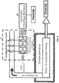
- the figure 1 represents an example of a power conversion system for a generator 100.
- the energy conversion system comprises the thermoacoustic system 20 comprising a heat exchanger 10, a regenerator 11 and a heat exchanger 30.
- the generator 100 comprises a drive system 40, an alternator 50 and a cooling system 60.
- the drive system 40 rotates a prime mover of the alternator 50, which converts mechanical energy into electrical energy to supply the load 51 with electricity.
- different components or fewer components may be included.
- the drive system 40 for mechanical-electrical conversion may be an internal combustion engine or a turbine.
- the turbine may comprise a rotor with symmetrical blades.
- a fluid in motion acts on the symmetrical blades to impart rotational energy to a rotor or shaft.
- combustion of fuel in the engine applies a force to one or more pistons that rotate a shaft.
- the rotational force rotates the alternator 50, which converts the mechanical energy into electrical energy to supply the load 51 with electricity.
- the drive system 40 produces an exhaust.
- the exhaust includes heat.
- the exhaust leaves the drive system 40 through an exhaust tube 41.
- temperatures for the exhaust may be 200 to 600 degrees Celsius.
- the temperature of the exhaust may depend on the fuel of the drive system 40. Examples of fuels include gasoline, kerosene, diesel fuel, liquefied petroleum gas (LPG) or gaseous fuels such as hydrogen , natural gas, biogas or other gas.
- LPG liquefied petroleum gas
- gaseous fuels such as hydrogen , natural gas, biogas or other gas.
- the regenerator 11 may be a thermal storage medium sandwiched between the heat exchanger 10 and the heat exchanger 30.
- the role of the heat exchangers is either to add heat to the working gas of the heat system. acoustic 20, which is the case of a hot heat exchanger such as the heat exchanger 10, or to remove heat from the working gas, which is the case of a cold heat exchanger such as the heat exchanger 30.
- thermo-acoustic system 20 thermo-acoustic cell
- the acoustic wave can be induced by the temperature gradient on the regenerator 11, which is due to a temperature difference between two heat exchangers 10 and 30.
- the acoustic wave can be amplified inside the regenerator 11.
- Heat exchangers 10 and 30 may be designed to add or remove heat to or from the working gas.
- the heat exchangers 10 and 30, through the cooling system 60, can remove heat from or cool the air that is admitted into the engine cylinders.
- the percentage at which heat is added or removed defines the efficiency of the heat exchanger.
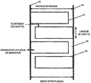
- the figure 2 represents a high efficiency heat exchanger, the "multichannel type 2" heat exchanger.
- the heat exchanger comprises two plates 16 which are separated by a space between plates to form the housing of the heat exchanger.
- the plates 16 support multiple plates 17.
- the working fluid oscillates inside the passage 19 formed by the spacing of the fins and the space between plates, as shown in FIG. figure 2 .
- the fins have a thickness in the page, which is not illustrated.
- the plates 16 may be of sufficient thickness to maintain a fluid to add or remove heat to / from the solid surface of the heat exchanger.
- the heat exchanger 10 transfers the heat in the exhaust to the thermoacoustic system 20.
- the thermoacoustic system 20 amplifies an acoustic wave from the energy in the heat.
- the amplified acoustic wave controls a heat pump to remove heat and cause refrigeration.
- the refrigeration or heat deficit is transferred by the heat exchanger 30 to the cooling system 60.
- the figure 3 represents the thermoacoustic system 20 comprising a heat-sound conversion system 21 (first thermo-acoustic device), a transfer medium 22 (for example, the regenerator 11), and a sound-cooling system 23 (second device thermo-acoustic).
- the heat / sound conversion system 21 can receive an input signal from an input acoustic source 24.
- the input signal can be a sound generated by an electroacoustic generator.
- the electroacoustic generator may be piezoelectric.
- An example of an input signal may have a low frequency signal (e.g., less than 100 Hertz).
- the heat / sound conversion system 21 may comprise a thermoacoustic cell and the sound / cold conversion system 23 may comprise another thermoacoustic cell.
- thermoacoustic system 20 comprising a first thermoacoustic cell 26a and a second thermoacoustic cell 26b.
- Each thermo-acoustic cell may comprise a heat exchanger on each side of a stack.
- Stacking is a solid material with pores that allow a gaseous fluid to oscillate while in contact with the solid material.
- the stack may be formed of multiple layers or rows of material spaced closely together.
- the material of the stack can be selected to have a low thermal conductivity and a heat capacity greater than the thermal capacity of the oscillating gas so that the stack temperature is stable. Examples of materials for stacking include various polymers, resins, ceramics and polyethylene terephthalate.
- thermo-acoustic system 20 Depending on the thermal diffusivity of the gas, the heat is diffused through the gas. In other words, the stack facilitates the oscillation of the gas from the sound to be transferred into heat. In a similar way, the introduction of heat into the thermo-acoustic cell increases the oscillation of the gas and amplifies the sound. Both principles are presented in the thermo-acoustic system 20.
- the heat from the exhaust is introduced into the first thermoacoustic cell 26a.
- the energy from the heat amplifies the small acoustic wave signal from the input acoustic source 24 to a larger acoustic wave signal propagating through the transfer medium 22 to the second thermoacoustic cell. 26b.
- Some heat can be lost by an optional heat exchanger downstream of the stack of the first thermoacoustic cell 26a.
- the larger acoustic wave signal propagates through the transfer medium 22.
- the transfer medium 22 may comprise a solid, a liquid or a gas.
- the medium of the transfer medium 22 is a noble gas such as helium.
- the acoustic wave signal may have a power on the order of 1-100 kilowatts (kW), for example 10 kW.
- the larger acoustic wave signal can be minimally attenuated by the transfer medium 22.
- the larger acoustic wave signal arrives at the second thermo-acoustic cell 26b, some heat can be lost initially at the optional heat exchanger upstream of the stack of the second thermo-acoustic cell 26b. .
- the larger acoustic wave signal oscillates the gas in the stack of the second thermo-acoustic cell 26b causing an inward heat flow. The heat flows from the refrigeration unit 26 into the second thermo-acoustic cell 26b.
- the optional resonator 25 defines a stationary wave for the thermoacoustic system 20.
- the resonance frequency of the resonator 25 depends on the dimensional characteristics of the tube or chamber.
- the frequency of the input acoustic source 24 and the material and the dimensions of the transfer medium 22 can be selected on the basis of the resonance frequency of the resonator 25.
- the temperature of the refrigeration unit 26 is lowered by the heat exchanger downstream of the stack of the second thermo-acoustic cell 26b.
- the heat is pumped out of the refrigeration unit 28 into the heat exchanger.
- the refrigeration unit 28 can cool water or other refrigerant for the drive system 40.
- the figure 5 is an example according to the invention of an engine and a thermo-acoustic system.
- the heat-sound conversion system 21 may comprise multiple thermoacoustic stages.
- Each thermo-acoustic stage may comprise a stack with adjacent heat exchangers, as described above.
- Each stage can have a reducing effect in terms of efficiency. For example, the efficiency of the first stage is greater than the yield of the second stage, and so on. However, the overall efficiency increases as the number of stages increases.
- each thermo-acoustic stage may be coupled to an exhaust heat exchanger or radiator which transfers heat from the gases or the exhaust pipe to the respective thermo-acoustic stage.
- the multiple thermo-acoustic stages can be housed in the same enclosure.
- An example of dimensions for the enclosure may be a cylinder having a height of 40 to 100 cm (for example, 60 cm) and a diameter of 40-100 cm (for example, 60 cm).
- An example of number of stages is three, as shown on the figure 5 .
- An example of pressure variation between the inlet on the first stage and the outlet of the final stage can be 40 bars.
- An example of power variation between the input on the first stage and the output of the final stage can be 20-40 kW.
- the inputs to the heat / sound conversion system 21 are the heat from the exhaust and an acoustic wave with a nominal power level.
- the output of the heat-sound conversion system 21 is the amplified acoustic wave transmitted to the sound-cooling conversion system 23.
- the sound-cooling conversion system although represented with a single stage, may also comprise multiple thermo-acoustic floors. Each thermo-acoustic stage may comprise a stack with adjacent heat exchangers, as described above.
- the enclosure of the sound / cold conversion system can be a cylinder of 20-40 cm high and having a diameter of 40-100 cm (for example, 60 cm).
- the output of the sound / cool conversion system 23 cools the inlet water for the internal combustion engine. In other words, the sound / cool conversion system 23 pumps the heat to itself, cooling the water or the inlet liquid through the heat exchanger or radiator.
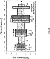
- the Figure 6A represents according to the invention an example of a three-stage thermo-acoustic system.
- Each of the first stage, the second stage and the third stage comprises a cold heat exchanger 10, a regenerator 11 and a hot heat exchanger 30.
- the thermoacoustic system can be enclosed in an insulated container.
- the stages are connected by a tube 31 which carries the working gas and the acoustic wave.
- the final heat exchanger 33 prevents heat leakage by heat exchange outside the insulated container.
- the three stages of the thermo-acoustic system can be selected to deliver the maximum net acoustic power.
- One, two, or four storeys or more can be used in the thermo-acoustic system.
- the performance of the three stages affects the performance of the drive system 40 and the generator 100.
- the temperature of the phase change material can not exceed a critical temperature T (eg 380 ° C). Heat can be extracted in the first and second recuperators while maintaining a high temperature in the first and second heat exchangers.
- the available heat is the heat that can be extracted from the flue gases without reaching the dew point temperature D (180 ° C).
- the properties of the exhaust gases are detailed in Table 2. ⁇ u> TABLE 2 ⁇ / u> Exhaust gas Exhaust temperature 495.00 ° C Dew temperature 180.00 ° C Density 0.45 kg / m3 Mass flow 0.21 kg / s Isobaric thermal capacity 1180.00 J / kg.K Heat available 78.06 kW
- the characteristics and dimensions that do not change for the three stages are shown in Table 2.
- the key parameter to obtain the target thermal power is the number of rows or layers in a stage that varies according to the exchange surface of heat. Reducing the surface area of the heat exchange surface increases the number of rows or layers in a floor.
- the depth of the heat exchange zone, compared to the length of the thermoacoustic system 20, the pressure loss and the flue velocity are used to select the floor design. There is a trade-off between the number of (floors / plates in a floor) and the different geometric and physical constraints. In one example, an area of 600 x 600 square millimeters (mm 2 ) with a single row for the first evaporator, six rows for the second and ten rows for the third. The total depth of three floors can be 600 mm.
- the Figure 6B is a bidirectional turbine geometry with acoustic flow movement 88.
- the turbine which can be a receiver system in fluid communication with any of the feedback systems described below (for example, Figure 7B , figure 9 ).
- the inertance represents a pressure difference in the fluid in order to vary a flow rate over time. Flexibility or compliance represents the resistance or ease with which the fluid is compressed. At the same time, the inertness and flexibility can produce acoustic oscillations similar to the electrical oscillations of an inductance and a capacitance in an AC electrical circuit.
- the Figure 7A represents according to the invention a thermoacoustic system 20 which is cylindrical.
- the first, second and third floors are arranged vertically. This has the advantage of being adapted for the use of standard components and to make it possible to produce pressure vessels, but also to reduce heat losses by conduction by reducing the thickness between the different parts of the thermo-acoustic line.
- the Figure 7B represents a thermoacoustic system 20 comprising the bi-directional turbine geometry 88 represented on the Figure 6B , a feedback system 91 and a turbine 95.
- the feedback system 91 may comprise a spiral tube for the recirculation of the working gas through the thermo-acoustic system 20.
- the turbine 95 may comprise a rotor with symmetrical blades which are surrounded by two sets of guide vanes. The shapes of the blades may be selected on the basis of the type of fluid or working gas or the density of the fluid or working gas.
- the feedback system 91 may be in communication with a receiver system such as the turbine 88 of the Figure 6B .
- the turbine can be bidirectional. Turbine performance (bidirectional) depends, among other parameters, on the density of the working fluid. Thermo-acoustic motors can operate at high average pressures up to 40 bar and this high gas density can increase turbine efficiency up to 85%. This makes bidirectional turbines an economical and flexible candidate for converting the generated acoustic power into electricity.
- the figure 8 represents another feedback system 91 or an acoustic feedback configuration.
- the feedback system may comprise an inlet tube 92, an outlet tube 93 and a feedback tube 94.
- the dimensions of the inlet tube 92 may be selected to correspond to the thermo-acoustic system 20.
- the dimensions of the tube Input 92 can be selected to correspond to the resonant frequency of the thermo-acoustic system 20.
- the outlet tube 93 is connected to the cooling system 60 of the generator 100 and to the feedback tube 94.
- the feedback tube 94 returns the gas to the inlet tube 92 for an additional traversing of the thermoacoustic system 20.
- An output 97 of the feedback system 91 may be in communication with a receiving system such as the turbine of the Figure 6B .
- the acoustic feedback configuration delivers 14 kW of electrical power, when the turbine has a yield of 80%.
- the system can extract 60 kW of thermal flux (77% of available thermal flux) with an overall thermal efficiency of 24%.
- the exergy yield of the system can be equal to 41% (Carnot is calculated according to the highest temperature (495 ° C) and the lower temperature (37 ° C) of the system).
- Table 3 shows the performance of the acoustic feedback configuration.
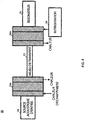
- the figure 9 according to the invention is another example of a motor and a thermo-acoustic system.
- the heat-sound conversion system 21 functions similarly to the foregoing descriptions, but instead of the sound-cooling conversion system 23, the system includes a mechano-electric conversion system 55 (for example, a turbine ).
- the mechanical-electrical conversion system 55 may correspond to the turbine 55 of the Figure 7B and / or at the turbine of the Figure 6B .
- the electro-electrical conversion system 55 may be combined with any of the embodiments described herein.
- the mechanical-electrical conversion system 55 may be a turbine such as a bidirectional turbine that generates electricity from the amplified acoustic signal.
- the pressure from the sound waves can turn a turbine, or oscillate a crankshaft and a piston, which turns a tree.
- the rotation can rotate a rotor and / or armature winding and generate electrical power.
- the electric power can be used as an additional component of the electrical power of the generator 100.
- electrical power can be converted to direct current, which can power an auxiliary system of the generator 100.
- An example of an auxiliary system is the control panel or a display for the generator 100.
- the electrical power can control an exciter or a field winding for the generator 100.
- the figure 10 according to the invention is another illustration of a drive system and a thermo-acoustic system.
- the system includes a secondary cooling source 61.
- the secondary cooling source 61 may be necessary because of the time that may be required. be necessary for the thermoacoustic system 20 to reach a stable state.
- the second cooling source 61 can supplement the primary cooling of the thermo-acoustic system when conditions are ineffective or additional cooling is required.
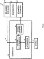
- the figure 11 is another illustration of an engine and a thermo-acoustic system.
- the system of figure 11 comprises a controller 70 and a switch 71.
- the controller 70 may include a thermometer or thermistor to monitor the temperature of the exhaust gas.
- the controller 70 may control the switch 71 to turn on or off the thermoacoustic system.
- the switch 71 may include a mechanical valve that variably controls the flow of exhaust from the engine 40 to the heat exchanger 10 or to the exhaust system 72.
- the switch 71 may include an electrical switch that turn on and off the sound source.
- the controller 71 can compare the temperature of the exhaust with one or more thresholds.
- the thermo-acoustic system can be used only in a predetermined temperature range.
- the amount of exhaust gas that can be diverted to the thermo-acoustic system may be a function of temperature.
- the drive system 40 may begin to run at a lower temperature, when the exhaust gas reaches the temperature threshold, the controller 70 and the switch 71 switch the exhaust of the exhaust system 72 to the heat exchanger 10, and finally to the thermo-acoustic system 20.
- the controller 70 can identify when the exhaust temperature becomes too high and may damage the heat exchanger 10 or the thermoacoustic system 20.
- the temperature is measured at a other portion of the generator 100 such as the alternator 50.
- the temperature of the alternator 50 can be calculated on the basis of a resistance measurement in the coils of the alternator 50 or calculated on the basis of an output or load on the alternator 50.
- the controller 71 is physically coupled to the generator 100.
- the controller 71 may be included in a control panel mounted on or near the generator 100.
- the controller 71 is remote from the generator 100 and the controller 71 remotely monitors the generator 100, the drive system 40, the thermo-acoustic system 20, the cooling system 60 or the exhaust.
- the generator 100 may be located in an installation (eg factory, ship) and the controller 71 is located in a control room or control facility.
- the generator 100 may comprise a device or a communication interface. Communication between the controller 71 and the generator may be wired or wireless.
- the communication interface of the generator 100 can be associated with an Internet protocol address and the communication is carried out over the Internet.
- the communication interface of the generator 100 and the controller 71 may be configured for communication using the protocol family known as Bluetooth®, the protocol family known as 802.11, cellular communication or other wireless communication.
- the control device 71 can also receive additional entries from one or more users.
- the user input may provide commands to fully or partially switch exhaust exhaust 72 on the thermo-acoustic system 20.
- the user input may specify a mode for operating the thermoacoustic system 20 or switch 71.
- the mode may be a performance mode that optimizes the degree of channeling of the exhaust to the thermo-acoustic system 20.
- the mode can be a mode of performance which selects the most effective times for switching the exhaust on the thermo-acoustic system 20.
- the controller 71 may locally monitor or remotely monitor external input parameters for partial or total switching of the evacuation 72 to the thermo-acoustic system 20.
- Input parameters external may include properties of a distribution service system connected to the generator 100.
- the distribution service system properties may include whether or not the distribution service provides electricity to a system including the generator 100, a degree of application of electricity, a cost of electricity at a present time, a power factor at the present time or other properties.
- Controls for the controller 71 may also be received directly from the distribution service system. The controller 71 may determine whether to connect the thermoacoustic system 20 based on the properties of the distribution service.
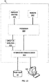
- the figure 12 represents according to the invention multiple generating groups 100A-C.
- Generator groups 100A-C may be connected to a common bus to deliver power to a common load.
- Generator groups 100A-C can be synchronized or paralleled.
- the generator sets 100A-C can share a thermo-acoustic system.
- the exhaust lines of generator sets 100A-C may be physically connected to heat exchanger 10, thermoacoustic system 20 and a cooling system 160 described above.
- the cooling system 160 can cool one, some or all of the engines of the generator sets 100A-C.
- different combinations of generator sets 100A-C are connected by controller 70 and switch 71 as a function of temperature.
- the controller 70 may selectively control which generator sets 100A-C are cooled by the cooling system 160.
- Additional components of the drive system 40 may include a manifold, one or more cylinders, a fuel supply, a cruise control, a lubrication system and a starter.
- the switch 71 can turn on and off the input sound source 25 to coincide with the exhaust gas which are diverted to the thermo-acoustic system.
- the controller 70 can selectively connect and disconnect the thermoacoustic system 20 from generator sets 100A-C at different degrees depending on one or more inputs including, but not limited to remote commands, distribution service properties, user commands, and sensor measurements.
- the controller 70 and a switching network can independently connect and disconnect the generator sets 100A-C.
- one or more of the generator sets 100A-C may be connected to the thermoacoustic system 20 at the same time that one or more other generator sets 100A-C are not connected.
- the connection model can be based on individual measurements made by the generator sets 100A-C or specific commands received for individual generator sets.
- the thermoacoustic system 20 can be connected to one of the generator groups 100A-C which can benefit the most from the thermo-acoustic system 20.
- the switching network can connect only the generator group with the highest exhaust temperature.
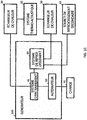
- the controller 70 may include a processor 300, an input device 305, a communication interface 303, a memory 302 and a display.
- the display may be integrated with the computing device or provided by a workstation 309.
- the database 307 may include parameters for the thermoacoustic system 20. Additional, different or fewer components may be included.
- the detection circuit 311 may be a thermometer or a thermistor as explained above.
- the processor 300 can control the switch 71 or another aspect of the thermoacoustic system 20 depending on the output of the detection circuit 311.
- Other types of sensors for the detection circuit 311 are gas detectors, movement, temperature sensors, pressure sensors and internal sensors of the motor. Examples of gas detectors may include one or more of an oxygen sensor, a carbon dioxide detector, a carbon monoxide detector or an emission detector.
- the processor 300 can control the switch 71 or the thermoacoustic system 20 based on the output of any of these sensors.
- the processor 300 may include a general processor, a digital signal processor, an application specific integrated circuit (ASIC), a user programmable gate array (FPGA), an analog circuit, a digital circuit, combinations of these or any other processor currently known or developed later.
- the memory 302 may be a volatile memory or a non-volatile memory.
- the memories may include one or more of a read only memory (ROM), random access memory (RAM), flash memory, electrically erasable programmable read only memory (EEPROM), or other type of memory.
- the memory 201 may be removable relative to the control device 302 and the memory 15 may be removable relative to the motor, such as a secure digital memory card (SD).
- SD secure digital memory card
- the communication interface 303 may comprise a physical interface, an electrical interface and / or a data interface.
- the communication interface 303 provides wireless and / or cable communications in any format currently known or further developed.
- the communication interface 303 may include any usable connection.
- An exploitable connection may be one in which signals, physical communications, and / or logical communications may be transmitted and / or received.
- An exploitable connection may include a physical interface, an electrical interface, and / or a data interface.
- the communication interface 303 may be connected to a network.
- the network may include wired networks (eg, Ethernet), wireless networks, or combinations thereof.
- the wireless network can be a cellular telephone network, an 802.11, 802.16, 802.20 or WiMax® network.
- the network may be a public network, such as the Internet, a private network, such as an intranet, or a combination thereof, and may use a variety of networking protocols now available or further developed including, but without limitation, networking protocols based on TCP / IP.
- non-transitory computer readable medium which may be a single medium or multiple media, such as a centralized or distributed database and / or associated caches and servers that store one or more sets of instructions.
- computer-readable non-transitory media shall also include any medium, except a signal in itself, that is capable of storing, encoding, or transporting a set of instructions for execution by a processor or that causes to any computer system any one or more of the methods or operations described herein.
- the computer readable medium may comprise a semiconductor memory such as a memory card or other container which houses one or more non-volatile read-only memories.
- the computer readable medium may be a RAM or other volatile rewritable memory.
- the computer-readable medium may comprise a magneto-optical medium or an optical medium, such as a disk or tapes or other storage device for capturing carrier wave signals such as a signal communicated on a medium of transmission.
- a digital file attached to an email or other archive or set of autonomous information archives may be considered a distribution medium that is a tangible storage medium. Therefore, the description is considered to include any one or more of a computer readable medium or a distribution medium and other equivalent media and successors upon which data or instructions may be stored.
- the computer readable medium may be non-transient, which includes all tangible computer readable media.
- dedicated hardware implementations such as application-specific integrated circuits, programmable logic networks, and other hardware devices, may be constructed to implement one or more of the methods described herein.
- Applications that may include the apparatus and systems of various embodiments may generally include a variety of electronic and computer systems.
- One or more embodiments described herein may implement functions using at least two specific interconnected hardware modules or devices with associated control and data signals that may be communicated between and across the modules, or as portions of an integrated circuit specific to the application. As a result, this system covers software, firmware and hardware implementations.
Landscapes
- Engineering & Computer Science (AREA)
- Chemical & Material Sciences (AREA)
- Combustion & Propulsion (AREA)
- Mechanical Engineering (AREA)
- General Engineering & Computer Science (AREA)
- Connection Of Motors, Electrical Generators, Mechanical Devices, And The Like (AREA)
Priority Applications (1)
| Application Number | Priority Date | Filing Date | Title |
|---|---|---|---|
| PL15199996T PL3034826T3 (pl) | 2014-12-17 | 2015-12-15 | Źródło chłodzenia wykorzystujące energię akustyczną |
Applications Claiming Priority (2)
| Application Number | Priority Date | Filing Date | Title |
|---|---|---|---|
| FR1462661A FR3030701A1 (pl) | 2014-12-17 | 2014-12-17 | |
| FR1557309A FR3030644B1 (fr) | 2014-12-17 | 2015-07-30 | Source de refroidissement par energie acoustique |
Publications (2)
| Publication Number | Publication Date |
|---|---|
| EP3034826A1 EP3034826A1 (fr) | 2016-06-22 |
| EP3034826B1 true EP3034826B1 (fr) | 2019-07-24 |
Family
ID=54834763
Family Applications (1)
| Application Number | Title | Priority Date | Filing Date |
|---|---|---|---|
| EP15199996.8A Active EP3034826B1 (fr) | 2014-12-17 | 2015-12-15 | Source de refroidissement par énergie acoustique |
Country Status (2)
| Country | Link |
|---|---|
| EP (1) | EP3034826B1 (pl) |
| PL (1) | PL3034826T3 (pl) |
Family Cites Families (4)
| Publication number | Priority date | Publication date | Assignee | Title |
|---|---|---|---|---|
| JP2005233485A (ja) * | 2004-02-18 | 2005-09-02 | Toyota Motor Corp | 内燃機関の冷却装置 |
| JP4652822B2 (ja) * | 2005-01-07 | 2011-03-16 | 学校法人同志社 | 熱音響装置 |
| CN101608847B (zh) * | 2008-06-18 | 2011-04-13 | 深圳市中科力函热声技术工程研究中心有限公司 | 内燃机尾气余热驱动的热声制冷系统 |
| JP5548513B2 (ja) * | 2010-04-23 | 2014-07-16 | 本田技研工業株式会社 | 熱音響機関 |
-
2015
- 2015-12-15 PL PL15199996T patent/PL3034826T3/pl unknown
- 2015-12-15 EP EP15199996.8A patent/EP3034826B1/fr active Active
Non-Patent Citations (1)
| Title |
|---|
| None * |
Also Published As
| Publication number | Publication date |
|---|---|
| PL3034826T3 (pl) | 2020-02-28 |
| EP3034826A1 (fr) | 2016-06-22 |
Similar Documents
| Publication | Publication Date | Title |
|---|---|---|
| FR3030644A1 (fr) | Source de refroidissement par energie acoustique | |
| EP2534357B1 (fr) | Machine thermoacoustique a boucle de retroaction electrique | |
| CA2639217A1 (fr) | Generation d'electricite dans une turbomachine | |
| FR2935737A1 (fr) | Dispositif de cogeneration amelioree | |
| FR3016025A1 (fr) | Combinaison d'une unite de stockage d'energie par air comprime et d'une centrale thermique | |
| FR2998265A1 (fr) | Procede et systeme de conditionnement d'air pour aeronef | |
| FR3052440A1 (fr) | Integration d'un materiau a changement de phase pour limiter la temperature du carburant a partir d'un module electronique. | |
| EP3034826B1 (fr) | Source de refroidissement par énergie acoustique | |
| FR2971552A1 (fr) | Machine thermoacoustique a boucle de retroaction electrique | |
| CA3122306A1 (fr) | Poste de detente d'un gaz et de compression d'un fluide | |
| Di Bella | Gas turbine engine exhaust waste heat recovery using supercritical CO2 Brayton cycle with thermoelectric generator technology | |
| WO2014080130A1 (fr) | Groupe de conversion d'une energie thermique en une energie hydraulique | |
| FR3053401A1 (fr) | Systeme comprenant des moyens de refroidissement de machine thermique | |
| WO2016131917A1 (fr) | Moteur thermoacoustique | |
| EP3099919B1 (fr) | Moteur à combustion externe | |
| FR3132736A1 (fr) | Turbomachine de chauffage pour un système de conditionnement de carburant configuré pour alimenter un turbomoteur d’aéronef à partir de carburant issu d’un réservoir cryogénique | |
| CA3142977A1 (fr) | Dispositif thermodynamique haut rendement hybride solaire et couple hydrogene-oxygene produisant une pluralite d'energies | |
| CA3173293A1 (fr) | Systeme de compression thermique d'un gaz | |
| WO2023222971A1 (fr) | Système de génération de froid et de fourniture d'énergie électrique à partir de l'eau de mer et du soleil | |
| EP4453483A1 (fr) | Modulation de puissance acoustique dans une machine thermoacoustique | |
| WO2023099185A1 (fr) | Machine thermoacoustique à modulation de déphasage | |
| FR3074234A1 (fr) | Systeme de refroidissement | |
| Mollard et al. | SAGA, premier sous marin industriel autonome | |
| FR2958687A1 (fr) | Moteur thermique sans carburant adaptable notamment a l'automobile et au nucleaire | |
| FR3070479A1 (fr) | Systeme thermo-acoustique |
Legal Events
| Date | Code | Title | Description |
|---|---|---|---|
| PUAI | Public reference made under article 153(3) epc to a published international application that has entered the european phase |
Free format text: ORIGINAL CODE: 0009012 |
|
| AK | Designated contracting states |
Kind code of ref document: A1 Designated state(s): AL AT BE BG CH CY CZ DE DK EE ES FI FR GB GR HR HU IE IS IT LI LT LU LV MC MK MT NL NO PL PT RO RS SE SI SK SM TR |
|
| AX | Request for extension of the european patent |
Extension state: BA ME |
|
| STAA | Information on the status of an ep patent application or granted ep patent |
Free format text: STATUS: REQUEST FOR EXAMINATION WAS MADE |
|
| 17P | Request for examination filed |
Effective date: 20161219 |
|
| RBV | Designated contracting states (corrected) |
Designated state(s): AL AT BE BG CH CY CZ DE DK EE ES FI FR GB GR HR HU IE IS IT LI LT LU LV MC MK MT NL NO PL PT RO RS SE SI SK SM TR |
|
| STAA | Information on the status of an ep patent application or granted ep patent |
Free format text: STATUS: EXAMINATION IS IN PROGRESS |
|
| 17Q | First examination report despatched |
Effective date: 20170712 |
|
| GRAP | Despatch of communication of intention to grant a patent |
Free format text: ORIGINAL CODE: EPIDOSNIGR1 |
|
| STAA | Information on the status of an ep patent application or granted ep patent |
Free format text: STATUS: GRANT OF PATENT IS INTENDED |
|
| INTG | Intention to grant announced |
Effective date: 20190218 |
|
| GRAS | Grant fee paid |
Free format text: ORIGINAL CODE: EPIDOSNIGR3 |
|
| GRAA | (expected) grant |
Free format text: ORIGINAL CODE: 0009210 |
|
| STAA | Information on the status of an ep patent application or granted ep patent |
Free format text: STATUS: THE PATENT HAS BEEN GRANTED |
|
| AK | Designated contracting states |
Kind code of ref document: B1 Designated state(s): AL AT BE BG CH CY CZ DE DK EE ES FI FR GB GR HR HU IE IS IT LI LT LU LV MC MK MT NL NO PL PT RO RS SE SI SK SM TR |
|
| REG | Reference to a national code |
Ref country code: GB Ref legal event code: FG4D Free format text: NOT ENGLISH |
|
| REG | Reference to a national code |
Ref country code: CH Ref legal event code: EP |
|
| REG | Reference to a national code |
Ref country code: DE Ref legal event code: R096 Ref document number: 602015034208 Country of ref document: DE |
|
| REG | Reference to a national code |
Ref country code: AT Ref legal event code: REF Ref document number: 1158461 Country of ref document: AT Kind code of ref document: T Effective date: 20190815 |
|
| REG | Reference to a national code |
Ref country code: IE Ref legal event code: FG4D Free format text: LANGUAGE OF EP DOCUMENT: FRENCH |
|
| REG | Reference to a national code |
Ref country code: NL Ref legal event code: FP |
|
| REG | Reference to a national code |
Ref country code: LT Ref legal event code: MG4D |
|
| REG | Reference to a national code |
Ref country code: AT Ref legal event code: MK05 Ref document number: 1158461 Country of ref document: AT Kind code of ref document: T Effective date: 20190724 |
|
| PG25 | Lapsed in a contracting state [announced via postgrant information from national office to epo] |
Ref country code: FI Free format text: LAPSE BECAUSE OF FAILURE TO SUBMIT A TRANSLATION OF THE DESCRIPTION OR TO PAY THE FEE WITHIN THE PRESCRIBED TIME-LIMIT Effective date: 20190724 Ref country code: AT Free format text: LAPSE BECAUSE OF FAILURE TO SUBMIT A TRANSLATION OF THE DESCRIPTION OR TO PAY THE FEE WITHIN THE PRESCRIBED TIME-LIMIT Effective date: 20190724 Ref country code: LT Free format text: LAPSE BECAUSE OF FAILURE TO SUBMIT A TRANSLATION OF THE DESCRIPTION OR TO PAY THE FEE WITHIN THE PRESCRIBED TIME-LIMIT Effective date: 20190724 Ref country code: PT Free format text: LAPSE BECAUSE OF FAILURE TO SUBMIT A TRANSLATION OF THE DESCRIPTION OR TO PAY THE FEE WITHIN THE PRESCRIBED TIME-LIMIT Effective date: 20191125 Ref country code: BG Free format text: LAPSE BECAUSE OF FAILURE TO SUBMIT A TRANSLATION OF THE DESCRIPTION OR TO PAY THE FEE WITHIN THE PRESCRIBED TIME-LIMIT Effective date: 20191024 Ref country code: NO Free format text: LAPSE BECAUSE OF FAILURE TO SUBMIT A TRANSLATION OF THE DESCRIPTION OR TO PAY THE FEE WITHIN THE PRESCRIBED TIME-LIMIT Effective date: 20191024 Ref country code: HR Free format text: LAPSE BECAUSE OF FAILURE TO SUBMIT A TRANSLATION OF THE DESCRIPTION OR TO PAY THE FEE WITHIN THE PRESCRIBED TIME-LIMIT Effective date: 20190724 Ref country code: SE Free format text: LAPSE BECAUSE OF FAILURE TO SUBMIT A TRANSLATION OF THE DESCRIPTION OR TO PAY THE FEE WITHIN THE PRESCRIBED TIME-LIMIT Effective date: 20190724 |
|
| PG25 | Lapsed in a contracting state [announced via postgrant information from national office to epo] |
Ref country code: RS Free format text: LAPSE BECAUSE OF FAILURE TO SUBMIT A TRANSLATION OF THE DESCRIPTION OR TO PAY THE FEE WITHIN THE PRESCRIBED TIME-LIMIT Effective date: 20190724 Ref country code: IS Free format text: LAPSE BECAUSE OF FAILURE TO SUBMIT A TRANSLATION OF THE DESCRIPTION OR TO PAY THE FEE WITHIN THE PRESCRIBED TIME-LIMIT Effective date: 20191124 Ref country code: AL Free format text: LAPSE BECAUSE OF FAILURE TO SUBMIT A TRANSLATION OF THE DESCRIPTION OR TO PAY THE FEE WITHIN THE PRESCRIBED TIME-LIMIT Effective date: 20190724 Ref country code: LV Free format text: LAPSE BECAUSE OF FAILURE TO SUBMIT A TRANSLATION OF THE DESCRIPTION OR TO PAY THE FEE WITHIN THE PRESCRIBED TIME-LIMIT Effective date: 20190724 |
|
| REG | Reference to a national code |
Ref country code: GR Ref legal event code: EP Ref document number: 20190403252 Country of ref document: GR Effective date: 20200213 |
|
| REG | Reference to a national code |
Ref country code: ES Ref legal event code: FG2A Ref document number: 2751749 Country of ref document: ES Kind code of ref document: T3 Effective date: 20200401 |
|
| PG25 | Lapsed in a contracting state [announced via postgrant information from national office to epo] |
Ref country code: EE Free format text: LAPSE BECAUSE OF FAILURE TO SUBMIT A TRANSLATION OF THE DESCRIPTION OR TO PAY THE FEE WITHIN THE PRESCRIBED TIME-LIMIT Effective date: 20190724 Ref country code: DK Free format text: LAPSE BECAUSE OF FAILURE TO SUBMIT A TRANSLATION OF THE DESCRIPTION OR TO PAY THE FEE WITHIN THE PRESCRIBED TIME-LIMIT Effective date: 20190724 Ref country code: RO Free format text: LAPSE BECAUSE OF FAILURE TO SUBMIT A TRANSLATION OF THE DESCRIPTION OR TO PAY THE FEE WITHIN THE PRESCRIBED TIME-LIMIT Effective date: 20190724 |
|
| RAP2 | Party data changed (patent owner data changed or rights of a patent transferred) |
Owner name: HEKYOM |
|
| RAP2 | Party data changed (patent owner data changed or rights of a patent transferred) |
Owner name: EQUIUM GROUPE |
|
| PG25 | Lapsed in a contracting state [announced via postgrant information from national office to epo] |
Ref country code: SK Free format text: LAPSE BECAUSE OF FAILURE TO SUBMIT A TRANSLATION OF THE DESCRIPTION OR TO PAY THE FEE WITHIN THE PRESCRIBED TIME-LIMIT Effective date: 20190724 Ref country code: IS Free format text: LAPSE BECAUSE OF FAILURE TO SUBMIT A TRANSLATION OF THE DESCRIPTION OR TO PAY THE FEE WITHIN THE PRESCRIBED TIME-LIMIT Effective date: 20200224 Ref country code: CZ Free format text: LAPSE BECAUSE OF FAILURE TO SUBMIT A TRANSLATION OF THE DESCRIPTION OR TO PAY THE FEE WITHIN THE PRESCRIBED TIME-LIMIT Effective date: 20190724 Ref country code: SM Free format text: LAPSE BECAUSE OF FAILURE TO SUBMIT A TRANSLATION OF THE DESCRIPTION OR TO PAY THE FEE WITHIN THE PRESCRIBED TIME-LIMIT Effective date: 20190724 |
|
| REG | Reference to a national code |
Ref country code: DE Ref legal event code: R097 Ref document number: 602015034208 Country of ref document: DE |
|
| REG | Reference to a national code |
Ref country code: DE Ref legal event code: R082 Ref document number: 602015034208 Country of ref document: DE Representative=s name: DENNEMEYER & ASSOCIATES S.A., LU Ref country code: DE Ref legal event code: R081 Ref document number: 602015034208 Country of ref document: DE Owner name: EQUIUM GROUPE, FR Free format text: FORMER OWNER: HEKYOM, ORSAY, FR Ref country code: DE Ref legal event code: R081 Ref document number: 602015034208 Country of ref document: DE Owner name: EQUIUM GROUPE, FR Free format text: FORMER OWNER: SDMO INDUSTRIES, BREST, FR |
|
| REG | Reference to a national code |
Ref country code: NL Ref legal event code: PD Owner name: EQUIUM GROUPE; FR Free format text: DETAILS ASSIGNMENT: CHANGE OF OWNER(S), ASSIGNMENT; FORMER OWNER NAME: SDMO INDUSTRIES Effective date: 20200611 |
|
| PLBE | No opposition filed within time limit |
Free format text: ORIGINAL CODE: 0009261 |
|
| STAA | Information on the status of an ep patent application or granted ep patent |
Free format text: STATUS: NO OPPOSITION FILED WITHIN TIME LIMIT |
|
| REG | Reference to a national code |
Ref country code: GB Ref legal event code: 732E Free format text: REGISTERED BETWEEN 20200702 AND 20200708 |
|
| PG2D | Information on lapse in contracting state deleted |
Ref country code: IS |
|
| REG | Reference to a national code |
Ref country code: CH Ref legal event code: PL |
|
| 26N | No opposition filed |
Effective date: 20200603 |
|
| REG | Reference to a national code |
Ref country code: BE Ref legal event code: MM Effective date: 20191231 |
|
| PG25 | Lapsed in a contracting state [announced via postgrant information from national office to epo] |
Ref country code: SI Free format text: LAPSE BECAUSE OF FAILURE TO SUBMIT A TRANSLATION OF THE DESCRIPTION OR TO PAY THE FEE WITHIN THE PRESCRIBED TIME-LIMIT Effective date: 20190724 Ref country code: MC Free format text: LAPSE BECAUSE OF FAILURE TO SUBMIT A TRANSLATION OF THE DESCRIPTION OR TO PAY THE FEE WITHIN THE PRESCRIBED TIME-LIMIT Effective date: 20190724 |
|
| PG25 | Lapsed in a contracting state [announced via postgrant information from national office to epo] |
Ref country code: LU Free format text: LAPSE BECAUSE OF NON-PAYMENT OF DUE FEES Effective date: 20191215 Ref country code: IE Free format text: LAPSE BECAUSE OF NON-PAYMENT OF DUE FEES Effective date: 20191215 |
|
| PG25 | Lapsed in a contracting state [announced via postgrant information from national office to epo] |
Ref country code: BE Free format text: LAPSE BECAUSE OF NON-PAYMENT OF DUE FEES Effective date: 20191231 Ref country code: LI Free format text: LAPSE BECAUSE OF NON-PAYMENT OF DUE FEES Effective date: 20191231 Ref country code: CH Free format text: LAPSE BECAUSE OF NON-PAYMENT OF DUE FEES Effective date: 20191231 |
|
| PG25 | Lapsed in a contracting state [announced via postgrant information from national office to epo] |
Ref country code: CY Free format text: LAPSE BECAUSE OF FAILURE TO SUBMIT A TRANSLATION OF THE DESCRIPTION OR TO PAY THE FEE WITHIN THE PRESCRIBED TIME-LIMIT Effective date: 20190724 |
|
| PG25 | Lapsed in a contracting state [announced via postgrant information from national office to epo] |
Ref country code: MT Free format text: LAPSE BECAUSE OF FAILURE TO SUBMIT A TRANSLATION OF THE DESCRIPTION OR TO PAY THE FEE WITHIN THE PRESCRIBED TIME-LIMIT Effective date: 20190724 Ref country code: HU Free format text: LAPSE BECAUSE OF FAILURE TO SUBMIT A TRANSLATION OF THE DESCRIPTION OR TO PAY THE FEE WITHIN THE PRESCRIBED TIME-LIMIT; INVALID AB INITIO Effective date: 20151215 |
|
| PG25 | Lapsed in a contracting state [announced via postgrant information from national office to epo] |
Ref country code: MK Free format text: LAPSE BECAUSE OF FAILURE TO SUBMIT A TRANSLATION OF THE DESCRIPTION OR TO PAY THE FEE WITHIN THE PRESCRIBED TIME-LIMIT Effective date: 20190724 |
|
| PGFP | Annual fee paid to national office [announced via postgrant information from national office to epo] |
Ref country code: GB Payment date: 20221223 Year of fee payment: 8 |
|
| PGFP | Annual fee paid to national office [announced via postgrant information from national office to epo] |
Ref country code: PL Payment date: 20221206 Year of fee payment: 8 |
|
| PGFP | Annual fee paid to national office [announced via postgrant information from national office to epo] |
Ref country code: IT Payment date: 20221228 Year of fee payment: 8 |
|
| GBPC | Gb: european patent ceased through non-payment of renewal fee |
Effective date: 20231215 |
|
| PG25 | Lapsed in a contracting state [announced via postgrant information from national office to epo] |
Ref country code: GB Free format text: LAPSE BECAUSE OF NON-PAYMENT OF DUE FEES Effective date: 20231215 |
|
| PG25 | Lapsed in a contracting state [announced via postgrant information from national office to epo] |
Ref country code: GB Free format text: LAPSE BECAUSE OF NON-PAYMENT OF DUE FEES Effective date: 20231215 |
|
| PGFP | Annual fee paid to national office [announced via postgrant information from national office to epo] |
Ref country code: NL Payment date: 20241224 Year of fee payment: 10 Ref country code: GR Payment date: 20241227 Year of fee payment: 10 |
|
| PGFP | Annual fee paid to national office [announced via postgrant information from national office to epo] |
Ref country code: FR Payment date: 20241219 Year of fee payment: 10 |
|
| PGFP | Annual fee paid to national office [announced via postgrant information from national office to epo] |
Ref country code: DE Payment date: 20250127 Year of fee payment: 10 |
|
| PGFP | Annual fee paid to national office [announced via postgrant information from national office to epo] |
Ref country code: ES Payment date: 20250225 Year of fee payment: 10 |
|
| PG25 | Lapsed in a contracting state [announced via postgrant information from national office to epo] |
Ref country code: PL Free format text: LAPSE BECAUSE OF NON-PAYMENT OF DUE FEES Effective date: 20231215 |
|
| PGFP | Annual fee paid to national office [announced via postgrant information from national office to epo] |
Ref country code: TR Payment date: 20241213 Year of fee payment: 10 |
|
| REG | Reference to a national code |
Ref country code: DE Ref legal event code: R082 Ref document number: 602015034208 Country of ref document: DE Representative=s name: DENNEMEYER & ASSOCIATES RECHTSANWALTSGESELLSCH, DE |
|
| PG25 | Lapsed in a contracting state [announced via postgrant information from national office to epo] |
Ref country code: IT Free format text: LAPSE BECAUSE OF NON-PAYMENT OF DUE FEES Effective date: 20231215 |