EP3034420A1 - A method of docking a modular labelling group to a labelling machine, and a modular labelling group - Google Patents
A method of docking a modular labelling group to a labelling machine, and a modular labelling group Download PDFInfo
- Publication number
- EP3034420A1 EP3034420A1 EP14198075.5A EP14198075A EP3034420A1 EP 3034420 A1 EP3034420 A1 EP 3034420A1 EP 14198075 A EP14198075 A EP 14198075A EP 3034420 A1 EP3034420 A1 EP 3034420A1
- Authority
- EP
- European Patent Office
- Prior art keywords
- modular
- operative group
- group
- floor
- modular operative
- Prior art date
- Legal status (The legal status is an assumption and is not a legal conclusion. Google has not performed a legal analysis and makes no representation as to the accuracy of the status listed.)
- Withdrawn
Links
Images


Classifications
-
- B—PERFORMING OPERATIONS; TRANSPORTING
- B65—CONVEYING; PACKING; STORING; HANDLING THIN OR FILAMENTARY MATERIAL
- B65C—LABELLING OR TAGGING MACHINES, APPARATUS, OR PROCESSES
- B65C9/00—Details of labelling machines or apparatus
- B65C9/0062—Interchangeable modules, e.g. applicator heads with label magazines and glue rollers
Definitions
- the present invention relates to method of docking a modular operative group to a carousel of an article-handling machine for carrying out an operation on a plurality of articles, and to a modular operative group.
- the article-handling machine is a labelling machine for applying a plurality of labels onto respective containers filled with a pourable food product.
- Labelling machines are known, which substantially comprise:
- Labelling machine is known as "roll-feed", in which each modular labelling group substantially comprises, each,:
- a conventional transfer drum is rotatable about an axis, comprises an outer surface which receives a succession of cut labels and covered with glue, and releases those labels at respective application station after rotation about its own axis of a certain angle.
- the transfer drum conveys the labels tangentially to the outer surface of the articles to be labelled, at the application station.
- the frame supports the shaft, the unwinding rollers, the transfer drum and the gluing drum.
- the docking operation is particularly difficult to be carried out, especially when the labelling group is particularly heavy.
- the modular operative group is not a labelling group, but is adapted to carry out a different operation on the articles, e.g. a blowing, rinsing, filling, capping, operation.
- EP-B-1,493,671 discloses a modular labelling group, which comprises a pair of vertically retractable wheels.
- the present invention also relates to a modular operative group for carrying out an operation on a plurality of articles, as claimed in claim 13.
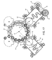
- Number 1 in Figures 17 and 18 indicates as a whole a labelling machine for applying labels (not-shown) to respective articles 11 (only schematically shown in Figures 17 and 18 ), containers for pourable food product in the embodiment shown.
- labelling machine 1 is a so-called "roll-fed” labelling machine.
- Labelling machine 1 substantially comprises ( Figure 1 ) :
- Carousel 3 comprises a radially outer periphery 14 with respect to axis A and a plurality of pair of docking elements 5 for docking respective labelling groups 4 to carousel 3
- Docking elements 5 are arranged radially inner with respect to periphery 14.
- Labelling group 4 is in the embodiment shown a so-called "roll-fed” labelling group and substantially comprises ( Figures 17 and 18 ), in the embodiment shown,:
- Labelling group 4 comprises ( Figures 1 to 8 ) a frame 10 (indicated only in Figure 17 ), which supports shafts 6, rollers 16, glue roller 12 and transfer element 13.
- Frame 10 comprises:
- Frame 10 further comprises a pair of docking elements 40.
- docking elements 40 protrude from wall 20 on the opposite side of walls 21.
- floor 24 lies on a plane substantially orthogonal to axis A.
- labelling group 4 can be set in:
- walls 20, 21; 22, 23 are inclined with respect to direction G, when labelling group 4 is in the initial approach position. Furthermore, walls 20, 21; 22 are respectively orthogonal and parallel to direction G, when labelling group 4 is in the fully docked position.
- labelling group 4 is rotatable about an axis H between a first angular position, in which it is in the pre-docked position and in the fully docked position ( Figures 3 to 6 ) and a second angular position, in which it is in the docked and levelled position ( Figures 7 and 8 ).
- Axis H is in the embodiment shown, parallel to axis A.
- labelling group 4 is set:
- labelling group 4 rotates tangentially with respect to axis H, from the respective first angular position ( Figures 3 and 4 ) to the respective angular second position ( Figures 5 and 6 ) reached in the fully docked position.
- Docking elements 5 comprise respective seats 48.
- Seats 48 are, in the embodiments shown, shaped as conical surfaces having respective axes I parallel to axes A, H.
- one seat 48 is conical around relative axis I and the other seat 48 is V-shaped around relative axis I.
- Seats 48 are open towards bodies 49 and taper on the opposite side of bodies 49, proceeding parallel to axis H.
- Docking elements 40 are shaped as partially spherical bodies 49 having respective axes J.
- Bodies 49 are free to tilt inside seats 48 about respective axes I, when respective axes I, J are inclined with respect to one another.
- labelling group 4 is set in the pre-docked position.
- Bodies 49 are blocked inside seats 48, when respective axes I coincide with corresponding axes J.
- labelling group 4 When bodies 49 are blocked inside seats 48, labelling group 4 is set in the fully docked position and then is straightened into the docked and levelled position.
- labelling group 4 tangentially rotates about axis H from the first angular position towards the second angular position.
- This tangential rotation of labelling group 4 is preferably caused by a torque about axis H generated by the weight of labelling group 4.
- a not-shown actuator for cause or ease the rotation of labelling group 4 tangentially about axis H from the pre-docked position to the fully docked position.
- labelling group 4 comprises a pair of support elements 26, which rest on floor 24 when labelling group 4 is in the docked and levelled posiiton, so as to support labelling group 4 ( Figures 7 and 8 ).
- support elements 26 comprise respective pedestals 27.
- Pedestals 27 are selectively movable along respective axes B between:
- pedestals 27 are arranged in respective withdrawn and raised position, when labelling group 4 is set in the initial approach position or in the pre-docking position.
- Pedestals 27 are arranged in the respective extended and lowered position, when labelling group 4 is set in the docked and levelled position.
- Labelling group 4 further comprises actuators 28 for selectively moving respective pedestals 27 parallel to respective axes B between respective extended positions and withdrawn positions.
- Pedestals 27 comprise, each,:
- surface 31 is a spherically mounted pivot plate, which is free to rotate for adjusting its position with respect to the irregularities and inclinations of floor 24
- Pedestals 27 and actuators 28 protrude from wall 21 on the opposite side of wall 20.
- Labelling group 4 further comprises:
- Wheels 35 are interposed between wall 20 and wheels 45.
- Wheels 35 are interposed between wheels 45 and wall 21.
- Wheels 35 are movable along an axis C parallel to axis B between:
- wheels 35 are arranged in respective extended and lowered positions, when labelling group 4 is arranged in the initial approach position.
- Wheels 35 are arranged in the respective withdrawn and raised positions, when labelling group 4 is arranged in the pre-docked position, in the fully docked position and in the docked and levelled position.
- Labelling group 4 further comprises a pair of actuators 36 for selectively moving respective wheels 35 parallel to respective axes C between respective extended positions and withdrawn positions.
- labelling group 4 comprises, for each wheel 35,:
- Housings 37, relative stems 38 and relative wheels 35 project from respective walls 22 on respective lateral sides of frame 10.
- Wheels 45 are movable along respective axis D parallel to axes B, C between:
- wheels 45 are arranged in respective extended and raised positions, when labelling group 4 is arranged in the initial approach position, in the pre-docked position or in the fully docked position.
- Wheels 45 are also arranged in respective withdrawn and lowered positions, when labelling group 4 is arranged in the docked and levelled position.
- wheels 45 are movable about axis D between:
- wheels 45 are arranged in respective first angular positions, when labelling group 4 is arranged in the initial approach position, in the pre-docked position and in the docked and levelled position ( Figures 1 to 4 , 7 and 8 ).
- Wheels 45 rotate from the respective first angular positions to the respective second angular positions, when labelling group 4 is arranged in the fully docked position ( Figures 5 and 6 ).
- the rotation of wheels 45 from the respective first position to the respective second positions can be caused by a not-shown cam, as a result of the inclination of labelling group 4 with respect to floor 24.
- Labelling group 4 further comprises, for each wheel 45, a respective actuator 51 for selectively moving wheel 45 parallel to respective axis D between respective extended and lowered position, and withdrawn and raised position.
- labelling group 4 comprises, for each wheel 45,:
- Housings 46, stem 47 and relative wheels 45 project from respective walls 22 on respective lateral side of frame 10.
- axis C, D are parallel to axes A, B.
- Wall 23 is closer to floor 24 in the docked and levelled position ( Figures 7 and 8 ) than in the initial approach position ( Figures 1 and 2 ).
- labelling group 4 is raised in the initial approach position, and lowered in the docked and levelled position with respect to floor 24.
- labelling group 4 is in the first angular position with respect to axis A ( Figure 2 ), bodies 49 are spaced from and aligned with respective seats 48 parallel to axis A, wheels 35, 45 are in respective extended position, pedestals 27 are in respective withdrawn positions ( Figures 1 and 2 ).
- walls 20, 21 are inclined with respect to direction G and walls 22 define a slight angle with direction G, when labelling group 4 is in the initial approach position ( Figures 1 and 2 ).
- labelling group 4 is inclined with respect to floor 24 with wall 20 closer to floor 24 than wall 21 ( Figures 3 and 4 ).
- the inclination of labelling group 4 causes the engagement of bodies 49 inside relative seats 48 defined by carousel 3.
- labelling group 4 is in the pre-docked position, in which axes I, J of seats 48 and bodies 49 are inclined with one another and in which bodies 49 can pivot inside relative seats 48.
- wheels 45 rotate ( Figures 5 and 6 ) from the respective first angular positions towards the respective second angular positions either manually or by means of the not-shown cam.
- labelling group 4 with wheels 45 in respective second angular positions and with bodies 49 inside seats 48 can roll over wheels 45 about axis H up to when bodies 49 are blocked inside seats 48 and, therefore, labelling group 4 is in the fully docked position.
- the rotation of labelling group 4 about axis H is caused or at least eased by the torque generated about axis H by the weight of the labelling group 4 in the inclined position with respect to floor 24 and can be eased by using the not-shown actuator.
- labelling group 4 is in the fully docked position.
- wheels 45 are rotated back - either manually or by means of the not-shown cam - into respective second positions, and raised in respective withdrawn and raised positions by using actuators 51; pedestals 27 are moved in respective extended and lowered position by using respective actuators 28.
- labelling group 4 is supported on floor 24 by respective pedestals 27 in the docked and levelled position.
- Labelling group 4' is similar to labelling group 4 and will be described hereinafter only as far as it differs therefrom; corresponding or equivalent parts of labelling groups 4, 4' will be indicated where possible by the same reference numbers.
- Labelling group 4' differs from labelling group 4 in that support elements 26' are defined by respective wheels 45.
- labelling group 4' differs from labelling group 4 for not comprising pedestals 27.
- labelling group 4' is similar to labelling group 4 and is described only insofar as it differs from that of labelling group 4 for not comprising pedestal 27.
- wheels 45 are in respective first angular positions and remain in respective lowered positions when labelling group 4 is set in the docked and levelled position.
- labelling group 4' is supported by wheels 45 only, when set in the docked and levelled position.
- labelling group 4, 4' can rotate about axis H between the first angular position reached in the pre-docked position and the second angular position reached in the fully docked position.
- This effect is relevant especially when labelling group 4, 4' is particularly heavy, and/or the surface of floor 24 is not regular.
- wheels 45 arranged in the second angular position ease the rotation of labelling group 4, 4' about axis H.
- labelling group 4, 4' is inclined with respect to floor 24 in the pre-docked position, the weight of inclined labelling group 4, 4' generates a torque about axis H, which contributes or causes the rotation of labelling group 4, 4' in the fully docked position with wheels 45 in the second angular position.
- labelling group 4, 4' is supported on the floor by support element 26, 26' either by wheels 45 arranged in the respective second lowered position or by pedestals 27 arranged in the respective second lowered position.
- support element 26, 26' resting on floor 24 furthermore strongly enhances the stability of labelling group 4, 4' set in the docked and levelled position.
- modular operative group 4, 4' could be adapted to carry out an operation, other than labelling, onto articles 11, e.g. a blowing, rinsing, filling or capping operation.
- labelling group 4, 4' could be different from the so-called "roll-fed” labelling group.
- labelling group 4, 4' could not comprise wheels 35.
- labelling group 4, 4' would be arranged in the initial approach position by making use of a trans-pallet - or any other detachable transport unit or vehicle - and inclined in the pre-docked position with respect to floor 24 by making use of the same trans-pallet.
Abstract
Description
- The present invention relates to method of docking a modular operative group to a carousel of an article-handling machine for carrying out an operation on a plurality of articles, and to a modular operative group.
- In particular, the article-handling machine is a labelling machine for applying a plurality of labels onto respective containers filled with a pourable food product.
- Labelling machines are known, which substantially comprise:
- a rotary carousel, which is fed with articles to be labelled at an input station, conveys that articles along an arch-shaped path, and outputs the labelled articles to an output station; and
- a plurality of modular labelling groups, which are arranged at the outer periphery of the carousel and which feed and apply a plurality of labels onto respective articles at respective application stations arranged on the arch-shaped path.
- Labelling machine is known as "roll-feed", in which each modular labelling group substantially comprises, each,:
- a frame, which rests on the floor and is docked to the carousel;
- a shaft for rotatably supporting a reel off which a strip of labels is unwound and fed along a feed path;
- a plurality of guide rollers for guiding the strip along a rectilinear feed path;
- a cutter for cutting a sequence of single labels from the strip;
- a transfer drum for advancing each label which has been previously cut; and
- a gluing drum for applying glue onto each previously cut label.
- In particular, a conventional transfer drum is rotatable about an axis, comprises an outer surface which receives a succession of cut labels and covered with glue, and releases those labels at respective application station after rotation about its own axis of a certain angle.
- The transfer drum conveys the labels tangentially to the outer surface of the articles to be labelled, at the application station.
- The frame supports the shaft, the unwinding rollers, the transfer drum and the gluing drum.
- A very accurate mutual positioning is required when docking the labelling group to the carousel.
- The docking operation is particularly difficult to be carried out, especially when the labelling group is particularly heavy.
- A need is therefore felt within the industry to render easier the docking of the labelling group to the carousel.
- A need is also felt within the industry to increase the stability of the docking between the modular operative group and the carousel.
- A need is finally felt within the industry to render easier the alignment of the modular labelling group with the carousel, especially when the surface of the floor is not regular.
- It is also important to point out that all these needs are also felt in case the modular operative group is not a labelling group, but is adapted to carry out a different operation on the articles, e.g. a blowing, rinsing, filling, capping, operation.
-
EP-B-1,493,671 discloses a modular labelling group, which comprises a pair of vertically retractable wheels. - It is an object of the present invention to provide a method of docking a modular operative group to a carousel of an article-handling machine for carrying out an operation on a plurality of articles, which meets the afore-mentioned need in a straightforward, low-cost manner.
- According to the present invention, there is provided a method of docking a modular operative group to a carousel of an article-handling machine, as claimed in
claim 1. - The present invention also relates to a modular operative group for carrying out an operation on a plurality of articles, as claimed in
claim 13. - In the following two preferred, non-limiting embodiment of the present invention will be described by way of example with reference to the accompanying drawings, in which:
-
Figure 1 is a lateral view of a first embodiment of the modular operative group according to the present invention, in a first operative position; -
Figure 2 is a top view of the first embodiment of the modular operative group ofFigure 1 , in the first operative position; -
Figure 3 is a lateral view of the first embodiment of the modular operative group ofFigure 1 , in a second operative position; -
Figure 4 is a top view of the first embodiment of the modular operative group ofFigure 1 , in the second operative position; -
Figure 5 is a lateral view of the first embodiment of the modular operative group ofFigure 1 , in a third operative position; -
Figure 6 is a top view of the first embodiment of the modular operative group ofFigure 1 , in the third operative position; -
Figure 7 is a lateral view of the first embodiment of the modular operative group ofFigure 1 , in a fourth operative position; -
Figure 8 is a lateral view of the first embodiment of the modular operative group ofFigure 1 , in the first operative position; -
Figure 9 is a lateral view of a second embodiment of the modular operative group according to the present invention, in a first operative position; -
Figure 10 is a top view of the second embodiment of the modular operative group ofFigure 9 , in the first operative position; -
Figure 11 is a lateral view of the second embodiment of the modular operative group ofFigure 9 , in a second operative position; -
Figure 12 is a top view of the second embodiment of the modular operative group ofFigure 9 , in the second operative position; -
Figure 13 is a lateral view of the second embodiment of the modular operative group ofFigure 9 , in a third operative position; -
Figure 14 is a top view of the second embodiment of the modular operative group ofFigure 9 , in the third operative position; -
Figure 15 is a lateral view of the second embodiment of the modular operative group ofFigure 9 , in a fourth operative position; -
Figure 16 is a top view of the second embodiment of the modular operative group ofFigure 9 , in the fourth operative position; -
Figure 17 is a schematic perspective view of an article-handling machine into which the first embodiment of the modular operative group is incorporated; and -
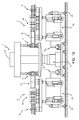
Figure 18 is a frontal view of the article-handling machine ofFigure 17 . -
Number 1 inFigures 17 and18 indicates as a whole a labelling machine for applying labels (not-shown) to respective articles 11 (only schematically shown inFigures 17 and18 ), containers for pourable food product in the embodiment shown. - In particular,
labelling machine 1 is a so-called "roll-fed" labelling machine. -
Labelling machine 1 substantially comprises (Figure 1 ) : - a
stator 2; - a
carousel 3, which rotates about an axis A, vertical in use, with respect tostator 2, and advances a succession of spacedarticles 11 along an arc-shaped path P; - a pair of
modular labelling groups 4, which are arranged on the periphery ofcarousel 3. -
Carousel 3 comprises a radiallyouter periphery 14 with respect to axis A and a plurality of pair ofdocking elements 5 for dockingrespective labelling groups 4 tocarousel 3 -
Docking elements 5 are arranged radially inner with respect toperiphery 14. - Furthermore, it is possible to identify, for each
labelling group 4, a direction G, which is radial with respect to axis A. - In the following of the present description, only one
labelling group 4 will be described, being all labellinggroups 4 identical to one another. -
Labelling group 4 is in the embodiment shown a so-called "roll-fed" labelling group and substantially comprises (Figures 17 and18 ), in the embodiment shown,: - a pair of
shafts 6 for rotatably supporting relative reels (off which a strip of labels is unwound and fed along a feed an application station 15); - a plurality of
guide rollers 16 for guiding the strip along the feed path; - a cutting element (not-shown) for cutting, one after the other, labels from the strip;
- a
glue roller 12 for applying glue onto cut labels; and - a
transfer element 13 for transferring cut and glue-covered labels along an arc-shaped trajectory toapplication station 15. -
Labelling group 4 comprises (Figures 1 to 8 ) a frame 10 (indicated only inFigure 17 ), which supportsshafts 6,rollers 16,glue roller 12 andtransfer element 13. - In the following of the description, the expression "frontward", "rearward", "lateral", "top", "bottom" refer to the position of the
labelling module 4 with respect ofcarousel 3 shown inFigures 1 to 8 . -
Frame 10 comprises: - a
frontward wall 20; - a
rearward wall 21, which is opposite towall 20 and parallel towall 20; - a pair of opposite
lateral walls 22 which lie parallel to axis A and are orthogonally interposed betweenwalls - a
bottom wall 23, which is interposed orthogonally betweenwalls walls 16 and faces afloor 24; and - a
top wall 25, which is opposite and parallel towall 23. -
Frame 10 further comprises a pair ofdocking elements 40. - In the embodiment shown,
docking elements 40 protrude fromwall 20 on the opposite side ofwalls 21. - Furthermore,
floor 24 lies on a plane substantially orthogonal to axis A. - In detail,
labelling group 4 can be set in: - an initial approach position (
Figures 1 and 2 ), in whichlabelling group 4 is not docked tocarousel 3, and in which correspondingdocking elements - a pre-docked position (
Figures 3 and 4 ), in whichwalls floor 24 and in which correspondingdocking elements - a fully docked position (
Figures 5 and 6 ), in whichwalls floor 24 and in which correspondingdocking elements docking elements - a docked and levelled position (
Figures 7 and 8 ), in whichwalls floor 24 and in which correspondingdocking elements - In the embodiment shown,
walls group 4 is in the initial approach position. Furthermore,walls group 4 is in the fully docked position. - Advantageously,
labelling group 4 is rotatable about an axis H between a first angular position, in which it is in the pre-docked position and in the fully docked position (Figures 3 to 6 ) and a second angular position, in which it is in the docked and levelled position (Figures 7 and 8 ). - Axis H is in the embodiment shown, parallel to axis A.
- Still more precisely,
labelling group 4 is set: - in the first angular position (
Figures 1 and 2 ), when it is in the initial approach position; and - in the second angular position (
Figures 7 and 8 ), when it is in the docked and levelled position. - When it is in the pre-docked position,
labelling group 4 rotates tangentially with respect to axis H, from the respective first angular position (Figures 3 and 4 ) to the respective angular second position (Figures 5 and 6 ) reached in the fully docked position. -
Docking elements 5 compriserespective seats 48.Seats 48 are, in the embodiments shown, shaped as conical surfaces having respective axes I parallel to axes A, H. - Alternatively, one
seat 48 is conical around relative axis I and theother seat 48 is V-shaped around relative axis I. -
Seats 48 are open towardsbodies 49 and taper on the opposite side ofbodies 49, proceeding parallel to axis H. -
Docking elements 40 are shaped as partiallyspherical bodies 49 having respective axes J. -
Bodies 49 are free to tilt inside seats 48 about respective axes I, when respective axes I, J are inclined with respect to one another. - When
bodies 49 pivot insiderelative seats 48,labelling group 4 is set in the pre-docked position. -
Bodies 49 are blocked insideseats 48, when respective axes I coincide with corresponding axes J. - When
bodies 49 are blocked insideseats 48,labelling group 4 is set in the fully docked position and then is straightened into the docked and levelled position. - As
bodies 49 pivot insiderelative seats 48,labelling group 4 tangentially rotates about axis H from the first angular position towards the second angular position. - This tangential rotation of
labelling group 4 is preferably caused by a torque about axis H generated by the weight oflabelling group 4. - Alternatively, a not-shown actuator for cause or ease the rotation of
labelling group 4 tangentially about axis H from the pre-docked position to the fully docked position. - Furthermore,
labelling group 4 comprises a pair ofsupport elements 26, which rest onfloor 24 when labellinggroup 4 is in the docked and levelled posiiton, so as to support labelling group 4 (Figures 7 and 8 ). - In the embodiment shown in
Figures 1 to 8 ,support elements 26 compriserespective pedestals 27. -
Pedestals 27 are selectively movable along respective axes B between: - respective extended and raised positions (
Figures 7 and 8 ), in which they rest onfloor 24; and - respective withdrawn and lowered positions (
Figures 1 to 6 ), in which they are spaced and raised fromfloor 24. - When labelling
module 4 is in the initial approach position (Figures 1 and 2 ) or in the docked and levelled position (Figures 7 and 8 ), axis A and B are parallel to one another. - Still more precisely, pedestals 27 are arranged in respective withdrawn and raised position, when labelling
group 4 is set in the initial approach position or in the pre-docking position. -
Pedestals 27 are arranged in the respective extended and lowered position, when labellinggroup 4 is set in the docked and levelled position. -
Labelling group 4 further comprisesactuators 28 for selectively movingrespective pedestals 27 parallel to respective axes B between respective extended positions and withdrawn positions. -
Pedestals 27 comprise, each,: - a
housing 29 fixed with respect to axis B; - a
stem 30 elongated and movable along axis B with respect tohousing 29 upon activation ofrespective actuator 27; and - a
planar surface 31 which projects fromrespective stem 30 orthogonally, transversally in the embodiment shown, to axis B and parallel tofloor 24. - In particular,
surface 31 is a spherically mounted pivot plate, which is free to rotate for adjusting its position with respect to the irregularities and inclinations offloor 24 -
Pedestals 27 andactuators 28 protrude fromwall 21 on the opposite side ofwall 20. -
Labelling group 4 further comprises: - a pair of frontwards
wheels 35, which rotate about a common rotation axis E; and - a pair of
rearwards wheels 45, which rotate about a common rotation axis F. -
Wheels 35 are interposed betweenwall 20 andwheels 45. -
Wheels 35 are interposed betweenwheels 45 andwall 21. -
Wheels 35 are movable along an axis C parallel to axis B between: - respective extended and lowered positions (
Figures 1 and 2 ), in which they are lowered rest onfloor 24; and - respective withdrawn and raised positions (
Figures 3 to 8 ), in which they are spaced and raised fromfloor 24. - More precisely,
wheels 35 are arranged in respective extended and lowered positions, when labellinggroup 4 is arranged in the initial approach position. -
Wheels 35 are arranged in the respective withdrawn and raised positions, when labellinggroup 4 is arranged in the pre-docked position, in the fully docked position and in the docked and levelled position. -
Labelling group 4 further comprises a pair ofactuators 36 for selectively movingrespective wheels 35 parallel to respective axes C between respective extended positions and withdrawn positions. - In detail,
labelling group 4 comprises, for eachwheel 35,: - a
housing 37, which is fixed with respect to relative axis C; and - a
stem 38, which is slidable along relative axis C upon activation ofactuator 36 and is docked to arelative wheel 35. -
Housings 37, relative stems 38 andrelative wheels 35 project fromrespective walls 22 on respective lateral sides offrame 10. -
Wheels 45 are movable along respective axis D parallel to axes B, C between: - respective extended and lowered positions (
Figures 1 to 6 ), in which they are rest onfloor 24;
and - respective withdrawn and raised positions (
Figures 7 and 8 ), in which they are spaced and raised fromfloor 24. - More precisely,
wheels 45 are arranged in respective extended and raised positions, when labellinggroup 4 is arranged in the initial approach position, in the pre-docked position or in the fully docked position. -
Wheels 45 are also arranged in respective withdrawn and lowered positions, when labellinggroup 4 is arranged in the docked and levelled position. - Furthermore,
wheels 45 are movable about axis D between: - respective first angular positions (
Figures 1 to 4 ,7 and 8 ), in which they lie on respective planes parallel to direction G; and - respective second angular positions (
Figures 5 and 6 ), in which they lie on respective planes transversal to direction G. - More precisely,
wheels 45 are arranged in respective first angular positions, when labellinggroup 4 is arranged in the initial approach position, in the pre-docked position and in the docked and levelled position (Figures 1 to 4 ,7 and 8 ). -
Wheels 45 rotate from the respective first angular positions to the respective second angular positions, when labellinggroup 4 is arranged in the fully docked position (Figures 5 and 6 ). - In this way, the rotation of
labelling group 4 about axis H is eased by the fact thatwheels 45 are in the respective second angular positions. - In the embodiment shown, the rotation of
wheels 45 from the respective first position to the respective second positions is manual. - Alternatively, the rotation of
wheels 45 from the respective first position to the respective second positions can be caused by a not-shown cam, as a result of the inclination oflabelling group 4 with respect tofloor 24. -
Labelling group 4 further comprises, for eachwheel 45, arespective actuator 51 for selectively movingwheel 45 parallel to respective axis D between respective extended and lowered position, and withdrawn and raised position. - In detail,
labelling group 4 comprises, for eachwheel 45,: - a
housing 46, which is fixed with respect to relative axis D; and - a
stem 47, which is slidable along relative axis D upon activation ofactuator 51 and is connected to arelative wheel 45. -
Housings 46, stem 47 andrelative wheels 45 project fromrespective walls 22 on respective lateral side offrame 10. - When labelling
module 4 is in the initial approach position (Figures 1 and 2 ) or in the docked and levelled position (Figures 7 and 8 ), axis C, D are parallel to axes A, B. -
Wall 23 is closer tofloor 24 in the docked and levelled position (Figures 7 and 8 ) than in the initial approach position (Figures 1 and 2 ). - In other words, labelling
group 4 is raised in the initial approach position, and lowered in the docked and levelled position with respect tofloor 24. - The docking of
labelling groups 4 tocarousel 3 is described with reference to only onelabelling group 4 and starting from a condition (Figures 1 and 2 ), in whichlabelling group 4 is in the initial approach position. - In greater detail,
labelling group 4 is in the first angular position with respect to axis A (Figure 2 ),bodies 49 are spaced from and aligned withrespective seats 48 parallel to axis A,wheels Figures 1 and 2 ). - Due to the inevitable positioning errors,
walls walls 22 define a slight angle with direction G, when labellinggroup 4 is in the initial approach position (Figures 1 and 2 ). - Starting from the initial approach position,
wheels 35 are moved in the respective withdrawn and raised positions by using actuators 36 (Figures 3 and 4 ). In this way,labelling group 4 is inclined with respect tofloor 24 withwall 20 closer tofloor 24 than wall 21 (Figures 3 and 4 ). The inclination oflabelling group 4 causes the engagement ofbodies 49 insiderelative seats 48 defined bycarousel 3. - At this stage,
labelling group 4 is in the pre-docked position, in which axes I, J ofseats 48 andbodies 49 are inclined with one another and in whichbodies 49 can pivot insiderelative seats 48. - Afterwards,
wheels 45 rotate (Figures 5 and 6 ) from the respective first angular positions towards the respective second angular positions either manually or by means of the not-shown cam. - In this way,
labelling group 4 withwheels 45 in respective second angular positions and withbodies 49 insideseats 48 can roll overwheels 45 about axis H up to whenbodies 49 are blocked insideseats 48 and, therefore,labelling group 4 is in the fully docked position. - The rotation of
labelling group 4 about axis H is caused or at least eased by the torque generated about axis H by the weight of thelabelling group 4 in the inclined position with respect tofloor 24 and can be eased by using the not-shown actuator. - The rotation of
labelling group 4 about axis H causes the pivoting ofbodies 49 insiderelative seats 48, up to when axes I, J are coincident andbodies 49 are blocked inseats 48. - At this stage,
labelling group 4 is in the fully docked position. - Then,
wheels 45 are rotated back - either manually or by means of the not-shown cam - into respective second positions, and raised in respective withdrawn and raised positions by usingactuators 51;pedestals 27 are moved in respective extended and lowered position by usingrespective actuators 28. - At this stage,
labelling group 4 is supported onfloor 24 byrespective pedestals 27 in the docked and levelled position. - With reference to
Figures 9 to 16 , 4' indicates, as a whole, a modular labelling group according to a second embodiment of the present invention. - Labelling group 4' is similar to
labelling group 4 and will be described hereinafter only as far as it differs therefrom; corresponding or equivalent parts oflabelling groups 4, 4' will be indicated where possible by the same reference numbers. - Labelling group 4' differs from
labelling group 4 in that support elements 26' are defined byrespective wheels 45. - Furthermore, labelling group 4' differs from
labelling group 4 for not comprising pedestals 27. - The operation of labelling group 4' is similar to
labelling group 4 and is described only insofar as it differs from that oflabelling group 4 for not comprisingpedestal 27. - With reference to
Figures 15 and 16 ,wheels 45 are in respective first angular positions and remain in respective lowered positions when labellinggroup 4 is set in the docked and levelled position. - In this way, labelling group 4' is supported by
wheels 45 only, when set in the docked and levelled position. - From an analysis of the features of
modular labelling group 4, 4' and method made according to the present invention, the advantages it allows to obtain are apparent. - In particular,
labelling group 4, 4' can rotate about axis H between the first angular position reached in the pre-docked position and the second angular position reached in the fully docked position. - As a result, the rotation of
labelling group 4, 4' in the pre-docked position about axis H causes the tilting ofbodies 49 insiderespective seats 48 up to when axes I, J are aligned with one another andlabelling group 4, 4' is accordingly in the fully docked position. - In this way, the docking of
labelling group 4, 4' tocarousel 3 is particularly eased. - This effect is relevant especially when labelling
group 4, 4' is particularly heavy, and/or the surface offloor 24 is not regular. - As a matter of fact, in this situation,
wheels 45 arranged in the second angular position ease the rotation oflabelling group 4, 4' about axis H. - Thanks to the fact that
labelling group 4, 4' is inclined with respect tofloor 24 in the pre-docked position, the weight ofinclined labelling group 4, 4' generates a torque about axis H, which contributes or causes the rotation oflabelling group 4, 4' in the fully docked position withwheels 45 in the second angular position. - Finally,
labelling group 4, 4' is supported on the floor bysupport element 26, 26' either bywheels 45 arranged in the respective second lowered position or bypedestals 27 arranged in the respective second lowered position. - In this way, the docking of
labelling group 4, 4' tocarousel 3 is eased, when labellinggroup 4, 4' is particularly heavy or whenfloor 24 is not regular. - The presence of
support element 26, 26' resting onfloor 24 furthermore strongly enhances the stability oflabelling group 4, 4' set in the docked and levelled position. - Finally, it is apparent that modifications and variants not departing from the scope of protection of the claims may be made to modular
operative group 4, 4' and to the method. - In particular, modular
operative group 4, 4' could be adapted to carry out an operation, other than labelling, ontoarticles 11, e.g. a blowing, rinsing, filling or capping operation. - Still more precisely,
labelling group 4, 4' could be different from the so-called "roll-fed" labelling group. - Furthermore,
labelling group 4, 4' could not comprisewheels 35. - In this case,
labelling group 4, 4' would be arranged in the initial approach position by making use of a trans-pallet - or any other detachable transport unit or vehicle - and inclined in the pre-docked position with respect tofloor 24 by making use of the same trans-pallet.
Claims (22)
- A method of docking a modular operative group (4, 4') to a carousel (3) of an article-handling machine (1), in particular a labelling machine,;
said modular operative group (4, 4') being adapted to carry out an operation, in particular a labelling operation, onto a plurality of articles (11) advanced by said carousel (3);
said method comprising the step i) of arranging said modular operative group (4, 4') in a fully docked position, in which first docking means (40, 49) carried by said modular operative group (4, 4') and second docking means (5, 48) carried by said carousel (3) are firmly blocked with respect to one another;
said method further comprising the steps of:ii) arranging said modular operative group (4, 4') in a pre-docked position, in which said first docking means (40, 49) and said second docking means (5, 48) cooperate with one another and can tilt with respect to one another about an axis (H) integral with said carousel (3); andiii) rotating said modular operative group (4, 4') about said axis (H) from a first angular position assumed in said pre-docked position to a second angular position assumed in said fully docked position, so as to cause the relative movement of said first docking means (40, 49) and second docking means (5, 48) up to when they are firmly blocked with respect to one another and said modular operative group (4, 4') is in said fully docked position. - The method of claim 1, characterized in that said step iii) comprises a step iv) of rotating at least one first wheel (45) of said modular operative group (4, 4') about said axis (H) from:- a first angular position, in which it rests on a floor (24) and lies on a plane parallel to a direction (G) radial with respect to said axis (H); and towards- a second angular position, in which it is rests on said floor (24) and lies on a plane transversal to said direction (G), so as to ease the rotation of said modular operative group (4, 4') about said axis (H).
- The method of claim 1 or 2, characterized in that said step ii) comprises the step of v) inclining said modular operative group (4, 4') with respect to said axis (H) up to reach a position in which said first docking means (40, 49) and said second docking means (5, 48) cooperate with one another and can tilt with respect to one another.
- The method of claim 3, characterized in that said step ii) causes said step iii).
- The method of claims 3 or 4, characterized by comprising the step vi) of straightening said modular operative group (4, 4') with respect to said floor (24) from said fully docked position to a docked and levelled position.
- The method of any one of the foregoing claims, characterized by comprising the step vii) of arranging said modular operative group (4, 4') in an initial approach position, in which said first docking means (40, 49) and said second docking means (5, 48) are aligned and spaced with respect to one another parallel to said axis (H);
said step vii) being carried out before said step ii) . • - The method of any one of claims 3 to 6, characterized in that said step ii) comprises the steps viii) of moving said second wheel (35) from a first lowered position in which it rests on said floor (24) to a first raised position, in which it is detached from said floor (24).
- The method of any one claims 5 to 7, characterized in that said step vi) comprises the step ix) of supporting said modular operative group (4, 4') arranged in a docked and levelled position by using at least one support element (26, 26'; 27, 45), which rests on said floor (24).
- The method of claim 8, when depending on claims 2 to 7, characterized in that said step ix) comprises the step x) of resting said modular operative group (4, 4') on said floor (24) by means of said first wheel (45) only; said first wheel (45) being arranged in a second lowered position, in which it rests on said floor (24);
- The method of claim 8, characterized in that said step ix) comprises the step xi) of moving a pedestal element (27) from a third raised position in which it is spaced from said floor (24) to a third lowered position in which it rests on said floor (24).
- The method of claim 10, characterized in that said step ix) comprises the step xii) of moving said first wheel (45) in a second raised position, in which it is detached from said floor (24), so as to support said modular operative group (4, 4') on said floor (24) by means of said pedestal (27) only.
- The method of claim 5, characterized by comprising the step xiii) of lowering said modular operative group (4, 4') with respect to said floor (24), when moving modular operative group (4, 4') from said initial approach position to said docked and levelled position.
- A modular operative group (4, 4') for carrying out an operation, in particular a labelling operation, on a plurality of articles (11), comprising first docking means (40, 8), which are configured to be:- either firmly blocked, in use, with respect to second docking means (5, 48) carried by said carousel (3), when said modular operative group (4, 4') is arranged in a fully docked position; or- to cooperate with said second docking means (5, 48) in such a way that said first docking means (40, 8) and said second docking means (5, 48) can tilt with respect to one another, when said modular operative group (4, 4') is arranged in a pre-docked position;
characterized in that said modular operative group (4, 4') is rotatable about a first axis (H) between a first angular position, in which it is set in said pre-docked position and a second angular position, in which it is set in said fully docked position. - The modular operative group of claim 13, characterized by comprising at least one first wheel (45), which is rotatable about a second axis (D) orthogonal to a third rotation axis (F) of said first wheel (45) between:- a first angular position, in which it rests on a floor (24) and lies on a first plane parallel to said first axis (H); and- a second angular position, in which it rests on said floor (24) and lies on a second plane transversal to said first plane and to said first axis (H).
- The modular operative group of claim 14, characterized in that said at least one first wheel (45) is movable between:- a first raised position, in which it is spaced, in use, from said floor (24); and- a first lowered position, in which it rests, in use, on said floor (24).
- The modular operative group of any one of claims 13 to 15, characterized by comprising at least one second wheel (35), which is movable between:- a second raised position, in which it is spaced, in use, from said floor (24); and- a second lowered position, in which it rests, in use, on said floor (24);
said second wheel (35) being arranged in said second raised position, when said labelling group (4, 4') is in said pre-docked position and in said fully docked position. - The modular operative group of any one of claims 13 to 16, characterized by comprising at least one support element (26, 26'; 27, 45), which is adapted to rest, in use, on said floor (24) when said modular operative group (4, 4') is in a docked and levelled position, so as to wholly support said modular operative group (4, 4').
- The modular operative group of claim 17, characterized in that said support element (26, 26'; 27, 45) is a pedestal element (27), which is movable between:- a third raised position, in which it is spaced, in use, from the floor (24); and- a third lowered position, in which it rests, un use, on said floor (24) and supports completely said modular operative group (4');
said pedestal element (27) assuming, in use, said third lowered position, when said modular operative group (4') is arranged in said docked and levelled position. - The modular operative group of claim 17, when depending on any one of claims 14 to 16, characterized in that said support element (26, 26' ; 27, 45) is said first wheel (45);
said first wheel (45) being arranged in said first lowered position when said modular operative group (4) is in said docked and levelled position. - The modular operative group of any one of claims 13 to 19, characterized in that said first docking means (40; 49) comprises a partially spherical element (49) having a fourth symmetry axis (J) .
- An article-handling machine for carrying out an operation on a plurality of articles (11), comprising:- a carousel (3), which is adapted to advance, in use, said article to which said operation has to be carried out towards said modular operative group (4, 4') and to move away, in use, from said modular operative group (4, 4') said articles (11) onto which said operation has been carried out; and- a modular operative group (4, 4') group according to any one of claims 13 to 20;
said first docking means (40, 49) and said second docking means (5, 48) defining at least one joint, which allows said first docking means (40, 49) to pivot inside said second docking means (5, 48) and said whole modular operative group (4, 4') to rotate about said first axis (H) integral with said carousel (3), up to when said modular operative group (4, 4') reaches said fully docked position. - The article handling machine of claim 21, characterized in that said second docking means (5, 48) comprise at least one seat (48) having a fifth symmetry axis (J);
said fourth and fifth axes (J, I) being inclined with respect to one another, when said modular labelling group (4, 4') is in said pre-docked position and being parallel to one another, when said modular labelling group (4, 4') is in said fully docked position.
Priority Applications (1)
| Application Number | Priority Date | Filing Date | Title |
|---|---|---|---|
| EP14198075.5A EP3034420A1 (en) | 2014-12-15 | 2014-12-15 | A method of docking a modular labelling group to a labelling machine, and a modular labelling group |
Applications Claiming Priority (1)
| Application Number | Priority Date | Filing Date | Title |
|---|---|---|---|
| EP14198075.5A EP3034420A1 (en) | 2014-12-15 | 2014-12-15 | A method of docking a modular labelling group to a labelling machine, and a modular labelling group |
Publications (1)
| Publication Number | Publication Date |
|---|---|
| EP3034420A1 true EP3034420A1 (en) | 2016-06-22 |
Family
ID=52278357
Family Applications (1)
| Application Number | Title | Priority Date | Filing Date |
|---|---|---|---|
| EP14198075.5A Withdrawn EP3034420A1 (en) | 2014-12-15 | 2014-12-15 | A method of docking a modular labelling group to a labelling machine, and a modular labelling group |
Country Status (1)
| Country | Link |
|---|---|
| EP (1) | EP3034420A1 (en) |
Citations (4)
| Publication number | Priority date | Publication date | Assignee | Title |
|---|---|---|---|---|
| EP1493671B1 (en) | 2003-07-02 | 2006-10-25 | Khs Ag | Mobile module carrier |
| WO2011027372A1 (en) * | 2009-09-04 | 2011-03-10 | Kosme S.R.L. | Labelling machine |
| EP2594498A1 (en) * | 2011-11-18 | 2013-05-22 | Sidel S.p.a. Con Socio Unico | Labelling machine |
| EP2712820A1 (en) * | 2012-09-28 | 2014-04-02 | Sidel S.p.A. Con Socio Unico | Labelling machine |
-
2014
- 2014-12-15 EP EP14198075.5A patent/EP3034420A1/en not_active Withdrawn
Patent Citations (4)
| Publication number | Priority date | Publication date | Assignee | Title |
|---|---|---|---|---|
| EP1493671B1 (en) | 2003-07-02 | 2006-10-25 | Khs Ag | Mobile module carrier |
| WO2011027372A1 (en) * | 2009-09-04 | 2011-03-10 | Kosme S.R.L. | Labelling machine |
| EP2594498A1 (en) * | 2011-11-18 | 2013-05-22 | Sidel S.p.a. Con Socio Unico | Labelling machine |
| EP2712820A1 (en) * | 2012-09-28 | 2014-04-02 | Sidel S.p.A. Con Socio Unico | Labelling machine |
Similar Documents
| Publication | Publication Date | Title |
|---|---|---|
| US10023334B2 (en) | Full motion wrapping apparatus | |
| CN108473222B (en) | Conveyor for containers | |
| US10633200B2 (en) | Sealing and de-stacking | |
| EP2502834B1 (en) | Modular labeling station | |
| US20150013914A1 (en) | Labelling unit of containers | |
| EP3173361B1 (en) | Transport system for packaging machines | |
| WO2016013743A1 (en) | Large pipe high speed cutter | |
| CN103974879A (en) | Machine for composite package, packaging method and winding means | |
| US8739959B2 (en) | Arrangement for machining workpieces | |
| US20170166344A1 (en) | Method, a transfer drum and an apparatus for labeling articles | |
| EP3177536B1 (en) | Labeling machine | |
| FI125432B (en) | Process and plant for cooling of discs and chillers | |
| JP6048693B2 (en) | Device and method for removing containers from a conveyor line and returning them to the conveyor line | |
| EP3034420A1 (en) | A method of docking a modular labelling group to a labelling machine, and a modular labelling group | |
| EP3175950B1 (en) | Machine to process bars made of aluminium, light alloys, pvc or the like | |
| EP3031737B1 (en) | Labelling machine and method of docking a modular labelling group to a labelling machine | |
| TWI680914B (en) | Labeling machine and label guiding method | |
| WO2016079951A1 (en) | Method for splitting glass plate and splitting device for same | |
| US20150291299A1 (en) | Heat Shrink Device for a Bottom of a Sleeve Label | |
| JP2010155690A (en) | Direction changing device | |
| JP2004525013A (en) | A machine that presents tires with the axis horizontal | |
| EP2886475B1 (en) | A labelling unit for applying a label onto an article | |
| JP3899069B2 (en) | Equipment for attaching extensible sleeves | |
| JP4596160B2 (en) | Cutting machine | |
| CN211303645U (en) | Make things convenient for loudspeaker combination point gum machine of unloading |
Legal Events
| Date | Code | Title | Description |
|---|---|---|---|
| PUAI | Public reference made under article 153(3) epc to a published international application that has entered the european phase |
Free format text: ORIGINAL CODE: 0009012 |
|
| AK | Designated contracting states |
Kind code of ref document: A1 Designated state(s): AL AT BE BG CH CY CZ DE DK EE ES FI FR GB GR HR HU IE IS IT LI LT LU LV MC MK MT NL NO PL PT RO RS SE SI SK SM TR |
|
| AX | Request for extension of the european patent |
Extension state: BA ME |
|
| 17P | Request for examination filed |
Effective date: 20160728 |
|
| RBV | Designated contracting states (corrected) |
Designated state(s): AL AT BE BG CH CY CZ DE DK EE ES FI FR GB GR HR HU IE IS IT LI LT LU LV MC MK MT NL NO PL PT RO RS SE SI SK SM TR |
|
| 17Q | First examination report despatched |
Effective date: 20180226 |
|
| STAA | Information on the status of an ep patent application or granted ep patent |
Free format text: STATUS: THE APPLICATION IS DEEMED TO BE WITHDRAWN |
|
| 18D | Application deemed to be withdrawn |
Effective date: 20180710 |