EP3034346A1 - Vehicle cooling device - Google Patents
Vehicle cooling device Download PDFInfo
- Publication number
- EP3034346A1 EP3034346A1 EP15200648.2A EP15200648A EP3034346A1 EP 3034346 A1 EP3034346 A1 EP 3034346A1 EP 15200648 A EP15200648 A EP 15200648A EP 3034346 A1 EP3034346 A1 EP 3034346A1
- Authority
- EP
- European Patent Office
- Prior art keywords
- static electricity
- self
- radiator
- discharge type
- type static
- Prior art date
- Legal status (The legal status is an assumption and is not a legal conclusion. Google has not performed a legal analysis and makes no representation as to the accuracy of the status listed.)
- Granted
Links
Images


Classifications
-
- B—PERFORMING OPERATIONS; TRANSPORTING
- B60—VEHICLES IN GENERAL
- B60K—ARRANGEMENT OR MOUNTING OF PROPULSION UNITS OR OF TRANSMISSIONS IN VEHICLES; ARRANGEMENT OR MOUNTING OF PLURAL DIVERSE PRIME-MOVERS IN VEHICLES; AUXILIARY DRIVES FOR VEHICLES; INSTRUMENTATION OR DASHBOARDS FOR VEHICLES; ARRANGEMENTS IN CONNECTION WITH COOLING, AIR INTAKE, GAS EXHAUST OR FUEL SUPPLY OF PROPULSION UNITS IN VEHICLES
- B60K11/00—Arrangement in connection with cooling of propulsion units
- B60K11/02—Arrangement in connection with cooling of propulsion units with liquid cooling
- B60K11/04—Arrangement or mounting of radiators, radiator shutters, or radiator blinds
-
- F—MECHANICAL ENGINEERING; LIGHTING; HEATING; WEAPONS; BLASTING
- F01—MACHINES OR ENGINES IN GENERAL; ENGINE PLANTS IN GENERAL; STEAM ENGINES
- F01P—COOLING OF MACHINES OR ENGINES IN GENERAL; COOLING OF INTERNAL-COMBUSTION ENGINES
- F01P11/00—Component parts, details, or accessories not provided for in, or of interest apart from, groups F01P1/00 - F01P9/00
-
- B—PERFORMING OPERATIONS; TRANSPORTING
- B60—VEHICLES IN GENERAL
- B60K—ARRANGEMENT OR MOUNTING OF PROPULSION UNITS OR OF TRANSMISSIONS IN VEHICLES; ARRANGEMENT OR MOUNTING OF PLURAL DIVERSE PRIME-MOVERS IN VEHICLES; AUXILIARY DRIVES FOR VEHICLES; INSTRUMENTATION OR DASHBOARDS FOR VEHICLES; ARRANGEMENTS IN CONNECTION WITH COOLING, AIR INTAKE, GAS EXHAUST OR FUEL SUPPLY OF PROPULSION UNITS IN VEHICLES
- B60K11/00—Arrangement in connection with cooling of propulsion units
-
- B—PERFORMING OPERATIONS; TRANSPORTING
- B60—VEHICLES IN GENERAL
- B60R—VEHICLES, VEHICLE FITTINGS, OR VEHICLE PARTS, NOT OTHERWISE PROVIDED FOR
- B60R16/00—Electric or fluid circuits specially adapted for vehicles and not otherwise provided for; Arrangement of elements of electric or fluid circuits specially adapted for vehicles and not otherwise provided for
- B60R16/02—Electric or fluid circuits specially adapted for vehicles and not otherwise provided for; Arrangement of elements of electric or fluid circuits specially adapted for vehicles and not otherwise provided for electric constitutive elements
- B60R16/06—Electric or fluid circuits specially adapted for vehicles and not otherwise provided for; Arrangement of elements of electric or fluid circuits specially adapted for vehicles and not otherwise provided for electric constitutive elements for removing electrostatic charges
-
- F—MECHANICAL ENGINEERING; LIGHTING; HEATING; WEAPONS; BLASTING
- F01—MACHINES OR ENGINES IN GENERAL; ENGINE PLANTS IN GENERAL; STEAM ENGINES
- F01P—COOLING OF MACHINES OR ENGINES IN GENERAL; COOLING OF INTERNAL-COMBUSTION ENGINES
- F01P11/00—Component parts, details, or accessories not provided for in, or of interest apart from, groups F01P1/00 - F01P9/00
- F01P11/14—Indicating devices; Other safety devices
-
- F—MECHANICAL ENGINEERING; LIGHTING; HEATING; WEAPONS; BLASTING
- F01—MACHINES OR ENGINES IN GENERAL; ENGINE PLANTS IN GENERAL; STEAM ENGINES
- F01P—COOLING OF MACHINES OR ENGINES IN GENERAL; COOLING OF INTERNAL-COMBUSTION ENGINES
- F01P3/00—Liquid cooling
- F01P3/18—Arrangements or mounting of liquid-to-air heat-exchangers
-
- F—MECHANICAL ENGINEERING; LIGHTING; HEATING; WEAPONS; BLASTING
- F01—MACHINES OR ENGINES IN GENERAL; ENGINE PLANTS IN GENERAL; STEAM ENGINES
- F01P—COOLING OF MACHINES OR ENGINES IN GENERAL; COOLING OF INTERNAL-COMBUSTION ENGINES
- F01P9/00—Cooling having pertinent characteristics not provided for in, or of interest apart from, groups F01P1/00 - F01P7/00
-
- F—MECHANICAL ENGINEERING; LIGHTING; HEATING; WEAPONS; BLASTING
- F04—POSITIVE - DISPLACEMENT MACHINES FOR LIQUIDS; PUMPS FOR LIQUIDS OR ELASTIC FLUIDS
- F04D—NON-POSITIVE-DISPLACEMENT PUMPS
- F04D29/00—Details, component parts, or accessories
- F04D29/02—Selection of particular materials
- F04D29/023—Selection of particular materials especially adapted for elastic fluid pumps
-
- H—ELECTRICITY
- H01—ELECTRIC ELEMENTS
- H01T—SPARK GAPS; OVERVOLTAGE ARRESTERS USING SPARK GAPS; SPARKING PLUGS; CORONA DEVICES; GENERATING IONS TO BE INTRODUCED INTO NON-ENCLOSED GASES
- H01T19/00—Devices providing for corona discharge
-
- H—ELECTRICITY
- H05—ELECTRIC TECHNIQUES NOT OTHERWISE PROVIDED FOR
- H05F—STATIC ELECTRICITY; NATURALLY-OCCURRING ELECTRICITY
- H05F3/00—Carrying-off electrostatic charges
-
- H—ELECTRICITY
- H05—ELECTRIC TECHNIQUES NOT OTHERWISE PROVIDED FOR
- H05F—STATIC ELECTRICITY; NATURALLY-OCCURRING ELECTRICITY
- H05F3/00—Carrying-off electrostatic charges
- H05F3/04—Carrying-off electrostatic charges by means of spark gaps or other discharge devices
-
- F—MECHANICAL ENGINEERING; LIGHTING; HEATING; WEAPONS; BLASTING
- F01—MACHINES OR ENGINES IN GENERAL; ENGINE PLANTS IN GENERAL; STEAM ENGINES
- F01P—COOLING OF MACHINES OR ENGINES IN GENERAL; COOLING OF INTERNAL-COMBUSTION ENGINES
- F01P11/00—Component parts, details, or accessories not provided for in, or of interest apart from, groups F01P1/00 - F01P9/00
- F01P11/02—Liquid-coolant filling, overflow, venting, or draining devices
-
- F—MECHANICAL ENGINEERING; LIGHTING; HEATING; WEAPONS; BLASTING
- F01—MACHINES OR ENGINES IN GENERAL; ENGINE PLANTS IN GENERAL; STEAM ENGINES
- F01P—COOLING OF MACHINES OR ENGINES IN GENERAL; COOLING OF INTERNAL-COMBUSTION ENGINES
- F01P11/00—Component parts, details, or accessories not provided for in, or of interest apart from, groups F01P1/00 - F01P9/00
- F01P11/04—Arrangements of liquid pipes or hoses
-
- F—MECHANICAL ENGINEERING; LIGHTING; HEATING; WEAPONS; BLASTING
- F01—MACHINES OR ENGINES IN GENERAL; ENGINE PLANTS IN GENERAL; STEAM ENGINES
- F01P—COOLING OF MACHINES OR ENGINES IN GENERAL; COOLING OF INTERNAL-COMBUSTION ENGINES
- F01P3/00—Liquid cooling
- F01P3/20—Cooling circuits not specific to a single part of engine or machine
-
- F—MECHANICAL ENGINEERING; LIGHTING; HEATING; WEAPONS; BLASTING
- F01—MACHINES OR ENGINES IN GENERAL; ENGINE PLANTS IN GENERAL; STEAM ENGINES
- F01P—COOLING OF MACHINES OR ENGINES IN GENERAL; COOLING OF INTERNAL-COMBUSTION ENGINES
- F01P5/00—Pumping cooling-air or liquid coolants
- F01P5/02—Pumping cooling-air; Arrangements of cooling-air pumps, e.g. fans or blowers
- F01P5/06—Guiding or ducting air to, or from, ducted fans
-
- F—MECHANICAL ENGINEERING; LIGHTING; HEATING; WEAPONS; BLASTING
- F02—COMBUSTION ENGINES; HOT-GAS OR COMBUSTION-PRODUCT ENGINE PLANTS
- F02B—INTERNAL-COMBUSTION PISTON ENGINES; COMBUSTION ENGINES IN GENERAL
- F02B63/00—Adaptations of engines for driving pumps, hand-held tools or electric generators; Portable combinations of engines with engine-driven devices
- F02B63/04—Adaptations of engines for driving pumps, hand-held tools or electric generators; Portable combinations of engines with engine-driven devices for electric generators
Definitions
- the invention relates to a vehicle cooling device.
- a vehicle is publicly known, in which a discharge device such as a discharge antenna is mounted on an engine or an engine-related member of the vehicle, and high-voltage electricity, static electricity and so on generated and charged in the engine area is discharged and emitted outside, thereby improving fuel economy (for example, see Japanese Patent Application Publication JP 5-238438 A ).
- JP 5-238438 A it is known that static electricity is charged to a vehicle, and that static electricity charged to a vehicle have some kind of influence on driving of the vehicle. However, it is not clearly known why and how the static electricity charged to a vehicle affects driving of the vehicle. However, without knowing why and how static electricity charged to a vehicle affects driving of the vehicle, it is not possible to appropriately deal with static electricity charged to a vehicle.
- the inventors paid attention especially to a radiator, a condenser, and a fan cover including a fan for cooling the radiator and the condenser, and studied an influence of static electricity charged to the radiator or the condenser on driving of a vehicle.
- the inventors found that static electricity charged to the radiator or the condenser greatly affects cooling efficiency.
- the inventors found an adequate static electricity elimination method required for improving cooling efficiency.
- the invention relates to a vehicle cooling device.
- a vehicle cooling device includes: at least one of a radiator and a condenser; a fan cover including a fan configured to cool the at least one of the radiator and the condenser; the radiator, the condenser and the fan cover being positively charged; a connecting part that connects the fan cover and the at least one of the radiator and the condenser with each other; and a self-discharge type static electricity eliminator.
- the self-discharge type static electricity eliminator is installed on a non-conductive wall surface of the connecting part, and is configured to decrease an electric charge amount of a part of the non-conductive wall surface within a limited range, centered on a location where the self-discharge type static electricity eliminator is installed, static elimination of the at least one of the radiator and the condenser being performed by the 1f-discharge type static electricity eliminator.
- the self-discharge type static electricity eliminator on the non-conductive wall surface of the connecting part that connects the radiator or the condenser with the fan cover, static electricity elimination of the radiator or the condenser is performed, thereby improving cooling efficiency.
- the self-discharge type static electricity eliminator may be installed at a position where air passes the non-conductive wall surface of the connecting part. Thereby, the static electricity discharge is continuously performed.
- the fan cover may be made of a non-conductive synthetic resin material.
- the self-discharge type static electricity eliminator may be installed on a wall surface of the fan cover around the connecting part.
- the at least one of the radiator and the condenser and the fan cover may be connected with each other through a detachable connector.
- the self-discharge type static electricity eliminator may be installed on the connector.
- the at least one of the radiator and the condenser may include the radiator.
- a tank of the radiator may be made of a non-conductive synthetic resin material.
- the tank may be connected with the fan cover.
- the self-discharge type static electricity eliminator may be installed on a wall surface of the tank around the connecting part.
- the self-discharge type static electricity eliminator may be formed of metallic foil preferably made from ductile metal such as aluminum or copper, that is adhered to the non-conductive wall surface by a conductive adhesive.
- the self-discharge type static electricity eliminator may be formed of a conductive thin film.
- the self-discharge type static electricity eliminator may be formed integrally on the non-conductive wall surface.
- the self-discharge type static electricity eliminator may have a corner part configured to cause self-discharge.
- the self-discharge type static electricity eliminator has a sharp end part, preferably a plurality of shard end parts.
- the self-discharge type static electricity eliminator may have an elongated rectangular flat shape, preferably having a longitudinal length between 50mm and 100mm and/or having a thickness between 0.05mm and 0.2mm.
- the self-discharge type static electricity eliminator may be formed of a conductive thin film that is formed integrally on the non-conductive wall surface.
- FIG. 1 shows an exploded perspective view showing an illustration of a vehicle cooling device including a fan cover 1, a radiator 2, and a condenser 3.
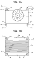
- a fan 1a and an electric motor 1b ( FIG. 2A ) for driving the fan 1a are mounted on the fan cover 1.
- the fan cover 1 shown in FIG. 1 is extremely simplified.
- the fan cover 1 is made of a non-conductive synthetic resin material.
- the radiator 2 shown in FIG. 1 is a radiator for an engine cooling water.
- the radiator 2 includes upper and lower tanks 2a, and a core 2b arranged between the upper and lower tanks 2a.
- the upper and lower tanks 2a are made of a non-conductive synthetic resin material
- the core 2b is made of a metallic material.
- the condenser 3 is a condenser for an air conditioner.
- the condenser 3 includes upper and lower tanks 3a, and a core 3b.
- the core 3b is arranged between the upper and lower tanks 3a.
- the entire condenser 3 is made of a metallic material.
- an inverter converter radiator 4 is arranged below the condenser 3.
- the inverter converter radiator 4 is used for a hybrid engine including an electric motor.
- Reference numeral 4a indicates a core of the inverter converter radiator 4.
- the radiator 2 is supported by a vehicle body or a chassis through a support member made of, for example, a rubber material.
- the fan cover 1 is coupled with one side of the radiator 2 by connectors 5 and connectors 6.
- the connectors 5 are arranged on both sides of each of an upper end part of the fan cover 1 and an upper end part of the radiator 2.
- the connectors 6 are arranged on both sides of each of a lower end part of the fan cover 1 and a lower end part of the radiator 2.
- the condenser 3 is coupled with the other side of the radiator 2, together with the inverter converter radiator 4, by connectors 7.
- the connectors 7 are arranged on both sides of each of an upper end part and a lower end part of the condenser 3.
- FIG. 2A shows a front view of the fan cover 1 seen along arrow A in FIG. 1
- FIG. 2B is a front view of the radiator 2 seen along arrow B in FIG. 1
- flat-shaped flanges 8a extend upwardly from both sides of an upper end part of the fan cover 1, and the connectors 5 on one side are formed on the flanges 8a
- flat-shaped flanges 8b extend downwardly from both sides of a lower end part of the fan cover 1, and the connectors 6 on one side are formed on the flange 8b
- FIG. 3 shows a plane sectional view of the connector 5. As shown in FIG.
- the connector 5 has an opening 8c formed in the flange 8a, and a pair of elastic hook members 8d.
- the elastic hook members 8d can be snap-fitted into the opening 8c.
- the pair of elastic hook members 8d is made of a non-conductive synthetic resin material, and formed integrally with the upper tank 2a of the radiator 2.
- FIG. 4A and FIG. 4B show the connector 6.
- the connector 6 has a latching part 8f and a U-shaped groove part 8e.
- the latching part 8f is formed in the lower tank 2a of the radiator 2 and has an enlarged head and a small-diameter shaft part as shown in FIG. 4A .
- the U-shaped groove part 8e is formed in the lower end part of the flange 8b of the fan cover 1 and is fitted to the small-diameter shaft part.
- the latching part 8f is made of a non-conductive synthetic resin material, and is formed integrally with the lower tank 2a of the radiator 2.
- the U-shaped groove parts 8e formed in the lower end parts of the flanges 8b of the fan cover 1 are first fitted to the small-diameter shaft parts of the latching parts 8f formed in the lower tank 2a of the radiator 2. Thereafter, the openings 8c formed in the flanges 8a of the fan cover 1 are fitted into the elastic hook members 8d that are formed integrally with the upper tank 2a of the radiator 2. Thus, the fan cover 1 is coupled with the radiator 2.
- Static electricity is also generated as components of an engine, and components of a braking device move relative to each other. Further, static electricity is generated due to air that flows on and is in frictional contact with an outer peripheral surface of the vehicle when the vehicle is running.
- the static electricity generated as above charges the body, engine, and so on of the vehicle, and the fan cover 1, the radiator 2, the condenser 3, and the inverter converter radiator 4 are also charged. Further, rotation of the electric motor 1b for the fan 1a, which is supported by the fan cover 1, generates static electricity. As a result, a large amount of charge is present on the surface of the fan cover 1 made of a non-conductive synthetic resin material.
- FIG. 6A shows air flowing along a surface of a thin wall 9 that is positively charged. Since air tends to be positively charged, FIG. 6A shows a case where positively-charged air flows along the surface of the thin wall 9 that is positively charged.
- solid-line arrows show air flows when a voltage value on the surface of the thin wall 9 is low. In this case, air flows along the surface of the thin wall 9.
- broken-line arrows show air flows when voltage value on the surface of the thin wall 9 is high. In this case, air flows so as to be separated from the surface of the thin wall 9 at a point where the surface of the thin wall 9 curves downwardly, or a point where the air flow is easily separated from the surface of the thin wall 9.
- FIG. 6B shows measured values of a velocity ratio U/U ⁇ , at point X ( FIG. 6A ).
- the "U ⁇ " is a flow velocity of a main flow of air that flows along the surface of the thin wall 9 in FIG. 6A .
- the "U” is a flow velocity at a point separated from the surface of the thin wall 9 by a distance S in FIG. 6A .
- Each point shown as a black rhombus in FIG. 6B shows a case where the surface of the thin wall 9 is not positively charged, and each point shown as a black quadrangle in FIG. 6B shows a case where the surface of the thin wall 9 is positively charged. It is understood from FIG.
- the surface of the thin wall 9 has a shape that easily causes separation of the air flow
- the air flow is not separated when the surface of the thin wall 9 is not positively charged, but the air flow could be separated when the surface of the thin wall 9 is positively charged.
- a degree of separation of an air flow is greater than that in the case where the surface of the thin wall 9 is not positively charged. In this way, it is confirmed that, when the surface of the thin wall 9 is positively charged, an air flow is separated from the surface of the thin wall 9 or separation of air happens based on electrical repulsive force.
- FIG. 7C show examples of this self-discharge type static electricity eliminator.
- FIG. 7A and FIG. 7B show a plan view and a side sectional view of a self-discharge type static electricity eliminator 10 according to the invention, respectively.
- FIG. 7C shows a side sectional view of another self-discharge type static electricity eliminator 10 according to the invention.
- the self-discharge type static electricity eliminator 10 has an elongated rectangular flat shape, and is also formed of metallic foil 11 that is adhered onto the surface of the thin wall 9 by a conductive adhesive 12.
- the self-discharge type static electricity eliminator 10 is formed of a conductive thin film that is formed integrally with the surface of the thin wall 9.
- static electricity elimination of a part of the fan cover 1, the radiator 2, the condenser 3, and the inverter converter radiator 4 is performed by using the self-discharge type static electricity eliminators 10.
- FIG. 8A shows a case where the self-discharge type static electricity eliminator 10 shown in FIG. 7A and FIG. 7B is installed on the surface of the thin wall 9.
- the self-discharge type static electricity eliminator 10 is installed on the surface of the thin wall 9 as stated above, an electric charge amount of the surface of the thin wall 9 is reduced within a limited range (having a diameter D) shown as a broken line, the limited range being centered on the location where the self-discharge type static electricity eliminator 10 is installed as shown in FIG. 8B .
- a limited range having a diameter D
- the thin wall 9 is made of a non-conductive synthetic resin material.
- the thin wall 9 is made of a non-conductive synthetic resin material as stated above, inside of the thin wall 9 is not charged, and the surface of the thin wall 9 is charged. As stated earlier, it is confirmed that the surfaces of the fan cover 1, and the tanks 2a of the radiator 2 shown in FIG. 1 are charged positively.
- static electricity elimination is performed on parts of the surface of the fan cover 1 and so on. Therefore, assuming a case where static electricity elimination is performed on parts of the surface of the fan cover 1 and so on, FIG. 9A shows a case where the surface of the thin wall 9 is positively charged.
- the self-discharge type static electricity eliminator 10 is formed of the metallic foil 11 adhered to the surface of the thin wall 9 by the conductive adhesive 12. Since both the metallic foil 11 and the conductive adhesive 12 have conductivity, inside of the metallic foil 11, i.e., inside of the self-discharge type static electricity eliminator 10, is positively charged.
- Voltage of the self-discharge type static electricity eliminator 10 is about the same as voltage on the surface of the thin wall 9 around the self-discharge type static electricity eliminator 10. Therefore, the voltage of the self-discharge type static electricity eliminator 10 is quite high. Meanwhile, because air tends to be positively charged as stated earlier, positive air ions (expressed as + in a circle) are present in a part of air. In this case, in comparison between electrical potential of the air ion, and electrical potential of the self-discharge type static electricity eliminator 10, the electrical potential of the self-discharge type static electricity eliminator 10 is much higher than the electrical potential of the air ion.
- an air ion with an increased positive charge amount (expressed as ++ in a circle) is generated as shown in FIG. 9B , and the air ion with the increased positive charge amount is dispersed into circumambient air.
- the amount of air ions with the increased positive charge amount is extremely smaller than the amount of air flowing around the self-discharge type static electricity eliminator 10.
- Discharge between an air ion and the self-discharge type static electricity eliminator 10 happens between the air ion and the corner part 13 of the self-discharge type static electricity eliminator 10, or between the air ion and sharp end parts 14 in a peripheral part of the self-discharge type static electricity eliminator 10. Therefore, in order to make discharge happen easily between an air ion and the self-discharge type static electricity eliminator 10, it is preferred that a number of sharp end parts 14 are formed, in addition to the corner part 13, in the peripheral part of the self-discharge type static electricity eliminator 10. Hence, when fabricating the self-discharge type static electricity eliminator 10, it is preferred that metallic foil is cut so that burrs like the sharp end parts 14 are formed in the section when fabricating the metallic foil 11 by cutting large metallic foil.
- the metallic foil 11 of the self-discharge type static electricity eliminator 10 shown in FIG. 7A and FIG. 7B is made of ductile metal such as aluminum or copper.
- the metallic foil 11 in the embodiment of the invention is formed of aluminum foil.
- a longitudinal length of the aluminum foil 11 used in the embodiment of the invention is between about 50 mm and 100 mm, and a thickness is between about 0.05 mm and 0.2 mm.
- a diameter D of the limited range shown as the broken line in FIG. 8B in which voltage is decreased, is between about 150 mm and 200 mm.
- An aluminum tape, in which a layer of the conductive adhesive 12 is formed on the aluminum foil 11, may be cut and used as the self-discharge type static electricity eliminator 10. Further, as shown in FIG.
- the self-discharge type static electricity eliminator 10 may be formed of a conductive thin film that is formed integrally with the surface of the thin wall 9. In this case, it is also preferred that a number of sharp end parts 14 are formed, in addition to the corner part 13, in a peripheral part of the conductive thin film as shown in FIG. 9B .
- cooling efficiency was deteriorated when the voltage values on outer peripheral surfaces of the core 2b of the radiator 2, the core 3b of the condenser 3, and the core 4a of the inverter converter radiator 4 were high. It was also found that, in this case, cooling efficiency was improved when the self-discharge type static electricity eliminator 10 is installed on non-conductive wall surface of connecting part that connect the radiator 2 and the fan cover 1 with each other.
- FIG. 5A is an enlarged sectional perspective view of a part of the core 2b of the radiator 2
- FIG. 5B is a vertical sectional view taken long the line B - B in FIG. 5A .
- reference numeral 20 indicates water pipes that are spaced apart from each other at intervals
- reference numeral 21 indicates corrugated cooling fins arranged between the water pipes 20. Air flows between the corrugated cooling fins 21, and cooling water flowing inside the water pipes 20 is thus cooled.
- FIG. 5B solid-line arrows show air flows when voltage of the surface of the core 2b of the radiator 2, or voltage of the surfaces of the water pipe 20 and the corrugated cooling fin 21 is low, and, in this case, air flows along the surface of the corrugated cooling fin 21.
- the voltage of the surface of the core 2b of the radiator 2, or the voltage of the surfaces of the water pipe 20 and the corrugated cooling fin 21 becomes high due to static electricity charge, air flowing along the surface of the corrugated cooling fin 21 is separated from the surface of the corrugated cooling fin 21 by electrical repulsive force as shown as broken-line arrows in FIG. 5B .
- electrical repulsive force as shown as broken-line arrows in FIG. 5B .
- air has to flow away from the surface of the corrugated cooling fin 21.
- the self-discharge type static electricity eliminator 10 is installed on a connecting part that connects the radiator 2 and the fan cover 1 with each other in order to decrease the voltage of the surface of the core 2b of the radiator 2, or the voltage of the surfaces of the water pipes 20 and the corrugated cooling fins 21.
- the self-discharge type static electricity eliminators 10 are installed on outer wall surfaces of the flanges 8a, 8b of the fan cover 1 as shown in FIG. 2A .
- the voltage value of the core 2a of the radiator 2 is maintained low by installing one or more self-discharge type static electricity eliminators 10 on outer wall surfaces of the connectors 5, 6, thereby improving cooling efficiency of the radiator 2.
- the self-discharge type static electricity eliminators 10 are installed on non-conductive wall surfaces of the connecting parts that connect the radiator 2 and the fan cover 1 with each other.
- one or more self-discharge type static electricity eliminators 10 are installed on the non-conductive wall surfaces of the connecting parts that connect the radiator 2 and the fan cover 1 with each other.
- the fan cover 1 is not connected with the radiator 2, and the fan cover 1 is directly coupled with the condenser 3 in order to cool the condenser 3.
- one or more self-discharge type static electricity eliminators 10 are installed on non-conductive wall surfaces of connecting parts that connect the condenser 3 and the fan cover 1 with each other.
- the inverter converter radiator 4 is not used.
- the cooling device of the vehicle includes at least one of the radiator 2 and the condenser 3, the fan cover 1 and the self-discharge type static electricity eliminator 10.
- the fan cover 1 includes the fan 1a for cooling the radiator 2 or the condenser 3.
- the radiator 2, the condenser 3, and the fan cover 1 are positively charged.
- the self-discharge type static electricity eliminator 10 is installed on a non-conductive wall surface and decreases an electric charge amount the on non-conductive wall surface within a limited range centered on a location where the self-discharge type static electricity eliminator 10 is installed.
- the self-discharge type static electricity eliminator 10 is installed on a non-conductive wall surface of a connecting part that connects the radiator 2 or the condenser 3 with the fan cover 1 to perform static electricity elimination of the radiator 2 or the condenser 3. At least one of the radiator 2 and the condenser 3 may be regarded as a charged part of the invention.
- the self-discharge type static electricity eliminator 10 is installed on a wall surface of the fan cover 1 around the foregoing connecting part. Further, the radiator 2 or the condenser 3 is connected with the fan cover 1 through the detachable connectors 5, 6. In another embodiment of the invention, the self-discharge type static electricity eliminators 10 are installed on the connectors 5, 6.
- the tanks 2a of the radiator 2 are made of a non-conductive synthetic resin material, and, at the same time, the tanks 2a of the radiator 2 are connected with the fan cover 1.
- the self-discharge type static electricity eliminators 10 are installed on wall surfaces of the radiator tanks 2a around the foregoing connecting parts. Embodiments of the invention are not limited to the embodiments described in the specification.
Landscapes
- Engineering & Computer Science (AREA)
- Mechanical Engineering (AREA)
- Chemical & Material Sciences (AREA)
- Combustion & Propulsion (AREA)
- General Engineering & Computer Science (AREA)
- Transportation (AREA)
- Physics & Mathematics (AREA)
- Thermal Sciences (AREA)
- Plasma & Fusion (AREA)
- Elimination Of Static Electricity (AREA)
- Architecture (AREA)
- Structural Engineering (AREA)
- Electric Propulsion And Braking For Vehicles (AREA)
- Cooling, Air Intake And Gas Exhaust, And Fuel Tank Arrangements In Propulsion Units (AREA)
- Cooling Or The Like Of Electrical Apparatus (AREA)
Abstract
Description
- The invention relates to a vehicle cooling device.
- A vehicle is publicly known, in which a discharge device such as a discharge antenna is mounted on an engine or an engine-related member of the vehicle, and high-voltage electricity, static electricity and so on generated and charged in the engine area is discharged and emitted outside, thereby improving fuel economy (for example, see
Japanese Patent Application Publication JP 5-238438 A - As described in
JP 5-238438 A - The inventors paid attention especially to a radiator, a condenser, and a fan cover including a fan for cooling the radiator and the condenser, and studied an influence of static electricity charged to the radiator or the condenser on driving of a vehicle. As a result of the study, the inventors found that static electricity charged to the radiator or the condenser greatly affects cooling efficiency. Then, based on this fact found, the inventors found an adequate static electricity elimination method required for improving cooling efficiency.
- The invention relates to a vehicle cooling device.
- A vehicle cooling device according to an aspect of the invention includes: at least one of a radiator and a condenser; a fan cover including a fan configured to cool the at least one of the radiator and the condenser; the radiator, the condenser and the fan cover being positively charged; a connecting part that connects the fan cover and the at least one of the radiator and the condenser with each other; and a self-discharge type static electricity eliminator. The self-discharge type static electricity eliminator is installed on a non-conductive wall surface of the connecting part, and is configured to decrease an electric charge amount of a part of the non-conductive wall surface within a limited range, centered on a location where the self-discharge type static electricity eliminator is installed, static elimination of the at least one of the radiator and the condenser being performed by the 1f-discharge type static electricity eliminator.
- According to the aspect of the invention, by installing the self-discharge type static electricity eliminator on the non-conductive wall surface of the connecting part that connects the radiator or the condenser with the fan cover, static electricity elimination of the radiator or the condenser is performed, thereby improving cooling efficiency.
- In the aspect of the invention, the self-discharge type static electricity eliminator may be installed at a position where air passes the non-conductive wall surface of the connecting part. Thereby, the static electricity discharge is continuously performed.
- In the aspect of the invention, the fan cover may be made of a non-conductive synthetic resin material.
- In the above configuration, the self-discharge type static electricity eliminator may be installed on a wall surface of the fan cover around the connecting part.
- In the aspect of the invention, the at least one of the radiator and the condenser and the fan cover may be connected with each other through a detachable connector. The self-discharge type static electricity eliminator may be installed on the connector.
- In the aspect of the invention, the at least one of the radiator and the condenser may include the radiator. A tank of the radiator may be made of a non-conductive synthetic resin material. The tank may be connected with the fan cover. The self-discharge type static electricity eliminator may be installed on a wall surface of the tank around the connecting part.
- In the aspect of the invention, the self-discharge type static electricity eliminator may be formed of metallic foil preferably made from ductile metal such as aluminum or copper, that is adhered to the non-conductive wall surface by a conductive adhesive.
- In the above configuration, the self-discharge type static electricity eliminator may be formed of a conductive thin film.
- In the above configuration, the self-discharge type static electricity eliminator may be formed integrally on the non-conductive wall surface.
- In the above configuration, the self-discharge type static electricity eliminator may have a corner part configured to cause self-discharge.
- In the above configuration, the self-discharge type static electricity eliminator has a sharp end part, preferably a plurality of shard end parts.
- In the above configuration, the self-discharge type static electricity eliminator may have an elongated rectangular flat shape, preferably having a longitudinal length between 50mm and 100mm and/or having a thickness between 0.05mm and 0.2mm.
- In the aspect of the invention, the self-discharge type static electricity eliminator may be formed of a conductive thin film that is formed integrally on the non-conductive wall surface.
- Features, advantages, and technical and industrial significance of exemplary embodiments of the invention will be described below with reference to the accompanying drawings, in which like numerals denote like elements, and wherein:
-
FIG. 1 is an exploded perspective view showing an illustration of a fan cover, a radiator, and a condenser according to an embodiment of the invention; -
FIG. 2A and FIG. 2B are front views of the fan cover and the radiator, respectively, according to the embodiment of the invention; -
FIG. 3 is a side sectional view of the fan cover and the radiator shown inFIG. 1 ,FIG. 2A and FIG. 2B ; -
FIG. 4A and FIG. 4B are views showing connectors of the fan cover and the radiator shown inFIG. 1 ,FIG. 2A and FIG. 2B ; -
FIG. 5A and FIG. 5B are views for explaining an air flow in a core of the radiator according to the embodiment of the invention; -
FIG 6A and FIG. 6B are views for explaining a change of an air flow according to the embodiment of the invention; -
FIG. 7A, FIG. 7B and FIG. 7C are views showing a self-discharge type static electricity eliminator according to the embodiment of the invention; -
FIG. 8A and FIG. 8B are views for explaining a static electricity elimination effect by the self-discharge type static electricity eliminator according to the embodiment of the invention; and -
FIG. 9A and FIG. 9B are views for explaining a self-discharge effect according to the embodiment of the invention; - Herein below, an embodiment of the invention is explained with reference to
FIG. 1 to FIG. 9B .FIG. 1 shows an exploded perspective view showing an illustration of a vehicle cooling device including afan cover 1, aradiator 2, and acondenser 3. With reference toFIG. 1 , afan 1a and anelectric motor 1b (FIG. 2A ) for driving thefan 1a are mounted on thefan cover 1. Although an actual structure of thefan cover 1 is complex, thefan cover 1 shown inFIG. 1 is extremely simplified. In the embodiment shown inFIG. 1 , thefan cover 1 is made of a non-conductive synthetic resin material. - Meanwhile, the
radiator 2 shown inFIG. 1 is a radiator for an engine cooling water. In the embodiment shown inFIG. 1 , theradiator 2 includes upper andlower tanks 2a, and acore 2b arranged between the upper andlower tanks 2a. In the embodiment shown inFIG. 1 , the upper andlower tanks 2a are made of a non-conductive synthetic resin material, and thecore 2b is made of a metallic material. In the embodiment shown inFIG. 1 , thecondenser 3 is a condenser for an air conditioner. Thecondenser 3 includes upper andlower tanks 3a, and acore 3b. Thecore 3b is arranged between the upper andlower tanks 3a. Theentire condenser 3 is made of a metallic material. Further, in the embodiment shown inFIG. 1 , aninverter converter radiator 4 is arranged below thecondenser 3. Theinverter converter radiator 4 is used for a hybrid engine including an electric motor.Reference numeral 4a indicates a core of theinverter converter radiator 4. - The
radiator 2 is supported by a vehicle body or a chassis through a support member made of, for example, a rubber material. Thefan cover 1 is coupled with one side of theradiator 2 byconnectors 5 andconnectors 6. Theconnectors 5 are arranged on both sides of each of an upper end part of thefan cover 1 and an upper end part of theradiator 2. Theconnectors 6 are arranged on both sides of each of a lower end part of thefan cover 1 and a lower end part of theradiator 2. Thecondenser 3 is coupled with the other side of theradiator 2, together with theinverter converter radiator 4, byconnectors 7. Theconnectors 7 are arranged on both sides of each of an upper end part and a lower end part of thecondenser 3. When thefan 1a is driven by theelectric motor 1b, suction force of thefan 1a first circulate outside air inside thecondenser 3 and theinverter converter radiator 4. At this time, refrigerant flowing inside thecondenser 3 and theinverter converter radiator 4 is cooled, respectively. Then, outside air is circulated inside theradiator 2, and, at that time, cooling water inside theradiator 2 is cooled. -
FIG. 2A shows a front view of thefan cover 1 seen along arrow A inFIG. 1 , andFIG. 2B is a front view of theradiator 2 seen along arrow B inFIG. 1 . As shown inFIG. 2A , flat-shapedflanges 8a extend upwardly from both sides of an upper end part of thefan cover 1, and theconnectors 5 on one side are formed on theflanges 8a. Meanwhile, as shown inFIG. 2A , flat-shapedflanges 8b extend downwardly from both sides of a lower end part of thefan cover 1, and theconnectors 6 on one side are formed on theflange 8b.FIG. 3 shows a plane sectional view of theconnector 5. As shown inFIG. 3 , theconnector 5 has anopening 8c formed in theflange 8a, and a pair ofelastic hook members 8d. Theelastic hook members 8d can be snap-fitted into theopening 8c. The pair ofelastic hook members 8d is made of a non-conductive synthetic resin material, and formed integrally with theupper tank 2a of theradiator 2. -
FIG. 4A and FIG. 4B show theconnector 6. Theconnector 6 has a latchingpart 8f and aU-shaped groove part 8e. The latchingpart 8f is formed in thelower tank 2a of theradiator 2 and has an enlarged head and a small-diameter shaft part as shown inFIG. 4A . TheU-shaped groove part 8e is formed in the lower end part of theflange 8b of thefan cover 1 and is fitted to the small-diameter shaft part. The latchingpart 8f is made of a non-conductive synthetic resin material, and is formed integrally with thelower tank 2a of theradiator 2. When fixing thefan cover 1 to theradiator 2, theU-shaped groove parts 8e formed in the lower end parts of theflanges 8b of thefan cover 1 are first fitted to the small-diameter shaft parts of the latchingparts 8f formed in thelower tank 2a of theradiator 2. Thereafter, theopenings 8c formed in theflanges 8a of thefan cover 1 are fitted into theelastic hook members 8d that are formed integrally with theupper tank 2a of theradiator 2. Thus, thefan cover 1 is coupled with theradiator 2. - Once a vehicle is run, each part of tires comes into contact with and is separated from a road surface repeatedly, and static electricity is thus generated. Static electricity is also generated as components of an engine, and components of a braking device move relative to each other. Further, static electricity is generated due to air that flows on and is in frictional contact with an outer peripheral surface of the vehicle when the vehicle is running. The static electricity generated as above charges the body, engine, and so on of the vehicle, and the
fan cover 1, theradiator 2, thecondenser 3, and theinverter converter radiator 4 are also charged. Further, rotation of theelectric motor 1b for thefan 1a, which is supported by thefan cover 1, generates static electricity. As a result, a large amount of charge is present on the surface of thefan cover 1 made of a non-conductive synthetic resin material. - When a large amount of charge is present on the
fan cover 1, a voltage value of the surface of thefan cover 1 becomes high. When the voltage value of the surface of thefan cover 1 becomes high, a voltage value of the surface of theradiator 2, which is coupled with thefan cover 1 through theconnectors radiator 2 becomes high, voltage values of surfaces of thecondenser 3 and theinverter converter radiator 4, which are coupled with theradiator 2 through theconnectors 7, become high. In fact, it is confirmed that the surface of thefan cover 1, the surface of theradiator 2, the surface of thecondenser 3, and the surface of theinverter converter radiator 4 are positively charged. Moreover, it is confirmed that there are instances where the voltage values of the surfaces of thefan cover 1, theradiator 2, thecondenser 3, and theinverter converter radiator 4 become as high as 1000V or higher. - It is confirmed that, when a voltage value becomes high on a surface of a thin wall made of a non-conductive synthetic resin material, a flow of air along the surface of the thin wall changes. Thus, the inventors conducted an experiment to confirm how an air flow along the surface of the thin wall changes in accordance with a voltage value on the surface of the thin wall, and confirmed the following phenomena.
-
FIG. 6A shows air flowing along a surface of athin wall 9 that is positively charged. Since air tends to be positively charged,FIG. 6A shows a case where positively-charged air flows along the surface of thethin wall 9 that is positively charged. InFIG. 6A , solid-line arrows show air flows when a voltage value on the surface of thethin wall 9 is low. In this case, air flows along the surface of thethin wall 9. On the contrary, broken-line arrows show air flows when voltage value on the surface of thethin wall 9 is high. In this case, air flows so as to be separated from the surface of thethin wall 9 at a point where the surface of thethin wall 9 curves downwardly, or a point where the air flow is easily separated from the surface of thethin wall 9. -
FIG. 6B shows measured values of a velocity ratio U/U∞, at point X (FIG. 6A ). The "U∞" is a flow velocity of a main flow of air that flows along the surface of thethin wall 9 inFIG. 6A . The "U" is a flow velocity at a point separated from the surface of thethin wall 9 by a distance S inFIG. 6A . Each point shown as a black rhombus inFIG. 6B shows a case where the surface of thethin wall 9 is not positively charged, and each point shown as a black quadrangle inFIG. 6B shows a case where the surface of thethin wall 9 is positively charged. It is understood fromFIG. 6B that, in the case where the surface of thethin wall 9 is positively charged, a velocity boundary layer is separated more from the surface of thethin wall 9 compared to the case where the surface thethin wall 9 is not positively charged. Therefore, in the case where the surface of thethin wall 9 is positively charged, air flows so as to be separated from the surface of thethin wall 9 as shown as the broken-line arrows inFIG. 6A . - As stated above, air tends to be positively charged. Therefore, positive air ions (expressed as + in a circle) are present in a part of air. Accordingly, when the surface of the
thin wall 9 is positively charged, repulsive force acts between the positive air ions and the surface of thethin wall 9. Thus, as shown as the broken-line arrows inFIG. 6A , air flows so as to be separated from the surface of thethin wall 9 at the point where the surface of thethin wall 9 is curved downwardly, or the point where the air flow is easily separated from the surface of thethin wall 9. It is thus confirmed from an experiment that an air flow along the surface of thethin wall 9 is separated from the surface of thethin wall 9 because of positive charge on the surface of thethin wall 9. In this case, it is known that the higher the voltage value becomes on the surface of thethin wall 9, the more the air flow along the surface of thethin wall 9 is separated from the surface of thethin wall 9. - In a case where the surface of the
thin wall 9 has a shape that easily causes separation of the air flow, it is confirmed that the air flow is not separated when the surface of thethin wall 9 is not positively charged, but the air flow could be separated when the surface of thethin wall 9 is positively charged. It is also confirmed that, when the surface of thethin wall 9 is positively charged, a degree of separation of an air flow is greater than that in the case where the surface of thethin wall 9 is not positively charged. In this way, it is confirmed that, when the surface of thethin wall 9 is positively charged, an air flow is separated from the surface of thethin wall 9 or separation of air happens based on electrical repulsive force. - As stated above, when the surface of the
thin wall 9 is positively charged, an air flow becomes different from a flow that is originally intended. In this case, once positive charge on the surface of thethin wall 9 is entirely or partially eliminated, or static electricity elimination of the surface of thethin wall 9 is performed, to decrease the voltage value of the surface of thethin wall 9, it is possible to bring the air flow along the surface of thethin wall 9 back to an air flow in the case where the surface of thethin wall 9 is not positively charged. This means that, by the static electricity elimination, the air flow is restored to an air flow that is originally intended. Thus, the inventors considered a static electricity elimination method for restoring an air flow to one originally intended, and found a static electricity elimination method using a self-discharge type static electricity eliminator.FIG. 7A to FIG. 7C show examples of this self-discharge type static electricity eliminator.FIG. 7A and FIG. 7B show a plan view and a side sectional view of a self-discharge typestatic electricity eliminator 10 according to the invention, respectively.FIG. 7C shows a side sectional view of another self-discharge typestatic electricity eliminator 10 according to the invention. - In the example shown in
FIG. 7A and FIG. 7B , the self-discharge typestatic electricity eliminator 10 has an elongated rectangular flat shape, and is also formed ofmetallic foil 11 that is adhered onto the surface of thethin wall 9 by aconductive adhesive 12. Meanwhile, in the example shown inFIG. 7C , the self-discharge typestatic electricity eliminator 10 is formed of a conductive thin film that is formed integrally with the surface of thethin wall 9. In the embodiment of the invention, static electricity elimination of a part of thefan cover 1, theradiator 2, thecondenser 3, and theinverter converter radiator 4 is performed by using the self-discharge typestatic electricity eliminators 10. Before giving explanation of the static electricity elimination method for a part of thefan cover 1, theradiator 2, thecondenser 3, and theinverter converter radiator 4, a basic static electricity elimination method using the self-discharge typestatic electricity eliminator 10 according to the embodiment of the invention is explained first using an example case where static electricity elimination of the surface of thethin wall 9 is performed by the self-discharge typestatic electricity eliminator 10. -
FIG. 8A shows a case where the self-discharge typestatic electricity eliminator 10 shown inFIG. 7A and FIG. 7B is installed on the surface of thethin wall 9. When the self-discharge typestatic electricity eliminator 10 is installed on the surface of thethin wall 9 as stated above, an electric charge amount of the surface of thethin wall 9 is reduced within a limited range (having a diameter D) shown as a broken line, the limited range being centered on the location where the self-discharge typestatic electricity eliminator 10 is installed as shown inFIG. 8B . As a result, it is confirmed that voltage of the surface of thethin wall 9 within the limited range shown as the broken line inFIG 8B is decreased. - In this case, it is presumed that, because of an effect of the self-discharge type
static electricity eliminator 10 for discharging positive charge, a static electricity elimination effect could be performed on the surface of thethin wall 9 around the location where the self-discharge typestatic electricity eliminator 10 is installed. Next, the static electricity elimination mechanism, which is presumed to be carried out on the surface of thethin wall 9, is explained with reference toFIG. 9A showing an enlarged sectional view of thethin wall 9, andFIG. 9B showing an enlarged view of an end part of the self-discharge typestatic electricity eliminator 10 shown inFIG. 9A . - As stated above, the
thin wall 9 is made of a non-conductive synthetic resin material. When thethin wall 9 is made of a non-conductive synthetic resin material as stated above, inside of thethin wall 9 is not charged, and the surface of thethin wall 9 is charged. As stated earlier, it is confirmed that the surfaces of thefan cover 1, and thetanks 2a of theradiator 2 shown inFIG. 1 are charged positively. In the embodiment of the invention, in order to perform static electricity elimination of theradiator 2 and so on, static electricity elimination is performed on parts of the surface of thefan cover 1 and so on. Therefore, assuming a case where static electricity elimination is performed on parts of the surface of thefan cover 1 and so on,FIG. 9A shows a case where the surface of thethin wall 9 is positively charged. Meanwhile, as stated earlier, the self-discharge typestatic electricity eliminator 10 is formed of themetallic foil 11 adhered to the surface of thethin wall 9 by theconductive adhesive 12. Since both themetallic foil 11 and the conductive adhesive 12 have conductivity, inside of themetallic foil 11, i.e., inside of the self-discharge typestatic electricity eliminator 10, is positively charged. - Voltage of the self-discharge type
static electricity eliminator 10 is about the same as voltage on the surface of thethin wall 9 around the self-discharge typestatic electricity eliminator 10. Therefore, the voltage of the self-discharge typestatic electricity eliminator 10 is quite high. Meanwhile, because air tends to be positively charged as stated earlier, positive air ions (expressed as + in a circle) are present in a part of air. In this case, in comparison between electrical potential of the air ion, and electrical potential of the self-discharge typestatic electricity eliminator 10, the electrical potential of the self-discharge typestatic electricity eliminator 10 is much higher than the electrical potential of the air ion. Therefore, when the air ion comes close to, for example, acorner part 13 of the self-discharge typestatic electricity eliminator 10 as shown inFIG. 9B , a field intensity becomes high between the air ion and thecorner part 13 of the self-discharge typestatic electricity eliminator 10. As a result, discharge happens between the air ion and thecorner part 13 of the self-discharge typestatic electricity eliminator 10. - Once discharge happens between the air ion and the
corner part 13 of the self-discharge typestatic electricity eliminator 10, some electrons of the air ions move into the self-discharge typestatic electricity eliminator 10 as shown inFIG. 9B . Therefore, a positive charge amount of the air ion is increased (expressed as ++ in a circle), and an electron that has moved into the self-discharge typestatic electricity eliminator 10 neutralizes positive charge on the self-discharge typestatic electricity eliminator 10. Once discharge is performed, discharge occurs easily, and, when another air ion comes close to thecorner part 13 of the self-discharge typestatic electricity eliminator 10, discharge happens immediately between the air ion and thecorner part 13 of the self-discharge typestatic electricity eliminator 10. In short, when air moves around the self-discharge typestatic electricity eliminator 10, air ions move close to thecorner part 13 of the self-discharge typestatic electricity eliminator 10 one after another. Therefore, discharge happens continuously between air ions and thecorner part 13 of the self-discharge typestatic electricity eliminator 10. - Once discharge happens continuously between air ions and the
corner part 13 of the self-discharge typestatic electricity eliminator 10, positive charge on the self-discharge typestatic electricity eliminator 10 is neutralized in succession. As a result, a positive charge amount on the self-discharge typestatic electricity eliminator 10 is reduced. Once the positive charge amount on the self-discharge typestatic electricity eliminator 10 is reduced, positive charge on the surface of thethin wall 9 around the self-discharge typestatic electricity eliminator 10 moves into the self-discharge typestatic electricity eliminator 10. Therefore, a positive charge amount on the surface of thethin wall 9 around the self-discharge typestatic electricity eliminator 10 is also reduced. As a result, voltage on the self-discharge typestatic electricity eliminator 10 and the surface of thethin wall 9 around the self-discharge typestatic electricity eliminator 10 is decreased gradually. This effect of decreasing voltage on the self-discharge typestatic electricity eliminator 10 and the surface of thethin wall 9 around the self-discharge typestatic electricity eliminator 10 continues until voltage on the self-discharge typestatic electricity eliminator 10 is decreased and the discharge effect is stopped. As a result, as shown inFIG. 8B , voltage on the surface of thethin wall 9 is decreased within the limited range shown as the broken line, centered on the location where the self-discharge typestatic electricity eliminator 10 is installed. - Meanwhile, as stated earlier, once discharge happens between an air ion and the
corner part 13 of the self-discharge typestatic electricity eliminator 10, an air ion with an increased positive charge amount (expressed as ++ in a circle) is generated as shown inFIG. 9B , and the air ion with the increased positive charge amount is dispersed into circumambient air. The amount of air ions with the increased positive charge amount is extremely smaller than the amount of air flowing around the self-discharge typestatic electricity eliminator 10. When air around the self-discharge typestatic electricity eliminator 10 is stagnant and air ions do not move, discharge does not happen continuously, and voltage on the surface of thethin wall 9 is not decreased. This means that it is necessary to make air around the self-discharge typestatic electricity eliminator 10 flow in order to decrease voltage on the surface of thethin wall 9. During the engine operation, by taking air into the engine, air moves in the engine room including around the self-discharge static type electricity eliminator. - Discharge between an air ion and the self-discharge type
static electricity eliminator 10 happens between the air ion and thecorner part 13 of the self-discharge typestatic electricity eliminator 10, or between the air ion andsharp end parts 14 in a peripheral part of the self-discharge typestatic electricity eliminator 10. Therefore, in order to make discharge happen easily between an air ion and the self-discharge typestatic electricity eliminator 10, it is preferred that a number ofsharp end parts 14 are formed, in addition to thecorner part 13, in the peripheral part of the self-discharge typestatic electricity eliminator 10. Hence, when fabricating the self-discharge typestatic electricity eliminator 10, it is preferred that metallic foil is cut so that burrs like thesharp end parts 14 are formed in the section when fabricating themetallic foil 11 by cutting large metallic foil. - The
metallic foil 11 of the self-discharge typestatic electricity eliminator 10 shown inFIG. 7A and FIG. 7B is made of ductile metal such as aluminum or copper. Themetallic foil 11 in the embodiment of the invention is formed of aluminum foil. Further, a longitudinal length of thealuminum foil 11 used in the embodiment of the invention is between about 50 mm and 100 mm, and a thickness is between about 0.05 mm and 0.2 mm. In this case, a diameter D of the limited range shown as the broken line inFIG. 8B , in which voltage is decreased, is between about 150 mm and 200 mm. An aluminum tape, in which a layer of theconductive adhesive 12 is formed on thealuminum foil 11, may be cut and used as the self-discharge typestatic electricity eliminator 10. Further, as shown inFIG. 7C , the self-discharge typestatic electricity eliminator 10 may be formed of a conductive thin film that is formed integrally with the surface of thethin wall 9. In this case, it is also preferred that a number ofsharp end parts 14 are formed, in addition to thecorner part 13, in a peripheral part of the conductive thin film as shown inFIG. 9B . - As explained earlier, it is confirmed that the voltage values on the surfaces of the
fan cover 1, theradiator 2, thecondenser 3, and theinverter converter radiator 4 become as high as 1000V or higher. In this case, judging from the experiment results shown inFIG. 6A and FIG. 6B , a flow of outside air, or an air flow, which flows inside thecore 2b of theradiator 2, thecore 3b of thecondenser 3, and the core 4a of theinverter converter radiator 4, is changed by the high voltage, which presumably affects cooling efficiency. Thus, an experiment was carried out regarding cooling efficiency. As a result, it was found that cooling efficiency was deteriorated when the voltage values on outer peripheral surfaces of the core 2b of theradiator 2, thecore 3b of thecondenser 3, and the core 4a of theinverter converter radiator 4 were high. It was also found that, in this case, cooling efficiency was improved when the self-discharge typestatic electricity eliminator 10 is installed on non-conductive wall surface of connecting part that connect theradiator 2 and thefan cover 1 with each other. - First of all, the reason for deterioration of cooling efficiency is explained briefly with reference to
FIG. 5A and FIG. 5B by using an example case where a voltage value on the surface of the core 2b of theradiator 2 becomes high.FIG. 5A is an enlarged sectional perspective view of a part of the core 2b of theradiator 2, andFIG. 5B is a vertical sectional view taken long the line B - B inFIG. 5A . InFIG. 5A and FIG. 5B ,reference numeral 20 indicates water pipes that are spaced apart from each other at intervals, andreference numeral 21 indicates corrugated cooling fins arranged between thewater pipes 20. Air flows between thecorrugated cooling fins 21, and cooling water flowing inside thewater pipes 20 is thus cooled. - In
FIG. 5B , solid-line arrows show air flows when voltage of the surface of the core 2b of theradiator 2, or voltage of the surfaces of thewater pipe 20 and the corrugated coolingfin 21 is low, and, in this case, air flows along the surface of the corrugated coolingfin 21. However, when the voltage of the surface of the core 2b of theradiator 2, or the voltage of the surfaces of thewater pipe 20 and the corrugated coolingfin 21 becomes high due to static electricity charge, air flowing along the surface of the corrugated coolingfin 21 is separated from the surface of the corrugated coolingfin 21 by electrical repulsive force as shown as broken-line arrows inFIG. 5B . As a result, air has to flow away from the surface of the corrugated coolingfin 21. - When air has to flow away from the surface of
corrugated cooling fin 21 as stated above, a heat transfer rate from the surface of the corrugated coolingfin 21 to air is reduced. As a result, it becomes impossible to favorably reduce temperature of cooling water flowing inside thewater pipes 20. Thus, cooling efficiency is deteriorated. In this case, if voltage of the surface of the core 2b of theradiator 2, or voltage of the surfaces of thewater pipes 20 and the coolingfins 21 is decreased, air flows along the surface of the corrugated coolingfins 21 as shown as the solid lines inFIG. 5B . As a result, the heat transfer rate from the surfaces of the corrugated coolingfins 21 to air is increased, thereby improving cooling efficiency. Thus, in the embodiment of the invention, the self-discharge typestatic electricity eliminator 10 is installed on a connecting part that connects theradiator 2 and thefan cover 1 with each other in order to decrease the voltage of the surface of the core 2b of theradiator 2, or the voltage of the surfaces of thewater pipes 20 and thecorrugated cooling fins 21. In this case, in the example of the invention, the self-discharge typestatic electricity eliminators 10 are installed on outer wall surfaces of theflanges fan cover 1 as shown inFIG. 2A . - When the self-discharge type
static electricity eliminators 10 are installed on the outer wall surfaces of theflanges fan cover 1, electric charges within certain ranges centered on the self-discharge typestatic electricity eliminators 10 are eliminated by a static electricity elimination effect produced by the self-discharge typestatic electricity eliminators 10, and voltage within the certain ranges centered on the self-discharge typestatic electricity eliminators 10 is decreased. As a result, voltage of the connecting parts, which connect thefan cover 1 and theradiator 2 with each other, is decreased, and, in the embodiment shown inFIG. 1 andFIG. 2A , voltage of theconnectors fan cover 1 and theradiator 2 with each other, is decreased. When the voltage of theconnectors fan cover 1 and theradiator 2 with each other, is decreased, voltage of theradiator 2, which is connected with thefan cover 1 through theconnectors radiator 2 is decreased. - When the voltage of the core 2a of the
radiator 2 is decreased, voltage on the surfaces of thewater pipes 20 and thecorrugated cooling fins 21 is decreased. As a result, as shown as the solid lines inFIG. 5B , air flows along the surfaces of the corrugated coolingfins 21. Since the heat transfer rate from the surfaces of the corrugated coolingfins 21 to air is increased, cooling efficiency is improved. Meanwhile, as stated earlier, when theelectric motor 1b for the fan, which is supported by thefan cover 1, is driven, static electricity is generated. Therefore, as theelectric motor 1b for the fan is driven continuously, a large amount of charge stays on thefan cover 1. As a result, a voltage value of thefan cover 1 remains high. - However, even when the voltage value of the
fan cover 1 is maintained high, by installing the self-discharge typestatic electricity eliminators 10 on the outer wall surfaces of theflanges fan cover 1, voltage of the surface of thefan cover 1 is decreased within the certain ranges centered on the self-discharge typestatic electricity eliminators 10. Therefore, voltage of theconnectors radiator 2. This means that, when voltage of theconnectors static electricity eliminators 10, a voltage value of theradiator 2 is decreased more greatly than the voltage value of thefan cover 1. Thus, cooling efficiency of theradiator 2 is improved. - Meanwhile, as shown in
FIG. 2B , it is also possible to decrease voltage of theconnectors static electricity eliminators 10 by installing the self-discharge typestatic electricity eliminators 10 on outer wall surfaces of the upper andlower tanks 2a of theradiator 2 around theconnectors static electricity eliminators 10 are installed on the outer wall surfaces of the upper andlower tanks 2a of theradiator 2 around theconnectors FIG. 2B , it is still possible to maintain the voltage value of the core 2a of theradiator 2 low. Therefore, in this case, cooling efficiency of theradiator 2 is also improved. - Also, the voltage value of the core 2a of the
radiator 2 is maintained low by installing one or more self-discharge typestatic electricity eliminators 10 on outer wall surfaces of theconnectors radiator 2. In other words, by installing the self-discharge typestatic electricity eliminators 10 on the connecting parts that connect thefan cover 1 and theradiator 2 with each other, it is possible to decrease voltage of theconnectors radiator 2. Hence, according to the embodiment of the invention, the self-discharge typestatic electricity eliminators 10 are installed on non-conductive wall surfaces of the connecting parts that connect theradiator 2 and thefan cover 1 with each other. When the voltage of theradiator 2 is decreased, voltage of theair condenser 3, which is coupled with theradiator 2 through theconnectors 7, is also decreased. Thus, voltage of theinverter converter radiator 4 is decreased. Therefore, heat transfer rates of the core 2b of theair condenser 3, and the core 4a of theinverter converter radiator 4 to air are increased, and, as a result, cooling efficiency is improved in theair condenser 3 and theinverter converter radiator 4. - As stated earlier, according to the embodiment of the invention, one or more self-discharge type
static electricity eliminators 10 are installed on the non-conductive wall surfaces of the connecting parts that connect theradiator 2 and thefan cover 1 with each other. However, in some vehicle models, thefan cover 1 is not connected with theradiator 2, and thefan cover 1 is directly coupled with thecondenser 3 in order to cool thecondenser 3. In this case, one or more self-discharge typestatic electricity eliminators 10 are installed on non-conductive wall surfaces of connecting parts that connect thecondenser 3 and thefan cover 1 with each other. Further, in some vehicle models, theinverter converter radiator 4 is not used. - Therefore, in the embodiment of the invention, the cooling device of the vehicle includes at least one of the
radiator 2 and thecondenser 3, thefan cover 1 and the self-discharge typestatic electricity eliminator 10. Thefan cover 1 includes thefan 1a for cooling theradiator 2 or thecondenser 3. In this vehicle, theradiator 2, thecondenser 3, and thefan cover 1 are positively charged. The self-discharge typestatic electricity eliminator 10 is installed on a non-conductive wall surface and decreases an electric charge amount the on non-conductive wall surface within a limited range centered on a location where the self-discharge typestatic electricity eliminator 10 is installed. The self-discharge typestatic electricity eliminator 10 is installed on a non-conductive wall surface of a connecting part that connects theradiator 2 or thecondenser 3 with thefan cover 1 to perform static electricity elimination of theradiator 2 or thecondenser 3. At least one of theradiator 2 and thecondenser 3 may be regarded as a charged part of the invention. - In one of the embodiments of the invention, the self-discharge type
static electricity eliminator 10 is installed on a wall surface of thefan cover 1 around the foregoing connecting part. Further, theradiator 2 or thecondenser 3 is connected with thefan cover 1 through thedetachable connectors static electricity eliminators 10 are installed on theconnectors tanks 2a of theradiator 2 are made of a non-conductive synthetic resin material, and, at the same time, thetanks 2a of theradiator 2 are connected with thefan cover 1. In yet another embodiment of the invention, the self-discharge typestatic electricity eliminators 10 are installed on wall surfaces of theradiator tanks 2a around the foregoing connecting parts. Embodiments of the invention are not limited to the embodiments described in the specification.
Claims (11)
- A vehicle cooling device characterized by comprising:at least one of a radiator (2) and a condenser (3);a fan cover (1) including a fan (1a) configured to cool the at least one of the radiator (2) and the condenser (3); the radiator, the condenser and the fan cover being positively charged;a connecting part (5, 6) that connects the fan cover (1) and the at least one of the radiator (2) and the condenser (3) with each other; anda self-discharge type static electricity eliminator (10) that is installed on a non-conductive wall surface of the connecting part (5, 6), and is configured to decrease an electric charge amount of a part of the non-conductive wall surface within a limited range (D), centered on a location where the self-discharge type static electricity eliminator (10) is installed, static electricity elimination of the at least one of the radiator (2) and the condenser (3) being performed by the self-discharge type static electricity eliminator (10).
- The vehicle cooling device according to claim 1, wherein
the self-discharge type static electricity eliminator (10) is installed at a position where air passes the non-conductive wall surface of the connecting part (5, 6). - The vehicle cooling device according to claim 1 or 2, wherein
the fan cover (1) is made of a non-conductive synthetic resin material. - The vehicle cooling device according to any one of claims 1 to 3, wherein
the self-discharge type static electricity eliminator (10) is installed on a wall surface of the fan cover (1) around the connecting part (5, 6). - The vehicle cooling device according to any one of claims 1 to 4, wherein
the at least one of the radiator (2) and the condenser (3) and the fan cover (1) are connected with each other through a detachable connector (5, 6), and
the self-discharge type static electricity eliminator (10) is installed on the connector. - The vehicle cooling device according to any one of claims 1 to 5, wherein
the at least one of the radiator (2) and the condenser (3) is the radiator (2),
a tank (2a) of the radiator (2) is made of a non-conductive synthetic resin material,
the tank (2a) is connected with the fan cover (1), and
the self-discharge type static electricity eliminator (10) is installed on a wall surface of the tank (2a) around the connecting part (5,6). - The vehicle cooling device according to claim any one of claims 1 to 6, wherein
the self-discharge type static electricity eliminator (10) is formed of a metallic foil (11), preferably made from ductile metal such as aluminum or copper, that is adhered to the non-conductive wall surface by a conductive adhesive (12). - The vehicle cooling device according to any one of claims 1 to 6, wherein
the self-discharge type static electricity eliminator (10), preferably formed of a conductive thin film, is formed integrally on the non-conductive wall surface. - The vehicle cooling device according to any one of claims 1 to 8, wherein
the self-discharge type static electricity eliminator (10) has a corner part (13) configured to cause self-discharge. - The vehicle cooling device according to any one of the claims 1 to 9, wherein
the self-discharge type static electricity eliminator (10) has a sharp end part (14), preferably a plurality of shard end parts (14). - The vehicle cooling device according to any one of claims 1 to 10, wherein
the self-discharge type static electricity eliminator (10) has an elongated rectangular flat shape, preferably having a longitudinal length between 50mm and 100mm and/or having a thickness between 0.05mm and 0.2mm.
Applications Claiming Priority (1)
| Application Number | Priority Date | Filing Date | Title |
|---|---|---|---|
| JP2014257972A JP6160603B2 (en) | 2014-12-19 | 2014-12-19 | Vehicle cooling device |
Publications (2)
| Publication Number | Publication Date |
|---|---|
| EP3034346A1 true EP3034346A1 (en) | 2016-06-22 |
| EP3034346B1 EP3034346B1 (en) | 2017-05-17 |
Family
ID=54979435
Family Applications (1)
| Application Number | Title | Priority Date | Filing Date |
|---|---|---|---|
| EP15200648.2A Active EP3034346B1 (en) | 2014-12-19 | 2015-12-17 | Vehicle cooling device |
Country Status (7)
| Country | Link |
|---|---|
| US (1) | US9903261B2 (en) |
| EP (1) | EP3034346B1 (en) |
| JP (1) | JP6160603B2 (en) |
| KR (1) | KR101757072B1 (en) |
| CN (1) | CN105715355B (en) |
| BR (1) | BR102015032130A2 (en) |
| RU (1) | RU2632237C2 (en) |
Families Citing this family (22)
| Publication number | Priority date | Publication date | Assignee | Title |
|---|---|---|---|---|
| US10336270B2 (en) | 2013-10-30 | 2019-07-02 | Toyota Jidosha Kabushiki Kaisha | Vehicle and manufacturing method thereof |
| EP2966393B1 (en) * | 2014-07-07 | 2020-10-21 | Valeo Autosystemy SP. Z.O.O. | An integrated bracket for automotive heat exchanger |
| JP6124020B2 (en) | 2014-08-29 | 2017-05-10 | トヨタ自動車株式会社 | Charged charge reduction device for vehicles |
| JP6128093B2 (en) | 2014-10-16 | 2017-05-17 | トヨタ自動車株式会社 | Vehicle intake system |
| JP6201980B2 (en) | 2014-12-25 | 2017-09-27 | トヨタ自動車株式会社 | Vehicle intake system |
| JP6115559B2 (en) | 2014-12-26 | 2017-04-19 | トヨタ自動車株式会社 | Vehicle exhaust system |
| JP6183383B2 (en) | 2015-01-13 | 2017-08-23 | トヨタ自動車株式会社 | vehicle |
| JP6365316B2 (en) | 2015-01-19 | 2018-08-01 | トヨタ自動車株式会社 | Lubricating oil or fuel supply device for vehicles |
| EP3048017B1 (en) | 2015-01-23 | 2017-11-08 | Toyota Jidosha Kabushiki Kaisha | Damping force generation device for vehicle |
| JP6281501B2 (en) | 2015-01-29 | 2018-02-21 | トヨタ自動車株式会社 | Vehicle wheel support device |
| JP6248962B2 (en) | 2015-02-10 | 2017-12-20 | トヨタ自動車株式会社 | Vehicle braking force generator |
| JP6344292B2 (en) * | 2015-04-03 | 2018-06-20 | トヨタ自動車株式会社 | vehicle |
| JP2019078437A (en) * | 2017-10-23 | 2019-05-23 | トヨタ自動車株式会社 | Heat exchanger |
| CN107933463B (en) * | 2017-11-07 | 2019-09-20 | 纳恩博(北京)科技有限公司 | A kind of electrostatic release method and vehicle of vehicle |
| JP7331335B2 (en) * | 2018-07-24 | 2023-08-23 | 株式会社デンソー | assembly |
| WO2020105184A1 (en) | 2018-11-22 | 2020-05-28 | コンティニューム株式会社 | Reticular resin molding and air-conditioner operating method using same |
| JP2020083190A (en) * | 2018-11-29 | 2020-06-04 | トヨタ自動車株式会社 | Air blower |
| CN109532467B (en) * | 2018-12-20 | 2024-01-12 | 天津巴泰克汽车装备有限公司 | New energy electric automobile radiator |
| USD892878S1 (en) * | 2019-02-28 | 2020-08-11 | Resource International Inc. | Transmission cooler for automotive applications |
| USD892877S1 (en) * | 2019-02-28 | 2020-08-11 | Resource International Inc. | Transmission cooler for automotive applications |
| KR102796243B1 (en) * | 2021-05-20 | 2025-04-18 | 한온시스템 주식회사 | Vehicle cooling module |
| CN113432473B (en) * | 2021-06-11 | 2023-03-21 | 三花控股集团有限公司 | Heat exchanger assembly |
Citations (3)
| Publication number | Priority date | Publication date | Assignee | Title |
|---|---|---|---|---|
| JPH05238438A (en) | 1992-02-28 | 1993-09-17 | Shizuo Kawai | Improvement of fuel consumption of vehicle such as automobile and motorcycle |
| US5271473A (en) * | 1991-12-18 | 1993-12-21 | Mazda Motor Corporation | Front body structure for automotive vehicle |
| US20070144462A1 (en) * | 2005-12-27 | 2007-06-28 | Green Michael P | Electronic voltage remover |
Family Cites Families (42)
| Publication number | Priority date | Publication date | Assignee | Title |
|---|---|---|---|---|
| US3597668A (en) | 1968-10-17 | 1971-08-03 | Goro Fujii | Electrostatic charger for liquid fuel by friction |
| GB1356769A (en) | 1973-03-27 | 1974-06-12 | Cit Alcatel | Apparatus and method for depositing thin layers on a substrate |
| JPS5546053A (en) * | 1978-09-29 | 1980-03-31 | Hitachi Ltd | Motor fan |
| JPS61194999A (en) | 1985-02-23 | 1986-08-29 | Terumo Corp | Ultrasonic probe |
| US5095400A (en) | 1988-12-06 | 1992-03-10 | Saito Kohki Co., Ltd. | Method and apparatus for eliminating static electricity |
| FR2652479B1 (en) * | 1989-09-25 | 1992-01-03 | Lewiner Jacques | IMPROVEMENTS ON DEVICES FOR EARTHING VEHICLE OR SIMILAR BOXES. |
| US6592702B2 (en) * | 1992-01-10 | 2003-07-15 | Super Sack Mfg. Corp. | Anti-static, anti-corrosion, and/or anti-microbial films, fabrics, and articles |
| US5212451A (en) | 1992-03-09 | 1993-05-18 | Xerox Corporation | Single balanced beam electrostatic voltmeter modulator |
| US5382359A (en) | 1993-05-13 | 1995-01-17 | Parr Manufacturing, Inc. | Plastic fuel filter with conductive coating for providing an evaporative barrier and for dissipating electrostatic charges |
| GB9609440D0 (en) * | 1996-05-04 | 1996-07-10 | Ford Motor Co | Radiator and condenser assembly |
| JP3226889B2 (en) | 1998-05-06 | 2001-11-05 | シンワ プロダクト カンパニー・リミテッド | Conductive adhesive tape |
| JP2001355524A (en) | 2000-06-14 | 2001-12-26 | Sigma Science Kk | Method and sheet for activating fluid for improvement of fuel consumption |
| JP2002104106A (en) | 2000-09-27 | 2002-04-10 | Achilles Corp | Static eliminator of industrial vehicle |
| US20080036241A1 (en) | 2001-02-15 | 2008-02-14 | Integral Technologies, Inc. | Vehicle body, chassis, and braking systems manufactured from conductive loaded resin-based materials |
| US6703557B2 (en) | 2001-05-29 | 2004-03-09 | Philip Alper | Vehicle antistatic device |
| US6952555B2 (en) * | 2001-12-13 | 2005-10-04 | Illinois Tool Works Inc. | Low profile passive static control device |
| JP3812451B2 (en) | 2002-02-01 | 2006-08-23 | 株式会社デンソー | Negative ion generator for vehicles |
| JP3953348B2 (en) | 2002-03-27 | 2007-08-08 | 日清紡績株式会社 | Drum brake |
| JP4270340B2 (en) * | 2002-12-25 | 2009-05-27 | カルソニックカンセイ株式会社 | Mounting structure of motor fan shroud for heat exchanger |
| TWI313054B (en) | 2003-07-22 | 2009-08-01 | Trinc Or | Static eliminator |
| JP2006088880A (en) | 2004-09-24 | 2006-04-06 | Corrmann Inc | Air current separation reducing sheet |
| JP2006234093A (en) | 2005-02-25 | 2006-09-07 | Nsk Ltd | Rolling bearing device for wheel support |
| DE102006057279A1 (en) * | 2006-12-05 | 2008-06-12 | Robert Bosch Gmbh | Fuel injection valve and method for producing a valve seat for a fuel injection valve |
| JP2008143476A (en) | 2006-12-13 | 2008-06-26 | Toyota Motor Corp | Air resistance reduction device |
| JP4936372B2 (en) | 2007-01-23 | 2012-05-23 | 独立行政法人産業技術総合研究所 | Atmospheric pressure discharge plasma generator |
| US7971689B2 (en) | 2008-03-28 | 2011-07-05 | Wayne-Ian Moore | Hydraulic caliper brake assembly for a bicycle |
| CN105632333A (en) | 2008-06-16 | 2016-06-01 | 优泊公司 | Electrostatic adsorbable sheet |
| US7684169B1 (en) | 2008-11-05 | 2010-03-23 | Alpha Innovation, Inc. | Protective ionizing surface for eliminating static |
| JP5431746B2 (en) | 2009-02-17 | 2014-03-05 | 徹 中井 | Charge supplier |
| US7832528B1 (en) | 2009-06-16 | 2010-11-16 | Amtai Medical Equipment, Inc. | Brake mechanism for operating table |
| TWM430047U (en) * | 2012-01-12 | 2012-05-21 | Tuton Technology Co Ltd | Connector with thin film shielding structure |
| US10336270B2 (en) | 2013-10-30 | 2019-07-02 | Toyota Jidosha Kabushiki Kaisha | Vehicle and manufacturing method thereof |
| JP6124020B2 (en) | 2014-08-29 | 2017-05-10 | トヨタ自動車株式会社 | Charged charge reduction device for vehicles |
| JP3194675U (en) * | 2014-09-23 | 2014-12-04 | 株式会社エヌジーシージャパン | Static elimination device |
| JP6128093B2 (en) | 2014-10-16 | 2017-05-17 | トヨタ自動車株式会社 | Vehicle intake system |
| JP6201980B2 (en) | 2014-12-25 | 2017-09-27 | トヨタ自動車株式会社 | Vehicle intake system |
| JP6115559B2 (en) | 2014-12-26 | 2017-04-19 | トヨタ自動車株式会社 | Vehicle exhaust system |
| JP6183383B2 (en) | 2015-01-13 | 2017-08-23 | トヨタ自動車株式会社 | vehicle |
| JP6365316B2 (en) | 2015-01-19 | 2018-08-01 | トヨタ自動車株式会社 | Lubricating oil or fuel supply device for vehicles |
| EP3048017B1 (en) | 2015-01-23 | 2017-11-08 | Toyota Jidosha Kabushiki Kaisha | Damping force generation device for vehicle |
| JP6281501B2 (en) | 2015-01-29 | 2018-02-21 | トヨタ自動車株式会社 | Vehicle wheel support device |
| JP6248962B2 (en) | 2015-02-10 | 2017-12-20 | トヨタ自動車株式会社 | Vehicle braking force generator |
-
2014
- 2014-12-19 JP JP2014257972A patent/JP6160603B2/en active Active
-
2015
- 2015-12-16 RU RU2015154024A patent/RU2632237C2/en active
- 2015-12-17 EP EP15200648.2A patent/EP3034346B1/en active Active
- 2015-12-17 US US14/972,184 patent/US9903261B2/en active Active
- 2015-12-17 KR KR1020150180655A patent/KR101757072B1/en active Active
- 2015-12-18 CN CN201510955680.7A patent/CN105715355B/en active Active
- 2015-12-21 BR BR102015032130A patent/BR102015032130A2/en active Search and Examination
Patent Citations (3)
| Publication number | Priority date | Publication date | Assignee | Title |
|---|---|---|---|---|
| US5271473A (en) * | 1991-12-18 | 1993-12-21 | Mazda Motor Corporation | Front body structure for automotive vehicle |
| JPH05238438A (en) | 1992-02-28 | 1993-09-17 | Shizuo Kawai | Improvement of fuel consumption of vehicle such as automobile and motorcycle |
| US20070144462A1 (en) * | 2005-12-27 | 2007-06-28 | Green Michael P | Electronic voltage remover |
Also Published As
| Publication number | Publication date |
|---|---|
| BR102015032130A2 (en) | 2016-09-27 |
| KR101757072B1 (en) | 2017-07-11 |
| KR20160075353A (en) | 2016-06-29 |
| CN105715355A (en) | 2016-06-29 |
| CN105715355B (en) | 2018-06-05 |
| EP3034346B1 (en) | 2017-05-17 |
| US20160177811A1 (en) | 2016-06-23 |
| US9903261B2 (en) | 2018-02-27 |
| RU2015154024A (en) | 2017-06-21 |
| JP2016117388A (en) | 2016-06-30 |
| JP6160603B2 (en) | 2017-07-12 |
| RU2632237C2 (en) | 2017-10-03 |
Similar Documents
| Publication | Publication Date | Title |
|---|---|---|
| EP3034346B1 (en) | Vehicle cooling device | |
| EP3037649B1 (en) | Intake system of vehicle | |
| US20160186639A1 (en) | Vehicle engine exhaust system | |
| JP6365316B2 (en) | Lubricating oil or fuel supply device for vehicles | |
| RU2620312C2 (en) | Inlet device for the vehicle | |
| KR102530660B1 (en) | Converter | |
| KR101684757B1 (en) | Electrical heating device for a motor vehicle, and associated heating, ventilation and/or air conditioning apparatus | |
| CN107539249A (en) | Vehicle and its manufacture method | |
| EP3663115B1 (en) | Cooling duct of high voltage battery system of vehicle | |
| US11881571B1 (en) | Thermal management in battery components | |
| CN115366659B (en) | Heat exchange device for vehicle | |
| JP2019078437A (en) | Heat exchanger | |
| JP2024042357A (en) | vehicle | |
| JP6652032B2 (en) | Vehicle ventilation pipe |
Legal Events
| Date | Code | Title | Description |
|---|---|---|---|
| PUAI | Public reference made under article 153(3) epc to a published international application that has entered the european phase |
Free format text: ORIGINAL CODE: 0009012 |
|
| 17P | Request for examination filed |
Effective date: 20151217 |
|
| AK | Designated contracting states |
Kind code of ref document: A1 Designated state(s): AL AT BE BG CH CY CZ DE DK EE ES FI FR GB GR HR HU IE IS IT LI LT LU LV MC MK MT NL NO PL PT RO RS SE SI SK SM TR |
|
| AX | Request for extension of the european patent |
Extension state: BA ME |
|
| REG | Reference to a national code |
Ref country code: DE Ref legal event code: R079 Ref document number: 602015002772 Country of ref document: DE Free format text: PREVIOUS MAIN CLASS: B60K0011040000 Ipc: F01P0011140000 |
|
| GRAP | Despatch of communication of intention to grant a patent |
Free format text: ORIGINAL CODE: EPIDOSNIGR1 |
|
| STAA | Information on the status of an ep patent application or granted ep patent |
Free format text: STATUS: GRANT OF PATENT IS INTENDED |
|
| RIC1 | Information provided on ipc code assigned before grant |
Ipc: F01P 11/14 20060101AFI20161103BHEP Ipc: B60K 11/04 20060101ALI20161103BHEP Ipc: F01P 9/00 20060101ALI20161103BHEP |
|
| INTG | Intention to grant announced |
Effective date: 20161121 |
|
| GRAS | Grant fee paid |
Free format text: ORIGINAL CODE: EPIDOSNIGR3 |
|
| RAP1 | Party data changed (applicant data changed or rights of an application transferred) |
Owner name: TOYOTA JIDOSHA KABUSHIKI KAISHA |
|
| RIN1 | Information on inventor provided before grant (corrected) |
Inventor name: YAMADA, KOSHI Inventor name: TANAHASHI, TOSHIO Inventor name: KANEHARA, YOJI |
|
| GRAA | (expected) grant |
Free format text: ORIGINAL CODE: 0009210 |
|
| STAA | Information on the status of an ep patent application or granted ep patent |
Free format text: STATUS: THE PATENT HAS BEEN GRANTED |
|
| RAP1 | Party data changed (applicant data changed or rights of an application transferred) |
Owner name: TOYOTA JIDOSHA KABUSHIKI KAISHA |
|
| AK | Designated contracting states |
Kind code of ref document: B1 Designated state(s): AL AT BE BG CH CY CZ DE DK EE ES FI FR GB GR HR HU IE IS IT LI LT LU LV MC MK MT NL NO PL PT RO RS SE SI SK SM TR |
|
| REG | Reference to a national code |
Ref country code: GB Ref legal event code: FG4D |
|
| REG | Reference to a national code |
Ref country code: CH Ref legal event code: EP |
|
| REG | Reference to a national code |
Ref country code: IE Ref legal event code: FG4D |
|
| REG | Reference to a national code |
Ref country code: AT Ref legal event code: REF Ref document number: 894686 Country of ref document: AT Kind code of ref document: T Effective date: 20170615 |
|
| REG | Reference to a national code |
Ref country code: DE Ref legal event code: R096 Ref document number: 602015002772 Country of ref document: DE |
|
| REG | Reference to a national code |
Ref country code: DE Ref legal event code: R084 Ref document number: 602015002772 Country of ref document: DE |
|
| REG | Reference to a national code |
Ref country code: NL Ref legal event code: MP Effective date: 20170517 |
|
| REG | Reference to a national code |
Ref country code: LT Ref legal event code: MG4D |
|
| REG | Reference to a national code |
Ref country code: AT Ref legal event code: MK05 Ref document number: 894686 Country of ref document: AT Kind code of ref document: T Effective date: 20170517 |
|
| REG | Reference to a national code |
Ref country code: GB Ref legal event code: 746 Effective date: 20170922 |
|
| PG25 | Lapsed in a contracting state [announced via postgrant information from national office to epo] |
Ref country code: LT Free format text: LAPSE BECAUSE OF FAILURE TO SUBMIT A TRANSLATION OF THE DESCRIPTION OR TO PAY THE FEE WITHIN THE PRESCRIBED TIME-LIMIT Effective date: 20170517 Ref country code: FI Free format text: LAPSE BECAUSE OF FAILURE TO SUBMIT A TRANSLATION OF THE DESCRIPTION OR TO PAY THE FEE WITHIN THE PRESCRIBED TIME-LIMIT Effective date: 20170517 Ref country code: NO Free format text: LAPSE BECAUSE OF FAILURE TO SUBMIT A TRANSLATION OF THE DESCRIPTION OR TO PAY THE FEE WITHIN THE PRESCRIBED TIME-LIMIT Effective date: 20170817 Ref country code: GR Free format text: LAPSE BECAUSE OF FAILURE TO SUBMIT A TRANSLATION OF THE DESCRIPTION OR TO PAY THE FEE WITHIN THE PRESCRIBED TIME-LIMIT Effective date: 20170818 Ref country code: AT Free format text: LAPSE BECAUSE OF FAILURE TO SUBMIT A TRANSLATION OF THE DESCRIPTION OR TO PAY THE FEE WITHIN THE PRESCRIBED TIME-LIMIT Effective date: 20170517 Ref country code: HR Free format text: LAPSE BECAUSE OF FAILURE TO SUBMIT A TRANSLATION OF THE DESCRIPTION OR TO PAY THE FEE WITHIN THE PRESCRIBED TIME-LIMIT Effective date: 20170517 Ref country code: ES Free format text: LAPSE BECAUSE OF FAILURE TO SUBMIT A TRANSLATION OF THE DESCRIPTION OR TO PAY THE FEE WITHIN THE PRESCRIBED TIME-LIMIT Effective date: 20170517 |
|
| REG | Reference to a national code |
Ref country code: FR Ref legal event code: PLFP Year of fee payment: 3 |
|
| PG25 | Lapsed in a contracting state [announced via postgrant information from national office to epo] |
Ref country code: SE Free format text: LAPSE BECAUSE OF FAILURE TO SUBMIT A TRANSLATION OF THE DESCRIPTION OR TO PAY THE FEE WITHIN THE PRESCRIBED TIME-LIMIT Effective date: 20170517 Ref country code: IS Free format text: LAPSE BECAUSE OF FAILURE TO SUBMIT A TRANSLATION OF THE DESCRIPTION OR TO PAY THE FEE WITHIN THE PRESCRIBED TIME-LIMIT Effective date: 20170917 Ref country code: BG Free format text: LAPSE BECAUSE OF FAILURE TO SUBMIT A TRANSLATION OF THE DESCRIPTION OR TO PAY THE FEE WITHIN THE PRESCRIBED TIME-LIMIT Effective date: 20170817 Ref country code: PL Free format text: LAPSE BECAUSE OF FAILURE TO SUBMIT A TRANSLATION OF THE DESCRIPTION OR TO PAY THE FEE WITHIN THE PRESCRIBED TIME-LIMIT Effective date: 20170517 Ref country code: LV Free format text: LAPSE BECAUSE OF FAILURE TO SUBMIT A TRANSLATION OF THE DESCRIPTION OR TO PAY THE FEE WITHIN THE PRESCRIBED TIME-LIMIT Effective date: 20170517 Ref country code: RS Free format text: LAPSE BECAUSE OF FAILURE TO SUBMIT A TRANSLATION OF THE DESCRIPTION OR TO PAY THE FEE WITHIN THE PRESCRIBED TIME-LIMIT Effective date: 20170517 Ref country code: NL Free format text: LAPSE BECAUSE OF FAILURE TO SUBMIT A TRANSLATION OF THE DESCRIPTION OR TO PAY THE FEE WITHIN THE PRESCRIBED TIME-LIMIT Effective date: 20170517 |
|
| PG25 | Lapsed in a contracting state [announced via postgrant information from national office to epo] |
Ref country code: EE Free format text: LAPSE BECAUSE OF FAILURE TO SUBMIT A TRANSLATION OF THE DESCRIPTION OR TO PAY THE FEE WITHIN THE PRESCRIBED TIME-LIMIT Effective date: 20170517 Ref country code: DK Free format text: LAPSE BECAUSE OF FAILURE TO SUBMIT A TRANSLATION OF THE DESCRIPTION OR TO PAY THE FEE WITHIN THE PRESCRIBED TIME-LIMIT Effective date: 20170517 Ref country code: CZ Free format text: LAPSE BECAUSE OF FAILURE TO SUBMIT A TRANSLATION OF THE DESCRIPTION OR TO PAY THE FEE WITHIN THE PRESCRIBED TIME-LIMIT Effective date: 20170517 Ref country code: SK Free format text: LAPSE BECAUSE OF FAILURE TO SUBMIT A TRANSLATION OF THE DESCRIPTION OR TO PAY THE FEE WITHIN THE PRESCRIBED TIME-LIMIT Effective date: 20170517 Ref country code: RO Free format text: LAPSE BECAUSE OF FAILURE TO SUBMIT A TRANSLATION OF THE DESCRIPTION OR TO PAY THE FEE WITHIN THE PRESCRIBED TIME-LIMIT Effective date: 20170517 |
|
| REG | Reference to a national code |
Ref country code: DE Ref legal event code: R097 Ref document number: 602015002772 Country of ref document: DE |
|
| PG25 | Lapsed in a contracting state [announced via postgrant information from national office to epo] |
Ref country code: SM Free format text: LAPSE BECAUSE OF FAILURE TO SUBMIT A TRANSLATION OF THE DESCRIPTION OR TO PAY THE FEE WITHIN THE PRESCRIBED TIME-LIMIT Effective date: 20170517 Ref country code: IT Free format text: LAPSE BECAUSE OF FAILURE TO SUBMIT A TRANSLATION OF THE DESCRIPTION OR TO PAY THE FEE WITHIN THE PRESCRIBED TIME-LIMIT Effective date: 20170517 |
|
| PLBE | No opposition filed within time limit |
Free format text: ORIGINAL CODE: 0009261 |
|
| STAA | Information on the status of an ep patent application or granted ep patent |
Free format text: STATUS: NO OPPOSITION FILED WITHIN TIME LIMIT |
|
| 26N | No opposition filed |
Effective date: 20180220 |
|
| PG25 | Lapsed in a contracting state [announced via postgrant information from national office to epo] |
Ref country code: SI Free format text: LAPSE BECAUSE OF FAILURE TO SUBMIT A TRANSLATION OF THE DESCRIPTION OR TO PAY THE FEE WITHIN THE PRESCRIBED TIME-LIMIT Effective date: 20170517 |
|
| REG | Reference to a national code |
Ref country code: IE Ref legal event code: MM4A |
|
| PG25 | Lapsed in a contracting state [announced via postgrant information from national office to epo] |
Ref country code: MT Free format text: LAPSE BECAUSE OF NON-PAYMENT OF DUE FEES Effective date: 20171217 Ref country code: LU Free format text: LAPSE BECAUSE OF NON-PAYMENT OF DUE FEES Effective date: 20171217 |
|
| REG | Reference to a national code |
Ref country code: BE Ref legal event code: MM Effective date: 20171231 |
|
| PG25 | Lapsed in a contracting state [announced via postgrant information from national office to epo] |
Ref country code: IE Free format text: LAPSE BECAUSE OF NON-PAYMENT OF DUE FEES Effective date: 20171217 |
|
| PG25 | Lapsed in a contracting state [announced via postgrant information from national office to epo] |
Ref country code: BE Free format text: LAPSE BECAUSE OF NON-PAYMENT OF DUE FEES Effective date: 20171231 |
|
| PG25 | Lapsed in a contracting state [announced via postgrant information from national office to epo] |
Ref country code: HU Free format text: LAPSE BECAUSE OF FAILURE TO SUBMIT A TRANSLATION OF THE DESCRIPTION OR TO PAY THE FEE WITHIN THE PRESCRIBED TIME-LIMIT; INVALID AB INITIO Effective date: 20151217 Ref country code: MC Free format text: LAPSE BECAUSE OF FAILURE TO SUBMIT A TRANSLATION OF THE DESCRIPTION OR TO PAY THE FEE WITHIN THE PRESCRIBED TIME-LIMIT Effective date: 20170517 |
|
| REG | Reference to a national code |
Ref country code: CH Ref legal event code: PL |
|
| PG25 | Lapsed in a contracting state [announced via postgrant information from national office to epo] |
Ref country code: CY Free format text: LAPSE BECAUSE OF FAILURE TO SUBMIT A TRANSLATION OF THE DESCRIPTION OR TO PAY THE FEE WITHIN THE PRESCRIBED TIME-LIMIT Effective date: 20170517 |
|
| PG25 | Lapsed in a contracting state [announced via postgrant information from national office to epo] |
Ref country code: MK Free format text: LAPSE BECAUSE OF FAILURE TO SUBMIT A TRANSLATION OF THE DESCRIPTION OR TO PAY THE FEE WITHIN THE PRESCRIBED TIME-LIMIT Effective date: 20170517 |
|
| PG25 | Lapsed in a contracting state [announced via postgrant information from national office to epo] |
Ref country code: CH Free format text: LAPSE BECAUSE OF NON-PAYMENT OF DUE FEES Effective date: 20181231 Ref country code: LI Free format text: LAPSE BECAUSE OF NON-PAYMENT OF DUE FEES Effective date: 20181231 |
|
| PG25 | Lapsed in a contracting state [announced via postgrant information from national office to epo] |
Ref country code: TR Free format text: LAPSE BECAUSE OF FAILURE TO SUBMIT A TRANSLATION OF THE DESCRIPTION OR TO PAY THE FEE WITHIN THE PRESCRIBED TIME-LIMIT Effective date: 20170517 |
|
| PG25 | Lapsed in a contracting state [announced via postgrant information from national office to epo] |
Ref country code: PT Free format text: LAPSE BECAUSE OF FAILURE TO SUBMIT A TRANSLATION OF THE DESCRIPTION OR TO PAY THE FEE WITHIN THE PRESCRIBED TIME-LIMIT Effective date: 20170517 |
|
| PG25 | Lapsed in a contracting state [announced via postgrant information from national office to epo] |
Ref country code: AL Free format text: LAPSE BECAUSE OF FAILURE TO SUBMIT A TRANSLATION OF THE DESCRIPTION OR TO PAY THE FEE WITHIN THE PRESCRIBED TIME-LIMIT Effective date: 20170517 |
|
| P01 | Opt-out of the competence of the unified patent court (upc) registered |
Effective date: 20230427 |
|
| PGFP | Annual fee paid to national office [announced via postgrant information from national office to epo] |
Ref country code: DE Payment date: 20251028 Year of fee payment: 11 |
|
| PGFP | Annual fee paid to national office [announced via postgrant information from national office to epo] |
Ref country code: GB Payment date: 20251030 Year of fee payment: 11 |
|
| PGFP | Annual fee paid to national office [announced via postgrant information from national office to epo] |
Ref country code: FR Payment date: 20251117 Year of fee payment: 11 |