EP3034308A2 - Image forming apparatus - Google Patents
Image forming apparatus Download PDFInfo
- Publication number
- EP3034308A2 EP3034308A2 EP15191552.7A EP15191552A EP3034308A2 EP 3034308 A2 EP3034308 A2 EP 3034308A2 EP 15191552 A EP15191552 A EP 15191552A EP 3034308 A2 EP3034308 A2 EP 3034308A2
- Authority
- EP
- European Patent Office
- Prior art keywords
- recording medium
- edge
- sensor
- controller
- actuator
- Prior art date
- Legal status (The legal status is an assumption and is not a legal conclusion. Google has not performed a legal analysis and makes no representation as to the accuracy of the status listed.)
- Granted
Links
- 238000011144 upstream manufacturing Methods 0.000 claims description 12
- 238000012937 correction Methods 0.000 description 15
- 238000000034 method Methods 0.000 description 15
- 238000004519 manufacturing process Methods 0.000 description 10
- 238000010586 diagram Methods 0.000 description 7
- 238000007599 discharging Methods 0.000 description 5
- 238000012935 Averaging Methods 0.000 description 2
- 230000003247 decreasing effect Effects 0.000 description 2
- 230000005856 abnormality Effects 0.000 description 1
- 239000003086 colorant Substances 0.000 description 1
- 238000001914 filtration Methods 0.000 description 1
- 230000006870 function Effects 0.000 description 1
- 238000009434 installation Methods 0.000 description 1
- 238000012544 monitoring process Methods 0.000 description 1
- 238000005070 sampling Methods 0.000 description 1
Images



Classifications
-
- B—PERFORMING OPERATIONS; TRANSPORTING
- B41—PRINTING; LINING MACHINES; TYPEWRITERS; STAMPS
- B41J—TYPEWRITERS; SELECTIVE PRINTING MECHANISMS, i.e. MECHANISMS PRINTING OTHERWISE THAN FROM A FORME; CORRECTION OF TYPOGRAPHICAL ERRORS
- B41J2/00—Typewriters or selective printing mechanisms characterised by the printing or marking process for which they are designed
- B41J2/005—Typewriters or selective printing mechanisms characterised by the printing or marking process for which they are designed characterised by bringing liquid or particles selectively into contact with a printing material
- B41J2/01—Ink jet
- B41J2/21—Ink jet for multi-colour printing
- B41J2/2132—Print quality control characterised by dot disposition, e.g. for reducing white stripes or banding
- B41J2/2146—Print quality control characterised by dot disposition, e.g. for reducing white stripes or banding for line print heads
-
- B—PERFORMING OPERATIONS; TRANSPORTING
- B41—PRINTING; LINING MACHINES; TYPEWRITERS; STAMPS
- B41J—TYPEWRITERS; SELECTIVE PRINTING MECHANISMS, i.e. MECHANISMS PRINTING OTHERWISE THAN FROM A FORME; CORRECTION OF TYPOGRAPHICAL ERRORS
- B41J11/00—Devices or arrangements of selective printing mechanisms, e.g. ink-jet printers or thermal printers, for supporting or handling copy material in sheet or web form
- B41J11/0095—Detecting means for copy material, e.g. for detecting or sensing presence of copy material or its leading or trailing end
-
- B—PERFORMING OPERATIONS; TRANSPORTING
- B41—PRINTING; LINING MACHINES; TYPEWRITERS; STAMPS
- B41J—TYPEWRITERS; SELECTIVE PRINTING MECHANISMS, i.e. MECHANISMS PRINTING OTHERWISE THAN FROM A FORME; CORRECTION OF TYPOGRAPHICAL ERRORS
- B41J25/00—Actions or mechanisms not otherwise provided for
- B41J25/001—Mechanisms for bodily moving print heads or carriages parallel to the paper surface
Definitions
- Embodiments of this disclosure relate to an image forming apparatus that has a line head composed of a plurality of head units.
- an image forming apparatus such as a line-type inkjet printer, for example, that performs printing on a recording medium by discharging ink droplets onto the recording medium from a plurality of head units aligned from upstream to downstream sides in the conveyance direction of the recording medium.
- edge sensors in the vicinities of a plurality of head units, and correct the positions of the head units according to the edge position data. Specifically, comparison is made between the data on the edge position of the recording medium detected by the edge sensor (upstream edge sensor) arranged in correspondence with the head unit at upstream side of the conveyance direction of the recording medium and the edge sensor (downstream edge sensor) arranged in correspondence with the head unit at the downstream side of the conveyance direction of the recording medium to calculate the relative positional relation between the edge position of the recording medium at the location of the upstream head unit and the edge position of the recording medium at the location of the downstream head unit.
- edge sensor upstream edge sensor
- downstream edge sensor downstream edge sensor
- an actuator for moving the head unit at the downstream side of the conveyance direction of the recording medium is controlled to correct the position of the downstream head unit. Accordingly, even when the position of the recording medium varies during its conveyance, the head units can discharge ink droplets to the desired points on the recording medium, thereby suppressing printing failures due to deviation in discharging points of ink droplets.
- the edge positions of the recording medium detected by the edge sensors may not match the actual edge positions but include a certain degree of error relative to the actual edge positions. According to a technique of JP-2011-136526-A , however, the position of the downstream head unit is corrected on the assumption that the edge positions of the recording medium detected by the upstream edge sensor and the downstream edge sensor match the actual edge positions of the recording medium.
- an image forming apparatus that includes a conveyor, a plurality of head units, a plurality of edge sensors, an actuator, a memory, and a controller.
- the conveyor conveys a recording medium.
- the plurality of head units are arranged side by side with certain spacing therebetween in a conveyance direction of the recording medium.
- the plurality of head units include discharge ports to discharge droplets on the recording medium.
- the plurality of edge sensors are arranged in correspondence with at least two sensor-corresponding head units of the plurality of head units, to detect edge positions of the recording medium in a direction perpendicular to the conveyance direction of the recording medium.
- the actuator moves at least one actuator-driven head unit of the at least two sensor-corresponding head units in the direction perpendicular to the conveyance direction of the recording medium.
- the memory stores reference values generated in advance based on data on the edge positions of the recording medium read by the plurality of edge sensors.
- the controller controls the actuator according to the edge positions of the recording medium read by the plurality of edge sensors and the reference values to correct a position of the at least one actuator-driven head unit.
- a configuration having a plurality of head units aligned over a recording medium from upstream to downstream sides of the conveyance direction of the recording medium makes it possible to suppress occurrence of color deviation in printing on the recording medium.
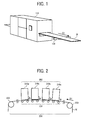
- Fig. 1 is a diagram illustrating an example of entire configuration of a production printer 110 as an image forming apparatus according to an embodiment.
- the production printer 110 is a high-speed printer for use in high-volume printing of 100 pages or more per minute, for example, and is capable of applying ink on a continuous-form recording medium such as continuous-form paper W.
- the continuous-form paper W is conveyed by one or more feed rollers 130 in the direction of arrow D1 in Fig. 1 and fed to the outside of the production printer 110.
- the feed roller 130 performs positioning and tension adjustment of the continuous-form paper W.
- An image forming unit of the production printer 110 is an inkjet type that does printing on the recording medium by discharging ink droplets from ink heads of a plurality of ink head units according to image data.
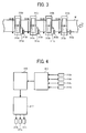
- Fig. 2 is a schematic side cross-sectional view of an example of an image forming unit in the production printer 110. As illustrated in Fig. 2 , the image forming unit of the production printer 110 is provided with a conveyor 201 that holds and conveys the continuous-form paper W to be printed, and a printing unit 202 that executes printing on the continuous-form paper W held and conveyed by the conveyor 201.
- the conveyor 201 is composed of a first drive roller 232, a second drive roller 233, guide rollers 234, and the like. At least one of the first drive roller 232 and the second drive roller 233 is driven for rotation by a drive source such as a motor not illustrated. The tension of the continuous-form paper W is adjusted between the first drive roller 232 and the second drive roller 233.
- the printing unit 202 includes a first head unit 310a, a second head unit 310b, a third head unit 310c, and a fourth head unit 310d that discharge ink droplets.
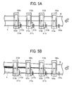
- Fig. 3 is a schematic plan view of an example of the image forming unit in the production printer 110.
- the image forming unit has the first head unit 310a, the second head unit 310b, the third head unit 310c, and the fourth head unit 310d aligned at certain spacing between them in this order from the upstream side of the conveyance direction of the continuous-form paper W (shown by arrow D1 in Fig. 3 ).
- the kinds of ink droplets used in the ink head units For example, ink droplets of black (K), cyan (C), magenta (M), and yellow (Y) may be used in the individual ink head units.
- ink droplets of black (K) may be used at the first head unit 310a
- ink droplets of cyan (C) at the ink head unit 310b may be used at the first head unit 310a
- ink droplets of magenta (M) at the ink head unit 310c may be used at the first head unit 310a
- ink droplets of yellow (Y) may be used at the first head unit 310a
- ink droplets of cyan (C) at the ink head unit 310b may be used at the first head unit 310a
- ink droplets of magenta (M) at the ink head unit 310c may be used at the first head unit 310b
- M magenta
- Y ink droplets of yellow
- the first head unit 310a, the second head unit 310b, the third head unit 310c, and the fourth head unit 310d have ink discharge nozzles 313a, 313b, 313c, and 313d, respectively, as discharge ports for discharging ink droplets.
- the ink head units 310b, 310c, and 310d have actuators 311b, 311c, and 311d for moving the ink head units 310b, 310c, and 310d in a direction (shown by arrows D2 in Fig. 3 ) perpendicular to the conveyance direction of the continuous-form paper W.
- the ink head unit 310a at the most upstream side of the conveyance direction of the continuous-form paper W is set as a reference ink head unit, and the position of the ink head unit 310a in the direction perpendicular to the conveyance direction of the continuous-form paper W is fixed. Accordingly, the ink head unit 310a is not provided with an actuator. Alternatively, as the other ink head units, the ink head unit 310a may be provided with an actuator to move the position of the ink head unit 310a in the direction perpendicular to the conveyance direction of the continuous-form paper W.
- edge sensors 312a, 312b, 312c, and 312d are arranged, respectively, to detect the edge position of the continuous-form paper W perpendicular to the conveyance direction of the continuous-form paper W.
- the positions of the ink head units 310b, 310c, and 310d are corrected. The correction of the positions of the ink head units will be described later in detail.
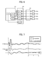
- Fig. 4 is a block diagram illustrating a configuration of a control system that corrects the positions of the ink head units.
- a read controller 410 detects output values from the edge sensors 312a, 312b, 312c, and 312d at every sampling cycle, and converts the same into data from which unnecessary frequency components are removed by filtering (hereinafter, referred to as sensor readings). These sensor readings are saved in a memory 416. The sensor reading from the edge sensor 312a is held in the memory 416 until the edge position of the continuous-form paper W read by the edge sensor 312a passes through the edge sensor 312d. The readings from the edge sensors except for the edge sensor 312a are overwritten as needed.
- a recording-position correction controller 417 performs necessary arithmetic operations on the data saved in the memory 416, and controls the actuators 311b, 311 c, and 311d based on the results of the arithmetic operations.
- Figs. 5A through 5D are illustrations of an overview of correction of the positions of the ink head units. The following description will be given with reference to Fig. 4 as appropriate.
- Fig. 5A for example, no color deviation occurs in printing on the continuous-form paper W when a line linking the ink discharge nozzles 313a, 313b, 313c, and 313d is parallel to a line formed by the edge of the continuous-form paper W.
- the line formed by the edge of the continuous-form paper W in the ideal state with no occurrence of color deviation in printing as described above will be designated as a reference line L.
- the sensor readings of the edge positions of the continuous-form paper W detected by the edge sensors 312a, 312b, 312c, and 312d will be designated as reference values r1, r2, r3, and r4.
- the reference values r1, r2, r3, and r4 vary among the apparatuses and the edge sensors depending on apparatus assembly errors, individual differences among the sensors, and the like. Accordingly, at the time of installation of an apparatus or replacement of edge sensors, it is necessary to make a reference value adjustment for determining reference values described later.
- the sensor reading on the edge sensor 312a when a certain section of the continuous-form paper W (shaded section S in Fig. 5C ) passes through the edge sensor 312a will be designated as p1.
- the recording-position correction controller 417 calculates the difference (deviation d1) between the sensor reading p1 and the reference value r1 on the edge sensor 312a.
- the sensor reading on the edge sensor 312b when the certain section of the continuous-form paper W (shaded section S in Fig. 5D ) passes through the edge sensor 312b will be designated as p2.
- the recording-position correction controller 417 calculates the difference (deviation d2) between the sensor reading p2 and the reference value r2 on the edge sensor 312b.
- the edge positions of the recording medium detected by the edge sensors include errors relative to the actual edge positions.
- the sensor reading p1 and the reference value r1 on the edge sensor 312a are both the values detected by the edge sensor 312a and thus include errors of the same magnitude. Accordingly, the errors are canceled out by taking the difference (deviation d1) between the sensor reading p1 and the reference value r1 on the edge sensor 312a. Similarly, the errors are canceled out by taking the difference (deviation d2) between the sensor reading p2 and the reference value r2 on the edge sensor 312b.
- the read controller 410 determines a relative deviation value D1 by calculating the difference between the positional deviation d1 and the positional deviation d2.
- the relative deviation value D1 represents the relative positional relation between the edge position of the continuous-form paper W at the location of the ink head unit 310b and the edge position of the continuous-form paper W at the location of the ink head unit 310a.
- the errors are canceled out by taking the positional deviation d1 and the positional deviation d2, and thus no error is included in the relative deviation value D1 calculated by the difference between the positional deviation d1 and the positional deviation d2.
- the recording-position correction controller 417 controls the actuator 311b according to the relative deviation value D1 to correct the position of the ink head unit 310b.
- the recording positions of the ink head units 310c and 310d are also corrected by the same method as that for the correction of the recording position of the ink head unit 310b described above. Specifically, the recording-position correction controller 417 calculates relative deviation values D2 and D3 of the edge positions of the continuous-form paper W at the locations of the ink head units 310c and 310d from the edge position of the continuous-form paper W at the location of the ink head unit 310a. Then, the recording-position correction controller 417 controls the actuators 311c and 311d according to the relative deviation values D2 and D3 to correct the positions of the ink head units 310c and 310d.
- the amount of movement of the ink head unit 310a is added to the relative deviation values D1, D2, and D3.
- the sensor readings of the edge positions of the continuous-form paper W detected by the edge sensors 312a, 312b, 312c, and 312d are to be the reference values r1, r2, r3, and r4. It can be automatically determined whether the continuous-form paper W is stably conveyed as described below. Therefore, according to this embodiment, reference value adjustment can be automatically made.
- Fig. 6 is a block diagram illustrating a configuration of a control system that performs a reference-value adjustment operation.
- a reference-value adjustment controller 411 has individual controllers, that is, a K-C controller 412, a K-M controller 413, and a K-Y controller 414, and a general controller 415 that collectively controls the individual controllers.
- the K-C controller 412 reads from the memory 416 the reading p1 on the edge sensor 312a and the reading p2 on the edge sensor 312b, and calculates the difference between these readings to determine whether the continuous-form paper W is stably conveyed.
- the K-C controller 412 determines that the continuous-form paper W is stably conveyed when the calculated difference falls within a prescribed range for a certain period of time.
- the general controller 415 calculates the reference values r1, r2, r3, and r4 from the sensor readings of the edge positions of the continuous-form paper W detected by the edge sensors 312a, 312b, 312c, and 312d, respectively. These reference values r1, r2, r3, and r4 are saved in the memory 416.
- the K-M controller 413 and the K-Y controller 414 determine whether the continuous-form paper W is stably conveyed as the K-C controller 412 does.
- the K-M controller 413 determines whether the continuous-form paper W is stably conveyed by the difference between the reading p1 on the edge sensor 312a and the reading p3 on the edge sensor 312c.
- the K-Y controller 414 determines whether the continuous-form paper W is stably conveyed by the difference between the reading p1 and the reading p4 on the edge sensor 312d.
- Fig. 7 is an illustration of a method for determining the stability of conveyance of continuous-form paper W by the K-Y controller 414.
- the horizontal axis indicates the time and the vertical axis the readings.
- Curves K and Y in Fig. 7 are plots of readings on the edge sensors 312a and 312d, respectively.
- a curve K_Deviation deviates from the curve K by the time determined by dividing the distance between the edge sensor 312a and the edge sensor 312d by the conveyance speed of the continuous-form paper W. This allows the comparison between the readings p1 and p4 of the edge positions detected by the edge sensors 312a and 312d in the same section of the continuous-form paper W.
- By comparing the readings of the edge positions in the same section of the continuous-form paper W it is possible to determine whether the continuous-form paper W is stably conveyed in a more accurate manner.
- a curve Y-K_Deviation constitutes the difference between the curve Y and the curve K_Deviation.
- the curve Y-K_Deviation it is possible to determine the degree of variations in the edge position of the continuous-form paper W between the edge sensor 312a and the edge sensor 312d in the direction perpendicular to the conveyance direction of the continuous-form paper W. That is, it can be said that, when the variations in the curve Y-K_Deviation are large, the continuous-form paper W is unstably conveyed between the edge sensor 312a and the edge sensor 312d. In contrast, it can be said that, when the variations in the curve Y-K_Deviation are small, the continuous-form paper W is stably conveyed between the edge sensor 312a and the edge sensor 312d.
- the K-Y controller 414 determines that the continuous-form paper W is stably conveyed for the period of time indicated by P and Q.
- the curve such as the curve Y-K_Deviation in Fig. 7 will be referred to as "variation curve.”
- the period of time during which the individual controller determines that the continuous-form paper W is stably conveyed such as the period of time T indicated by P and Q in Fig. 7 will be referred to as "individual stable period.”
- the methods for determining the stability of conveyance of the continuous-form paper W by the K-C controller 412 and the K-M controller 413 are the same as the foregoing method for determining the stability of conveyance of the continuous-form paper W by the K-Y controller 414. Specifically, each of the K-C controller 412 and the K-M controller 413 determines that the continuous-form paper W is stably conveyed when the variations in the variation curve fall within a certain range ⁇ ⁇ over the certain time T.
- the general controller 415 illustrated in Fig. 6 determines that the continuous-form paper W is stably conveyed when all of the K-C controller 412, the K-M controller 413, and the K-Y controller 414 have determined that the continuous-form paper W is stably conveyed. That is, the general controller 415 determines that the continuous-form paper W is stably conveyed when all of the individual stable periods at the K-C controller 412, the K-M controller 413, and the K-Y controller 414 overlap.
- the overlapped individual stable periods will be referred to as "overall stable period.”
- the general controller 415 calculates the reference values on the edge sensors based on the sensor readings on the edge sensors during the overall stable period.
- the determinations on the stability of conveyance of the continuous-form paper W by the individual controllers relate to the times required for conveyance of the continuous-form paper W between the edge sensor 312a as a reference and the edge sensors other than the edge sensor 312a. Accordingly, the individual controllers do not provide the results of determination at the same timing on whether the continuous-form paper W is stably conveyed.
- the K-Y controller 414 provides at the latest timing the result of determination on whether the continuous-form paper W is stably conveyed between the edge sensor 312a as a reference and the edge sensor 312d. Therefore, at the timing when the K-Y controller 414 has provided the determination result, the general controller 415 determines whether the continuous-form paper W is stably conveyed.
- the general controller 415 When the general controller 415 provides the determination result indicating that the continuous-form paper W is not stably conveyed, the individual controllers continue to monitor the stability of conveyance of the continuous-form paper W. In case that the general controller 415 provides the determination result indicating that the conveyance is not stable, the K-C controller 412 and the K-M controller 413 start to monitor the next cycle on completion of the previous cycle even while the K-Y controller 414 continues to monitor the previous cycle. When the general controller 415 provides the determination result indicating that the conveyance of the continuous-form paper W is not stable after an elapse of a predetermined time, the controller may instructs displaying an error message.
- the reference values can be calculated as described below, for example.
- the reference value r1 on the edge sensor 312a is calculated by averaging the sensor readings on the edge sensor 312a for the overall stable period.
- Each of the reference values on the edge sensors 312b, 312c, and 312d is calculated by averaging plot values in the differential curve for the overall stable period and adding the reference value r1 on the edge sensor 312a to the averaged value.
- Fig. 8 is a flowchart of an example of a reference-value adjustment control in the control system that performs the reference-value adjustment operation.
- step S1 the conveyance of the continuous-form paper W is started.
- step S2 each of the edge sensors starts to read the edge position of the continuous-form paper W.
- step S3 each of the individual controllers monitors the stability of conveyance of the continuous-form paper W based on the readings on the edge sensors saved in the memory 416. The details of step S3 will be described later.
- the general controller 415 determines whether the continuous-form paper W is stably conveyed according to the results of monitoring for the stability of conveyance of the continuous-form paper W by the individual controllers. When the continuous-form paper W is not stably conveyed (NO at S4), the general controller 415 returns to step S3. When the continuous-form paper W is stably conveyed (YES at S4), the general controller 415 moves to step S5. At step S5, the reference values on the edge sensors are calculated. At step S6, the reference values calculated at step S5 are saved in the memory 416.
- Fig. 9 is a flowchart of an example of a process for determining the stability of conveyance of the continuous-form paper W by the K-C controller 412.
- the K-C controller 412 determines whether an end instruction is received from the general controller 415. When an end instruction is received (YES at S30), the process is terminated. When no end instruction is received (NO at S30), the K-C controller 412 moves to step S31.
- the K-C controller 412 acquires from the memory 416 the latest sensor reading on the edge sensor 312b and the sensor reading on the edge sensor 312a preceding by the time obtained by dividing the distance between the edge sensor 312a and the edge sensor 312b by the conveyance speed.
- the K-C controller 412 calculates the difference between the two sensor readings acquired at step S31.
- the K-C controller 412 adds the value of the difference calculated at step S32 to a summation variable SUM (initial value is 0) and increments a difference data count k (initial value is 0) by 1.
- the K-C controller 412 determines whether the difference data count k is a threshold number or greater. When the difference data count k is smaller than the threshold number (NO at S34), the K-C controller 412 returns to step S30. When the difference data count k is the threshold number or greater (YES at S34), the K-C controller 412 moves to step S35. At step S35, the K-C controller 412 divides the summation variable SUM by the difference data count k to calculate the average of the differences between the two sensor readings acquired at step S31, and sets the difference data count k to the initial value of 0, and then increments an average data count n (initial value is 0) by 1.
- the K-C controller 412 determines whether the average data count n is a threshold number or greater. When the average data count n is smaller than the threshold number (NO at S36), the K-C controller 412 returns to step S30. When the average data count n is the threshold number (YES at S36), the K-C controller 412 moves to step S37.
- the K-C controller 412 uses the average data determined at step S35 to determine whether the continuous-form paper W is stably conveyed. The details of the determination will be described later. When not determining that the conveyance is stable at step S37 (NO at S37), the K-C controller 412 moves to step S38.
- the K-C controller 412 moves to step S39.
- the K-C controller 412 deletes the oldest one of the average values calculated at step S35, and decrements the average data count n by 1, and then returns to step S30.
- the K-C controller 412 sets the average data count n to 0 and moves to step S4 in Fig. 8 .
- Fig. 10 is a diagram describing the details of the determination at step S37 described in Fig. 9 on whether the continuous-form paper W is stably conveyed.
- the vertical axis indicates the average values determined at step S35
- the horizontal axis indicates the cycle numbers of the average values (corresponding to the average data counts n).
- a cycle number of 1 is assigned to the oldest average value, and the following cycle numbers are assigned to the next older average values in order of increasing.
- the number of the average values for use in determination on the stability of conveyance of the continuous-form paper W is five and a threshold range is ⁇ 5 ⁇ m.
- the threshold range is determined based on an allowable deviation range from an average value when color deviations from the average value fall within the range of ⁇ 3 ⁇ .
- the average value with the cycle number 1 is set as a reference value and all of the differences between the average values with the following cycle numbers 2, 3, and 4 and the reference value fall within the range of ⁇ 5 ⁇ m, it is determined that the continuous-form paper W is stably conveyed.
- the method for reference value adjustment described above is a mere example, and the reference value adjustment may not be made by determining whether the continuous-form paper W is stably conveyed with reference to the reading p1 on the edge sensor 312a.
- the stability of the conveyance of the continuous-form paper W may be determined with reference to the reading on the edge sensor other than the edge sensor 312a.
- four ink head units are provided and thus the three individual controllers are used. When the number of the ink head units is increased or decreased, the individual controllers may also be increased or decreased accordingly.
- the method for reference value adjustment is basically the same as the method described above. At the reference value adjustment, conditions are desirably set such the continuous-form paper W travels stably (the kind of the continuous-form paper W, the conveyance speed of the same, and others).
- An image forming apparatus includes: a plurality of head units such as the ink head units 310a, 310b, 310c, and 310d that are arranged side by side with certain spacing therebetween in a conveyance direction of a recording medium and have discharge ports such as the ink discharge nozzles 313a, 313b, 313c, and 313d to discharge droplets, such as ink droplets, on the recording medium; a plurality of edge sensors such as the edge sensors 312a, 312b, 312c, and 312d that are arranged in correspondence with at least two sensor-corresponding head units of the plurality of head units and detect edge positions of the recording medium in a direction perpendicular to the conveyance direction of the recording medium; at least one actuator such as the actuators 311b, 311 c, and 311d to move at least one actuator-driven head unit of the sensor-corresponding head units in the direction perpendicular to the conveyance direction of the recording medium; and a controller such as the recording position correction controller 417 to control the
- the image forming apparatus further includes a memory such as the memory 416 to store data on the edge positions of the recording medium read by the plurality of edge sensors.
- the memory stores in advance reference values on the plurality of edge sensors as readings on the edge sensors of the edge positions of the recording medium as a reference.
- the controller calculates the differences between the edge positions of the recording medium read by the plurality of edge sensors and the reference values on the edge sensors, and uses the differences to control the actuators and correct the positions of the head units having the actuators.
- the edge positions of the recording medium read by the edge sensors include errors resulting from apparatus assembly and individual differences among the edge sensors.
- the edge position of the recording medium read by one edge sensor and the reference value on the edge sensor are values read by the same edge sensor, and thus include an error of the same size.
- the foregoing error can be canceled out by taking the difference between the edge position of the recording medium read by the one edge sensor and the reference value on the edge sensor.
- the difference between the difference in an edge sensor arranged in correspondence with one head unit having an actuator and the difference in an edge sensor arranged in correspondence with another head unit it is possible to determine correctly the relative positional relation between the edge position of the recording medium at the location of the former head unit and the edge position of the recording medium at the location of the latter head unit.
- By correcting the position of the former head unit according to the relative positional relation it is possible to raise correction accuracy and suppress occurrence of a color deviation in printing on the recording medium.
- the controller sets one of the at least one actuator-less head unit to a reference head unit, and when all of the at least two sensor-corresponding head units are actuator-driven head units having the actuator, the controller sets one of the at least two sensor-corresponding head units to the reference head unit.
- the controller determines whether the recording medium is stably conveyed by calculating a difference between an edge position of the recording medium read by at least one of the edge sensors arranged in correspondence with non-reference head units of the actuator-driven head units and an edge position of the recording medium read by an edge sensor of the edge sensors arranged in correspondence with the reference head unit, and determining whether variations in the difference fall within a predetermined threshold value over a predetermined period of time.
- the controller sets the edge position of the recording medium when the recording medium is stably conveyed as the reference edge position of the recording medium. Accordingly, the controller can automatically determine whether the recording medium is stably conveyed by determining whether variations in the difference fall within the predetermined threshold range over a predetermined period of time.
- the reference edge position of the recording medium can be automatically determined. Accordingly, the reference values on the head units can also be automatically set. Such a configuration prevents the user from having to set the reference values when, after the replacement of edge sensors, the reference value is to be re-set on the new head unit.
- the edge sensors are arranged upstream from the sensor-corresponding head units in the conveyance direction of the recording medium.
- any one of the aspects A to C when, on determination of whether the variations in the difference fall within the predetermined threshold range over the predetermined period of time, a determination result indicating that the recording medium is stably conveyed is not obtained after an elapse of a predetermined determination period, an error message is displayed. Accordingly, in the event of occurrence of any abnormality in the recording medium conveyance system, it is possible to prevent the determination on the parallelism from being continued for an unnecessarily long time.
- the threshold range is determined by an allowable deviation amount from an average value of the difference set so that deviations from the average value between colors fall within a range of ⁇ 3 ⁇ .
Landscapes
- Engineering & Computer Science (AREA)
- Quality & Reliability (AREA)
- Ink Jet (AREA)
Abstract
Description
- Embodiments of this disclosure relate to an image forming apparatus that has a line head composed of a plurality of head units.
- Conventionally, there is known an image forming apparatus such as a line-type inkjet printer, for example, that performs printing on a recording medium by discharging ink droplets onto the recording medium from a plurality of head units aligned from upstream to downstream sides in the conveyance direction of the recording medium.
- There is a technique by which to detect data on edge position of a recording medium by edge sensors in the vicinities of a plurality of head units, and correct the positions of the head units according to the edge position data. Specifically, comparison is made between the data on the edge position of the recording medium detected by the edge sensor (upstream edge sensor) arranged in correspondence with the head unit at upstream side of the conveyance direction of the recording medium and the edge sensor (downstream edge sensor) arranged in correspondence with the head unit at the downstream side of the conveyance direction of the recording medium to calculate the relative positional relation between the edge position of the recording medium at the location of the upstream head unit and the edge position of the recording medium at the location of the downstream head unit. Then, according to the relative positional relation, an actuator for moving the head unit at the downstream side of the conveyance direction of the recording medium is controlled to correct the position of the downstream head unit. Accordingly, even when the position of the recording medium varies during its conveyance, the head units can discharge ink droplets to the desired points on the recording medium, thereby suppressing printing failures due to deviation in discharging points of ink droplets.
- Due to apparatus assembly errors and individual differences among the edge sensors, the edge positions of the recording medium detected by the edge sensors may not match the actual edge positions but include a certain degree of error relative to the actual edge positions. According to a technique of
JP-2011-136526-A - When the relative positional relation between the edge position of the recording medium at the location of the upstream head unit and the edge position of the recording medium at the location of the downstream head unit is calculated as described in
JP-2011-136526-A JP-2011-136526-A - In an aspect of the present disclosure, there is provided an image forming apparatus that includes a conveyor, a plurality of head units, a plurality of edge sensors, an actuator, a memory, and a controller. The conveyor conveys a recording medium. The plurality of head units are arranged side by side with certain spacing therebetween in a conveyance direction of the recording medium. The plurality of head units include discharge ports to discharge droplets on the recording medium. The plurality of edge sensors are arranged in correspondence with at least two sensor-corresponding head units of the plurality of head units, to detect edge positions of the recording medium in a direction perpendicular to the conveyance direction of the recording medium. The actuator moves at least one actuator-driven head unit of the at least two sensor-corresponding head units in the direction perpendicular to the conveyance direction of the recording medium. The memory stores reference values generated in advance based on data on the edge positions of the recording medium read by the plurality of edge sensors. The controller controls the actuator according to the edge positions of the recording medium read by the plurality of edge sensors and the reference values to correct a position of the at least one actuator-driven head unit.
- According to this disclosure, a configuration having a plurality of head units aligned over a recording medium from upstream to downstream sides of the conveyance direction of the recording medium makes it possible to suppress occurrence of color deviation in printing on the recording medium.
- The aforementioned and other aspects, features, and advantages of the present disclosure would be better understood by reference to the following detailed description when considered in connection with the accompanying drawings, wherein:
-
Fig. 1 is a diagram illustrating an example of entire configuration of a production printer according to an embodiment; -
Fig. 2 is a schematic side cross-sectional view of an example of an image forming unit in the production printer according to the embodiment; -
Fig. 3 is a schematic plan view of an example of the image forming unit in the production printer according to the embodiment; -
Fig. 4 is a block diagram illustrating a configuration of a control system that corrects the positions of ink head units at the image forming unit according to the embodiment; -
Figs. 5A through 5D are illustrations of an overview of correction of the positions of the ink head units according to the embodiment; -
Fig. 6 is a block diagram illustrating a configuration of a control system that performs a reference-value adjustment operation at the correction of the position of the ink head units according to the embodiment; -
Fig. 7 is an illustration of a method for determining the stability of conveyance of continuous-form paper W by a K-Y controller in the control system that performs the reference-value adjustment operation according to the embodiment; -
Fig. 8 is a flowchart of an example of a reference-value adjustment control in the control system that performs the reference-value adjustment operation according to the embodiment; -
Fig. 9 is a flowchart of an example of a process for determining the stability of conveyance of the continuous-form paper W by a K-C controller in the control system that performs the reference-value adjustment operation according to the embodiment; and -
Fig. 10 is an illustration of details of determination on whether the conveyance of the continuous-form paper W is stabled at step S37 described inFig. 9 according to the embodiment. - The accompanying drawings are intended to depict embodiments of the present disclosure and should not be interpreted to limit the scope thereof. The accompanying drawings are not to be considered as drawn to scale unless explicitly noted.
- In describing embodiments illustrated in the drawings, specific terminology is employed for the sake of clarity. However, the disclosure of this patent specification is not intended to be limited to the specific terminology so selected and it is to be understood that each specific element includes all technical equivalents that operate in a similar manner and achieve similar results.
- Although the embodiments are described with technical limitations with reference to the attached drawings, such description is not intended to limit the scope of the disclosure and all of the components or elements described in the embodiments of this disclosure are not necessarily indispensable.
- Referring now to the drawings, embodiments of the present disclosure are described below. In the drawings for explaining the following embodiments, the same reference codes are allocated to elements (members or components) having the same function or shape and redundant descriptions thereof are omitted below.
-
Fig. 1 is a diagram illustrating an example of entire configuration of aproduction printer 110 as an image forming apparatus according to an embodiment. Theproduction printer 110 is a high-speed printer for use in high-volume printing of 100 pages or more per minute, for example, and is capable of applying ink on a continuous-form recording medium such as continuous-form paper W. The continuous-form paper W is conveyed by one ormore feed rollers 130 in the direction of arrow D1 inFig. 1 and fed to the outside of theproduction printer 110. During the printing operation, thefeed roller 130 performs positioning and tension adjustment of the continuous-form paper W. - An image forming unit of the
production printer 110 is an inkjet type that does printing on the recording medium by discharging ink droplets from ink heads of a plurality of ink head units according to image data.Fig. 2 is a schematic side cross-sectional view of an example of an image forming unit in theproduction printer 110. As illustrated inFig. 2 , the image forming unit of theproduction printer 110 is provided with aconveyor 201 that holds and conveys the continuous-form paper W to be printed, and aprinting unit 202 that executes printing on the continuous-form paper W held and conveyed by theconveyor 201. - The
conveyor 201 is composed of afirst drive roller 232, asecond drive roller 233,guide rollers 234, and the like. At least one of thefirst drive roller 232 and thesecond drive roller 233 is driven for rotation by a drive source such as a motor not illustrated. The tension of the continuous-form paper W is adjusted between thefirst drive roller 232 and thesecond drive roller 233. - The
printing unit 202 includes afirst head unit 310a, asecond head unit 310b, athird head unit 310c, and afourth head unit 310d that discharge ink droplets. -
Fig. 3 is a schematic plan view of an example of the image forming unit in theproduction printer 110. As illustrated inFig. 3 , the image forming unit has thefirst head unit 310a, thesecond head unit 310b, thethird head unit 310c, and thefourth head unit 310d aligned at certain spacing between them in this order from the upstream side of the conveyance direction of the continuous-form paper W (shown by arrow D1 inFig. 3 ). There is no particular limitation on the kinds of ink droplets used in the ink head units. For example, ink droplets of black (K), cyan (C), magenta (M), and yellow (Y) may be used in the individual ink head units. There is also no limitation on which color of ink droplets to be used at which of the ink head units. For example, ink droplets of black (K) may be used at thefirst head unit 310a, ink droplets of cyan (C) at theink head unit 310b, ink droplets of magenta (M) at theink head unit 310c, and ink droplets of yellow (Y) at theink head unit 310d. - The
first head unit 310a, thesecond head unit 310b, thethird head unit 310c, and thefourth head unit 310d haveink discharge nozzles ink head units actuators ink head units Fig. 3 ) perpendicular to the conveyance direction of the continuous-form paper W. In this embodiment, theink head unit 310a at the most upstream side of the conveyance direction of the continuous-form paper W is set as a reference ink head unit, and the position of theink head unit 310a in the direction perpendicular to the conveyance direction of the continuous-form paper W is fixed. Accordingly, theink head unit 310a is not provided with an actuator. Alternatively, as the other ink head units, theink head unit 310a may be provided with an actuator to move the position of theink head unit 310a in the direction perpendicular to the conveyance direction of the continuous-form paper W. - In the vicinities of the
ink head units Fig. 3 ),edge sensors edge sensors ink head units -
Fig. 4 is a block diagram illustrating a configuration of a control system that corrects the positions of the ink head units. Aread controller 410 detects output values from theedge sensors memory 416. The sensor reading from theedge sensor 312a is held in thememory 416 until the edge position of the continuous-form paper W read by theedge sensor 312a passes through theedge sensor 312d. The readings from the edge sensors except for theedge sensor 312a are overwritten as needed. A recording-position correction controller 417 performs necessary arithmetic operations on the data saved in thememory 416, and controls theactuators -
Figs. 5A through 5D are illustrations of an overview of correction of the positions of the ink head units. The following description will be given with reference toFig. 4 as appropriate. As illustrated inFig. 5A , for example, no color deviation occurs in printing on the continuous-form paper W when a line linking theink discharge nozzles edge sensors - As illustrated in
Fig. 5B , if the line formed by the edge of the continuous-form paper W deviates from the reference line L, the line linking theink discharge nozzles - Referring to
Figs. 5C and 5D , a specific method for correcting the positions of the ink head units will be described taking theink head unit 310b as an example. As illustrated inFig. 5C , the sensor reading on theedge sensor 312a when a certain section of the continuous-form paper W (shaded section S inFig. 5C ) passes through theedge sensor 312a will be designated as p1. The recording-position correction controller 417 calculates the difference (deviation d1) between the sensor reading p1 and the reference value r1 on theedge sensor 312a. As illustrated inFig. 5D , the sensor reading on theedge sensor 312b when the certain section of the continuous-form paper W (shaded section S inFig. 5D ) passes through theedge sensor 312b will be designated as p2. The recording-position correction controller 417 calculates the difference (deviation d2) between the sensor reading p2 and the reference value r2 on theedge sensor 312b. - The edge positions of the recording medium detected by the edge sensors include errors relative to the actual edge positions. The sensor reading p1 and the reference value r1 on the
edge sensor 312a are both the values detected by theedge sensor 312a and thus include errors of the same magnitude. Accordingly, the errors are canceled out by taking the difference (deviation d1) between the sensor reading p1 and the reference value r1 on theedge sensor 312a. Similarly, the errors are canceled out by taking the difference (deviation d2) between the sensor reading p2 and the reference value r2 on theedge sensor 312b. - The
read controller 410 determines a relative deviation value D1 by calculating the difference between the positional deviation d1 and the positional deviation d2. The relative deviation value D1 represents the relative positional relation between the edge position of the continuous-form paper W at the location of theink head unit 310b and the edge position of the continuous-form paper W at the location of theink head unit 310a. As described above, the errors are canceled out by taking the positional deviation d1 and the positional deviation d2, and thus no error is included in the relative deviation value D1 calculated by the difference between the positional deviation d1 and the positional deviation d2. The recording-position correction controller 417 controls theactuator 311b according to the relative deviation value D1 to correct the position of theink head unit 310b. - The recording positions of the
ink head units ink head unit 310b described above. Specifically, the recording-position correction controller 417 calculates relative deviation values D2 and D3 of the edge positions of the continuous-form paper W at the locations of theink head units ink head unit 310a. Then, the recording-position correction controller 417 controls theactuators ink head units - When the position of the
ink head unit 310a is movable in the direction perpendicular to the conveyance direction of the continuous-form paper W, the amount of movement of theink head unit 310a is added to the relative deviation values D1, D2, and D3. - Reference value adjustment will be described in outline. It has been experimentally confirmed that, while the continuous-form paper W is stably conveyed, the line linking the
ink discharge nozzles ink discharge nozzles - When it is determined that the continuous-form paper W is stably conveyed, the sensor readings of the edge positions of the continuous-form paper W detected by the
edge sensors -
Fig. 6 is a block diagram illustrating a configuration of a control system that performs a reference-value adjustment operation. A reference-value adjustment controller 411 has individual controllers, that is, aK-C controller 412, aK-M controller 413, and aK-Y controller 414, and ageneral controller 415 that collectively controls the individual controllers. TheK-C controller 412 reads from thememory 416 the reading p1 on theedge sensor 312a and the reading p2 on theedge sensor 312b, and calculates the difference between these readings to determine whether the continuous-form paper W is stably conveyed. TheK-C controller 412 determines that the continuous-form paper W is stably conveyed when the calculated difference falls within a prescribed range for a certain period of time. When it is determined that the continuous-form paper W is stably conveyed, thegeneral controller 415 calculates the reference values r1, r2, r3, and r4 from the sensor readings of the edge positions of the continuous-form paper W detected by theedge sensors memory 416. - The
K-M controller 413 and theK-Y controller 414 determine whether the continuous-form paper W is stably conveyed as theK-C controller 412 does. TheK-M controller 413 determines whether the continuous-form paper W is stably conveyed by the difference between the reading p1 on theedge sensor 312a and the reading p3 on theedge sensor 312c. TheK-Y controller 414 determines whether the continuous-form paper W is stably conveyed by the difference between the reading p1 and the reading p4 on theedge sensor 312d. -
Fig. 7 is an illustration of a method for determining the stability of conveyance of continuous-form paper W by theK-Y controller 414. Referring toFig. 7 , the horizontal axis indicates the time and the vertical axis the readings. Curves K and Y inFig. 7 are plots of readings on theedge sensors edge sensor 312a and theedge sensor 312d by the conveyance speed of the continuous-form paper W. This allows the comparison between the readings p1 and p4 of the edge positions detected by theedge sensors - A curve Y-K_Deviation constitutes the difference between the curve Y and the curve K_Deviation. By the curve Y-K_Deviation, it is possible to determine the degree of variations in the edge position of the continuous-form paper W between the
edge sensor 312a and theedge sensor 312d in the direction perpendicular to the conveyance direction of the continuous-form paper W. That is, it can be said that, when the variations in the curve Y-K_Deviation are large, the continuous-form paper W is unstably conveyed between theedge sensor 312a and theedge sensor 312d. In contrast, it can be said that, when the variations in the curve Y-K_Deviation are small, the continuous-form paper W is stably conveyed between theedge sensor 312a and theedge sensor 312d. - During the period of time between P and Q in
Fig. 7 , the variations in the curve Y-K_Deviation fall within a predetermined range ± α over a predetermined certain time T. Accordingly, theK-Y controller 414 determines that the continuous-form paper W is stably conveyed for the period of time indicated by P and Q. Hereinafter, the curve such as the curve Y-K_Deviation inFig. 7 will be referred to as "variation curve." In addition, the period of time during which the individual controller determines that the continuous-form paper W is stably conveyed such as the period of time T indicated by P and Q inFig. 7 will be referred to as "individual stable period." - The methods for determining the stability of conveyance of the continuous-form paper W by the
K-C controller 412 and theK-M controller 413 are the same as the foregoing method for determining the stability of conveyance of the continuous-form paper W by theK-Y controller 414. Specifically, each of theK-C controller 412 and theK-M controller 413 determines that the continuous-form paper W is stably conveyed when the variations in the variation curve fall within a certain range ± α over the certain time T. - The
general controller 415 illustrated inFig. 6 determines that the continuous-form paper W is stably conveyed when all of theK-C controller 412, theK-M controller 413, and theK-Y controller 414 have determined that the continuous-form paper W is stably conveyed. That is, thegeneral controller 415 determines that the continuous-form paper W is stably conveyed when all of the individual stable periods at theK-C controller 412, theK-M controller 413, and theK-Y controller 414 overlap. Hereinafter, the overlapped individual stable periods will be referred to as "overall stable period." Thegeneral controller 415 calculates the reference values on the edge sensors based on the sensor readings on the edge sensors during the overall stable period. - The determinations on the stability of conveyance of the continuous-form paper W by the individual controllers relate to the times required for conveyance of the continuous-form paper W between the
edge sensor 312a as a reference and the edge sensors other than theedge sensor 312a. Accordingly, the individual controllers do not provide the results of determination at the same timing on whether the continuous-form paper W is stably conveyed. In this embodiment, theK-Y controller 414 provides at the latest timing the result of determination on whether the continuous-form paper W is stably conveyed between theedge sensor 312a as a reference and theedge sensor 312d. Therefore, at the timing when theK-Y controller 414 has provided the determination result, thegeneral controller 415 determines whether the continuous-form paper W is stably conveyed. - When the
general controller 415 provides the determination result indicating that the continuous-form paper W is not stably conveyed, the individual controllers continue to monitor the stability of conveyance of the continuous-form paper W. In case that thegeneral controller 415 provides the determination result indicating that the conveyance is not stable, theK-C controller 412 and theK-M controller 413 start to monitor the next cycle on completion of the previous cycle even while theK-Y controller 414 continues to monitor the previous cycle. When thegeneral controller 415 provides the determination result indicating that the conveyance of the continuous-form paper W is not stable after an elapse of a predetermined time, the controller may instructs displaying an error message. - The reference values can be calculated as described below, for example. The reference value r1 on the
edge sensor 312a is calculated by averaging the sensor readings on theedge sensor 312a for the overall stable period. Each of the reference values on theedge sensors edge sensor 312a to the averaged value. -
Fig. 8 is a flowchart of an example of a reference-value adjustment control in the control system that performs the reference-value adjustment operation. At step S1, the conveyance of the continuous-form paper W is started. At step S2, each of the edge sensors starts to read the edge position of the continuous-form paper W At step S3, each of the individual controllers monitors the stability of conveyance of the continuous-form paper W based on the readings on the edge sensors saved in thememory 416. The details of step S3 will be described later. - At step S4, the
general controller 415 determines whether the continuous-form paper W is stably conveyed according to the results of monitoring for the stability of conveyance of the continuous-form paper W by the individual controllers. When the continuous-form paper W is not stably conveyed (NO at S4), thegeneral controller 415 returns to step S3. When the continuous-form paper W is stably conveyed (YES at S4), thegeneral controller 415 moves to step S5. At step S5, the reference values on the edge sensors are calculated. At step S6, the reference values calculated at step S5 are saved in thememory 416. - The operation at step S3 in
Fig. 8 will be described taking an example of the operation in theK-C controller 412 as an example. TheK-M controller 413 and theK-Y controller 414 perform basically the same operation as that of theK-C controller 412.Fig. 9 is a flowchart of an example of a process for determining the stability of conveyance of the continuous-form paper W by theK-C controller 412. At step S30, theK-C controller 412 determines whether an end instruction is received from thegeneral controller 415. When an end instruction is received (YES at S30), the process is terminated. When no end instruction is received (NO at S30), theK-C controller 412 moves to step S31. At step S31, theK-C controller 412 acquires from thememory 416 the latest sensor reading on theedge sensor 312b and the sensor reading on theedge sensor 312a preceding by the time obtained by dividing the distance between theedge sensor 312a and theedge sensor 312b by the conveyance speed. At step S32, theK-C controller 412 calculates the difference between the two sensor readings acquired at step S31. At step S33, theK-C controller 412 adds the value of the difference calculated at step S32 to a summation variable SUM (initial value is 0) and increments a difference data count k (initial value is 0) by 1. - At step S34, the
K-C controller 412 determines whether the difference data count k is a threshold number or greater. When the difference data count k is smaller than the threshold number (NO at S34), theK-C controller 412 returns to step S30. When the difference data count k is the threshold number or greater (YES at S34), theK-C controller 412 moves to step S35. At step S35, theK-C controller 412 divides the summation variable SUM by the difference data count k to calculate the average of the differences between the two sensor readings acquired at step S31, and sets the difference data count k to the initial value of 0, and then increments an average data count n (initial value is 0) by 1. - At step S36, the
K-C controller 412 determines whether the average data count n is a threshold number or greater. When the average data count n is smaller than the threshold number (NO at S36), theK-C controller 412 returns to step S30. When the average data count n is the threshold number (YES at S36), theK-C controller 412 moves to step S37. At step S37, theK-C controller 412 uses the average data determined at step S35 to determine whether the continuous-form paper W is stably conveyed. The details of the determination will be described later. When not determining that the conveyance is stable at step S37 (NO at S37), theK-C controller 412 moves to step S38. When determining that the conveyance of the continuous-form paper W is stable at step S37 (YES at S37), theK-C controller 412 moves to step S39. At step S38, theK-C controller 412 deletes the oldest one of the average values calculated at step S35, and decrements the average data count n by 1, and then returns to step S30. At step S39, theK-C controller 412 sets the average data count n to 0 and moves to step S4 inFig. 8 . -
Fig. 10 is a diagram describing the details of the determination at step S37 described inFig. 9 on whether the continuous-form paper W is stably conveyed. Referring toFig. 10 , the vertical axis indicates the average values determined at step S35, and the horizontal axis indicates the cycle numbers of the average values (corresponding to the average data counts n). A cycle number of 1 is assigned to the oldest average value, and the following cycle numbers are assigned to the next older average values in order of increasing. In this embodiment, the number of the average values for use in determination on the stability of conveyance of the continuous-form paper W is five and a threshold range is ±5µm. The threshold range is determined based on an allowable deviation range from an average value when color deviations from the average value fall within the range of ±3σ. When the average value with thecycle number 1 is set as a reference value and all of the differences between the average values with the followingcycle numbers - The method for reference value adjustment described above is a mere example, and the reference value adjustment may not be made by determining whether the continuous-form paper W is stably conveyed with reference to the reading p1 on the
edge sensor 312a. Alternatively, the stability of the conveyance of the continuous-form paper W may be determined with reference to the reading on the edge sensor other than theedge sensor 312a. In addition, in this embodiment, four ink head units are provided and thus the three individual controllers are used. When the number of the ink head units is increased or decreased, the individual controllers may also be increased or decreased accordingly. In this case, the method for reference value adjustment is basically the same as the method described above. At the reference value adjustment, conditions are desirably set such the continuous-form paper W travels stably (the kind of the continuous-form paper W, the conveyance speed of the same, and others). - The embodiment described above is a mere example, and the present disclosure produces specific advantages in the following aspects:
- An image forming apparatus includes: a plurality of head units such as the
ink head units ink discharge nozzles edge sensors actuators position correction controller 417 to control the at least one actuator. The image forming apparatus further includes a memory such as thememory 416 to store data on the edge positions of the recording medium read by the plurality of edge sensors. The memory stores in advance reference values on the plurality of edge sensors as readings on the edge sensors of the edge positions of the recording medium as a reference. The controller calculates the differences between the edge positions of the recording medium read by the plurality of edge sensors and the reference values on the edge sensors, and uses the differences to control the actuators and correct the positions of the head units having the actuators. The edge positions of the recording medium read by the edge sensors include errors resulting from apparatus assembly and individual differences among the edge sensors. The edge position of the recording medium read by one edge sensor and the reference value on the edge sensor are values read by the same edge sensor, and thus include an error of the same size. Accordingly, the foregoing error can be canceled out by taking the difference between the edge position of the recording medium read by the one edge sensor and the reference value on the edge sensor. By taking the difference between the difference in an edge sensor arranged in correspondence with one head unit having an actuator and the difference in an edge sensor arranged in correspondence with another head unit, it is possible to determine correctly the relative positional relation between the edge position of the recording medium at the location of the former head unit and the edge position of the recording medium at the location of the latter head unit. By correcting the position of the former head unit according to the relative positional relation, it is possible to raise correction accuracy and suppress occurrence of a color deviation in printing on the recording medium. - In the aspect A, when the sensor-corresponding head units include at least one actuator-less heat unit not having the actuator, the controller sets one of the at least one actuator-less head unit to a reference head unit, and when all of the at least two sensor-corresponding head units are actuator-driven head units having the actuator, the controller sets one of the at least two sensor-corresponding head units to the reference head unit. The controller determines whether the recording medium is stably conveyed by calculating a difference between an edge position of the recording medium read by at least one of the edge sensors arranged in correspondence with non-reference head units of the actuator-driven head units and an edge position of the recording medium read by an edge sensor of the edge sensors arranged in correspondence with the reference head unit, and determining whether variations in the difference fall within a predetermined threshold value over a predetermined period of time. The controller sets the edge position of the recording medium when the recording medium is stably conveyed as the reference edge position of the recording medium. Accordingly, the controller can automatically determine whether the recording medium is stably conveyed by determining whether variations in the difference fall within the predetermined threshold range over a predetermined period of time. It has been experimentally confirmed that, when the recording medium is stably conveyed, no color deviation occurs in printing on the recording medium. By setting the edge position of the recording medium when the recording medium is stably conveyed as a reference edge position of the recording medium, the reference edge position of the recording medium can be automatically determined. Accordingly, the reference values on the head units can also be automatically set. Such a configuration prevents the user from having to set the reference values when, after the replacement of edge sensors, the reference value is to be re-set on the new head unit.
- In the aspect A or B, the edge sensors are arranged upstream from the sensor-corresponding head units in the conveyance direction of the recording medium.
- In any one of the aspects A to C, when, on determination of whether the variations in the difference fall within the predetermined threshold range over the predetermined period of time, a determination result indicating that the recording medium is stably conveyed is not obtained after an elapse of a predetermined determination period, an error message is displayed. Accordingly, in the event of occurrence of any abnormality in the recording medium conveyance system, it is possible to prevent the determination on the parallelism from being continued for an unnecessarily long time.
- In any one of the aspects A to D, the threshold range is determined by an allowable deviation amount from an average value of the difference set so that deviations from the average value between colors fall within a range of ±3σ.
Claims (5)
- An image forming apparatus, comprising:a conveyor (201) to convey a recording medium;a plurality of head units (310a, 310b, 310c, 310d) arranged side by side with certain spacing therebetween in a conveyance direction of the recording medium, the plurality of head units including discharge ports (313a, 313b, 313c, 313d) to discharge droplets on the recording medium;a plurality of edge sensors (312a, 312b, 312c, 312d) arranged in correspondence with at least two sensor-corresponding head units of the plurality of head units, to detect edge positions of the recording medium in a direction perpendicular to the conveyance direction of the recording medium;an actuator (311b, 311c, 311d) to move at least one actuator-driven head unit of the at least two sensor-corresponding head units in the direction perpendicular to the conveyance direction of the recording medium;a memory (416) to store reference values generated in advance based on data on the edge positions of the recording medium read by the plurality of edge sensors; anda controller (417) to control the actuator according to the edge positions of the recording medium read by the plurality of edge sensors and the reference values to correct a position of the at least one actuator-driven head unit.
- The image forming apparatus according to claim 1, wherein when the at least two sensor-corresponding head units include at least one actuator-less heat unit not having the actuator, the controller sets one of the at least one actuator-less head unit to a reference head unit,
wherein, when all of the at least two sensor-corresponding head units are actuator-driven head units having the actuator, the controller sets one of the at least two sensor-corresponding head units to the reference head unit, and
wherein the controller determines whether the recording medium is stably conveyed by calculating a difference between an edge position of the recording medium read by at least one edge sensor of the plurality of edge sensors arranged in correspondence with at least one non-reference head unit of the actuator-driven head units and an edge position of the recording medium read by an edge sensor of the plurality of edge sensors arranged in correspondence with the reference head unit, and determining whether variations in the difference fall within a predetermined threshold range over a predetermined period of time, and
the controller sets the edge positions of the recording medium read when the recording medium is stably conveyed, to reference edge positions of the recording medium. - The image forming apparatus according to claim 1 or 2, wherein the plurality of edge sensors are arranged upstream from the at least two sensor-corresponding head units in the conveyance direction of the recording medium.
- The image forming apparatus according to any one of claims 1 to 3, wherein, when on determination of whether variations in the difference fall within a predetermined threshold range over a predetermined period of time, a determination result indicating that the recording medium is stably conveyed is not obtained after an elapse of a predetermined determination period, the controller instructs displaying an error message.
- The image forming apparatus according to any one of claims 1 to 4, wherein the threshold range is determined based on an allowable deviation amount from an average value of the difference set so that deviations from the average value fall within a range of ±3σ.
Applications Claiming Priority (1)
| Application Number | Priority Date | Filing Date | Title |
|---|---|---|---|
| JP2014221101A JP6418492B2 (en) | 2014-10-30 | 2014-10-30 | Image forming apparatus |
Publications (3)
| Publication Number | Publication Date |
|---|---|
| EP3034308A2 true EP3034308A2 (en) | 2016-06-22 |
| EP3034308A3 EP3034308A3 (en) | 2016-08-24 |
| EP3034308B1 EP3034308B1 (en) | 2019-02-27 |
Family
ID=54360263
Family Applications (1)
| Application Number | Title | Priority Date | Filing Date |
|---|---|---|---|
| EP15191552.7A Active EP3034308B1 (en) | 2014-10-30 | 2015-10-27 | Image forming apparatus |
Country Status (2)
| Country | Link |
|---|---|
| EP (1) | EP3034308B1 (en) |
| JP (1) | JP6418492B2 (en) |
Cited By (2)
| Publication number | Priority date | Publication date | Assignee | Title |
|---|---|---|---|---|
| EP3275675A1 (en) * | 2016-07-26 | 2018-01-31 | Ricoh Company, Ltd. | Apparatus to perform operation on conveyed object |
| CN108621589A (en) * | 2017-03-24 | 2018-10-09 | 株式会社斯库林集团 | Substrate processing apparatus and detection method |
Families Citing this family (3)
| Publication number | Priority date | Publication date | Assignee | Title |
|---|---|---|---|---|
| JP2017211315A (en) * | 2016-05-26 | 2017-11-30 | 株式会社リコー | Conveyed object detection apparatus, apparatus for discharging liquid, conveyed object detection method, and program |
| JP7010074B2 (en) * | 2017-03-15 | 2022-01-26 | 株式会社リコー | Image forming apparatus, image forming system and processing position moving method |
| JP7119453B2 (en) * | 2017-03-21 | 2022-08-17 | 株式会社リコー | Conveying device, conveying system, and timing adjustment method |
Citations (1)
| Publication number | Priority date | Publication date | Assignee | Title |
|---|---|---|---|---|
| JP2011136526A (en) | 2009-12-29 | 2011-07-14 | Seiko Epson Corp | Recording position correction apparatus, control program thereof, control method thereof and recorder |
Family Cites Families (5)
| Publication number | Priority date | Publication date | Assignee | Title |
|---|---|---|---|---|
| JP3400603B2 (en) * | 1995-04-28 | 2003-04-28 | セイコープレシジョン株式会社 | Printer device |
| JP2006181728A (en) * | 2004-12-24 | 2006-07-13 | Canon Finetech Inc | Recording apparatus, recording method and method of correcting recording data |
| JP5444838B2 (en) * | 2008-11-04 | 2014-03-19 | セイコーエプソン株式会社 | Recording position correction apparatus, recording apparatus, and recording position correction method |
| JP4985616B2 (en) * | 2008-11-04 | 2012-07-25 | ブラザー工業株式会社 | Inkjet recording device |
| US9028027B2 (en) * | 2013-07-02 | 2015-05-12 | Ricoh Company, Ltd. | Alignment of printheads in printing systems |
-
2014
- 2014-10-30 JP JP2014221101A patent/JP6418492B2/en active Active
-
2015
- 2015-10-27 EP EP15191552.7A patent/EP3034308B1/en active Active
Patent Citations (1)
| Publication number | Priority date | Publication date | Assignee | Title |
|---|---|---|---|---|
| JP2011136526A (en) | 2009-12-29 | 2011-07-14 | Seiko Epson Corp | Recording position correction apparatus, control program thereof, control method thereof and recorder |
Cited By (3)
| Publication number | Priority date | Publication date | Assignee | Title |
|---|---|---|---|---|
| EP3275675A1 (en) * | 2016-07-26 | 2018-01-31 | Ricoh Company, Ltd. | Apparatus to perform operation on conveyed object |
| CN108621589A (en) * | 2017-03-24 | 2018-10-09 | 株式会社斯库林集团 | Substrate processing apparatus and detection method |
| US10479116B2 (en) | 2017-03-24 | 2019-11-19 | SCREEN Holdings Co., Ltd. | Base material processing apparatus and detection method |
Also Published As
| Publication number | Publication date |
|---|---|
| EP3034308A3 (en) | 2016-08-24 |
| JP6418492B2 (en) | 2018-11-07 |
| JP2016087807A (en) | 2016-05-23 |
| EP3034308B1 (en) | 2019-02-27 |
Similar Documents
| Publication | Publication Date | Title |
|---|---|---|
| US10427423B2 (en) | Recording device discharge position adjustor and image forming apparatus incorporating same | |
| EP3034308B1 (en) | Image forming apparatus | |
| EP3020555B1 (en) | Alignment of printheads in printing systems | |
| US9440431B2 (en) | Inkjet recording apparatus | |
| JP6417858B2 (en) | Recording apparatus and recording apparatus control method | |
| US8998516B2 (en) | Tandem printing system having a web transport controller with a derived drum diameter | |
| US20160114576A1 (en) | Recording position control device and abnormality detecting method for same | |
| US20080073832A1 (en) | Correction method of transport amount and medium transport apparatus | |
| JP6835630B2 (en) | Sheet-fed printing press with sensor system, how to calibrate the sensor system and how to adjust the sensor system | |
| WO2016029925A1 (en) | Determining an alignment characteristic | |
| US6688721B1 (en) | Misalignment reduction of stationary fluid ejector assemblies along axis along which media moves | |
| EP3351387B1 (en) | Inkjet recording device and ink-discharge adjustment method for inkjet recording device | |
| US6773086B2 (en) | Misalignment reduction of staggered fluid ejector assemblies along axis along which assemblies are positioned | |
| JP6390958B2 (en) | Recording unit discharge position adjusting apparatus and image forming apparatus | |
| US9764560B2 (en) | Liquid ejecting apparatus and transport amount adjusting method | |
| US9704076B2 (en) | Rotary encoder correcting method for a transport apparatus, and a transport apparatus using same | |
| JP6247091B2 (en) | Printing position correction method for printing apparatus and printing apparatus | |
| JP6610031B2 (en) | Inkjet recording device | |
| US11772392B2 (en) | Base material processing apparatus and detection method | |
| JP6519843B2 (en) | Recording unit discharge position adjustment device, image forming apparatus, and recording unit position correction method | |
| WO2014005608A1 (en) | Inkjet printer | |
| JP7757853B2 (en) | Belt conveying device, control method for belt conveying device, and inkjet recording device | |
| US10035344B2 (en) | Printing apparatus and printing method | |
| JP7501389B2 (en) | Inkjet recording apparatus and ink ejection control method | |
| JP2020139995A (en) | Image forming device |
Legal Events
| Date | Code | Title | Description |
|---|---|---|---|
| PUAI | Public reference made under article 153(3) epc to a published international application that has entered the european phase |
Free format text: ORIGINAL CODE: 0009012 |
|
| 17P | Request for examination filed |
Effective date: 20151027 |
|
| AK | Designated contracting states |
Kind code of ref document: A2 Designated state(s): AL AT BE BG CH CY CZ DE DK EE ES FI FR GB GR HR HU IE IS IT LI LT LU LV MC MK MT NL NO PL PT RO RS SE SI SK SM TR |
|
| AX | Request for extension of the european patent |
Extension state: BA ME |
|
| PUAL | Search report despatched |
Free format text: ORIGINAL CODE: 0009013 |
|
| AK | Designated contracting states |
Kind code of ref document: A3 Designated state(s): AL AT BE BG CH CY CZ DE DK EE ES FI FR GB GR HR HU IE IS IT LI LT LU LV MC MK MT NL NO PL PT RO RS SE SI SK SM TR |
|
| AX | Request for extension of the european patent |
Extension state: BA ME |
|
| RIC1 | Information provided on ipc code assigned before grant |
Ipc: B41J 11/00 20060101AFI20160720BHEP Ipc: B41J 25/00 20060101ALI20160720BHEP Ipc: B41J 2/21 20060101ALI20160720BHEP |
|
| STAA | Information on the status of an ep patent application or granted ep patent |
Free format text: STATUS: EXAMINATION IS IN PROGRESS |
|
| 17Q | First examination report despatched |
Effective date: 20170512 |
|
| GRAP | Despatch of communication of intention to grant a patent |
Free format text: ORIGINAL CODE: EPIDOSNIGR1 |
|
| STAA | Information on the status of an ep patent application or granted ep patent |
Free format text: STATUS: GRANT OF PATENT IS INTENDED |
|
| INTG | Intention to grant announced |
Effective date: 20181004 |
|
| GRAS | Grant fee paid |
Free format text: ORIGINAL CODE: EPIDOSNIGR3 |
|
| GRAA | (expected) grant |
Free format text: ORIGINAL CODE: 0009210 |
|
| STAA | Information on the status of an ep patent application or granted ep patent |
Free format text: STATUS: THE PATENT HAS BEEN GRANTED |
|
| AK | Designated contracting states |
Kind code of ref document: B1 Designated state(s): AL AT BE BG CH CY CZ DE DK EE ES FI FR GB GR HR HU IE IS IT LI LT LU LV MC MK MT NL NO PL PT RO RS SE SI SK SM TR |
|
| REG | Reference to a national code |
Ref country code: GB Ref legal event code: FG4D |
|
| REG | Reference to a national code |
Ref country code: CH Ref legal event code: EP |
|
| REG | Reference to a national code |
Ref country code: AT Ref legal event code: REF Ref document number: 1100764 Country of ref document: AT Kind code of ref document: T Effective date: 20190315 |
|
| REG | Reference to a national code |
Ref country code: IE Ref legal event code: FG4D |
|
| REG | Reference to a national code |
Ref country code: DE Ref legal event code: R096 Ref document number: 602015025265 Country of ref document: DE |
|
| REG | Reference to a national code |
Ref country code: NL Ref legal event code: MP Effective date: 20190227 |
|
| REG | Reference to a national code |
Ref country code: LT Ref legal event code: MG4D |
|
| PG25 | Lapsed in a contracting state [announced via postgrant information from national office to epo] |
Ref country code: LT Free format text: LAPSE BECAUSE OF FAILURE TO SUBMIT A TRANSLATION OF THE DESCRIPTION OR TO PAY THE FEE WITHIN THE PRESCRIBED TIME-LIMIT Effective date: 20190227 Ref country code: FI Free format text: LAPSE BECAUSE OF FAILURE TO SUBMIT A TRANSLATION OF THE DESCRIPTION OR TO PAY THE FEE WITHIN THE PRESCRIBED TIME-LIMIT Effective date: 20190227 Ref country code: PT Free format text: LAPSE BECAUSE OF FAILURE TO SUBMIT A TRANSLATION OF THE DESCRIPTION OR TO PAY THE FEE WITHIN THE PRESCRIBED TIME-LIMIT Effective date: 20190627 Ref country code: SE Free format text: LAPSE BECAUSE OF FAILURE TO SUBMIT A TRANSLATION OF THE DESCRIPTION OR TO PAY THE FEE WITHIN THE PRESCRIBED TIME-LIMIT Effective date: 20190227 Ref country code: NO Free format text: LAPSE BECAUSE OF FAILURE TO SUBMIT A TRANSLATION OF THE DESCRIPTION OR TO PAY THE FEE WITHIN THE PRESCRIBED TIME-LIMIT Effective date: 20190527 |
|
| PG25 | Lapsed in a contracting state [announced via postgrant information from national office to epo] |
Ref country code: BG Free format text: LAPSE BECAUSE OF FAILURE TO SUBMIT A TRANSLATION OF THE DESCRIPTION OR TO PAY THE FEE WITHIN THE PRESCRIBED TIME-LIMIT Effective date: 20190527 Ref country code: GR Free format text: LAPSE BECAUSE OF FAILURE TO SUBMIT A TRANSLATION OF THE DESCRIPTION OR TO PAY THE FEE WITHIN THE PRESCRIBED TIME-LIMIT Effective date: 20190528 Ref country code: LV Free format text: LAPSE BECAUSE OF FAILURE TO SUBMIT A TRANSLATION OF THE DESCRIPTION OR TO PAY THE FEE WITHIN THE PRESCRIBED TIME-LIMIT Effective date: 20190227 Ref country code: IS Free format text: LAPSE BECAUSE OF FAILURE TO SUBMIT A TRANSLATION OF THE DESCRIPTION OR TO PAY THE FEE WITHIN THE PRESCRIBED TIME-LIMIT Effective date: 20190627 Ref country code: NL Free format text: LAPSE BECAUSE OF FAILURE TO SUBMIT A TRANSLATION OF THE DESCRIPTION OR TO PAY THE FEE WITHIN THE PRESCRIBED TIME-LIMIT Effective date: 20190227 Ref country code: HR Free format text: LAPSE BECAUSE OF FAILURE TO SUBMIT A TRANSLATION OF THE DESCRIPTION OR TO PAY THE FEE WITHIN THE PRESCRIBED TIME-LIMIT Effective date: 20190227 Ref country code: RS Free format text: LAPSE BECAUSE OF FAILURE TO SUBMIT A TRANSLATION OF THE DESCRIPTION OR TO PAY THE FEE WITHIN THE PRESCRIBED TIME-LIMIT Effective date: 20190227 |
|
| REG | Reference to a national code |
Ref country code: AT Ref legal event code: MK05 Ref document number: 1100764 Country of ref document: AT Kind code of ref document: T Effective date: 20190227 |
|
| PG25 | Lapsed in a contracting state [announced via postgrant information from national office to epo] |
Ref country code: CZ Free format text: LAPSE BECAUSE OF FAILURE TO SUBMIT A TRANSLATION OF THE DESCRIPTION OR TO PAY THE FEE WITHIN THE PRESCRIBED TIME-LIMIT Effective date: 20190227 Ref country code: AL Free format text: LAPSE BECAUSE OF FAILURE TO SUBMIT A TRANSLATION OF THE DESCRIPTION OR TO PAY THE FEE WITHIN THE PRESCRIBED TIME-LIMIT Effective date: 20190227 Ref country code: RO Free format text: LAPSE BECAUSE OF FAILURE TO SUBMIT A TRANSLATION OF THE DESCRIPTION OR TO PAY THE FEE WITHIN THE PRESCRIBED TIME-LIMIT Effective date: 20190227 Ref country code: SK Free format text: LAPSE BECAUSE OF FAILURE TO SUBMIT A TRANSLATION OF THE DESCRIPTION OR TO PAY THE FEE WITHIN THE PRESCRIBED TIME-LIMIT Effective date: 20190227 Ref country code: ES Free format text: LAPSE BECAUSE OF FAILURE TO SUBMIT A TRANSLATION OF THE DESCRIPTION OR TO PAY THE FEE WITHIN THE PRESCRIBED TIME-LIMIT Effective date: 20190227 Ref country code: EE Free format text: LAPSE BECAUSE OF FAILURE TO SUBMIT A TRANSLATION OF THE DESCRIPTION OR TO PAY THE FEE WITHIN THE PRESCRIBED TIME-LIMIT Effective date: 20190227 Ref country code: IT Free format text: LAPSE BECAUSE OF FAILURE TO SUBMIT A TRANSLATION OF THE DESCRIPTION OR TO PAY THE FEE WITHIN THE PRESCRIBED TIME-LIMIT Effective date: 20190227 Ref country code: DK Free format text: LAPSE BECAUSE OF FAILURE TO SUBMIT A TRANSLATION OF THE DESCRIPTION OR TO PAY THE FEE WITHIN THE PRESCRIBED TIME-LIMIT Effective date: 20190227 |
|
| REG | Reference to a national code |
Ref country code: DE Ref legal event code: R097 Ref document number: 602015025265 Country of ref document: DE |
|
| PG25 | Lapsed in a contracting state [announced via postgrant information from national office to epo] |
Ref country code: PL Free format text: LAPSE BECAUSE OF FAILURE TO SUBMIT A TRANSLATION OF THE DESCRIPTION OR TO PAY THE FEE WITHIN THE PRESCRIBED TIME-LIMIT Effective date: 20190227 Ref country code: SM Free format text: LAPSE BECAUSE OF FAILURE TO SUBMIT A TRANSLATION OF THE DESCRIPTION OR TO PAY THE FEE WITHIN THE PRESCRIBED TIME-LIMIT Effective date: 20190227 |
|
| PG25 | Lapsed in a contracting state [announced via postgrant information from national office to epo] |
Ref country code: AT Free format text: LAPSE BECAUSE OF FAILURE TO SUBMIT A TRANSLATION OF THE DESCRIPTION OR TO PAY THE FEE WITHIN THE PRESCRIBED TIME-LIMIT Effective date: 20190227 |
|
| PLBE | No opposition filed within time limit |
Free format text: ORIGINAL CODE: 0009261 |
|
| STAA | Information on the status of an ep patent application or granted ep patent |
Free format text: STATUS: NO OPPOSITION FILED WITHIN TIME LIMIT |
|
| 26N | No opposition filed |
Effective date: 20191128 |
|
| PG25 | Lapsed in a contracting state [announced via postgrant information from national office to epo] |
Ref country code: SI Free format text: LAPSE BECAUSE OF FAILURE TO SUBMIT A TRANSLATION OF THE DESCRIPTION OR TO PAY THE FEE WITHIN THE PRESCRIBED TIME-LIMIT Effective date: 20190227 |
|
| PG25 | Lapsed in a contracting state [announced via postgrant information from national office to epo] |
Ref country code: TR Free format text: LAPSE BECAUSE OF FAILURE TO SUBMIT A TRANSLATION OF THE DESCRIPTION OR TO PAY THE FEE WITHIN THE PRESCRIBED TIME-LIMIT Effective date: 20190227 |
|
| PG25 | Lapsed in a contracting state [announced via postgrant information from national office to epo] |
Ref country code: MC Free format text: LAPSE BECAUSE OF FAILURE TO SUBMIT A TRANSLATION OF THE DESCRIPTION OR TO PAY THE FEE WITHIN THE PRESCRIBED TIME-LIMIT Effective date: 20190227 |
|
| REG | Reference to a national code |
Ref country code: CH Ref legal event code: PL |
|
| PG25 | Lapsed in a contracting state [announced via postgrant information from national office to epo] |
Ref country code: CH Free format text: LAPSE BECAUSE OF NON-PAYMENT OF DUE FEES Effective date: 20191031 Ref country code: LU Free format text: LAPSE BECAUSE OF NON-PAYMENT OF DUE FEES Effective date: 20191027 Ref country code: LI Free format text: LAPSE BECAUSE OF NON-PAYMENT OF DUE FEES Effective date: 20191031 |
|
| REG | Reference to a national code |
Ref country code: BE Ref legal event code: MM Effective date: 20191031 |
|
| PG25 | Lapsed in a contracting state [announced via postgrant information from national office to epo] |
Ref country code: BE Free format text: LAPSE BECAUSE OF NON-PAYMENT OF DUE FEES Effective date: 20191031 |
|
| PG25 | Lapsed in a contracting state [announced via postgrant information from national office to epo] |
Ref country code: IE Free format text: LAPSE BECAUSE OF NON-PAYMENT OF DUE FEES Effective date: 20191027 |
|
| PG25 | Lapsed in a contracting state [announced via postgrant information from national office to epo] |
Ref country code: CY Free format text: LAPSE BECAUSE OF FAILURE TO SUBMIT A TRANSLATION OF THE DESCRIPTION OR TO PAY THE FEE WITHIN THE PRESCRIBED TIME-LIMIT Effective date: 20190227 |
|
| PG25 | Lapsed in a contracting state [announced via postgrant information from national office to epo] |
Ref country code: MT Free format text: LAPSE BECAUSE OF FAILURE TO SUBMIT A TRANSLATION OF THE DESCRIPTION OR TO PAY THE FEE WITHIN THE PRESCRIBED TIME-LIMIT Effective date: 20190227 Ref country code: HU Free format text: LAPSE BECAUSE OF FAILURE TO SUBMIT A TRANSLATION OF THE DESCRIPTION OR TO PAY THE FEE WITHIN THE PRESCRIBED TIME-LIMIT; INVALID AB INITIO Effective date: 20151027 |
|
| PG25 | Lapsed in a contracting state [announced via postgrant information from national office to epo] |
Ref country code: MK Free format text: LAPSE BECAUSE OF FAILURE TO SUBMIT A TRANSLATION OF THE DESCRIPTION OR TO PAY THE FEE WITHIN THE PRESCRIBED TIME-LIMIT Effective date: 20190227 |
|
| P01 | Opt-out of the competence of the unified patent court (upc) registered |
Effective date: 20230522 |
|
| PGFP | Annual fee paid to national office [announced via postgrant information from national office to epo] |
Ref country code: DE Payment date: 20241021 Year of fee payment: 10 |
|
| PGFP | Annual fee paid to national office [announced via postgrant information from national office to epo] |
Ref country code: GB Payment date: 20241025 Year of fee payment: 10 |
|
| PGFP | Annual fee paid to national office [announced via postgrant information from national office to epo] |
Ref country code: FR Payment date: 20241021 Year of fee payment: 10 |