EP3033461B1 - Horizontaler primär- und zwischennivellierer - Google Patents
Horizontaler primär- und zwischennivellierer Download PDFInfo
- Publication number
- EP3033461B1 EP3033461B1 EP14836733.7A EP14836733A EP3033461B1 EP 3033461 B1 EP3033461 B1 EP 3033461B1 EP 14836733 A EP14836733 A EP 14836733A EP 3033461 B1 EP3033461 B1 EP 3033461B1
- Authority
- EP
- European Patent Office
- Prior art keywords
- lower frame
- wall
- upper frame
- bolt
- architectural
- Prior art date
- Legal status (The legal status is an assumption and is not a legal conclusion. Google has not performed a legal analysis and makes no representation as to the accuracy of the status listed.)
- Not-in-force
Links
Images



Classifications
-
- E—FIXED CONSTRUCTIONS
- E04—BUILDING
- E04F—FINISHING WORK ON BUILDINGS, e.g. STAIRS, FLOORS
- E04F21/00—Implements for finishing work on buildings
- E04F21/18—Implements for finishing work on buildings for setting wall or ceiling slabs or plates
- E04F21/1838—Implements for finishing work on buildings for setting wall or ceiling slabs or plates for setting a plurality of similar elements
- E04F21/1877—Leveling devices
-
- E—FIXED CONSTRUCTIONS
- E04—BUILDING
- E04B—GENERAL BUILDING CONSTRUCTIONS; WALLS, e.g. PARTITIONS; ROOFS; FLOORS; CEILINGS; INSULATION OR OTHER PROTECTION OF BUILDINGS
- E04B2/00—Walls, e.g. partitions, for buildings; Wall construction with regard to insulation; Connections specially adapted to walls
- E04B2/74—Removable non-load-bearing partitions; Partitions with a free upper edge
- E04B2/7407—Removable non-load-bearing partitions; Partitions with a free upper edge assembled using frames with infill panels or coverings only; made-up of panels and a support structure incorporating posts
- E04B2/7416—Removable non-load-bearing partitions; Partitions with a free upper edge assembled using frames with infill panels or coverings only; made-up of panels and a support structure incorporating posts with free upper edge, e.g. for use as office space dividers
- E04B2/7422—Removable non-load-bearing partitions; Partitions with a free upper edge assembled using frames with infill panels or coverings only; made-up of panels and a support structure incorporating posts with free upper edge, e.g. for use as office space dividers with separate framed panels without intermediary support posts
-
- E—FIXED CONSTRUCTIONS
- E04—BUILDING
- E04B—GENERAL BUILDING CONSTRUCTIONS; WALLS, e.g. PARTITIONS; ROOFS; FLOORS; CEILINGS; INSULATION OR OTHER PROTECTION OF BUILDINGS
- E04B2/00—Walls, e.g. partitions, for buildings; Wall construction with regard to insulation; Connections specially adapted to walls
- E04B2/56—Load-bearing walls of framework or pillarwork; Walls incorporating load-bearing elongated members
-
- E—FIXED CONSTRUCTIONS
- E04—BUILDING
- E04B—GENERAL BUILDING CONSTRUCTIONS; WALLS, e.g. PARTITIONS; ROOFS; FLOORS; CEILINGS; INSULATION OR OTHER PROTECTION OF BUILDINGS
- E04B2/00—Walls, e.g. partitions, for buildings; Wall construction with regard to insulation; Connections specially adapted to walls
- E04B2/74—Removable non-load-bearing partitions; Partitions with a free upper edge
- E04B2002/749—Partitions with screw-type jacks
-
- E—FIXED CONSTRUCTIONS
- E04—BUILDING
- E04F—FINISHING WORK ON BUILDINGS, e.g. STAIRS, FLOORS
- E04F21/00—Implements for finishing work on buildings
- E04F21/18—Implements for finishing work on buildings for setting wall or ceiling slabs or plates
- E04F21/1894—Lever-type lifters gripping the bottom edge of wall panels
Definitions
- this present disclosure relates to architectural walls. More specifically, the present disclosure relates to architectural walls that allow for selective adjustment relative to a ceiling, floor, or both.
- Architects and interior designers often use walls to separate space within an indoor environment, such as a home, an office, or another building.
- Some indoor environments have raised floor structures that are lifted above a floor surface.
- some office buildings may include raised floors that lie above a sub floor.
- some indoor environments may have suspended ceilings that are hung or suspended from a ceiling.
- One advantage of having raised floors and/or suspended ceilings is that they provide space for power cables, communication cables, and other unsightly hardware between the raised floor and sub floor or between a suspended ceiling and a ceiling.
- suspended ceilings and raised floors can hide cables, HVAC (Heating, Ventilating, and Air Conditioning), or other building infrastructure from view.
- HVAC Heating, Ventilating, and Air Conditioning
- Securing an architectural wall within an indoor environment that has a raised floor and/or a suspended ceiling can be challenging.
- suspended ceilings and raised floors may not provide sufficient structural support to be used as anchor points for top and/or bottom ends of an architectural wall.
- architectural walls may extend below a raised floor to be anchored to a floor and/or above a suspended ceiling to be anchored to a ceiling.
- a floor and a ceiling may provide adequate structural support for anchoring a top and/or bottom end of an architectural wall
- using a floor and/or a ceiling as anchor points has its own challenges.
- Channels that house opposite ends of an architectural wall, for instance at the top and bottom of the architectural wall, may be cut out of or attached to a floor and/or ceiling.
- it can be difficult or even impossible to perfectly align or level such channels or even walls within the channels given variation in the as built dimensions versus the ideal designed dimensions of the base building context.
- the leveling mechanisms may allow the architectural wall to be selectively adjusted horizontally relative to an imperfect permanent structure so that a level positioning of the wall may be achieved.
- the leveling mechanisms may also allow the architectural wall to fit securely to a permanent structure, while allowing a limited amount of side-to-side movement in the installed wall.
- the claimed architectural wall system includes a wall and a horizontal leveler.
- the horizontal leveler is attached between a first end of the wall and a permanent structure.
- the horizontal leveler allows a vertical position of the first end of the wall to be selectively adjusted at both a crude level and a fine level relative to the permanent structure.
- the architectural wall system includes an upper frame adjustably connected to a lower frame, with the lower frame being connectable to the permanent structure.
- the fine level of vertical position is adjusted between the upper frame and the lower frame.
- the crude level of vertical position is adjusted between the lower frame and the permanent structure.
- the horizontal leveler includes an intermediate displacement mechanism between the upper frame and the lower frame.
- the upper frame may have a v-shaped bottom end, and the lower frame may be adjustably connected to the v-shaped bottom end of the upper frame.
- the intermediate displacement mechanism provides a displacement force between the upper frame and the lower frame.
- the intermediate displacement mechanism may include one or more threaded studs, a piston, a spring, a bushing, or combinations thereof.
- the lower frame comprises a 3-point connection for connecting the lower frame to a permanent structure.
- the intermediate displacement mechanism may connect the second end of the upper frame to the first end of the lower frame.
- the displacement mechanism may include a plurality of threaded studs.
- One or more implementations of the present disclosure relate to constructing and installing architectural walls that are secured to a permanent structure, such as a floor, and that include one or more leveling mechanisms.
- the one or more leveling mechanisms may allow the architectural wall to be selectively adjusted vertically relative to the floor so that horizontal leveling of the wall may be achieved.
- the one or more leveling mechanisms may also allow the architectural wall to fit securely to a floor and/or ceiling, eliminating or reducing any movement in the installed wall.
- Figure 1 illustrates a perspective view of an architectural wall system 100.
- the architectural wall system 100 includes an upper frame 110 that supports a wall 111, an intermediate displacement mechanism 120, and a lower frame 130.
- the intermediate displacement mechanism 120 and the lower frame 130 may be individually or collectively referred to as a horizontal leveler.
- the horizontal leveler allows for independent crude and fine leveling of at least the wall 111.
- the architectural wall system 100 is configured to be secured to at least one permanent structure.
- the wall 111 may be a modular movable wall or a permanent wall.
- the wall 111 may comprise any suitable material.
- the wall 111 may be composed entirely or in part of gypsum plaster, wood, vinyl, metal, or another material.
- the wall 111 comprises a modular wall.
- the modular wall can include a frame and tile(s) or panel(s) that permanently or removably attach to the frame such as those disclosed in U.S. Patent No. 8,024,901 , titled Integrated Reconfigurable Wall System.
- the upper frame 110 and/or wall 111 extend above a drop down ceiling, through an appropriately sized hole in the drop down ceiling.
- the drop down ceiling may include a rectangular hole that has approximately the same dimensions as the upper frame 110 and/or wall 111 so that no significant gaps exist between the drop down ceiling and the upper frame 110 and/or wall 111.
- the lower frame 130, and optionally the upper frame 110 and/or the wall 111 can also extend below a raised floor, through an appropriately sized hole in the raised floor.
- the raised floor may include a rectangular hole that has approximately the same dimensions as the lower frame 130, the upper frame 110, and/or the wall 111, so that no significant gaps exist between the raised floor and the lower frame 130, the upper frame 110 and/or the wall 111.
- the lower frame 130 may be connected to a permanent structure, such as a floor or a wall. In one implementation, as depicted in Figure 2 , the lower frame 130 can be connected to a floor 140.
- a permanent structure such as a floor or a wall.
- the lower frame 130 can be connected to a floor 140.
- the height of the lower frame 130 can vary. For example, in one implementation, the lower frame 130 may be less than about 152, 4 mm (six inches) in height. In other implementations the height of the lower frame 130 can be about 152, 4 mm or more (six or more inches).
- the architectural wall system 100 can be secured to a flat, level floor, allowing the wall 111 to be horizontally leveled by simply aligning the architectural wall system 100 flush against the floor.
- a flawed floor slab is common in construction and even more common in constructions with raised floors.
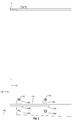
- Figure 2 illustrates the lower frame 130 of the architectural wall system 100 secured to an uneven floor 140.
- the uneven floor 140 may require both suspension of the wall 111 above the uneven surface and leveling of the wall 111 to compensate for slopes or irregularities of the floor 140. While crude adjustments can be made by masonry, carpentry, or metalworking adjustments (such as grinding the uneven floor flat), these options may be time consuming and costly and may not be feasible in certain circumstances.
- the lower frame 130 can allow crude leveling adjustments to be made.
- a permanent structure such as floor 140
- the connection of the lower frame 130 to the permanent structure can crudely level the lower frame 130 such that a support member 131 stands in a substantially vertical orientation and/or a base member 134 is oriented in a substantially horizontal orientation.
- the lower frame 130 is secured to the floor 140 by a 3-point connection comprising a set of threaded studs 132, a first set of hex nuts 133a, a second set of hex nuts 133b, and a third set of hex nuts 133c.
- the 3-point connection provides displacement, and therefore crude leveling, of the support member 131 and/or the base member 134.
- the crude leveling is accomplished by inserting the set of threaded studs 132 into holes or recesses in the floor 140 and positioning the first set of hex nuts 133a on the set of threaded studs 132.
- the relative positioning of the first set of nuts 133a on the studs 132 can determine how deep the studs 132 are inserted into the floor 140.
- the second set of nuts 133b are positioned on the studs 132. Moving one or more nuts in the second set of hex nuts 133b on the set of threaded studs 132 allows tilting of the lower frame 130.
- the base member 134 can then be secured in place upon the second set of hex nuts 133b by the third set of hex nuts 133c.
- the crude leveling could be enabled by washers, bushings, or similar spacing adjusters between the base member 134 and the permanent structure.
- the connection of the lower frame 130 to the permanent structure may be inaccessible without significant disassembly of the raised floor. Therefore, the primary, crude leveling of the lower frame 130 relative to the permanent structure in tandem with the fine leveling achieved with the intermediate displacement mechanism 120 (described in detail below) allows easier, more rapid adjustment and repairs of the wall 111 compared to prior designs.
- the architectural wall system 100 may be substantially similar, however inverted, to allow attachment to, and leveling relative to, a ceiling instead of a floor. Similarly, the architectural wall system 100 may be turned 90 degrees to facilitate attachment to a wall without substantial alteration.
- the lower frame 130 regardless of orientation of the architectural wall system 100, may be used to secure the architectural wall system 100 to the permanent structure.
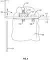
- Figures 3-4 depict cutaway views showing the intermediate displacement mechanism 120 according to one exemplary implementation.
- the intermediate displacement mechanism 120 is connected between the upper frame 110 and the lower frame 130 and can provide a spacing between the upper frame 110 and the lower frame 130 for fine adjustment of the vertical position of the wall 111 independent of the attachment to the floor 140.
- the intermediate displacement mechanism 120 comprises a pair of bolts.
- a first bolt 121 affixes the upper frame 110 to the lower frame 130 through an unthreaded hole 114 in a horizontal member 112 of the upper frame 110 and a complimentarily threaded hole 136 in a connection block 135 affixed to the support member 131 of the lower frame 130.
- a second bolt 122 passes through a threaded hole 124 in a leveling bracket 123, which is affixed to the horizontal member 112 of the upper frame 110.
- the second bolt 122 also passes through an unthreaded hole 115 in the horizontal member 112 before contacting the connection block 135 of the lower frame 130.
- the interaction between the second bolt 122, the leveling bracket 123, and the connection block 135 provides a displacement force to adjust the height of the upper frame 110 relative to the lower frame 130.
- connection block 135. a distal end of the second bolt 122 extends further out of the unthreaded hole 115 and engages the connection block 135.
- the second bolt 122 engages a top surface of the connection block 135.
- the second bolt 122 extends into a recess formed in the top surface of the connection block 135.
- a recess in the connection block 135 can facilitate and/or maintain proper alignment between the upper frame 110 and the lower frame 130 and/or between the components of the intermediate displacement mechanism 120.
- the second bolt 122 extends further through the leveling bracket 123, by tightening the bolt 122 against the connection block 135, the second bolt 122 causes at least a portion of the upper frame 110 to be raised, thereby allowing for further leveling of the wall 111.
- loosening the second bolt 122 i.e., rotating the second bolt 122 to retract the distal end further into the leveling bracket 123 causes at least a portion of the upper frame 110 to be lowered, which may also allow for further leveling of the wall 111.
- the longitudinal leveling of the wall 111 can likewise be finely adjusted with the use of the intermediate displacement mechanism 120.
- the architectural wall system 100 as described herein can ensure the upper frame 110 and/or wall 111 is level longitudinally. Additionally, the architectural wall system 100 may also allow the upper frame 110 and wall 111 to pivot up to 152, 4 mm (six inches) laterally in the event of impacts, earthquakes, building sway, or similar lateral forces that may act on the upper frame 110 and/or wall 111.
- the horizontal member 112 of the upper frame 110 has a beveled base 113 at the point where the upper frame 110 connects to the lower frame 130.
- the beveled base 113 even when the upper frame 110 and lower frame 130 are in direct contact, allows the upper frame 110 and/or wall 111 to pivot laterally without damage to any components.
- the lower frame 130 has a beveled top in alternative or addition to the beveled base 113 of the upper frame 110.
- the beveled base 113 or beveled top may alternatively be rounded.
Landscapes
- Engineering & Computer Science (AREA)
- Architecture (AREA)
- Civil Engineering (AREA)
- Structural Engineering (AREA)
- Physics & Mathematics (AREA)
- Electromagnetism (AREA)
- Finishing Walls (AREA)
- Conveying And Assembling Of Building Elements In Situ (AREA)
Claims (8)
- Architektonisches Wandsystem (100), das Folgendes umfasst:einen unteren Rahmen (130);einen oberen Rahmen (110), der mit dem unteren Rahmen (130) verbunden ist, wobei der untere Rahmen (130) mit einer permanenten Struktur verbunden werden kann;eine Wand (111), die mit dem oberen Rahmen (110) verbunden ist; undein horizontales Ausgleichselement, das so konfiguriert ist, dass es zwischen einem ersten Ende der Wand und der permanenten Struktur befestigt wird, wobei das horizontale Ausgleichselement ermöglicht, dass eine vertikale Position des ersten Endes der Wand relativ zu der permanenten Struktur wahlweise in groben Schritten und in feinen Schritten eingestellt werden kann, wobei das horizontale Ausgleichselement dadurch gekennzeichnet ist, dass es Folgendes umfasst:einen dazwischenliegenden Verlagerungsmechanismus (120), der einen Verbindungsblock (135) umfasst, der mit dem unteren Rahmen (130) verbunden ist;eine Ausgleichshalterung (123), die mit dem oberen Rahmen (110) verbunden ist;einen ersten Bolzen (121), der sich durch den oberen Rahmen (110) und in ein Gewindeloch (136) in dem Verbindungsblock (135) erstreckt, um den oberen Rahmen (110) und den unteren Rahmen (130) miteinander zu verbinden;einen zweiten Bolzen (122), der sich so durch die Ausgleichshalterung (123) erstreckt, dass ein distales Ende des zweiten Bolzens (122) mit dem Verbindungsblock (135) in Eingriff gelangen kann, wobei der zweite Bolzen durch ein Gewindeloch (124) in der Ausgleichshalterung (123) verläuft;wobei eine Feineinstellung einer vertikalen Position zwischen dem oberen Rahmen (110) und dem unteren Rahmen (130) durch den dazwischenliegenden Verlagerungsmechanismus (120) eingestellt werden kann, der so konfiguriert ist, dass er eine Verlagerungskraft zwischen dem oberen Rahmen (110) und dem unteren Rahmen (130) bereitstellt,wobei der zweite Bolzen (122) mit dem oberen Rahmen (110) verbunden ist und der zweite Bolzen (122) gegen den unteren Rahmen (130) bewegt werden kann, um eine Feineinstellung zwischen dem oberen Rahmen (110) und dem unteren Rahmen (130) bereitzustellen; unddie Grobeinstellung einer vertikalen Position zwischen dem unteren Rahmen (130) und der permanenten Struktur durch eine 3-Punkt-Verbindung zwischen dem unteren Rahmen (130) und einer permanenten Struktur eingestellt wird.
- Architektonisches Wandsystem nach Anspruch 1, wobei das horizontale Ausgleichselement ermöglicht, dass ein zweites Ende der Wand bis zu einer seitlichen Verlagerung von etwa 152,4 mm (6 Zoll) geschwenkt werden kann, wobei das zweite Ende der Wand distal zum ersten Ende der Wand ist.
- Architektonisches Wandsystem nach Anspruch 1, wobei eine Einstellung, wie weit sich der zweite Bolzen (122) aus der Ausgleichshalterung (123) erstreckt, die Höhenanpassung des oberen Rahmens (110) einstellt.
- Architektonisches Wandsystem nach Anspruch 1, wobei eine Einstellung des zweiten Bolzens (122) relativ zu der Ausgleichshalterung (123) die vertikale Position des ersten Endes der Wand einstellt.
- Architektonisches Wandsystem nach Anspruch 1, wobei die 3-Punkt-Verbindung Folgendes umfasst:einen Satz Gewindebolzen (132);einen ersten Satz Sechskantmuttern (133a);einen zweiten Satz Sechskantmuttern (133b); undeinen dritten Satz Sechskantmuttern (133c).
- Architektonisches Wandsystem nach Anspruch 5, wobei der Satz Gewindebolzen (132) in Löcher oder Vertiefungen in der permanenten Struktur eingesetzt werden kann.
- Architektonisches Wandsystem nach Anspruch 6, wobei der erste Satz Sechskantmuttern (133a) bei dem Satz Gewindebolzen (132) positioniert ist und eine Einstellung des ersten Satzes Sechskantmuttern (133a) bei dem Satz Gewindebolzen (132) die Tiefe einstellt, bis zu der der Satz Gewindebolzen (132) in Löcher oder Vertiefungen in der permanenten Struktur eingesetzt ist.
- Architektonisches Wandsystem nach Anspruch 7, wobei der zweite Satz Sechskantmuttern (133b) bei dem Satz Gewindebolzen (132) positioniert ist und eine Einstellung des zweiten Satzes Sechskantmuttern (133b) ein Kippen des unteren Rahmens (130) ermöglicht.
Applications Claiming Priority (2)
| Application Number | Priority Date | Filing Date | Title |
|---|---|---|---|
| US201361866781P | 2013-08-16 | 2013-08-16 | |
| PCT/US2014/050959 WO2015023794A1 (en) | 2013-08-16 | 2014-08-13 | Primary and intermediate horizontal leveler |
Publications (3)
| Publication Number | Publication Date |
|---|---|
| EP3033461A1 EP3033461A1 (de) | 2016-06-22 |
| EP3033461A4 EP3033461A4 (de) | 2017-07-26 |
| EP3033461B1 true EP3033461B1 (de) | 2021-03-03 |
Family
ID=52468672
Family Applications (1)
| Application Number | Title | Priority Date | Filing Date |
|---|---|---|---|
| EP14836733.7A Not-in-force EP3033461B1 (de) | 2013-08-16 | 2014-08-13 | Horizontaler primär- und zwischennivellierer |
Country Status (4)
| Country | Link |
|---|---|
| US (1) | US9617743B2 (de) |
| EP (1) | EP3033461B1 (de) |
| CA (1) | CA2888544C (de) |
| WO (1) | WO2015023794A1 (de) |
Families Citing this family (4)
| Publication number | Priority date | Publication date | Assignee | Title |
|---|---|---|---|---|
| WO2014078437A1 (en) * | 2012-11-13 | 2014-05-22 | Dirtt Environmental Solutions Inc. | Selectively adjustable architectural wall |
| US10458130B2 (en) * | 2018-02-01 | 2019-10-29 | Oldcastle Buildingenvelope, Inc. | Demountable wall system and method |
| FI128039B (en) * | 2018-05-21 | 2019-08-15 | Vetrospace Oy | Soundproof and hygienic space |
| CN111608291B (zh) * | 2020-05-22 | 2021-03-16 | 一方设计集团有限公司 | 一种模块化稳定节能建筑空腔墙体 |
Family Cites Families (37)
| Publication number | Priority date | Publication date | Assignee | Title |
|---|---|---|---|---|
| US2324545A (en) * | 1941-05-05 | 1943-07-20 | Svirsky Bennett | Pipe plug |
| US2940784A (en) * | 1956-06-06 | 1960-06-14 | William B Fell | Precision threaded adjustment |
| US3464670A (en) * | 1967-07-19 | 1969-09-02 | Kenneth L Rasmussen | Telephone booth installation tool |
| US3495365A (en) * | 1968-04-25 | 1970-02-17 | John F Blaski | Domed building construction and method |
| FR1601844A (de) * | 1968-12-30 | 1970-09-14 | ||
| US3606704A (en) * | 1969-05-02 | 1971-09-21 | Resilient Services Inc | Elevated floor structure |
| FR2271370B1 (de) * | 1974-05-17 | 1978-11-17 | Tramex Sa | |
| US4102096A (en) * | 1977-03-02 | 1978-07-25 | Symons Corporation | Leg brace assembly for adjustable shoring apparatus |
| US4320607A (en) * | 1978-10-10 | 1982-03-23 | Eubank Marcus P | Combination floor, jack and trailer assemblies |
| US4417426A (en) * | 1981-03-23 | 1983-11-29 | Quakebrace, Inc. | Support system |
| CA1242591A (en) * | 1984-12-27 | 1988-10-04 | Ronald J. Johnston | Truss arrangement |
| US5301480A (en) | 1990-11-19 | 1994-04-12 | Sumitomo Rubber Industries, Ltd. | Stanchion unit assembly for floor boards |
| US5120163A (en) * | 1990-12-07 | 1992-06-09 | A.B. Chance Company | Foundation underpinning bracket and jacking tool assembly |
| US5213448A (en) * | 1992-12-11 | 1993-05-25 | A. B. Chance Company | Underpinning bracket for uplift and settlement loading |
| US5862635A (en) | 1997-09-16 | 1999-01-26 | Magnum Foundation Systems | Support system for a building structure |
| US6193442B1 (en) * | 1999-03-16 | 2001-02-27 | Donald R. May | Method and device for raising and supporting a building foundation |
| US6142710A (en) * | 1999-07-12 | 2000-11-07 | Holland, Jr.; Thomas Edward | Apparatus and method for raising a foundation |
| JP3255628B2 (ja) * | 1999-09-24 | 2002-02-12 | 株式会社 松本工務店 | 長尺部材接合用建ち入り直し装置 |
| US6397535B1 (en) * | 2000-07-14 | 2002-06-04 | Gwang Sik Kim | Height-adjustable concrete mold supporting system and method for constructing concrete building |
| US6539685B2 (en) * | 2000-11-28 | 2003-04-01 | Thomas A. Bell | Apparatus and method for lifting sunken foundations |
| US6381907B1 (en) | 2000-12-18 | 2002-05-07 | Charles J. Mackarvich | Adjustable support system for premanufactured building |
| US6607341B1 (en) * | 2002-03-05 | 2003-08-19 | Robert A. Wade | Cabinet installation apparatus and associated methods |
| US6872031B2 (en) * | 2002-07-22 | 2005-03-29 | Donald May | Apparatus and method of supporting a structure with a pier |
| US6659692B1 (en) * | 2002-07-22 | 2003-12-09 | Donald May | Apparatus and method for supporting a structure with a pier and helix |
| US7004683B1 (en) * | 2004-03-26 | 2006-02-28 | Stan Rupiper | Helice pierhead mounting plate and bolt assembly |
| US20050284040A1 (en) * | 2004-06-03 | 2005-12-29 | Nippon Light Metal Company, Ltd. | Pedestal unit, raised floor skeleton structure, method of installing pedestal unit, and method of producing pedestal frame |
| US7195426B2 (en) * | 2005-05-24 | 2007-03-27 | Donald May | Structural pier and method for installing the same |
| US7814711B2 (en) * | 2007-05-30 | 2010-10-19 | Tk Canada Limited | Interior wall system |
| US20090211178A1 (en) * | 2008-02-27 | 2009-08-27 | Marshall Frederick S | System for Forming a Movable Slab Foundation |
| JP5475357B2 (ja) * | 2009-08-03 | 2014-04-16 | 日本軽金属株式会社 | 二重床構造および二重床用支持脚 |
| US8001733B2 (en) * | 2009-12-04 | 2011-08-23 | Min Chen | Adjustable jack post |
| US8726583B2 (en) * | 2010-04-13 | 2014-05-20 | University of South Florida (A Flordia Non-Profit Corporation) | Modular dwellings |
| AU2011250605B2 (en) * | 2010-05-05 | 2016-06-16 | Allsteel Inc. | Moveable and demountable wall panel system for butt-glazed wall panels |
| US9057201B2 (en) * | 2012-01-30 | 2015-06-16 | Teknion Limited | Interior wall system |
| US8939416B2 (en) * | 2012-08-29 | 2015-01-27 | Andre Duranleau | Front adjustable wall panel mounting device |
| SG11201605820TA (en) * | 2012-10-05 | 2016-09-29 | Dirtt Environmental Solutions | Divider wall connection systems and methods |
| US9279227B2 (en) * | 2014-01-31 | 2016-03-08 | J. Stephen West | Foundation pier system |
-
2014
- 2014-08-13 EP EP14836733.7A patent/EP3033461B1/de not_active Not-in-force
- 2014-08-13 WO PCT/US2014/050959 patent/WO2015023794A1/en not_active Ceased
- 2014-08-13 US US14/432,999 patent/US9617743B2/en active Active
- 2014-08-13 CA CA2888544A patent/CA2888544C/en active Active
Non-Patent Citations (1)
| Title |
|---|
| None * |
Also Published As
| Publication number | Publication date |
|---|---|
| EP3033461A1 (de) | 2016-06-22 |
| CA2888544A1 (en) | 2015-02-19 |
| US20160160512A1 (en) | 2016-06-09 |
| CA2888544C (en) | 2021-07-13 |
| WO2015023794A1 (en) | 2015-02-19 |
| EP3033461A4 (de) | 2017-07-26 |
| US9617743B2 (en) | 2017-04-11 |
Similar Documents
| Publication | Publication Date | Title |
|---|---|---|
| KR102285238B1 (ko) | 건축물 내외장재 및 트러스 프로파일 고정용 브라켓 | |
| WO2015145477A1 (en) | Locking and regulation device for panels and slabs | |
| CA2888544C (en) | Primary and intermediate horizontal leveler | |
| WO2020143222A1 (zh) | 一种装配式吊顶结构及其安装方法 | |
| KR20130045711A (ko) | 실내장식용 커튼월 시공장치 | |
| WO2022013831A1 (en) | Modular frame structure for a demountable wall system with a novel profile assembly | |
| CN211396423U (zh) | 一种调平结构 | |
| US6857234B2 (en) | Masonry control joint guide | |
| KR20130104725A (ko) | 연결기를 이용한 천장 에어컨 설치구조 | |
| CN113463824B (zh) | 一种用于吊顶预起拱的装置及其安装方法 | |
| KR101585833B1 (ko) | 건축물 벽체 수평 조절장치 | |
| JP2016211177A (ja) | 吊り天井補強構造 | |
| CN218758481U (zh) | 一种找平装置 | |
| EP2834440B1 (de) | Justierbare montagevorrichtung für einen rahmen und einbauverfahren | |
| EP2920378B1 (de) | Selektiv einstellbare architektonische wand | |
| PL226478B1 (pl) | Zespół do mocowania płytowych elementów elewacji | |
| KR102277613B1 (ko) | 벽돌을 이용한 천장 마감 장치 및 그 시공방법 | |
| KR200434878Y1 (ko) | 조적용 시공장치 | |
| KR200279194Y1 (ko) | 인방앵글 설치구 | |
| KR20070074533A (ko) | 수평조절 장치가 부착된 고정용 브래킷 | |
| CN208455920U (zh) | 一种房顶吊装结构 | |
| CN214614914U (zh) | 一种吊顶的支撑装置及吊顶的结构 | |
| JP6696744B2 (ja) | 吊り天井補強構造 | |
| CN217840442U (zh) | 一种墙板安装定位结构 | |
| CN220080466U (zh) | 一种轻钢龙骨吊顶 |
Legal Events
| Date | Code | Title | Description |
|---|---|---|---|
| PUAI | Public reference made under article 153(3) epc to a published international application that has entered the european phase |
Free format text: ORIGINAL CODE: 0009012 |
|
| 17P | Request for examination filed |
Effective date: 20160222 |
|
| AK | Designated contracting states |
Kind code of ref document: A1 Designated state(s): AL AT BE BG CH CY CZ DE DK EE ES FI FR GB GR HR HU IE IS IT LI LT LU LV MC MK MT NL NO PL PT RO RS SE SI SK SM TR |
|
| AX | Request for extension of the european patent |
Extension state: BA ME |
|
| DAX | Request for extension of the european patent (deleted) | ||
| REG | Reference to a national code |
Ref country code: DE Ref legal event code: R079 Ref document number: 602014075420 Country of ref document: DE Free format text: PREVIOUS MAIN CLASS: E04F0021180000 Ipc: E04B0002740000 |
|
| A4 | Supplementary search report drawn up and despatched |
Effective date: 20170628 |
|
| RIC1 | Information provided on ipc code assigned before grant |
Ipc: E04B 2/74 20060101AFI20170622BHEP |
|
| STAA | Information on the status of an ep patent application or granted ep patent |
Free format text: STATUS: EXAMINATION IS IN PROGRESS |
|
| 17Q | First examination report despatched |
Effective date: 20180207 |
|
| GRAP | Despatch of communication of intention to grant a patent |
Free format text: ORIGINAL CODE: EPIDOSNIGR1 |
|
| STAA | Information on the status of an ep patent application or granted ep patent |
Free format text: STATUS: GRANT OF PATENT IS INTENDED |
|
| INTG | Intention to grant announced |
Effective date: 20200925 |
|
| GRAS | Grant fee paid |
Free format text: ORIGINAL CODE: EPIDOSNIGR3 |
|
| GRAA | (expected) grant |
Free format text: ORIGINAL CODE: 0009210 |
|
| STAA | Information on the status of an ep patent application or granted ep patent |
Free format text: STATUS: THE PATENT HAS BEEN GRANTED |
|
| AK | Designated contracting states |
Kind code of ref document: B1 Designated state(s): AL AT BE BG CH CY CZ DE DK EE ES FI FR GB GR HR HU IE IS IT LI LT LU LV MC MK MT NL NO PL PT RO RS SE SI SK SM TR |
|
| REG | Reference to a national code |
Ref country code: GB Ref legal event code: FG4D |
|
| REG | Reference to a national code |
Ref country code: AT Ref legal event code: REF Ref document number: 1367349 Country of ref document: AT Kind code of ref document: T Effective date: 20210315 Ref country code: CH Ref legal event code: EP |
|
| REG | Reference to a national code |
Ref country code: DE Ref legal event code: R096 Ref document number: 602014075420 Country of ref document: DE |
|
| REG | Reference to a national code |
Ref country code: IE Ref legal event code: FG4D |
|
| REG | Reference to a national code |
Ref country code: LT Ref legal event code: MG9D |
|
| PG25 | Lapsed in a contracting state [announced via postgrant information from national office to epo] |
Ref country code: LT Free format text: LAPSE BECAUSE OF FAILURE TO SUBMIT A TRANSLATION OF THE DESCRIPTION OR TO PAY THE FEE WITHIN THE PRESCRIBED TIME-LIMIT Effective date: 20210303 Ref country code: FI Free format text: LAPSE BECAUSE OF FAILURE TO SUBMIT A TRANSLATION OF THE DESCRIPTION OR TO PAY THE FEE WITHIN THE PRESCRIBED TIME-LIMIT Effective date: 20210303 Ref country code: GR Free format text: LAPSE BECAUSE OF FAILURE TO SUBMIT A TRANSLATION OF THE DESCRIPTION OR TO PAY THE FEE WITHIN THE PRESCRIBED TIME-LIMIT Effective date: 20210604 Ref country code: HR Free format text: LAPSE BECAUSE OF FAILURE TO SUBMIT A TRANSLATION OF THE DESCRIPTION OR TO PAY THE FEE WITHIN THE PRESCRIBED TIME-LIMIT Effective date: 20210303 Ref country code: BG Free format text: LAPSE BECAUSE OF FAILURE TO SUBMIT A TRANSLATION OF THE DESCRIPTION OR TO PAY THE FEE WITHIN THE PRESCRIBED TIME-LIMIT Effective date: 20210603 Ref country code: NO Free format text: LAPSE BECAUSE OF FAILURE TO SUBMIT A TRANSLATION OF THE DESCRIPTION OR TO PAY THE FEE WITHIN THE PRESCRIBED TIME-LIMIT Effective date: 20210603 |
|
| REG | Reference to a national code |
Ref country code: NL Ref legal event code: MP Effective date: 20210303 |
|
| REG | Reference to a national code |
Ref country code: AT Ref legal event code: MK05 Ref document number: 1367349 Country of ref document: AT Kind code of ref document: T Effective date: 20210303 |
|
| PG25 | Lapsed in a contracting state [announced via postgrant information from national office to epo] |
Ref country code: RS Free format text: LAPSE BECAUSE OF FAILURE TO SUBMIT A TRANSLATION OF THE DESCRIPTION OR TO PAY THE FEE WITHIN THE PRESCRIBED TIME-LIMIT Effective date: 20210303 Ref country code: LV Free format text: LAPSE BECAUSE OF FAILURE TO SUBMIT A TRANSLATION OF THE DESCRIPTION OR TO PAY THE FEE WITHIN THE PRESCRIBED TIME-LIMIT Effective date: 20210303 Ref country code: PL Free format text: LAPSE BECAUSE OF FAILURE TO SUBMIT A TRANSLATION OF THE DESCRIPTION OR TO PAY THE FEE WITHIN THE PRESCRIBED TIME-LIMIT Effective date: 20210303 Ref country code: SE Free format text: LAPSE BECAUSE OF FAILURE TO SUBMIT A TRANSLATION OF THE DESCRIPTION OR TO PAY THE FEE WITHIN THE PRESCRIBED TIME-LIMIT Effective date: 20210303 |
|
| PG25 | Lapsed in a contracting state [announced via postgrant information from national office to epo] |
Ref country code: NL Free format text: LAPSE BECAUSE OF FAILURE TO SUBMIT A TRANSLATION OF THE DESCRIPTION OR TO PAY THE FEE WITHIN THE PRESCRIBED TIME-LIMIT Effective date: 20210303 |
|
| PG25 | Lapsed in a contracting state [announced via postgrant information from national office to epo] |
Ref country code: EE Free format text: LAPSE BECAUSE OF FAILURE TO SUBMIT A TRANSLATION OF THE DESCRIPTION OR TO PAY THE FEE WITHIN THE PRESCRIBED TIME-LIMIT Effective date: 20210303 Ref country code: CZ Free format text: LAPSE BECAUSE OF FAILURE TO SUBMIT A TRANSLATION OF THE DESCRIPTION OR TO PAY THE FEE WITHIN THE PRESCRIBED TIME-LIMIT Effective date: 20210303 Ref country code: AT Free format text: LAPSE BECAUSE OF FAILURE TO SUBMIT A TRANSLATION OF THE DESCRIPTION OR TO PAY THE FEE WITHIN THE PRESCRIBED TIME-LIMIT Effective date: 20210303 Ref country code: SM Free format text: LAPSE BECAUSE OF FAILURE TO SUBMIT A TRANSLATION OF THE DESCRIPTION OR TO PAY THE FEE WITHIN THE PRESCRIBED TIME-LIMIT Effective date: 20210303 |
|
| PG25 | Lapsed in a contracting state [announced via postgrant information from national office to epo] |
Ref country code: IS Free format text: LAPSE BECAUSE OF FAILURE TO SUBMIT A TRANSLATION OF THE DESCRIPTION OR TO PAY THE FEE WITHIN THE PRESCRIBED TIME-LIMIT Effective date: 20210703 Ref country code: ES Free format text: LAPSE BECAUSE OF FAILURE TO SUBMIT A TRANSLATION OF THE DESCRIPTION OR TO PAY THE FEE WITHIN THE PRESCRIBED TIME-LIMIT Effective date: 20210303 Ref country code: PT Free format text: LAPSE BECAUSE OF FAILURE TO SUBMIT A TRANSLATION OF THE DESCRIPTION OR TO PAY THE FEE WITHIN THE PRESCRIBED TIME-LIMIT Effective date: 20210705 Ref country code: SK Free format text: LAPSE BECAUSE OF FAILURE TO SUBMIT A TRANSLATION OF THE DESCRIPTION OR TO PAY THE FEE WITHIN THE PRESCRIBED TIME-LIMIT Effective date: 20210303 Ref country code: RO Free format text: LAPSE BECAUSE OF FAILURE TO SUBMIT A TRANSLATION OF THE DESCRIPTION OR TO PAY THE FEE WITHIN THE PRESCRIBED TIME-LIMIT Effective date: 20210303 |
|
| REG | Reference to a national code |
Ref country code: DE Ref legal event code: R097 Ref document number: 602014075420 Country of ref document: DE |
|
| PLBE | No opposition filed within time limit |
Free format text: ORIGINAL CODE: 0009261 |
|
| STAA | Information on the status of an ep patent application or granted ep patent |
Free format text: STATUS: NO OPPOSITION FILED WITHIN TIME LIMIT |
|
| PG25 | Lapsed in a contracting state [announced via postgrant information from national office to epo] |
Ref country code: DK Free format text: LAPSE BECAUSE OF FAILURE TO SUBMIT A TRANSLATION OF THE DESCRIPTION OR TO PAY THE FEE WITHIN THE PRESCRIBED TIME-LIMIT Effective date: 20210303 Ref country code: AL Free format text: LAPSE BECAUSE OF FAILURE TO SUBMIT A TRANSLATION OF THE DESCRIPTION OR TO PAY THE FEE WITHIN THE PRESCRIBED TIME-LIMIT Effective date: 20210303 |
|
| 26N | No opposition filed |
Effective date: 20211206 |
|
| PG25 | Lapsed in a contracting state [announced via postgrant information from national office to epo] |
Ref country code: SI Free format text: LAPSE BECAUSE OF FAILURE TO SUBMIT A TRANSLATION OF THE DESCRIPTION OR TO PAY THE FEE WITHIN THE PRESCRIBED TIME-LIMIT Effective date: 20210303 |
|
| REG | Reference to a national code |
Ref country code: DE Ref legal event code: R119 Ref document number: 602014075420 Country of ref document: DE |
|
| REG | Reference to a national code |
Ref country code: CH Ref legal event code: PL |
|
| PG25 | Lapsed in a contracting state [announced via postgrant information from national office to epo] |
Ref country code: MC Free format text: LAPSE BECAUSE OF FAILURE TO SUBMIT A TRANSLATION OF THE DESCRIPTION OR TO PAY THE FEE WITHIN THE PRESCRIBED TIME-LIMIT Effective date: 20210303 |
|
| REG | Reference to a national code |
Ref country code: BE Ref legal event code: MM Effective date: 20210831 |
|
| PG25 | Lapsed in a contracting state [announced via postgrant information from national office to epo] |
Ref country code: LI Free format text: LAPSE BECAUSE OF NON-PAYMENT OF DUE FEES Effective date: 20210831 Ref country code: IT Free format text: LAPSE BECAUSE OF FAILURE TO SUBMIT A TRANSLATION OF THE DESCRIPTION OR TO PAY THE FEE WITHIN THE PRESCRIBED TIME-LIMIT Effective date: 20210303 Ref country code: CH Free format text: LAPSE BECAUSE OF NON-PAYMENT OF DUE FEES Effective date: 20210831 |
|
| PG25 | Lapsed in a contracting state [announced via postgrant information from national office to epo] |
Ref country code: IS Free format text: LAPSE BECAUSE OF FAILURE TO SUBMIT A TRANSLATION OF THE DESCRIPTION OR TO PAY THE FEE WITHIN THE PRESCRIBED TIME-LIMIT Effective date: 20210703 Ref country code: LU Free format text: LAPSE BECAUSE OF NON-PAYMENT OF DUE FEES Effective date: 20210813 |
|
| PG25 | Lapsed in a contracting state [announced via postgrant information from national office to epo] |
Ref country code: IE Free format text: LAPSE BECAUSE OF NON-PAYMENT OF DUE FEES Effective date: 20210813 Ref country code: FR Free format text: LAPSE BECAUSE OF NON-PAYMENT OF DUE FEES Effective date: 20210831 Ref country code: DE Free format text: LAPSE BECAUSE OF NON-PAYMENT OF DUE FEES Effective date: 20220301 Ref country code: BE Free format text: LAPSE BECAUSE OF NON-PAYMENT OF DUE FEES Effective date: 20210831 |
|
| PGFP | Annual fee paid to national office [announced via postgrant information from national office to epo] |
Ref country code: GB Payment date: 20220829 Year of fee payment: 9 |
|
| PG25 | Lapsed in a contracting state [announced via postgrant information from national office to epo] |
Ref country code: HU Free format text: LAPSE BECAUSE OF FAILURE TO SUBMIT A TRANSLATION OF THE DESCRIPTION OR TO PAY THE FEE WITHIN THE PRESCRIBED TIME-LIMIT; INVALID AB INITIO Effective date: 20140813 |
|
| PG25 | Lapsed in a contracting state [announced via postgrant information from national office to epo] |
Ref country code: CY Free format text: LAPSE BECAUSE OF FAILURE TO SUBMIT A TRANSLATION OF THE DESCRIPTION OR TO PAY THE FEE WITHIN THE PRESCRIBED TIME-LIMIT Effective date: 20210303 |
|
| GBPC | Gb: european patent ceased through non-payment of renewal fee |
Effective date: 20230813 |
|
| PG25 | Lapsed in a contracting state [announced via postgrant information from national office to epo] |
Ref country code: MK Free format text: LAPSE BECAUSE OF FAILURE TO SUBMIT A TRANSLATION OF THE DESCRIPTION OR TO PAY THE FEE WITHIN THE PRESCRIBED TIME-LIMIT Effective date: 20210303 |
|
| PG25 | Lapsed in a contracting state [announced via postgrant information from national office to epo] |
Ref country code: GB Free format text: LAPSE BECAUSE OF NON-PAYMENT OF DUE FEES Effective date: 20230813 |
|
| PG25 | Lapsed in a contracting state [announced via postgrant information from national office to epo] |
Ref country code: GB Free format text: LAPSE BECAUSE OF NON-PAYMENT OF DUE FEES Effective date: 20230813 |
|
| PG25 | Lapsed in a contracting state [announced via postgrant information from national office to epo] |
Ref country code: MT Free format text: LAPSE BECAUSE OF FAILURE TO SUBMIT A TRANSLATION OF THE DESCRIPTION OR TO PAY THE FEE WITHIN THE PRESCRIBED TIME-LIMIT Effective date: 20210303 |
|
| PG25 | Lapsed in a contracting state [announced via postgrant information from national office to epo] |
Ref country code: TR Free format text: LAPSE BECAUSE OF FAILURE TO SUBMIT A TRANSLATION OF THE DESCRIPTION OR TO PAY THE FEE WITHIN THE PRESCRIBED TIME-LIMIT Effective date: 20210303 |