EP3033232B1 - Creation of a transparent polymer window with a field of lenses in a security paper substrate - Google Patents
Creation of a transparent polymer window with a field of lenses in a security paper substrate Download PDFInfo
- Publication number
- EP3033232B1 EP3033232B1 EP14780598.0A EP14780598A EP3033232B1 EP 3033232 B1 EP3033232 B1 EP 3033232B1 EP 14780598 A EP14780598 A EP 14780598A EP 3033232 B1 EP3033232 B1 EP 3033232B1
- Authority
- EP
- European Patent Office
- Prior art keywords
- paper substrate
- security paper
- polymer material
- opening
- transparent polymer
- Prior art date
- Legal status (The legal status is an assumption and is not a legal conclusion. Google has not performed a legal analysis and makes no representation as to the accuracy of the status listed.)
- Not-in-force
Links
Images


Classifications
-
- B—PERFORMING OPERATIONS; TRANSPORTING
- B32—LAYERED PRODUCTS
- B32B—LAYERED PRODUCTS, i.e. PRODUCTS BUILT-UP OF STRATA OF FLAT OR NON-FLAT, e.g. CELLULAR OR HONEYCOMB, FORM
- B32B38/00—Ancillary operations in connection with laminating processes
- B32B38/04—Punching, slitting or perforating
-
- B—PERFORMING OPERATIONS; TRANSPORTING
- B29—WORKING OF PLASTICS; WORKING OF SUBSTANCES IN A PLASTIC STATE IN GENERAL
- B29C—SHAPING OR JOINING OF PLASTICS; SHAPING OF MATERIAL IN A PLASTIC STATE, NOT OTHERWISE PROVIDED FOR; AFTER-TREATMENT OF THE SHAPED PRODUCTS, e.g. REPAIRING
- B29C39/00—Shaping by casting, i.e. introducing the moulding material into a mould or between confining surfaces without significant moulding pressure; Apparatus therefor
- B29C39/003—Shaping by casting, i.e. introducing the moulding material into a mould or between confining surfaces without significant moulding pressure; Apparatus therefor characterised by the choice of material
-
- B—PERFORMING OPERATIONS; TRANSPORTING
- B29—WORKING OF PLASTICS; WORKING OF SUBSTANCES IN A PLASTIC STATE IN GENERAL
- B29C—SHAPING OR JOINING OF PLASTICS; SHAPING OF MATERIAL IN A PLASTIC STATE, NOT OTHERWISE PROVIDED FOR; AFTER-TREATMENT OF THE SHAPED PRODUCTS, e.g. REPAIRING
- B29C39/00—Shaping by casting, i.e. introducing the moulding material into a mould or between confining surfaces without significant moulding pressure; Apparatus therefor
- B29C39/02—Shaping by casting, i.e. introducing the moulding material into a mould or between confining surfaces without significant moulding pressure; Apparatus therefor for making articles of definite length, i.e. discrete articles
- B29C39/10—Shaping by casting, i.e. introducing the moulding material into a mould or between confining surfaces without significant moulding pressure; Apparatus therefor for making articles of definite length, i.e. discrete articles incorporating preformed parts or layers, e.g. casting around inserts or for coating articles
-
- B—PERFORMING OPERATIONS; TRANSPORTING
- B29—WORKING OF PLASTICS; WORKING OF SUBSTANCES IN A PLASTIC STATE IN GENERAL
- B29C—SHAPING OR JOINING OF PLASTICS; SHAPING OF MATERIAL IN A PLASTIC STATE, NOT OTHERWISE PROVIDED FOR; AFTER-TREATMENT OF THE SHAPED PRODUCTS, e.g. REPAIRING
- B29C69/00—Combinations of shaping techniques not provided for in a single one of main groups B29C39/00 - B29C67/00, e.g. associations of moulding and joining techniques; Apparatus therefore
- B29C69/001—Combinations of shaping techniques not provided for in a single one of main groups B29C39/00 - B29C67/00, e.g. associations of moulding and joining techniques; Apparatus therefore a shaping technique combined with cutting, e.g. in parts or slices combined with rearranging and joining the cut parts
-
- B—PERFORMING OPERATIONS; TRANSPORTING
- B29—WORKING OF PLASTICS; WORKING OF SUBSTANCES IN A PLASTIC STATE IN GENERAL
- B29D—PRODUCING PARTICULAR ARTICLES FROM PLASTICS OR FROM SUBSTANCES IN A PLASTIC STATE
- B29D11/00—Producing optical elements, e.g. lenses or prisms
- B29D11/00009—Production of simple or compound lenses
- B29D11/00432—Auxiliary operations, e.g. machines for filling the moulds
- B29D11/00442—Curing the lens material
-
- B—PERFORMING OPERATIONS; TRANSPORTING
- B32—LAYERED PRODUCTS
- B32B—LAYERED PRODUCTS, i.e. PRODUCTS BUILT-UP OF STRATA OF FLAT OR NON-FLAT, e.g. CELLULAR OR HONEYCOMB, FORM
- B32B3/00—Layered products comprising a layer with external or internal discontinuities or unevennesses, or a layer of non-planar form; Layered products having particular features of form
- B32B3/10—Layered products comprising a layer with external or internal discontinuities or unevennesses, or a layer of non-planar form; Layered products having particular features of form characterised by a discontinuous layer, i.e. formed of separate pieces of material
- B32B3/14—Layered products comprising a layer with external or internal discontinuities or unevennesses, or a layer of non-planar form; Layered products having particular features of form characterised by a discontinuous layer, i.e. formed of separate pieces of material characterised by a face layer formed of separate pieces of material which are juxtaposed side-by-side
-
- B—PERFORMING OPERATIONS; TRANSPORTING
- B32—LAYERED PRODUCTS
- B32B—LAYERED PRODUCTS, i.e. PRODUCTS BUILT-UP OF STRATA OF FLAT OR NON-FLAT, e.g. CELLULAR OR HONEYCOMB, FORM
- B32B37/00—Methods or apparatus for laminating, e.g. by curing or by ultrasonic bonding
- B32B37/14—Methods or apparatus for laminating, e.g. by curing or by ultrasonic bonding characterised by the properties of the layers
- B32B37/16—Methods or apparatus for laminating, e.g. by curing or by ultrasonic bonding characterised by the properties of the layers with all layers existing as coherent layers before laminating
- B32B37/18—Methods or apparatus for laminating, e.g. by curing or by ultrasonic bonding characterised by the properties of the layers with all layers existing as coherent layers before laminating involving the assembly of discrete sheets or panels only
-
- B—PERFORMING OPERATIONS; TRANSPORTING
- B32—LAYERED PRODUCTS
- B32B—LAYERED PRODUCTS, i.e. PRODUCTS BUILT-UP OF STRATA OF FLAT OR NON-FLAT, e.g. CELLULAR OR HONEYCOMB, FORM
- B32B38/00—Ancillary operations in connection with laminating processes
- B32B38/0004—Cutting, tearing or severing, e.g. bursting; Cutter details
-
- B—PERFORMING OPERATIONS; TRANSPORTING
- B32—LAYERED PRODUCTS
- B32B—LAYERED PRODUCTS, i.e. PRODUCTS BUILT-UP OF STRATA OF FLAT OR NON-FLAT, e.g. CELLULAR OR HONEYCOMB, FORM
- B32B38/00—Ancillary operations in connection with laminating processes
- B32B38/06—Embossing
-
- B—PERFORMING OPERATIONS; TRANSPORTING
- B32—LAYERED PRODUCTS
- B32B—LAYERED PRODUCTS, i.e. PRODUCTS BUILT-UP OF STRATA OF FLAT OR NON-FLAT, e.g. CELLULAR OR HONEYCOMB, FORM
- B32B9/00—Layered products comprising a layer of a particular substance not covered by groups B32B11/00 - B32B29/00
- B32B9/04—Layered products comprising a layer of a particular substance not covered by groups B32B11/00 - B32B29/00 comprising such particular substance as the main or only constituent of a layer, which is next to another layer of the same or of a different material
- B32B9/06—Layered products comprising a layer of a particular substance not covered by groups B32B11/00 - B32B29/00 comprising such particular substance as the main or only constituent of a layer, which is next to another layer of the same or of a different material of paper or cardboard
-
- B—PERFORMING OPERATIONS; TRANSPORTING
- B41—PRINTING; LINING MACHINES; TYPEWRITERS; STAMPS
- B41F—PRINTING MACHINES OR PRESSES
- B41F15/00—Screen printers
- B41F15/08—Machines
- B41F15/0831—Machines for printing webs
- B41F15/0836—Machines for printing webs by means of cylindrical screens or screens in the form of endless belts
-
- B—PERFORMING OPERATIONS; TRANSPORTING
- B42—BOOKBINDING; ALBUMS; FILES; SPECIAL PRINTED MATTER
- B42D—BOOKS; BOOK COVERS; LOOSE LEAVES; PRINTED MATTER CHARACTERISED BY IDENTIFICATION OR SECURITY FEATURES; PRINTED MATTER OF SPECIAL FORMAT OR STYLE NOT OTHERWISE PROVIDED FOR; DEVICES FOR USE THEREWITH AND NOT OTHERWISE PROVIDED FOR; MOVABLE-STRIP WRITING OR READING APPARATUS
- B42D25/00—Information-bearing cards or sheet-like structures characterised by identification or security features; Manufacture thereof
- B42D25/20—Information-bearing cards or sheet-like structures characterised by identification or security features; Manufacture thereof characterised by a particular use or purpose
- B42D25/29—Securities; Bank notes
-
- B—PERFORMING OPERATIONS; TRANSPORTING
- B42—BOOKBINDING; ALBUMS; FILES; SPECIAL PRINTED MATTER
- B42D—BOOKS; BOOK COVERS; LOOSE LEAVES; PRINTED MATTER CHARACTERISED BY IDENTIFICATION OR SECURITY FEATURES; PRINTED MATTER OF SPECIAL FORMAT OR STYLE NOT OTHERWISE PROVIDED FOR; DEVICES FOR USE THEREWITH AND NOT OTHERWISE PROVIDED FOR; MOVABLE-STRIP WRITING OR READING APPARATUS
- B42D25/00—Information-bearing cards or sheet-like structures characterised by identification or security features; Manufacture thereof
- B42D25/30—Identification or security features, e.g. for preventing forgery
- B42D25/324—Reliefs
-
- B—PERFORMING OPERATIONS; TRANSPORTING
- B42—BOOKBINDING; ALBUMS; FILES; SPECIAL PRINTED MATTER
- B42D—BOOKS; BOOK COVERS; LOOSE LEAVES; PRINTED MATTER CHARACTERISED BY IDENTIFICATION OR SECURITY FEATURES; PRINTED MATTER OF SPECIAL FORMAT OR STYLE NOT OTHERWISE PROVIDED FOR; DEVICES FOR USE THEREWITH AND NOT OTHERWISE PROVIDED FOR; MOVABLE-STRIP WRITING OR READING APPARATUS
- B42D25/00—Information-bearing cards or sheet-like structures characterised by identification or security features; Manufacture thereof
- B42D25/30—Identification or security features, e.g. for preventing forgery
- B42D25/351—Translucent or partly translucent parts, e.g. windows
-
- B—PERFORMING OPERATIONS; TRANSPORTING
- B42—BOOKBINDING; ALBUMS; FILES; SPECIAL PRINTED MATTER
- B42D—BOOKS; BOOK COVERS; LOOSE LEAVES; PRINTED MATTER CHARACTERISED BY IDENTIFICATION OR SECURITY FEATURES; PRINTED MATTER OF SPECIAL FORMAT OR STYLE NOT OTHERWISE PROVIDED FOR; DEVICES FOR USE THEREWITH AND NOT OTHERWISE PROVIDED FOR; MOVABLE-STRIP WRITING OR READING APPARATUS
- B42D25/00—Information-bearing cards or sheet-like structures characterised by identification or security features; Manufacture thereof
- B42D25/40—Manufacture
- B42D25/405—Marking
- B42D25/425—Marking by deformation, e.g. embossing
-
- B—PERFORMING OPERATIONS; TRANSPORTING
- B42—BOOKBINDING; ALBUMS; FILES; SPECIAL PRINTED MATTER
- B42D—BOOKS; BOOK COVERS; LOOSE LEAVES; PRINTED MATTER CHARACTERISED BY IDENTIFICATION OR SECURITY FEATURES; PRINTED MATTER OF SPECIAL FORMAT OR STYLE NOT OTHERWISE PROVIDED FOR; DEVICES FOR USE THEREWITH AND NOT OTHERWISE PROVIDED FOR; MOVABLE-STRIP WRITING OR READING APPARATUS
- B42D25/00—Information-bearing cards or sheet-like structures characterised by identification or security features; Manufacture thereof
- B42D25/40—Manufacture
- B42D25/405—Marking
- B42D25/43—Marking by removal of material
- B42D25/435—Marking by removal of material using electromagnetic radiation, e.g. laser
-
- B—PERFORMING OPERATIONS; TRANSPORTING
- B42—BOOKBINDING; ALBUMS; FILES; SPECIAL PRINTED MATTER
- B42D—BOOKS; BOOK COVERS; LOOSE LEAVES; PRINTED MATTER CHARACTERISED BY IDENTIFICATION OR SECURITY FEATURES; PRINTED MATTER OF SPECIAL FORMAT OR STYLE NOT OTHERWISE PROVIDED FOR; DEVICES FOR USE THEREWITH AND NOT OTHERWISE PROVIDED FOR; MOVABLE-STRIP WRITING OR READING APPARATUS
- B42D25/00—Information-bearing cards or sheet-like structures characterised by identification or security features; Manufacture thereof
- B42D25/40—Manufacture
- B42D25/405—Marking
- B42D25/43—Marking by removal of material
- B42D25/44—Marking by removal of material using mechanical means, e.g. engraving
-
- B—PERFORMING OPERATIONS; TRANSPORTING
- B42—BOOKBINDING; ALBUMS; FILES; SPECIAL PRINTED MATTER
- B42D—BOOKS; BOOK COVERS; LOOSE LEAVES; PRINTED MATTER CHARACTERISED BY IDENTIFICATION OR SECURITY FEATURES; PRINTED MATTER OF SPECIAL FORMAT OR STYLE NOT OTHERWISE PROVIDED FOR; DEVICES FOR USE THEREWITH AND NOT OTHERWISE PROVIDED FOR; MOVABLE-STRIP WRITING OR READING APPARATUS
- B42D25/00—Information-bearing cards or sheet-like structures characterised by identification or security features; Manufacture thereof
- B42D25/40—Manufacture
- B42D25/45—Associating two or more layers
- B42D25/46—Associating two or more layers using pressure
-
- B—PERFORMING OPERATIONS; TRANSPORTING
- B42—BOOKBINDING; ALBUMS; FILES; SPECIAL PRINTED MATTER
- B42D—BOOKS; BOOK COVERS; LOOSE LEAVES; PRINTED MATTER CHARACTERISED BY IDENTIFICATION OR SECURITY FEATURES; PRINTED MATTER OF SPECIAL FORMAT OR STYLE NOT OTHERWISE PROVIDED FOR; DEVICES FOR USE THEREWITH AND NOT OTHERWISE PROVIDED FOR; MOVABLE-STRIP WRITING OR READING APPARATUS
- B42D25/00—Information-bearing cards or sheet-like structures characterised by identification or security features; Manufacture thereof
- B42D25/40—Manufacture
- B42D25/475—Cutting cards
-
- D—TEXTILES; PAPER
- D21—PAPER-MAKING; PRODUCTION OF CELLULOSE
- D21H—PULP COMPOSITIONS; PREPARATION THEREOF NOT COVERED BY SUBCLASSES D21C OR D21D; IMPREGNATING OR COATING OF PAPER; TREATMENT OF FINISHED PAPER NOT COVERED BY CLASS B31 OR SUBCLASS D21G; PAPER NOT OTHERWISE PROVIDED FOR
- D21H21/00—Non-fibrous material added to the pulp, characterised by its function, form or properties; Paper-impregnating or coating material, characterised by its function, form or properties
- D21H21/14—Non-fibrous material added to the pulp, characterised by its function, form or properties; Paper-impregnating or coating material, characterised by its function, form or properties characterised by function or properties in or on the paper
- D21H21/40—Agents facilitating proof of genuineness or preventing fraudulent alteration, e.g. for security paper
-
- D—TEXTILES; PAPER
- D21—PAPER-MAKING; PRODUCTION OF CELLULOSE
- D21H—PULP COMPOSITIONS; PREPARATION THEREOF NOT COVERED BY SUBCLASSES D21C OR D21D; IMPREGNATING OR COATING OF PAPER; TREATMENT OF FINISHED PAPER NOT COVERED BY CLASS B31 OR SUBCLASS D21G; PAPER NOT OTHERWISE PROVIDED FOR
- D21H25/00—After-treatment of paper not provided for in groups D21H17/00 - D21H23/00
- D21H25/04—Physical treatment, e.g. heating, irradiating
- D21H25/06—Physical treatment, e.g. heating, irradiating of impregnated or coated paper
-
- B—PERFORMING OPERATIONS; TRANSPORTING
- B29—WORKING OF PLASTICS; WORKING OF SUBSTANCES IN A PLASTIC STATE IN GENERAL
- B29K—INDEXING SCHEME ASSOCIATED WITH SUBCLASSES B29B, B29C OR B29D, RELATING TO MOULDING MATERIALS OR TO MATERIALS FOR MOULDS, REINFORCEMENTS, FILLERS OR PREFORMED PARTS, e.g. INSERTS
- B29K2711/00—Use of natural products or their composites, not provided for in groups B29K2601/00 - B29K2709/00, for preformed parts, e.g. for inserts
- B29K2711/12—Paper, e.g. cardboard
-
- B—PERFORMING OPERATIONS; TRANSPORTING
- B29—WORKING OF PLASTICS; WORKING OF SUBSTANCES IN A PLASTIC STATE IN GENERAL
- B29K—INDEXING SCHEME ASSOCIATED WITH SUBCLASSES B29B, B29C OR B29D, RELATING TO MOULDING MATERIALS OR TO MATERIALS FOR MOULDS, REINFORCEMENTS, FILLERS OR PREFORMED PARTS, e.g. INSERTS
- B29K2995/00—Properties of moulding materials, reinforcements, fillers, preformed parts or moulds
- B29K2995/0018—Properties of moulding materials, reinforcements, fillers, preformed parts or moulds having particular optical properties, e.g. fluorescent or phosphorescent
- B29K2995/0026—Transparent
-
- B—PERFORMING OPERATIONS; TRANSPORTING
- B29—WORKING OF PLASTICS; WORKING OF SUBSTANCES IN A PLASTIC STATE IN GENERAL
- B29L—INDEXING SCHEME ASSOCIATED WITH SUBCLASS B29C, RELATING TO PARTICULAR ARTICLES
- B29L2017/00—Carriers for sound or information
-
- B—PERFORMING OPERATIONS; TRANSPORTING
- B32—LAYERED PRODUCTS
- B32B—LAYERED PRODUCTS, i.e. PRODUCTS BUILT-UP OF STRATA OF FLAT OR NON-FLAT, e.g. CELLULAR OR HONEYCOMB, FORM
- B32B38/00—Ancillary operations in connection with laminating processes
- B32B38/04—Punching, slitting or perforating
- B32B2038/042—Punching
-
- B—PERFORMING OPERATIONS; TRANSPORTING
- B32—LAYERED PRODUCTS
- B32B—LAYERED PRODUCTS, i.e. PRODUCTS BUILT-UP OF STRATA OF FLAT OR NON-FLAT, e.g. CELLULAR OR HONEYCOMB, FORM
- B32B2250/00—Layers arrangement
- B32B2250/02—2 layers
-
- B—PERFORMING OPERATIONS; TRANSPORTING
- B32—LAYERED PRODUCTS
- B32B—LAYERED PRODUCTS, i.e. PRODUCTS BUILT-UP OF STRATA OF FLAT OR NON-FLAT, e.g. CELLULAR OR HONEYCOMB, FORM
- B32B2305/00—Condition, form or state of the layers or laminate
- B32B2305/34—Inserts
- B32B2305/347—Security elements
-
- B—PERFORMING OPERATIONS; TRANSPORTING
- B32—LAYERED PRODUCTS
- B32B—LAYERED PRODUCTS, i.e. PRODUCTS BUILT-UP OF STRATA OF FLAT OR NON-FLAT, e.g. CELLULAR OR HONEYCOMB, FORM
- B32B2307/00—Properties of the layers or laminate
- B32B2307/40—Properties of the layers or laminate having particular optical properties
- B32B2307/412—Transparent
-
- B—PERFORMING OPERATIONS; TRANSPORTING
- B32—LAYERED PRODUCTS
- B32B—LAYERED PRODUCTS, i.e. PRODUCTS BUILT-UP OF STRATA OF FLAT OR NON-FLAT, e.g. CELLULAR OR HONEYCOMB, FORM
- B32B2317/00—Animal or vegetable based
- B32B2317/12—Paper, e.g. cardboard
-
- B—PERFORMING OPERATIONS; TRANSPORTING
- B32—LAYERED PRODUCTS
- B32B—LAYERED PRODUCTS, i.e. PRODUCTS BUILT-UP OF STRATA OF FLAT OR NON-FLAT, e.g. CELLULAR OR HONEYCOMB, FORM
- B32B2554/00—Paper of special types, e.g. banknotes
-
- B—PERFORMING OPERATIONS; TRANSPORTING
- B41—PRINTING; LINING MACHINES; TYPEWRITERS; STAMPS
- B41M—PRINTING, DUPLICATING, MARKING, OR COPYING PROCESSES; COLOUR PRINTING
- B41M3/00—Printing processes to produce particular kinds of printed work, e.g. patterns
- B41M3/14—Security printing
Definitions
- the present invention generally relates to the creation of a transparent polymer window with a field of lenses in a security paper substrate.
- DE 10 2011 108 477 A1 discloses a security element for securing value objects with a substrate with a window containing at least one hollow chamber passing through the substrate, wherein the at least one hollow chamber is filled with a filling material with a security feature, the at least one hollow chamber is covered on both sides of the substrate respectively with one at least partially light-transmissive cover foil, and that the at least one hollow chamber has a hollow chamber depth defined by the substrate thickness at the edge of the hollow chamber, lying between 0.5 ⁇ m and 140 ⁇ m, wherein the substrate is a paper substrate.
- DE 10 2009 048 145 A1 discloses a data carrier, especially a value or security document, having a window that extends from a bottom to a top of the data carrier, a foil element having a security element that covers the window on the top of the data carrier, one portion of the security element lying over the window and one portion of the security element next to the window, wherein the portion of the security element that lies over the window exhibits a radiation modification region, wherein the radiation modification region is in register with the window and wherein in the radiation modification region the visual appearance of the security element is modified by the action of electromagnetic radiation.
- DE 10 2004 026 050 A1 relates to security paper comprising a transparently filled area for the production of valuable documents such as bank notes, cheques, cheque cards, passports or shares.
- Said paper comprises at least one first layer consisting of an essentially non-transparent material, at least one first opening that penetrates the first layer of essentially non-transparent material, a filling in the first opening that is at least transparent in some areas and agents for fixing the filling in situ.
- DE 10 2004 026 050 A1 also relates to a method for producing said security paper, to the use of the latter for forgery-proofing goods of any type and to a valuable document comprising that security paper.
- US 2006/236877 A1 discloses an apparatus for producing a microreplicated article.
- This apparatus includes a first patterned roll having a first diameter and a second patterned roll having a second diameter.
- a drive assembly is included and is configured to rotate the first patterned roll and the second patterned roll such that the first and second rolls maintain a continuous registration within about 100 micrometers.
- the second diameter is 0.01 to 1 percent larger than the first diameter.
- a method of making a microreplicated article is also disclosed.
- a general aim of the invention is therefore to improve the solutions of the prior art.
- an aim of the present invention is to provide such a solution that can suitably allow for the creation of a transparent polymer window with a field of lenses in a security paper substrate.
- a processing machine comprising (i) a laminating system designed to laminate a transparent film onto a first side of the security paper substrate in such a way as to close one end of an opening formed into a security paper substrate and (ii) a device in accordance with the invention designed to fill the opening with transparent polymer material.
- the present invention will be described in the particular context of the creation of transparent polymer windows into security paper substrates which are provided in the form of successive sheets, the security paper substrates being provided with an opening which is closed at one end by a transparent film that is laminated onto a first side of the security paper substrate.
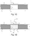
- the security paper substrate 1 is first provided with an opening 10, namely a through-hole. This can be performed by punching or cutting (for instance by means of a suitable mechanical cutting tool or by means of a laser beam) a hole through the thickness of the security paper substrate 1.
- This opening 10 can exhibit any desired shape and/or dimensions.
- the opening 10 is then closed at one end by a transparent film 5 that is laminated onto a first side I of the security paper substrate 1 as illustrated by Figure 1C , which lamination can be performed according to the principle taught by International ( PCT) Publications Nos. WO 2008/104904 A1 , WO 2009/112989 A1 and WO 2010/001317 A1 .
- the transparent film 5 is already provided with a field of lenses L and the transparent film 5 is laminated in such a way as to close the opening 10 and form the lenses L on the first side I of the security paper substrate 1 in register with the opening 10.
- the lenses L can exhibit any desired shape and may for instance consist of a parallel arrangement of semi-cylindrical lenses or a two-dimensional array of individual lens elements, such as hemispherical or hexagonal lenses.
- This transparent polymer material 2 is a UV-curable polymer material which is cured by UV radiation, in this first embodiment, from a second side II of the security paper substrate 1, opposite to the first side I.
- the security paper substrate 1 thus provided with the transparent polymer window W can suitably be printed on the second side II with patterns, in register with the lenses L, so as to interact with the lenses L and form an optically-variable security feature that is observable through the window W and lenses L, from the first side Iof the security paper substrate 1.
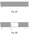
- FIGs 2A-E illustrate a second embodiment of the invention wherein the security paper substrate 1 is first provided, like in the first embodiment, with an opening 10 ( Figure 2B ) which is then closed at one end by a transparent film 5* that is laminated onto a first side I of the security paper substrate 1 ( Figure 2C ).
- the transparent film 5* is not provided with any lenses L.
- the opening 10 is likewise filled with transparent polymer material 2.
- the transparent polymer material 2 is subjected to a further processing step as illustrated by Figure 2D which consists in the replication of a field of lenses L into the transparent polymer material 2 applied in the opening 10 in such a way as to form lenses L on a second side II of the security paper substrate 1, opposite to the first side I, in register with the opening 10.
- the replication of the lenses L into the transparent polymer material 2 is preferably carried out by pressing the second side of the security paper substrate 1, in the area of the transparent polymer material 2, against a lens replicating medium which is schematically illustrated in Figure 2D and designated by reference numeral 17a, respectively 17a'.
- This lens replicating medium 17a, 17a' can in particular take the shape of a suitable plate provided with a corresponding recessed area (or alternatively a relief area) structured to form the lenses in the transparent polymer material 2.
- the transparent polymer material 2 is a UV-curable polymer material.
- the transparent polymer material 2 is however cured by UV radiation from the first side I of the security paper substrate 1 through the transparent film 5*, while the security paper substrate 1 is in contact with a surface of the lens replicating medium 17a, 17a' (see Figure 2D ).
- the security paper substrate 1 thus provided with the transparent polymer window W can suitably be printed on the first side I with patterns, in register with the lenses L, so as to interact with the lenses L and form an optically-variable security feature that is observable through the window W and lenses L, from the second side IIof the security paper substrate 1.
- the transparent polymer material 2 is preferably applied by screen-printing using one or more screen-printing units as application unit(s). More than one application units may be necessary in order to suitably apply transparent polymer material 2 in a quantity sufficient to fill the opening 10.
- the lenses L preferably have a lens pitch P L of the order of 10 to 50 ⁇ m and a lens height h L of the order of 10 to 20 ⁇ m.
- the overall thickness T of the security paper substrate is of the order of 60 to 120 ⁇ m.
- Figure 3 is illustrative of a first variant of a device designed to fill the opening 10 formed into the security paper substrate 1 with transparent polymer material 2.
- This device can suitably be located downstream of a laminating system (not shown) - such as discussed e.g. in International ( PCT) Publication No. WO 2008/104904 A1 - that is designed to laminate the transparent film 5, respectively 5*, onto the first side I of the security paper substrate 1 in such a way as to close one end of the opening 10 formed in the security paper substrate 1 as discussed above.
- the device of Figure 3 is in particular designed to be located after cutting of the laminated film 5, respectively 5*, which is preferably cut by means of a laser beam designated schematically by reference B in Figure 3 . Cutting of the laminated film is preferably carried out in accordance with the teaching of International ( PCT) Publication No. WO 2010/001317 A1 .
- Reference numeral 50 in Figure 3 schematically illustrates an output of the laminating system (upstream of the location where the laminated film 5, respectively 5*, is cut), while reference numeral 55 schematically illustrates an accelerating drum used to separate the sheets prior to applying the transparent polymer material 2.
- the security paper substrate 1 is transferred to an application system A comprising a first cylinder 13 which supports the first side I of the security paper substrate 1.
- This application system A further comprises a first application unit 14 designed to cooperate with the first cylinder 13 and the second side II of the security paper substrate 1 in order to apply the transparent polymer material 2 in the opening 10 formed in the security paper substrate 1.
- This application unit 14 is preferably designed as a screen-printing unit.
- a suitable screen-printing unit is for instance disclosed in European Patent Publication No. EP 0 723 864 A1 in the name of the present Applicant, which is incorporated herein by reference in its entirety.
- a second cylinder 17 Downstream of the first cylinder 13, there is provided a second cylinder 17 which cooperates with the second side II of the security paper substrate 1.
- This second cylinder 17 carries on its circumference a lens replicating medium 17a (as schematically illustrated in Figure 2D ) designed to replicate a field of lenses L into the transparent polymer material 2 applied in the opening 10 as discussed above.
- the application unit 14 may be adapted to supply a slight excess of transparent polymer material 2 sufficient to fill the recessed portion of the lens replicating medium 17a.
- a pressure roller 18 is advantageously further provided in order to cooperate with the first side I of the security paper substrate 1 and press the security paper substrate 1 against the circumference of the second cylinder 17, thereby ensuring proper replication of the lenses L into the transparent polymer material 2.
- the device further comprises a UV-curing unit 19 cooperating with the second cylinder 17 in order to cure the UV-curable polymer material 2 from the first side I of the security paper substrate 1, through the transparent film, while the security paper substrate 1 is in contact with the lens replicating medium 17a.
- a UV-curing unit 19 cooperating with the second cylinder 17 in order to cure the UV-curable polymer material 2 from the first side I of the security paper substrate 1, through the transparent film, while the security paper substrate 1 is in contact with the lens replicating medium 17a.
- the security paper substrate 1 is transferred to a suitable sheet gripper system 60 comprising, as is conventional in the art, a pair of endless chains 62 carrying spaced-apart gripper bars, which endless chains 62 are driven into rotation between pairs of chain wheels, one pair being illustrated in Figure 3 and designated by reference numeral 61.
- the second cylinder 17 with its lens replicating medium 17a may be omitted in case of formation of the transparent polymer window W in accordance with the first embodiment illustrated by Figures 1A-D .
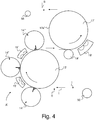
- Figure 4 is illustrative of a second variant of a device designed to fill the opening 10 formed into the security paper substrate 1 with transparent polymer material 2.
- This device can suitably be located downstream of a laminating system (not shown) - such as discussed e.g. in International ( PCT) Publication No. WO 2008/104904 A1 - that is designed to laminate the transparent film 5, respectively 5*, onto the first side I of the security paper substrate 1 in such a way as to close one end of the opening 10 formed in the security paper substrate 1 as discussed above.
- the device of Figure 4 is in particular designed to be located prior to cutting of the laminated film 5, respectively 5*.
- the laminated film 5, respectively 5* is cut subsequent to the application of the transparent polymer material 2 into the opening 10 formed into the security paper substrate 1.
- Cutting of the laminated film is once again preferably carried out by means of a laser beam designated schematically by reference B in Figure 4 .
- cutting of the laminated film can again be carried out in accordance with the teaching of International ( PCT) Publication No. WO 2010/001317 A1 .
- Reference numeral 50 in Figure 4 likewise schematically illustrates an output of the laminating system (upstream of the location where the laminated film 5, respectively 5*, is cut), while reference numeral 55 schematically illustrates an accelerating drum used to separate the sheets subsequent to the application of the transparent polymer material 2.
- Components 13', 14' (as well as 14" and 14'"), 17', 18', 19' have the same purpose as components 13, 14, 17, 18, 19 of Figure 3 .
- the application system A' of the device of Figure 4 includes multiple application units 14', 14", 14'" (advantageously designed as screen-printing units) which are each adapted to apply a portion of the transparent polymer material 2 necessary to fill the opening 10.
Description
- The present invention generally relates to the creation of a transparent polymer window with a field of lenses in a security paper substrate.
- The lamination of transparent films onto a side of a security paper substrate is known from International (
PCT) Publications Nos. WO 2008/104904 A1 WO 2009/112989 A1 WO 2010/001317 A1 -
DE 10 2011 108 477 A1 discloses a security element for securing value objects with a substrate with a window containing at least one hollow chamber passing through the substrate, wherein the at least one hollow chamber is filled with a filling material with a security feature, the at least one hollow chamber is covered on both sides of the substrate respectively with one at least partially light-transmissive cover foil, and that the at least one hollow chamber has a hollow chamber depth defined by the substrate thickness at the edge of the hollow chamber, lying between 0.5 µm and 140 µm, wherein the substrate is a paper substrate. -
DE 10 2009 048 145 A1 discloses a data carrier, especially a value or security document, having a window that extends from a bottom to a top of the data carrier, a foil element having a security element that covers the window on the top of the data carrier, one portion of the security element lying over the window and one portion of the security element next to the window, wherein the portion of the security element that lies over the window exhibits a radiation modification region, wherein the radiation modification region is in register with the window and wherein in the radiation modification region the visual appearance of the security element is modified by the action of electromagnetic radiation. -
DE 10 2004 026 050 A1 relates to security paper comprising a transparently filled area for the production of valuable documents such as bank notes, cheques, cheque cards, passports or shares. Said paper comprises at least one first layer consisting of an essentially non-transparent material, at least one first opening that penetrates the first layer of essentially non-transparent material, a filling in the first opening that is at least transparent in some areas and agents for fixing the filling in situ.DE 10 2004 026 050 A1 -
US 2006/236877 A1 discloses an apparatus for producing a microreplicated article. This apparatus includes a first patterned roll having a first diameter and a second patterned roll having a second diameter. A drive assembly is included and is configured to rotate the first patterned roll and the second patterned roll such that the first and second rolls maintain a continuous registration within about 100 micrometers. The second diameter is 0.01 to 1 percent larger than the first diameter. A method of making a microreplicated article is also disclosed. - Further improvements of these known solutions are required, especially with a view to create a transparent polymer window with a field of lenses in the security paper substrate.
- A general aim of the invention is therefore to improve the solutions of the prior art.
- More specifically, an aim of the present invention is to provide such a solution that can suitably allow for the creation of a transparent polymer window with a field of lenses in a security paper substrate.
- These aims are achieved thanks to the solutions recited in the claims.
- In particular, there is claimed a method of creating a transparent polymer window with a field of lenses in a security paper substrate, the features of which are recited in
independent claims - There is also claimed a device designed to fill an opening formed into a security paper substrate with transparent polymer material, which opening is closed at one end by a transparent film that is laminated onto a first side of the security paper substrate, the features of which device are recited in independent claim 8. Further advantageous embodiments of this device form the subject-matter of the dependent claims.
- There is also claimed a processing machine comprising (i) a laminating system designed to laminate a transparent film onto a first side of the security paper substrate in such a way as to close one end of an opening formed into a security paper substrate and (ii) a device in accordance with the invention designed to fill the opening with transparent polymer material.
- Further advantageous embodiments of the invention are discussed below.
- Other features and advantages of the present invention will appear more clearly from reading the following detailed description of embodiments of the invention which are presented solely by way of non-restrictive examples and illustrated by the attached drawings in which:
-
Figures 1A-D are schematic sectional views illustrating successive steps of an embodiment of a method of creating a transparent polymer window with a field of lenses in a security paper substrate in accordance with a first embodiment of the invention ; -
Figures 2A-E are schematic sectional views illustrating successive steps of an embodiment of a method of creating a transparent polymer window with a field of lenses in a security paper substrate in accordance with a second embodiment of the invention ; -
Figure 3 is a schematic side view of a device designed to fill an opening formed into a security paper substrate with transparent polymer material, which opening is closed at one end by a transparent film that is laminated onto a first side of the security paper, in accordance with a first variant of the invention ; and -
Figure 4 is a schematic side view of a device designed to fill an opening formed into a security paper substrate with transparent polymer material, which opening is closed at one end by a transparent film that is laminated onto a first side of the security paper, in accordance with a second variant of the invention. - The present invention will be described in the particular context of the creation of transparent polymer windows into security paper substrates which are provided in the form of successive sheets, the security paper substrates being provided with an opening which is closed at one end by a transparent film that is laminated onto a first side of the security paper substrate.
- As such, the formation of transparent windows by punching or cutting a hole (for instance by laser cutting) into security paper sheets followed by the lamination of a transparent film onto a first side of the security paper sheets so as to close one end of the opening is known from International (
PCT) Publications Nos. WO 2008/104904 A1 WO 2009/112989 A1 WO 2010/001317 A1 - This process is schematically illustrated by
Figures 1A-C and2A-C in the context of two distinct embodiments of the invention. - In accordance with a first embodiment of the invention as illustrated by
Figures 1A-D , thesecurity paper substrate 1 is first provided with anopening 10, namely a through-hole. This can be performed by punching or cutting (for instance by means of a suitable mechanical cutting tool or by means of a laser beam) a hole through the thickness of thesecurity paper substrate 1. Thisopening 10 can exhibit any desired shape and/or dimensions. Theopening 10 is then closed at one end by atransparent film 5 that is laminated onto a first side I of thesecurity paper substrate 1 as illustrated byFigure 1C , which lamination can be performed according to the principle taught by International (PCT) Publications Nos. WO 2008/104904 A1 WO 2009/112989 A1 WO 2010/001317 A1 - According to this first embodiment, the
transparent film 5 is already provided with a field of lenses L and thetransparent film 5 is laminated in such a way as to close theopening 10 and form the lenses L on the first side I of thesecurity paper substrate 1 in register with the opening 10. The lenses L can exhibit any desired shape and may for instance consist of a parallel arrangement of semi-cylindrical lenses or a two-dimensional array of individual lens elements, such as hemispherical or hexagonal lenses. - Subsequent to the lamination of the
transparent film 5, theopening 10 is filled withtransparent polymer material 2. Thistransparent polymer material 2 is a UV-curable polymer material which is cured by UV radiation, in this first embodiment, from a second side II of thesecurity paper substrate 1, opposite to the first side I. - As a result of the filling of the
opening 10 with thetransparent polymer material 2 there is formed a transparent polymer window W in the security paper substrate which exhibits a thickness T (including the lenses L) in the order of magnitude of the thickness of thesecurity paper substrate 1. Thesecurity paper substrate 1 thus provided with the transparent polymer window W can suitably be printed on the second side II with patterns, in register with the lenses L, so as to interact with the lenses L and form an optically-variable security feature that is observable through the window W and lenses L, from the first side Iof thesecurity paper substrate 1. -
Figures 2A-E illustrate a second embodiment of the invention wherein thesecurity paper substrate 1 is first provided, like in the first embodiment, with an opening 10 (Figure 2B ) which is then closed at one end by atransparent film 5* that is laminated onto a first side I of the security paper substrate 1 (Figure 2C ). In contrast to the first embodiment, thetransparent film 5* is not provided with any lenses L. - Subsequent to the lamination of the
transparent film 5*, theopening 10 is likewise filled withtransparent polymer material 2. In contrast to the first embodiment, thetransparent polymer material 2 is subjected to a further processing step as illustrated byFigure 2D which consists in the replication of a field of lenses L into thetransparent polymer material 2 applied in theopening 10 in such a way as to form lenses L on a second side II of thesecurity paper substrate 1, opposite to the first side I, in register with theopening 10. - The replication of the lenses L into the
transparent polymer material 2 is preferably carried out by pressing the second side of thesecurity paper substrate 1, in the area of thetransparent polymer material 2, against a lens replicating medium which is schematically illustrated inFigure 2D and designated byreference numeral 17a, respectively 17a'. Thislens replicating medium transparent polymer material 2. - Like in the first embodiment, the
transparent polymer material 2 is a UV-curable polymer material. In this other embodiment, thetransparent polymer material 2 is however cured by UV radiation from the first side I of thesecurity paper substrate 1 through thetransparent film 5*, while thesecurity paper substrate 1 is in contact with a surface of thelens replicating medium Figure 2D ). - As a result of the filling of the
opening 10 with thetransparent polymer material 2 there is formed a transparent polymer window W in the security paper substrate which exhibits a thickness T (including the lenses L) in the order of magnitude of the thickness of thesecurity paper substrate 1. In contrast to the first embodiment, the lenses L are formed on the second side II of thesecurity paper substrate 1. Thesecurity paper substrate 1 thus provided with the transparent polymer window W can suitably be printed on the first side I with patterns, in register with the lenses L, so as to interact with the lenses L and form an optically-variable security feature that is observable through the window W and lenses L, from the second side IIof thesecurity paper substrate 1. - As this will be appreciated hereinafter, the
transparent polymer material 2 is preferably applied by screen-printing using one or more screen-printing units as application unit(s). More than one application units may be necessary in order to suitably applytransparent polymer material 2 in a quantity sufficient to fill theopening 10. - The lenses L preferably have a lens pitch PL of the order of 10 to 50 µm and a lens height hL of the order of 10 to 20 µm. In comparison, the overall thickness T of the security paper substrate is of the order of 60 to 120 µm.
-
Figure 3 is illustrative of a first variant of a device designed to fill theopening 10 formed into thesecurity paper substrate 1 withtransparent polymer material 2. This device can suitably be located downstream of a laminating system (not shown) - such as discussed e.g. in International (PCT) Publication No. WO 2008/104904 A1 transparent film 5, respectively 5*, onto the first side I of thesecurity paper substrate 1 in such a way as to close one end of theopening 10 formed in thesecurity paper substrate 1 as discussed above. - The device of
Figure 3 is in particular designed to be located after cutting of thelaminated film 5, respectively 5*, which is preferably cut by means of a laser beam designated schematically by reference B inFigure 3 . Cutting of the laminated film is preferably carried out in accordance with the teaching of International (PCT) Publication No. WO 2010/001317 A1 Reference numeral 50 inFigure 3 schematically illustrates an output of the laminating system (upstream of the location where thelaminated film 5, respectively 5*, is cut), whilereference numeral 55 schematically illustrates an accelerating drum used to separate the sheets prior to applying thetransparent polymer material 2. - In the context of
Figure 3 , thesecurity paper substrate 1 is transferred to an application system A comprising afirst cylinder 13 which supports the first side I of thesecurity paper substrate 1. This application system A further comprises afirst application unit 14 designed to cooperate with thefirst cylinder 13 and the second side II of thesecurity paper substrate 1 in order to apply thetransparent polymer material 2 in theopening 10 formed in thesecurity paper substrate 1. Thisapplication unit 14 is preferably designed as a screen-printing unit. A suitable screen-printing unit is for instance disclosed in European Patent Publication No.EP 0 723 864 A1 in the name of the present Applicant, which is incorporated herein by reference in its entirety. - Downstream of the
first cylinder 13, there is provided asecond cylinder 17 which cooperates with the second side II of thesecurity paper substrate 1. Thissecond cylinder 17 carries on its circumference a lens replicating medium 17a (as schematically illustrated inFigure 2D ) designed to replicate a field of lenses L into thetransparent polymer material 2 applied in theopening 10 as discussed above. Theapplication unit 14 may be adapted to supply a slight excess oftransparent polymer material 2 sufficient to fill the recessed portion of the lens replicating medium 17a. - A
pressure roller 18 is advantageously further provided in order to cooperate with the first side I of thesecurity paper substrate 1 and press thesecurity paper substrate 1 against the circumference of thesecond cylinder 17, thereby ensuring proper replication of the lenses L into thetransparent polymer material 2. - The device further comprises a UV-curing
unit 19 cooperating with thesecond cylinder 17 in order to cure the UV-curable polymer material 2 from the first side I of thesecurity paper substrate 1, through the transparent film, while thesecurity paper substrate 1 is in contact with the lens replicating medium 17a. - Subsequent to the replication of the lenses L, the
security paper substrate 1 is transferred to a suitablesheet gripper system 60 comprising, as is conventional in the art, a pair ofendless chains 62 carrying spaced-apart gripper bars, whichendless chains 62 are driven into rotation between pairs of chain wheels, one pair being illustrated inFigure 3 and designated byreference numeral 61. - The
second cylinder 17 with its lens replicating medium 17a may be omitted in case of formation of the transparent polymer window W in accordance with the first embodiment illustrated byFigures 1A-D . In such a case, it would be appropriate to provide the UV-curing 19 in such a way as to be associated with thefirst cylinder 13 and cure the UV-curable polymer material 2 from the second side II of thesecurity paper substrate 1. -
Figure 4 is illustrative of a second variant of a device designed to fill theopening 10 formed into thesecurity paper substrate 1 withtransparent polymer material 2. This device can suitably be located downstream of a laminating system (not shown) - such as discussed e.g. in International (PCT) Publication No. WO 2008/104904 A1 transparent film 5, respectively 5*, onto the first side I of thesecurity paper substrate 1 in such a way as to close one end of theopening 10 formed in thesecurity paper substrate 1 as discussed above. - The device of
Figure 4 is in particular designed to be located prior to cutting of thelaminated film 5, respectively 5*. InFigure 4 , thelaminated film 5, respectively 5*, is cut subsequent to the application of thetransparent polymer material 2 into theopening 10 formed into thesecurity paper substrate 1. Cutting of the laminated film is once again preferably carried out by means of a laser beam designated schematically by reference B inFigure 4 . In essence, cutting of the laminated film can again be carried out in accordance with the teaching of International (PCT) Publication No. WO 2010/001317 A1 Reference numeral 50 inFigure 4 likewise schematically illustrates an output of the laminating system (upstream of the location where thelaminated film 5, respectively 5*, is cut), whilereference numeral 55 schematically illustrates an accelerating drum used to separate the sheets subsequent to the application of thetransparent polymer material 2. - In contrast to the variant of
Figure 3 , it should therefore be appreciated that thesecurity paper substrate 1 is fed through the device while individual sheets of thesecurity paper substrate 1 are still linked to one another by the transparent film that is laminated onto thesecurity paper substrate 1. Sheets ofsecurity paper substrate 1 are separated at the downstream end of the device illustrated inFigure 4 . - Components 13', 14' (as well as 14" and 14'"), 17', 18', 19' have the same purpose as
components Figure 3 . - In contrast to the device of
Figure 3 , the application system A' of the device ofFigure 4 includesmultiple application units 14', 14", 14'" (advantageously designed as screen-printing units) which are each adapted to apply a portion of thetransparent polymer material 2 necessary to fill theopening 10. In this case, it may be appropriate to further provide intermediate UV-curingunits 15', 15" between the first andsecond application units 14', 14" and between the second andthird application units 14", 14"'. - Various modifications and/or improvements may be made to the above-described embodiments without departing from the scope of the invention as defined by the annexed claims.
- In particular, it may be appropriate to further provide an additional application unit cooperating directly with the circumference of the
second cylinder 17, 17' ofFigures 3 and4 , upstream of the location where thesecurity paper substrate 1 is contacting thesecond cylinder 17, 17' so as to apply a small amount oftransparent polymer material 2 in the recessed portion of the lens replicating medium 17a, 17a'. -
- 1
- security paper substrate
- I
- first side of
security paper substrate 1 - II
- second side of
security paper substrate 1, opposite to the first side I - T
- thickness of security paper substrate 1 (in the range of 60 to 120 µm)
- W
- transparent polymer window formed in
security paper substrate 1 - L
- field of lenses formed onto window W (in register with opening 10)
- PL
- lens pitch (spacing between adjacent lenses - preferably in the range of 10 to 50 µm)
- hL
- lens height (preferably in the range of 10 to 20 µm)
- 2
- transparent polymer material (in particular UV-curable polymer material) used to fill the
opening 10 formed into thesecurity paper substrate 1 - 5
- transparent film laminated onto first side I of security paper substrate 1 (first embodiment -
Figures 1A-D ) / transparent film carrying field of lenses L - 5*
- transparent film laminated onto first side I of security paper substrate 1 (second embodiment -
Figures 2A-E ) - 10
- opening (through-hole) formed into thickness of
security paper substrate 1 - A
- application system (first variant -
Figure 3 ) - 13
- cylinder cooperating with
application unit 14 and supporting first side I of security paper substrate 1 (first variant -Figure 3 ) - 14
- application unit, in particular screen-printing unit (first variant -
Figure 3 ) - 17
- lens replicating cylinder (second cylinder) carrying at least one lens replicating medium 17a on its circumference and cooperating with the second side II of the security paper substrate 1 (first variant -
Figure 3 ) - 17a
- lens replicating medium (e.g. lens replicating plate) carried by
lens replicating cylinder 17 - 18
- pressure roller cooperating with the first side I of the
security paper substrate 1 and pressing the security paper substrate against the circumference of thelens replicating cylinder 17 - 19
- UV-curing unit cooperating with the
lens replicating cylinder 17 to cure the UV-curable polymer material 2 from the first side I of thesecurity paper substrate 1, through thetransparent film 5* - A'
- application system (second variant -
Figure 4 ) - 13'
- (first) cylinder cooperating with
application units 14', 14", 14'" and supporting first side I of security paper substrate 1 (second variant -Figure 4 ) - 14'
- (first) application unit, in particular screen-printing unit (second variant -
Figure 4 ) - 14"
- (second) application unit, in particular screen-printing unit (second variant -
Figure 4 ) - 14'"
- (third) application unit, in particular screen-printing unit (second variant -
Figure 4 ) - 15'
- intermediate UV-curing unit located between first and
second application units 14', 14" - 15"
- intermediate UV-curing unit located between second and
third application units 14", 14'" - 17'
- lens replicating cylinder (second cylinder) carrying at least one lens replicating medium 17a' on its circumference and cooperating with the second side II of the security paper substrate 1 (second variant -
Figure 4 ) - 17a'
- lens replicating medium (e.g. lens replicating plate) carried by lens replicating cylinder 17'
- 18'
- pressure roller cooperating with the first side I of the
security paper substrate 1 and pressing the security paper substrate against the circumference of the lens replicating cylinder 17' - 19'
- UV-curing unit cooperating with the lens replicating cylinder 17' to cure the UV-
curable polymer material 2 from the first side I of thesecurity paper substrate 1, through thetransparent film 5* - 50
- output of film laminating machine (e.g. OptiNota® H machine with OptiWindows® module - see e.g.
WO 2008/104904 A1 ,WO 2009/112989 A1 andWO 2010/001317 A1 ) - B
- laser beam for cutting laminated film (see e.g.
WO 2008/104904 A1 ,WO 2009/112989 A1 andWO 2010/001317 A1 ) - 55
- accelerating drum for separating the sheets
- 60
- sheet gripper system
- 61
- chain wheel of
sheet gripper system 60 - 62
- endless chains of
sheet gripper system 60
Claims (13)
- A method of creating a transparent polymer window (W) with a field of lenses (L) in a security paper substrate (1), the method comprising the following steps :- providing a security paper substrate (1) ;- forming an opening (10) into the security paper substrate (1) ;- laminating a transparent film (5) which comprises a field of lenses (L) onto a first side (I) of the security paper substrate (1) in such a way as to close the opening (10) at one end and form lenses (L) on the first side (I) of the security paper substrate (1) in register with the opening (10) ; and- filling the opening (10) with transparent polymer material (2),wherein the transparent polymer material (2) is a UV-curable polymer material and wherein the UV-curable polymer material (2) is cured from a second side (II) of the security paper substrate (1), opposite to the first side (I).
- A method of creating a transparent polymer window (W) with a field of lenses (L) in a security paper substrate (1), the method comprising the following steps :- providing a security paper substrate (1) ;- forming an opening (10) into the security paper substrate (1) ;- laminating a transparent film (5*) onto a first side (I) of the security paper substrate (1) in such a way as to close the opening (10) at one end ;- filling the opening (10) with transparent polymer material (2) ; and- replicating a field of lenses (L) into the transparent polymer material (2) applied in the opening (10) in such a way as to form lenses (L) on a second side (II) of the security paper substrate (1), opposite to the first side (I), in register with the opening (10),wherein the transparent polymer material (2) is a UV-curable polymer material and wherein the UV-curable polymer material (2) is cured from the first side (I) of the security paper substrate (1), through the transparent film (5*).
- The method according to claim 1 or 2, wherein the opening (10) is formed by punching a hole into the security paper substrate (1) or by cutting a hole into the security paper substrate (1).
- The method according to claim 3, wherein the opening (10) is formed by means of a mechanical cutting tool or by means of a laser beam.
- The method according to claim 2, wherein the UV-curable polymer material (2) is cured during the replicating step, while the second side (II) of the security paper substrate (1) is in a contact with a surface of a lens replicating medium (17a; 17a').
- The method according to any one of the preceding claims, wherein the transparent polymer material (2) is applied by means of a least one application unit (14; 14', 14", 14'").
- The method according to claim 6, wherein the transparent polymer material (2) is applied by means of one or more screen-printing units acting as the least one application unit (14; 14', 14", 14'").
- A device designed to fill an opening (10) formed into a security paper substrate (1) with transparent polymer material (2), which opening (10) is closed at one end by a transparent film (5*) that is laminated onto a first side (I) of the security paper substrate (1), the device comprising an application system (A; A') including a first cylinder (13; 13') supporting the first side (I) of the security paper substrate (1) and at least a first application unit (14; 14') cooperating with a second side (II) of the security paper substrate (1), opposite to the first side (I), to apply the transparent polymer material (2) into the opening (10) while the security paper substrate (1) is being supported by the first cylinder (13; 13'),
wherein the device further comprises a second cylinder (17; 17') located downstream of the first cylinder (13; 13'), which second cylinder (17; 17') cooperates with the second side (II) of the security paper substrate (1) and carries on its circumference a lens replicating medium (17a; 17a') designed to replicate a field of lenses (L) into the transparent polymer material (2) applied in the opening (10) in such a way as to form lenses (L) on the second side (II) of the security paper substrate (1) in register with the opening (10),
and wherein the transparent polymer material (2) is a UV-curable polymer material, the device further comprising a UV-curing unit (19; 19') cooperating with the second cylinder (17; 17') in order to cure the UV-curable polymer material (2) from the first side (I) of the security paper substrate (1), through the transparent film (5*). - The device according to claim 8, further comprising a pressure roller (18; 18') cooperating with the first side (I) of the security paper substrate (1) and pressing the security paper substrate (1) against the circumference of the second cylinder (17; 17').
- The device according to claim 8 or 9, wherein the application system (A') further includes at least a second application unit (14", 14'") cooperating with the second side (II) of the security paper substrate (1) to apply the transparent polymer material (2) into the opening (10) while the security paper substrate (1) is being supported by the first cylinder (13'), and wherein each of the first and second application units (14', 14", 14'") applies a portion of the transparent polymer material (2) necessary to fill the opening (10).
- The device according to claim 10, wherein the transparent polymer material (2) is a UV-curable polymer material, the device further comprising at least one intermediate UV-curing unit (15', 15") located between the at least first and second application units (14', 14", 14'")
- The device according to any one of claims 8 to 11, wherein each application unit (14; 14', 14", 14'") is a screen-printing unit.
- A processing machine comprising :- a laminating system designed to laminate a transparent film (5; 5*) onto a first side (I) of the security paper substrate (1) in such a way as to close one end of an opening (10) formed into a security paper substrate (1) ; and- a device in accordance with any one of claims 8 to 12 designed to fill the opening (10) with transparent polymer material (2).
Priority Applications (1)
| Application Number | Priority Date | Filing Date | Title |
|---|---|---|---|
| EP14780598.0A EP3033232B1 (en) | 2013-08-14 | 2014-08-08 | Creation of a transparent polymer window with a field of lenses in a security paper substrate |
Applications Claiming Priority (3)
| Application Number | Priority Date | Filing Date | Title |
|---|---|---|---|
| EP13180397 | 2013-08-14 | ||
| EP14780598.0A EP3033232B1 (en) | 2013-08-14 | 2014-08-08 | Creation of a transparent polymer window with a field of lenses in a security paper substrate |
| PCT/IB2014/063806 WO2015022612A1 (en) | 2013-08-14 | 2014-08-08 | Creation of a transparent polymer window with a field of lenses in a security paper substrate |
Publications (2)
| Publication Number | Publication Date |
|---|---|
| EP3033232A1 EP3033232A1 (en) | 2016-06-22 |
| EP3033232B1 true EP3033232B1 (en) | 2018-10-31 |
Family
ID=48979648
Family Applications (1)
| Application Number | Title | Priority Date | Filing Date |
|---|---|---|---|
| EP14780598.0A Not-in-force EP3033232B1 (en) | 2013-08-14 | 2014-08-08 | Creation of a transparent polymer window with a field of lenses in a security paper substrate |
Country Status (12)
| Country | Link |
|---|---|
| US (1) | US10654256B2 (en) |
| EP (1) | EP3033232B1 (en) |
| JP (1) | JP6454343B2 (en) |
| KR (1) | KR20160042125A (en) |
| CN (1) | CN105451995B (en) |
| AU (1) | AU2014307636B2 (en) |
| BR (1) | BR112016002817A2 (en) |
| CA (1) | CA2919796A1 (en) |
| MX (1) | MX2016001966A (en) |
| PH (1) | PH12016500305A1 (en) |
| RU (1) | RU2665521C2 (en) |
| WO (1) | WO2015022612A1 (en) |
Families Citing this family (12)
| Publication number | Priority date | Publication date | Assignee | Title |
|---|---|---|---|---|
| EP2767395A1 (en) * | 2013-02-15 | 2014-08-20 | KBA-NotaSys SA | Substrate for security papers and method of manufacturing the same |
| CN105917049B (en) | 2014-01-16 | 2019-08-02 | 卡巴-诺塔赛斯有限公司 | Transparency window is generated in the safety liner bottom applied for security printing |
| CN107072837A (en) | 2014-11-07 | 2017-08-18 | 宝洁公司 | Method and apparatus for manufacturing absorbent article using lasing light emitter |
| WO2017160701A1 (en) | 2016-03-15 | 2017-09-21 | The Procter & Gamble Company | Methods and apparatuses for separating and positioning discrete articles |
| EP3366474B1 (en) * | 2017-02-22 | 2020-06-24 | KBA-NotaSys SA | Printing press with in-line casting device for the replication and formation of a micro-optical structure |
| EP3401114A1 (en) | 2017-05-12 | 2018-11-14 | KBA-NotaSys SA | Security element or document and process of producing the same |
| US10411222B2 (en) * | 2017-05-23 | 2019-09-10 | University Of Maryland, College Park | Transparent hybrid substrates, devices employing such substrates, and methods for fabrication and use thereof |
| DE102017007277A1 (en) * | 2017-08-01 | 2019-02-07 | Giesecke+Devrient Mobile Security Gmbh | Data page made of hybrid material |
| US10479128B2 (en) * | 2017-10-27 | 2019-11-19 | Assa Abloy Ab | Security feature |
| DE102020108080A1 (en) | 2020-03-24 | 2021-09-30 | Koenig & Bauer Ag | Method for producing a security feature effective as a see-through register on a security document, method for producing security documents and security document |
| DE102020108081A1 (en) | 2020-03-24 | 2021-09-30 | Koenig & Bauer Ag | Method for producing a security feature effective as a see-through register on a security document and a security document with a security feature effective as a see-through register on a security document |
| TWI749843B (en) * | 2020-11-03 | 2021-12-11 | 南亞塑膠工業股份有限公司 | Security paper |
Family Cites Families (13)
| Publication number | Priority date | Publication date | Assignee | Title |
|---|---|---|---|---|
| US5671671A (en) | 1995-01-24 | 1997-09-30 | De La Rue Giori S.A. | Rotary screen printing machine for sheet printing |
| DE102004026050A1 (en) | 2004-05-25 | 2005-12-15 | Giesecke & Devrient Gmbh | security paper |
| US20060023687A1 (en) * | 2004-07-27 | 2006-02-02 | Telefonaktiebolaget Lm Ericsson (Publ) | Fast reliable downlink signaling to support enhanced uplink services in a communication system |
| DE102005028162A1 (en) * | 2005-02-18 | 2006-12-28 | Giesecke & Devrient Gmbh | Security element for protecting valuable objects, e.g. documents, includes focusing components for enlarging views of microscopic structures as one of two authenication features |
| MX2007010816A (en) * | 2005-03-09 | 2007-11-07 | 3M Innovative Properties Co | Apparatus and method for making microreplicated article. |
| DE102005062132A1 (en) * | 2005-12-23 | 2007-07-05 | Giesecke & Devrient Gmbh | Security unit e.g. seal, for e.g. valuable document, has motive image with planar periodic arrangement of micro motive units, and periodic arrangement of lens for moire magnified observation of motive units |
| EP1842665A1 (en) * | 2006-04-04 | 2007-10-10 | Kba-Giori S.A. | Process for producing security papers, intaglio printing press for implementing said process, and security paper produced according to said process |
| EP1961578A1 (en) | 2007-02-26 | 2008-08-27 | Kba-Giori S.A. | Method and installation for applying foil material onto successive sheets |
| EP2100736A1 (en) | 2008-03-14 | 2009-09-16 | Kba-Giori S.A. | Method and installation for applying foil material onto successive sheets |
| EP2141027A1 (en) | 2008-07-03 | 2010-01-06 | Kba-Giori S.A. | Method and installation for applying foil material onto successive sheets |
| DE102009036314A1 (en) * | 2009-08-06 | 2011-02-10 | Giesecke & Devrient Gmbh | Method for producing a security element and security element obtainable by the method |
| DE102009048145A1 (en) | 2009-10-02 | 2011-04-07 | Giesecke & Devrient Gmbh | Disk with window |
| DE102011108477A1 (en) | 2011-07-25 | 2013-01-31 | Giesecke & Devrient Gmbh | Security element with window in the substrate |
-
2014
- 2014-08-08 CA CA2919796A patent/CA2919796A1/en not_active Abandoned
- 2014-08-08 AU AU2014307636A patent/AU2014307636B2/en not_active Ceased
- 2014-08-08 JP JP2016533975A patent/JP6454343B2/en not_active Expired - Fee Related
- 2014-08-08 RU RU2016104617A patent/RU2665521C2/en not_active IP Right Cessation
- 2014-08-08 US US14/911,975 patent/US10654256B2/en active Active
- 2014-08-08 MX MX2016001966A patent/MX2016001966A/en unknown
- 2014-08-08 EP EP14780598.0A patent/EP3033232B1/en not_active Not-in-force
- 2014-08-08 WO PCT/IB2014/063806 patent/WO2015022612A1/en active Application Filing
- 2014-08-08 KR KR1020167006579A patent/KR20160042125A/en not_active Application Discontinuation
- 2014-08-08 CN CN201480044609.7A patent/CN105451995B/en not_active Expired - Fee Related
- 2014-08-08 BR BR112016002817A patent/BR112016002817A2/en not_active Application Discontinuation
-
2016
- 2016-02-15 PH PH12016500305A patent/PH12016500305A1/en unknown
Non-Patent Citations (1)
| Title |
|---|
| None * |
Also Published As
| Publication number | Publication date |
|---|---|
| US10654256B2 (en) | 2020-05-19 |
| RU2016104617A (en) | 2017-09-19 |
| AU2014307636B2 (en) | 2017-05-25 |
| CN105451995A (en) | 2016-03-30 |
| JP6454343B2 (en) | 2019-01-16 |
| EP3033232A1 (en) | 2016-06-22 |
| KR20160042125A (en) | 2016-04-18 |
| CN105451995B (en) | 2017-10-24 |
| CA2919796A1 (en) | 2015-02-19 |
| US20160200088A1 (en) | 2016-07-14 |
| WO2015022612A1 (en) | 2015-02-19 |
| PH12016500305A1 (en) | 2016-05-02 |
| AU2014307636A1 (en) | 2016-02-18 |
| MX2016001966A (en) | 2016-05-26 |
| JP2016536169A (en) | 2016-11-24 |
| RU2665521C2 (en) | 2018-08-30 |
| BR112016002817A2 (en) | 2017-08-01 |
Similar Documents
| Publication | Publication Date | Title |
|---|---|---|
| EP3033232B1 (en) | Creation of a transparent polymer window with a field of lenses in a security paper substrate | |
| EP3319809B1 (en) | Methods of manufacturing security devices and corresponding security devices and security documents | |
| EP2767395A1 (en) | Substrate for security papers and method of manufacturing the same | |
| EP3390069A1 (en) | Method for producing a security element and transfer film | |
| EP3094780B1 (en) | Creation of a transparent window in a security substrate for security printing applications | |
| CN106457874B (en) | The online manufacture of document with security element | |
| CA3098282A1 (en) | Method for producing a laminated body and a laminating film and laminated body and laminating film | |
| EP2768660B1 (en) | Method for producing micro-concave mirrors | |
| AU2017101236A4 (en) | Method of embossing micro-structures on a substrate | |
| US7192641B2 (en) | Stamping film, method for the production thereof and for transferring a label from said stamping film to a substrate | |
| US20190176386A1 (en) | Embossing tool and method to minimise bubble formation in embossed structures | |
| DE102008019871B3 (en) | Method for the production of multilayered security document, comprises subjecting a photopolymer foil on a first side of a carrier material and connecting the foil with the carrier material | |
| EP1457320A1 (en) | Card-shaped data carrier, method for producing the same and apparatus for producing such a card-shaped data carrier | |
| RO125841B1 (en) | Process for multiprinting of embossed micro- and nano-structures |
Legal Events
| Date | Code | Title | Description |
|---|---|---|---|
| PUAI | Public reference made under article 153(3) epc to a published international application that has entered the european phase |
Free format text: ORIGINAL CODE: 0009012 |
|
| 17P | Request for examination filed |
Effective date: 20160217 |
|
| AK | Designated contracting states |
Kind code of ref document: A1 Designated state(s): AL AT BE BG CH CY CZ DE DK EE ES FI FR GB GR HR HU IE IS IT LI LT LU LV MC MK MT NL NO PL PT RO RS SE SI SK SM TR |
|
| AX | Request for extension of the european patent |
Extension state: BA ME |
|
| DAX | Request for extension of the european patent (deleted) | ||
| STAA | Information on the status of an ep patent application or granted ep patent |
Free format text: STATUS: EXAMINATION IS IN PROGRESS |
|
| 17Q | First examination report despatched |
Effective date: 20170321 |
|
| GRAP | Despatch of communication of intention to grant a patent |
Free format text: ORIGINAL CODE: EPIDOSNIGR1 |
|
| STAA | Information on the status of an ep patent application or granted ep patent |
Free format text: STATUS: GRANT OF PATENT IS INTENDED |
|
| INTG | Intention to grant announced |
Effective date: 20180712 |
|
| GRAS | Grant fee paid |
Free format text: ORIGINAL CODE: EPIDOSNIGR3 |
|
| GRAA | (expected) grant |
Free format text: ORIGINAL CODE: 0009210 |
|
| STAA | Information on the status of an ep patent application or granted ep patent |
Free format text: STATUS: THE PATENT HAS BEEN GRANTED |
|
| AK | Designated contracting states |
Kind code of ref document: B1 Designated state(s): AL AT BE BG CH CY CZ DE DK EE ES FI FR GB GR HR HU IE IS IT LI LT LU LV MC MK MT NL NO PL PT RO RS SE SI SK SM TR |
|
| REG | Reference to a national code |
Ref country code: CH Ref legal event code: EP Ref country code: GB Ref legal event code: FG4D |
|
| REG | Reference to a national code |
Ref country code: AT Ref legal event code: REF Ref document number: 1058883 Country of ref document: AT Kind code of ref document: T Effective date: 20181115 |
|
| REG | Reference to a national code |
Ref country code: DE Ref legal event code: R096 Ref document number: 602014035188 Country of ref document: DE |
|
| REG | Reference to a national code |
Ref country code: IE Ref legal event code: FG4D |
|
| REG | Reference to a national code |
Ref country code: NL Ref legal event code: MP Effective date: 20181031 |
|
| REG | Reference to a national code |
Ref country code: LT Ref legal event code: MG4D |
|
| REG | Reference to a national code |
Ref country code: AT Ref legal event code: MK05 Ref document number: 1058883 Country of ref document: AT Kind code of ref document: T Effective date: 20181031 |
|
| PG25 | Lapsed in a contracting state [announced via postgrant information from national office to epo] |
Ref country code: PL Free format text: LAPSE BECAUSE OF FAILURE TO SUBMIT A TRANSLATION OF THE DESCRIPTION OR TO PAY THE FEE WITHIN THE PRESCRIBED TIME-LIMIT Effective date: 20181031 Ref country code: NO Free format text: LAPSE BECAUSE OF FAILURE TO SUBMIT A TRANSLATION OF THE DESCRIPTION OR TO PAY THE FEE WITHIN THE PRESCRIBED TIME-LIMIT Effective date: 20190131 Ref country code: LT Free format text: LAPSE BECAUSE OF FAILURE TO SUBMIT A TRANSLATION OF THE DESCRIPTION OR TO PAY THE FEE WITHIN THE PRESCRIBED TIME-LIMIT Effective date: 20181031 Ref country code: ES Free format text: LAPSE BECAUSE OF FAILURE TO SUBMIT A TRANSLATION OF THE DESCRIPTION OR TO PAY THE FEE WITHIN THE PRESCRIBED TIME-LIMIT Effective date: 20181031 Ref country code: BG Free format text: LAPSE BECAUSE OF FAILURE TO SUBMIT A TRANSLATION OF THE DESCRIPTION OR TO PAY THE FEE WITHIN THE PRESCRIBED TIME-LIMIT Effective date: 20190131 Ref country code: LV Free format text: LAPSE BECAUSE OF FAILURE TO SUBMIT A TRANSLATION OF THE DESCRIPTION OR TO PAY THE FEE WITHIN THE PRESCRIBED TIME-LIMIT Effective date: 20181031 Ref country code: HR Free format text: LAPSE BECAUSE OF FAILURE TO SUBMIT A TRANSLATION OF THE DESCRIPTION OR TO PAY THE FEE WITHIN THE PRESCRIBED TIME-LIMIT Effective date: 20181031 Ref country code: FI Free format text: LAPSE BECAUSE OF FAILURE TO SUBMIT A TRANSLATION OF THE DESCRIPTION OR TO PAY THE FEE WITHIN THE PRESCRIBED TIME-LIMIT Effective date: 20181031 Ref country code: IS Free format text: LAPSE BECAUSE OF FAILURE TO SUBMIT A TRANSLATION OF THE DESCRIPTION OR TO PAY THE FEE WITHIN THE PRESCRIBED TIME-LIMIT Effective date: 20190228 Ref country code: AT Free format text: LAPSE BECAUSE OF FAILURE TO SUBMIT A TRANSLATION OF THE DESCRIPTION OR TO PAY THE FEE WITHIN THE PRESCRIBED TIME-LIMIT Effective date: 20181031 |
|
| PG25 | Lapsed in a contracting state [announced via postgrant information from national office to epo] |
Ref country code: RS Free format text: LAPSE BECAUSE OF FAILURE TO SUBMIT A TRANSLATION OF THE DESCRIPTION OR TO PAY THE FEE WITHIN THE PRESCRIBED TIME-LIMIT Effective date: 20181031 Ref country code: PT Free format text: LAPSE BECAUSE OF FAILURE TO SUBMIT A TRANSLATION OF THE DESCRIPTION OR TO PAY THE FEE WITHIN THE PRESCRIBED TIME-LIMIT Effective date: 20190301 Ref country code: AL Free format text: LAPSE BECAUSE OF FAILURE TO SUBMIT A TRANSLATION OF THE DESCRIPTION OR TO PAY THE FEE WITHIN THE PRESCRIBED TIME-LIMIT Effective date: 20181031 Ref country code: SE Free format text: LAPSE BECAUSE OF FAILURE TO SUBMIT A TRANSLATION OF THE DESCRIPTION OR TO PAY THE FEE WITHIN THE PRESCRIBED TIME-LIMIT Effective date: 20181031 Ref country code: NL Free format text: LAPSE BECAUSE OF FAILURE TO SUBMIT A TRANSLATION OF THE DESCRIPTION OR TO PAY THE FEE WITHIN THE PRESCRIBED TIME-LIMIT Effective date: 20181031 Ref country code: GR Free format text: LAPSE BECAUSE OF FAILURE TO SUBMIT A TRANSLATION OF THE DESCRIPTION OR TO PAY THE FEE WITHIN THE PRESCRIBED TIME-LIMIT Effective date: 20190201 |
|
| PG25 | Lapsed in a contracting state [announced via postgrant information from national office to epo] |
Ref country code: DK Free format text: LAPSE BECAUSE OF FAILURE TO SUBMIT A TRANSLATION OF THE DESCRIPTION OR TO PAY THE FEE WITHIN THE PRESCRIBED TIME-LIMIT Effective date: 20181031 Ref country code: IT Free format text: LAPSE BECAUSE OF FAILURE TO SUBMIT A TRANSLATION OF THE DESCRIPTION OR TO PAY THE FEE WITHIN THE PRESCRIBED TIME-LIMIT Effective date: 20181031 Ref country code: CZ Free format text: LAPSE BECAUSE OF FAILURE TO SUBMIT A TRANSLATION OF THE DESCRIPTION OR TO PAY THE FEE WITHIN THE PRESCRIBED TIME-LIMIT Effective date: 20181031 |
|
| REG | Reference to a national code |
Ref country code: DE Ref legal event code: R097 Ref document number: 602014035188 Country of ref document: DE |
|
| PG25 | Lapsed in a contracting state [announced via postgrant information from national office to epo] |
Ref country code: SK Free format text: LAPSE BECAUSE OF FAILURE TO SUBMIT A TRANSLATION OF THE DESCRIPTION OR TO PAY THE FEE WITHIN THE PRESCRIBED TIME-LIMIT Effective date: 20181031 Ref country code: EE Free format text: LAPSE BECAUSE OF FAILURE TO SUBMIT A TRANSLATION OF THE DESCRIPTION OR TO PAY THE FEE WITHIN THE PRESCRIBED TIME-LIMIT Effective date: 20181031 Ref country code: SM Free format text: LAPSE BECAUSE OF FAILURE TO SUBMIT A TRANSLATION OF THE DESCRIPTION OR TO PAY THE FEE WITHIN THE PRESCRIBED TIME-LIMIT Effective date: 20181031 Ref country code: RO Free format text: LAPSE BECAUSE OF FAILURE TO SUBMIT A TRANSLATION OF THE DESCRIPTION OR TO PAY THE FEE WITHIN THE PRESCRIBED TIME-LIMIT Effective date: 20181031 |
|
| PLBE | No opposition filed within time limit |
Free format text: ORIGINAL CODE: 0009261 |
|
| STAA | Information on the status of an ep patent application or granted ep patent |
Free format text: STATUS: NO OPPOSITION FILED WITHIN TIME LIMIT |
|
| 26N | No opposition filed |
Effective date: 20190801 |
|
| PG25 | Lapsed in a contracting state [announced via postgrant information from national office to epo] |
Ref country code: SI Free format text: LAPSE BECAUSE OF FAILURE TO SUBMIT A TRANSLATION OF THE DESCRIPTION OR TO PAY THE FEE WITHIN THE PRESCRIBED TIME-LIMIT Effective date: 20181031 |
|
| PG25 | Lapsed in a contracting state [announced via postgrant information from national office to epo] |
Ref country code: TR Free format text: LAPSE BECAUSE OF FAILURE TO SUBMIT A TRANSLATION OF THE DESCRIPTION OR TO PAY THE FEE WITHIN THE PRESCRIBED TIME-LIMIT Effective date: 20181031 |
|
| PG25 | Lapsed in a contracting state [announced via postgrant information from national office to epo] |
Ref country code: LU Free format text: LAPSE BECAUSE OF NON-PAYMENT OF DUE FEES Effective date: 20190808 Ref country code: MC Free format text: LAPSE BECAUSE OF FAILURE TO SUBMIT A TRANSLATION OF THE DESCRIPTION OR TO PAY THE FEE WITHIN THE PRESCRIBED TIME-LIMIT Effective date: 20181031 |
|
| REG | Reference to a national code |
Ref country code: BE Ref legal event code: MM Effective date: 20190831 |
|
| PG25 | Lapsed in a contracting state [announced via postgrant information from national office to epo] |
Ref country code: IE Free format text: LAPSE BECAUSE OF NON-PAYMENT OF DUE FEES Effective date: 20190808 |
|
| PG25 | Lapsed in a contracting state [announced via postgrant information from national office to epo] |
Ref country code: BE Free format text: LAPSE BECAUSE OF NON-PAYMENT OF DUE FEES Effective date: 20190831 |
|
| PG25 | Lapsed in a contracting state [announced via postgrant information from national office to epo] |
Ref country code: CY Free format text: LAPSE BECAUSE OF FAILURE TO SUBMIT A TRANSLATION OF THE DESCRIPTION OR TO PAY THE FEE WITHIN THE PRESCRIBED TIME-LIMIT Effective date: 20181031 |
|
| PG25 | Lapsed in a contracting state [announced via postgrant information from national office to epo] |
Ref country code: HU Free format text: LAPSE BECAUSE OF FAILURE TO SUBMIT A TRANSLATION OF THE DESCRIPTION OR TO PAY THE FEE WITHIN THE PRESCRIBED TIME-LIMIT; INVALID AB INITIO Effective date: 20140808 Ref country code: MT Free format text: LAPSE BECAUSE OF FAILURE TO SUBMIT A TRANSLATION OF THE DESCRIPTION OR TO PAY THE FEE WITHIN THE PRESCRIBED TIME-LIMIT Effective date: 20181031 |
|
| PGFP | Annual fee paid to national office [announced via postgrant information from national office to epo] |
Ref country code: FR Payment date: 20210823 Year of fee payment: 8 |
|
| PGFP | Annual fee paid to national office [announced via postgrant information from national office to epo] |
Ref country code: DE Payment date: 20210726 Year of fee payment: 8 Ref country code: CH Payment date: 20210820 Year of fee payment: 8 Ref country code: GB Payment date: 20210823 Year of fee payment: 8 |
|
| PG25 | Lapsed in a contracting state [announced via postgrant information from national office to epo] |
Ref country code: MK Free format text: LAPSE BECAUSE OF FAILURE TO SUBMIT A TRANSLATION OF THE DESCRIPTION OR TO PAY THE FEE WITHIN THE PRESCRIBED TIME-LIMIT Effective date: 20181031 |
|
| REG | Reference to a national code |
Ref country code: DE Ref legal event code: R119 Ref document number: 602014035188 Country of ref document: DE |
|
| REG | Reference to a national code |
Ref country code: CH Ref legal event code: PL |
|
| GBPC | Gb: european patent ceased through non-payment of renewal fee |
Effective date: 20220808 |
|
| PG25 | Lapsed in a contracting state [announced via postgrant information from national office to epo] |
Ref country code: LI Free format text: LAPSE BECAUSE OF NON-PAYMENT OF DUE FEES Effective date: 20220831 Ref country code: CH Free format text: LAPSE BECAUSE OF NON-PAYMENT OF DUE FEES Effective date: 20220831 |
|
| PG25 | Lapsed in a contracting state [announced via postgrant information from national office to epo] |
Ref country code: FR Free format text: LAPSE BECAUSE OF NON-PAYMENT OF DUE FEES Effective date: 20220831 Ref country code: DE Free format text: LAPSE BECAUSE OF NON-PAYMENT OF DUE FEES Effective date: 20230301 |
|
| PG25 | Lapsed in a contracting state [announced via postgrant information from national office to epo] |
Ref country code: GB Free format text: LAPSE BECAUSE OF NON-PAYMENT OF DUE FEES Effective date: 20220808 |