EP3033119B1 - Systems for applying reduced pressure therapy - Google Patents
Systems for applying reduced pressure therapy Download PDFInfo
- Publication number
- EP3033119B1 EP3033119B1 EP14755491.9A EP14755491A EP3033119B1 EP 3033119 B1 EP3033119 B1 EP 3033119B1 EP 14755491 A EP14755491 A EP 14755491A EP 3033119 B1 EP3033119 B1 EP 3033119B1
- Authority
- EP
- European Patent Office
- Prior art keywords
- canister
- pressure
- negative pressure
- dressing
- exudate
- Prior art date
- Legal status (The legal status is an assumption and is not a legal conclusion. Google has not performed a legal analysis and makes no representation as to the accuracy of the status listed.)
- Active
Links
- 238000002560 therapeutic procedure Methods 0.000 title description 26
- 206010052428 Wound Diseases 0.000 claims description 99
- 208000027418 Wounds and injury Diseases 0.000 claims description 99
- 210000000416 exudates and transudate Anatomy 0.000 claims description 79
- 239000012530 fluid Substances 0.000 claims description 61
- 238000001514 detection method Methods 0.000 claims description 26
- 230000000694 effects Effects 0.000 claims description 23
- 238000004891 communication Methods 0.000 claims description 11
- 230000007423 decrease Effects 0.000 claims description 11
- 238000009581 negative-pressure wound therapy Methods 0.000 claims description 8
- 238000000034 method Methods 0.000 description 62
- 230000008859 change Effects 0.000 description 21
- 230000008569 process Effects 0.000 description 20
- 238000012544 monitoring process Methods 0.000 description 14
- 239000000945 filler Substances 0.000 description 9
- 239000000463 material Substances 0.000 description 9
- 238000011144 upstream manufacturing Methods 0.000 description 7
- 239000011358 absorbing material Substances 0.000 description 5
- 210000001519 tissue Anatomy 0.000 description 5
- 238000005259 measurement Methods 0.000 description 4
- 230000007246 mechanism Effects 0.000 description 4
- 229920001296 polysiloxane Polymers 0.000 description 4
- 229920001971 elastomer Polymers 0.000 description 3
- 230000035876 healing Effects 0.000 description 3
- 230000002209 hydrophobic effect Effects 0.000 description 3
- 230000035945 sensitivity Effects 0.000 description 3
- 230000000699 topical effect Effects 0.000 description 3
- 230000007704 transition Effects 0.000 description 3
- 230000000007 visual effect Effects 0.000 description 3
- OKTJSMMVPCPJKN-UHFFFAOYSA-N Carbon Chemical compound [C] OKTJSMMVPCPJKN-UHFFFAOYSA-N 0.000 description 2
- 208000034656 Contusions Diseases 0.000 description 2
- 208000002847 Surgical Wound Diseases 0.000 description 2
- 239000002250 absorbent Substances 0.000 description 2
- 230000002745 absorbent Effects 0.000 description 2
- 230000000844 anti-bacterial effect Effects 0.000 description 2
- 230000008901 benefit Effects 0.000 description 2
- 230000009519 contusion Effects 0.000 description 2
- 230000003247 decreasing effect Effects 0.000 description 2
- 230000030279 gene silencing Effects 0.000 description 2
- 208000014674 injury Diseases 0.000 description 2
- 230000037361 pathway Effects 0.000 description 2
- 239000004033 plastic Substances 0.000 description 2
- 229920003023 plastic Polymers 0.000 description 2
- 238000012545 processing Methods 0.000 description 2
- 238000007789 sealing Methods 0.000 description 2
- 230000008733 trauma Effects 0.000 description 2
- 238000012935 Averaging Methods 0.000 description 1
- 206010056340 Diabetic ulcer Diseases 0.000 description 1
- 208000035874 Excoriation Diseases 0.000 description 1
- 241000237858 Gastropoda Species 0.000 description 1
- 208000034693 Laceration Diseases 0.000 description 1
- 239000004677 Nylon Substances 0.000 description 1
- 206010030113 Oedema Diseases 0.000 description 1
- 239000004698 Polyethylene Substances 0.000 description 1
- 208000004210 Pressure Ulcer Diseases 0.000 description 1
- XUIMIQQOPSSXEZ-UHFFFAOYSA-N Silicon Chemical compound [Si] XUIMIQQOPSSXEZ-UHFFFAOYSA-N 0.000 description 1
- 208000000558 Varicose Ulcer Diseases 0.000 description 1
- 238000005299 abrasion Methods 0.000 description 1
- 230000001154 acute effect Effects 0.000 description 1
- 230000001580 bacterial effect Effects 0.000 description 1
- 230000009286 beneficial effect Effects 0.000 description 1
- 230000017531 blood circulation Effects 0.000 description 1
- 238000006243 chemical reaction Methods 0.000 description 1
- 230000001684 chronic effect Effects 0.000 description 1
- 239000011248 coating agent Substances 0.000 description 1
- 238000000576 coating method Methods 0.000 description 1
- 239000003086 colorant Substances 0.000 description 1
- 238000011340 continuous therapy Methods 0.000 description 1
- 230000002950 deficient Effects 0.000 description 1
- 230000000994 depressogenic effect Effects 0.000 description 1
- 238000011161 development Methods 0.000 description 1
- 230000009977 dual effect Effects 0.000 description 1
- 230000008020 evaporation Effects 0.000 description 1
- 238000001704 evaporation Methods 0.000 description 1
- 239000006260 foam Substances 0.000 description 1
- 208000015181 infectious disease Diseases 0.000 description 1
- 239000007788 liquid Substances 0.000 description 1
- 229920001778 nylon Polymers 0.000 description 1
- 230000003287 optical effect Effects 0.000 description 1
- 230000000737 periodic effect Effects 0.000 description 1
- 230000002093 peripheral effect Effects 0.000 description 1
- 230000035699 permeability Effects 0.000 description 1
- -1 polyethylene Polymers 0.000 description 1
- 229920000573 polyethylene Polymers 0.000 description 1
- 229920002635 polyurethane Polymers 0.000 description 1
- 239000004814 polyurethane Substances 0.000 description 1
- 229920000915 polyvinyl chloride Polymers 0.000 description 1
- 239000004800 polyvinyl chloride Substances 0.000 description 1
- 230000002035 prolonged effect Effects 0.000 description 1
- 230000000644 propagated effect Effects 0.000 description 1
- 230000001012 protector Effects 0.000 description 1
- APTZNLHMIGJTEW-UHFFFAOYSA-N pyraflufen-ethyl Chemical compound C1=C(Cl)C(OCC(=O)OCC)=CC(C=2C(=C(OC(F)F)N(C)N=2)Cl)=C1F APTZNLHMIGJTEW-UHFFFAOYSA-N 0.000 description 1
- 229910052710 silicon Inorganic materials 0.000 description 1
- 239000010703 silicon Substances 0.000 description 1
- 238000006467 substitution reaction Methods 0.000 description 1
- 230000001629 suppression Effects 0.000 description 1
- 210000001066 surgical stoma Anatomy 0.000 description 1
- 230000009772 tissue formation Effects 0.000 description 1
- 238000012546 transfer Methods 0.000 description 1
- 230000001052 transient effect Effects 0.000 description 1
- 239000012780 transparent material Substances 0.000 description 1
- 230000000472 traumatic effect Effects 0.000 description 1
- 230000001960 triggered effect Effects 0.000 description 1
- 230000035899 viability Effects 0.000 description 1
- XLYOFNOQVPJJNP-UHFFFAOYSA-N water Substances O XLYOFNOQVPJJNP-UHFFFAOYSA-N 0.000 description 1
Images


Classifications
-
- A—HUMAN NECESSITIES
- A61—MEDICAL OR VETERINARY SCIENCE; HYGIENE
- A61M—DEVICES FOR INTRODUCING MEDIA INTO, OR ONTO, THE BODY; DEVICES FOR TRANSDUCING BODY MEDIA OR FOR TAKING MEDIA FROM THE BODY; DEVICES FOR PRODUCING OR ENDING SLEEP OR STUPOR
- A61M1/00—Suction or pumping devices for medical purposes; Devices for carrying-off, for treatment of, or for carrying-over, body-liquids; Drainage systems
- A61M1/90—Negative pressure wound therapy devices, i.e. devices for applying suction to a wound to promote healing, e.g. including a vacuum dressing
- A61M1/96—Suction control thereof
-
- A61F13/05—
-
- A—HUMAN NECESSITIES
- A61—MEDICAL OR VETERINARY SCIENCE; HYGIENE
- A61M—DEVICES FOR INTRODUCING MEDIA INTO, OR ONTO, THE BODY; DEVICES FOR TRANSDUCING BODY MEDIA OR FOR TAKING MEDIA FROM THE BODY; DEVICES FOR PRODUCING OR ENDING SLEEP OR STUPOR
- A61M1/00—Suction or pumping devices for medical purposes; Devices for carrying-off, for treatment of, or for carrying-over, body-liquids; Drainage systems
- A61M1/60—Containers for suction drainage, adapted to be used with an external suction source
-
- A—HUMAN NECESSITIES
- A61—MEDICAL OR VETERINARY SCIENCE; HYGIENE
- A61M—DEVICES FOR INTRODUCING MEDIA INTO, OR ONTO, THE BODY; DEVICES FOR TRANSDUCING BODY MEDIA OR FOR TAKING MEDIA FROM THE BODY; DEVICES FOR PRODUCING OR ENDING SLEEP OR STUPOR
- A61M1/00—Suction or pumping devices for medical purposes; Devices for carrying-off, for treatment of, or for carrying-over, body-liquids; Drainage systems
- A61M1/71—Suction drainage systems
- A61M1/73—Suction drainage systems comprising sensors or indicators for physical values
- A61M1/732—Visual indicating means for vacuum pressure
-
- A—HUMAN NECESSITIES
- A61—MEDICAL OR VETERINARY SCIENCE; HYGIENE
- A61M—DEVICES FOR INTRODUCING MEDIA INTO, OR ONTO, THE BODY; DEVICES FOR TRANSDUCING BODY MEDIA OR FOR TAKING MEDIA FROM THE BODY; DEVICES FOR PRODUCING OR ENDING SLEEP OR STUPOR
- A61M1/00—Suction or pumping devices for medical purposes; Devices for carrying-off, for treatment of, or for carrying-over, body-liquids; Drainage systems
- A61M1/71—Suction drainage systems
- A61M1/78—Means for preventing overflow or contamination of the pumping systems
-
- A—HUMAN NECESSITIES
- A61—MEDICAL OR VETERINARY SCIENCE; HYGIENE
- A61M—DEVICES FOR INTRODUCING MEDIA INTO, OR ONTO, THE BODY; DEVICES FOR TRANSDUCING BODY MEDIA OR FOR TAKING MEDIA FROM THE BODY; DEVICES FOR PRODUCING OR ENDING SLEEP OR STUPOR
- A61M1/00—Suction or pumping devices for medical purposes; Devices for carrying-off, for treatment of, or for carrying-over, body-liquids; Drainage systems
- A61M1/90—Negative pressure wound therapy devices, i.e. devices for applying suction to a wound to promote healing, e.g. including a vacuum dressing
- A61M1/98—Containers specifically adapted for negative pressure wound therapy
- A61M1/982—Containers specifically adapted for negative pressure wound therapy with means for detecting level of collected exudate
-
- A—HUMAN NECESSITIES
- A61—MEDICAL OR VETERINARY SCIENCE; HYGIENE
- A61M—DEVICES FOR INTRODUCING MEDIA INTO, OR ONTO, THE BODY; DEVICES FOR TRANSDUCING BODY MEDIA OR FOR TAKING MEDIA FROM THE BODY; DEVICES FOR PRODUCING OR ENDING SLEEP OR STUPOR
- A61M1/00—Suction or pumping devices for medical purposes; Devices for carrying-off, for treatment of, or for carrying-over, body-liquids; Drainage systems
- A61M1/88—Draining devices having means for processing the drained fluid, e.g. an absorber
- A61M1/882—Draining devices provided with means for releasing antimicrobial or gelation agents in the drained fluid
-
- A—HUMAN NECESSITIES
- A61—MEDICAL OR VETERINARY SCIENCE; HYGIENE
- A61M—DEVICES FOR INTRODUCING MEDIA INTO, OR ONTO, THE BODY; DEVICES FOR TRANSDUCING BODY MEDIA OR FOR TAKING MEDIA FROM THE BODY; DEVICES FOR PRODUCING OR ENDING SLEEP OR STUPOR
- A61M2205/00—General characteristics of the apparatus
- A61M2205/15—Detection of leaks
-
- A—HUMAN NECESSITIES
- A61—MEDICAL OR VETERINARY SCIENCE; HYGIENE
- A61M—DEVICES FOR INTRODUCING MEDIA INTO, OR ONTO, THE BODY; DEVICES FOR TRANSDUCING BODY MEDIA OR FOR TAKING MEDIA FROM THE BODY; DEVICES FOR PRODUCING OR ENDING SLEEP OR STUPOR
- A61M2205/00—General characteristics of the apparatus
- A61M2205/18—General characteristics of the apparatus with alarm
-
- A—HUMAN NECESSITIES
- A61—MEDICAL OR VETERINARY SCIENCE; HYGIENE
- A61M—DEVICES FOR INTRODUCING MEDIA INTO, OR ONTO, THE BODY; DEVICES FOR TRANSDUCING BODY MEDIA OR FOR TAKING MEDIA FROM THE BODY; DEVICES FOR PRODUCING OR ENDING SLEEP OR STUPOR
- A61M2205/00—General characteristics of the apparatus
- A61M2205/33—Controlling, regulating or measuring
- A61M2205/3331—Pressure; Flow
- A61M2205/3344—Measuring or controlling pressure at the body treatment site
-
- A—HUMAN NECESSITIES
- A61—MEDICAL OR VETERINARY SCIENCE; HYGIENE
- A61M—DEVICES FOR INTRODUCING MEDIA INTO, OR ONTO, THE BODY; DEVICES FOR TRANSDUCING BODY MEDIA OR FOR TAKING MEDIA FROM THE BODY; DEVICES FOR PRODUCING OR ENDING SLEEP OR STUPOR
- A61M2205/00—General characteristics of the apparatus
- A61M2205/33—Controlling, regulating or measuring
- A61M2205/3379—Masses, volumes, levels of fluids in reservoirs, flow rates
- A61M2205/3382—Upper level detectors
-
- A—HUMAN NECESSITIES
- A61—MEDICAL OR VETERINARY SCIENCE; HYGIENE
- A61M—DEVICES FOR INTRODUCING MEDIA INTO, OR ONTO, THE BODY; DEVICES FOR TRANSDUCING BODY MEDIA OR FOR TAKING MEDIA FROM THE BODY; DEVICES FOR PRODUCING OR ENDING SLEEP OR STUPOR
- A61M2205/00—General characteristics of the apparatus
- A61M2205/75—General characteristics of the apparatus with filters
Definitions
- Embodiments of the present disclosure relate to methods (not claimed) and apparatuses for dressing and treating a wound with reduced pressure therapy or topical negative pressure (TNP) therapy.
- embodiments disclosed herein relate to negative pressure therapy devices, methods for controlling the operation of TNP systems, and methods of using TNP systems.
- Embodiments of the present disclosure relate to methods (not claimed) and apparatuses for dressing and treating a wound with reduced pressure therapy or topical negative pressure (TNP) therapy.
- embodiments disclosed herein relate to negative pressure therapy devices, methods for controlling the operation of TNP systems, and method of using TNP systems.
- Relevant prior art can be found in US 2012/078539 A1 , WO 2008/036360 A2 , GB 2 342 584 A , WO 03/101508 A2 , US 2007/032763 A1 and WO 2016/018448 A1 .
- embodiments disclosed herein relate to attachment mechanisms or systems for negative pressure therapy devices.
- a negative pressure wound therapy apparatus includes a negative pressure source configured to be in fluid communication with a wound dressing, the negative pressure source configured to provide negative pressure to the wound, a canister configured to be in fluid communication with the dressing and the negative pressure source, the canister configured to collect exudate removed from the wound, and a pressure sensor configured to monitor one or more characteristics of pressure signals generated by the negative pressure source.
- the apparatus also includes a controller configured to determine a level of exudate in the canister based at least in part on the measured one or more characteristics of the pressure signals.
- the apparatus of the preceding paragraph may also include any combination of the following features described in this paragraph, among others described herein.
- the measured one or more characteristics of the pressure signals can include magnitude of the pressure signals, and the magnitude of the pressure signals can increase as the level of exudate in the canister increases.
- the canister can include a filter configured to become occluded in order to prevent overflow of the canister and the controller can be further configured to detect a canister pre-full condition before the filter becomes occluded.
- the controller can also provide an indication of the canister pre-full condition to a user.
- the controller can be configured to determine the level of exudate in the canister based at least in part on the measured one or more characteristics of the pressure signals and a measured activity level of the negative pressure source.
- the negative pressure source can include a vacuum pump and the activity level of the negative pressure source corresponds to a speed of the vacuum pump.
- the apparatus can include a tachometer configured to measure the speed of the vacuum pump.
- the apparatus can include a fluid flow path configured to fluidically connect the dressing, the canister, and the negative pressure source, and the controller can be further configured to determine a leak rate of fluid in the flow path based at least in part on the activity level of the negative pressure source and determine the level of exudate in the canister based at least in part on the measured one or more characteristics of the pressure signals and the determined leak rate.
- the controller can be configured to remove noise from the measured one or more characteristics of the pressure signals.
- the controller can be configured to determine the level of exudate in the canister based at least in part on comparing the measured one or more characteristics of the pressure signals to one or more thresholds.
- the measured one or more characteristics can include magnitude and frequency of pressure pulses and the controller can be configured to determine the level of exudate in the canister based at least in part on the magnitude and frequency of the pressure signals.
- the magnitude of the pressure signals can increase as the level of exudate in the canister increases and the frequency of the pressure signals can decrease as the level of exudate in the canister increases.
- the apparatus of any of the preceding paragraphs may also include any combination of the following features described in this paragraph, among others described herein.
- the controller can be configured to determine the level of exudate in the canister irrespective of an intensity of a leak present in a fluid flow path configured to fluidically connect the dressing, the canister, and the negative pressure source.
- the controller can be configured to determine the level of exudate in the canister based at least in part on a change in the measured one or more characteristics of the pressure signals.
- the apparatus can include a wound dressing configured to be placed over a wound.
- a method of operating a negative pressure wound therapy apparatus includes monitoring pressure signals generated by a negative pressure source in fluid communication with a wound dressing and a canister and determining a level of aspirated exudate in the canister based at least in part on one or more characteristics of the monitored pressure signals.
- One or more characteristics of the monitored pressure signals can include magnitude of the pressure signals, and the magnitude of the pressure signals can increase as the level of exudate in the canister increases.
- the canister can include a filter configured to become occluded in order to prevent overflow of the canister and the method can further include detecting a canister pre-full condition before the filter becomes occluded. An indication of the canister pre-full condition can be provided to a user.
- the method can include measuring activity level of the negative pressure source and determining the level of exudate in the canister based at least in part on the one or more characteristics of the monitored pressure signals and the measured activity level.
- the negative pressure source can include a vacuum pump and the activity level of the negative pressure source corresponds to a speed of the vacuum pump.
- a tachometer can used to measure the speed of the vacuum pump.
- the method can include determining a leak rate of fluid in a flow path based at least in part on the activity level of the negative pressure source and determining the level of exudate in the canister based at least in part on the one or more characteristics of the monitored pressure signals and the determined leak rate.
- the fluid flow path can fluidically connect a dressing placed over a wound, the negative pressure source, and the canister.
- the method of any of the preceding paragraphs may also include any combination of the following features described in this paragraph, among others described herein.
- the method can include removing noise from the pressure signal measurements.
- the method can include determining the level of exudate in the canister based at least in part on comparing the one or more characteristics of the monitored pressure signals to one or more thresholds.
- the one or more characteristics of the monitored pressure signals can include magnitude and frequency of the pressure signals and the method can further include determining the level of exudate in the canister based at least in part on the magnitude and the frequency of the monitored pressure signals.
- the magnitude of the pressure signals can increase as the level of exudate in the canister increases and the frequency of the pressure signals can decrease as the level of exudate in the canister increases.
- Determining the level of aspirated exudate in the canister is performed irrespective of an intensity of a leak present in a fluid flow fluidically connecting the dressing, the canister, and the negative pressure source.
- the method can include determining the level of exudate in the canister based at least in part on a change in the one or more characteristics of the monitored pressure signals.
- a negative pressure wound therapy apparatus in various (not claimed) embodiments, includes a dressing configured to be placed over a wound, the dressing configured to collect exudate removed from the wound, a negative pressure source configured to be in fluid communication with the dressing, the negative pressure source configured to provide negative pressure to the wound, and a pressure sensor configured to monitor one or more characteristics of pressure signals generated by the negative pressure source.
- the apparatus also includes a controller configured to determine a level of exudate in the dressing based at least in part on the monitored one or more characteristics of the pressure signals.
- the apparatus of any of the preceding paragraphs may also include any combination of the following features described in this paragraph, among others described herein.
- the monitored one or more characteristics of the pressure signals can include magnitude of the pressure signals, and the magnitude of the pressure signals can increase as the level of exudate in the dressing increases.
- the dressing can include a filter configured to become occluded in order to prevent overflow and the controller can be further configured to detect a dressing pre-full condition before the filter becomes occluded and provide an indication of the dressing pre-full condition to a user.
- the controller can be further configured to determine the level of exudate in the dressing based at least in part on the monitored one or more characteristics of the pressure signals and a measured activity level of the negative pressure source.
- the apparatus can further include a fluid flow path configured to fludicially connect the dressing and the negative pressure source and the controller can be further configured to determine a leak rate of fluid in the flow path based at least in part on the activity level of the negative pressure source and to determine the level of exudate in the dressing based at least in part on the monitored one or more characteristics of the pressure signals and the determined leak rate.
- the apparatus of any of the preceding paragraphs may also include any combination of the following features described in this paragraph, among others described herein.
- the controller can be configured to determine the level of exudate in the dressing based at least in part on comparing the monitored one or more characteristics of the pressure signals to one or more thresholds
- the monitored one or more characteristics of the pressure signals can include magnitude and frequency of the pressure signals and the controller can be further configured to determine the level of exudate in the dressing based at least in part on the magnitude and the frequency of the pressure signals.
- the magnitude of the pressure signals can increase as the level of exudate in the dressing increases and the frequency of the pressure signals can decrease as the level of exudate in the dressing increases.
- the controller can be configured to determine the level of exudate in the dressing irrespective of an intensity of a leak present in a fluid flow path configured to fluidically connect the dressing and negative pressure source.
- the controller can be configured to determine the level of exudate in the dressing based at least in part on a change in the monitored one or more characteristics of the pressure signals.
- a method of operating a negative wound therapy apparatus includes monitoring pressure signals generated by a negative pressure source in fluid communication with a wound dressing and a canister and determining a level of aspirated exudate in the dressing based at least in part on one or more characteristics of the monitored pressure signals.
- the method of any of the preceding paragraphs may also include any combination of the following features described in this paragraph, among others described herein.
- the monitored one or more characteristics of the pressure signals include magnitude of the pressure signals, and wherein the magnitude of the pressure signals increases as the level of exudate in the dressing increases.
- the dressing can include a filter configured to become occluded in order to prevent overflow and the method can further include detecting a dressing pre-full condition before the filter becomes occluded and providing an indication of the dressing pre-full condition to a use.
- the method can further include measuring activity level of the negative pressure source and determining the level of exudate in the dressing based at least in part on the monitored one or more characteristics of the pressure signals and the measured activity level.
- the method of any of the preceding paragraphs may also include any combination of the following features described in this paragraph, among others described herein.
- the method can include determining a leak rate of fluid in the flow path based at least in part on the activity level of the negative pressure source, the fluid flow path fludicially connecting the dressing and the negative pressure source and determining the level of exudate in the dressing based at least in part on the monitored one or more characteristics of the pressure signals and the determined leak rate.
- the method can include determining the level of exudate in the dressing based at least in part on comparing the monitored one or more characteristics of the pressure signals to one or more thresholds.
- the monitored one or more characteristics of the pressure signals can include magnitude and frequency of the pressure signals and the method can further include determining the level of exudate in the dressing based at least in part on the magnitude and the frequency of the pressure signals.
- the magnitude of the pressure signals can increase as the level of exudate in the dressing increases and the frequency of the pressure signals can decrease as the level of exudate in the dressing increases.
- the method can further include determining the level of exudate in the dressing irrespective of an intensity of a leak present in a fluid flow path fluidically connecting the dressing and negative pressure source.
- Embodiments disclosed herein relate to systems and methods of treating a wound with reduced pressure.
- reduced or negative pressure levels such as -X mmHg
- a negative pressure value of -X mmHg reflects absolute pressure that is X mmHg below 760 mmHg or, in other words, an absolute pressure of (760-X) mmHg.
- negative pressure that is "less” or “smaller” than X mmHg corresponds to pressure that is closer to atmospheric pressure (e.g., -40 mmHg is less than -60 mmHg).
- Negative pressure that is "more” or “greater” than X mmHg corresponds to pressure that is further from atmospheric pressure (e.g., -80 mmHg is more than -60 mmHg).
- local ambient atmospheric pressure is used as a reference point, and such local atmospheric pressure may not necessarily be, for example, 760 mmHg.
- Embodiments of the present invention are generally applicable to use in topical negative pressure (“TNP”) or reduced pressure therapy systems.
- TNP topical negative pressure
- negative pressure wound therapy assists in the closure and healing of many forms of "hard to heal” wounds by reducing tissue oedema, encouraging blood flow and granular tissue formation, and/or removing excess exudate and can reduce bacterial load (and thus infection risk).
- the therapy allows for less disturbance of a wound leading to more rapid healing.
- TNP therapy systems can also assist in the healing of surgically closed wounds by removing fluid.
- TNP therapy helps to stabilize the tissue in the apposed position of closure.
- a further beneficial use of TNP therapy can be found in grafts and flaps where removal of excess fluid is important and close proximity of the graft to tissue is required in order to ensure tissue viability.
- a negative pressure wound therapy apparatus in some embodiments, includes a dressing configured to be placed over a wound and a source of negative pressure configured to be in fluid communication with the dressing.
- the source of negative pressure is configured to provide negative pressure to the wound.
- the apparatus can also include a canister configured to collect exudate removed from the wound.
- the canister can be configured to be in fluid communication with the dressing and the negative pressure source.
- the apparatus also includes a pressure sensor configured to monitor pressure signals generated by the negative pressure source and a controller.
- the controller can be configured to determine a level of exudate in the canister (or in the dressing) based at least in part on one or more characteristics of the monitored pressure signals. The one or more characteristics of the pressure signals can change as a level of exudate in the canister increases.
- a method of operating a negative pressure wound therapy apparatus includes monitoring pressure signals generated by a negative pressure source in fluid communication with a dressing and a canister. The method also includes determining a level of exudate in the canister (or in the dressing) based at least in part on one or more characteristics of the monitored pressure signals. The one or more characteristics of the pressure signals can change as a level of exudate in the canister increases.
- systems and methods for determining an amount of flow restriction or reduced volume in front of a negative pressure utilize one or more characteristics of monitored pressure signals. For example, the magnitude of the pressure signals can increase as restriction to flow increase, which effectively reduces the volume in front of a negative pressure source. The volume in front of the negative pressure source may decrease due to filling of a canister or dressing with exudate removed from a wound.
- Figure 1 illustrates an embodiment of a negative or reduced pressure wound treatment (or TNP) system 100 comprising a wound filler 130 placed inside a wound cavity 110, the wound cavity sealed by a wound cover 120.
- the wound filler 130 in combination with the wound cover 120 can be referred to as wound dressing.
- a single or multi lumen tube or conduit 140 is connected the wound cover 120 with a pump assembly 150 configured to supply reduced pressure.
- the wound cover 120 is in fluidic communication with the wound cavity 110.
- the pump assembly can be a canisterless (not claimed) pump assembly (meaning that exudate is collected in the wound dressing is transferred via tube 140 for collection to another location).
- any of the pump assembly embodiments disclosed herein can be configured to include (as claimed) or support a canister. Additionally, in any of the system embodiments disclosed herein, any of the pump assembly embodiments can be mounted to or supported by the dressing, or adjacent to the dressing.
- the wound filler 130 can be any suitable type, such as hydrophilic or hydrophobic foam, gauze, inflatable bag, and so on.
- the wound filler 130 can be conformable to the wound cavity 110 such that it substantially fills the cavity at atmospheric pressure, and also may have a substantially reduced compressed volume when under negative pressure.
- the wound cover 120 can provide a substantially fluid impermeable seal over the wound cavity 110.
- the wound cover 120 has a top side and a bottom side, and the bottom side adhesively (or in any other suitable manner) seals with wound cavity 110.
- the conduit 140 or any other conduit disclosed herein can be formed from polyurethane, PVC, nylon, polyethylene, silicone, or any other suitable material.
- the wound cover 120 can have a port (not shown) configured to receive an end of the conduit 140.
- the conduit 140 can otherwise pass through and/or under the wound cover 120 to supply reduced pressure to the wound cavity 110 so as to maintain a desired level of reduced pressure in the wound cavity.
- the conduit 140 can be any suitable article configured to provide at least a substantially sealed fluid flow pathway between the pump assembly 150 and the wound cover 120, so as to supply the reduced pressure provided by the pump assembly 150 to wound cavity 110.
- the wound cover 120 and the wound filler 130 can be provided as a single article or an integrated single unit. In some embodiments, no wound filler is provided and the wound cover by itself may be considered the wound dressing.
- the wound dressing may then be connected, via the conduit 140, to a source of negative pressure, such as the pump assembly 150.
- the pump assembly 150 can be miniaturized and portable, although larger conventional pumps such can also be used.
- the wound cover 120 can be located over a wound site to be treated.
- the wound cover 120 can form a substantially sealed cavity or enclosure over the wound site.
- the wound cover 120 can be configured to have a film having a high water vapour permeability to enable the evaporation of surplus fluid, and can have a superabsorbing material contained therein to safely absorb wound exudate.
- a wound it is to be understood that the term wound is to be broadly construed and encompasses open and closed wounds in which skin is torn, cut or punctured or where trauma causes a contusion, or any other surficial or other conditions or imperfections on the skin of a patient or otherwise that benefit from reduced pressure treatment.
- a wound is thus broadly defined as any damaged region of tissue where fluid may or may not be produced.
- wounds include, but are not limited to, acute wounds, chronic wounds, surgical incisions and other incisions, subacute and dehisced wounds, traumatic wounds, flaps and skin grafts, lacerations, abrasions, contusions, burns, diabetic ulcers, pressure ulcers, stoma, surgical wounds, trauma and venous ulcers or the like.
- the components of the TNP system described herein can be particularly suited for incisional wounds that exude a small amount of wound exudate.
- Some embodiments of the system are designed to operate without the use of an exudate canister. Some embodiments can be configured to support an exudate canister. In some embodiments, configuring the pump assembly 150 and tubing 140 so that the tubing 140 can be quickly and easily removed from the pump assembly 150 can facilitate or improve the process of dressing or pump changes, if necessary. Any of the pump embodiments disclosed herein can be configured to have any suitable connection between the tubing and the pump.
- the pump assembly 150 can be configured to deliver negative pressure at a desired negative pressure setpoint, which can be selected or programmed to be approximately -80 mmHg, or between about -20 mmHg and -200 mmHg (e.g., as selected by a user). Note that these pressures are relative to normal ambient atmospheric pressure thus, -200 mmHg would be about 560 mmHg in practical terms.
- the pressure range can be between about -40 mmHg and -150 mmHg. Alternatively a pressure range of up to -75 mmHg, up to -80 mmHg or over -80 mmHg can be used. Also in other embodiments a pressure range of below -75 mmHg can be used. Alternatively a pressure range of over approximately -100 mmHg, or even 150 mmHg, can be supplied by the pump assembly 150.
- the pump assembly 150 is configured to provide continuous or intermittent negative pressure therapy.
- Continuous therapy can be delivered at above -25 mmHg, -25 mmHg, -40 mmHg, -50 mmHg, -60 mmHg, -70 mmHg, -80 mmHg, - 90 mmHg, -100 mmHg, -120 mmHg, -140 mmHg, -160 mmHg, -180 mmHg, -200 mmHg, or below -200 mmHg.
- Intermittent therapy can be delivered between low and high negative pressure set points.
- Low set point can be set at above 0 mmHg, 0 mmHg, -25 mmHg, -40 mmHg, -50 mmHg, -60 mmHg, -70 mmHg, -80 mmHg, -90 mmHg, -100 mmHg, -120 mmHg, -140 mmHg, -160 mmHg, -180 mmHg, or below -180 mmHg.
- High set point can be set at above -25 mmHg, -40 mmHg, -50 mmHg, -60 mmHg, -70 mmHg, -80 mmHg, -90 mmHg, -100 mmHg, -120 mmHg, -140 mmHg, -160 mmHg, -180 mmHg, -200 mmHg, or below -200 mmHg.
- negative pressure at low set point can be delivered for a first time duration, and upon expiration of the first time duration, negative pressure at high set point can be delivered for a second time duration. Upon expiration of the second time duration, negative pressure at low set point can be delivered.
- the first and second time durations can be same or different values.
- the first and second durations can be selected from the following range: less than 2 minutes, 2 minutes, 3 minutes, 4 minutes, 6 minutes, 8 minutes, 10 minutes, or greater than 10 minutes.
- switching between low and high set points and vice versa can be performed according to a step waveform, square waveform, sinusoidal waveform, and the like.
- the wound filler 130 is inserted into the wound cavity 110 and wound cover 120 is placed so as to seal the wound cavity 110.
- the pump assembly 150 provides a source of a negative pressure to the wound cover 120, which is transmitted to the wound cavity 110 via the wound filler 130.
- Fluid e.g., wound exudate
- Fluid is drawn through the conduit 140, and can be stored in a canister.
- fluid is absorbed by the wound filler 130 or one or more absorbent layers (not shown).
- Wound dressings that may be utilized with the pump assembly and other embodiments of the present application include Renasys-F, Renasys-G, Renasys AB, and Pico Dressings available from Smith & Nephew. Further description of such wound dressings and other components of a negative pressure wound therapy system that may be used with the pump assembly and other embodiments of the present application are found in U.S. Patent Publication Nos. 2012/0116334 , 2011/0213287 , 2011/0282309 , 2012/0136325 , 2013/0110058 . In other embodiments, other suitable wound dressings can be utilized.
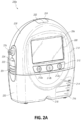
- FIG. 2A illustrates a front view 200A of a pump assembly 230 and canister 220 according to some embodiments.
- the pump assembly 230 comprises one or more indicators, such as visual indicator 202 configured to indicate alarms and visual indicator 204 configured to indicate status of the TNP system.
- the indicators 202 and 204 can be configured to alert a user to a variety of operating and/or failure conditions of the system, including alerting the user to normal or proper operating conditions, pump failure, power supplied to the pump or power failure, detection of a leak within the wound cover or flow pathway, suction blockage, or any other similar or suitable conditions or combinations thereof.
- the pump assembly 230 can comprise additional indicators.
- the indicator 202 can be configured to signal alarm conditions, such as canister full (or dressing full in case of a canisterless system), power low, conduit 140 disconnected, seal broken in the wound seal 120, and so on.
- the indicator 202 can be configured to display red flashing light to draw user's attention.
- the indicator 204 can be configured to signal status of the TNP system, such as therapy delivery is ok, leak detected, and so on.
- the indicator 204 can be configured to display one or more different colors of light, such as green, yellow, etc. For example, green light can be emitted when the TNP system is operating properly and yellow light can be emitted to indicate a warning.
- the pump assembly 230 comprises a display or screen 206 mounted in a recess 208 formed in a case of the pump assembly.
- the display 206 can be a touch screen display.
- the display 206 can support playback of audiovisual (AV) content, such as instructional videos.
- AV audiovisual
- the display 206 can be configured to render a number of screens or graphical user interfaces (GUIs) for configuring, controlling, and monitoring the operation of the TNP system.
- the pump assembly 230 comprises a gripping portion 210 formed in the case of the pump assembly.
- the gripping portion 210 can be configured to assist the user to hold the pump assembly 230, such as during removal of the canister 220.
- the canister 220 can be replaced with another canister, such as when the canister 220 has been filled with exudate.
- the canister 220 can include solidifier material.
- the pump assembly 230 comprises one or more keys or buttons 212 configured to allow the user to operate and monitor the operation of the TNP system. As is illustrated, in some embodiments, there buttons 212a, 212b, and 212c are included. Button 212a can be configured as a power button to turn on/off the pump assembly 230. Button 212b can be configured as a play/pause button for the delivery of negative pressure therapy. For example, pressing the button 212b can cause therapy to start, and pressing the button 212b afterward can cause therapy to pause or end. Button 212c can be configured to lock the display 206 and/or the buttons 212. For instance, button 212c can be pressed so that the user does not unintentionally alter the delivery of the therapy.
- Button 212c can be depressed to unlock the controls. In other embodiments, additional buttons can be used or one or more of the illustrated buttons 212a, 212b, or 212c can be omitted. In some embodiments, multiple key presses and/or sequences of key presses can be used to operate the pump assembly 230.
- the pump assembly 230 includes one or more latch recesses 222 formed in the cover. In the illustrated embodiment, two latch recesses 222 can be formed on the sides of the pump assembly 230. The latch recesses 222 can be configured to allow attachment and detachment of the canister 220 using one or more canister latches 221.
- the pump assembly 230 comprises an air outlet 224 for allowing air removed from the wound cavity 110 to escape. Air entering the pump assembly can be passed through one or more suitable filters, such as antibacterial filters. This can maintain reusability of the pump assembly.
- the pump assembly 230 includes one or more strap mounts 226 for connecting a carry strap to the pump assembly 230 or for attaching a cradle. In the illustrated embodiment, two strap mounts 226 can be formed on the sides of the pump assembly 230. In some embodiments, various of these features are omitted and/or various additional features are added to the pump assembly 230.
- the canister 220 is configured to hold fluid (e.g., exudate) removed from the wound cavity 110.
- the canister 220 includes one or more latches 221 for attaching the canister to the pump assembly 230.
- the canister 220 comprises two latches 221 on the sides of the canister.
- the exterior of the canister 220 can formed from frosted plastic so that the canister is substantially opaque and the contents of the canister and substantially hidden from plain view.
- the canister 220 comprises a gripping portion 214 formed in a case of the canister.
- the gripping portion 214 can be configured to allow the user to hold the pump assembly 220, such as during removal of the canister from the apparatus 230.
- the canister 220 includes a substantially transparent window 216, which can also include graduations of volume.
- the illustrated 300 mL canister 220 includes graduations of 50 mL, 100 mL, 150 mL, 200 mL, 250 mL, and 300 mL.
- Other embodiments of the canister can hold different volume of fluid and can include different graduation scale.
- the canister 220 comprises a tubing channel 218 for connecting to the conduit 140. In some embodiments, various of these features, such as the gripping portion 214, are omitted and/or various additional features are added to the canister 220.
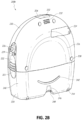
- FIG. 2B illustrates a rear view 200B of the pump assembly 230 and canister 220 according to some embodiments.
- the pump assembly 230 comprises a speaker port 232 for producing and/or radiating sound.
- the pump assembly 230 includes a filter access door 234 for accessing and replacing one or more filters, such as odor filter, antibacterial filters, etc.
- the access door 234 can be used to access a chamber (such as a plenum chamber) in which noise suppressing or sound absorbing material is placed.
- the chamber and sound absorbing material can be part of a silencing system that is used to suppress or absorb noise generated by the source of negative pressure. Sound absorbing material can serve to break up sound waves as travel (or reverberate) through the chamber.
- Sound absorbing material can further function as an odor suppressant.
- sound absorbing material can be impregnated with activated charcoal for odor suppression.
- the access door 234 can further include a seal (such as a sealing gasket) for tight closure of the chamber. Additional details of the silencing system are described in U.S. Patent Publication No. 2010/0185165 .
- the pump assembly 230 comprises a gripping portion 236 formed in the case of the pump assembly.
- the gripping portion 236 is a recess formed in the outer casing of the pump assembly 230.
- the gripping portion 236 may include rubber, silicone, etc. coating.
- the gripping portion 236 can be configured (e.g., positioned and dimensioned) to allow the user to firmly hold the pump assembly 230, such as during removal of the canister 220.
- the pump assembly 230 includes one or more covers 238 configured as screw covers and/or feet or protectors for placing the pump assembly 230 on a surface.
- the covers 230 can be formed out of rubber, silicone, or any other suitable material.
- the pump assembly 230 comprises a power jack 239 for charging and recharging an internal battery of the pump assembly.
- the power jack 239 is a direct current (DC) jack.
- the pump assembly can comprise a disposable power source, such as batteries, so that no power jack is needed.
- the canister 220 includes one or more feet 244 for placing the canister on a surface.
- the feet 244 can be formed out of rubber, silicone, or any other suitable material and can be angled at a suitable angle so that the canister 220 remains stable when placed on the surface.
- the canister 220 comprises a tube mount relief 246 configured to allow one or more tubes to exit to the front of the device.
- the canister 220 includes a stand or kickstand 248 for supporting the canister when it is placed on a surface. As explained below, the kickstand 248 can pivot between an opened and closed position. In closed position, the kickstand 248 can be latched to the canister 220. In some embodiments, the kickstand 248 can be made out of opaque material, such as plastic.
- the kickstand 248 can be made out of transparent material.
- the kickstand 248 includes a gripping portion 242 formed in the kickstand.
- the gripping portion 242 can be configured to allow the user to place the kickstand 248 in the closed position.
- the kickstand 248 comprises a hole 249 to allow the user to place the kickstand in the open position.
- the hole 249 can be sized to allow the user to extend the kickstand using a finger.
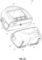
- FIG. 2C illustrates a view 200C of the pump assembly 230 separated from the canister 220 according to some embodiments.
- the pump assembly 230 includes a vacuum attachment or connector 252 through which a vacuum pump communicates negative pressure to the canister 220.
- the connector 252 can correspond to the inlet of the pump assembly.
- the pump assembly 230 comprises a USB access door 256 configured to allow access to one or more USB ports.
- the USB access door is omitted and USB ports are accessed through the door 234.
- the pump assembly 230 can include additional access doors configured to allow access to additional serial, parallel, and/or hybrid data transfer interfaces, such as SD, Compact Disc (CD), DVD, FireWire, Thunderbolt, PCI Express, and the like. In other embodiments, one or more of these additional ports are accessed through the door 234.
- FIG. 2D illustrates a view 200D of the interior components of the pump assembly 230 according to some embodiments.
- the pump assembly 230 can include various components, such as a canister connector 252 which includes a sealing ring 253, control printed circuit board (PCB) 260, peripherals PCB 262 (e.g., for USB connectivity), power supply PCB 264, vacuum pump 266, power supply 268 (e.g., rechargeable battery), speaker 270, and light guide or pipe 272 (e.g., for status indication using guided light emitted by one or more LEDs). Further details of status indication are provided in U.S. Patent No. 8,294,586 . Other components can be included, such as electrical cables, connectors, tubing, valves, filters, fasteners, screws, holders, and so on.
- the pump assembly 230 can comprise alternative or additional components.
- Figure 2E illustrates another view 200E of the interior components of the pump assembly 230 according to some embodiments.
- the pump assembly 230 includes an antenna 276.
- the connector 252 between the vacuum pump 266 and the canister 220 includes a flow restrictor 278.
- the flow restrictor 278 can be a calibrated flow restrictor used for measuring flow in the fluid flow path and for determining various operating conditions, such as leaks, blockages, high pressure (over-vacuum), and the like.
- flow across the restrictor 278 can be determined by measuring a pressure differential (or pressure drop) across the flow restrictor.
- flow across the restrictor 278 can be characterized as high flow (e.g., due to a leak), low flow (e.g., due to a blockage or canister being full), normal flow, etc.
- pressure sensor 284 measures pressure upstream (or on the canister side) of the flow restrictor 278.
- Pressure sensor 284 can be an electronic pressure sensor mounted on the control PCB 264.
- Conduit or lumen 286 can connect the upstream side of the flow restrictor 278 with the pressure sensor 284.
- Pressure sensors 280 and 282 measure pressure downstream (or on the vacuum pump side) of the flow restrictor 278.
- Pressure sensors 280 and 282 can be electronic pressure sensors mounted on the control PCB 264.
- Conduit or lumen 288 can connect the downstream side of the flow restrictor 278 with the pressure sensors 280 and 284 via a Y-connector 289.
- one of pressure sensors 280 and 282 can be designated as a primary pressure sensor and the other as a backup pressure sensor in case the primary pressure sensor becomes defective or inoperative.
- pressure sensor 280 can be the primary pressure sensor and pressure sensor 282 can be the backup pressure sensor.
- Pressure drop across the flow restrictor 278 can be determined by subtracting pressure measured by sensor 280 and sensor 284. If pressure sensor 280 fails, pressure drop across the flow restrictor can be determined by subtracting pressure measured by sensor 282 and sensor 284.
- the backup pressure sensor can be used for monitoring and indicating high pressure conditions, that is when the pressure in the flow path exceeds a maximum pressure threshold.
- one or more differential pressure sensors can be used.
- a differential pressure sensor connected to the upstream and downstream sides of the flow restrictor 278 can measure the pressure drop across the flow restrictor.
- these components such as the flow restrictor 278, are omitted and/or additional components, such as one or more flow meters, are used.
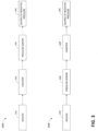
- Figure 3 illustrates a fluid flow path 300A according to some embodiments.
- the flow path 300A includes a wound cavity 310, canister 320, pressure sensor 330, and source of negative pressure 340.
- the flow of fluid is from left to right (e.g., from the wound 310 to the negative pressure source 340).
- Figure 3 illustrates a fluid flow path 300B according to some embodiments.
- the flow path 300B includes the wound 310 cavity, pressure sensor 330, canister 320, and source of negative pressure 340.
- the flow of fluid is from left to right (e.g., from the wound cavity 310 to the negative pressure source 340).
- the difference between flow paths 300A and 300B is the positioning of the pressure sensor 330.
- the pressure sensor 330 is located downstream of the canister 320 (e.g., at the inlet of the negative pressure source 340), while in the fluid flow path 300B the pressure sensor 330 is located upstream of the canister 320.
- Some embodiments of the system monitor and/or determine a rate of flow of fluid in the system.
- flow rate monitoring can be performed by a controller or processor. Monitoring the flow rate can be used, among other things, to ensure that therapy is properly delivered to the wound, to detect blockages, canister full (or dressing full in case of a canisterless system) conditions, and/or leaks in the fluid flow path, high pressure, ensure that the flow rate is not unsafe (e.g., dangerously high), etc.
- the system performs flow rate monitoring indirectly by measuring and/or monitoring activity of the negative pressure source.
- speed of vacuum pump motor can be measured, such as, by using a tachometer.
- a pump control processor can continuously monitor the pump speed using the tachometer feedback from the pump. If pump speed falls below a threshold value over a particular period of time, such as 2 minutes, it can be determined that a blockage is present in the flow path, particularly in systems in which an minimum pump speed is expected (e.g., due to a presence of a controlled leak).
- the blockage can be due to a blockage in a tube or lumen, canister (or dressing) being full, etc.
- activity of the negative pressure source can be measured by one or more other suitable techniques, such as by using a pump speed sensor (e.g., Hall sensor), measuring back EMF generated by the pump motor, and the like.
- a pump control processor can continuously monitor voltage and/or current at which the pump is being driven, and determine the activity of the negative pressure source based on the monitored voltage and/or current and load on the pump.
- pulse frequency e.g., pressure signal frequency
- a count of pressure pulses can be used as an indicator of the activity of the negative pressure source.
- tachometer can be read periodically, such as every 100 msec, and periodic readings made over a time duration, such as 2.5 seconds, 32 second, or any other suitable duration can be combined (e.g., averaged).
- Combined tachometer readings can be used for leak detection, blockage detection, limiting the maximum flow rate, etc.
- Combined tachometer readings (e.g., in counts) can be converted to a flow rate (e.g., in mL/min) using one or more conversion equations and/or tables so that a current flow rate is determined.
- the determined flow rate can be compared to various flow rate thresholds, such as blockage threshold, leakage threshold, and maximum flow rate threshold, to determine a presence of a particular condition, such as a blockage, leakage, and over-vacuum.
- the values for Slope and Intercept can be determined for possible pressure setpoints (e.g., -25 mmHg, -40 mmHg, -50 mmHg, 60 mmHg, -70 mmHg, -80 mmHg, -90 mmHg, -100 mmHg, -120 mmHg, -140 mmHg, 160 mmHg, -180 mmHg, -200 mmHg) for a given vacuum pump type.
- the flow as a function of the pump speed may not be a best fit as a single line because the vacuum pump can be designed to be more efficient at lower flow rates. Because of this, slope and intercept values can be pre-computed for various setpoints and various pumps. Flow rate can be measured in standard liters per minute (SLPM) or any other suitable measurement unit.
- a blockage condition is detected when the determined flow rate falls below a blockage threshold.
- a blockage alarm can be enabled if the blockage condition is present over a period of time, such as 30 seconds.
- the blockage alarm can be disabled when the determined flow rate exceeds the blockage threshold.
- the system can differentiate between a blockage in a tube or lumen and canister (or dressing) full conditions.
- a leakage condition is detected when the determined flow rate exceeds a leakage threshold.
- a leakage alarm can be enabled if the leakage condition is present over a period of time, such as 30 seconds.
- the leakage alarm can be disabled when the detected flow rate falls below the leakage threshold.
- a maximum flow rate is imposed, such as 1.6 liters/min.
- Pump drive signal such as voltage or current signal, can be limited not exceed the flow rate threshold.
- one or more pressure sensors can be placed in suitable locations in the fluid flow path. Pressure measured by the one or more sensors is provided to the system (e.g., pump control processor) so that it can determine and adjust the pump drive signal to achieve a desired negative pressure level.
- the pump drive signal can be generated using PWM. Additional details of flow rate detection and pump control are provided in U.S. Patent Application No. 2013/0150813 .
- flow rate monitoring is performed by measuring flow through a flow restrictor placed in a portion of the fluid flow path.
- flow restrictor 278 illustrated in Figure 2E can be used.
- the flow restrictor can be calibrated such that it can be used to reliably monitor flow rate for different types of wounds, dressings, and operating conditions.
- a high precision silicon flow restrictor can be used.
- the flow restrictor can be built using other suitable materials.
- the flow restrictor can be located at any suitable location in the flow path, such as between the source of the negative pressure and the canister, such as upstream of the source of the negative pressure and downstream of the canister.
- a differential pressure sensor or two pressure sensors can be used to measure a pressure drop across the flow restrictor.
- the pressure drop across the flow restrictor 278 can be measured using sensors 282 and 284.
- the measured flow rate is compared to a flow rate threshold. If the measured flow rate falls below the flow rate threshold, blockage condition is detected. Additional details of blockage detection are provided in U.S. Patent Publication No. 2011/0071483 .
- the measured flow rate is compared to a leakage threshold. If the measured flow rate exceeds the leakage threshold, a leak is detected. Additional details of leakage detection are provided in U.S. Patent No. 8,308,714 .
- blockages and presence of exudate in one or more tubes or lumens are detected by processing data from one or more pressure sensors, such as sensors 280, 282, and 284.
- This detection can be enhanced by changing one or more settings of the vacuum pump, such as increasing vacuum level delivered by the pump, decreasing the vacuum level, stopping the pump, changing the pump speed, changing a cadence of the pump, and the like.
- the pump as the pump operates, it generates pressure pulses or signals that are propagated through the fluid flow path. The pressure signals are illustrated in the pressure curve 402 of Figure 4 according to some embodiments.
- region 404 pressure in the fluid flow path varies or oscillates around a particular pressure setting or set point 408 (e.g., as selected by the user) during normal operation of the system.
- Region 406 illustrates pressure pulses in the flow path when there is a blockage distal to the negative pressure source, such as the canister (or dressing) becomes full and/or a canister filter is occluded or blocked.
- a distal blockage causes a reduced volume to be seen upstream of the canister (or dressing), and the amplitude of the pressure pulses increases.
- the frequency of a pressure signal is slowed or decreased in some embodiments.
- this change or "bounce" in the magnitude (or frequency) of the pressure pulse signal can be magnified or enhanced by varying the pump speed, varying the cadence of the pump, such as by adjusting PWM parameters, and the like. Such adjustments of pump operation are not required but can be performed over short time duration and the changes can be small such that the operation of the system remains relatively unaffected.
- the canister filter can be hydrophobic so that the flow of liquid is substantially blocked while the flow of air is allowed. Additional details of flow rate detection are described in U.S. Patent Publication No. 2012/0078539 .
- canisterless systems use absorbent dressing for exudate removed from the wound.
- Such dressing may include absorbing or superabsorbing material to collect and/or retain exudate so that it is not aspirated into the negative pressure source.
- a dressing filter (which may be hydrophobic) may be used to prevent the exudate from reaching the negative pressure source.
- detection of a dressing full condition or dressing filter (which may be) occluded condition can be an equivalent to detection of a canister full condition.
- changes in characteristics of pressure signals can be used to determine distal blockages, level of exudate in the canister (or dressing), canister (or dressing) full conditions, and the like.
- the characteristics can include signal magnitude, frequency, shape (e.g., envelope), etc.
- the system can detect canister (or dressing) pre-full condition or the level of exudate in the canister (or dressing) reaching a certain threshold, which may be less than being approximately 100% full. For example, the system can detect the canister (or dressing) being 75% full, 80% full, 95%, and so on.
- such detection mechanisms can provide earlier indication of the need to change the canister (or dressing) and avoid prolonged interruption of the delivery of therapy. Sensitivity of alarms can be increased.
- the level of a leak in present in the fluid flow path does not affect accurate determination of the level of exudate in the canister and/or detection of the canister (or dressing) pre-full or full conditions.
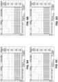
- Figures 5A-5D illustrates graphs of pressure signals according to some embodiments.
- the illustrated graphs can correspond to a particular pressure setting, such as 40 mmHg.
- the illustrated graphs can also correspond to various leak levels of leak rates in the system.
- Figure 5A may correspond to 60 mL/min leak (e.g., low leak)
- Figure 5B may correspond to a 150 mL/min leak
- Figure 5C may correspond to a 450 mL/min leak
- Figure 5D may correspond to a 1000 mL/min leak (e.g., very high leak).
- Figure 5A illustrates a magnitude curve 502A of the pressure signal in the flow path as sensed by one or more pressure sensors over a period of time.
- Curve 502A can correspond to a signal observed when the canister is relatively empty.
- the canister may be configured to hold up to 750 mL fluid volume, and curve 502A can correspond to the empty volume of 515 mL.
- the bounce in the pressure signal magnitude curve 502A is relatively small as the curve is substantially flat.
- the bounce of the pressure signal can be measured using a variety of techniques, such as by measuring peak-to-trough change and selecting the largest such change as being indicative of the largest bounce.
- Curve 502A can correspond to the voltage reading, current reading, etc.
- Curve 504A corresponds to a pump speed signal (e.g., as measured by a tachometer, PWM signal, etc.).
- Figure 5B illustrates a magnitude curve 502B of the pressure signal in the flow path as sensed by one or more pressure sensors over a period of time.
- Curve 502B can correspond to a signal observed when the canister is relatively full.
- the canister may be configured to hold up to 750 mL volume, and curve 502B can correspond to the empty volume of 60 mL.
- the bounce in the pressure signal magnitude curve 502B is larger than that in curve 502A.
- Curve 504B corresponds to the pump speed signal.
- Figure 5C illustrates a magnitude curve 502C of the pressure signal in the flow path as sensed by one or more pressure sensors over a period of time. Curve 502C can correspond to a signal observed when the canister is almost full.
- the canister may be configured to hold up to 750 mL volume, and curve 502C can correspond to the empty volume of 30 mL. As is illustrated, the bounce in the pressure signal magnitude curve 502B is larger than that in curves 502A and 502B. Curve 504C corresponds to the pump speed signal.
- Figure 5D illustrates a magnitude curve 502D of the pressure signal in the flow path as sensed by one or more pressure sensors over a period of time.
- Curve 502D can correspond to a signal observed when the canister is nearly full.
- the canister may be configured to hold up to 750 mL volume, and curve 502D can correspond to the empty volume of 15 mL.
- the bounce in the pressure signal magnitude curve 502D is larger than that in curves 502A, 502B, and 502C.
- Curve 504D corresponds to the pump speed signal.
- Table 1 illustrates the largest magnitude bounces or peak-to-trough changes (e.g., in voltage as indicated by V p-p ) measured for the curves 502A, 502B, 502C, and 502D according to some embodiments.
- column A corresponds to curve 502A and indicates the largest change of 0.010 V
- column B corresponds to curve 502D and indicates the largest change of 0.078 V
- column C corresponds to curve 502C and indicates the largest change of 0.122 V
- column D corresponds to curve 502D and indicates the largest change of 0.170 V.
- Level of exudate in the canister (or the dressing) can be detected by comparing the determined pressure magnitude bounce to one or more magnitude thresholds, which can be determined experimentally for canisters (or dressing) of various sizes.
- canister (or dressing) pre-full condition may be set to the canister having 30 mL or less empty volume.
- a pre-full threshold can be set to approximately 0.12 V peak-to-trough bounce.
- measures other than or in addition to peak-to-trough can be used, such as average bounce, etc.
- Table 1 Pressure Magnitude Bounce at 40 mmHg Pressure Magnitude (V p-p ) at 40 mmHg D C B A 15 mL volume 30 mL volume 60 mL volume 515 mL volume 1 60 mL/min 0.170 0.122 0.078 0.010 2 150 mL/min 0.174 0.120 0.074 0.012 3 450 mL/min 0.178 0.118 0.068 0.008 4 1000 mL/min 0.124 0.082 0.050 0.012
- signal processing techniques can be utilized on the detected pressure signal.
- sensed pressure values can be processed, such as lowpass filtered (e.g., via averaging), to remove noise.
- detected pressure signal can be converted into frequency domain, for example by using the Fast Fourier Transform (FFT). The signal can be processed and analyzed in frequency domain.
- FFT Fast Fourier Transform
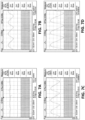
- Figures 6A-6D illustrates graphs of pressure signals according to some embodiments. Similar to Figures 5A-5D , these graphs illustrate pressure magnitude curves and pump speed curves at 150 mL/min leak for unfilled canister volumes of 515 mL, 60 mL, 30 mL, and 15 mL. As is illustrated in Figures 6A-6D and confirmed by the values in the second row (row 2) of Table 1, the bounce in the pressure signal increases as the canister fills up.
- Figures 7A-7D illustrates graphs of pressure signals according to some embodiments.
- FIGS 5A-5D illustrate pressure magnitude curves and pump speed curves at 450 mL/min leak for unfilled canister volumes of 515 mL, 60 mL, 30 mL, and 15 mL.
- Figures 8A-8D illustrates graphs of pressure signals according to some embodiments. Similar to Figures 5A-5D , these graphs illustrate pressure magnitude curves and pump speed curves at 1000 mL/min leak (which is a very high leak) for unfilled canister volumes of 515 mL, 60 mL, 30 mL, and 15 mL.
- Figure 9 illustrates sensed pressure magnitude ripple according to some embodiments.
- the y-axis represents largest peak-to-trough voltage changes.
- the x-axis corresponds to canister unfilled volumes (e.g., volume ahead or upstream of the pump).
- a 750 mL canister is used according to some embodiments.
- Table 2 illustrates the plotted values according to some embodiments.
- thresholds for determining the level of exudate in the canister (or the dressing) and/or canister (or dressing) pre-full condition can be determined for various pressure settings and various canister volumes.
- Table 3 illustrates the largest magnitude bounces or peak-to-trough changes for 80 mmHg pressure setting according to some embodiments. Similar tables can be constructed for other possible pressure settings.
- Level of exudate in the canister/dressing (and, accordingly, a measure of how empty the canister/dressing is), canister/dressing pre-full condition, and/or canister/dressing full condition can be determined at run time by loading a table corresponding to a particular selected pressure setting and comparing the monitored pressure signal magnitude bounce to one or more thresholds.
- Table 3 Pressure Magnitude Bounce at 80 mmHg Pressure Magnitude (V p-p ) at 80 mmHg D C B A 15 mL volume 30 mL volume 60 mL volume 515 mL volume 1 60 mL/min 0.114 0.078 0.048 0.008 2 150 mL/min 0.116 0.084 0.050 0.008 3 450 mL/min 0.128 0.080 0.050 0.008 4 1000 mL/min 0.092 0.058 0.034 0.010
- frequency of the detected pressure signal can be used in addition to or instead of changes in amplitude for detection of canister (or dressing) pre-full conditions and/or for determining the level of exudate in the canister (or dressing).
- Table 4 illustrates pressure signal frequencies at 40 mmHg pressure setting for various unfilled canister volumes at various leak rates according to some embodiments. As is shown in Table 4, the frequency of the detected pressure signal decreases or drops as the canister becomes full (e.g., compare column A corresponding to 515 mL unfilled canister volume to column D corresponding to 15 mL unfilled canister volume). This change in the frequency is observed irrespective of the leak rate.
- the frequency of the detected pressure signal can be compared to one or more frequency thresholds, which may be determined experimentally, to detect canister (or dressing) pre-full condition and/or detect the level of exudate in the canister (or dressing).
- Table 4 Pressure Signal Frequency at 40 mmHg Pressure Frequency at 40 mmHg (Hz) D C B A 15 mL volume 30 mL volume 60 mL volume 515 mL volume 1 60 mL/min 2.59 2.67 2.67 2.62 2 150 mL/min 3.51 3.76 3.75 3.53 3 450 mL/min 6.62 6.94 6.99 6.94 4 1000 mL/min 13.16 12.99 12.66 13.89
- Similar tables can be constructed for other possible pressure settings.
- Table 5 illustrates pressure signal frequencies at 80 mmHg pressure setting for various unfilled canister volumes at various leak rates according to some embodiments.
- Level of exudate in the canister (or dressing), canister (or dressing) pre-full condition, and/or canister (or dressing) full condition can be determined at run time by loading a table (or another suitable data structure) corresponding to a particular selected pressure setting and comparing the monitored pressure signal frequency to one or more thresholds.
- the thresholds can be determined experimentally for various canister (or dressing) volumes.
- additional attributes can be used for canister (or dressing) pre-full detection and/or determination of the level of exudate in the canister (or dressing).
- flow rate through the flow path can be used in addition to analyzing the pressure magnitude.
- flow rate can be measured indirectly by measuring and analyzing the pump speed as is disclosed in U.S. Patent Publication No. 2012/0001762 .
- flow rate can be measured directly by using a flow meter.
- increase in the pressure magnitude bounce and decrease in the flow rate indicates a canister (or dressing) full condition.
- Decrease in the pump speed alone may not be a reliable indicator of the canister full condition as such decrease can be caused by an improved seal and resulting lowering of the leak rate.
- presence of a small leak in the flow path may cause the pump to continue working even though the canister may be nearly full or full, which can cause inaccurate detection of the canister full condition.
- detection of canister (or dressing) pre-full and/or full conditions using the characteristics of the pressure signals can allow the system to differentiate between blockage conditions in the fluid flow path and blockages in the canister (or in the dressing).
- alarm sensitivity is improved.
- canister full detection mechanisms in systems that do not use characteristics of the pressure signal may rely solely on the flow rate measurements (e.g., as indicated by pump speed measurements) for determining whether the canister is full.
- Using characteristics of the pressure signal as disclosed herein can trigger the canister full alarm much earlier, such as for example 20 or more minutes earlier.
- improving alarm sensitivity can result in increasing safety and patient comfort as the canister can be changed timely before it becomes full and therapy is interrupted.
- Figure 10 illustrates a process 1000 of detecting proximal blockages according to some embodiments.
- the process 1000 can be implemented by a controller of processor.
- the process 1000 measures one or more pressure signal characteristics in block 1002. For example, pressure signal magnitude, frequency, etc. can be measured.
- the process 1000 removes noise from the one or more measured pressure signal characteristics. For example, the pressure signal can be low pass filtered.
- the process 1000 compares the one or more pressure signal characteristics to one or more thresholds. If in block 1008 the process 1000 determines that the one or more thresholds have been satisfied (e.g., exceeded), the process transitions to block 1012 where it determines that there is a proximal blockage (e.g., due to the canister being full).
- the process 1000 can activate one or more alarms or indicators. If in block 1008 the process 1000 determines that the one or more thresholds have not been satisfied (e.g., not exceeded), the process transitions to block 1010 where it determines that there is no proximal blockage. In some embodiments, the process 1000 can use hysteresis in block 1008. For example, the process 1000 can transition to block 1012 provided that a threshold has been met (e.g., exceeded) for a duration or period of time. In some embodiments, the one or more thresholds utilized by the process 1000 can be selected to determine canister (or dressing) pre-full condition and/or a particular level of exudate in the canister (or dressing). Process 1000 can be implemented by systems with canisters or by canisterless systems.
- canister (or dressing) full condition can be detected as follows.
- the values can be voltage values, current values, or any other suitable values that correspond to pressure.
- a difference between maximum and minimum values for a particular sample period corresponds to peak-to-through pressure (which is indicative of change in pressure pulse amplitude). If it is determined that the peak-to-through pressure for a particular sample period exceeds a threshold pressure value, then the particular sample period indicates that the canister is full.
- the threshold is a value selected or determined based on the negative pressure setpoint and the current level of activity of the pump, which as explained above can be determined using a tachometer average (such as averaged tachometer readings or any other suitable measure of the flow rate).
- a tachometer average such as averaged tachometer readings or any other suitable measure of the flow rate.
- threshold values listed in Table 1 can be used for comparing to peak-to-through pressure. These values correspond to a particular pump motor and particular pressure sensor.
- Threshold values for detecting canister full condition Tachometer Frequency (in Hz) Peak-to-Through Pressure (in mV) Setpoint (in mmHg) Low Med High Low Med High 25 17 25 ⁇ 25 50 110 215 40 23 35 ⁇ 35 75 135 220 50 30 50 ⁇ 50 90 175 225 60 30 55 ⁇ 55 80 185 225 70 40 60 ⁇ 60 115 185 235 80 40 60 ⁇ 60 100 165 235 90 45 65 ⁇ 65 110 170 235 100 45 65 ⁇ 65 105 165 235 120 45 75 ⁇ 75 105 175 235 140 50 85 ⁇ 85 110 190 235 160 60 90 ⁇ 90 110 165 220 180 75 100 ⁇ 100 130 165 220 200 75 100 ⁇ 100 125 155 210
- Canister full determination can be performed on a sliding window basis. For example, a sliding window of 25 out of 30 sample periods can be analyzed and if 25 sample periods are determined to indicate that the canister is full, the pump concludes that the canister (or dressing) is full. Assuming that the sample period is 2 seconds, using a sliding window of 25 out of 30 sample periods effectively results in determining whether change in pressure pulse amplitude exceeds the threshold for 60 seconds.
- canister full detection can be suspended or terminated. For example, if a sliding window of 25 out of 30 sample periods with each sample period having duration of 2 seconds in used, 60 second timer for canister full detection can be reset when it has been determined that the tachometer average becomes greater than the leak threshold or canister pressure becomes less than the low vacuum pressure threshold. This can prevent generation of unnecessary and undesirable alarms.
- a leak threshold e.g., flow rate associated with presence of a leak in the flow path
- canister pressure as measured by a pressure sensor
- a low vacuum pressure threshold e.g., flow rate associated with a low vacuum condition in the flow path
- canister full condition can be detected if a single sample period indicates that the canister is full.
- performing canister full detection using a plurality of sample periods can mitigate the effects of one or more transient conditions in the fluid flow path or one or more errant pressure readings.
- canister full detection can be performed by measuring the frequency of detected pressure signal and comparing the measured frequency to one or more suitable thresholds.
- additional or alternative mechanisms can be used for detecting proximal blockages.
- One or more additional pressure sensors can be used to measure differential pressure across the canister (e.g., at the canister inlet and outlet).
- One or more additional conduits e.g., dual lumens
- Flow rate can be measured directly or indirectly and used for canister blockage detection.
- a bias leak can be introduced into the flow path and maintained such that flow rate dropping below the bias leak rate indicates a presence of a blockage in the flow path.
- Optical sensors, ultrasonic sensors, and/or weight sensors can be used to determine the level of exudate in the canister (or dressing). Lasers can also be used.
- One or more sensors that are not related to measuring pressure and/or flow such as a capacitive sensor or a strain gauge, can be used.
- temporary blockages caused by slugs or boluses of fluid in tubes and/or lumens are detected by turning off the pump and monitoring the pressure change in the fluid flow path.
- the pump can be turned off for a short duration of time as to not affect the operation of the system.
- Presence of temporary blockages in the system due to boluses of fluid can cause a detectable difference in pressure decay in the device including a discontinuous "stair and risers" pattern in a system with a distal leak.
- Such discontinuous decaying pattern may be due to boluses of fluid moving through the fluid flow path and arriving at the canister inlet, which can suddenly change the volume seen by the pressure sensor (and the canister or the dressing).
- a more continuous decaying pattern may be is observed.
- the system can increase the level of vacuum produced by the pump to clear the boluses. An alarm can be asserted if the tubes and/or lumens cannot be cleared.
- one or more flow sensors and/or flow meters can be used to directly measure the fluid flow.
- the system can utilize one or more of the foregoing flow rate monitoring techniques.
- the system can be configured to suitably arbitrate between flow rates determined using multiple flow rate monitoring techniques if one or more such techniques are executed in parallel.
- the system execute one of the techniques, such as the flow rate determination based on the pump speed, and utilize one or more other techniques as needed.
- the system can utilize one or more other techniques in cases the determined flow rate or flow path condition is perceived to be inaccurate or unreliable.
- the system can utilize one or more of the techniques to detect a sudden change in a flow rate suggesting change to the dressing leak characteristics (e.g., a greater flow indicates the development of a leak and a lesser flow indicating a sudden restriction or blockage).
- any value of a magnitude, frequency, threshold, limit, duration, etc. provided herein and/or illustrated in the figures is not intended to be absolute and, thereby, can be approximate.
- any magnitude, frequency, threshold, limit, duration, etc. provided herein and/or illustrated in the figures can be fixed or varied either automatically or by a user.
- any value of a magnitude, frequency, threshold, limit, duration, etc. provided herein and/or illustrated in the figures is illustrative and can change depending on an embodiment.
- the values provided in the tables (Tables 1-5) can vary depending on canister (or dressing) volume, sensor range, etc.
- relative terminology such as exceeds, greater than, less than, etc.
- the various components illustrated in the figures may be implemented as software and/or firmware on a processor, controller, ASIC, FPGA, and/or dedicated hardware.
- the features and attributes of the specific embodiments disclosed above may be combined in different ways to form additional embodiments, all of which fall within the scope of the present disclosure.
- User interface screens illustrated and described herein can include additional and/or alternative components. These components can include menus, lists, buttons, text boxes, labels, radio buttons, scroll bars, sliders, checkboxes, combo boxes, status bars, dialog boxes, windows, and the like. User interface screens can include additional and/or alternative information. Components can be arranged, grouped, displayed in any suitable order.
Description
- This application claims the benefit of
U.S. Provisional Application No. 61/865,516, filed on August 13, 2013 - Embodiments of the present disclosure relate to methods (not claimed) and apparatuses for dressing and treating a wound with reduced pressure therapy or topical negative pressure (TNP) therapy. In particular, but without limitation, embodiments disclosed herein relate to negative pressure therapy devices, methods for controlling the operation of TNP systems, and methods of using TNP systems.
- Embodiments of the present disclosure relate to methods (not claimed) and apparatuses for dressing and treating a wound with reduced pressure therapy or topical negative pressure (TNP) therapy. In particular, but without limitation, embodiments disclosed herein relate to negative pressure therapy devices, methods for controlling the operation of TNP systems, and method of using TNP systems. Relevant prior art can be found in
US 2012/078539 A1 ,WO 2008/036360 A2 ,GB 2 342 584 A WO 03/101508 A2 US 2007/032763 A1 andWO 2016/018448 A1 . In addition, embodiments disclosed herein relate to attachment mechanisms or systems for negative pressure therapy devices. - The invention is defined in the appended claims.
- In some (not claimed) embodiments, a negative pressure wound therapy apparatus includes a negative pressure source configured to be in fluid communication with a wound dressing, the negative pressure source configured to provide negative pressure to the wound, a canister configured to be in fluid communication with the dressing and the negative pressure source, the canister configured to collect exudate removed from the wound, and a pressure sensor configured to monitor one or more characteristics of pressure signals generated by the negative pressure source. The apparatus also includes a controller configured to determine a level of exudate in the canister based at least in part on the measured one or more characteristics of the pressure signals.
- The apparatus of the preceding paragraph may also include any combination of the following features described in this paragraph, among others described herein. The measured one or more characteristics of the pressure signals can include magnitude of the pressure signals, and the magnitude of the pressure signals can increase as the level of exudate in the canister increases. The canister can include a filter configured to become occluded in order to prevent overflow of the canister and the controller can be further configured to detect a canister pre-full condition before the filter becomes occluded. The controller can also provide an indication of the canister pre-full condition to a user. The controller can be configured to determine the level of exudate in the canister based at least in part on the measured one or more characteristics of the pressure signals and a measured activity level of the negative pressure source. The negative pressure source can include a vacuum pump and the activity level of the negative pressure source corresponds to a speed of the vacuum pump. The apparatus can include a tachometer configured to measure the speed of the vacuum pump.
- The apparatus of any of the preceding paragraphs may also include any combination of the following features described in this paragraph, among others described herein. The apparatus can include a fluid flow path configured to fluidically connect the dressing, the canister, and the negative pressure source, and the controller can be further configured to determine a leak rate of fluid in the flow path based at least in part on the activity level of the negative pressure source and determine the level of exudate in the canister based at least in part on the measured one or more characteristics of the pressure signals and the determined leak rate. The controller can be configured to remove noise from the measured one or more characteristics of the pressure signals. The controller can be configured to determine the level of exudate in the canister based at least in part on comparing the measured one or more characteristics of the pressure signals to one or more thresholds. The measured one or more characteristics can include magnitude and frequency of pressure pulses and the controller can be configured to determine the level of exudate in the canister based at least in part on the magnitude and frequency of the pressure signals. The magnitude of the pressure signals can increase as the level of exudate in the canister increases and the frequency of the pressure signals can decrease as the level of exudate in the canister increases.
- The apparatus of any of the preceding paragraphs may also include any combination of the following features described in this paragraph, among others described herein. The controller can be configured to determine the level of exudate in the canister irrespective of an intensity of a leak present in a fluid flow path configured to fluidically connect the dressing, the canister, and the negative pressure source. The controller can be configured to determine the level of exudate in the canister based at least in part on a change in the measured one or more characteristics of the pressure signals. The apparatus can include a wound dressing configured to be placed over a wound.
- In certain (not claimed) embodiments, a method of operating a negative pressure wound therapy apparatus includes monitoring pressure signals generated by a negative pressure source in fluid communication with a wound dressing and a canister and determining a level of aspirated exudate in the canister based at least in part on one or more characteristics of the monitored pressure signals.
- The method of the preceding paragraph may also include any combination of the following features described in this paragraph, among others described herein. One or more characteristics of the monitored pressure signals can include magnitude of the pressure signals, and the magnitude of the pressure signals can increase as the level of exudate in the canister increases. The canister can include a filter configured to become occluded in order to prevent overflow of the canister and the method can further include detecting a canister pre-full condition before the filter becomes occluded. An indication of the canister pre-full condition can be provided to a user. The method can include measuring activity level of the negative pressure source and determining the level of exudate in the canister based at least in part on the one or more characteristics of the monitored pressure signals and the measured activity level. The negative pressure source can include a vacuum pump and the activity level of the negative pressure source corresponds to a speed of the vacuum pump. A tachometer can used to measure the speed of the vacuum pump. The method can include determining a leak rate of fluid in a flow path based at least in part on the activity level of the negative pressure source and determining the level of exudate in the canister based at least in part on the one or more characteristics of the monitored pressure signals and the determined leak rate. The fluid flow path can fluidically connect a dressing placed over a wound, the negative pressure source, and the canister.
- The method of any of the preceding paragraphs may also include any combination of the following features described in this paragraph, among others described herein. The method can include removing noise from the pressure signal measurements. The method can include determining the level of exudate in the canister based at least in part on comparing the one or more characteristics of the monitored pressure signals to one or more thresholds. The one or more characteristics of the monitored pressure signals can include magnitude and frequency of the pressure signals and the method can further include determining the level of exudate in the canister based at least in part on the magnitude and the frequency of the monitored pressure signals. The magnitude of the pressure signals can increase as the level of exudate in the canister increases and the frequency of the pressure signals can decrease as the level of exudate in the canister increases. Determining the level of aspirated exudate in the canister is performed irrespective of an intensity of a leak present in a fluid flow fluidically connecting the dressing, the canister, and the negative pressure source. The method can include determining the level of exudate in the canister based at least in part on a change in the one or more characteristics of the monitored pressure signals.
- In various (not claimed) embodiments, a negative pressure wound therapy apparatus includes a dressing configured to be placed over a wound, the dressing configured to collect exudate removed from the wound, a negative pressure source configured to be in fluid communication with the dressing, the negative pressure source configured to provide negative pressure to the wound, and a pressure sensor configured to monitor one or more characteristics of pressure signals generated by the negative pressure source. The apparatus also includes a controller configured to determine a level of exudate in the dressing based at least in part on the monitored one or more characteristics of the pressure signals.
- The apparatus of any of the preceding paragraphs may also include any combination of the following features described in this paragraph, among others described herein. The monitored one or more characteristics of the pressure signals can include magnitude of the pressure signals, and the magnitude of the pressure signals can increase as the level of exudate in the dressing increases. The dressing can include a filter configured to become occluded in order to prevent overflow and the controller can be further configured to detect a dressing pre-full condition before the filter becomes occluded and provide an indication of the dressing pre-full condition to a user. The controller can be further configured to determine the level of exudate in the dressing based at least in part on the monitored one or more characteristics of the pressure signals and a measured activity level of the negative pressure source. The apparatus can further include a fluid flow path configured to fludicially connect the dressing and the negative pressure source and the controller can be further configured to determine a leak rate of fluid in the flow path based at least in part on the activity level of the negative pressure source and to determine the level of exudate in the dressing based at least in part on the monitored one or more characteristics of the pressure signals and the determined leak rate.
- The apparatus of any of the preceding paragraphs may also include any combination of the following features described in this paragraph, among others described herein. The controller can be configured to determine the level of exudate in the dressing based at least in part on comparing the monitored one or more characteristics of the pressure signals to one or more thresholds The monitored one or more characteristics of the pressure signals can include magnitude and frequency of the pressure signals and the controller can be further configured to determine the level of exudate in the dressing based at least in part on the magnitude and the frequency of the pressure signals. The magnitude of the pressure signals can increase as the level of exudate in the dressing increases and the frequency of the pressure signals can decrease as the level of exudate in the dressing increases. The controller can be configured to determine the level of exudate in the dressing irrespective of an intensity of a leak present in a fluid flow path configured to fluidically connect the dressing and negative pressure source. The controller can be configured to determine the level of exudate in the dressing based at least in part on a change in the monitored one or more characteristics of the pressure signals.
- In some (not claimed) embodiments, a method of operating a negative wound therapy apparatus includes monitoring pressure signals generated by a negative pressure source in fluid communication with a wound dressing and a canister and determining a level of aspirated exudate in the dressing based at least in part on one or more characteristics of the monitored pressure signals.
- The method of any of the preceding paragraphs may also include any combination of the following features described in this paragraph, among others described herein. The monitored one or more characteristics of the pressure signals include magnitude of the pressure signals, and wherein the magnitude of the pressure signals increases as the level of exudate in the dressing increases. The dressing can include a filter configured to become occluded in order to prevent overflow and the method can further include detecting a dressing pre-full condition before the filter becomes occluded and providing an indication of the dressing pre-full condition to a use. The method can further include measuring activity level of the negative pressure source and determining the level of exudate in the dressing based at least in part on the monitored one or more characteristics of the pressure signals and the measured activity level.
- The method of any of the preceding paragraphs may also include any combination of the following features described in this paragraph, among others described herein. The method can include determining a leak rate of fluid in the flow path based at least in part on the activity level of the negative pressure source, the fluid flow path fludicially connecting the dressing and the negative pressure source and determining the level of exudate in the dressing based at least in part on the monitored one or more characteristics of the pressure signals and the determined leak rate. The method can include determining the level of exudate in the dressing based at least in part on comparing the monitored one or more characteristics of the pressure signals to one or more thresholds. The monitored one or more characteristics of the pressure signals can include magnitude and frequency of the pressure signals and the method can further include determining the level of exudate in the dressing based at least in part on the magnitude and the frequency of the pressure signals. The magnitude of the pressure signals can increase as the level of exudate in the dressing increases and the frequency of the pressure signals can decrease as the level of exudate in the dressing increases. The method can further include determining the level of exudate in the dressing irrespective of an intensity of a leak present in a fluid flow path fluidically connecting the dressing and negative pressure source.
- Embodiments of the present invention will now be described hereinafter, by way of example only, with reference to the accompanying drawings in which:
-
Figure 1 illustrates a reduced pressure wound therapy system according to some embodiments. -
Figures 2A-2E illustrate a pump assembly and canister according to some embodiments. -
Figure 3 illustrates fluid flow paths according to some embodiments. -
Figure 4 illustrates a graph of pressure signals according to some embodiments. -
Figures 5A-5D illustrate graphs of pressure signals according to some embodiments. -
Figures 6A-6D illustrate graphs of pressure signals according to some embodiments. -
Figures 7A-7D illustrate graphs of pressure signals according to some embodiments. -
Figures 8A-8D illustrate graphs of pressure signals according to some embodiments. -
Figure 9 illustrates sensed pressure magnitude ripple according to some embodiments. -
Figure 10 illustrates a process of detecting proximal blockages according to some embodiments. - Embodiments disclosed herein relate to systems and methods of treating a wound with reduced pressure. As is used herein, reduced or negative pressure levels, such as -X mmHg, represent pressure levels relative to normal ambient atmospheric pressure, which can correspond to 760 mmHg (or 1 atm, 29.93 inHg, 101.325 kPa, 14.696 psi, etc.). Accordingly, a negative pressure value of -X mmHg reflects absolute pressure that is X mmHg below 760 mmHg or, in other words, an absolute pressure of (760-X) mmHg. In addition, negative pressure that is "less" or "smaller" than X mmHg corresponds to pressure that is closer to atmospheric pressure (e.g., -40 mmHg is less than -60 mmHg). Negative pressure that is "more" or "greater" than X mmHg corresponds to pressure that is further from atmospheric pressure (e.g., -80 mmHg is more than -60 mmHg). In some embodiments, local ambient atmospheric pressure is used as a reference point, and such local atmospheric pressure may not necessarily be, for example, 760 mmHg.
- Embodiments of the present invention are generally applicable to use in topical negative pressure ("TNP") or reduced pressure therapy systems. Briefly, negative pressure wound therapy assists in the closure and healing of many forms of "hard to heal" wounds by reducing tissue oedema, encouraging blood flow and granular tissue formation, and/or removing excess exudate and can reduce bacterial load (and thus infection risk). In addition, the therapy allows for less disturbance of a wound leading to more rapid healing. TNP therapy systems can also assist in the healing of surgically closed wounds by removing fluid. In some embodiments, TNP therapy helps to stabilize the tissue in the apposed position of closure. A further beneficial use of TNP therapy can be found in grafts and flaps where removal of excess fluid is important and close proximity of the graft to tissue is required in order to ensure tissue viability.
- In some embodiments, a negative pressure wound therapy apparatus includes a dressing configured to be placed over a wound and a source of negative pressure configured to be in fluid communication with the dressing. The source of negative pressure is configured to provide negative pressure to the wound. The apparatus can also include a canister configured to collect exudate removed from the wound. The canister can be configured to be in fluid communication with the dressing and the negative pressure source. The apparatus also includes a pressure sensor configured to monitor pressure signals generated by the negative pressure source and a controller. The controller can be configured to determine a level of exudate in the canister (or in the dressing) based at least in part on one or more characteristics of the monitored pressure signals. The one or more characteristics of the pressure signals can change as a level of exudate in the canister increases.
- In various embodiments, a method of operating a negative pressure wound therapy apparatus includes monitoring pressure signals generated by a negative pressure source in fluid communication with a dressing and a canister. The method also includes determining a level of exudate in the canister (or in the dressing) based at least in part on one or more characteristics of the monitored pressure signals. The one or more characteristics of the pressure signals can change as a level of exudate in the canister increases.
- In some embodiments, systems and methods for determining an amount of flow restriction or reduced volume in front of a negative pressure utilize one or more characteristics of monitored pressure signals. For example, the magnitude of the pressure signals can increase as restriction to flow increase, which effectively reduces the volume in front of a negative pressure source. The volume in front of the negative pressure source may decrease due to filling of a canister or dressing with exudate removed from a wound.
-
Figure 1 illustrates an embodiment of a negative or reduced pressure wound treatment (or TNP)system 100 comprising awound filler 130 placed inside awound cavity 110, the wound cavity sealed by awound cover 120. Thewound filler 130 in combination with thewound cover 120 can be referred to as wound dressing. A single or multi lumen tube orconduit 140 is connected thewound cover 120 with apump assembly 150 configured to supply reduced pressure. Thewound cover 120 is in fluidic communication with thewound cavity 110. In any of the system embodiments disclosed herein, as in the embodiment illustrated inFigure 1 , the pump assembly can be a canisterless (not claimed) pump assembly (meaning that exudate is collected in the wound dressing is transferred viatube 140 for collection to another location). However, any of the pump assembly embodiments disclosed herein can be configured to include (as claimed) or support a canister. Additionally, in any of the system embodiments disclosed herein, any of the pump assembly embodiments can be mounted to or supported by the dressing, or adjacent to the dressing. Thewound filler 130 can be any suitable type, such as hydrophilic or hydrophobic foam, gauze, inflatable bag, and so on. Thewound filler 130 can be conformable to thewound cavity 110 such that it substantially fills the cavity at atmospheric pressure, and also may have a substantially reduced compressed volume when under negative pressure. Thewound cover 120 can provide a substantially fluid impermeable seal over thewound cavity 110. In some embodiments, thewound cover 120 has a top side and a bottom side, and the bottom side adhesively (or in any other suitable manner) seals withwound cavity 110. Theconduit 140 or any other conduit disclosed herein can be formed from polyurethane, PVC, nylon, polyethylene, silicone, or any other suitable material. - Some embodiments of the
wound cover 120 can have a port (not shown) configured to receive an end of theconduit 140. In some embodiments, theconduit 140 can otherwise pass through and/or under thewound cover 120 to supply reduced pressure to thewound cavity 110 so as to maintain a desired level of reduced pressure in the wound cavity. Theconduit 140 can be any suitable article configured to provide at least a substantially sealed fluid flow pathway between thepump assembly 150 and thewound cover 120, so as to supply the reduced pressure provided by thepump assembly 150 to woundcavity 110. - The
wound cover 120 and thewound filler 130 can be provided as a single article or an integrated single unit. In some embodiments, no wound filler is provided and the wound cover by itself may be considered the wound dressing. The wound dressing may then be connected, via theconduit 140, to a source of negative pressure, such as thepump assembly 150. In some embodiments, though not required, thepump assembly 150 can be miniaturized and portable, although larger conventional pumps such can also be used. - The
wound cover 120 can be located over a wound site to be treated. Thewound cover 120 can form a substantially sealed cavity or enclosure over the wound site. In some embodiments, thewound cover 120 can be configured to have a film having a high water vapour permeability to enable the evaporation of surplus fluid, and can have a superabsorbing material contained therein to safely absorb wound exudate. It will be appreciated that throughout this specification reference is made to a wound. In this sense it is to be understood that the term wound is to be broadly construed and encompasses open and closed wounds in which skin is torn, cut or punctured or where trauma causes a contusion, or any other surficial or other conditions or imperfections on the skin of a patient or otherwise that benefit from reduced pressure treatment. A wound is thus broadly defined as any damaged region of tissue where fluid may or may not be produced. Examples of such wounds include, but are not limited to, acute wounds, chronic wounds, surgical incisions and other incisions, subacute and dehisced wounds, traumatic wounds, flaps and skin grafts, lacerations, abrasions, contusions, burns, diabetic ulcers, pressure ulcers, stoma, surgical wounds, trauma and venous ulcers or the like. In some embodiments, the components of the TNP system described herein can be particularly suited for incisional wounds that exude a small amount of wound exudate. - Some embodiments of the system (not claimed) are designed to operate without the use of an exudate canister. Some embodiments can be configured to support an exudate canister. In some embodiments, configuring the
pump assembly 150 andtubing 140 so that thetubing 140 can be quickly and easily removed from thepump assembly 150 can facilitate or improve the process of dressing or pump changes, if necessary. Any of the pump embodiments disclosed herein can be configured to have any suitable connection between the tubing and the pump. - In some embodiments, the
pump assembly 150 can be configured to deliver negative pressure at a desired negative pressure setpoint, which can be selected or programmed to be approximately -80 mmHg, or between about -20 mmHg and -200 mmHg (e.g., as selected by a user). Note that these pressures are relative to normal ambient atmospheric pressure thus, -200 mmHg would be about 560 mmHg in practical terms. In some embodiments, the pressure range can be between about -40 mmHg and -150 mmHg. Alternatively a pressure range of up to -75 mmHg, up to -80 mmHg or over -80 mmHg can be used. Also in other embodiments a pressure range of below -75 mmHg can be used. Alternatively a pressure range of over approximately -100 mmHg, or even 150 mmHg, can be supplied by thepump assembly 150. - In some embodiments, the
pump assembly 150 is configured to provide continuous or intermittent negative pressure therapy. Continuous therapy can be delivered at above -25 mmHg, -25 mmHg, -40 mmHg, -50 mmHg, -60 mmHg, -70 mmHg, -80 mmHg, - 90 mmHg, -100 mmHg, -120 mmHg, -140 mmHg, -160 mmHg, -180 mmHg, -200 mmHg, or below -200 mmHg. Intermittent therapy can be delivered between low and high negative pressure set points. Low set point can be set at above 0 mmHg, 0 mmHg, -25 mmHg, -40 mmHg, -50 mmHg, -60 mmHg, -70 mmHg, -80 mmHg, -90 mmHg, -100 mmHg, -120 mmHg, -140 mmHg, -160 mmHg, -180 mmHg, or below -180 mmHg. High set point can be set at above -25 mmHg, -40 mmHg, -50 mmHg, -60 mmHg, -70 mmHg, -80 mmHg, -90 mmHg, -100 mmHg, -120 mmHg, -140 mmHg, -160 mmHg, -180 mmHg, -200 mmHg, or below -200 mmHg. During intermittent therapy, negative pressure at low set point can be delivered for a first time duration, and upon expiration of the first time duration, negative pressure at high set point can be delivered for a second time duration. Upon expiration of the second time duration, negative pressure at low set point can be delivered. The first and second time durations can be same or different values. The first and second durations can be selected from the following range: less than 2 minutes, 2 minutes, 3 minutes, 4 minutes, 6 minutes, 8 minutes, 10 minutes, or greater than 10 minutes. In some embodiments, switching between low and high set points and vice versa can be performed according to a step waveform, square waveform, sinusoidal waveform, and the like. - In operation, the
wound filler 130 is inserted into thewound cavity 110 and woundcover 120 is placed so as to seal thewound cavity 110. Thepump assembly 150 provides a source of a negative pressure to thewound cover 120, which is transmitted to thewound cavity 110 via thewound filler 130. Fluid (e.g., wound exudate) is drawn through theconduit 140, and can be stored in a canister. In some embodiments, fluid is absorbed by thewound filler 130 or one or more absorbent layers (not shown). - Wound dressings that may be utilized with the pump assembly and other embodiments of the present application include Renasys-F, Renasys-G, Renasys AB, and Pico Dressings available from Smith & Nephew. Further description of such wound dressings and other components of a negative pressure wound therapy system that may be used with the pump assembly and other embodiments of the present application are found in
U.S. Patent Publication Nos. 2012/0116334 ,2011/0213287 ,2011/0282309 ,2012/0136325 ,2013/0110058 . In other embodiments, other suitable wound dressings can be utilized. -
Figure 2A illustrates a front view 200A of apump assembly 230 andcanister 220 according to some embodiments. As is illustrated, thepump assembly 230 and the canister are connected, thereby forming a device. Thepump assembly 230 comprises one or more indicators, such asvisual indicator 202 configured to indicate alarms andvisual indicator 204 configured to indicate status of the TNP system. Theindicators pump assembly 230 can comprise additional indicators. In some embodiments, a single indicator is used. In other embodiments, multiple indicators are used. Any suitable indicator can be used such as visual, audio, tactile indicator, and so on. Theindicator 202 can be configured to signal alarm conditions, such as canister full (or dressing full in case of a canisterless system), power low,conduit 140 disconnected, seal broken in thewound seal 120, and so on. Theindicator 202 can be configured to display red flashing light to draw user's attention. Theindicator 204 can be configured to signal status of the TNP system, such as therapy delivery is ok, leak detected, and so on. Theindicator 204 can be configured to display one or more different colors of light, such as green, yellow, etc. For example, green light can be emitted when the TNP system is operating properly and yellow light can be emitted to indicate a warning. - The
pump assembly 230 comprises a display orscreen 206 mounted in arecess 208 formed in a case of the pump assembly. In some embodiments, thedisplay 206 can be a touch screen display. In some embodiments, thedisplay 206 can support playback of audiovisual (AV) content, such as instructional videos. As explained below, thedisplay 206 can be configured to render a number of screens or graphical user interfaces (GUIs) for configuring, controlling, and monitoring the operation of the TNP system. Thepump assembly 230 comprises agripping portion 210 formed in the case of the pump assembly. The grippingportion 210 can be configured to assist the user to hold thepump assembly 230, such as during removal of thecanister 220. In some embodiments, thecanister 220 can be replaced with another canister, such as when thecanister 220 has been filled with exudate. Thecanister 220 can include solidifier material. - The
pump assembly 230 comprises one or more keys orbuttons 212 configured to allow the user to operate and monitor the operation of the TNP system. As is illustrated, in some embodiments, therebuttons Button 212a can be configured as a power button to turn on/off thepump assembly 230. Button 212b can be configured as a play/pause button for the delivery of negative pressure therapy. For example, pressing the button 212b can cause therapy to start, and pressing the button 212b afterward can cause therapy to pause or end.Button 212c can be configured to lock thedisplay 206 and/or thebuttons 212. For instance,button 212c can be pressed so that the user does not unintentionally alter the delivery of the therapy.Button 212c can be depressed to unlock the controls. In other embodiments, additional buttons can be used or one or more of the illustratedbuttons pump assembly 230. - The
pump assembly 230 includes one or more latch recesses 222 formed in the cover. In the illustrated embodiment, twolatch recesses 222 can be formed on the sides of thepump assembly 230. The latch recesses 222 can be configured to allow attachment and detachment of thecanister 220 using one or more canister latches 221. Thepump assembly 230 comprises anair outlet 224 for allowing air removed from thewound cavity 110 to escape. Air entering the pump assembly can be passed through one or more suitable filters, such as antibacterial filters. This can maintain reusability of the pump assembly. Thepump assembly 230 includes one or more strap mounts 226 for connecting a carry strap to thepump assembly 230 or for attaching a cradle. In the illustrated embodiment, two strap mounts 226 can be formed on the sides of thepump assembly 230. In some embodiments, various of these features are omitted and/or various additional features are added to thepump assembly 230. - The
canister 220 is configured to hold fluid (e.g., exudate) removed from thewound cavity 110. Thecanister 220 includes one ormore latches 221 for attaching the canister to thepump assembly 230. In the illustrated embodiment, thecanister 220 comprises twolatches 221 on the sides of the canister. The exterior of thecanister 220 can formed from frosted plastic so that the canister is substantially opaque and the contents of the canister and substantially hidden from plain view. Thecanister 220 comprises agripping portion 214 formed in a case of the canister. The grippingportion 214 can be configured to allow the user to hold thepump assembly 220, such as during removal of the canister from theapparatus 230. Thecanister 220 includes a substantiallytransparent window 216, which can also include graduations of volume. For example, the illustrated 300mL canister 220 includes graduations of 50 mL, 100 mL, 150 mL, 200 mL, 250 mL, and 300 mL. Other embodiments of the canister can hold different volume of fluid and can include different graduation scale. Thecanister 220 comprises atubing channel 218 for connecting to theconduit 140. In some embodiments, various of these features, such as the grippingportion 214, are omitted and/or various additional features are added to thecanister 220. -
Figure 2B illustrates a rear view 200B of thepump assembly 230 andcanister 220 according to some embodiments. Thepump assembly 230 comprises aspeaker port 232 for producing and/or radiating sound. Thepump assembly 230 includes afilter access door 234 for accessing and replacing one or more filters, such as odor filter, antibacterial filters, etc. In one embodiment, theaccess door 234 can be used to access a chamber (such as a plenum chamber) in which noise suppressing or sound absorbing material is placed. The chamber and sound absorbing material can be part of a silencing system that is used to suppress or absorb noise generated by the source of negative pressure. Sound absorbing material can serve to break up sound waves as travel (or reverberate) through the chamber. Sound absorbing material can further function as an odor suppressant. In one embodiment, for example, sound absorbing material can be impregnated with activated charcoal for odor suppression. Theaccess door 234 can further include a seal (such as a sealing gasket) for tight closure of the chamber. Additional details of the silencing system are described inU.S. Patent Publication No. 2010/0185165 . - The
pump assembly 230 comprises agripping portion 236 formed in the case of the pump assembly. As is illustrated, the grippingportion 236 is a recess formed in the outer casing of thepump assembly 230. In some embodiments, the grippingportion 236 may include rubber, silicone, etc. coating. The grippingportion 236 can be configured (e.g., positioned and dimensioned) to allow the user to firmly hold thepump assembly 230, such as during removal of thecanister 220. Thepump assembly 230 includes one ormore covers 238 configured as screw covers and/or feet or protectors for placing thepump assembly 230 on a surface. Thecovers 230 can be formed out of rubber, silicone, or any other suitable material. Thepump assembly 230 comprises apower jack 239 for charging and recharging an internal battery of the pump assembly. In some embodiments, thepower jack 239 is a direct current (DC) jack. In some embodiments, the pump assembly can comprise a disposable power source, such as batteries, so that no power jack is needed. - The
canister 220 includes one ormore feet 244 for placing the canister on a surface. Thefeet 244 can be formed out of rubber, silicone, or any other suitable material and can be angled at a suitable angle so that thecanister 220 remains stable when placed on the surface. Thecanister 220 comprises atube mount relief 246 configured to allow one or more tubes to exit to the front of the device. Thecanister 220 includes a stand orkickstand 248 for supporting the canister when it is placed on a surface. As explained below, thekickstand 248 can pivot between an opened and closed position. In closed position, thekickstand 248 can be latched to thecanister 220. In some embodiments, thekickstand 248 can be made out of opaque material, such as plastic. In other embodiments, thekickstand 248 can be made out of transparent material. Thekickstand 248 includes agripping portion 242 formed in the kickstand. The grippingportion 242 can be configured to allow the user to place thekickstand 248 in the closed position. Thekickstand 248 comprises ahole 249 to allow the user to place the kickstand in the open position. Thehole 249 can be sized to allow the user to extend the kickstand using a finger. -
Figure 2C illustrates a view 200C of thepump assembly 230 separated from thecanister 220 according to some embodiments. Thepump assembly 230 includes a vacuum attachment orconnector 252 through which a vacuum pump communicates negative pressure to thecanister 220. Theconnector 252 can correspond to the inlet of the pump assembly. Thepump assembly 230 comprises aUSB access door 256 configured to allow access to one or more USB ports. In some embodiments, the USB access door is omitted and USB ports are accessed through thedoor 234. Thepump assembly 230 can include additional access doors configured to allow access to additional serial, parallel, and/or hybrid data transfer interfaces, such as SD, Compact Disc (CD), DVD, FireWire, Thunderbolt, PCI Express, and the like. In other embodiments, one or more of these additional ports are accessed through thedoor 234. -
Figure 2D illustrates a view 200D of the interior components of thepump assembly 230 according to some embodiments. Thepump assembly 230 can include various components, such as acanister connector 252 which includes asealing ring 253, control printed circuit board (PCB) 260, peripherals PCB 262 (e.g., for USB connectivity),power supply PCB 264,vacuum pump 266, power supply 268 (e.g., rechargeable battery),speaker 270, and light guide or pipe 272 (e.g., for status indication using guided light emitted by one or more LEDs). Further details of status indication are provided inU.S. Patent No. 8,294,586 . Other components can be included, such as electrical cables, connectors, tubing, valves, filters, fasteners, screws, holders, and so on. In some embodiments, thepump assembly 230 can comprise alternative or additional components. -
Figure 2E illustrates another view 200E of the interior components of thepump assembly 230 according to some embodiments. As is explained below, thepump assembly 230 includes anantenna 276. Theconnector 252 between thevacuum pump 266 and thecanister 220 includes aflow restrictor 278. As is explained below, theflow restrictor 278 can be a calibrated flow restrictor used for measuring flow in the fluid flow path and for determining various operating conditions, such as leaks, blockages, high pressure (over-vacuum), and the like. In some embodiments, flow across therestrictor 278 can be determined by measuring a pressure differential (or pressure drop) across the flow restrictor. In various embodiments, flow across therestrictor 278 can be characterized as high flow (e.g., due to a leak), low flow (e.g., due to a blockage or canister being full), normal flow, etc. As is illustrated,pressure sensor 284 measures pressure upstream (or on the canister side) of theflow restrictor 278.Pressure sensor 284 can be an electronic pressure sensor mounted on thecontrol PCB 264. Conduit orlumen 286 can connect the upstream side of theflow restrictor 278 with thepressure sensor 284.Pressure sensors flow restrictor 278.Pressure sensors control PCB 264. Conduit orlumen 288 can connect the downstream side of theflow restrictor 278 with thepressure sensors connector 289. - In some embodiments, one of
pressure sensors pressure sensor 280 can be the primary pressure sensor andpressure sensor 282 can be the backup pressure sensor. Pressure drop across theflow restrictor 278 can be determined by subtracting pressure measured bysensor 280 andsensor 284. Ifpressure sensor 280 fails, pressure drop across the flow restrictor can be determined by subtracting pressure measured bysensor 282 andsensor 284. In certain embodiments, the backup pressure sensor can be used for monitoring and indicating high pressure conditions, that is when the pressure in the flow path exceeds a maximum pressure threshold. In some embodiments, one or more differential pressure sensors can be used. For example, a differential pressure sensor connected to the upstream and downstream sides of theflow restrictor 278 can measure the pressure drop across the flow restrictor. In some embodiments, one or more of these components, such as theflow restrictor 278, are omitted and/or additional components, such as one or more flow meters, are used. -
Figure 3 illustrates afluid flow path 300A according to some embodiments. Theflow path 300A includes awound cavity 310,canister 320,pressure sensor 330, and source ofnegative pressure 340. The flow of fluid is from left to right (e.g., from thewound 310 to the negative pressure source 340).Figure 3 illustrates afluid flow path 300B according to some embodiments. Theflow path 300B includes thewound 310 cavity,pressure sensor 330,canister 320, and source ofnegative pressure 340. The flow of fluid is from left to right (e.g., from thewound cavity 310 to the negative pressure source 340). As is illustrated, the difference betweenflow paths pressure sensor 330. Influid flow path 300A thepressure sensor 330 is located downstream of the canister 320 (e.g., at the inlet of the negative pressure source 340), while in thefluid flow path 300B thepressure sensor 330 is located upstream of thecanister 320. - Some embodiments of the system monitor and/or determine a rate of flow of fluid in the system. In certain embodiments, flow rate monitoring can be performed by a controller or processor. Monitoring the flow rate can be used, among other things, to ensure that therapy is properly delivered to the wound, to detect blockages, canister full (or dressing full in case of a canisterless system) conditions, and/or leaks in the fluid flow path, high pressure, ensure that the flow rate is not unsafe (e.g., dangerously high), etc.
- In some embodiments, the system performs flow rate monitoring indirectly by measuring and/or monitoring activity of the negative pressure source. For example, speed of vacuum pump motor can be measured, such as, by using a tachometer. A pump control processor can continuously monitor the pump speed using the tachometer feedback from the pump. If pump speed falls below a threshold value over a particular period of time, such as 2 minutes, it can be determined that a blockage is present in the flow path, particularly in systems in which an minimum pump speed is expected (e.g., due to a presence of a controlled leak). The blockage can be due to a blockage in a tube or lumen, canister (or dressing) being full, etc. An alarm can be triggered and the system can wait for the user to take one or more actions to resolve the blockage. In some embodiments, activity of the negative pressure source can be measured by one or more other suitable techniques, such as by using a pump speed sensor (e.g., Hall sensor), measuring back EMF generated by the pump motor, and the like. A pump control processor can continuously monitor voltage and/or current at which the pump is being driven, and determine the activity of the negative pressure source based on the monitored voltage and/or current and load on the pump. In some embodiments, pulse frequency (e.g., pressure signal frequency) can be monitored (e.g., using one or more pressure sensors) to determine the activity of the negative pressure source. For example, a count of pressure pulses can be used as an indicator of the activity of the negative pressure source.
- In various embodiments, tachometer can be read periodically, such as every 100 msec, and periodic readings made over a time duration, such as 2.5 seconds, 32 second, or any other suitable duration can be combined (e.g., averaged). Combined tachometer readings can be used for leak detection, blockage detection, limiting the maximum flow rate, etc. Combined tachometer readings (e.g., in counts) can be converted to a flow rate (e.g., in mL/min) using one or more conversion equations and/or tables so that a current flow rate is determined. In some embodiments, the flow rate is determined according to the following equation:

where FR is the flow rate, F is the frequency of the pump tachometer signal, P is pressure produced by the pump (or pressure setpoint), and C1 and C2 are suitable constants. The determined flow rate can be compared to various flow rate thresholds, such as blockage threshold, leakage threshold, and maximum flow rate threshold, to determine a presence of a particular condition, such as a blockage, leakage, and over-vacuum. - Other suitable ways for determining flow rate can be used. For example, the flow rate can be periodically computed, such as every 250 milliseconds or any other suitable time value, according to the following formula:

where Tachometer is an average of tachometer readings (e.g., in Hz), such as over last 2.5 second or any other suitable period of time, and Slope and Intercept are constants that are based on the pressure setpoint. The values for Slope and Intercept can be determined for possible pressure setpoints (e.g., -25 mmHg, -40 mmHg, -50 mmHg, 60 mmHg, -70 mmHg, -80 mmHg, -90 mmHg, -100 mmHg, -120 mmHg, -140 mmHg, 160 mmHg, -180 mmHg, -200 mmHg) for a given vacuum pump type. The flow as a function of the pump speed may not be a best fit as a single line because the vacuum pump can be designed to be more efficient at lower flow rates. Because of this, slope and intercept values can be pre-computed for various setpoints and various pumps. Flow rate can be measured in standard liters per minute (SLPM) or any other suitable measurement unit. - In some embodiments, a blockage condition is detected when the determined flow rate falls below a blockage threshold. A blockage alarm can be enabled if the blockage condition is present over a period of time, such as 30 seconds. The blockage alarm can be disabled when the determined flow rate exceeds the blockage threshold. In some embodiments, the system can differentiate between a blockage in a tube or lumen and canister (or dressing) full conditions. In some embodiments, a leakage condition is detected when the determined flow rate exceeds a leakage threshold. A leakage alarm can be enabled if the leakage condition is present over a period of time, such as 30 seconds. The leakage alarm can be disabled when the detected flow rate falls below the leakage threshold. In some embodiments, in order to prevent an over-vacuum condition, a maximum flow rate is imposed, such as 1.6 liters/min. Pump drive signal, such as voltage or current signal, can be limited not exceed the flow rate threshold.
- In certain embodiments, one or more pressure sensors can be placed in suitable locations in the fluid flow path. Pressure measured by the one or more sensors is provided to the system (e.g., pump control processor) so that it can determine and adjust the pump drive signal to achieve a desired negative pressure level. The pump drive signal can be generated using PWM. Additional details of flow rate detection and pump control are provided in
U.S. Patent Application No. 2013/0150813 . - In some embodiments, flow rate monitoring is performed by measuring flow through a flow restrictor placed in a portion of the fluid flow path. In certain embodiments,
flow restrictor 278 illustrated inFigure 2E can be used. The flow restrictor can be calibrated such that it can be used to reliably monitor flow rate for different types of wounds, dressings, and operating conditions. For example, a high precision silicon flow restrictor can be used. As another example, the flow restrictor can be built using other suitable materials. The flow restrictor can be located at any suitable location in the flow path, such as between the source of the negative pressure and the canister, such as upstream of the source of the negative pressure and downstream of the canister. A differential pressure sensor or two pressure sensors can be used to measure a pressure drop across the flow restrictor. For example, as explained above in connection withFigure 2E , the pressure drop across theflow restrictor 278 can be measured usingsensors U.S. Patent Publication No. 2011/0071483 . In some embodiments, the measured flow rate is compared to a leakage threshold. If the measured flow rate exceeds the leakage threshold, a leak is detected. Additional details of leakage detection are provided inU.S. Patent No. 8,308,714 . - In some embodiments, blockages and presence of exudate in one or more tubes or lumens are detected by processing data from one or more pressure sensors, such as
sensors pressure curve 402 ofFigure 4 according to some embodiments. As is illustrated inregion 404, pressure in the fluid flow path varies or oscillates around a particular pressure setting or set point 408 (e.g., as selected by the user) during normal operation of the system.Region 406 illustrates pressure pulses in the flow path when there is a blockage distal to the negative pressure source, such as the canister (or dressing) becomes full and/or a canister filter is occluded or blocked. As is illustrated, a distal blockage causes a reduced volume to be seen upstream of the canister (or dressing), and the amplitude of the pressure pulses increases. The frequency of a pressure signal is slowed or decreased in some embodiments. In certain embodiments, this change or "bounce" in the magnitude (or frequency) of the pressure pulse signal can be magnified or enhanced by varying the pump speed, varying the cadence of the pump, such as by adjusting PWM parameters, and the like. Such adjustments of pump operation are not required but can be performed over short time duration and the changes can be small such that the operation of the system remains relatively unaffected. In some embodiments, the canister filter can be hydrophobic so that the flow of liquid is substantially blocked while the flow of air is allowed. Additional details of flow rate detection are described inU.S. Patent Publication No. 2012/0078539 . - In some embodiments, canisterless systems use absorbent dressing for exudate removed from the wound. Such dressing may include absorbing or superabsorbing material to collect and/or retain exudate so that it is not aspirated into the negative pressure source. Similar to a canister filter, a dressing filter (which may be hydrophobic) may be used to prevent the exudate from reaching the negative pressure source. In such systems, detection of a dressing full condition or dressing filter (which may be) occluded condition can be an equivalent to detection of a canister full condition.
- In some embodiments, changes in characteristics of pressure signals can be used to determine distal blockages, level of exudate in the canister (or dressing), canister (or dressing) full conditions, and the like. The characteristics can include signal magnitude, frequency, shape (e.g., envelope), etc. In some embodiments, the system can detect canister (or dressing) pre-full condition or the level of exudate in the canister (or dressing) reaching a certain threshold, which may be less than being approximately 100% full. For example, the system can detect the canister (or dressing) being 75% full, 80% full, 95%, and so on. Advantageously, such detection mechanisms can provide earlier indication of the need to change the canister (or dressing) and avoid prolonged interruption of the delivery of therapy. Sensitivity of alarms can be increased. In various embodiments, the level of a leak in present in the fluid flow path does not affect accurate determination of the level of exudate in the canister and/or detection of the canister (or dressing) pre-full or full conditions.
-
Figures 5A-5D illustrates graphs of pressure signals according to some embodiments. The illustrated graphs can correspond to a particular pressure setting, such as 40 mmHg. The illustrated graphs can also correspond to various leak levels of leak rates in the system. For example,Figure 5A may correspond to 60 mL/min leak (e.g., low leak),Figure 5B may correspond to a 150 mL/min leak,Figure 5C may correspond to a 450 mL/min leak, andFigure 5D may correspond to a 1000 mL/min leak (e.g., very high leak).Figure 5A illustrates a magnitude curve 502A of the pressure signal in the flow path as sensed by one or more pressure sensors over a period of time. Curve 502A can correspond to a signal observed when the canister is relatively empty. For example, the canister may be configured to hold up to 750 mL fluid volume, and curve 502A can correspond to the empty volume of 515 mL. As is illustrated, the bounce in the pressure signal magnitude curve 502A is relatively small as the curve is substantially flat. The bounce of the pressure signal can be measured using a variety of techniques, such as by measuring peak-to-trough change and selecting the largest such change as being indicative of the largest bounce. Curve 502A can correspond to the voltage reading, current reading, etc. Curve 504A corresponds to a pump speed signal (e.g., as measured by a tachometer, PWM signal, etc.). -
Figure 5B illustrates a magnitude curve 502B of the pressure signal in the flow path as sensed by one or more pressure sensors over a period of time. Curve 502B can correspond to a signal observed when the canister is relatively full. For example, the canister may be configured to hold up to 750 mL volume, and curve 502B can correspond to the empty volume of 60 mL. As is illustrated, the bounce in the pressure signal magnitude curve 502B is larger than that in curve 502A. Curve 504B corresponds to the pump speed signal.Figure 5C illustrates a magnitude curve 502C of the pressure signal in the flow path as sensed by one or more pressure sensors over a period of time. Curve 502C can correspond to a signal observed when the canister is almost full. For example, the canister may be configured to hold up to 750 mL volume, and curve 502C can correspond to the empty volume of 30 mL. As is illustrated, the bounce in the pressure signal magnitude curve 502B is larger than that in curves 502A and 502B. Curve 504C corresponds to the pump speed signal. -
Figure 5D illustrates a magnitude curve 502D of the pressure signal in the flow path as sensed by one or more pressure sensors over a period of time. Curve 502D can correspond to a signal observed when the canister is nearly full. For example, the canister may be configured to hold up to 750 mL volume, and curve 502D can correspond to the empty volume of 15 mL. As is illustrated, the bounce in the pressure signal magnitude curve 502D is larger than that in curves 502A, 502B, and 502C. Curve 504D corresponds to the pump speed signal. - Table 1 illustrates the largest magnitude bounces or peak-to-trough changes (e.g., in voltage as indicated by Vp-p) measured for the curves 502A, 502B, 502C, and 502D according to some embodiments. With reference to the first row (row 1), column A corresponds to curve 502A and indicates the largest change of 0.010 V, column B corresponds to curve 502D and indicates the largest change of 0.078 V, column C corresponds to curve 502C and indicates the largest change of 0.122 V, and column D corresponds to curve 502D and indicates the largest change of 0.170 V. These increasing bounce values confirm that the bounce in the pressure signal magnitude increases as the canister fills up. Level of exudate in the canister (or the dressing) can be detected by comparing the determined pressure magnitude bounce to one or more magnitude thresholds, which can be determined experimentally for canisters (or dressing) of various sizes. For example, canister (or dressing) pre-full condition may be set to the canister having 30 mL or less empty volume. Using Table 1, a pre-full threshold can be set to approximately 0.12 V peak-to-trough bounce. In some embodiments, measures other than or in addition to peak-to-trough can be used, such as average bounce, etc.
Table 1: Pressure Magnitude Bounce at 40 mmHg Pressure Magnitude (Vp-p) at 40 mmHg D C B A 15 mL volume 30 mL volume 60 mL volume 515 mL volume 1 60 mL/min 0.170 0.122 0.078 0.010 2 150 mL/min 0.174 0.120 0.074 0.012 3 450 mL/min 0.178 0.118 0.068 0.008 4 1000 mL/min 0.124 0.082 0.050 0.012 - In some embodiments, signal processing techniques can be utilized on the detected pressure signal. For example, sensed pressure values can be processed, such as lowpass filtered (e.g., via averaging), to remove noise. As another example, detected pressure signal can be converted into frequency domain, for example by using the Fast Fourier Transform (FFT). The signal can be processed and analyzed in frequency domain.
-
Figures 6A-6D illustrates graphs of pressure signals according to some embodiments. Similar toFigures 5A-5D , these graphs illustrate pressure magnitude curves and pump speed curves at 150 mL/min leak for unfilled canister volumes of 515 mL, 60 mL, 30 mL, and 15 mL. As is illustrated inFigures 6A-6D and confirmed by the values in the second row (row 2) of Table 1, the bounce in the pressure signal increases as the canister fills up.Figures 7A-7D illustrates graphs of pressure signals according to some embodiments. Similar toFigures 5A-5D , these graphs illustrate pressure magnitude curves and pump speed curves at 450 mL/min leak for unfilled canister volumes of 515 mL, 60 mL, 30 mL, and 15 mL. As is illustrated inFigures 7A-7D and confirmed by the values in the third row (row 3) of Table 1, the bounce in the pressure signal increases as the canister fills up.Figures 8A-8D illustrates graphs of pressure signals according to some embodiments. Similar toFigures 5A-5D , these graphs illustrate pressure magnitude curves and pump speed curves at 1000 mL/min leak (which is a very high leak) for unfilled canister volumes of 515 mL, 60 mL, 30 mL, and 15 mL. As is illustrated inFigures 8A-8D and confirmed by the values in the fourth row (row 4) of Table 1, the bounce in the pressure signal increases as the canister fills up. From the illustrations inFigures 5-8 and the values in Table 1, it can be seen that detection of the level of exudate in the canister (or in the dressing) and/or canister (or dressing) pre-full condition can be performed irrespective of the leak rate in the fluid flow path. - As is illustrated in
Figures 5-8 and Table 1, the bounce or ripple in the observed pressure magnitude increases as the canister fills up and the volume "seen" by the pump decreases.Figure 9 illustrates sensed pressure magnitude ripple according to some embodiments. The y-axis represents largest peak-to-trough voltage changes. The x-axis corresponds to canister unfilled volumes (e.g., volume ahead or upstream of the pump). A 750 mL canister is used according to some embodiments. There are four curves illustrated corresponding to target pressure settings of 40 mmHg, 80 mmHg, 120 mmHg, and 200 mmHg. Vertical bars on the curves represent variation resulting from the changes to the leak rate. Table 2 illustrates the plotted values according to some embodiments. As is illustrated inFigure 9 and Table 2, magnitude of the pressure bounce increases as the canister becomes full irrespective of the leak rate for various pressure settings.Table 2 (∗ 1000 mL/min data was excluded) Vp-p * 15 mL volume 30 mL volume 60 mL volume 515 mL volume 40 mmHg 0.174 ± 0.008 0.120 ± 0.004 0.073 ± 0.010 0.010 ± 0.004 80 mmHg 0.119 ± 0.015 0.081 ± 0.006 0.049 ± 0.002 0.008 ± 0.000 120 mmHg 0.095 ± 0.005 0.061 ± 0.005 0.037 ± 0.002 0.006 ± 0.000 200 mmHg 0.056 ± 0.000 0.037 ± 0.009 0.027 ± 0.009 0.008 ± 0.000 - In some embodiments, thresholds for determining the level of exudate in the canister (or the dressing) and/or canister (or dressing) pre-full condition can be determined for various pressure settings and various canister volumes. For example, Table 3 illustrates the largest magnitude bounces or peak-to-trough changes for 80 mmHg pressure setting according to some embodiments. Similar tables can be constructed for other possible pressure settings. Level of exudate in the canister/dressing (and, accordingly, a measure of how empty the canister/dressing is), canister/dressing pre-full condition, and/or canister/dressing full condition can be determined at run time by loading a table corresponding to a particular selected pressure setting and comparing the monitored pressure signal magnitude bounce to one or more thresholds. Other suitable data structures can be used in place of a table, such as array, list, index, graph, etc.
Table 3: Pressure Magnitude Bounce at 80 mmHg Pressure Magnitude (Vp-p) at 80 mmHg D C B A 15 mL volume 30 mL volume 60 mL volume 515 mL volume 1 60 mL/min 0.114 0.078 0.048 0.008 2 150 mL/min 0.116 0.084 0.050 0.008 3 450 mL/min 0.128 0.080 0.050 0.008 4 1000 mL/min 0.092 0.058 0.034 0.010 - In some embodiments, frequency of the detected pressure signal can be used in addition to or instead of changes in amplitude for detection of canister (or dressing) pre-full conditions and/or for determining the level of exudate in the canister (or dressing). For example, Table 4 illustrates pressure signal frequencies at 40 mmHg pressure setting for various unfilled canister volumes at various leak rates according to some embodiments. As is shown in Table 4, the frequency of the detected pressure signal decreases or drops as the canister becomes full (e.g., compare column A corresponding to 515 mL unfilled canister volume to column D corresponding to 15 mL unfilled canister volume). This change in the frequency is observed irrespective of the leak rate. The frequency of the detected pressure signal can be compared to one or more frequency thresholds, which may be determined experimentally, to detect canister (or dressing) pre-full condition and/or detect the level of exudate in the canister (or dressing).
Table 4: Pressure Signal Frequency at 40 mmHg Pressure Frequency at 40 mmHg (Hz) D C B A 15 mL volume 30 mL volume 60 mL volume 515 mL volume 1 60 mL/min 2.59 2.67 2.67 2.62 2 150 mL/min 3.51 3.76 3.75 3.53 3 450 mL/min 6.62 6.94 6.99 6.94 4 1000 mL/min 13.16 12.99 12.66 13.89 - In some embodiments, similar tables can be constructed for other possible pressure settings. For example, Table 5 illustrates pressure signal frequencies at 80 mmHg pressure setting for various unfilled canister volumes at various leak rates according to some embodiments. Level of exudate in the canister (or dressing), canister (or dressing) pre-full condition, and/or canister (or dressing) full condition can be determined at run time by loading a table (or another suitable data structure) corresponding to a particular selected pressure setting and comparing the monitored pressure signal frequency to one or more thresholds. The thresholds can be determined experimentally for various canister (or dressing) volumes.
Table 5: Pressure Signal Frequency at 80 mmHg Pressure Frequency at 80 mmHg (Hz) D C B A 15 mL volume 30 mL volume 60 mL volume 515 mL volume 1 60 mL/min 3.76 3.83 3.82 3.82 2 150 mL/min 4.98 4.67 4.81 4.88 3 450 mL/min 8.26 8.47 8.26 8.20 4 1000 mL/min 15.38 15.63 15.15 15.87 - In some embodiments, additional attributes can be used for canister (or dressing) pre-full detection and/or determination of the level of exudate in the canister (or dressing). For example, flow rate through the flow path can be used in addition to analyzing the pressure magnitude. In some embodiments, flow rate can be measured indirectly by measuring and analyzing the pump speed as is disclosed in
U.S. Patent Publication No. 2012/0001762 . In some embodiments, flow rate can be measured directly by using a flow meter. In some embodiments, increase in the pressure magnitude bounce and decrease in the flow rate (e.g., pump speed, such as reflected by a slowing tachometer) indicates a canister (or dressing) full condition. Decrease in the pump speed alone may not be a reliable indicator of the canister full condition as such decrease can be caused by an improved seal and resulting lowering of the leak rate. In addition, presence of a small leak in the flow path may cause the pump to continue working even though the canister may be nearly full or full, which can cause inaccurate detection of the canister full condition. - In some embodiments, detection of canister (or dressing) pre-full and/or full conditions using the characteristics of the pressure signals can allow the system to differentiate between blockage conditions in the fluid flow path and blockages in the canister (or in the dressing). In some embodiments, alarm sensitivity is improved. For example, canister full detection mechanisms in systems that do not use characteristics of the pressure signal may rely solely on the flow rate measurements (e.g., as indicated by pump speed measurements) for determining whether the canister is full. Using characteristics of the pressure signal as disclosed herein can trigger the canister full alarm much earlier, such as for example 20 or more minutes earlier. Advantageously, improving alarm sensitivity can result in increasing safety and patient comfort as the canister can be changed timely before it becomes full and therapy is interrupted.
-
Figure 10 illustrates aprocess 1000 of detecting proximal blockages according to some embodiments. Theprocess 1000 can be implemented by a controller of processor. Theprocess 1000 measures one or more pressure signal characteristics inblock 1002. For example, pressure signal magnitude, frequency, etc. can be measured. Inblock 1004, theprocess 1000 removes noise from the one or more measured pressure signal characteristics. For example, the pressure signal can be low pass filtered. Inblock 1006, theprocess 1000 compares the one or more pressure signal characteristics to one or more thresholds. If inblock 1008 theprocess 1000 determines that the one or more thresholds have been satisfied (e.g., exceeded), the process transitions to block 1012 where it determines that there is a proximal blockage (e.g., due to the canister being full). Theprocess 1000 can activate one or more alarms or indicators. If inblock 1008 theprocess 1000 determines that the one or more thresholds have not been satisfied (e.g., not exceeded), the process transitions to block 1010 where it determines that there is no proximal blockage. In some embodiments, theprocess 1000 can use hysteresis inblock 1008. For example, theprocess 1000 can transition to block 1012 provided that a threshold has been met (e.g., exceeded) for a duration or period of time. In some embodiments, the one or more thresholds utilized by theprocess 1000 can be selected to determine canister (or dressing) pre-full condition and/or a particular level of exudate in the canister (or dressing).Process 1000 can be implemented by systems with canisters or by canisterless systems. - In some embodiments, canister (or dressing) full condition can be detected as follows. A plurality of pressure sensor readings, each performed over a time duration (e.g., 2 seconds or any other suitable duration which may be vary between sample periods), are collected. A number of readings of the plurality of readings, such as 25 sample periods out of 30 or any other suitable number, are checked to determine if each indicates that the canister is full. This can performed by determining maximum and minimum pressure values captured over the time duration of a particular sample period. The values can be voltage values, current values, or any other suitable values that correspond to pressure. A difference between maximum and minimum values for a particular sample period corresponds to peak-to-through pressure (which is indicative of change in pressure pulse amplitude). If it is determined that the peak-to-through pressure for a particular sample period exceeds a threshold pressure value, then the particular sample period indicates that the canister is full.
- The threshold is a value selected or determined based on the negative pressure setpoint and the current level of activity of the pump, which as explained above can be determined using a tachometer average (such as averaged tachometer readings or any other suitable measure of the flow rate). For example, threshold values listed in Table 1 can be used for comparing to peak-to-through pressure. These values correspond to a particular pump motor and particular pressure sensor.
Table 6: Threshold values for detecting canister full condition Tachometer Frequency (in Hz) Peak-to-Through Pressure (in mV) Setpoint (in mmHg) Low Med High Low Med High 25 17 25 < 25 50 110 215 40 23 35 < 35 75 135 220 50 30 50 < 50 90 175 225 60 30 55 < 55 80 185 225 70 40 60 < 60 115 185 235 80 40 60 < 60 100 165 235 90 45 65 < 65 110 170 235 100 45 65 < 65 105 165 235 120 45 75 < 75 105 175 235 140 50 85 < 85 110 190 235 160 60 90 < 90 110 165 220 180 75 100 < 100 130 165 220 200 75 100 < 100 125 155 210 - Canister full determination can be performed on a sliding window basis. For example, a sliding window of 25 out of 30 sample periods can be analyzed and if 25 sample periods are determined to indicate that the canister is full, the pump concludes that the canister (or dressing) is full. Assuming that the sample period is 2 seconds, using a sliding window of 25 out of 30 sample periods effectively results in determining whether change in pressure pulse amplitude exceeds the threshold for 60 seconds. If the tachometer average becomes greater than a leak threshold (e.g., flow rate associated with presence of a leak in the flow path) or canister pressure (as measured by a pressure sensor) becomes less than a low vacuum pressure threshold (e.g., flow rate associated with a low vacuum condition in the flow path), canister full detection can be suspended or terminated. For example, if a sliding window of 25 out of 30 sample periods with each sample period having duration of 2 seconds in used, 60 second timer for canister full detection can be reset when it has been determined that the tachometer average becomes greater than the leak threshold or canister pressure becomes less than the low vacuum pressure threshold. This can prevent generation of unnecessary and undesirable alarms.
- Alternatively or additionally, canister full condition can be detected if a single sample period indicates that the canister is full. However, performing canister full detection using a plurality of sample periods can mitigate the effects of one or more transient conditions in the fluid flow path or one or more errant pressure readings. Alternatively or additionally, canister full detection can be performed by measuring the frequency of detected pressure signal and comparing the measured frequency to one or more suitable thresholds.
- In some embodiments, additional or alternative mechanisms can be used for detecting proximal blockages. One or more additional pressure sensors can be used to measure differential pressure across the canister (e.g., at the canister inlet and outlet). One or more additional conduits (e.g., dual lumens) can be used to inject a signal through one lumen for detection by another lumen. Flow rate can be measured directly or indirectly and used for canister blockage detection. A bias leak can be introduced into the flow path and maintained such that flow rate dropping below the bias leak rate indicates a presence of a blockage in the flow path. Optical sensors, ultrasonic sensors, and/or weight sensors can be used to determine the level of exudate in the canister (or dressing). Lasers can also be used. One or more sensors that are not related to measuring pressure and/or flow, such as a capacitive sensor or a strain gauge, can be used.
- In some embodiments, temporary blockages caused by slugs or boluses of fluid in tubes and/or lumens are detected by turning off the pump and monitoring the pressure change in the fluid flow path. The pump can be turned off for a short duration of time as to not affect the operation of the system. Presence of temporary blockages in the system due to boluses of fluid can cause a detectable difference in pressure decay in the device including a discontinuous "stair and risers" pattern in a system with a distal leak. Such discontinuous decaying pattern may be due to boluses of fluid moving through the fluid flow path and arriving at the canister inlet, which can suddenly change the volume seen by the pressure sensor (and the canister or the dressing). When boluses of fluid are not present, a more continuous decaying pattern may be is observed. In certain embodiments, when the discontinuous "stairs and risers" pattern is detected, the system can increase the level of vacuum produced by the pump to clear the boluses. An alarm can be asserted if the tubes and/or lumens cannot be cleared.
- In some embodiments, one or more flow sensors and/or flow meters can be used to directly measure the fluid flow. In some embodiments, the system can utilize one or more of the foregoing flow rate monitoring techniques. The system can be configured to suitably arbitrate between flow rates determined using multiple flow rate monitoring techniques if one or more such techniques are executed in parallel. In certain embodiments, the system execute one of the techniques, such as the flow rate determination based on the pump speed, and utilize one or more other techniques as needed. In various embodiments, the system can utilize one or more other techniques in cases the determined flow rate or flow path condition is perceived to be inaccurate or unreliable. In some embodiments, the system can utilize one or more of the techniques to detect a sudden change in a flow rate suggesting change to the dressing leak characteristics (e.g., a greater flow indicates the development of a leak and a lesser flow indicating a sudden restriction or blockage).
- Any value of a magnitude, frequency, threshold, limit, duration, etc. provided herein and/or illustrated in the figures is not intended to be absolute and, thereby, can be approximate. In addition, any magnitude, frequency, threshold, limit, duration, etc. provided herein and/or illustrated in the figures can be fixed or varied either automatically or by a user. Moreover, any value of a magnitude, frequency, threshold, limit, duration, etc. provided herein and/or illustrated in the figures is illustrative and can change depending on an embodiment. For example, the values provided in the tables (Tables 1-5) can vary depending on canister (or dressing) volume, sensor range, etc. Furthermore, as is used herein relative terminology such as exceeds, greater than, less than, etc. in relation to a reference value is intended to also encompass being equal to the reference value. For example, exceeding a reference value that is positive can encompass being equal to or greater than the reference value. In addition, as is used herein relative terminology such as exceeds, greater than, less than, etc. in relation to a reference value is intended to also encompass an inverse of the disclosed relationship, such as below, less than, greater than, etc. in relations to the reference value.
- Features, materials, characteristics, or groups described in conjunction with a particular aspect, embodiment, or example are to be understood to be applicable to any other aspect, embodiment or example described herein unless incompatible therewith. All of the features disclosed in this specification (including any accompanying claims, abstract and drawings), and/or all of the steps of any method or process so disclosed (such as the process illustrated in
Figure 10 ), may be combined in any combination, except combinations where at least some of such features and/or steps are mutually exclusive. The protection is not restricted to the details of any foregoing embodiments. - While certain embodiments have been described, these embodiments have been presented by way of example only, and are not intended to limit the scope of protection. Indeed, the novel methods and systems described herein may be embodied in a variety of other forms. Furthermore, various omissions, substitutions and changes in the form of the methods and systems described herein may be made. Those skilled in the art will appreciate that in some embodiments, the actual steps taken in the processes illustrated and/or disclosed may differ from those shown in the figures. Depending on the embodiment, certain of the steps described above may be removed, others may be added. For example, the actual steps and/or order of steps taken in the disclosed processes may differ from those shown in the figure. Depending on the embodiment, certain of the steps described above may be removed, others may be added. For instance, the various components illustrated in the figures may be implemented as software and/or firmware on a processor, controller, ASIC, FPGA, and/or dedicated hardware. Furthermore, the features and attributes of the specific embodiments disclosed above may be combined in different ways to form additional embodiments, all of which fall within the scope of the present disclosure.
- User interface screens illustrated and described herein can include additional and/or alternative components. These components can include menus, lists, buttons, text boxes, labels, radio buttons, scroll bars, sliders, checkboxes, combo boxes, status bars, dialog boxes, windows, and the like. User interface screens can include additional and/or alternative information. Components can be arranged, grouped, displayed in any suitable order.
Claims (7)
- A negative pressure wound therapy apparatus (100), comprising:a negative pressure source (150, 340) configured to be in fluid communication with a wound dressing configured to be positioned over a wound, the negative pressure source (150, 340) configured to provide negative pressure to the wound;a canister (220, 320) configured to be in fluid communication with the wound dressing and the negative pressure source, the canister configured to collect exudate aspirated from the wound;a pressure sensor (280, 282, 284, 330) configured to monitor one or more characteristics of pressure signals generated by the negative pressure source, the one or more characteristics of the pressure signals comprising magnitude of the pressure signals, the magnitude of the pressure signals increasing as a level of exudate in the canister increases; and characterized bya controller configured to:determine a leak rate of fluid in a flow path configured to fluidically connect the dressing, the canister and the negative pressure source based on a level of activity of the negative pressure source, andindicate the canister is full of exudate in response to determining that the pressure signal magnitude bounce satisfies one or more pressure thresholds corresponding to a value selected or determined based on the negative pressure setpoint and the level of activity of the pump; and further based on the determined leak rate.
- The apparatus of claim 1, wherein the negative pressure source comprises a vacuum pump, and the level of activity corresponds to a speed of the vacuum pump.
- The apparatus of claim 2, further comprising a tachometer to measure the speed.
- The apparatus of claims 1-3, wherein the controller is further configured collect a plurality of pressure sensor readings, each performed over a sample period; determine for the particular sample period whether the canister is full by determining that the pressure signal magnitude bounce for the particular sample period exceeds a threshold value; and determine the canister is full on a sliding window basis, if the total amount of analysed sample periods are determined to indicate that the canister is full.
- The apparatus of any of claims 1-4, wherein the measured one or more characteristics comprises magnitude and frequency of pressure pulses and wherein the controller is configured to determine the level of exudate in the canister based at least in part on the magnitude and frequency of the pressure signals, wherein the magnitude of the pressure signals increases as the level of exudate in the canister increases and the frequency of the pressure signals decreases as the level of exudate in the canister increases.
- The apparatus of claim 4, wherein the controller is configured to suspend or terminate canister full detection in response to determining that (i) a level of activity of the negative pressure source indicates presence of a leak in the fluid flow path or (ii) a canister pressure indicates a low vacuum condition in the fluid flow path.
- The apparatus of any of claims 1-6, wherein the pressure sensor is configured to monitor the one or more characteristics of the pressure signals at an inlet of the negative pressure source.
Applications Claiming Priority (2)
| Application Number | Priority Date | Filing Date | Title |
|---|---|---|---|
| US201361865516P | 2013-08-13 | 2013-08-13 | |
| PCT/US2014/050233 WO2015023515A1 (en) | 2013-08-13 | 2014-08-07 | Systems and methods for applying reduced pressure therapy |
Publications (2)
| Publication Number | Publication Date |
|---|---|
| EP3033119A1 EP3033119A1 (en) | 2016-06-22 |
| EP3033119B1 true EP3033119B1 (en) | 2023-10-11 |
Family
ID=51398897
Family Applications (1)
| Application Number | Title | Priority Date | Filing Date |
|---|---|---|---|
| EP14755491.9A Active EP3033119B1 (en) | 2013-08-13 | 2014-08-07 | Systems for applying reduced pressure therapy |
Country Status (10)
| Country | Link |
|---|---|
| US (3) | US10155070B2 (en) |
| EP (1) | EP3033119B1 (en) |
| JP (2) | JP6679483B2 (en) |
| CN (1) | CN105916530B (en) |
| AU (1) | AU2014306876B2 (en) |
| BR (1) | BR112016002906A2 (en) |
| CA (1) | CA2920850C (en) |
| RU (1) | RU2016108629A (en) |
| WO (1) | WO2015023515A1 (en) |
| ZA (1) | ZA201600832B (en) |
Families Citing this family (75)
| Publication number | Priority date | Publication date | Assignee | Title |
|---|---|---|---|---|
| CN101868203B (en) | 2007-11-21 | 2014-10-22 | 史密夫及内修公开有限公司 | Wound dressing |
| EP2441409A1 (en) | 2010-10-12 | 2012-04-18 | Smith&Nephew, Inc. | Medical device |
| US9421132B2 (en) | 2011-02-04 | 2016-08-23 | University Of Massachusetts | Negative pressure wound closure device |
| US9084845B2 (en) | 2011-11-02 | 2015-07-21 | Smith & Nephew Plc | Reduced pressure therapy apparatuses and methods of using same |
| JP6276251B2 (en) | 2012-03-20 | 2018-02-07 | スミス アンド ネフュー ピーエルシーSmith & Nephew Public Limited Company | Operation control of decompression therapy system based on dynamic determination of duty cycle threshold |
| US9427505B2 (en) | 2012-05-15 | 2016-08-30 | Smith & Nephew Plc | Negative pressure wound therapy apparatus |
| US10117782B2 (en) | 2012-05-24 | 2018-11-06 | Smith & Nephew, Inc. | Devices and methods for treating and closing wounds with negative pressure |
| US9962295B2 (en) | 2012-07-16 | 2018-05-08 | Smith & Nephew, Inc. | Negative pressure wound closure device |
| CA2902776C (en) | 2013-03-13 | 2023-03-07 | Smith & Nephew Inc. | Wound treatment apparatus and use thereof |
| US9737649B2 (en) | 2013-03-14 | 2017-08-22 | Smith & Nephew, Inc. | Systems and methods for applying reduced pressure therapy |
| RU2015142877A (en) | 2013-03-14 | 2017-04-18 | СМИТ ЭНД НЕФЬЮ ПиЭлСи | COMPRESSIBLE WOUND FILLERS AND SYSTEMS AND WAYS OF THEIR APPLICATION IN THE TREATMENT OF THE RAS WITH APPLICATION OF NEGATIVE PRESSURE |
| CN110141689A (en) | 2013-03-14 | 2019-08-20 | 史密夫和内修有限公司 | System and method for application decompression treatment |
| DE102013208107A1 (en) * | 2013-05-03 | 2014-11-06 | Paul Hartmann Ag | Fluid receptacle for a device for providing negative pressure for medical applications, and device |
| RU2016108629A (en) | 2013-08-13 | 2017-09-19 | Смит Энд Нефью, Инк. | SYSTEMS AND METHODS FOR USING LOW PRESSURE THERAPY |
| AU2014340232B2 (en) | 2013-10-21 | 2019-07-11 | Smith & Nephew Inc. | Negative pressure wound closure device |
| RU2016133735A (en) | 2014-01-21 | 2018-02-28 | СМИТ ЭНД НЕФЬЮ ПиЭлСи | COMPRESSIVE BANDAGE FOR TREATMENT OF Wounds by NEGATIVE PRESSURE |
| EP3096725B1 (en) | 2014-01-21 | 2023-10-18 | Smith & Nephew plc | Wound treatment apparatuses |
| EP3174569B1 (en) | 2014-07-31 | 2020-01-15 | Smith & Nephew, Inc | Systems and methods for applying reduced pressure therapy |
| WO2016103032A1 (en) | 2014-12-22 | 2016-06-30 | Smith & Nephew Plc | Negative pressure wound therapy apparatus and methods |
| CA2972701A1 (en) | 2014-12-30 | 2016-07-07 | Smith & Nephew, Inc. | Systems and methods for applying reduced pressure therapy |
| WO2016109041A1 (en) | 2014-12-30 | 2016-07-07 | Smith & Nephew, Inc. | Systems and methods for applying reduced pressure therapy |
| MX2017012812A (en) * | 2015-04-06 | 2018-06-19 | Medela Holding Ag | Improved breastmilk expression system with detection, feedback and connectability features. |
| EP3288509B1 (en) | 2015-04-29 | 2022-06-29 | Smith & Nephew, Inc | Negative pressure wound closure device |
| EP3297697B1 (en) | 2015-05-18 | 2022-05-11 | Smith & Nephew plc | Negative pressure wound therapy apparatus |
| US11318240B2 (en) * | 2015-06-30 | 2022-05-03 | Kci Licensing, Inc. | Apparatus and method for locating fluid leaks in a reduced pressure dressing utilizing a remote device |
| US11433190B2 (en) | 2017-05-31 | 2022-09-06 | Lexion Medical, Llc | Method and system for controlling pressurization of a patient cavity using a pressure sensor of a medical appliance |
| EP3334472B1 (en) | 2015-08-13 | 2023-11-22 | Smith&Nephew, Inc. | Systems and methods for applying reduced pressure therapy |
| EP3187205B1 (en) * | 2015-12-30 | 2021-01-27 | Paul Hartmann AG | Methods and devices for performing a negative pressure wound therapy |
| EP3187206B1 (en) * | 2015-12-30 | 2019-03-13 | Paul Hartmann AG | Methods and devices for negative pressure wound therapy |
| US10913648B2 (en) | 2016-01-04 | 2021-02-09 | Micro Infinity Flow, Llc | Motor and pump system |
| US11357906B2 (en) | 2016-02-12 | 2022-06-14 | Smith & Nephew, Inc. | Systems and methods for detecting operational conditions of reduced pressure therapy |
| CN109069708B (en) | 2016-03-04 | 2022-04-12 | 史密夫及内修公开有限公司 | Negative pressure wound therapy device for wounds after breast surgery |
| CA3023932A1 (en) | 2016-05-13 | 2017-11-16 | Smith & Nephew, Inc. | Automatic wound coupling detection in negative pressure wound therapy systems |
| GB2586557B (en) * | 2016-08-12 | 2022-03-30 | Smith & Nephew Inc | Systems and methods for applying reduced pressure therapy |
| CA3034192A1 (en) * | 2016-08-19 | 2018-02-22 | Bryan Greener | Reduced pressure therapy systems and methods for monitoring patient movement |
| US11135351B2 (en) | 2016-08-30 | 2021-10-05 | Smith & Nephew Plc | Systems and methods for applying reduced pressure therapy |
| EP3506868A1 (en) | 2016-08-31 | 2019-07-10 | Smith & Nephew PLC | Systems and methods for controlling operation of a reduced pressure therapy system to detect leaks |
| WO2018060144A1 (en) | 2016-09-27 | 2018-04-05 | Smith & Nephew Plc | Wound closure devices with dissolvable portions |
| GB201811494D0 (en) | 2018-07-13 | 2018-08-29 | Smith & Nephew | Inter-device communications and device control in wound therapy systems |
| JP7063887B2 (en) * | 2016-09-29 | 2022-05-09 | スミス アンド ネフュー インコーポレイテッド | Construction and protection of components in negative pressure wound healing systems |
| EP3528861A4 (en) | 2016-10-19 | 2020-06-17 | Medtec Medical, Inc. | Electronic vacuum regulator device |
| CN110167495B (en) | 2016-11-02 | 2022-06-14 | 史密夫和内修有限公司 | Wound closure device |
| CN110709113A (en) | 2017-02-15 | 2020-01-17 | 新加坡施乐辉有限公司 | Negative pressure wound therapy device and method of use thereof |
| CN110545765A (en) | 2017-02-28 | 2019-12-06 | T.J.史密夫及内修有限公司 | Multi-dressing negative pressure wound treatment system |
| WO2018160175A1 (en) * | 2017-03-01 | 2018-09-07 | Ubidia Fernando A | Motor and pump system |
| CN110382013B (en) * | 2017-03-06 | 2022-08-30 | 3M创新知识产权公司 | System and method for improving battery life for portable negative pressure therapy through hysteresis control |
| WO2018195101A1 (en) | 2017-04-19 | 2018-10-25 | Smith & Nephew, Inc. | Negative pressure wound therapy canisters |
| EP3638169A1 (en) | 2017-06-13 | 2020-04-22 | Smith & Nephew PLC | Collapsible structure and method of use |
| CN110662516B (en) | 2017-06-13 | 2022-02-22 | 史密夫及内修公开有限公司 | Wound closure devices and methods of use |
| JP2020523052A (en) | 2017-06-14 | 2020-08-06 | スミス アンド ネフュー インコーポレイテッド | Fluid removal management and control of wound closure in wound care |
| EP3638174A1 (en) | 2017-06-14 | 2020-04-22 | Smith & Nephew plc | Collapsible sheet for wound closure and method of use |
| US11583623B2 (en) | 2017-06-14 | 2023-02-21 | Smith & Nephew Plc | Collapsible structure for wound closure and method of use |
| US11395873B2 (en) | 2017-06-14 | 2022-07-26 | Smith & Nephew, Inc. | Control of wound closure and fluid removal management in wound therapy |
| EP3658090B1 (en) | 2017-07-27 | 2021-11-10 | Smith & Nephew PLC | Customizable wound closure device |
| WO2019030136A1 (en) | 2017-08-07 | 2019-02-14 | Smith & Nephew Plc | Wound closure device with protective layer and method of use |
| EP3675925A1 (en) | 2017-08-29 | 2020-07-08 | Smith & Nephew PLC | Systems and methods for monitoring wound closure |
| EP3681550B1 (en) * | 2017-09-13 | 2023-11-08 | Smith & Nephew PLC | Negative pressure wound treatment apparatuses |
| US11389582B2 (en) | 2017-09-29 | 2022-07-19 | T.J. Smith And Nephew, Limited | Negative pressure wound therapy apparatus with removable panels |
| GB201813282D0 (en) | 2018-08-15 | 2018-09-26 | Smith & Nephew | System for medical device activation and opertion |
| GB201804347D0 (en) | 2018-03-19 | 2018-05-02 | Smith & Nephew Inc | Securing control of settings of negative pressure wound therapy apparatuses and methods for using the same |
| USD888225S1 (en) | 2018-04-30 | 2020-06-23 | Smith & Nephew Asia Pacific Pte. Limited | Pump and canister assembly for negative pressure wound therapy |
| US11559619B2 (en) | 2018-04-30 | 2023-01-24 | Smith & Nephew Asia Pacific Pte. Limited | Systems and methods for controlling dual mode negative pressure wound therapy apparatus |
| GB201806988D0 (en) | 2018-04-30 | 2018-06-13 | Quintanar Felix Clarence | Power source charging for negative pressure wound therapy apparatus |
| GB201808438D0 (en) | 2018-05-23 | 2018-07-11 | Smith & Nephew | Systems and methods for determining blockages in a negative pressure wound therapy system |
| GB201813565D0 (en) | 2018-08-21 | 2018-10-03 | Smith & Nephew | Negative pressure wound therapy device status indication using a canister |
| GB201814158D0 (en) * | 2018-08-31 | 2018-10-17 | Smith & Nephew | Blockage and leak detection in multiple dressing reduced pressure wound therapy systems |
| GB201818552D0 (en) * | 2018-11-14 | 2018-12-26 | Smith & Nephew | Health care provider autorization of data acquisition by sensor enabled wound dressing and devices |
| EP3659660B1 (en) * | 2018-11-30 | 2021-10-27 | Lexion Medical, LLC | System for controlling pressurization of a patient cavity using a pressure sensor of a medical appliance |
| WO2020124038A1 (en) | 2018-12-13 | 2020-06-18 | University Of Massachusetts | Negative pressure wound closure devices and methods |
| GB201903778D0 (en) * | 2019-03-20 | 2019-05-01 | Smith & Nephew | Exhaust blockage detection for negative pressure wound treatment apparatuses |
| US11318241B2 (en) | 2019-03-27 | 2022-05-03 | Medsix Inc. | System and method for wound monitoring |
| GB201904686D0 (en) | 2019-04-03 | 2019-05-15 | Smith & Nephew | Data recorder in wound therapy systems |
| GB202004181D0 (en) * | 2020-03-23 | 2020-05-06 | Smith & Nephew | Self-tesing for negative pressure wound therapy devices |
| CN112604042B (en) * | 2020-12-31 | 2023-03-24 | 广东普门生物医疗科技有限公司 | Reduced pressure drainage system, method of controlling the same, and computer-readable storage medium |
| GB2609962A (en) * | 2021-08-19 | 2023-02-22 | Atlas Copco Airpower Nv | Leak detection of vacuum systems |
Citations (1)
| Publication number | Priority date | Publication date | Assignee | Title |
|---|---|---|---|---|
| WO2016018448A1 (en) * | 2014-07-31 | 2016-02-04 | Smith & Nephew, Inc. | Systems and methods for applying reduced pressure therapy |
Family Cites Families (589)
| Publication number | Priority date | Publication date | Assignee | Title |
|---|---|---|---|---|
| US6241704B1 (en) | 1901-11-22 | 2001-06-05 | Sims Deltec, Inc. | Drug pump systems and methods |
| US695270A (en) | 1901-12-05 | 1902-03-11 | George M Beringer | Vaccine-shield. |
| US3194239A (en) | 1963-01-16 | 1965-07-13 | Cornelius J P Sullivan | Suture provided with radiopaque free metal |
| US4832299A (en) | 1987-12-04 | 1989-05-23 | Pacesetter Infusion, Ltd. | Clamp fixture |
| GB2235877A (en) * | 1989-09-18 | 1991-03-20 | Antonio Talluri | Closed wound suction apparatus |
| US5158528A (en) | 1990-06-15 | 1992-10-27 | Sherwood Medical Company | Peristaltic infusion device and charger unit |
| US5419768A (en) | 1991-03-07 | 1995-05-30 | Aeros Instruments, Inc. | Electrical medical vacuum regulator |
| US5174533A (en) | 1991-05-13 | 1992-12-29 | Pryor Products | Adjustable instrument mounting assembly |
| US5215523A (en) | 1991-05-30 | 1993-06-01 | Eli Williams | Balloon catheter inflation syringe with remote display |
| US5219428A (en) | 1992-04-29 | 1993-06-15 | Becton, Dickinson And Company | Pole camp |
| DE4301524A1 (en) | 1993-01-21 | 1994-07-28 | Jostra Medizintechnik | Medical unit or device for operating theaters, in particular heart-lung machine |
| US5533079A (en) | 1993-01-25 | 1996-07-02 | Medselect Systems, Inc. | Inventory monitoring apparatus |
| GB9312849D0 (en) | 1993-06-22 | 1993-08-04 | Richards John | Data acquisition and processing system |
| US5466229A (en) | 1993-08-06 | 1995-11-14 | Davstar, Inc. | Fluid collection system |
| JP3618755B2 (en) | 1993-12-27 | 2005-02-09 | アボツト・ラボラトリーズ | Prevention of overfilling of suction and drainage devices |
| US5473536A (en) | 1994-04-04 | 1995-12-05 | Spacelabs Medical, Inc. | Method and system for customizing the display of patient physiological parameters on a medical monitor |
| US5584824A (en) | 1994-06-08 | 1996-12-17 | Syntec, Inc. | Controlled vacuum cassette in ophthalmic retinal surgery |
| US5449347A (en) | 1994-07-05 | 1995-09-12 | The United States Of America As Represented By The Secretary Of The Air Force | Patient transport, plural power source suction apparatus |
| AU698477B2 (en) | 1994-08-22 | 1998-10-29 | Kci Licensing, Inc. | Wound drainage equipment |
| US5582601A (en) | 1994-09-12 | 1996-12-10 | Surgin Surgical Instrumentation, Inc. | Cassette for receiving aspirated fluids |
| US5581687A (en) | 1994-11-10 | 1996-12-03 | Baxter International Inc. | Interactive control systems for medical processing devices |
| CA2208036C (en) | 1994-12-20 | 2005-06-14 | The Boeing Company | Hand assisted lamination system |
| DE19502305C2 (en) | 1995-01-26 | 2002-01-17 | Geuder Hans Gmbh | Apparatus for aspirating lens debris in cataract surgery |
| US6652495B1 (en) | 1995-04-10 | 2003-11-25 | Kenneth Gordon Walker | System for disposal of fluids |
| DE19517699C2 (en) | 1995-05-13 | 1999-11-04 | Wilhelm Fleischmann | Device for vacuum sealing a wound |
| US6671563B1 (en) | 1995-05-15 | 2003-12-30 | Alaris Medical Systems, Inc. | System and method for collecting data and managing patient care |
| US5656027A (en) | 1995-06-06 | 1997-08-12 | Cobe Laboratories, Inc. | Surgical fluid suction accumulator and volume measurement device |
| US5599308A (en) | 1995-09-19 | 1997-02-04 | Krupa; Michael A. | Intermittent vacuum regulator with timing module |
| GB9523253D0 (en) | 1995-11-14 | 1996-01-17 | Mediscus Prod Ltd | Portable wound treatment apparatus |
| GB2312234B (en) | 1996-04-17 | 2000-07-19 | Baxter Int | Medical device clamp |
| US5687717A (en) | 1996-08-06 | 1997-11-18 | Tremont Medical, Inc. | Patient monitoring system with chassis mounted or remotely operable modules and portable computer |
| SE9603315D0 (en) | 1996-09-12 | 1996-09-12 | Siemens Elema Ab | Medical equipment |
| USD408625S (en) | 1996-09-27 | 1999-04-27 | Wallace Cameron & Company Limited | Container for medical apparatus |
| US5813972A (en) | 1996-09-30 | 1998-09-29 | Minnesota Mining And Manufacturing Company | Medical perfusion system with data communications network |
| US5989234A (en) | 1997-01-14 | 1999-11-23 | Deknatel Technology Corporation | Device and system for draining a body cavity and methods related thereto |
| US7214202B1 (en) | 1997-07-28 | 2007-05-08 | Kci Licensing, Inc. | Therapeutic apparatus for treating ulcers |
| US5956203A (en) | 1997-08-26 | 1999-09-21 | International Business Machines Corporation | Disk drive having an insert with a channel for directing air flow to a rotary actuator voicecoil |
| DE19742637C5 (en) | 1997-09-26 | 2005-06-02 | Fresenius Medical Care Deutschland Gmbh | Device and method for operating medical devices |
| EP1019117B2 (en) | 1997-10-02 | 2015-03-18 | Micromed Technology, Inc. | Controller module for implantable pump system |
| JP3534419B2 (en) | 1997-12-27 | 2004-06-07 | 株式会社ジェイ・エム・エス | Blood flow circulating assist device using continuous flow blood pump and diagnostic device for blood flow circulating state of living body |
| US7222054B2 (en) | 1998-03-03 | 2007-05-22 | Card Guard Scientific Survival Ltd. | Personal ambulatory wireless health monitor |
| US7647237B2 (en) | 1998-04-29 | 2010-01-12 | Minimed, Inc. | Communication station and software for interfacing with an infusion pump, analyte monitor, analyte meter, or the like |
| US6458109B1 (en) | 1998-08-07 | 2002-10-01 | Hill-Rom Services, Inc. | Wound treatment apparatus |
| US6558320B1 (en) | 2000-01-20 | 2003-05-06 | Medtronic Minimed, Inc. | Handheld personal data assistant (PDA) with a medical device and method of using the same |
| GB9822341D0 (en) | 1998-10-13 | 1998-12-09 | Kci Medical Ltd | Negative pressure therapy using wall suction |
| US6540672B1 (en) | 1998-12-09 | 2003-04-01 | Novo Nordisk A/S | Medical system and a method of controlling the system for use by a patient for medical self treatment |
| US6250482B1 (en) | 1998-12-15 | 2001-06-26 | Atrium Medical Corporation | Holder for a fluid recovery system |
| US20040158193A1 (en) | 1999-02-10 | 2004-08-12 | Baxter International Inc. | Medical apparatus using selective graphical interface |
| GB9909301D0 (en) | 1999-04-22 | 1999-06-16 | Kci Medical Ltd | Wound treatment apparatus employing reduced pressure |
| US6228056B1 (en) | 1999-06-16 | 2001-05-08 | Boehringer Laboratories, Inc. | Intermittent regulator |
| SE9902971L (en) | 1999-08-23 | 2001-02-24 | Two Inventors Hb | Method and apparatus for treating and adding an additive in the collection of a liquid |
| US6640246B1 (en) | 1999-09-17 | 2003-10-28 | Ge Medical Systems Global Technology Company, Llc | Integrated computerized materials management system |
| US6681003B2 (en) | 1999-10-05 | 2004-01-20 | Lifecor, Inc. | Data collection and system management for patient-worn medical devices |
| US6241739B1 (en) | 1999-11-12 | 2001-06-05 | Altair Instruments, Inc. | Microdermabrasion device and method of treating the skin surface |
| PT1233799E (en) | 1999-11-19 | 2006-06-30 | Cardinal Health 303 Inc | MEDICAL DEVICE INTERFACE SYSTEM |
| US6574518B1 (en) | 1999-11-29 | 2003-06-03 | General Electric Company | Method and apparatus for communicating operational data for a system unit in a medical diagnostic system |
| US6800074B2 (en) | 1999-11-29 | 2004-10-05 | Hill-Rom Services, Inc. | Wound treatment apparatus |
| US6564105B2 (en) | 2000-01-21 | 2003-05-13 | Medtronic Minimed, Inc. | Method and apparatus for communicating between an ambulatory medical device and a control device via telemetry using randomized data |
| EP1248660B1 (en) | 2000-01-21 | 2012-04-11 | Medtronic MiniMed, Inc. | Microprocessor controlled ambulatory medical apparatus with hand held communication device |
| CA2396749C (en) | 2000-01-21 | 2011-07-19 | Medical Research Group, Inc. | Ambulatory medical apparatus and method having telemetry modifiable control software |
| US7111460B2 (en) * | 2000-03-02 | 2006-09-26 | New Power Concepts Llc | Metering fuel pump |
| US20010049609A1 (en) | 2000-03-09 | 2001-12-06 | Michael Girouard | System for assisting wound treatment management |
| US6730024B2 (en) | 2000-05-17 | 2004-05-04 | Brava, Llc | Method and apparatus for collecting patient compliance data including processing and display thereof over a computer network |
| JP4627353B2 (en) | 2000-06-19 | 2011-02-09 | 株式会社群馬コイケ | Multiple liquid waste treatment equipment |
| BR0111918B1 (en) | 2000-06-23 | 2010-11-30 | apparatus for monitoring and reporting human physiological information. | |
| US6559620B2 (en) | 2001-03-21 | 2003-05-06 | Digital Angel Corporation | System and method for remote monitoring utilizing a rechargeable battery |
| JP4359381B2 (en) | 2000-06-30 | 2009-11-04 | 株式会社ニデック | Ophthalmic equipment |
| SE0002806D0 (en) | 2000-08-01 | 2000-08-01 | Siemens Elema Ab | User interface |
| DE10047552B4 (en) | 2000-09-22 | 2007-01-04 | Siemens Ag | Medical device |
| US20030105649A1 (en) | 2000-09-27 | 2003-06-05 | Seth Sheiner | Automated data reporting system and method |
| EP2384782A1 (en) | 2000-11-30 | 2011-11-09 | Canon Kabushiki Kaisha | Portable terminal and health management method and system using portable terminal |
| US6976977B2 (en) | 2000-12-06 | 2005-12-20 | Sherwood Services Ag | Vacuum setting and indication system for a drainage device |
| US20020087360A1 (en) | 2001-01-02 | 2002-07-04 | Pettit Stephen W. | Immunization tracking method |
| DE10106305A1 (en) | 2001-02-12 | 2002-08-29 | Siemens Ag | Method and medical system for improved utilization of a medical device and medical device |
| US7890887B1 (en) | 2001-03-07 | 2011-02-15 | Fonar Corporation | System and method for the operation of diagnostic medical equipment |
| WO2002078512A2 (en) | 2001-04-02 | 2002-10-10 | Therasense, Inc. | Blood glucose tracking apparatus and methods |
| EP1260926A3 (en) | 2001-05-23 | 2009-12-09 | Siemens Aktiengesellschaft | System for capturing and informing of regionally grouped , daily-updated medical data |
| US6902550B2 (en) | 2001-06-05 | 2005-06-07 | Atrium Medical Corporation | System for draining fluids |
| DK1406567T3 (en) | 2001-07-12 | 2010-05-31 | Kci Medical Resources | Controlling the rate of vacuum change |
| US6955664B2 (en) | 2001-07-17 | 2005-10-18 | D'antonio Consultants International, Inc. | Suction regulator and fluid drainage system |
| US6775577B2 (en) | 2001-07-18 | 2004-08-10 | Fresenius Usa, Inc. | Method and system for controlling a medical device |
| DE10142738C1 (en) | 2001-08-24 | 2003-04-17 | Storz Endoskop Prod Gmbh | Device for operating a medical device, in particular a movable operating table |
| US7004915B2 (en) | 2001-08-24 | 2006-02-28 | Kci Licensing, Inc. | Negative pressure assisted tissue treatment system |
| EP1450878A1 (en) | 2001-10-11 | 2004-09-01 | Hill-Rom Services, Inc. | Waste container for negative pressure therapy |
| US7430608B2 (en) | 2001-12-04 | 2008-09-30 | Siemens Medical Solutions Usa, Inc. | System for processing data acquired from multiple medical devices |
| WO2003057307A1 (en) | 2001-12-26 | 2003-07-17 | Hill-Rom Services, Inc. | Wound vacuum therapy dressing kit |
| NL1019669C2 (en) | 2001-12-27 | 2003-07-01 | Libbe Jitze Jonkman | Hook, object holder and suspension system with such a hook and use of such an object holder. |
| US20030128125A1 (en) | 2002-01-04 | 2003-07-10 | Burbank Jeffrey H. | Method and apparatus for machine error detection by combining multiple sensor inputs |
| US7698156B2 (en) | 2002-01-29 | 2010-04-13 | Baxter International Inc. | System and method for identifying data streams associated with medical equipment |
| US6893425B2 (en) | 2002-03-04 | 2005-05-17 | Dornoch Medical Systems, Inc. | High volume liquid waste collection and disposal system |
| US20030182158A1 (en) | 2002-03-21 | 2003-09-25 | Son William Y. | Health care monitoring system and method |
| US7761309B2 (en) | 2002-03-22 | 2010-07-20 | Thinksharp, Inc. | Method and system of mass and multiple casualty triage |
| EP1349099A3 (en) | 2002-03-25 | 2007-01-10 | Siemens Aktiengesellschaft | Method for automatic gathering of patient actions |
| AU2003231776B2 (en) | 2002-04-30 | 2009-03-26 | Baxter International Inc. | System and method for identifying data streams associated with medical equipment |
| US20030221687A1 (en) | 2002-05-09 | 2003-12-04 | William Kaigler | Medication and compliance management system and method |
| US6731216B2 (en) | 2002-05-20 | 2004-05-04 | B. Braun Medical, Inc. | Proper tubing installation testing method and apparatus for a peristaltic pump |
| AU2003238836A1 (en) | 2002-05-31 | 2003-12-19 | Hill-Rom Services, Inc. | Wound treatment apparatus |
| US20050256447A1 (en) | 2002-06-14 | 2005-11-17 | Richardson Margaret P | Control of liquid flow into or out of a human or animal body |
| US6997905B2 (en) | 2002-06-14 | 2006-02-14 | Baxter International Inc. | Dual orientation display for a medical device |
| US20040054775A1 (en) | 2002-06-26 | 2004-03-18 | Poliac Research Corporation | Medical data collection and deliver system |
| EP1389476A1 (en) | 2002-08-14 | 2004-02-18 | Precimedix S.A. | Programming device for a pump for injecting medicaments |
| US7890342B1 (en) | 2002-08-27 | 2011-02-15 | Ric Investments, Llc | Method and system for tracking and monitoring patient compliance with medical device usage prescription |
| US7846141B2 (en) | 2002-09-03 | 2010-12-07 | Bluesky Medical Group Incorporated | Reduced pressure treatment system |
| US6979324B2 (en) | 2002-09-13 | 2005-12-27 | Neogen Technologies, Inc. | Closed wound drainage system |
| US7815616B2 (en) | 2002-09-16 | 2010-10-19 | Boehringer Technologies, L.P. | Device for treating a wound |
| US7998107B2 (en) | 2002-09-24 | 2011-08-16 | Kensey Nash Corporation | Interventional procedure drive and control system |
| US7734476B2 (en) | 2002-09-27 | 2010-06-08 | Hill-Rom Services, Inc. | Universal communications, monitoring, tracking, and control system for a healthcare facility |
| FR2845888B1 (en) | 2002-10-16 | 2005-07-15 | Promepla Sam | DEVICE FOR SINGLE USE OF INFORMATION TRANSMISSIONS, USED IN MEDICAL AND SURGICAL FIELDS |
| US7104763B2 (en) | 2002-10-16 | 2006-09-12 | Abbott Laboratories | Method for discriminating between operating conditions in medical pump |
| GB0224986D0 (en) | 2002-10-28 | 2002-12-04 | Smith & Nephew | Apparatus |
| AU2003291988A1 (en) | 2002-11-04 | 2004-06-07 | Instrumentarium Corporation | Method and system for integrated processing of automatically collected interaction data |
| WO2004079554A2 (en) | 2003-03-05 | 2004-09-16 | University Of Florida | Managing critical care physiologic data using data synthesis technology (dst) |
| US7300418B2 (en) | 2003-03-10 | 2007-11-27 | Siemens Medical Solutions Health Services Corporation | Healthcare system supporting multiple network connected fluid administration pumps |
| WO2004095179A2 (en) | 2003-04-18 | 2004-11-04 | Medical Interactive Corporation | Integrated point-of-care systems and methods |
| WO2004093648A2 (en) | 2003-04-18 | 2004-11-04 | Insulet Corporation | User interface for infusion pump remote controller and method of using the same |
| DE10325106A1 (en) | 2003-06-03 | 2004-12-30 | Disetronic Licensing Ag | Device and method for recognizing a user of a medical device |
| US7298280B2 (en) | 2003-06-06 | 2007-11-20 | Ameriflo Inc. | Lighted fluid flow indication apparatus |
| US7316648B2 (en) | 2003-06-11 | 2008-01-08 | Draegers Medical Systems Inc | Portable patient monitoring system including location identification capability |
| US8100956B2 (en) | 2006-05-09 | 2012-01-24 | Thermotek, Inc. | Method of and system for thermally augmented wound care oxygenation |
| DE10334516B4 (en) | 2003-07-29 | 2006-06-14 | Sorin Group Deutschland Gmbh | Display and operating device for medical devices and display / control unit therefor |
| US8137305B2 (en) | 2007-01-22 | 2012-03-20 | Kelly Patricia A | Programmable electric breast pump |
| WO2005033832A2 (en) | 2003-08-28 | 2005-04-14 | University Of Maryland, Baltimore | Techniques for delivering coordination data for a shared facility |
| US7361184B2 (en) | 2003-09-08 | 2008-04-22 | Joshi Ashok V | Device and method for wound therapy |
| US20050065471A1 (en) | 2003-09-23 | 2005-03-24 | Charles Kuntz | Continuous safe suction device |
| ITMO20030259A1 (en) | 2003-09-25 | 2005-03-26 | Gambro Lundia Ab | USER INTERFACE FOR A TREATMENT MACHINE |
| US7896572B2 (en) | 2003-10-30 | 2011-03-01 | Hospira, Inc. | Medical device system |
| US20050114176A1 (en) | 2003-11-26 | 2005-05-26 | Dominick Mark B. | Method and system for automated debriefing of service activity |
| US8020564B2 (en) | 2003-12-01 | 2011-09-20 | Carefusion 303, Inc. | System and method for analyzing medical treatment data |
| US6969031B2 (en) | 2003-12-02 | 2005-11-29 | Cari Lynn Ugent | Adjustable movable IV stand |
| US7887510B2 (en) | 2003-12-08 | 2011-02-15 | Boehringer Laboratories, Inc. | Suction control apparatus and methods for maintaining fluid flow without compromising sterile lines |
| US20060155584A1 (en) | 2003-12-12 | 2006-07-13 | Abhinav Aggarwal | System and Method for Patient Identification, Monitoring, Tracking, and Rescue |
| JP4590352B2 (en) | 2003-12-22 | 2010-12-01 | メデラ ホールディング アーゲー | Drainage device and method |
| US7128735B2 (en) | 2004-01-02 | 2006-10-31 | Richard Scott Weston | Reduced pressure wound treatment appliance |
| GB2409951A (en) | 2004-01-08 | 2005-07-13 | Remote Diagnostic Technologies | Wireless local area network of medical sensors |
| US20050187528A1 (en) | 2004-02-25 | 2005-08-25 | Ent By The Sea, Llc | Self-cleaning apparatus for material transfer, collection and disposal |
| DE102004013415B4 (en) | 2004-03-18 | 2011-12-08 | Disetronic Licensing Ag | Rotatable display of a medical, pharmaceutical or cosmetic device |
| US7811255B2 (en) | 2004-03-22 | 2010-10-12 | Alcon, Inc. | Method of controlling a surgical system based on a rate of change of an operating parameter |
| US7776028B2 (en) | 2004-04-05 | 2010-08-17 | Bluesky Medical Group Incorporated | Adjustable overlay reduced pressure wound treatment system |
| US7884258B2 (en) | 2004-04-13 | 2011-02-08 | Boehringer Technologies, L.P. | Wound contact device |
| US7556619B2 (en) | 2004-04-16 | 2009-07-07 | Medrad, Inc. | Fluid delivery system having a fluid level sensor and a fluid control device for isolating a patient from a pump device |
| KR20050102321A (en) | 2004-04-21 | 2005-10-26 | 정창진 | Method of managing health and system for performing the same |
| GB0424046D0 (en) | 2004-10-29 | 2004-12-01 | Smith & Nephew | Apparatus |
| US7753894B2 (en) | 2004-04-27 | 2010-07-13 | Smith & Nephew Plc | Wound cleansing apparatus with stress |
| GB0508528D0 (en) | 2005-04-27 | 2005-06-01 | Smith & Nephew | SAI with macrostress |
| GB0409446D0 (en) | 2004-04-28 | 2004-06-02 | Smith & Nephew | Apparatus |
| WO2005109297A2 (en) | 2004-05-11 | 2005-11-17 | Philips Intellectual Property & Standards Gmbh | Mobile electronic device for medical diagnosis |
| US20050283382A1 (en) | 2004-06-21 | 2005-12-22 | Epic Systems Corporation | System and method for managing and tracking the location of patients and health care facility resources in a health care facility |
| BRPI0513604A (en) | 2004-07-26 | 2008-05-13 | Kci Licensing Inc | method for coating a foam for placement on a wound site and method for treating a wound |
| WO2006011124A1 (en) | 2004-07-28 | 2006-02-02 | National University Of Ireland, Galway | Portable medical motoring and diagnostic system |
| DE102004045743A1 (en) | 2004-09-21 | 2006-03-30 | Siemens Ag | Device and method for remote maintenance |
| US20080009681A1 (en) | 2004-10-06 | 2008-01-10 | Karim Al Hussiny | Real time arrhythmia detector for mobile applications |
| PL1805683T3 (en) | 2004-10-27 | 2019-07-31 | Acist Medical Systems, Inc. | Data collection device, system, method, and computer program product for collecting data related to the dispensing of contrast media |
| CA2486482A1 (en) | 2004-11-01 | 2006-05-01 | Canadian Medical Protective Association | Event analysis system and method |
| US7357142B2 (en) | 2004-12-31 | 2008-04-15 | Md Technologies Inc. | Apparatus for continuously aspirating a fluid from a fluid source |
| DE102005001868A1 (en) | 2005-01-14 | 2006-07-20 | Inmeditec Medizintechnik Gmbh | Medical pump system operating method, e.g. for bedsore prevention system, uses controller to record data , and transfers data to data centre for storage and statistical analysis via two-way interface |
| US7598855B2 (en) | 2005-02-01 | 2009-10-06 | Location Based Technologies, Inc. | Apparatus and method for locating individuals and objects using tracking devices |
| DE102005032431A1 (en) | 2005-03-15 | 2006-09-21 | Weinmann Geräte für Medizin GmbH & Co. KG | Modular medical device |
| DE102005014420A1 (en) | 2005-03-24 | 2006-09-28 | Inmeditec Medizintechnik Gmbh | Vacuum therapy device |
| CN101185079A (en) | 2005-04-11 | 2008-05-21 | 霍夫曼-拉罗奇有限公司 | Web-enabled portable medical device |
| US7945452B2 (en) | 2005-04-11 | 2011-05-17 | Hospira, Inc. | User interface improvements for medical devices |
| US7499713B2 (en) | 2005-04-28 | 2009-03-03 | Northrop Grumann Corporation | Systems and methods for condition and location monitoring of mobile entities |
| DE102005025516A1 (en) | 2005-06-03 | 2006-12-07 | Fresenius Medical Care Deutschland Gmbh | Medical treatment system with a device for providing patient-related data |
| JP4653218B2 (en) | 2005-06-09 | 2011-03-16 | ガンブロ・ルンディア・エービー | Medical device and method for setting up a medical device |
| US7524299B2 (en) | 2005-06-21 | 2009-04-28 | Alcon, Inc. | Aspiration control |
| US7604615B2 (en) | 2006-03-20 | 2009-10-20 | Alcon, Inc. | Surgical cassette with bubble separating structure |
| US7438705B2 (en) | 2005-07-14 | 2008-10-21 | Boehringer Technologies, L.P. | System for treating a wound with suction and method detecting loss of suction |
| US20110077605A1 (en) | 2005-07-14 | 2011-03-31 | Boehringer Technologies, L.P. | Pump system for negative pressure wound therapy |
| US7857806B2 (en) | 2005-07-14 | 2010-12-28 | Boehringer Technologies, L.P. | Pump system for negative pressure wound therapy |
| US7503910B2 (en) | 2006-02-01 | 2009-03-17 | Carmeli Adahan | Suctioning system, method and kit |
| US20080221396A1 (en) | 2005-07-25 | 2008-09-11 | Becton Dickinson And Company | Method and System for Monitoring Medical Treatment |
| US7867173B2 (en) | 2005-08-05 | 2011-01-11 | Devicor Medical Products, Inc. | Biopsy device with replaceable probe and incorporating vibration insertion assist and static vacuum source sample stacking retrieval |
| US7837673B2 (en) | 2005-08-08 | 2010-11-23 | Innovative Therapies, Inc. | Wound irrigation device |
| US7608066B2 (en) * | 2005-08-08 | 2009-10-27 | Innovative Therapies, Inc. | Wound irrigation device pressure monitoring and control system |
| CN101248412B (en) | 2005-08-25 | 2012-04-25 | 甘布罗伦迪亚股份公司 | Medical equipment, method and device for implement the configuration of the equipment |
| US8075509B2 (en) | 2005-08-25 | 2011-12-13 | Gambro Lundia Ab | Medical apparatus |
| CN101257875A (en) | 2005-09-06 | 2008-09-03 | 泰科保健集团有限合伙公司 | Self contained wound dressing with micropump |
| CN101257938A (en) | 2005-09-07 | 2008-09-03 | 泰科保健集团有限合伙公司 | Wound dressing with vacuum reservoir |
| AU2006287461A1 (en) | 2005-09-07 | 2007-03-15 | Tyco Healthcare Group L.P. | Self contained wound dressing apparatus |
| EP1788503A3 (en) | 2005-11-16 | 2010-03-10 | Arcomed Ag | Device and method for transmitting data from mobile medical devices |
| DK2010245T3 (en) | 2005-11-21 | 2016-01-18 | Joshua David Smith | WOUND CARE SYSTEM |
| EP2468350B1 (en) | 2005-11-21 | 2015-09-09 | ACIST Medical Systems, Inc. | Medical fluid injection system |
| US20070227537A1 (en) | 2005-12-02 | 2007-10-04 | Nellcor Puritan Bennett Incorporated | Systems and Methods for Facilitating Management of Respiratory Care |
| CN103480080B (en) | 2005-12-06 | 2015-10-07 | 凯希特许有限公司 | Wound exudate removal and shielding system |
| EP1797918A1 (en) | 2005-12-16 | 2007-06-20 | Swi Barak | Syringe pump and docking station mountable on an IV pole |
| PL1969507T3 (en) | 2005-12-19 | 2012-09-28 | Gambro Lundia Ab | Medical apparatus with improved user interface |
| US20070250009A1 (en) | 2005-12-22 | 2007-10-25 | Casearea Medical Electronics, Ltd., | Syringe pump |
| AU2007211739A1 (en) | 2006-02-02 | 2007-08-09 | Coloplast A/S | A suction system |
| US20070180904A1 (en) | 2006-02-06 | 2007-08-09 | Alcon, Inc. | Fluid level sensor |
| EP2335754B1 (en) | 2006-02-09 | 2013-12-18 | DEKA Products Limited Partnership | Patch-sized fluid delivery systems |
| US20080004818A1 (en) | 2006-02-27 | 2008-01-03 | Siemens Medical Solutions Health Services Corporation | System for Monitoring and Managing Patient Fluid Input and Output |
| US20070219585A1 (en) | 2006-03-14 | 2007-09-20 | Cornet Douglas A | System for administering reduced pressure treatment having a manifold with a primary flow passage and a blockage prevention member |
| US8753435B2 (en) | 2006-04-03 | 2014-06-17 | Ric Investments, Llc | Portable oxygen concentrator |
| US8852149B2 (en) | 2006-04-06 | 2014-10-07 | Bluesky Medical Group, Inc. | Instructional medical treatment system |
| US8770482B2 (en) | 2006-04-26 | 2014-07-08 | Roche Diagnostics Operations, Inc. | Apparatus and method to administer and manage an intelligent base unit for a handheld medical device |
| US20070255126A1 (en) | 2006-04-28 | 2007-11-01 | Moberg Sheldon B | Data communication in networked fluid infusion systems |
| US7615036B2 (en) | 2006-05-11 | 2009-11-10 | Kalypto Medical, Inc. | Device and method for wound therapy |
| US20070276309A1 (en) | 2006-05-12 | 2007-11-29 | Kci Licensing, Inc. | Systems and methods for wound area management |
| TW200744359A (en) | 2006-05-18 | 2007-12-01 | Nat Applied Res Lab Nat Ct For High Performance Computing | Method of analyzing and managing for telehealth, internet grid platform, and mobile phone thereof |
| CN101075274A (en) | 2006-05-18 | 2007-11-21 | 台湾胸腔疾病协会 | Method for analyzing and managing health status, its network platform and cell phone |
| US20080015526A1 (en) | 2006-05-23 | 2008-01-17 | Solomon Reiner | Suction canister |
| US7933817B2 (en) | 2006-06-14 | 2011-04-26 | Boehringer Technologies, L.P. | Billing method for pump usage |
| US7925603B1 (en) | 2006-06-16 | 2011-04-12 | Apogee Informatics Corp. | System for measuring and improving patient flow in health care systems |
| WO2008021306A2 (en) | 2006-08-15 | 2008-02-21 | Bio-Innovative Operations, Inc. | Computer adjusted pressure wound care devices, systems & methods |
| EP1891998B1 (en) | 2006-08-24 | 2019-03-13 | Alka Kumar | Surgical aspiration system |
| EP1897568B1 (en) | 2006-09-08 | 2010-06-23 | Carl Zeiss Surgical GmbH | Surgical system |
| US8652086B2 (en) | 2006-09-08 | 2014-02-18 | Abbott Medical Optics Inc. | Systems and methods for power and flow rate control |
| US8465467B2 (en) | 2006-09-14 | 2013-06-18 | Novartis Ag | Method of controlling an irrigation/aspiration system |
| US20100001838A1 (en) | 2006-09-14 | 2010-01-07 | Sloan Kettering Institute For Cancer Research | Automated Association of Patient Care Devices |
| US8025634B1 (en) | 2006-09-18 | 2011-09-27 | Baxter International Inc. | Method and system for controlled infusion of therapeutic substances |
| US8725528B2 (en) | 2006-09-19 | 2014-05-13 | Kci Licensing, Inc. | System and method for managing history of patient and wound therapy treatment |
| BRPI0715035A2 (en) | 2006-09-19 | 2013-05-28 | Kci Licensing Inc | medical device suspension apparatus and apparatus for the treatment of reduced pressure |
| US7876546B2 (en) | 2006-09-19 | 2011-01-25 | Kci Licensing Inc. | Component module for a reduced pressure treatment system |
| MX2009002948A (en) | 2006-09-19 | 2009-03-31 | Kci Licensing Inc | Reduced pressure treatment system having blockage clearing and dual-zone pressure protection capabilities. |
| US8061360B2 (en) | 2006-09-19 | 2011-11-22 | Kci Licensing, Inc. | System and method for locating fluid leaks at a drape of a reduced pressure delivery system |
| US8366690B2 (en) * | 2006-09-19 | 2013-02-05 | Kci Licensing, Inc. | System and method for determining a fill status of a canister of fluid in a reduced pressure treatment system |
| US7862339B2 (en) | 2006-09-21 | 2011-01-04 | Tyco Healthcare Group Lp | Negative wound pressure therapy test system |
| US20080086357A1 (en) | 2006-09-22 | 2008-04-10 | General Electric Company | System and method of managing assets |
| MX2009003284A (en) | 2006-09-26 | 2010-02-09 | Boehringer Technologies Lp | Pump system for negative pressure wound therapy. |
| US20080082077A1 (en) | 2006-09-29 | 2008-04-03 | David Lloyd Williams | System and method for flow rate control |
| US20080243096A1 (en) | 2006-10-05 | 2008-10-02 | Paul Svedman | Device For Active Treatment and Regeneration of Tissues Such as Wounds |
| US7549792B2 (en) * | 2006-10-06 | 2009-06-23 | Covidien Ag | Electronic thermometer with selectable modes |
| US8308714B2 (en) | 2006-10-13 | 2012-11-13 | Bluesky Medical Group Inc. | Control circuit and method for negative pressure wound treatment apparatus |
| US20080091659A1 (en) | 2006-10-13 | 2008-04-17 | Mcfaul William J | System and method for consumption and utilization analysis in an organization |
| US20080126126A1 (en) | 2006-11-13 | 2008-05-29 | Phil Ballai | Method And Apparatus For Managing And Locating Hospital Assets, Patients And Personnel |
| EP2102775B1 (en) | 2006-12-06 | 2019-07-03 | Medtronic, Inc. | Intelligent discovery of medical devices by a programming system |
| US20080167534A1 (en) | 2007-01-04 | 2008-07-10 | National Yang-Ming University | Information collecting apparatus for collecting physiological parameters and method thereof |
| WO2009063443A2 (en) | 2007-11-13 | 2009-05-22 | Oridion Medical (1987) Ltd. | Medical system, apparatus and method |
| US8377016B2 (en) | 2007-01-10 | 2013-02-19 | Wake Forest University Health Sciences | Apparatus and method for wound treatment employing periodic sub-atmospheric pressure |
| KR20090117721A (en) | 2007-02-09 | 2009-11-12 | 케이씨아이 라이센싱 인코포레이티드 | System and method for applying reduced pressure at a tissue site |
| EP3527235A1 (en) * | 2007-02-09 | 2019-08-21 | KCI Licensing, Inc. | System for managing reduced pressure at a tissue site |
| RU2459636C2 (en) | 2007-02-09 | 2012-08-27 | КейСиАй Лайсензинг Инк. | Apparatus and method for treating tissue region by applying low pressure |
| US8558964B2 (en) | 2007-02-15 | 2013-10-15 | Baxter International Inc. | Dialysis system having display with electromagnetic compliance (“EMC”) seal |
| US8870812B2 (en) | 2007-02-15 | 2014-10-28 | Baxter International Inc. | Dialysis system having video display with ambient light adjustment |
| CN101616700B (en) | 2007-02-20 | 2013-02-13 | 凯希特许有限公司 | System and method for distingushing leaks from a disengaged canister condition in a redued pressure treatment system |
| WO2008104609A1 (en) | 2007-03-01 | 2008-09-04 | Coloplast A/S | Pressure-distributing elements for use with negative pressure therapy |
| US20090327102A1 (en) | 2007-03-23 | 2009-12-31 | Jatin Maniar | System and method for providing real time asset visibility |
| WO2008116295A1 (en) | 2007-03-23 | 2008-10-02 | Abdul Karim Qayumi | Remote integrated healthcare management system and methods |
| US20080242945A1 (en) | 2007-03-30 | 2008-10-02 | Stanley Security Solutions, Inc. | Facility management system |
| USD565177S1 (en) | 2007-04-01 | 2008-03-25 | Kci Licensing, Inc. | Reduced pressure treatment apparatus |
| US8798284B2 (en) | 2007-04-02 | 2014-08-05 | Baxter International Inc. | User selectable masking sounds for medical instruments |
| GB0706382D0 (en) | 2007-04-02 | 2007-05-09 | Huntleigh Technology Plc | Fluid level sensor |
| FR2915105A1 (en) | 2007-04-19 | 2008-10-24 | Gambro Lundia Ab | MEDICAL FLUID TREATMENT APPARATUS AND METHOD FOR PREPARING MEDICAL FLUID TREATMENT APPARATUS. |
| WO2008132215A1 (en) | 2007-04-30 | 2008-11-06 | Meditec Clinical Limited | Wound treatment apparatus |
| US7980521B2 (en) | 2007-05-04 | 2011-07-19 | Tyco Healthcare Group Lp | Medical device safety support with infinite positioning |
| JP2010525916A (en) | 2007-05-07 | 2010-07-29 | カルメリ アダハン | Suction system |
| USD581042S1 (en) | 2007-05-11 | 2008-11-18 | Kci Licensing, Inc. | Reduced pressure treatment system |
| USD590934S1 (en) | 2007-05-11 | 2009-04-21 | Kci Licensing, Inc. | Reduced pressure treatment system |
| USD581522S1 (en) | 2007-05-11 | 2008-11-25 | Kci Licensing, Inc. | Reduced pressure treatment system |
| US20080300572A1 (en) | 2007-06-01 | 2008-12-04 | Medtronic Minimed, Inc. | Wireless monitor for a personal medical device system |
| GB0712739D0 (en) | 2007-07-02 | 2007-08-08 | Smith & Nephew | Apparatus |
| GB0712736D0 (en) | 2007-07-02 | 2007-08-08 | Smith & Nephew | Apparatus |
| USD602583S1 (en) | 2007-07-02 | 2009-10-20 | Smith & Nephew Plc | Device for applying negative pressure to a wound |
| GB0715211D0 (en) | 2007-08-06 | 2007-09-12 | Smith & Nephew | Apparatus |
| GB0712737D0 (en) | 2007-07-02 | 2007-08-08 | Smith & Nephew | Apparatus |
| GB0715263D0 (en) | 2007-08-06 | 2007-09-12 | Smith & Nephew | Determining pressure |
| GB0715276D0 (en) | 2007-08-06 | 2007-09-12 | Smith & Nephew | Pump control |
| GB0712757D0 (en) | 2007-07-02 | 2007-08-08 | Smith & Nephew | Pressure control |
| GB0712764D0 (en) | 2007-07-02 | 2007-08-08 | Smith & Nephew | Carrying Bag |
| GB0712759D0 (en) | 2007-07-02 | 2007-08-08 | Smith & Nephew | Measuring pressure |
| USD602582S1 (en) | 2007-07-02 | 2009-10-20 | Smith & Nephew LLC | Therapy unit assembly |
| GB0715264D0 (en) | 2007-08-06 | 2007-09-12 | Smith & Nephew | Determining flow rate |
| GB0715259D0 (en) * | 2007-08-06 | 2007-09-12 | Smith & Nephew | Canister status determination |
| US9408954B2 (en) | 2007-07-02 | 2016-08-09 | Smith & Nephew Plc | Systems and methods for controlling operation of negative pressure wound therapy apparatus |
| GB0715210D0 (en) | 2007-08-06 | 2007-09-12 | Smith & Nephew | Apparatus |
| GB0712760D0 (en) | 2007-07-02 | 2007-08-08 | Smith & Nephew | Status indication |
| GB2450926A (en) | 2007-07-12 | 2009-01-14 | Talley Group Ltd | Medical apparatus for collecting fluid |
| GB0715212D0 (en) | 2007-08-06 | 2007-09-12 | Smith & Nephew | Apparatus |
| WO2009021047A2 (en) | 2007-08-06 | 2009-02-12 | Ohio Medical Corporation | Wound treatment system and suction regulator for use therewith |
| US20090150484A1 (en) | 2007-08-10 | 2009-06-11 | Smiths Medical Md | Medical device metadata |
| WO2009021523A1 (en) | 2007-08-14 | 2009-02-19 | Coloplast A/S | Pressure-distributing element of closed cell foam |
| US20090048492A1 (en) | 2007-08-15 | 2009-02-19 | General Electric Company | Method for managing multiple patient monitoring sensors |
| US20090048865A1 (en) | 2007-08-16 | 2009-02-19 | Breazeale Jr Earl Edward | Patient Tracking Systems and Methods |
| US9740823B2 (en) | 2007-08-16 | 2017-08-22 | Earl Edward Breazeale, JR. | Healthcare tracking |
| DE102007042964A1 (en) | 2007-09-10 | 2009-03-19 | Fresenius Medical Care Deutschland Gmbh | Apparatus and method for treating a medical fluid and medical cassette |
| US8597505B2 (en) * | 2007-09-13 | 2013-12-03 | Fresenius Medical Care Holdings, Inc. | Portable dialysis machine |
| US20090125331A1 (en) | 2007-09-13 | 2009-05-14 | H. Lundbeck A/S | Methods and systems for treating illnesses |
| WO2009039143A1 (en) | 2007-09-17 | 2009-03-26 | Medinotes Corporation | Method and apparatus for supply chain management |
| CN201120006Y (en) | 2007-09-21 | 2008-09-24 | 捷锐企业(上海)有限公司 | Multipurpose medical negative pressure regulator |
| US8292857B2 (en) | 2007-10-04 | 2012-10-23 | Dornoch Medical Systems, Inc. | Medical waste fluid collection and disposal system |
| WO2009047524A2 (en) | 2007-10-10 | 2009-04-16 | Talley Group Limited | Medical apparatus for use in negative pressure wound therapy |
| US8082160B2 (en) | 2007-10-26 | 2011-12-20 | Hill-Rom Services, Inc. | System and method for collection and communication of data from multiple patient care devices |
| US7893876B2 (en) | 2007-11-01 | 2011-02-22 | Carefusion 303, Inc. | System and method for determining locations of medical devices |
| US20090118591A1 (en) | 2007-11-02 | 2009-05-07 | H3 System Co., Ltd. | Method and apparatus for collecting data from household medical devices |
| US8246028B2 (en) | 2007-11-08 | 2012-08-21 | Tyco Healthcare Group Lp | Telescopingly adjustable clamp |
| EP2214612B1 (en) | 2007-11-21 | 2019-05-01 | Smith & Nephew PLC | Wound dressing |
| WO2009073712A2 (en) | 2007-12-03 | 2009-06-11 | Advanced Medical Optics, Inc. | Medical product management methods |
| GB0723876D0 (en) | 2007-12-06 | 2008-01-16 | Smith & Nephew | Apparatus and method for topical negative pressure therapy |
| GB0723855D0 (en) | 2007-12-06 | 2008-01-16 | Smith & Nephew | Apparatus and method for wound volume measurement |
| US8317752B2 (en) | 2007-12-18 | 2012-11-27 | Hospira, Inc. | Touch screen system and navigation and programming methods for an infusion pump |
| GB0724564D0 (en) | 2007-12-18 | 2008-01-30 | Smith & Nephew | Portable wound therapy apparatus and method |
| US8517990B2 (en) | 2007-12-18 | 2013-08-27 | Hospira, Inc. | User interface improvements for medical devices |
| GB0724836D0 (en) | 2007-12-20 | 2008-01-30 | Smith & Nephew | Waste control apparatus |
| US20090171166A1 (en) | 2007-12-31 | 2009-07-02 | Nellcor Puritan Bennett Llc | Oximeter with location awareness |
| US8292847B2 (en) | 2008-01-02 | 2012-10-23 | Raptor Ridge, Llc | Systems and methods for vacuum-assisted regeneration of damaged tissue |
| DK2242522T3 (en) | 2008-01-08 | 2012-06-18 | Bluesky Medical Group Inc | Wound treatment with uninterrupted variable pressure and methods for controlling it |
| US9314553B2 (en) | 2008-01-10 | 2016-04-19 | Alcon Research, Ltd. | Surgical system |
| US8036925B2 (en) | 2008-01-14 | 2011-10-11 | General Electric Company | System and method to manage assets of healthcare facility |
| US20090187424A1 (en) | 2008-01-22 | 2009-07-23 | Grabowski Matthew L | System and method for monitoring and recording locations of medical products and applications thereto |
| WO2009093116A1 (en) | 2008-01-25 | 2009-07-30 | The University Of Cape Town | Wound dressing system and method |
| US20090204435A1 (en) | 2008-01-31 | 2009-08-13 | Brian Gale | System for automating medical imaging diagnostic service delivery |
| EP2254621A2 (en) | 2008-02-04 | 2010-12-01 | Nilimedix Ltd. | Drug delivery system with wireless monitor |
| EP2252342B1 (en) | 2008-02-14 | 2014-10-08 | Spiracur Inc. | Devices and methods for treatment of damaged tissue |
| US7892423B2 (en) | 2008-02-14 | 2011-02-22 | Baxter International Inc. | Dialysis system including multi-heater power coordination |
| US8360975B1 (en) | 2008-02-25 | 2013-01-29 | Midmark Corporation | Networked interface appliance for improved medical device integration and physician workflow |
| CN103349800B (en) | 2008-02-29 | 2016-01-20 | 凯希特许有限公司 | For collecting the system and method for exudate |
| US8449508B2 (en) * | 2008-03-05 | 2013-05-28 | Kci Licensing, Inc. | Dressing and method for applying reduced pressure to and collecting and storing fluid from a tissue site |
| GB2458139A (en) | 2008-03-06 | 2009-09-09 | Toumaz Technology Ltd | Monitoring and tracking of wireless sensor devices in a healthcare monitoring system |
| US8298200B2 (en) | 2009-06-01 | 2012-10-30 | Tyco Healthcare Group Lp | System for providing continual drainage in negative pressure wound therapy |
| JP2011517581A (en) | 2008-03-10 | 2011-06-16 | メディンゴ・リミテッド | Injection and sensor device with battery charging mechanism and data transfer mechanism |
| US8945030B2 (en) | 2008-03-12 | 2015-02-03 | Bluesky Medical Group, Inc. | Negative pressure dressing and method of using same |
| CA2723364A1 (en) | 2008-04-01 | 2009-11-12 | Ohio Medical Corporation | Wound treatment system |
| KR20100127315A (en) | 2008-04-01 | 2010-12-03 | 스미스 메디칼 에이에스디, 인크. | Software features for medical infusion pump |
| ITMI20080585A1 (en) | 2008-04-04 | 2009-10-05 | Gambro Lundia Ab | MEDICAL EQUIPMENT |
| BRPI0906527A2 (en) | 2008-04-04 | 2016-09-06 | 3Mm Innovative Properties Company | apparatus for applying bandages to wounds and medical bandages |
| ITMI20080584A1 (en) | 2008-04-04 | 2009-10-05 | Gambro Lundia Ab | MEDICAL EQUIPMENT |
| US8069057B2 (en) | 2008-04-07 | 2011-11-29 | General Electric Company | Systems and methods for providing healthcare asset intelligence using service-oriented architecture and service-oriented computing |
| US20090281867A1 (en) | 2008-05-06 | 2009-11-12 | General Electric Company | System and Method to Service Medical Equipment |
| US9503526B2 (en) | 2008-05-19 | 2016-11-22 | Tandem Diabetes Care, Inc. | Therapy management system |
| BRPI0912824B8 (en) | 2008-05-21 | 2021-06-22 | Topaz Morris | wound healing device |
| US8048046B2 (en) | 2008-05-21 | 2011-11-01 | Tyco Healthcare Group Lp | Wound therapy system with housing and canister support |
| US8007481B2 (en) | 2008-07-17 | 2011-08-30 | Tyco Healthcare Group Lp | Subatmospheric pressure mechanism for wound therapy system |
| EP2288321B1 (en) | 2008-05-27 | 2019-10-23 | Smith & Nephew, Inc. | Control unit with pump module for a negative pressure wound therapy device |
| US8480641B2 (en) | 2008-06-13 | 2013-07-09 | Premco Medical Systems, Inc. | Negative pressure wound treatment apparatus and method |
| ITMI20081144A1 (en) | 2008-06-25 | 2009-12-26 | Gambro Lundia Ab | USER INTERFACE FOR MONITORING THE STATUS OF MEDICAL MACHINES |
| US20090326339A1 (en) | 2008-06-26 | 2009-12-31 | Microsoft Corporation | Connected healthcare devices with real-time and proactive capture and relay of contextual information |
| WO2010005709A1 (en) | 2008-07-08 | 2010-01-14 | Tyco Healthcare Group Lp | Portable negative pressure wound therapy device |
| US10089443B2 (en) | 2012-05-15 | 2018-10-02 | Baxter International Inc. | Home medical device systems and methods for therapy prescription and tracking, servicing and inventory |
| US9968732B2 (en) | 2008-07-14 | 2018-05-15 | Medtronic, Inc. | Interface for implantable medical device programming |
| IT1391555B1 (en) | 2008-07-16 | 2012-01-11 | Gambro Lundia Ab | EXTRACORPOREO BLOOD TREATMENT SYSTEM |
| US20100020021A1 (en) | 2008-07-22 | 2010-01-28 | General Electric Company | Touch screen control system and method |
| US20100022990A1 (en) | 2008-07-25 | 2010-01-28 | Boehringer Technologies, L.P. | Pump system for negative pressure wound therapy and improvements thereon |
| US20100036333A1 (en) | 2008-08-06 | 2010-02-11 | Schenk Iii Albert A | Fluid level sensor for a container of a negative pressure wound treatment system |
| WO2010017484A2 (en) | 2008-08-08 | 2010-02-11 | Kci Licensing, Inc. | Reduced-pressure treatment systems with reservoir control |
| US8827983B2 (en) | 2008-08-21 | 2014-09-09 | Smith & Nephew, Inc. | Sensor with electrical contact protection for use in fluid collection canister and negative pressure wound therapy systems including same |
| US8216198B2 (en) | 2009-01-09 | 2012-07-10 | Tyco Healthcare Group Lp | Canister for receiving wound exudate in a negative pressure therapy system |
| US8600777B2 (en) | 2008-08-28 | 2013-12-03 | I.M.D. Soft Ltd. | Monitoring patient conditions |
| JP5337248B2 (en) | 2008-09-18 | 2013-11-06 | ケーシーアイ ライセンシング インコーポレイテッド | Inflammatory response suppression system and method |
| EP2172859A1 (en) | 2008-10-02 | 2010-04-07 | EMedLink ApS | Home health system |
| US9007908B2 (en) | 2008-10-03 | 2015-04-14 | Telecommunications Research Laboratories | System and method for remote and mobile patient monitoring service using heterogeneous wireless access networks |
| RU2011107114A (en) | 2008-10-03 | 2012-11-10 | КейСиАй Лайсензинг, Инк. (US) | SYSTEM AND METHOD FOR USING MICROELECTROMECHANICAL SYSTEMS (MEMS) FOR HEALING RAS |
| US20100090004A1 (en) | 2008-10-09 | 2010-04-15 | Sands Daniel L | System and method for inventory management of medical assets |
| US8613719B2 (en) | 2008-11-03 | 2013-12-24 | Calibra Medical, Inc. | Dosage sensing unit with tactile feedback |
| CA2941772C (en) | 2008-11-07 | 2018-10-23 | Abbott Medical Optics Inc. | Automatically switching different aspiration levels and/or pumps to an ocular probe |
| US8469050B2 (en) | 2008-11-07 | 2013-06-25 | Abbott Medical Optics Inc. | Capacitive fluid level sensing |
| DK2358425T3 (en) | 2008-11-25 | 2014-12-01 | Spiracur Inc | A device for the supply of reduced pressure on the body surfaces |
| US20100150991A1 (en) | 2008-12-15 | 2010-06-17 | Bernstein Brent H | Combination Wound Therapy |
| US8495074B2 (en) | 2008-12-30 | 2013-07-23 | Apple Inc. | Effects application based on object clustering |
| TWI418374B (en) | 2008-12-31 | 2013-12-11 | Ind Tech Res Inst | Wound treatment apparatus and guiding unit thereof |
| US9370611B2 (en) | 2009-01-07 | 2016-06-21 | Med-Logics, Inc. | Tissue removal devices, systems and methods |
| KR101025578B1 (en) | 2009-01-23 | 2011-03-28 | 주식회사 비트컴퓨터 | Health care service system and method using ubiquitous network |
| EP2223711A1 (en) | 2009-02-06 | 2010-09-01 | Jap:Ventures Ltd. | Mechanical vacuum source for negative pressure wound therapy and general exudate management |
| US8167869B2 (en) | 2009-02-10 | 2012-05-01 | Tyco Healthcare Group Lp | Wound therapy system with proportional valve mechanism |
| GB0902368D0 (en) | 2009-02-13 | 2009-04-01 | Smith & Nephew | Wound packing |
| EP2218478A1 (en) | 2009-02-17 | 2010-08-18 | Herzsicher AG | Method and system for alarming rescue workers in the case of heart attack patients |
| US20100222645A1 (en) | 2009-02-27 | 2010-09-02 | Verizon Patent And Licensing Inc. | Health and wellness monitoring system |
| WO2010102146A1 (en) | 2009-03-04 | 2010-09-10 | Spiracur Inc. | Devices and methods to apply alternating level of reduced pressure to tissue |
| US8882678B2 (en) | 2009-03-13 | 2014-11-11 | Atrium Medical Corporation | Pleural drainage system and method of use |
| US20100234708A1 (en) | 2009-03-16 | 2010-09-16 | Harvey Buck | Wirelessly configurable medical device for a broadcast network system |
| US20100251114A1 (en) | 2009-03-31 | 2010-09-30 | Hospira, Inc. | Digital interface for a medical device |
| NZ575943A (en) | 2009-04-01 | 2009-07-31 | Nexus6 Ltd | Improvements in or Relating to Medicament Delivery Devices |
| US8983535B2 (en) | 2009-04-03 | 2015-03-17 | Ubiquity Broadcasting Corporation | Medical scan clip on |
| US7866617B2 (en) | 2009-04-08 | 2011-01-11 | Baxter International Inc. | Slide and lock clamps |
| US8591485B2 (en) | 2009-04-23 | 2013-11-26 | Prospera Technologies, LLC | System, method, and pump to prevent pump contamination during negative pressure wound therapy |
| BRPI1014240A2 (en) | 2009-04-24 | 2016-04-12 | Regenesis Biomedical Inc | pulsed electromagnetic field and negative pressure therapy wound treatment method and system |
| SE533726C2 (en) | 2009-04-30 | 2010-12-14 | Moelnlycke Health Care Ab | Apparatus with negative pressure for treatment of wounds |
| US20100305523A1 (en) | 2009-05-27 | 2010-12-02 | Tyco Healthcare Group Lp | Active Exudate Control System |
| US20100318043A1 (en) | 2009-06-10 | 2010-12-16 | Tyco Healthcare Group Lp | Negative Pressure Wound Therapy Systems Capable of Vacuum Measurement Independent of Orientation |
| US20110196321A1 (en) | 2009-06-10 | 2011-08-11 | Tyco Healthcare Group Lp | Fluid Collection Canister Including Canister Top with Filter Membrane and Negative Pressure Wound Therapy Systems Including Same |
| US20100318071A1 (en) | 2009-06-10 | 2010-12-16 | Tyco Healthcare Group Lp | Fluid Collection Canister Including Canister Top with Filter Membrane and Negative Pressure Wound Therapy Systems Including Same |
| US8457908B2 (en) | 2009-06-11 | 2013-06-04 | University Of Washington | Sensing events affecting liquid flow in a liquid distribution system |
| US20100314517A1 (en) | 2009-06-12 | 2010-12-16 | Smiths Medical Asd, Inc. | Pole Clamp |
| DE102009025003A1 (en) | 2009-06-16 | 2010-12-23 | Vcs Medical Technology Gmbh | A method of operating a therapeutic device to promote wound healing |
| US8344847B2 (en) | 2009-07-09 | 2013-01-01 | Medtronic Minimed, Inc. | Coordination of control commands in a medical device system having at least one therapy delivery device and at least one wireless controller device |
| US20110015590A1 (en) | 2009-07-14 | 2011-01-20 | Pal Svedman | Disposable therapeutic device |
| US20110015587A1 (en) | 2009-07-14 | 2011-01-20 | Tumey David M | Irrigation Device and Method Using Same |
| US20110015585A1 (en) | 2009-07-14 | 2011-01-20 | Pal Svedman | Method and device for providing intermittent negative pressure wound healing |
| US8758291B2 (en) | 2009-08-07 | 2014-06-24 | Acute Ideas, Inc. | Wound ventilation system |
| US20120290217A1 (en) | 2009-08-09 | 2012-11-15 | Noam Shoval | System and method for tracking recording and analyzing spatial activity of a subject for medical and other applications |
| DE102009038130A1 (en) | 2009-08-12 | 2011-02-17 | ATMOS Medizin Technik GmbH & Co. KG | A user portable device for providing negative pressure for medical applications |
| DE102009038131A1 (en) | 2009-08-12 | 2011-02-17 | ATMOS Medizin Technik GmbH & Co. KG | A user portable device for providing negative pressure for medical applications |
| DE102009039515A1 (en) | 2009-08-31 | 2011-03-03 | Vcs Medical Technology Gmbh | Vacuum therapy device |
| US20110066096A1 (en) | 2009-09-11 | 2011-03-17 | Pal Svedman | Device for traction wound closure |
| US20110066123A1 (en) | 2009-09-15 | 2011-03-17 | Aidan Marcus Tout | Medical dressings, systems, and methods employing sealants |
| CA2770874C (en) | 2009-09-22 | 2017-01-03 | Moelnlycke Health Care Ab | An apparatus and method for controlling the negative pressure in a wound |
| US20110071844A1 (en) | 2009-09-22 | 2011-03-24 | Cerner Innovation, Inc. | Pharmacy infusion management |
| US8529526B2 (en) | 2009-10-20 | 2013-09-10 | Kci Licensing, Inc. | Dressing reduced-pressure indicators, systems, and methods |
| US8700423B2 (en) | 2009-11-04 | 2014-04-15 | Cerner Innovation, Inc. | Location-based management of healthcare environments |
| CH702195A1 (en) | 2009-11-05 | 2011-05-13 | Medela Holding Ag | Drainage pump unit |
| GB2475091A (en) | 2009-11-06 | 2011-05-11 | Rahul Kardam | Portable multifunctional biometric monitoring system |
| US8552880B2 (en) | 2009-12-04 | 2013-10-08 | Smiths Medical Asd, Inc. | Guided user help system for an ambulatory infusion system |
| KR101063342B1 (en) | 2009-12-04 | 2011-09-07 | 주식회사 바이오알파 | Portable vacuum generator and medical suction device using same |
| US9245305B2 (en) | 2009-12-07 | 2016-01-26 | Aethon, Inc. | System and method for providing information regarding a status of an item |
| WO2011087871A2 (en) | 2009-12-22 | 2011-07-21 | Smith & Nephew, Inc. | Apparatuses and methods for negative pressure wound therapy |
| US8377018B2 (en) | 2009-12-23 | 2013-02-19 | Kci Licensing, Inc. | Reduced-pressure, multi-orientation, liquid-collection canister |
| US8066243B2 (en) | 2010-01-08 | 2011-11-29 | Richard C. Vogel | Adapter for portable negative pressure wound therapy device |
| US20110313789A1 (en) | 2010-01-22 | 2011-12-22 | Deka Products Limited Partnership | Electronic patient monitoring system |
| CN104645445B (en) | 2010-01-29 | 2017-11-28 | 凯希特许有限公司 | System and method for positioning fluid feed system |
| WO2011094410A2 (en) | 2010-01-29 | 2011-08-04 | Kci Licensing, Inc | Wound treatment apparatuses and methods for controlled delivery of fluids to a wound |
| JP6150523B2 (en) | 2010-02-05 | 2017-06-21 | デカ・プロダクツ・リミテッド・パートナーシップ | Infusion pump apparatus, method and system |
| US8662458B2 (en) | 2010-02-05 | 2014-03-04 | Firefly Medical, Inc. | Infusion management system and holder |
| US8791315B2 (en) | 2010-02-26 | 2014-07-29 | Smith & Nephew, Inc. | Systems and methods for using negative pressure wound therapy to manage open abdominal wounds |
| IT1398683B1 (en) | 2010-03-05 | 2013-03-08 | Ergon Sutramed S P A | PULMONARY DRAINAGE SYSTEM. |
| US8814842B2 (en) | 2010-03-16 | 2014-08-26 | Kci Licensing, Inc. | Delivery-and-fluid-storage bridges for use with reduced-pressure systems |
| US20110246219A1 (en) | 2010-03-17 | 2011-10-06 | Gregory Smith | System and Method of Integrated Logistics Management for Inventory |
| DE102010012521A1 (en) | 2010-03-17 | 2011-09-22 | Aesculap Ag | Medical kit for use in vacuum sealing therapy |
| US9427506B2 (en) | 2010-03-31 | 2016-08-30 | Kci Licensing, Inc. | System and method for locating fluid leaks at a drape using sensing techniques |
| CA2796123A1 (en) | 2010-04-05 | 2011-10-13 | Pcas Patient Care Automation Services Inc. | Medication delivery and compliance system, method and apparatus |
| WO2011124388A1 (en) | 2010-04-09 | 2011-10-13 | Gesundheitsmanager Gmbh | Extraction system for extracting a body fluid |
| US8702665B2 (en) | 2010-04-16 | 2014-04-22 | Kci Licensing, Inc. | Reduced-pressure sources, systems, and methods employing a polymeric, porous, hydrophobic material |
| US9061095B2 (en) | 2010-04-27 | 2015-06-23 | Smith & Nephew Plc | Wound dressing and method of use |
| US20130060152A1 (en) * | 2010-04-28 | 2013-03-07 | Cardiostar, Inc. | Apparatus and method for continuous oscillometric blood pressure measurement |
| US8623047B2 (en) | 2010-04-30 | 2014-01-07 | Kci Licensing, Inc. | System and method for sealing an incisional wound |
| US20110288535A1 (en) | 2010-05-18 | 2011-11-24 | Christopher Brian Locke | Systems and methods for measuring reduced pressure employing an isolated fluid path |
| US8403902B2 (en) | 2010-05-18 | 2013-03-26 | Kci Licensing, Inc. | Reduced-pressure medical systems and methods employing a moisture processing device |
| DE102010022201A1 (en) | 2010-05-20 | 2011-11-24 | Fresenius Medical Care Deutschland Gmbh | Medical treatment arrangement |
| DE202010013431U1 (en) | 2010-05-31 | 2010-11-25 | ORTHOS Orthopädietechnik GmbH | Medical device for improving the wound healing process |
| USD635588S1 (en) | 2010-06-17 | 2011-04-05 | Huntleigh Technology Limited | Pump |
| USD644250S1 (en) | 2010-06-17 | 2011-08-30 | Huntleigh Technology Limited | Pump |
| DE102010036405A1 (en) | 2010-07-14 | 2012-01-19 | Philippe Vogt | tripod head |
| CN101884575A (en) | 2010-07-23 | 2010-11-17 | 惠州市华阳多媒体电子有限公司 | Negative pressure wound treating system capable of detecting liquid volume in liquid collecting bottle |
| US9104788B2 (en) | 2010-08-03 | 2015-08-11 | General Electric Company | System and method of using location technology to aid patient recovery |
| KR101827885B1 (en) | 2010-08-06 | 2018-02-12 | 삼성전자주식회사 | Apparatus and Method for measuring user`s action using mobile terminal |
| US8795246B2 (en) | 2010-08-10 | 2014-08-05 | Spiracur Inc. | Alarm system |
| AU2011292096B2 (en) | 2010-08-18 | 2016-04-28 | Solventum Intellectual Properties Company | Reduced-pressure, multi-orientation, liquid-collection canister |
| WO2012027342A1 (en) | 2010-08-23 | 2012-03-01 | Rashmi Sharma | Timing arrangement for medical devices |
| CN101966364A (en) | 2010-09-03 | 2011-02-09 | 惠州市华阳多媒体电子有限公司 | Negative pressure wound treatment system capable of detecting air leakage rate |
| CN101940805B (en) | 2010-09-03 | 2012-05-30 | 惠州市华阳医疗电子有限公司 | Negative pressure wound treating system capable of detecting transparency of wound percolate |
| CN101947349B (en) | 2010-09-03 | 2013-03-06 | 惠州市华阳医疗电子有限公司 | Negative pressure wound treatment system based on wound exudate management |
| CN101940804B (en) | 2010-09-03 | 2012-08-29 | 惠州市华阳医疗电子有限公司 | Negative pressure wound therapeutic system capable of detecting and displaying transudate volume |
| CN101947348B (en) | 2010-09-03 | 2012-03-07 | 惠州市华阳医疗电子有限公司 | Negative pressure wound therapy system capable of detecting colors of exudates |
| GB201015656D0 (en) | 2010-09-20 | 2010-10-27 | Smith & Nephew | Pressure control apparatus |
| US8400295B1 (en) | 2010-09-23 | 2013-03-19 | Ravinder Khaira | Human tracking device for hospitals, nursing homes, and private use |
| US9106718B2 (en) | 2010-09-29 | 2015-08-11 | The Board Of Regents Of The University Of Nebraska | Lifespace data collection from discrete areas |
| EP2441409A1 (en) | 2010-10-12 | 2012-04-18 | Smith&Nephew, Inc. | Medical device |
| JP2013541383A (en) | 2010-10-22 | 2013-11-14 | ジョン, ビー. シュナイダー, | Medical equipment |
| RU2604703C2 (en) | 2010-11-08 | 2016-12-10 | Конинклейке Филипс Электроникс Н.В. | Wireless medical device, based on location |
| US9180233B2 (en) | 2010-11-17 | 2015-11-10 | Kci Licensing, Inc. | Systems and methods for subcutaneous administration of reduced pressure employing reconfigurable lumens |
| EP2640436B1 (en) | 2010-11-17 | 2016-03-30 | KCI Licensing, Inc. | Systems for managing reduced pressure at a plurality of wound sites and method of manufacture |
| DE102010052336A1 (en) | 2010-11-25 | 2012-05-31 | Paul Hartmann Ag | Wound dressing for the negative pressure therapy |
| MX337627B (en) | 2010-11-25 | 2016-03-10 | Smith & Nephew | Composition i-ii and products and uses thereof. |
| WO2012078781A1 (en) | 2010-12-08 | 2012-06-14 | Convatec Technologies Inc. | Integrated system for assessing wound exudates |
| US20120157941A1 (en) | 2010-12-15 | 2012-06-21 | James Luckemeyer | Occluder to Prevent Fluid Flow Through Pump with Vacuum at Output |
| WO2012085791A1 (en) | 2010-12-22 | 2012-06-28 | Koninklijke Philips Electronics N.V. | System and method for providing medical caregiver and equipment management patient care |
| US9190010B2 (en) | 2011-01-10 | 2015-11-17 | CareFushion 303, Inc. | Displaying visual elements on a medical device |
| US9020419B2 (en) | 2011-01-14 | 2015-04-28 | Covidien, LP | Wireless relay module for remote monitoring systems having power and medical device proximity monitoring functionality |
| US8897198B2 (en) | 2011-01-14 | 2014-11-25 | Covidien Lp | Medical device wireless network architectures |
| US20120181405A1 (en) | 2011-01-14 | 2012-07-19 | Doug Zlatic | Bottle mounting system including separable bottle and clamp |
| US8694600B2 (en) | 2011-03-01 | 2014-04-08 | Covidien Lp | Remote monitoring systems for monitoring medical devices via wireless communication networks |
| CH704423A1 (en) | 2011-01-17 | 2012-07-31 | Medela Holding Ag | Drainage pump unit. |
| US20130285837A1 (en) | 2011-01-19 | 2013-10-31 | Nec Casio Mobile Communications, Ltd. | Mobile communication device and communication method |
| CN102068750B (en) | 2011-01-26 | 2013-05-15 | 惠州市华阳医疗电子有限公司 | System equipment management-based negative pressure wound therapy system |
| US8361031B2 (en) | 2011-01-27 | 2013-01-29 | Carefusion 303, Inc. | Exchanging information between devices in a medical environment |
| US8788236B2 (en) | 2011-01-31 | 2014-07-22 | Covidien Lp | Systems and methods for medical device testing |
| DE102011011831A1 (en) | 2011-02-10 | 2012-08-16 | Paul Hartmann Ag | Apparatus for providing negative pressure for medical applications |
| US9251685B2 (en) | 2011-02-17 | 2016-02-02 | International Business Machines Corporation | System and method for medical diagnosis using geospatial location data integrated with biomedical sensor information |
| DE102011011767A1 (en) | 2011-02-18 | 2012-08-23 | Fresenius Medical Care Deutschland Gmbh | Medical device with multi-function display |
| DE102011011769A1 (en) | 2011-02-18 | 2012-08-23 | Fresenius Medical Care Deutschland Gmbh | Medical device with touch screen and procedure |
| US9610389B2 (en) | 2011-02-28 | 2017-04-04 | The United States Of America As Represented By The Secretary Of The Navy | Self-contained cryothetrapy and suction system |
| EP2495009A1 (en) | 2011-03-02 | 2012-09-05 | Lohmann & Rauscher GmbH | Wound treatment assembly and suction attachment for same |
| GB2488904A (en) | 2011-03-11 | 2012-09-12 | Carer S Phone Pty Ltd | Monitoring care of patients |
| WO2012127281A1 (en) | 2011-03-21 | 2012-09-27 | Talaat Mohamed | Use of gsm networks for enhanced national level mhealth solution |
| EP2503478A3 (en) | 2011-03-22 | 2012-11-14 | Erbe Elektromedizin GmbH | Device and method for secure signal inputting |
| CN103619372A (en) * | 2011-03-23 | 2014-03-05 | 纳科斯达格医药股份有限公司 | Peritoneal dialysis system, device and method |
| GR20110100184A (en) | 2011-03-28 | 2012-09-15 | Αχιλλεας Τσουκαλης | Liquid-exchanging system for medical use |
| US20120259651A1 (en) | 2011-04-07 | 2012-10-11 | Full Recovery, Inc. | Systems and methods for remote monitoring, management and optimization of physical therapy treatment |
| US8708959B2 (en) | 2011-04-07 | 2014-04-29 | Medtronic, Inc. | Detecting fill status for medical pump reservoir |
| WO2012141999A1 (en) | 2011-04-12 | 2012-10-18 | Kci Licensing, Inc. | Absorbent polymer dressings, systems, and methods employing evaporative devices |
| JP5976783B2 (en) | 2011-04-20 | 2016-08-24 | ケーシーアイ ライセンシング インコーポレイテッド | System and method for managing reduced pressure delivered to a tissue site |
| DE102011075842A1 (en) | 2011-05-13 | 2012-11-15 | Paul Hartmann Ag | Device for providing negative pressure for medical negative pressure treatment of wounds |
| DE102011075844A1 (en) | 2011-05-13 | 2012-11-15 | Paul Hartmann Ag | Device for providing negative pressure for the negative pressure treatment of wounds |
| GB2490745B (en) | 2011-05-13 | 2013-12-11 | Bioquell Uk Ltd | Improvements in apparatus for disinfecting a surface |
| ES2397472R1 (en) | 2011-05-16 | 2013-03-26 | Borrallo Juan Jose Gomez | CLINICAL SIMULATION PLATFORM |
| GB201108229D0 (en) | 2011-05-17 | 2011-06-29 | Smith & Nephew | Tissue healing |
| US8630660B2 (en) | 2011-05-18 | 2014-01-14 | At&T Mobility Ii Llc | Mobile device supported medical information services |
| US8521125B2 (en) | 2011-05-20 | 2013-08-27 | Motorola Solutions, Inc. | Electronic communication systems and methods for real-time location and information coordination |
| CN103842000A (en) | 2011-05-24 | 2014-06-04 | 卡利普托医疗公司 | Device with controller and pump modules for providing negative pressure for wound therapy |
| US9058634B2 (en) | 2011-05-24 | 2015-06-16 | Kalypto Medical, Inc. | Method for providing a negative pressure wound therapy pump device |
| US20140228768A1 (en) | 2011-05-25 | 2014-08-14 | Sanofi-Aventis Deutschland Gmbh | Handheld medicament injection device with illuminated dose button |
| US9067003B2 (en) | 2011-05-26 | 2015-06-30 | Kalypto Medical, Inc. | Method for providing negative pressure to a negative pressure wound therapy bandage |
| WO2012166428A1 (en) | 2011-05-27 | 2012-12-06 | Kci Licensing, Inc. | Systems and methods for delivering fluid to a wound therapy dressing |
| DE102011076833A1 (en) | 2011-05-31 | 2012-12-06 | Atmos Medizintechnik Gmbh & Co. Kg | Wound drainage procedures |
| DE102011076868A1 (en) | 2011-06-01 | 2012-12-06 | Paul Hartmann Ag | Device for providing negative pressure for the negative pressure treatment of wounds with a holding or carrying device |
| CN102813977B (en) | 2011-06-06 | 2016-04-06 | 西诺医药有限责任公司 | The medical pump of customizable programming license is provided |
| WO2012170744A2 (en) | 2011-06-07 | 2012-12-13 | Spiracur, Inc. | Solutions for bridging and pressure concentration reduction at wound sites |
| WO2012172818A1 (en) | 2011-06-16 | 2012-12-20 | テルモ株式会社 | Color display circuit for liquid crystal display |
| JP6325440B2 (en) | 2011-06-23 | 2018-05-16 | メデラ ホールディング アーゲー | System for aspirating fluids from the body by means of negative pressure |
| DE102011107795A1 (en) | 2011-07-15 | 2013-01-17 | Fresenius Medical Care Deutschland Gmbh | Method and device for remote monitoring and control of medical fluid management devices |
| CN102886078A (en) | 2011-07-19 | 2013-01-23 | 捷锐企业(上海)有限公司 | Timing unit for intermittent vacuum regulator |
| US9114054B2 (en) | 2011-07-24 | 2015-08-25 | Oakwell Distribution, Inc. | System for monitoring the use of medical devices |
| EP3281652A1 (en) | 2011-07-26 | 2018-02-14 | KCI Licensing, Inc. | Systems for treating a tissue site with reduced pressure involving a reduced-pressure interface having a multi-lumen conduit for contacting a manifold |
| DE102011052196B4 (en) | 2011-07-27 | 2017-06-08 | MAQUET GmbH | Device for aspirating liquids and / or particles from body orifices |
| EP2551784A1 (en) | 2011-07-28 | 2013-01-30 | Roche Diagnostics GmbH | Method of controlling the display of a dataset |
| DE102011108784A1 (en) | 2011-07-29 | 2013-01-31 | Fresenius Medical Care Deutschland Gmbh | Method and devices for checking at least one function of a medical functional device |
| US20130035615A1 (en) | 2011-08-02 | 2013-02-07 | Hsieh Lisa Li-Chen | Instant-suction pressure-adjustable cupping device and cupping therapy method using the same |
| DE112012003387T5 (en) | 2011-08-15 | 2014-04-30 | Nxstage Medical, Inc. | Devices, methods and systems for detecting leaks in medical devices |
| CN202236824U (en) | 2011-08-29 | 2012-05-30 | 惠州市华阳医疗电子有限公司 | Negative-pressure wound treatment system with extravasate flow rate alarming function |
| US9770554B2 (en) | 2011-09-13 | 2017-09-26 | Quest Medical, Inc. | Cardioplegia apparatus and method |
| EP3053609B1 (en) | 2011-09-13 | 2019-03-06 | KCI Licensing, Inc. | Reduced-pressure canisters having hydrophobic pores |
| CN103827651B (en) | 2011-09-13 | 2016-03-30 | 皇家飞利浦有限公司 | Leakage Gas based on pressure is tested |
| AU2012309114B2 (en) | 2011-09-14 | 2017-06-01 | 3M Innovative Properties Company | Reduced-pressure systems and methods employing a leak-detection member |
| US20130073303A1 (en) | 2011-09-20 | 2013-03-21 | Tseng Jan Hsu | Care system |
| US20130076528A1 (en) | 2011-09-27 | 2013-03-28 | General Electric Company | Health monitoring system utilizing service consumption data |
| DE102011083957B4 (en) | 2011-10-04 | 2018-12-27 | Siemens Healthcare Gmbh | Device control with switchable touch user interfaces |
| US20130090949A1 (en) | 2011-10-11 | 2013-04-11 | Solome Tibebu | Therapy management, communication and interaction system |
| WO2013056160A2 (en) | 2011-10-13 | 2013-04-18 | Masimo Corporation | Medical monitoring hub |
| US8917173B2 (en) | 2011-10-19 | 2014-12-23 | Carefusion 303, Inc. | Method and system for detecting location of fixed wireless asset in a hospital environment |
| US8512222B2 (en) | 2011-10-24 | 2013-08-20 | Bruce Ian Millman | System and method for reorienting and decreasing patient anxiety in a medical facility |
| US9610388B2 (en) | 2011-10-31 | 2017-04-04 | Smith & Nephew, Inc. | Apparatuses and methods for detecting leaks in a negative pressure wound therapy system |
| CN102357276B (en) | 2011-10-31 | 2014-02-26 | 惠州市华阳医疗电子有限公司 | Negative pressure wound therapy system for detecting transudate level by photoelectric total reflection |
| US9393354B2 (en) * | 2011-11-01 | 2016-07-19 | J&M Shuler Medical, Inc. | Mechanical wound therapy for sub-atmospheric wound care system |
| US9084845B2 (en) | 2011-11-02 | 2015-07-21 | Smith & Nephew Plc | Reduced pressure therapy apparatuses and methods of using same |
| US20130124227A1 (en) | 2011-11-15 | 2013-05-16 | Precision Dynamics Corporation | Tracking system for healthcare facilities |
| US8769625B2 (en) | 2011-11-17 | 2014-07-01 | Fresenius Medical Care Holdings, Inc. | Remote control of dialysis machines |
| CA2854478C (en) * | 2011-11-23 | 2020-07-28 | Kci Licensing, Inc. | Reduced-pressure systems, methods, and devices for simultaneously treating a plurality of tissue sites |
| US20150159066A1 (en) | 2011-11-25 | 2015-06-11 | Smith & Nephew Plc | Composition, apparatus, kit and method and uses thereof |
| US20130150686A1 (en) | 2011-12-07 | 2013-06-13 | PnP INNOVATIONS, INC | Human Care Sentry System |
| WO2013089712A1 (en) | 2011-12-14 | 2013-06-20 | Draeger Medical Systems, Inc. | Patient monitoring system user interface |
| US20130165877A1 (en) | 2011-12-21 | 2013-06-27 | University Of Pittsburgh-Of The Commonwealth System Of Higher Education | Augmented chest tube drainage system and method with volume sensing, automated alerts and messaging capability |
| US8920368B2 (en) | 2011-12-22 | 2014-12-30 | St. Jude Medical, Atrial Fibrillation Division, Inc. | Multi-user touch-based control of a remote catheter guidance system (RCGS) |
| US20130160767A1 (en) * | 2011-12-26 | 2013-06-27 | Vera Abella | Exercise machine including oxygen dispenser |
| US8976021B2 (en) | 2011-12-28 | 2015-03-10 | Turkcell Teknoloji Arastirma Ve Gelistirme Anonim Sirketi | Remote patient management device and method |
| US9168006B2 (en) | 2012-01-05 | 2015-10-27 | General Electric Company | Systems and methods for wirelessly controlling medical devices |
| WO2013102855A1 (en) | 2012-01-06 | 2013-07-11 | Koninklijke Philips Electronics N.V. | Emergency response and tracking using lighting networks |
| WO2013109517A1 (en) | 2012-01-18 | 2013-07-25 | Covidien Lp | Remote monitoring systems and methods for medical devices |
| US9352207B2 (en) | 2012-01-19 | 2016-05-31 | Nike, Inc. | Action detection and activity classification |
| US20130186405A1 (en) | 2012-01-25 | 2013-07-25 | Openpeak Inc. | System and method for monitoring medical equipment |
| US20130196703A1 (en) | 2012-02-01 | 2013-08-01 | Medtronic, Inc. | System and communication hub for a plurality of medical devices and method therefore |
| EP3095473B1 (en) | 2012-02-02 | 2021-03-03 | 3M Innovative Properties Company | Systems for delivering fluid to a wound therapy dressing |
| WO2013119978A1 (en) | 2012-02-10 | 2013-08-15 | Draeger Medical Systems, Inc. | Selectively displaying temporal medication administration and patient physiological data |
| DK2814532T4 (en) | 2012-02-13 | 2020-07-13 | Phase One Health Llc | MULTIMODAL WOUND TREATMENT APPARATUS |
| US8830054B2 (en) | 2012-02-17 | 2014-09-09 | Wavemarket, Inc. | System and method for detecting and responding to an emergency |
| EP2817038B2 (en) | 2012-02-21 | 2023-06-07 | KCI Licensing, Inc. | A multi-orientation canister for use with a reduced pressure treatment system |
| US20130226607A1 (en) | 2012-02-28 | 2013-08-29 | Assura Technology Group, Llc | Automated health care delivery verification |
| CA2862756A1 (en) | 2012-02-29 | 2013-09-06 | Kci Licensing, Inc. | Systems and methods for supplying reduced pressure and measuring flow using a disc pump system |
| US20130231596A1 (en) | 2012-03-02 | 2013-09-05 | David W. Hornbach | Sequential compression therapy compliance monitoring systems & methods |
| EP3338821B1 (en) | 2012-03-12 | 2020-05-06 | Smith & Nephew plc | Dressing for reduced pressure wound therapy |
| JP6276251B2 (en) | 2012-03-20 | 2018-02-07 | スミス アンド ネフュー ピーエルシーSmith & Nephew Public Limited Company | Operation control of decompression therapy system based on dynamic determination of duty cycle threshold |
| WO2013141870A1 (en) | 2012-03-22 | 2013-09-26 | Draeger Medical Systems, Inc. | Monitoring activities of ambulatory patients |
| US9195385B2 (en) | 2012-03-25 | 2015-11-24 | Masimo Corporation | Physiological monitor touchscreen interface |
| US10755368B2 (en) | 2012-03-26 | 2020-08-25 | Tc1 Llc | Medical equipment customer web portal |
| US20130268283A1 (en) | 2012-04-05 | 2013-10-10 | Welch Allyn, Inc. | Process to Streamline Workflow for Continuous Monitoring of a Patient |
| US20130267919A1 (en) | 2012-04-05 | 2013-10-10 | Richard Brand Caso | Solenoid activated vacuum control device |
| US8858517B2 (en) | 2012-04-05 | 2014-10-14 | Oakwell Distribution, Inc. | Power saving control system for negative pressure wound therapy pumps |
| US20130267918A1 (en) | 2012-04-05 | 2013-10-10 | Li Pan | Negative Pressure Wound Therapy Pump with Tilt and Fill Sensors |
| EP3569270A1 (en) | 2012-04-05 | 2019-11-20 | Tecpharma Licensing AG | Device for administering a fluid product |
| US8902278B2 (en) | 2012-04-11 | 2014-12-02 | Intouch Technologies, Inc. | Systems and methods for visualizing and managing telepresence devices in healthcare networks |
| US9251313B2 (en) | 2012-04-11 | 2016-02-02 | Intouch Technologies, Inc. | Systems and methods for visualizing and managing telepresence devices in healthcare networks |
| US20130275145A1 (en) | 2012-04-16 | 2013-10-17 | Airstrip Ip Holdings, Llc | Systems and methods for collecting and viewing patient data |
| DE102012008301A1 (en) | 2012-04-26 | 2013-10-31 | Paul Hartmann Ag | Fastening device for a negative pressure therapy device |
| EP2659918B1 (en) | 2012-05-03 | 2016-11-23 | B. Braun Avitum AG | Method for batch parameter setting in a medical apparatus and medical apparatus |
| US10328184B2 (en) | 2012-05-08 | 2019-06-25 | John M Gvodas, Jr. | Wound treatment device |
| DE102012009517A1 (en) | 2012-05-14 | 2013-11-14 | Fresenius Medical Care Deutschland Gmbh | Apparatus and method for entering user information into medical devices |
| US8827890B2 (en) | 2012-05-17 | 2014-09-09 | Thoratec Corporation | Touch screen interface and infrared communication system integrated into a battery |
| US20130317463A1 (en) | 2012-05-22 | 2013-11-28 | Apex Medical Corp. | Negative pressure wound therapy system with a buffering unit |
| FI123450B (en) | 2012-05-25 | 2013-05-15 | Innolion Oy | Electrical alarm system and procedure for this |
| WO2013181432A1 (en) | 2012-05-30 | 2013-12-05 | Covidien Lp | Systems and methods for providing transparent medical treatment |
| WO2013182218A1 (en) | 2012-06-03 | 2013-12-12 | Maquet Critical Care Ab | Breathing apparatus and method for user interaction therewith |
| US9703931B2 (en) | 2012-06-06 | 2017-07-11 | Jennifer M. Hinkel | Method and system for authenticating and monitoring home health interactions |
| US20130335233A1 (en) | 2012-06-11 | 2013-12-19 | Anthony Kamar | Systems and methods for portable device communications and interaction |
| US9125770B2 (en) | 2012-06-12 | 2015-09-08 | George Brennan | Portable, adjustable disposable medical suction system and method of use |
| EP2674845A1 (en) | 2012-06-14 | 2013-12-18 | ICT Automatisering N.V. | User interaction via a touch screen |
| US9171131B2 (en) | 2012-06-22 | 2015-10-27 | Integrated Deficit Examinations, LLC | Device and methods for mobile monitoring and assessment of clinical function through sensors and interactive patient responses |
| JP6437433B2 (en) | 2012-07-09 | 2018-12-12 | デバイオテック・ソシエテ・アノニム | Protected communication between a medical device and its remote device |
| WO2014012802A1 (en) | 2012-07-20 | 2014-01-23 | Fresenius Vial Sas | Syringe pump with pivotable display |
| US9220912B2 (en) | 2012-07-26 | 2015-12-29 | Zoll Medical Corporation | Medical equipment servicing |
| AU2013200972A1 (en) | 2012-07-27 | 2014-02-13 | Resmed Limited | System and Method for Tracking Medical Device Usage |
| EP2882470B1 (en) | 2012-08-13 | 2020-03-18 | KCI Licensing, Inc. | Intelligent therapy system with evaporation management |
| US20140052202A1 (en) | 2012-08-20 | 2014-02-20 | Physio-Control, Inc. | Medical device with screen, and door covering the screen |
| US9081885B2 (en) | 2012-08-24 | 2015-07-14 | Elwha Llc | Computational systems and methods for monitoring medication events including a camera and identified time intervals |
| US20140108034A1 (en) | 2012-10-11 | 2014-04-17 | Kunter Seref Akbay | Continuous automated healthcare enterprise resource assignment system and method |
| US20140108033A1 (en) | 2012-10-11 | 2014-04-17 | Kunter Seref Akbay | Healthcare enterprise simulation model initialized with snapshot data |
| US20140108035A1 (en) | 2012-10-11 | 2014-04-17 | Kunter Seref Akbay | System and method to automatically assign resources in a network of healthcare enterprises |
| US9119701B2 (en) | 2012-10-22 | 2015-09-01 | Alcon Research, Ltd. | Pressure control in phacoemulsification system |
| US9119699B2 (en) | 2012-10-22 | 2015-09-01 | Alcon Research, Ltd. | Pressure control in phacoemulsification system |
| DE102012021805A1 (en) | 2012-11-08 | 2014-05-08 | Fresenius Medical Care Deutschland Gmbh | Apparatus and method for monitoring the treatment of a patient |
| US9633325B2 (en) | 2012-11-12 | 2017-04-25 | Global Healthcare Exchange, Llc | Systems and methods for supply chain management |
| TW201421417A (en) | 2012-11-29 | 2014-06-01 | 周源祥 | Method to transmit physiological detection signals via Bluetooth/Wi-Fi and mobile phone device |
| US9737649B2 (en) | 2013-03-14 | 2017-08-22 | Smith & Nephew, Inc. | Systems and methods for applying reduced pressure therapy |
| CN110141689A (en) | 2013-03-14 | 2019-08-20 | 史密夫和内修有限公司 | System and method for application decompression treatment |
| JP6427554B2 (en) | 2013-03-15 | 2018-11-21 | アトリウム メディカル コーポレーションAtrium Medical Corporation | Fluid analyzer and related method |
| CN105377159B (en) | 2013-04-08 | 2018-06-12 | 波士顿科学医学有限公司 | medical system and method |
| WO2015009422A2 (en) | 2013-07-18 | 2015-01-22 | Kci Licensing, Inc. | Fluid volume measurement using canister resonance for reduced pressure therapy systems |
| RU2016108629A (en) | 2013-08-13 | 2017-09-19 | Смит Энд Нефью, Инк. | SYSTEMS AND METHODS FOR USING LOW PRESSURE THERAPY |
| BR112016007139A2 (en) | 2013-10-02 | 2020-06-16 | Kci Licensing, Inc. | reduced pressure system, method for regulating a therapeutic pressure in a reduced pressure therapy system, and feedback system for monitoring the application of reduced pressure therapy by a reduced pressure therapy system |
| BR112016007156B1 (en) | 2013-10-02 | 2022-12-13 | 3M Innovative Properties Company | REDUCED PRESSURE SYSTEM |
| WO2015073809A2 (en) | 2013-11-14 | 2015-05-21 | Deroyal Industries, Inc. | System for monitoring and controlling negative pressure wound therapy |
| DE102013226708A1 (en) | 2013-12-19 | 2015-06-25 | Paul Hartmann Ag | System for combined vacuum and instillation treatment of wounds |
| EP2959926A1 (en) | 2014-06-26 | 2015-12-30 | Medela Holding AG | Medical suction pump and fluid-collection container |
| CN104721892A (en) | 2015-02-09 | 2015-06-24 | 隗刚 | Medical vacuum negative-pressure therapeutic system |
-
2014
- 2014-08-07 RU RU2016108629A patent/RU2016108629A/en not_active Application Discontinuation
- 2014-08-07 BR BR112016002906A patent/BR112016002906A2/en unknown
- 2014-08-07 CN CN201480056389.XA patent/CN105916530B/en active Active
- 2014-08-07 US US14/912,071 patent/US10155070B2/en active Active
- 2014-08-07 AU AU2014306876A patent/AU2014306876B2/en active Active
- 2014-08-07 WO PCT/US2014/050233 patent/WO2015023515A1/en active Application Filing
- 2014-08-07 JP JP2016534618A patent/JP6679483B2/en active Active
- 2014-08-07 CA CA2920850A patent/CA2920850C/en active Active
- 2014-08-07 EP EP14755491.9A patent/EP3033119B1/en active Active
-
2016
- 2016-02-05 ZA ZA2016/00832A patent/ZA201600832B/en unknown
-
2018
- 2018-12-13 US US16/219,641 patent/US10912870B2/en active Active
-
2020
- 2020-03-18 JP JP2020048034A patent/JP7171640B2/en active Active
-
2021
- 2021-02-04 US US17/167,519 patent/US20210252208A1/en active Pending
Patent Citations (1)
| Publication number | Priority date | Publication date | Assignee | Title |
|---|---|---|---|---|
| WO2016018448A1 (en) * | 2014-07-31 | 2016-02-04 | Smith & Nephew, Inc. | Systems and methods for applying reduced pressure therapy |
Also Published As
| Publication number | Publication date |
|---|---|
| AU2014306876A1 (en) | 2016-03-03 |
| CN105916530A (en) | 2016-08-31 |
| JP6679483B2 (en) | 2020-04-15 |
| RU2016108629A (en) | 2017-09-19 |
| EP3033119A1 (en) | 2016-06-22 |
| BR112016002906A2 (en) | 2017-08-01 |
| RU2016108629A3 (en) | 2018-04-25 |
| WO2015023515A9 (en) | 2015-12-30 |
| JP2016529994A (en) | 2016-09-29 |
| ZA201600832B (en) | 2017-03-29 |
| US20210252208A1 (en) | 2021-08-19 |
| JP7171640B2 (en) | 2022-11-15 |
| CN105916530B (en) | 2019-09-17 |
| US10912870B2 (en) | 2021-02-09 |
| CA2920850C (en) | 2022-08-30 |
| JP2020108804A (en) | 2020-07-16 |
| US20190192745A1 (en) | 2019-06-27 |
| US10155070B2 (en) | 2018-12-18 |
| US20160184496A1 (en) | 2016-06-30 |
| AU2014306876B2 (en) | 2019-05-02 |
| CA2920850A1 (en) | 2015-02-19 |
| WO2015023515A1 (en) | 2015-02-19 |
Similar Documents
| Publication | Publication Date | Title |
|---|---|---|
| US10912870B2 (en) | Canister fluid level detection in reduced pressure therapy systems | |
| US20230191016A1 (en) | Blockage detection in reduced pressure therapy | |
| EP3454917B1 (en) | Automatic wound coupling detection in negative pressure wound therapy systems | |
| EP3347068B1 (en) | Systems and methods for applying reduced negative pressure therapy | |
| CA2972691C (en) | Systems and methods for applying reduced pressure therapy | |
| EP3174569B1 (en) | Systems and methods for applying reduced pressure therapy | |
| WO2020011690A1 (en) | Negative pressure wound therapy device with primary and auxiliary systems | |
| WO2018170151A1 (en) | Pressure control in negative pressure wound therapy systems |
Legal Events
| Date | Code | Title | Description |
|---|---|---|---|
| PUAI | Public reference made under article 153(3) epc to a published international application that has entered the european phase |
Free format text: ORIGINAL CODE: 0009012 |
|
| 17P | Request for examination filed |
Effective date: 20160314 |
|
| AK | Designated contracting states |
Kind code of ref document: A1 Designated state(s): AL AT BE BG CH CY CZ DE DK EE ES FI FR GB GR HR HU IE IS IT LI LT LU LV MC MK MT NL NO PL PT RO RS SE SI SK SM TR |
|
| AX | Request for extension of the european patent |
Extension state: BA ME |
|
| DAX | Request for extension of the european patent (deleted) | ||
| STAA | Information on the status of an ep patent application or granted ep patent |
Free format text: STATUS: EXAMINATION IS IN PROGRESS |
|
| 17Q | First examination report despatched |
Effective date: 20170519 |
|
| STAA | Information on the status of an ep patent application or granted ep patent |
Free format text: STATUS: EXAMINATION IS IN PROGRESS |
|
| STAA | Information on the status of an ep patent application or granted ep patent |
Free format text: STATUS: EXAMINATION IS IN PROGRESS |
|
| REG | Reference to a national code |
Ref country code: DE Ref legal event code: R079 Ref document number: 602014088558 Country of ref document: DE Free format text: PREVIOUS MAIN CLASS: A61M0001000000 Ipc: A61F0013000000 Ref country code: DE Ref legal event code: R079 Free format text: PREVIOUS MAIN CLASS: A61M0001000000 Ipc: A61F0013000000 |
|
| GRAP | Despatch of communication of intention to grant a patent |
Free format text: ORIGINAL CODE: EPIDOSNIGR1 |
|
| RIC1 | Information provided on ipc code assigned before grant |
Ipc: A61M 1/00 20060101ALI20230325BHEP Ipc: A61F 13/00 20060101AFI20230325BHEP |
|
| STAA | Information on the status of an ep patent application or granted ep patent |
Free format text: STATUS: GRANT OF PATENT IS INTENDED |
|
| INTG | Intention to grant announced |
Effective date: 20230504 |
|
| GRAS | Grant fee paid |
Free format text: ORIGINAL CODE: EPIDOSNIGR3 |
|
| GRAA | (expected) grant |
Free format text: ORIGINAL CODE: 0009210 |
|
| STAA | Information on the status of an ep patent application or granted ep patent |
Free format text: STATUS: THE PATENT HAS BEEN GRANTED |
|
| AK | Designated contracting states |
Kind code of ref document: B1 Designated state(s): AL AT BE BG CH CY CZ DE DK EE ES FI FR GB GR HR HU IE IS IT LI LT LU LV MC MK MT NL NO PL PT RO RS SE SI SK SM TR |
|
| REG | Reference to a national code |
Ref country code: GB Ref legal event code: FG4D |
|
| REG | Reference to a national code |
Ref country code: CH Ref legal event code: EP |
|
| P01 | Opt-out of the competence of the unified patent court (upc) registered |
Effective date: 20230921 |
|
| REG | Reference to a national code |
Ref country code: DE Ref legal event code: R096 Ref document number: 602014088558 Country of ref document: DE |
|
| REG | Reference to a national code |
Ref country code: IE Ref legal event code: FG4D |
|
| REG | Reference to a national code |
Ref country code: LT Ref legal event code: MG9D |
|
| REG | Reference to a national code |
Ref country code: NL Ref legal event code: MP Effective date: 20231011 |
|
| REG | Reference to a national code |
Ref country code: AT Ref legal event code: MK05 Ref document number: 1619511 Country of ref document: AT Kind code of ref document: T Effective date: 20231011 |
|
| PG25 | Lapsed in a contracting state [announced via postgrant information from national office to epo] |
Ref country code: NL Free format text: LAPSE BECAUSE OF FAILURE TO SUBMIT A TRANSLATION OF THE DESCRIPTION OR TO PAY THE FEE WITHIN THE PRESCRIBED TIME-LIMIT Effective date: 20231011 |
|
| PG25 | Lapsed in a contracting state [announced via postgrant information from national office to epo] |
Ref country code: GR Free format text: LAPSE BECAUSE OF FAILURE TO SUBMIT A TRANSLATION OF THE DESCRIPTION OR TO PAY THE FEE WITHIN THE PRESCRIBED TIME-LIMIT Effective date: 20240112 |
|
| PG25 | Lapsed in a contracting state [announced via postgrant information from national office to epo] |
Ref country code: IS Free format text: LAPSE BECAUSE OF FAILURE TO SUBMIT A TRANSLATION OF THE DESCRIPTION OR TO PAY THE FEE WITHIN THE PRESCRIBED TIME-LIMIT Effective date: 20240211 |
|
| PG25 | Lapsed in a contracting state [announced via postgrant information from national office to epo] |
Ref country code: LT Free format text: LAPSE BECAUSE OF FAILURE TO SUBMIT A TRANSLATION OF THE DESCRIPTION OR TO PAY THE FEE WITHIN THE PRESCRIBED TIME-LIMIT Effective date: 20231011 |
|
| PG25 | Lapsed in a contracting state [announced via postgrant information from national office to epo] |
Ref country code: AT Free format text: LAPSE BECAUSE OF FAILURE TO SUBMIT A TRANSLATION OF THE DESCRIPTION OR TO PAY THE FEE WITHIN THE PRESCRIBED TIME-LIMIT Effective date: 20231011 |