EP3032819A1 - Fisheye camera with infrared lamp - Google Patents
Fisheye camera with infrared lamp Download PDFInfo
- Publication number
- EP3032819A1 EP3032819A1 EP15818423.4A EP15818423A EP3032819A1 EP 3032819 A1 EP3032819 A1 EP 3032819A1 EP 15818423 A EP15818423 A EP 15818423A EP 3032819 A1 EP3032819 A1 EP 3032819A1
- Authority
- EP
- European Patent Office
- Prior art keywords
- infrared
- fisheye
- infrared lamps
- lens
- camera
- Prior art date
- Legal status (The legal status is an assumption and is not a legal conclusion. Google has not performed a legal analysis and makes no representation as to the accuracy of the status listed.)
- Granted
Links
- 230000005540 biological transmission Effects 0.000 claims description 18
- 230000001678 irradiating effect Effects 0.000 description 11
- 230000003247 decreasing effect Effects 0.000 description 3
- 230000000694 effects Effects 0.000 description 3
- 238000012986 modification Methods 0.000 description 2
- 230000004048 modification Effects 0.000 description 2
- 238000012544 monitoring process Methods 0.000 description 2
- 238000005516 engineering process Methods 0.000 description 1
Images

Classifications
-
- H—ELECTRICITY
- H04—ELECTRIC COMMUNICATION TECHNIQUE
- H04N—PICTORIAL COMMUNICATION, e.g. TELEVISION
- H04N5/00—Details of television systems
- H04N5/30—Transforming light or analogous information into electric information
- H04N5/33—Transforming infrared radiation
-
- H—ELECTRICITY
- H04—ELECTRIC COMMUNICATION TECHNIQUE
- H04N—PICTORIAL COMMUNICATION, e.g. TELEVISION
- H04N23/00—Cameras or camera modules comprising electronic image sensors; Control thereof
- H04N23/60—Control of cameras or camera modules
- H04N23/698—Control of cameras or camera modules for achieving an enlarged field of view, e.g. panoramic image capture
-
- G06T3/047—
-
- H—ELECTRICITY
- H04—ELECTRIC COMMUNICATION TECHNIQUE
- H04N—PICTORIAL COMMUNICATION, e.g. TELEVISION
- H04N23/00—Cameras or camera modules comprising electronic image sensors; Control thereof
- H04N23/50—Constructional details
- H04N23/51—Housings
-
- H—ELECTRICITY
- H04—ELECTRIC COMMUNICATION TECHNIQUE
- H04N—PICTORIAL COMMUNICATION, e.g. TELEVISION
- H04N23/00—Cameras or camera modules comprising electronic image sensors; Control thereof
- H04N23/50—Constructional details
- H04N23/55—Optical parts specially adapted for electronic image sensors; Mounting thereof
-
- H—ELECTRICITY
- H04—ELECTRIC COMMUNICATION TECHNIQUE
- H04N—PICTORIAL COMMUNICATION, e.g. TELEVISION
- H04N23/00—Cameras or camera modules comprising electronic image sensors; Control thereof
- H04N23/56—Cameras or camera modules comprising electronic image sensors; Control thereof provided with illuminating means
-
- H—ELECTRICITY
- H04—ELECTRIC COMMUNICATION TECHNIQUE
- H04N—PICTORIAL COMMUNICATION, e.g. TELEVISION
- H04N7/00—Television systems
- H04N7/18—Closed-circuit television [CCTV] systems, i.e. systems in which the video signal is not broadcast
- H04N7/183—Closed-circuit television [CCTV] systems, i.e. systems in which the video signal is not broadcast for receiving images from a single remote source
-
- G—PHYSICS
- G08—SIGNALLING
- G08B—SIGNALLING OR CALLING SYSTEMS; ORDER TELEGRAPHS; ALARM SYSTEMS
- G08B13/00—Burglar, theft or intruder alarms
- G08B13/18—Actuation by interference with heat, light, or radiation of shorter wavelength; Actuation by intruding sources of heat, light, or radiation of shorter wavelength
- G08B13/189—Actuation by interference with heat, light, or radiation of shorter wavelength; Actuation by intruding sources of heat, light, or radiation of shorter wavelength using passive radiation detection systems
- G08B13/194—Actuation by interference with heat, light, or radiation of shorter wavelength; Actuation by intruding sources of heat, light, or radiation of shorter wavelength using passive radiation detection systems using image scanning and comparing systems
- G08B13/196—Actuation by interference with heat, light, or radiation of shorter wavelength; Actuation by intruding sources of heat, light, or radiation of shorter wavelength using passive radiation detection systems using image scanning and comparing systems using television cameras
- G08B13/19617—Surveillance camera constructional details
- G08B13/19626—Surveillance camera constructional details optical details, e.g. lenses, mirrors or multiple lenses
- G08B13/19628—Surveillance camera constructional details optical details, e.g. lenses, mirrors or multiple lenses of wide angled cameras and camera groups, e.g. omni-directional cameras, fish eye, single units having multiple cameras achieving a wide angle view
Definitions
- the present application generally relates to video monitoring technologies, in particular to a fisheye camera having infrared lamps.
- a camera having a fisheye lens is commonly used to shoot, and in order to cooperate with night shot of the fisheye lens, the fisheye camera needs to cooperate with an infrared lamp. Since an array of common infrared lamps can only illuminate an object in front of the infrared lamps in a certain angle range, a condensing lens located in the front of the array of the infrared lamps is required to be added in the fisheye camera, thereby realizing an irradiation in a shooting range of the fisheye lens.
- such structure of the array of the infrared lamps cooperating with the lens makes the structure design of the fisheye camera more complicated, and necessarily influences an appearance of the camera.
- the present application provides a fisheye camera having infrared lamps.
- a structure of the fisheye camera is simplified and an appearance of the fisheye camera can be improved by using the infrared lamps having a lens.
- the present application provides a fisheye camera having infrared lamps comprising a camera body, a fisheye lens and a plurality of infrared lamps; the fisheye lens is disposed at a front end of the camera body, and the plurality of infrared lamps are spaced from each other at equal angle and are disposed at an outside of the fisheye lens; each of the infrared lamps comprises an infrared light emitting diode (LED) and a transparent housing enclosing the infrared LED, and the transparent housing is a condensing lens.
- LED infrared light emitting diode
- the front end of the camera body is provided with a cone
- the fisheye lens is disposed on a top end of the cone
- the plurality of infrared lamps are spaced from each other at equal angle and are disposed on a conical surface of the cone.
- the angle is in a range from about 40° to about 45°.
- the fisheye camera further comprises an infrared transmission lamp cover placed on the plurality of infrared lamps.
- the infrared transmission lamp cover is an annular lamp cover placed on the conical surface of the cone, and the fisheye lens protrudes from a center of the infrared transmission lamp cover.
- the infrared transmission lamp cover is a black infrared transmission lamp cover.
- the fisheye camera of the present application uses the infrared lamps having the lens as a night illuminating lamp.
- the conventional lens used in the array of the infrared lamps which is required to be individually disposed, is disassembled in each of the infrared lamps to be individually used, and is integrated with each of the infrared lamps.
- the structure of the fisheye camera is greatly simplified, a condensing effect of the condensing lens is improved, and an overlap irradiation among the plurality of infrared LEDs is avoided.
- an irradiating angle of each of the infrared lamps can be in a shooting range of the fisheye lens by adjusting the angle ⁇ .
- the number and interval of the infrared lamps can be disposed according to the irradiating angles of the infrared lamps, by which a combination of the plurality of infrared lamps can fully irradiate the shooting range of the fisheye lens and decrease the overlap irradiation area between the adjacent infrared lamps. The influence to the image shooting caused by an excessive brightness of the local lamplight can be eliminated by decreasing the overlap irradiation area.
- the present application provides a fisheye camera having infrared lamps.
- the fisheye camera comprises a camera body 10, a fisheye lens 20 and a plurality of infrared lamps 30.
- the fisheye lens 20 is disposed at a front end of the camera body 10, the plurality of infrared lamps 30 are spaced from each other at equal angle, and are disposed at an outside of the fisheye lens 20 to irradiate the shooting range of the fisheye lens 20.
- each of the infrared lamps 30 comprises an infrared light emitting diode (LED) 31 and a transparent housing 32 enclosing the infrared LED.
- the transparent housing 32 is a condensing lens, and condenses a divergent infrared lamplight of the infrared LED in a certain angle range, thereby avoiding the problem that the shooting range cannot be illuminated due to the divergent lamplight.
- the function of the transparent housing 32 is the same as that of the conventional lens used individually in an array of infrared lamps, but a volume of the transparent housing 32 is much less than that of the conventional lens.
- the fisheye camera of the present application uses the infrared lamp having lens as a night illuminating lamp.
- the conventional lens used in the array of infrared lamps which is required to individually disposed, is disassembled in each of the infrared lamps to be individually used, and is integrated with each of the infrared lamps.
- the condensing lens 32 of each of the infrared lamps is only used to condense the lamplight of the infrared lamp 30, thereby having a stronger pertinence, improving a condensing effect of the condensing lens 32, and avoiding overlap irradiation among the plurality of LEDs.
- the plurality of infrared lamps 30 are located at a side rear of the fisheye lens 20. That is, the plurality of infrared lamps 30 are located at a rear of the fisheye lens 20 to avoid the infrared lamplight directly irradiating into the fisheye lens 20; simultaneously the plurality of infrared lamps 30 are also located at side of the fisheye lens 20 to ensure that the infrared lamp 30 can fully illuminate the shooting area of the fisheye lens 20.
- the front end of the camera body 10 is provided with a cone 11, the fisheye lens 20 is disposed at a top end of the cone 11, and the plurality of infrared lamps 30 are spaced from each other at equal angle and are disposed on a conical surface of the cone 11.
- a reasonable location relation between the fisheye lens 20 and the infrared lamp 30 can be conveniently realized by disposing the cone 11.
- each of the infrared lamps 30 has an irradiating angle due to the condensing function of the condensing lens 32, and thus the irradiating angle of each of the infrared lamps 30 can be in the shooting range of the fisheye lens 20 by adjusting the angle ⁇ .
- a central line A of the fisheye lens 20 there is an angle ⁇ between a central line A of the fisheye lens 20 and a central line B of each of the infrared lamps 30 by disposing the cone 11.
- Each of the infrared lamps 30 has an irradiating angle due to the condensing function of the condensing lens 32, and thus the irradiating angle of each of the infrared lamps 30 can be in the shooting range of the fisheye lens 20 by adjusting the angle ⁇ .
- the irradiating angle of each of the infrared lamps 30 is larger than or equal to 90° mostly, and the irradiating angle of the infrared lamp 30 can at least cover a scope from vertical direction y to horizontal direction x shown in Fig. 2 .
- the angle ⁇ is in a range from about 40° to about 45°.
- a combination of the plurality of infrared lamps 30 can fully irradiate the shooting range of the fisheye lens 20 and decrease the overlap irradiation area between the adjacent infrared lamps 30 by disposing the number and intervals of the infrared lamps 30 according to the irradiating angle of the infrared lamps 30.
- the influence to the image shooting caused by local lamplight having excessive brightness can be eliminated by decreasing overlap irradiation area.
- the adjustment of the angle ⁇ can be realized by adjusting a cone angle of the cone 11.
- the fisheye camera of the present application may further comprise an infrared transmission lamp cover 40 placed on the plurality of infrared lamps 30.
- the infrared transmission lamp cover 40 can transmit the infrared lamplight and protect the infrared lamps 30 below it.
- the infrared transmission lamp cover 40 is a black infrared transmission lamp cover, and a visible light cannot transmit from the infrared transmission lamp cover 40. Therefore, the improvement of the appearance can be realized and the transmission of the infrared lamplight cannot be influenced.
- the infrared transmission lamp cover 40 is an annular lamp cover placed on a conical surface of the cone 11, and the fisheye lens 10 can protrude from a central hole 41 of the infrared transmission lamp cover 40. Therefore, the fisheye camera of the present application has an integrative smooth outer surface.
- the fisheye camera of the present application uses an infrared lamp having lens as a night illuminating lamp.
- the conventional lens used in the array of the infrared lamps which is required to individually disposed, is disassembled in each of the infrared lamps to be individually used, and is integrated with each of the infrared lamps.
- the structure of the fisheye camera is simplified, a condensing effect of the condensing lens is improved, and overlap irradiation among the plurality of infrared LED is avoided.
- an irradiating angle of each of the infrared lamps can be in a shooting range of the fisheye lens by adjusting the angle ⁇ .
- the number and interval of the infrared lamps can be disposed according to the irradiating angle of the infrared lamp, by which a combination of the plurality of infrared lamps can fully irradiate the shooting range of the fisheye lens and decrease the overlap irradiation area between the adjacent infrared lamps.
- the influence to the image shooting caused by an excessive brightness of the local lamplight can be eliminated by decreasing overlap irradiation area.
Abstract
Description
- This application claims priority to Chinese Patent Application No.
201420385848.6 - The present application generally relates to video monitoring technologies, in particular to a fisheye camera having infrared lamps.
- At present, in order to realize a panorama view or monitoring without dead angle in a range of 360° independently, a camera having a fisheye lens is commonly used to shoot, and in order to cooperate with night shot of the fisheye lens, the fisheye camera needs to cooperate with an infrared lamp. Since an array of common infrared lamps can only illuminate an object in front of the infrared lamps in a certain angle range, a condensing lens located in the front of the array of the infrared lamps is required to be added in the fisheye camera, thereby realizing an irradiation in a shooting range of the fisheye lens. However, such structure of the array of the infrared lamps cooperating with the lens makes the structure design of the fisheye camera more complicated, and necessarily influences an appearance of the camera.
- The present application provides a fisheye camera having infrared lamps. A structure of the fisheye camera is simplified and an appearance of the fisheye camera can be improved by using the infrared lamps having a lens.
- The present application provides a fisheye camera having infrared lamps comprising a camera body, a fisheye lens and a plurality of infrared lamps;
the fisheye lens is disposed at a front end of the camera body, and the plurality of infrared lamps are spaced from each other at equal angle and are disposed at an outside of the fisheye lens;
each of the infrared lamps comprises an infrared light emitting diode (LED) and a transparent housing enclosing the infrared LED, and the transparent housing is a condensing lens. - In an example, the front end of the camera body is provided with a cone, the fisheye lens is disposed on a top end of the cone, and the plurality of infrared lamps are spaced from each other at equal angle and are disposed on a conical surface of the cone.
- In an example, there is an angle between a central line of the fisheye lens and a central line of each of the infrared lamps.
- In an example, the angle is in a range from about 40° to about 45°.
- In an example, the fisheye camera further comprises an infrared transmission lamp cover placed on the plurality of infrared lamps.
- In an example, the infrared transmission lamp cover is an annular lamp cover placed on the conical surface of the cone, and the fisheye lens protrudes from a center of the infrared transmission lamp cover.
- In an example, the infrared transmission lamp cover is a black infrared transmission lamp cover.
- In accordance with the above technical solutions, the fisheye camera of the present application uses the infrared lamps having the lens as a night illuminating lamp. The conventional lens used in the array of the infrared lamps, which is required to be individually disposed, is disassembled in each of the infrared lamps to be individually used, and is integrated with each of the infrared lamps. Whereby the structure of the fisheye camera is greatly simplified, a condensing effect of the condensing lens is improved, and an overlap irradiation among the plurality of infrared LEDs is avoided.
- In addition, there is an angle α between the central line of the fisheye lens and the central line of each of the infrared lamps, and an irradiating angle of each of the infrared lamps can be in a shooting range of the fisheye lens by adjusting the angle α. The number and interval of the infrared lamps can be disposed according to the irradiating angles of the infrared lamps, by which a combination of the plurality of infrared lamps can fully irradiate the shooting range of the fisheye lens and decrease the overlap irradiation area between the adjacent infrared lamps. The influence to the image shooting caused by an excessive brightness of the local lamplight can be eliminated by decreasing the overlap irradiation area.
- The aforementioned implementation of the invention as well as additional implementations will be more clearly understood as a result of the following detailed description of the various aspects of the invention when taken in conjunction with the drawings. Like reference numerals refer to corresponding parts throughout the several views of the drawings.
-
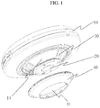
Fig. 1 is an exploded schematic view of a fisheye camera having infrared lamps. -
Fig. 2 is a sectional view of the fisheye camera having the infrared lamps. - In order to describe the purpose, technical solutions and advantages of the invention more clearly, figures and embodiments are included to describe the invention in detail.
- As shown in
Fig. 1 , the present application provides a fisheye camera having infrared lamps. The fisheye camera comprises acamera body 10, afisheye lens 20 and a plurality ofinfrared lamps 30. Wherein thefisheye lens 20 is disposed at a front end of thecamera body 10, the plurality ofinfrared lamps 30 are spaced from each other at equal angle, and are disposed at an outside of thefisheye lens 20 to irradiate the shooting range of thefisheye lens 20. - As shown in
Fig.2 , each of theinfrared lamps 30 comprises an infrared light emitting diode (LED) 31 and atransparent housing 32 enclosing the infrared LED. Wherein thetransparent housing 32 is a condensing lens, and condenses a divergent infrared lamplight of the infrared LED in a certain angle range, thereby avoiding the problem that the shooting range cannot be illuminated due to the divergent lamplight. The function of thetransparent housing 32 is the same as that of the conventional lens used individually in an array of infrared lamps, but a volume of thetransparent housing 32 is much less than that of the conventional lens. - In accordance with the above technical solutions, the fisheye camera of the present application uses the infrared lamp having lens as a night illuminating lamp. The conventional lens used in the array of infrared lamps, which is required to individually disposed, is disassembled in each of the infrared lamps to be individually used, and is integrated with each of the infrared lamps. Whereby the structure of the fisheye camera is greatly simplified. The
condensing lens 32 of each of the infrared lamps is only used to condense the lamplight of theinfrared lamp 30, thereby having a stronger pertinence, improving a condensing effect of thecondensing lens 32, and avoiding overlap irradiation among the plurality of LEDs. - Furthermore, as shown in
Fig. 1 , in order to avoid the lamplight of theinfrared lamp 30 directly irradiating into a shooting area of thefisheye lens 20, the plurality ofinfrared lamps 30 are located at a side rear of thefisheye lens 20. That is, the plurality ofinfrared lamps 30 are located at a rear of thefisheye lens 20 to avoid the infrared lamplight directly irradiating into thefisheye lens 20; simultaneously the plurality ofinfrared lamps 30 are also located at side of thefisheye lens 20 to ensure that theinfrared lamp 30 can fully illuminate the shooting area of thefisheye lens 20. - In order to reasonably dispose a location of the
infrared lamp 30, the front end of thecamera body 10 is provided with acone 11, thefisheye lens 20 is disposed at a top end of thecone 11, and the plurality ofinfrared lamps 30 are spaced from each other at equal angle and are disposed on a conical surface of thecone 11. A reasonable location relation between thefisheye lens 20 and theinfrared lamp 30 can be conveniently realized by disposing thecone 11. - Specifically, as shown in
Fig. 2 , there is an angle α between a central line A of thefisheye lens 20 and a central line B of each of theinfrared lamps 30 by disposing thecone 11. Each of theinfrared lamps 30 has an irradiating angle due to the condensing function of thecondensing lens 32, and thus the irradiating angle of each of theinfrared lamps 30 can be in the shooting range of thefisheye lens 20 by adjusting the angle α. For example, as shown inFig. 2 , the irradiating angle of each of theinfrared lamps 30 is larger than or equal to 90° mostly, and the irradiating angle of theinfrared lamp 30 can at least cover a scope from vertical direction y to horizontal direction x shown inFig. 2 . Generally, the angle α is in a range from about 40° to about 45°. - A combination of the plurality of
infrared lamps 30 can fully irradiate the shooting range of thefisheye lens 20 and decrease the overlap irradiation area between the adjacentinfrared lamps 30 by disposing the number and intervals of theinfrared lamps 30 according to the irradiating angle of theinfrared lamps 30. The influence to the image shooting caused by local lamplight having excessive brightness can be eliminated by decreasing overlap irradiation area. Wherein the adjustment of the angle α can be realized by adjusting a cone angle of thecone 11. - In order to protect the
infrared lamps 30 and beautify the appearance of the fisheye camera, the fisheye camera of the present application may further comprise an infraredtransmission lamp cover 40 placed on the plurality ofinfrared lamps 30. The infraredtransmission lamp cover 40 can transmit the infrared lamplight and protect theinfrared lamps 30 below it. Preferably, the infraredtransmission lamp cover 40 is a black infrared transmission lamp cover, and a visible light cannot transmit from the infraredtransmission lamp cover 40. Therefore, the improvement of the appearance can be realized and the transmission of the infrared lamplight cannot be influenced. - Specifically, as shown in
Fig. 2 , the infraredtransmission lamp cover 40 is an annular lamp cover placed on a conical surface of thecone 11, and thefisheye lens 10 can protrude from acentral hole 41 of the infraredtransmission lamp cover 40. Therefore, the fisheye camera of the present application has an integrative smooth outer surface. - From the above technical solutions, the fisheye camera of the present application uses an infrared lamp having lens as a night illuminating lamp. The conventional lens used in the array of the infrared lamps, which is required to individually disposed, is disassembled in each of the infrared lamps to be individually used, and is integrated with each of the infrared lamps. Whereby the structure of the fisheye camera is simplified, a condensing effect of the condensing lens is improved, and overlap irradiation among the plurality of infrared LED is avoided.
- In addition, there is an angle α between the central line of the fisheye shot and the central line of each of the infrared lamps, and an irradiating angle of each of the infrared lamps can be in a shooting range of the fisheye lens by adjusting the angle α. The number and interval of the infrared lamps can be disposed according to the irradiating angle of the infrared lamp, by which a combination of the plurality of infrared lamps can fully irradiate the shooting range of the fisheye lens and decrease the overlap irradiation area between the adjacent infrared lamps. The influence to the image shooting caused by an excessive brightness of the local lamplight can be eliminated by decreasing overlap irradiation area.
- The foregoing description, for purpose of explanation, has been described with reference to specific embodiments. However, the illustrative discussions above are not intended to be exhaustive or to limit the invention to the precise forms disclosed. Many modifications and variations are possible in view of the above teachings. The embodiments were chosen and described in order to best explain the principles of the invention and its practical applications, to thereby enable others skilled in the art to best utilize the invention and various embodiments with various modifications as are suited to the particular use contemplated.
Claims (7)
- A fisheye camera having infrared lamps, comprising: a camera body, a fisheye lens and a plurality of infrared lamps; wherein,
the fisheye lens is disposed at a front end of the camera body, and the plurality of infrared lamps are spaced from each other at equal angle and are disposed at outside of the fisheye lens; and
each of the plurality of infrared lamps comprises an infrared light emitting diode and a transparent housing for enclosing the infrared light emitting diode, and the transparent housing is a condensing lens. - The fisheye camera of claim 1, wherein the front end of the camera body is provided with a cone, the fisheye lens is disposed at a top end of the cone, and the plurality of infrared lamps are spaced from each other at equal angle and are disposed on a conical surface of the cone.
- The fisheye camera of claim 2, wherein there is an angle between a central line of the fisheye lens and a central line of each of the plurality of infrared lamps.
- The fisheye camera of claim 3, wherein the angle is in a range from about 40° to about 45°.
- The fisheye camera of claim 2, further comprising an infrared transmission lamp cover placed on the plurality of infrared lamps.
- The fisheye camera of claim 5, wherein the infrared transmission lamp cover is an annular lamp cover placed on a conical surface of the cone, and the fisheye lens protrudes from a center of the infrared transmission lamp cover.
- The fisheye camera of claim 5, wherein the infrared transmission lamp cover is a black infrared transmission lamp cover.
Applications Claiming Priority (2)
| Application Number | Priority Date | Filing Date | Title |
|---|---|---|---|
| CN201420385848.6U CN203968223U (en) | 2014-07-11 | 2014-07-11 | A kind of flake video camera with infrared lamp |
| PCT/CN2015/072512 WO2016004761A1 (en) | 2014-07-11 | 2015-02-09 | Fisheye camera with infrared lamp |
Publications (3)
| Publication Number | Publication Date |
|---|---|
| EP3032819A1 true EP3032819A1 (en) | 2016-06-15 |
| EP3032819A4 EP3032819A4 (en) | 2016-07-27 |
| EP3032819B1 EP3032819B1 (en) | 2019-06-26 |
Family
ID=51928760
Family Applications (1)
| Application Number | Title | Priority Date | Filing Date |
|---|---|---|---|
| EP15818423.4A Active EP3032819B1 (en) | 2014-07-11 | 2015-02-09 | Fisheye camera with infrared lamp |
Country Status (4)
| Country | Link |
|---|---|
| US (1) | US20160205318A1 (en) |
| EP (1) | EP3032819B1 (en) |
| CN (1) | CN203968223U (en) |
| WO (1) | WO2016004761A1 (en) |
Families Citing this family (20)
| Publication number | Priority date | Publication date | Assignee | Title |
|---|---|---|---|---|
| US9071740B1 (en) | 2011-10-28 | 2015-06-30 | Google Inc. | Modular camera system |
| US9197686B1 (en) | 2012-01-06 | 2015-11-24 | Google Inc. | Backfill of video stream |
| CN203968223U (en) * | 2014-07-11 | 2014-11-26 | 杭州海康威视数字技术股份有限公司 | A kind of flake video camera with infrared lamp |
| WO2016037114A1 (en) * | 2014-09-05 | 2016-03-10 | 360Fly,Inc. | Panoramic camera systems |
| US9544485B2 (en) * | 2015-05-27 | 2017-01-10 | Google Inc. | Multi-mode LED illumination system |
| US9386230B1 (en) | 2015-06-12 | 2016-07-05 | Google Inc. | Day and night detection based on one or more of illuminant detection, lux level detection, and tiling |
| US9554063B2 (en) | 2015-06-12 | 2017-01-24 | Google Inc. | Using infrared images of a monitored scene to identify windows |
| US9454820B1 (en) | 2015-06-12 | 2016-09-27 | Google Inc. | Using a scene illuminating infrared emitter array in a video monitoring camera for depth determination |
| US20170195563A1 (en) * | 2016-01-05 | 2017-07-06 | 360fly, Inc. | Body-mountable panoramic cameras with wide fields of view |
| WO2018049189A1 (en) * | 2016-09-09 | 2018-03-15 | Donald Danforth Plant Science Center | Integrated field phenotyping and management platform for crop development and precision agriculture |
| US10180615B2 (en) | 2016-10-31 | 2019-01-15 | Google Llc | Electrochromic filtering in a camera |
| US10683962B2 (en) | 2017-05-25 | 2020-06-16 | Google Llc | Thermal management for a compact electronic device |
| US10972685B2 (en) | 2017-05-25 | 2021-04-06 | Google Llc | Video camera assembly having an IR reflector |
| US10819921B2 (en) * | 2017-05-25 | 2020-10-27 | Google Llc | Camera assembly having a single-piece cover element |
| CN110324527A (en) * | 2018-03-29 | 2019-10-11 | 富泰华工业(深圳)有限公司 | Filming apparatus |
| CN208174831U (en) * | 2018-05-30 | 2018-11-30 | 杭州海康威视数字技术股份有限公司 | Thermal camera |
| GB2574417B (en) * | 2018-06-05 | 2021-03-03 | Dyson Technology Ltd | A vision system for a mobile robot |
| CN109348111A (en) * | 2018-11-23 | 2019-02-15 | 意诺科技有限公司 | A kind of flake night vision cam and flake night viewing camera |
| KR102124884B1 (en) * | 2019-01-22 | 2020-06-23 | 주식회사 아이디스 | Fish eye camera |
| US11825182B2 (en) * | 2020-10-12 | 2023-11-21 | Waymo Llc | Camera module with IR LEDs for uniform illumination |
Family Cites Families (12)
| Publication number | Priority date | Publication date | Assignee | Title |
|---|---|---|---|---|
| JP4899534B2 (en) * | 2006-02-28 | 2012-03-21 | ソニー株式会社 | Surveillance camera |
| JP4566929B2 (en) * | 2006-03-03 | 2010-10-20 | 富士通株式会社 | Imaging device |
| JP4804962B2 (en) * | 2006-03-03 | 2011-11-02 | 富士通株式会社 | Imaging device |
| WO2007115570A1 (en) * | 2006-04-07 | 2007-10-18 | Novarix Ltd | Vein navigation device |
| US8188430B2 (en) * | 2008-05-22 | 2012-05-29 | International Electronic Machines Corporation | Omnidirectional monitoring using near-infrared electromagnetic radiation |
| CN201608782U (en) * | 2010-03-23 | 2010-10-13 | 杨贵寅 | Intelligent infrared dome camera |
| KR20140033527A (en) * | 2012-08-14 | 2014-03-19 | 삼성전자주식회사 | Condensing lens and lighting device including the same |
| CN202818504U (en) * | 2012-09-24 | 2013-03-20 | 天津市亚安科技股份有限公司 | High-definition panoramic automatic tracking monitoring device |
| US9479697B2 (en) * | 2012-10-23 | 2016-10-25 | Bounce Imaging, Inc. | Systems, methods and media for generating a panoramic view |
| CN203279068U (en) * | 2013-06-04 | 2013-11-06 | 四川艾普视达数码科技有限公司 | Infrared camera unit having fixed-point refining camera-shooting function |
| CN103297661A (en) * | 2013-06-04 | 2013-09-11 | 四川艾普视达数码科技有限公司 | Infrared monitoring device with fixed-point thinning camera shooting function |
| CN203968223U (en) * | 2014-07-11 | 2014-11-26 | 杭州海康威视数字技术股份有限公司 | A kind of flake video camera with infrared lamp |
-
2014
- 2014-07-11 CN CN201420385848.6U patent/CN203968223U/en active Active
-
2015
- 2015-02-09 US US14/899,058 patent/US20160205318A1/en not_active Abandoned
- 2015-02-09 WO PCT/CN2015/072512 patent/WO2016004761A1/en active Application Filing
- 2015-02-09 EP EP15818423.4A patent/EP3032819B1/en active Active
Also Published As
| Publication number | Publication date |
|---|---|
| EP3032819A4 (en) | 2016-07-27 |
| WO2016004761A1 (en) | 2016-01-14 |
| US20160205318A1 (en) | 2016-07-14 |
| EP3032819B1 (en) | 2019-06-26 |
| CN203968223U (en) | 2014-11-26 |
Similar Documents
| Publication | Publication Date | Title |
|---|---|---|
| EP3032819B1 (en) | Fisheye camera with infrared lamp | |
| CN108234836B (en) | Camera arrangement with an illuminator | |
| US11131902B2 (en) | Electronic device and capturing apparatus for electronic device | |
| EP2256403A3 (en) | Self-ballasted LED lamp | |
| GB2460150A (en) | Surveillance camera assembly in which illumination devices rotate along with camera lens | |
| US9453622B2 (en) | Lens and LED module having the same | |
| WO2015153564A3 (en) | Annular illumination structure | |
| US20140071337A1 (en) | Electronic device with camera module | |
| US9827898B2 (en) | Vehicle light assembly with multiple light arrays | |
| CN204313074U (en) | Can the lighting device of zoom light modulation | |
| US20130155233A1 (en) | Monitoring camera | |
| EP3260767A1 (en) | Led bar lighting with uniform illumination | |
| USD873692S1 (en) | Warning light assembly | |
| CN104917858A (en) | Mobile phone light gathering attachment | |
| US20170241610A1 (en) | Car led light capable of changing color temperature | |
| CN111350963A (en) | High-efficiency energy-saving lighting lamp | |
| KR200479099Y1 (en) | Led light for camera | |
| CN207555370U (en) | A kind of Rimless LED floodlight tubes | |
| CN203761467U (en) | Lighting type computer network video camera | |
| US8275252B1 (en) | Camera | |
| RU2015139856A (en) | UNDERWATER LIGHT AND SECURITY SYSTEM | |
| CN103423645A (en) | LED (Light-Emitting Diode) annular light source with improved structure | |
| CN210662502U (en) | Infrared spotlight | |
| US20160238205A1 (en) | Collapsible Shelter Light | |
| CN203231167U (en) | Lamp |
Legal Events
| Date | Code | Title | Description |
|---|---|---|---|
| PUAI | Public reference made under article 153(3) epc to a published international application that has entered the european phase |
Free format text: ORIGINAL CODE: 0009012 |
|
| 17P | Request for examination filed |
Effective date: 20160307 |
|
| AK | Designated contracting states |
Kind code of ref document: A1 Designated state(s): AL AT BE BG CH CY CZ DE DK EE ES FI FR GB GR HR HU IE IS IT LI LT LU LV MC MK MT NL NO PL PT RO RS SE SI SK SM TR |
|
| AX | Request for extension of the european patent |
Extension state: BA ME |
|
| A4 | Supplementary search report drawn up and despatched |
Effective date: 20160627 |
|
| RIC1 | Information provided on ipc code assigned before grant |
Ipc: G08B 13/196 20060101ALI20160621BHEP Ipc: H04N 5/232 20060101ALI20160621BHEP Ipc: H04N 5/225 20060101AFI20160621BHEP Ipc: H04N 5/235 20060101ALI20160621BHEP Ipc: H04N 5/33 20060101ALI20160621BHEP |
|
| DAX | Request for extension of the european patent (deleted) | ||
| STAA | Information on the status of an ep patent application or granted ep patent |
Free format text: STATUS: EXAMINATION IS IN PROGRESS |
|
| 17Q | First examination report despatched |
Effective date: 20180103 |
|
| GRAP | Despatch of communication of intention to grant a patent |
Free format text: ORIGINAL CODE: EPIDOSNIGR1 |
|
| STAA | Information on the status of an ep patent application or granted ep patent |
Free format text: STATUS: GRANT OF PATENT IS INTENDED |
|
| INTG | Intention to grant announced |
Effective date: 20190206 |
|
| RAP1 | Party data changed (applicant data changed or rights of an application transferred) |
Owner name: HANGZHOU HIKVISION DIGITAL TECHNOLOGY CO., LTD. |
|
| GRAS | Grant fee paid |
Free format text: ORIGINAL CODE: EPIDOSNIGR3 |
|
| GRAA | (expected) grant |
Free format text: ORIGINAL CODE: 0009210 |
|
| STAA | Information on the status of an ep patent application or granted ep patent |
Free format text: STATUS: THE PATENT HAS BEEN GRANTED |
|
| AK | Designated contracting states |
Kind code of ref document: B1 Designated state(s): AL AT BE BG CH CY CZ DE DK EE ES FI FR GB GR HR HU IE IS IT LI LT LU LV MC MK MT NL NO PL PT RO RS SE SI SK SM TR |
|
| REG | Reference to a national code |
Ref country code: GB Ref legal event code: FG4D |
|
| REG | Reference to a national code |
Ref country code: CH Ref legal event code: EP |
|
| REG | Reference to a national code |
Ref country code: AT Ref legal event code: REF Ref document number: 1149678 Country of ref document: AT Kind code of ref document: T Effective date: 20190715 |
|
| REG | Reference to a national code |
Ref country code: DE Ref legal event code: R096 Ref document number: 602015032828 Country of ref document: DE |
|
| REG | Reference to a national code |
Ref country code: IE Ref legal event code: FG4D |
|
| REG | Reference to a national code |
Ref country code: NL Ref legal event code: MP Effective date: 20190626 |
|
| PG25 | Lapsed in a contracting state [announced via postgrant information from national office to epo] |
Ref country code: SE Free format text: LAPSE BECAUSE OF FAILURE TO SUBMIT A TRANSLATION OF THE DESCRIPTION OR TO PAY THE FEE WITHIN THE PRESCRIBED TIME-LIMIT Effective date: 20190626 Ref country code: HR Free format text: LAPSE BECAUSE OF FAILURE TO SUBMIT A TRANSLATION OF THE DESCRIPTION OR TO PAY THE FEE WITHIN THE PRESCRIBED TIME-LIMIT Effective date: 20190626 Ref country code: AL Free format text: LAPSE BECAUSE OF FAILURE TO SUBMIT A TRANSLATION OF THE DESCRIPTION OR TO PAY THE FEE WITHIN THE PRESCRIBED TIME-LIMIT Effective date: 20190626 Ref country code: FI Free format text: LAPSE BECAUSE OF FAILURE TO SUBMIT A TRANSLATION OF THE DESCRIPTION OR TO PAY THE FEE WITHIN THE PRESCRIBED TIME-LIMIT Effective date: 20190626 Ref country code: NO Free format text: LAPSE BECAUSE OF FAILURE TO SUBMIT A TRANSLATION OF THE DESCRIPTION OR TO PAY THE FEE WITHIN THE PRESCRIBED TIME-LIMIT Effective date: 20190926 Ref country code: LT Free format text: LAPSE BECAUSE OF FAILURE TO SUBMIT A TRANSLATION OF THE DESCRIPTION OR TO PAY THE FEE WITHIN THE PRESCRIBED TIME-LIMIT Effective date: 20190626 |
|
| REG | Reference to a national code |
Ref country code: LT Ref legal event code: MG4D |
|
| PG25 | Lapsed in a contracting state [announced via postgrant information from national office to epo] |
Ref country code: GR Free format text: LAPSE BECAUSE OF FAILURE TO SUBMIT A TRANSLATION OF THE DESCRIPTION OR TO PAY THE FEE WITHIN THE PRESCRIBED TIME-LIMIT Effective date: 20190927 Ref country code: RS Free format text: LAPSE BECAUSE OF FAILURE TO SUBMIT A TRANSLATION OF THE DESCRIPTION OR TO PAY THE FEE WITHIN THE PRESCRIBED TIME-LIMIT Effective date: 20190626 Ref country code: BG Free format text: LAPSE BECAUSE OF FAILURE TO SUBMIT A TRANSLATION OF THE DESCRIPTION OR TO PAY THE FEE WITHIN THE PRESCRIBED TIME-LIMIT Effective date: 20190926 Ref country code: LV Free format text: LAPSE BECAUSE OF FAILURE TO SUBMIT A TRANSLATION OF THE DESCRIPTION OR TO PAY THE FEE WITHIN THE PRESCRIBED TIME-LIMIT Effective date: 20190626 |
|
| REG | Reference to a national code |
Ref country code: AT Ref legal event code: MK05 Ref document number: 1149678 Country of ref document: AT Kind code of ref document: T Effective date: 20190626 |
|
| PG25 | Lapsed in a contracting state [announced via postgrant information from national office to epo] |
Ref country code: NL Free format text: LAPSE BECAUSE OF FAILURE TO SUBMIT A TRANSLATION OF THE DESCRIPTION OR TO PAY THE FEE WITHIN THE PRESCRIBED TIME-LIMIT Effective date: 20190626 Ref country code: AT Free format text: LAPSE BECAUSE OF FAILURE TO SUBMIT A TRANSLATION OF THE DESCRIPTION OR TO PAY THE FEE WITHIN THE PRESCRIBED TIME-LIMIT Effective date: 20190626 Ref country code: EE Free format text: LAPSE BECAUSE OF FAILURE TO SUBMIT A TRANSLATION OF THE DESCRIPTION OR TO PAY THE FEE WITHIN THE PRESCRIBED TIME-LIMIT Effective date: 20190626 Ref country code: CZ Free format text: LAPSE BECAUSE OF FAILURE TO SUBMIT A TRANSLATION OF THE DESCRIPTION OR TO PAY THE FEE WITHIN THE PRESCRIBED TIME-LIMIT Effective date: 20190626 Ref country code: RO Free format text: LAPSE BECAUSE OF FAILURE TO SUBMIT A TRANSLATION OF THE DESCRIPTION OR TO PAY THE FEE WITHIN THE PRESCRIBED TIME-LIMIT Effective date: 20190626 Ref country code: SK Free format text: LAPSE BECAUSE OF FAILURE TO SUBMIT A TRANSLATION OF THE DESCRIPTION OR TO PAY THE FEE WITHIN THE PRESCRIBED TIME-LIMIT Effective date: 20190626 Ref country code: PT Free format text: LAPSE BECAUSE OF FAILURE TO SUBMIT A TRANSLATION OF THE DESCRIPTION OR TO PAY THE FEE WITHIN THE PRESCRIBED TIME-LIMIT Effective date: 20191028 |
|
| PG25 | Lapsed in a contracting state [announced via postgrant information from national office to epo] |
Ref country code: IS Free format text: LAPSE BECAUSE OF FAILURE TO SUBMIT A TRANSLATION OF THE DESCRIPTION OR TO PAY THE FEE WITHIN THE PRESCRIBED TIME-LIMIT Effective date: 20191026 Ref country code: SM Free format text: LAPSE BECAUSE OF FAILURE TO SUBMIT A TRANSLATION OF THE DESCRIPTION OR TO PAY THE FEE WITHIN THE PRESCRIBED TIME-LIMIT Effective date: 20190626 Ref country code: ES Free format text: LAPSE BECAUSE OF FAILURE TO SUBMIT A TRANSLATION OF THE DESCRIPTION OR TO PAY THE FEE WITHIN THE PRESCRIBED TIME-LIMIT Effective date: 20190626 |
|
| PG25 | Lapsed in a contracting state [announced via postgrant information from national office to epo] |
Ref country code: TR Free format text: LAPSE BECAUSE OF FAILURE TO SUBMIT A TRANSLATION OF THE DESCRIPTION OR TO PAY THE FEE WITHIN THE PRESCRIBED TIME-LIMIT Effective date: 20190626 |
|
| PG25 | Lapsed in a contracting state [announced via postgrant information from national office to epo] |
Ref country code: DK Free format text: LAPSE BECAUSE OF FAILURE TO SUBMIT A TRANSLATION OF THE DESCRIPTION OR TO PAY THE FEE WITHIN THE PRESCRIBED TIME-LIMIT Effective date: 20190626 Ref country code: PL Free format text: LAPSE BECAUSE OF FAILURE TO SUBMIT A TRANSLATION OF THE DESCRIPTION OR TO PAY THE FEE WITHIN THE PRESCRIBED TIME-LIMIT Effective date: 20190626 |
|
| PG25 | Lapsed in a contracting state [announced via postgrant information from national office to epo] |
Ref country code: IS Free format text: LAPSE BECAUSE OF FAILURE TO SUBMIT A TRANSLATION OF THE DESCRIPTION OR TO PAY THE FEE WITHIN THE PRESCRIBED TIME-LIMIT Effective date: 20200224 |
|
| REG | Reference to a national code |
Ref country code: DE Ref legal event code: R097 Ref document number: 602015032828 Country of ref document: DE |
|
| PLBE | No opposition filed within time limit |
Free format text: ORIGINAL CODE: 0009261 |
|
| STAA | Information on the status of an ep patent application or granted ep patent |
Free format text: STATUS: NO OPPOSITION FILED WITHIN TIME LIMIT |
|
| PG2D | Information on lapse in contracting state deleted |
Ref country code: IS |
|
| 26N | No opposition filed |
Effective date: 20200603 |
|
| PG25 | Lapsed in a contracting state [announced via postgrant information from national office to epo] |
Ref country code: SI Free format text: LAPSE BECAUSE OF FAILURE TO SUBMIT A TRANSLATION OF THE DESCRIPTION OR TO PAY THE FEE WITHIN THE PRESCRIBED TIME-LIMIT Effective date: 20190626 |
|
| REG | Reference to a national code |
Ref country code: CH Ref legal event code: PL |
|
| GBPC | Gb: european patent ceased through non-payment of renewal fee |
Effective date: 20200209 |
|
| REG | Reference to a national code |
Ref country code: BE Ref legal event code: MM Effective date: 20200229 |
|
| PG25 | Lapsed in a contracting state [announced via postgrant information from national office to epo] |
Ref country code: MC Free format text: LAPSE BECAUSE OF FAILURE TO SUBMIT A TRANSLATION OF THE DESCRIPTION OR TO PAY THE FEE WITHIN THE PRESCRIBED TIME-LIMIT Effective date: 20190626 Ref country code: LU Free format text: LAPSE BECAUSE OF NON-PAYMENT OF DUE FEES Effective date: 20200209 |
|
| PG25 | Lapsed in a contracting state [announced via postgrant information from national office to epo] |
Ref country code: LI Free format text: LAPSE BECAUSE OF NON-PAYMENT OF DUE FEES Effective date: 20200229 Ref country code: CH Free format text: LAPSE BECAUSE OF NON-PAYMENT OF DUE FEES Effective date: 20200229 |
|
| PG25 | Lapsed in a contracting state [announced via postgrant information from national office to epo] |
Ref country code: FR Free format text: LAPSE BECAUSE OF NON-PAYMENT OF DUE FEES Effective date: 20200229 Ref country code: IE Free format text: LAPSE BECAUSE OF NON-PAYMENT OF DUE FEES Effective date: 20200209 Ref country code: GB Free format text: LAPSE BECAUSE OF NON-PAYMENT OF DUE FEES Effective date: 20200209 |
|
| PG25 | Lapsed in a contracting state [announced via postgrant information from national office to epo] |
Ref country code: BE Free format text: LAPSE BECAUSE OF NON-PAYMENT OF DUE FEES Effective date: 20200229 |
|
| PG25 | Lapsed in a contracting state [announced via postgrant information from national office to epo] |
Ref country code: MT Free format text: LAPSE BECAUSE OF FAILURE TO SUBMIT A TRANSLATION OF THE DESCRIPTION OR TO PAY THE FEE WITHIN THE PRESCRIBED TIME-LIMIT Effective date: 20190626 Ref country code: CY Free format text: LAPSE BECAUSE OF FAILURE TO SUBMIT A TRANSLATION OF THE DESCRIPTION OR TO PAY THE FEE WITHIN THE PRESCRIBED TIME-LIMIT Effective date: 20190626 |
|
| PG25 | Lapsed in a contracting state [announced via postgrant information from national office to epo] |
Ref country code: MK Free format text: LAPSE BECAUSE OF FAILURE TO SUBMIT A TRANSLATION OF THE DESCRIPTION OR TO PAY THE FEE WITHIN THE PRESCRIBED TIME-LIMIT Effective date: 20190626 |
|
| REG | Reference to a national code |
Ref country code: DE Ref legal event code: R079 Ref document number: 602015032828 Country of ref document: DE Free format text: PREVIOUS MAIN CLASS: H04N0005225000 Ipc: H04N0023000000 |
|
| PGFP | Annual fee paid to national office [announced via postgrant information from national office to epo] |
Ref country code: IT Payment date: 20230209 Year of fee payment: 9 Ref country code: DE Payment date: 20230207 Year of fee payment: 9 |
|
| P01 | Opt-out of the competence of the unified patent court (upc) registered |
Effective date: 20230424 |
|
| PGFP | Annual fee paid to national office [announced via postgrant information from national office to epo] |
Ref country code: DE Payment date: 20240213 Year of fee payment: 10 |