EP3032723B1 - Pompe et appareil de nettoyage - Google Patents
Pompe et appareil de nettoyage Download PDFInfo
- Publication number
- EP3032723B1 EP3032723B1 EP15198537.1A EP15198537A EP3032723B1 EP 3032723 B1 EP3032723 B1 EP 3032723B1 EP 15198537 A EP15198537 A EP 15198537A EP 3032723 B1 EP3032723 B1 EP 3032723B1
- Authority
- EP
- European Patent Office
- Prior art keywords
- pump
- rotor
- stator
- bearing
- switch
- Prior art date
- Legal status (The legal status is an assumption and is not a legal conclusion. Google has not performed a legal analysis and makes no representation as to the accuracy of the status listed.)
- Active
Links
- 238000004140 cleaning Methods 0.000 title claims description 23
- 238000004804 winding Methods 0.000 claims description 58
- XLYOFNOQVPJJNP-UHFFFAOYSA-N water Substances O XLYOFNOQVPJJNP-UHFFFAOYSA-N 0.000 claims description 16
- 230000002457 bidirectional effect Effects 0.000 claims description 15
- 239000000758 substrate Substances 0.000 claims description 14
- 238000006243 chemical reaction Methods 0.000 claims description 11
- 230000001360 synchronised effect Effects 0.000 claims description 8
- 239000006096 absorbing agent Substances 0.000 claims description 6
- 230000035939 shock Effects 0.000 claims description 6
- 238000001746 injection moulding Methods 0.000 claims description 4
- 238000004891 communication Methods 0.000 claims description 3
- 238000005086 pumping Methods 0.000 claims description 2
- 238000000465 moulding Methods 0.000 description 7
- 239000004020 conductor Substances 0.000 description 4
- 239000000463 material Substances 0.000 description 4
- 238000000034 method Methods 0.000 description 3
- 238000007789 sealing Methods 0.000 description 3
- XUIMIQQOPSSXEZ-UHFFFAOYSA-N Silicon Chemical compound [Si] XUIMIQQOPSSXEZ-UHFFFAOYSA-N 0.000 description 2
- 238000010586 diagram Methods 0.000 description 2
- 230000001012 protector Effects 0.000 description 2
- 229910052710 silicon Inorganic materials 0.000 description 2
- 239000010703 silicon Substances 0.000 description 2
- 239000011800 void material Substances 0.000 description 2
- 238000010276 construction Methods 0.000 description 1
- 230000007423 decrease Effects 0.000 description 1
- 238000005265 energy consumption Methods 0.000 description 1
- 230000002708 enhancing effect Effects 0.000 description 1
- 239000012530 fluid Substances 0.000 description 1
- 238000003475 lamination Methods 0.000 description 1
- 239000007769 metal material Substances 0.000 description 1
- 238000012986 modification Methods 0.000 description 1
- 230000004048 modification Effects 0.000 description 1
- 230000010355 oscillation Effects 0.000 description 1
- 239000000843 powder Substances 0.000 description 1
Images


Classifications
-
- F—MECHANICAL ENGINEERING; LIGHTING; HEATING; WEAPONS; BLASTING
- F04—POSITIVE - DISPLACEMENT MACHINES FOR LIQUIDS; PUMPS FOR LIQUIDS OR ELASTIC FLUIDS
- F04D—NON-POSITIVE-DISPLACEMENT PUMPS
- F04D13/00—Pumping installations or systems
- F04D13/02—Units comprising pumps and their driving means
- F04D13/06—Units comprising pumps and their driving means the pump being electrically driven
-
- H—ELECTRICITY
- H02—GENERATION; CONVERSION OR DISTRIBUTION OF ELECTRIC POWER
- H02K—DYNAMO-ELECTRIC MACHINES
- H02K29/00—Motors or generators having non-mechanical commutating devices, e.g. discharge tubes or semiconductor devices
- H02K29/03—Motors or generators having non-mechanical commutating devices, e.g. discharge tubes or semiconductor devices with a magnetic circuit specially adapted for avoiding torque ripples or self-starting problems
-
- F—MECHANICAL ENGINEERING; LIGHTING; HEATING; WEAPONS; BLASTING
- F04—POSITIVE - DISPLACEMENT MACHINES FOR LIQUIDS; PUMPS FOR LIQUIDS OR ELASTIC FLUIDS
- F04D—NON-POSITIVE-DISPLACEMENT PUMPS
- F04D13/00—Pumping installations or systems
- F04D13/02—Units comprising pumps and their driving means
- F04D13/06—Units comprising pumps and their driving means the pump being electrically driven
- F04D13/0606—Canned motor pumps
-
- A—HUMAN NECESSITIES
- A47—FURNITURE; DOMESTIC ARTICLES OR APPLIANCES; COFFEE MILLS; SPICE MILLS; SUCTION CLEANERS IN GENERAL
- A47L—DOMESTIC WASHING OR CLEANING; SUCTION CLEANERS IN GENERAL
- A47L15/00—Washing or rinsing machines for crockery or tableware
- A47L15/42—Details
- A47L15/4214—Water supply, recirculation or discharge arrangements; Devices therefor
- A47L15/4225—Arrangements or adaption of recirculation or discharge pumps
-
- D—TEXTILES; PAPER
- D06—TREATMENT OF TEXTILES OR THE LIKE; LAUNDERING; FLEXIBLE MATERIALS NOT OTHERWISE PROVIDED FOR
- D06F—LAUNDERING, DRYING, IRONING, PRESSING OR FOLDING TEXTILE ARTICLES
- D06F39/00—Details of washing machines not specific to a single type of machines covered by groups D06F9/00 - D06F27/00
- D06F39/08—Liquid supply or discharge arrangements
- D06F39/083—Liquid discharge or recirculation arrangements
- D06F39/085—Arrangements or adaptations of pumps
-
- F—MECHANICAL ENGINEERING; LIGHTING; HEATING; WEAPONS; BLASTING
- F04—POSITIVE - DISPLACEMENT MACHINES FOR LIQUIDS; PUMPS FOR LIQUIDS OR ELASTIC FLUIDS
- F04D—NON-POSITIVE-DISPLACEMENT PUMPS
- F04D1/00—Radial-flow pumps, e.g. centrifugal pumps; Helico-centrifugal pumps
-
- F—MECHANICAL ENGINEERING; LIGHTING; HEATING; WEAPONS; BLASTING
- F04—POSITIVE - DISPLACEMENT MACHINES FOR LIQUIDS; PUMPS FOR LIQUIDS OR ELASTIC FLUIDS
- F04D—NON-POSITIVE-DISPLACEMENT PUMPS
- F04D13/00—Pumping installations or systems
- F04D13/02—Units comprising pumps and their driving means
- F04D13/06—Units comprising pumps and their driving means the pump being electrically driven
- F04D13/0606—Canned motor pumps
- F04D13/0626—Details of the can
-
- F—MECHANICAL ENGINEERING; LIGHTING; HEATING; WEAPONS; BLASTING
- F04—POSITIVE - DISPLACEMENT MACHINES FOR LIQUIDS; PUMPS FOR LIQUIDS OR ELASTIC FLUIDS
- F04D—NON-POSITIVE-DISPLACEMENT PUMPS
- F04D13/00—Pumping installations or systems
- F04D13/02—Units comprising pumps and their driving means
- F04D13/06—Units comprising pumps and their driving means the pump being electrically driven
- F04D13/0606—Canned motor pumps
- F04D13/064—Details of the magnetic circuit
-
- F—MECHANICAL ENGINEERING; LIGHTING; HEATING; WEAPONS; BLASTING
- F04—POSITIVE - DISPLACEMENT MACHINES FOR LIQUIDS; PUMPS FOR LIQUIDS OR ELASTIC FLUIDS
- F04D—NON-POSITIVE-DISPLACEMENT PUMPS
- F04D29/00—Details, component parts, or accessories
- F04D29/18—Rotors
- F04D29/22—Rotors specially for centrifugal pumps
- F04D29/24—Vanes
- F04D29/242—Geometry, shape
-
- H—ELECTRICITY
- H02—GENERATION; CONVERSION OR DISTRIBUTION OF ELECTRIC POWER
- H02K—DYNAMO-ELECTRIC MACHINES
- H02K1/00—Details of the magnetic circuit
- H02K1/06—Details of the magnetic circuit characterised by the shape, form or construction
- H02K1/22—Rotating parts of the magnetic circuit
- H02K1/27—Rotor cores with permanent magnets
-
- H—ELECTRICITY
- H02—GENERATION; CONVERSION OR DISTRIBUTION OF ELECTRIC POWER
- H02K—DYNAMO-ELECTRIC MACHINES
- H02K21/00—Synchronous motors having permanent magnets; Synchronous generators having permanent magnets
- H02K21/12—Synchronous motors having permanent magnets; Synchronous generators having permanent magnets with stationary armatures and rotating magnets
-
- H—ELECTRICITY
- H02—GENERATION; CONVERSION OR DISTRIBUTION OF ELECTRIC POWER
- H02K—DYNAMO-ELECTRIC MACHINES
- H02K7/00—Arrangements for handling mechanical energy structurally associated with dynamo-electric machines, e.g. structural association with mechanical driving motors or auxiliary dynamo-electric machines
- H02K7/14—Structural association with mechanical loads, e.g. with hand-held machine tools or fans
-
- F—MECHANICAL ENGINEERING; LIGHTING; HEATING; WEAPONS; BLASTING
- F05—INDEXING SCHEMES RELATING TO ENGINES OR PUMPS IN VARIOUS SUBCLASSES OF CLASSES F01-F04
- F05D—INDEXING SCHEME FOR ASPECTS RELATING TO NON-POSITIVE-DISPLACEMENT MACHINES OR ENGINES, GAS-TURBINES OR JET-PROPULSION PLANTS
- F05D2260/00—Function
- F05D2260/85—Starting
Definitions
- This invention relates to pumps and in particular, to a drain pump for use in dishwashers or laundry machines.
- the electromagnet of the stator creates an alternating magnetic field which pulls the permanent magnetic rotor to oscillate.
- the motor is usually configured to have a low starting point, which makes the motor unable to operate at high efficiency operation point and hence leads to a low efficiency.
- the impeller driven by the rotor usually utilizes straight type radial blades, which also leads to low efficiency of the pump.
- a pump which includes a pump housing having a pump chamber, an inlet and an outlet in communication with the pump chamber, a motor, and an impeller disposed in the pump chamber.
- the motor includes a stator and a rotor rotatable relative to the stator, the stator comprising a stator core and stator windings wound around the stator core and powered by an AC power supply.
- the impeller is fixedly connected to a shaft of the rotor so as to always synchronously rotate along with the rotary shaft.
- a circuit board having a drive circuit which energizes the stator windings in a predetermined manner ensures that the stator windings drag the rotor to rotate only in a fixed starting direction during a starting phase of the synchronous motor.
- the drive circuit comprises a controllable bidirectional AC switch, an AC-DC conversion circuit, a position sensor for detecting the magnetic pole position of the rotor, and a switch control circuit configured to control the controllable bidirectional AC switch to be switched between a switch-on state and a switch-off state in a preset way, based on the magnetic pole position and polarity information of the AC power supply; characterized in that the controllable bidirectional AC switch is connected in parallel with the stator windings and an AC power supply connected in series between two nodes, and the AC-DC conversion circuit connected in parallel with the controllable bidirectional AC switch
- the rotor comprises a rotary shaft and a magnet fixed to the rotary shaft.
- the rotor has the fixed starting direction and rotates at a constant speed of 60f/p RPM during a steady state, where f is the frequency of the alternating current power supply, and p is the number of pole pairs of the permanent magnetic rotor.
- the impeller comprises a substrate and a plurality of curved blades mounted to the substrate spacedly in a circumferential direction.
- the impeller comprises a substrate, and a group of long curved blades and a group of short curved blades mounted to the substrate spacedly in a circumferential direction.
- a mounting post is disposed at a central area of the substrate, one end of the rotary shaft is fixed to the mounting post via a shaft sleeve, and the mounting post, the shaft sleeve and an injection molding portion at an inner side of the shaft sleeve cooperatively form a continuous closed end surface at an axial end of the mounting post away from the motor.
- the pump housing includes a cover body and a bottom plate mounted to the cover body, and the bottom plate includes a pump chamber bottom wall having an opening, and a rotor housing extending integrally axially and outwardly from the opening.
- an end cap is fixed within one end of the rotor housing adjacent the opening, and opposite ends of the rotary shaft are respectively supported by a first bearing disposed in the end cap and a second bearing disposed at another end of the rotor housing away from the opening.
- the first bearing is mounted to the end cap via a shock absorber.
- the first bearing is cylindrical in shape and includes a ridge extending circumferentially on an outer surface of the first bearing, and an inner surface of the shock absorber forms a groove for engaging with the ridge.
- the second bearing is supported by a bearing seat integrally formed with the rotor housing, and a plurality of internal teeth is formed on an inner surface of the bearing seat.
- opposite ends of the rotary shaft are respectively supported by two bearings, the two bearings are supported by two support members, and at least one of the two bearings is in non-continuous contact with a corresponding one of the support members along a circumferential direction.
- a cleaning apparatus which includes a cleaning chamber, a water supply passage for supplying cleaning water to the cleaning chamber, a drain passage for drainage of water, and a drain pump for pumping the cleaning water in the cleaning chamber to the drain passage.
- the drain pump comprises the features of the pumps.
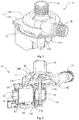
- a pump 10 includes a pump housing 14 having a pump chamber 12, an inlet 16 and an outlet 18 in fluid communication with the pump chamber 12, an impeller 20 rotatably disposed in the pump chamber 12, and a motor 22 for driving the impeller 20.
- the motor 22 is a single phase synchronous motor including a stator and a rotor 26 rotatable relative to the stator.
- the rotor 26 includes a rotary shaft 28 and magnets 30 fixed to the rotary shaft 28.
- the rotor 26 includes two permanent magnets 30 forming two poles with opposite polarities.
- the permanent magnets 30 are fixed to the rotary shaft 28 by an over-molding piece 32.
- the over-molding piece 32 includes an inner ring 34, an outer ring 36, and two end plates 38 disposed to interconnect opposite axial ends of the inner and outer rings 34, 36.
- the outer ring 36 is over-molded on the magnets 30 and has an outer surface concentric with the rotary shaft 28.
- the inner ring 34 is over-molded on the rotary shaft 28.
- the two magnets 30 are fixed radially between the inner ring 34 and the outer ring 36 and fixed axially between the two end plates 38.
- a concave-convex structure 39 is formed on an outer surface of the rotary shaft 28 to strengthen the bonding force between the over-molding piece 32 and the rotary shaft 28.
- Each magnet 30 covers a half of the circumference along the circumferential direction, including a radial outer surface 40, a radial inner surface 42, and two coplanar connecting surfaces 44 that connect the radial outer surface 40 and the radial inner surface 42 at opposite ends of the magnet 30.
- the radial outer surface 40 includes an arc section 46 and two plane sections 48 extending from opposite circumferential ends of the arc portion 46 to the connecting surfaces 44.
- the magnets 30 may be sintered from powder material.
- the plane sections 48 may be used to position the formed magnet 30 for subsequent processing such as grinding.
- the arc section 46 of the outer surface 40 may be concentric with the radial inner surface 42.
- the radial inner surfaces 42 of the two magnets 30 cooperatively define an inner bore 50 for the rotary shaft 28 to pass therethrough.
- the inner ring 34 of the over-molding piece 32 is formed between the radial inner surface 42 and the rotary shaft 28.
- a ratio of a pole arc angle ⁇ of each magnet 30 to the angle of 180 degrees is in the range of 0.75 to 0.95, and more preferably in the range of 0.9 to 0.95.
- the term "pole arc angle” as used herein refers to the angle formed by hypothetical lines connecting the two circumferential ends of the arc surface section 46 of the radial outer surface 40 and a center axis of the rotary shaft 28.
- the two plane surface sections 48 of the radial outer surfaces 40 of the two magnets 30 at one same side are coplanar.
- a distance d1 between two circumferential ends of the two coplanar plane surface sections 48 is in the range of 2mm to 9.5mm.
- a ratio of a distance d2 between two outer ends of the two coplanar connecting surfaces 44 to a diameter d3 of the outer surface of the over-molding piece 32 is in the range of 0.82 to 0.95.
- the pole arc angle ⁇ of the magnet 30 is greater than 166 degrees, and the distance d1 between the two circumferential ends of the two coplanar plane surface sections 48 is in the range of 2mm to 2.5mm.
- the axial end of the outer ring 36 of the over-molding piece 32 defines at least two positioning grooves 52 spacedly disposed in the circumferential direction, for positioning the two magnets 30 during the process of forming the over-molding piece 32. Each positioning groove 52 is disposed at an area where the two magnets 30 contact with each other, with the two plane surface sections 48 at the same side of the two magnets 30 completely exposed.
- the pole arc angle of the magnet of the rotor in the present embodiment is increased, which reduces the cogging torque of the motor, making rotation of the rotor smoother.
- the arc magnet of the present embodiment reduces the cost.
- the stator includes a stator core 54 and stator windings 56 wound around the stator core 54.
- the stator core 54 includes a bottom 58, two branches 60 extending from opposite ends of the bottom 58, and a pair of opposing poles 62 formed on the two branches 60.
- the bottom 58 is bar-shaped
- the two branches 60 extend in parallel from opposite ends of the bottom 58
- the two poles 62 are formed on the two branches 60 at ends thereof away from the bottom 58.
- Each pole 62 includes two side surfaces 64, 65 extending from the corresponding branch 60 and substantially parallel to the bottom 58 and a recessed pole arc surface 66 between the two side surfaces 64 and 65.
- the outer surface of the rotor faces the pole arc surface 66, with an air gap formed therebetween.
- the bottom 58 and the two branches 60 may be separately formed.
- the bottom 58 may be formed by a stack of multiple plate-shaped bottom members
- the branch 60 may be formed by a stack of multiple plate-shaped branch members.
- Each of the bottom members and branch members defines an assembly hole 68 for mounting the stacked plate-shaped member together.
- a protrusion 70 projects from an end surface of an end of each branch 60 adjacent the bottom 58, and the opposite ends of the bottom 58 correspondingly form two recessed portions 72.
- the protrusions 70 of the two branches 60 are snappingly connected with the two recessed portions 72 of the bottom 58 to form the stator core.
- the protrusion 70 may be formed on the bottom 58 and the recessed portion 72 may be formed in the branch 60.
- a maximum width b1 of the bottom 58 is not greater than a minimum distance b2 between the two branches 60 after they are spliced together.
- a maximum length b3 of the bottom 58 is not greater than a maximum distance b4 between the side surface 64 of the branch 60 facing the bottom and the farthest point of the end of the branch 60 adjacent the bottom (the distal end of the protrusion 70 in the present embodiment).
- the bottom 58 may be formed by the material between the two branches 60 that was removed during the process of forming the branches 60, thus saving the material and hence reducing the cost.
- the maximum length b3 of the bottom 58 may be greater than a distance b5 between the side surface 64 of the branch 60 facing the bottom 58 and the end surface of the end of the branch 60 adjacent the bottom 58.
- the two stator poles 62 form opposing circumferential end portions 74 at each of two circumferential ends of the stator poles.
- An open slot 75 is defined between the opposing circumferential end portions, which forms a large magnetic resistance and reduces magnetic leakage.
- the pole arc surfaces 66 of the stator poles 62 and the outer surface of the rotor 26 form a substantially uniform air gap therebetween.
- the phraseology "substantially uniform air gap" refers to the situation where a uniform air gap is formed between most part of the stators and most part of the rotor, and only a few part of the air gap is non-uniform.
- the pole arc surfaces 66 of the stator poles are concentric with the rotor thus forming a uniform main air gap 76.
- Each pole arc surface 66 forms an inward-recessed startup groove 78, such that a non-uniform air gap is formed between the startup groove 78 and the outer surface of the rotor 26.
- the two startup grooves 78 of the pole arc surfaces of the two poles 62 are symmetrical with respect to a diameter of the rotor and each extend from a corresponding one of the circumferential end portions 74.
- This configuration can ensure that a pole axis S1 ( Fig. 5 ) of the rotor 26 deviates an angle from a center axis S2 of the stator pole 62 when the rotor 26 is stationary, such that the rotor has a fixed starting direction each time the motor is powered on.
- the pole axis refers to the boundary between two different magnetic poles (the two magnets in this present embodiment), and the center axis of the stator pole refers to a line passing centers of the two poles 62.
- a ratio of a distance a1 between the two opposed circumferential end portions 74 of the two stator poles to a minimum air gap (the main air gap between the pole arc surface and the rotor in the present embodiment) between the pole arc surface of and the rotor is less than 2.
- the two open slots 75 have the same and uniform width and are parallel to the length direction of the branches 60.
- each open slot 75 may have a non-uniform width.
- the distance a1 between the two opposed circumferential end portions 74 as described above refers to the minimum width of the open slot 75.
- the motor configuration of the present embodiment can ensure that the rotor has the fixed starting direction and, at the same time, reduce the cogging torque of the motor thus making the rotation of the rotor smoother.
- the stator includes a pair of stator windings 56 respectively wound around insulating winding brackets 80 of the two branches 60 of the stator core 54.
- the motor further includes a circuit board 82 ( Fig. 2 ) mounted to the insulating winding brackets 80 in a direction parallel to the branches 60.
- An overheat protector 84 is mounted to the circuit board 82.
- the overheat protector 84 is disposed between the circuit board 82 and the two stator windings 56 and can cut off the power supply in case the temperature of either of the windings 56 is over high.
- the two stator windings 56 may be formed by winding two separate conductor wires 86 which are then electrically connected to each other.
- Each conductor wire 86 has an incoming terminal 88 and an outgoing terminal 90.
- the two windings may be formed by winding the two conductor wires 86 at the same time, which is time saving.
- the two incoming terminals 88 of the two stator windings 56 are located at lengthwise ends of the parallel branches 60 and are disposed at inner layers of the windings.
- the two outgoing terminals 90 are located at the other lengthwise ends of the parallel branches 60 and are disposed at outer layers of the windings.
- the insulating winding bracket 88 includes a tubular portion 92 and end walls 94 extending outwardly from opposite ends of the tubular portion 92.
- a winding space 95 is formed between a radial outer surface of the tubular portion 92 and axially opposing surfaces of the two end walls 94, for receiving the windings 56.
- the end walls 94 of the two insulating winding brackets80 at the side where the incoming terminals 88 are disposed each form a wire guiding slot 96.
- the two incoming terminals 96 of the two stator windings 56 are routed from an outside of the winding brackets 80 through the wire guiding slots 96 to the winding spaces 95 at the inside of the winding brackets 80.
- An isolating wall 98 is formed between the wire guiding slot 96 and the winding space 95 at the inside of the winding bracket.
- the isolating wall 98 extends to the outer surface of the tubular portion 92.
- the incoming terminal 88 is blocked by the isolating wall 98 and does not enter the winding space until reaching the outer surface of the tubular portion 92.
- the incoming terminal 88 is isolated from each layer of coil in the winding space 95, thus avoiding short-circuit of the coils due to frictional contact between the incoming terminal and the coils in the winding space which scrapes off the insulating layer of the conductor wire.
- the two outgoing terminals 90 may be soldered to the circuit board 82 and electrically connected such that the two windings 56 are connected in series.
- the two incoming terminals 88 of the two windings 56 may be powered by an external single-phase alternating current power supply.
- the two insulating winding brackets 80 are integrally formed and are arranged in the length direction to have a bar shape.
- the bar-shaped two winding brackets 80 are bent to be parallel to each other.
- the two parallel winding brackets 80 are then attached around the two parallel branches 60 of the stator core 54.
- the two incoming terminals of the two windings 56 are disposed at two distal ends of the bar-shaped two winding brackets 80 away from each other or disposed at two adjacent ends of the bar-shaped two winding brackets 80 at a central portion thereof, and the winding direction of the two windings are opposite to each other.
- the two incoming terminals of the two windings are disposed at the same ends, and the magnetic fields generated by the two windings connected in series do not cancel out each other.
- the pump housing 14 includes a cover body 100, a bottom plate 102 mounted to the cover body 100.
- the cover body 100 is hermetically connected to the bottom plate 102 by a sealing ring 104.
- the sealing ring 104 is positioned in a radial groove 106 of the bottom plate 102 to prevent the sealing ring 104 from becoming disengaged from the bottom plate 102 before the cover body 100 is mounted to the bottom plate 102.
- the cover body 100 includes a top plate 108, and a side enclosing plate 110 interconnecting the top plate 108 and the bottom plate 102.
- the inlet 16 extends generally axially outwardly from the top plate 108, and the outlet 18 extends from the side enclosing plate 110 in a direction generally perpendicular to the axial direction.
- the cover body 100 and the bottom plate 102 form the pump chamber 12 therebetween, and the impeller 20 is rotatably disposed in the pump chamber 12.
- Snap locking structures are formed between the cover body 100 and the bottom plate 102.
- the snap locking structures may be snappingly locked with each other by relative circumferential rotation between the bottom plate 102 and the cover body 100.
- a plurality of circumferentially-extending locking slots 112 is formed at an outer circumferential edge of the bottom plate 102, and a plurality of circumferentially-extending protrusions 113 is correspondingly formed on an outer surface of the cover body 100.
- An axial width of the circumferentially-extending protrusions 113 gradually decreases in a direction of inserting into the circumferentially-extending locking slots 112.
- a resilient arm 114 is formed at the outer circumferential edge of the bottom plate 102, which extends obliquely upwardly.
- the resilient arm has a free end with a step 116 recessed downwardly with respect to a body of the arm.
- a block 118 is formed on the outer surface of the cover body 100.
- the bottom plate 102 includes a pump chamber bottom wall 122 having an opening 120, and a rotor housing 124 extending integrally axially and outwardly from the opening 120.
- a fixed end cap 126 is mounted to one end of the rotor housing 124 adjacent the opening 120.
- One end of the rotary shaft 28 passes the end cap 126 and enters the pump chamber 12 to connect to the impeller 20 for driving the impeller 20 to rotate.
- Opposite ends of the rotary shaft 28 may be respectively supported by a bearing 128 disposed in the end cap 126 and a bearing 130 disposed at another end of the rotor housing 124 away from the opening 120.
- the bearing 128 may be mounted to the end cap 126 via a shock absorber 132.
- the bearing 128 is cylindrical in shape and includes a ridge 134 extending circumferentially on an outer surface of the bearing 128.
- An inner surface of the shock absorber 132 forms a groove 136 for engaging with the ridge 134.
- This construction can ensure the concentricity between the bearing 128 and the rotor.
- the bearing 130 may be supported by a bearing seat 138 integrally formed with the rotor housing 124.
- a plurality of internal teeth 140 is formed on an inner surface of the bearing seat 138, which leads to a non-continuous contact between the inner surface of the bearing seat 138 and the outer surface of the bearing 130. This configuration can reduce vibration generated by the motor during operation.
- the rotor housing 124 is fixed between two stator poles 62.
- a gap is formed between the outer surface of the rotor 26 and the rotor housing 124, such that the rotor 26 can rotate relative to the rotor housing 124.
- An axially-extending rib 142 (shown in Fig. 11 ) is formed on the outer surface of the rotor housing 124.
- Two adjacent sides of the two insulating winding brackets 80 at the ends adjacent the stator poles 62 cooperatively form a rib 144 ( Fig. 6 ).
- the rib 142 and the rib 144 are respectively inserted into the two open slots 75 between the circumferential end portions 74 of the two poles 62, thus limiting relative circumferential rotation of the stator core 54.
- an outer surface of the rib 142 of the rotor housing 124 is not higher than the side surface 65 of the stator pole 62 away from the bottom 58.
- the motor further includes a motor cover body 146 covering the stator windings 56 and the circuit board 82.
- the motor cover body 146 includes a bottom wall 148 and two sidewalls 150 extending from the bottom wall 148.
- the two sidewalls 150 are disposed at two sides of the stator core 54.
- the circuit board 82 is disposed between the bottom wall 148 and the stator windings 56.
- the motor cover body 146 and the pump housing 14 are mounted to each other by snap locking structures including protruding blocks 152 on the sidewalls 150 and hooks 154 extending downwardly from the bottom plate 102.
- the protruding blocks 152 are snappingly engaged with the hooks 154.
- the bottom plate 102 includes at least one pair of positioning protrusions 156 corresponding to the two sidewalls 150. Each of the sidewalls 150 is sandwiched between a corresponding one of the hooks 154 and a corresponding one of the positioning protrusions 156.
- each positioning protrusion 156 is aligned with a void portion of the corresponding hook 154, such that the corresponding sidewall 150 can be pressed by the positioning protrusion 156 to deform toward the void portion.
- the mounting force between the motor cover body 146 and the pump housing 14 is strengthened, which reduces vibration during operation of the motor.
- the hooks 154 can also function as the positioning protrusions 156 at the same time. Understandably, the pair of positioning protrusions 156 may also be separately disposed independently of the hooks 154. In the illustrated embodiment, more than one pair of positioning protrusions 156 are formed at each sidewall. Alternatively, a single pair of positioning protrusions 156 may be formed at each side. In the case of more than one pair of positioning protrusions 156, each pair of positioning protrusions 156 may be separately disposed independently of the other pair of positioning protrusions 156. Alternatively, a bar-shaped protrusion 156 is formed in a location corresponding to an inside or outside of the sidewall, and two or more than two pairs of positioning protrusions 156 share the bar-shaped protrusion 156.
- the motor of the present embodiment when used in conjunction with the drive circuit disclosed in either of the Chinese patent applications or another suitable drive circuit, can ensure that the rotor rotates in the same direction during each startup.
- the impeller driven by the rotor may utilize curved blades thus enhancing the hydraulic efficiency of the fans or water pumps.
- smaller motors can be used for achieving the same level of output, which can reduce energy consumption.
- the drive circuit may be disposed on the circuit board 82. Based on magnetic pole position information detected by a position sensor 158 ( Fig.
- the stator windings 56 are energized in a predetermined manner to ensure that the rotor has the fixed startup direction each time the motor is powered.
- the position sensor 158 is disposed in a range of a cute angle formed between a perpendicular line of the pole axis S1 of the rotor when the rotor is stationary and a perpendicular line of the center axis S2 of the stator.
- the position sensor 158 is disposed outside the rotor housing 124 and covered by the motor cover body 146.
- FIG 14 shows a block diagram of a driver circuit for a synchronous motor Chinese Patent Application Numbers 201410404474.2 .
- the stator winding 56 and the AC power supply 210 are connected in series between two nodes A and B.
- the AC power supply 210 may be a commercial AC power supply with a fixed frequency, such as 50Hz or 60Hz, and a supply voltage may be, for example, 110V, 220V or 230V.
- a controllable bidirectional AC switch 220, and the stator winding 56 and the AC power supply 210 connected in series, are connected in parallel between the two nodes A and B.
- controllable bidirectional AC switch 220 is a TRIAC, of which two anodes are connected to the two nodes A and B respectively. It can be understood that, the controllable bidirectional AC switch 220 may alternatively be two silicon control rectifiers reversely connected in parallel, and control circuits may be correspondingly configured to control the two silicon control rectifiers in a preset way.
- An AC-DC conversion circuit 230 and the controllable bidirectional AC switch 220 are connected in parallel between the two nodes A and B. An AC between the two nodes A and B is converted by the AC-DC conversion circuit 230 into a low voltage DC.
- the position sensor 158 may be powered by the low voltage DC output by the AC-DC conversion circuit 230, for detecting the magnetic pole position of the permanent magnetic rotor of the synchronous motor 22 and outputting a corresponding signal.
- a switch control circuit 240 is connected to the AC-DC conversion circuit 230, the position sensor 158 and the controllable bidirectional AC switch 220, and is configured to control the controllable bidirectional AC switch 220 to be switched between a switch-on state and a switch-off state in a preset way, based on the magnetic pole position of the permanent magnetic rotor which is detected by the position sensor and polarity information of the AC power supply 210 which may be obtained from the AC-DC conversion circuit 230, such that the stator winding 56 drags the rotor to rotate only in the above-mentioned fixed starting direction during a starting phase of the motor.
- the controllable bidirectional AC switch 220 in a case that the controllable bidirectional AC switch 220 is switched on, the two nodes A and B are shorted, the AC-DC conversion circuit 230 does not consume electric energy since there is no current flowing through the AC-DC conversion circuit 230, hence, the utilization efficiency of electric energy can be improved significantly.
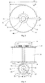
- the impeller 20 is fixedly mounted to the rotary shaft 28 for synchronous rotation with the rotary shaft 28.
- the impeller 20 may be made from plastic material and includes a substrate 160 and a plurality of blades 162 spacedly mounted to the substrate 160 in the circumferential direction.
- the blades 162 of the impeller 20 are arc shaped and include a group of long blades 164 and a group of short blades 166.
- the two groups of blades are alternatively disposed at the outer circumferential edge of the substrate 160 in the circumferential direction.
- a spiral flow passage 168 ( Fig. 11 ) is formed between an inner surface of the pump chamber 12 and the impeller 20.
- a radial cross-sectional area of the flow passage 168 gradually increases in the circumferential direction toward the outlet 18. Under the condition that the rotor has the fixed startup rotating direction, the arc-shaped blades and the spiral flow passage can enhance the hydraulic efficiency.
- a mounting post 170 is disposed at a central area of the substrate 160. One end of the rotary shaft 28 is fixed to the mounting post 170 via a shaft sleeve 172.
- the shaft sleeve 172 may be formed from a metal material.
- the mounting post 170, the shaft sleeve 172 and an injection molding portion 174 which are arranged radially inwardly, cooperatively form a continuous closed end surface.
- the injection molding portion 174 and the mounting post 170 are connected via a bridging portion 176.
- the impeller 20 may utilize straight type blades.
- Fig. 16 illustrates a dishwasher 176 comprising a drain pump according to one embodiment of the present invention.
- the dishwasher includes a cleaning chamber 178, a water supply passage 180 for supplying cleaning water to the cleaning chamber 178, a drain passage 182 for drainage of water, a circulating passage 184 for circulating cleaning water in the cleaning chamber 178, and a control system 188 having a drain pump 10 and a circulating pump 186.
- the drain pump 10 pumps the cleaning water in the cleaning chamber 178 to the drain passage 182, and the circulating pump 186 pumps the cleaning water in the cleaning chamber 178 to the circulating passage 184.
- the motor described in embodiments of the present invention can also be used in other applications.
Claims (10)
- Pompe (10) comprenant :un boîtier de pompe (14) comportant une chambre de pompe (12) ;une entrée (16) et une sortie (18) en communication avec la chambre de pompe (12) ;un moteur (22) comprenant un stator et un rotor (26) pouvant tourner par rapport au stator, le stator comprenant un noyau de stator (54) et des enroulements de stator (56) enroulés autour du noyau de stator (54) et alimentés par une alimentation CA (210) ;une turbine (20) disposée dans la chambre de pompe et connectée de façon fixe à un arbre (28) du rotor (26) de manière à toujours tourner de façon synchrone avec l'arbre ; etune carte de circuit imprimé (82) comportant un circuit de commande qui alimente les enroulements de stator (56) d'une manière prédéterminée pour faire en sorte que les enroulements de stator (56) entraînent le rotor (26) en rotation uniquement dans une direction de démarrage fixe pendant une phase de démarrage du moteur synchrone, le circuit de commande comprenant un commutateur CA bidirectionnel commandable (220), un circuit de conversion CA-CC (230), un capteur de position (158) permettant de détecter la position des pôles magnétiques du rotor (26), et un circuit de commande de commutateur (240) configuré pour commander le commutateur CA bidirectionnel commandable (220) à commuter entre un état de marche et un état d'arrêt de manière prédéfinie, en fonction de la position des pôles magnétiques et des informations de polarité de l'alimentation CA (210) ;caractérisée en ce que le commutateur CA bidirectionnel commandable (220) est connecté en parallèle avec les enroulements de stator (56) et une alimentation CA (210) connectée en série entre deux noeuds (A, B), et en ce que le circuit de conversion CA-CC (230) est connecté en parallèle avec le commutateur CA bidirectionnel commandable (220).
- Pompe selon la revendication 1, dans laquelle le rotor (26) comprend un aimant (30) fixé à l'arbre (28), le rotor (26) présentant la direction de démarrage fixe et tournant à une vitesse constante de 60 f/p (tr/min) à un état stable, chaque fois que le moteur est mis sous tension, f représentant la fréquence de l'alimentation en courant alternatif, et p représentant le nombre de paires de pôles du rotor magnétique permanent.
- Pompe selon la revendication 1 ou 2, dans laquelle la turbine (20) comprend un substrat (160) et une pluralité d'aubes incurvées (162) montées sur le substrat (160) à une certaine distance dans une direction circonférentielle.
- Pompe selon la revendication 1 ou 2, dans laquelle la turbine (20) comprend un substrat (160), et un groupe d'aubes incurvées longues (164) et un groupe d'aubes incurvées courtes (166) montées sur le substrat (160) à une certaine distance dans une direction circonférentielle.
- Pompe selon la revendication 3 ou 4, dans laquelle un montant de fixation (170) est disposé dans une région centrale du substrat (160), une extrémité de l'arbre (28) étant fixée au montant de fixation (170) par l'intermédiaire d'un manchon d'arbre (172), et le montant de fixation (170), le manchon d'arbre (172) et une partie de moulage par injection (174) sur un côté intérieur du manchon d'arbre (172) coopérant pour former une surface d'extrémité fermée continue à une extrémité axiale du montant de fixation (170) à l'opposée du moteur.
- Pompe selon l'une quelconque des revendications précédentes, dans laquelle le boîtier de pompe (14) comprend un corps de couvercle (100) et une plaque de fond (102) montée sur le corps de couvercle (100), et la plaque de fond (102) comprend une paroi inférieure de chambre de pompe (122) comportant une ouverture (120), et un boîtier de rotor (124) s'étendant intégralement axialement et vers l'extérieur à partir de l'ouverture (120).
- Pompe selon la revendication 6, dans laquelle un bouchon d'extrémité (126) est fixé dans une extrémité du boîtier de rotor (124) adjacente à l'ouverture (120), et les extrémités opposées de l'arbre (28) sont respectivement supportées par un premier palier (128) disposé dans le bouchon d'extrémité (126) et par un second palier (130) disposé à une autre extrémité du boîtier de rotor (124) à l'opposé de l'ouverture.
- Pompe selon la revendication 7, dans laquelle le premier palier (128) est monté sur le bouchon d'extrémité (126) par l'intermédiaire d'un amortisseur (132), le premier palier (128) étant de forme cylindrique et comprenant une nervure (134) s'étendant circonférentiellement sur une surface extérieure du premier palier (128), et une surface intérieure de l'amortisseur (132) formant une rainure (136) destinée à venir en prise avec la nervure (134).
- Pompe selon la revendication 7, dans laquelle le second palier (130) est supporté par un siège de palier (138) formé d'un seul tenant avec le boîtier de rotor (124), et une pluralité de dents est formée sur une surface intérieure du siège de palier (138).
- Appareil de nettoyage (176) comprenant une chambre de nettoyage (178), un passage d'alimentation en eau (180) conçu pour fournir de l'eau de nettoyage à la chambre de nettoyage (178), un passage d'évacuation (182) conçu pour évacuer l'eau, et une pompe d'évacuation (10) conçue pour pomper l'eau de nettoyage dans la chambre de nettoyage (178) vers le passage d'évacuation (182), la pompe d'évacuation (10) comprenant les caractéristiques de la pompe selon l'une quelconque des revendications précédentes.
Applications Claiming Priority (2)
| Application Number | Priority Date | Filing Date | Title |
|---|---|---|---|
| CN201410765091 | 2014-12-11 | ||
| CN201510326055 | 2015-06-12 |
Publications (3)
| Publication Number | Publication Date |
|---|---|
| EP3032723A2 EP3032723A2 (fr) | 2016-06-15 |
| EP3032723A3 EP3032723A3 (fr) | 2016-07-13 |
| EP3032723B1 true EP3032723B1 (fr) | 2019-10-02 |
Family
ID=54838235
Family Applications (1)
| Application Number | Title | Priority Date | Filing Date |
|---|---|---|---|
| EP15198537.1A Active EP3032723B1 (fr) | 2014-12-11 | 2015-12-08 | Pompe et appareil de nettoyage |
Country Status (7)
| Country | Link |
|---|---|
| US (1) | US20160169232A1 (fr) |
| EP (1) | EP3032723B1 (fr) |
| JP (1) | JP2016116444A (fr) |
| KR (1) | KR20160071349A (fr) |
| CN (1) | CN105697389A (fr) |
| BR (1) | BR102015030895A2 (fr) |
| MX (1) | MX2015017014A (fr) |
Families Citing this family (7)
| Publication number | Priority date | Publication date | Assignee | Title |
|---|---|---|---|---|
| DE102017206089B4 (de) * | 2017-04-10 | 2020-01-16 | BSH Hausgeräte GmbH | Nassläufer-Pumpe und Haushaltsgerät |
| CN108696057B (zh) * | 2017-04-12 | 2021-06-25 | 德昌电机(深圳)有限公司 | 电机及具有该电机的用电设备 |
| KR102087499B1 (ko) * | 2018-04-30 | 2020-05-27 | 뉴모텍(주) | 세탁기의 배수 펌프 |
| CN108799142A (zh) * | 2018-08-14 | 2018-11-13 | 广东赛普电器制造有限公司 | 一种高效率排水泵 |
| US10634152B2 (en) * | 2018-08-17 | 2020-04-28 | Itt Manufacturing Enterprises Llc | Multi-bearing design for shaft stabilization |
| CN110873060A (zh) * | 2018-08-29 | 2020-03-10 | 广东德昌电机有限公司 | 一种泵体 |
| CN212784960U (zh) * | 2020-06-11 | 2021-03-23 | 博西华电器(江苏)有限公司 | 电机、泵及家用电器 |
Family Cites Families (18)
| Publication number | Priority date | Publication date | Assignee | Title |
|---|---|---|---|---|
| US3009748A (en) * | 1958-07-24 | 1961-11-21 | Roulements A Aiguilles Sa | Accurately centered anti-friction bearing assembly |
| ES2019491A6 (es) * | 1989-08-04 | 1991-06-16 | Fagor S Coop Ltda | Mejoras introducidas en bombas para electrodomesticos accionados por motor sincrono. |
| US5530343A (en) * | 1994-10-07 | 1996-06-25 | Computational Systems, Inc. | Induction motor speed determination by flux spectral analysis |
| US5675226A (en) * | 1995-09-06 | 1997-10-07 | C.E.Set. S.R.L. | Control circuit for an synchronous electric motor of the brushless type |
| US5934298A (en) * | 1997-11-14 | 1999-08-10 | Singh; Baljit | Combination sink and dishwasher |
| CN2705636Y (zh) * | 2004-06-16 | 2005-06-22 | 江门市汉宇电器有限公司 | 一种离心式排水泵 |
| ES2374820T3 (es) * | 2005-08-30 | 2012-02-22 | Askoll Holding S.R.L. | Motor eléctrico síncrono monofásico de imanes permanentes con estructura de estator mejorada, en particular para bombas de descarga de máquinas de lavado y electrodomésticos similares. |
| CN100561855C (zh) * | 2007-11-13 | 2009-11-18 | 广东博宇水族实业有限公司 | 一种采用交流电源驱动永磁电机潜水泵的抽水方法及装置 |
| CN201144830Y (zh) * | 2007-11-14 | 2008-11-05 | 广东博宇水族实业有限公司 | 一种交流永磁同步定向启动潜水泵 |
| ES2391594T3 (es) * | 2008-02-13 | 2012-11-28 | Askoll Holding S.R.L. | Motor eléctrico y electrobomba |
| CN201474995U (zh) * | 2009-07-29 | 2010-05-19 | 浙江利欧股份有限公司 | 一种永磁同步电机水泵 |
| CN101865157A (zh) * | 2010-06-11 | 2010-10-20 | 中国兵器工业集团第七O研究所 | 一种离心式水泵 |
| US8944767B2 (en) * | 2012-01-17 | 2015-02-03 | Hamilton Sundstrand Corporation | Fuel system centrifugal boost pump impeller |
| CN203430799U (zh) * | 2012-06-28 | 2014-02-12 | 德昌电机(深圳)有限公司 | 排水泵及清洗装置 |
| US9263918B2 (en) * | 2012-11-09 | 2016-02-16 | Nidec Motor Corporation | Connection for motor stator segments |
| CN203570667U (zh) * | 2013-09-02 | 2014-04-30 | 浙江同泰泵业有限公司 | 半开式高扬程叶轮 |
| CN203892243U (zh) * | 2014-04-04 | 2014-10-22 | 上海第一水泵厂有限公司 | 用于水煤浆泵的叶轮 |
| CN204877974U (zh) * | 2015-06-12 | 2015-12-16 | 德昌电机(深圳)有限公司 | 泵及清洗装置 |
-
2015
- 2015-11-30 CN CN201510859264.7A patent/CN105697389A/zh not_active Withdrawn
- 2015-12-08 EP EP15198537.1A patent/EP3032723B1/fr active Active
- 2015-12-10 MX MX2015017014A patent/MX2015017014A/es unknown
- 2015-12-10 BR BR102015030895A patent/BR102015030895A2/pt not_active Application Discontinuation
- 2015-12-10 US US14/965,425 patent/US20160169232A1/en not_active Abandoned
- 2015-12-11 KR KR1020150176990A patent/KR20160071349A/ko unknown
- 2015-12-11 JP JP2015241970A patent/JP2016116444A/ja active Pending
Also Published As
| Publication number | Publication date |
|---|---|
| EP3032723A2 (fr) | 2016-06-15 |
| EP3032723A3 (fr) | 2016-07-13 |
| MX2015017014A (es) | 2016-06-10 |
| JP2016116444A (ja) | 2016-06-23 |
| US20160169232A1 (en) | 2016-06-16 |
| KR20160071349A (ko) | 2016-06-21 |
| BR102015030895A2 (pt) | 2016-08-23 |
| CN105697389A (zh) | 2016-06-22 |
Similar Documents
| Publication | Publication Date | Title |
|---|---|---|
| EP3032723B1 (fr) | Pompe et appareil de nettoyage | |
| CN106208582B (zh) | 电机、泵及清洗装置 | |
| EP3032706B1 (fr) | Pompe et appareil de nettoyage | |
| KR20020095348A (ko) | 단상 라인 스타트 영구자석 동기전동기 | |
| US6424114B1 (en) | Synchronous motor | |
| JP2015095997A (ja) | モータ | |
| EP3032722B1 (fr) | Rotor, moteur, pompe et appareil de nettoyage | |
| EP3032721B1 (fr) | Moteur, pompe et appareil de nettoyage | |
| CN105703591B (zh) | 单相电机及使用该单相电机的泵 | |
| EP3032719B1 (fr) | Moteur synchrone, stator de moteur, pompe et appareil de nettoyage | |
| EP3032705B1 (fr) | Moteur, noyau de stator, pompe et appareil de nettoyage | |
| JP2017203458A (ja) | 真空ポンプ及び電動モーター |
Legal Events
| Date | Code | Title | Description |
|---|---|---|---|
| PUAI | Public reference made under article 153(3) epc to a published international application that has entered the european phase |
Free format text: ORIGINAL CODE: 0009012 |
|
| PUAL | Search report despatched |
Free format text: ORIGINAL CODE: 0009013 |
|
| AK | Designated contracting states |
Kind code of ref document: A2 Designated state(s): AL AT BE BG CH CY CZ DE DK EE ES FI FR GB GR HR HU IE IS IT LI LT LU LV MC MK MT NL NO PL PT RO RS SE SI SK SM TR |
|
| AX | Request for extension of the european patent |
Extension state: BA ME |
|
| AK | Designated contracting states |
Kind code of ref document: A3 Designated state(s): AL AT BE BG CH CY CZ DE DK EE ES FI FR GB GR HR HU IE IS IT LI LT LU LV MC MK MT NL NO PL PT RO RS SE SI SK SM TR |
|
| AX | Request for extension of the european patent |
Extension state: BA ME |
|
| RIC1 | Information provided on ipc code assigned before grant |
Ipc: F04D 13/06 20060101ALI20160603BHEP Ipc: H02K 29/03 20060101AFI20160603BHEP |
|
| STAA | Information on the status of an ep patent application or granted ep patent |
Free format text: STATUS: REQUEST FOR EXAMINATION WAS MADE |
|
| 17P | Request for examination filed |
Effective date: 20170109 |
|
| RBV | Designated contracting states (corrected) |
Designated state(s): AL AT BE BG CH CY CZ DE DK EE ES FI FR GB GR HR HU IE IS IT LI LT LU LV MC MK MT NL NO PL PT RO RS SE SI SK SM TR |
|
| GRAP | Despatch of communication of intention to grant a patent |
Free format text: ORIGINAL CODE: EPIDOSNIGR1 |
|
| STAA | Information on the status of an ep patent application or granted ep patent |
Free format text: STATUS: GRANT OF PATENT IS INTENDED |
|
| INTG | Intention to grant announced |
Effective date: 20190503 |
|
| RAP1 | Party data changed (applicant data changed or rights of an application transferred) |
Owner name: JOHNSON ELECTRIC INTERNATIONAL AG |
|
| GRAS | Grant fee paid |
Free format text: ORIGINAL CODE: EPIDOSNIGR3 |
|
| GRAA | (expected) grant |
Free format text: ORIGINAL CODE: 0009210 |
|
| STAA | Information on the status of an ep patent application or granted ep patent |
Free format text: STATUS: THE PATENT HAS BEEN GRANTED |
|
| AK | Designated contracting states |
Kind code of ref document: B1 Designated state(s): AL AT BE BG CH CY CZ DE DK EE ES FI FR GB GR HR HU IE IS IT LI LT LU LV MC MK MT NL NO PL PT RO RS SE SI SK SM TR |
|
| REG | Reference to a national code |
Ref country code: GB Ref legal event code: FG4D |
|
| REG | Reference to a national code |
Ref country code: CH Ref legal event code: EP Ref country code: AT Ref legal event code: REF Ref document number: 1187303 Country of ref document: AT Kind code of ref document: T Effective date: 20191015 |
|
| REG | Reference to a national code |
Ref country code: DE Ref legal event code: R096 Ref document number: 602015038981 Country of ref document: DE |
|
| REG | Reference to a national code |
Ref country code: IE Ref legal event code: FG4D |
|
| REG | Reference to a national code |
Ref country code: NL Ref legal event code: MP Effective date: 20191002 |
|
| REG | Reference to a national code |
Ref country code: LT Ref legal event code: MG4D |
|
| REG | Reference to a national code |
Ref country code: AT Ref legal event code: MK05 Ref document number: 1187303 Country of ref document: AT Kind code of ref document: T Effective date: 20191002 |
|
| PG25 | Lapsed in a contracting state [announced via postgrant information from national office to epo] |
Ref country code: GR Free format text: LAPSE BECAUSE OF FAILURE TO SUBMIT A TRANSLATION OF THE DESCRIPTION OR TO PAY THE FEE WITHIN THE PRESCRIBED TIME-LIMIT Effective date: 20200103 Ref country code: ES Free format text: LAPSE BECAUSE OF FAILURE TO SUBMIT A TRANSLATION OF THE DESCRIPTION OR TO PAY THE FEE WITHIN THE PRESCRIBED TIME-LIMIT Effective date: 20191002 Ref country code: PL Free format text: LAPSE BECAUSE OF FAILURE TO SUBMIT A TRANSLATION OF THE DESCRIPTION OR TO PAY THE FEE WITHIN THE PRESCRIBED TIME-LIMIT Effective date: 20191002 Ref country code: LT Free format text: LAPSE BECAUSE OF FAILURE TO SUBMIT A TRANSLATION OF THE DESCRIPTION OR TO PAY THE FEE WITHIN THE PRESCRIBED TIME-LIMIT Effective date: 20191002 Ref country code: NO Free format text: LAPSE BECAUSE OF FAILURE TO SUBMIT A TRANSLATION OF THE DESCRIPTION OR TO PAY THE FEE WITHIN THE PRESCRIBED TIME-LIMIT Effective date: 20200102 Ref country code: NL Free format text: LAPSE BECAUSE OF FAILURE TO SUBMIT A TRANSLATION OF THE DESCRIPTION OR TO PAY THE FEE WITHIN THE PRESCRIBED TIME-LIMIT Effective date: 20191002 Ref country code: SE Free format text: LAPSE BECAUSE OF FAILURE TO SUBMIT A TRANSLATION OF THE DESCRIPTION OR TO PAY THE FEE WITHIN THE PRESCRIBED TIME-LIMIT Effective date: 20191002 Ref country code: LV Free format text: LAPSE BECAUSE OF FAILURE TO SUBMIT A TRANSLATION OF THE DESCRIPTION OR TO PAY THE FEE WITHIN THE PRESCRIBED TIME-LIMIT Effective date: 20191002 Ref country code: PT Free format text: LAPSE BECAUSE OF FAILURE TO SUBMIT A TRANSLATION OF THE DESCRIPTION OR TO PAY THE FEE WITHIN THE PRESCRIBED TIME-LIMIT Effective date: 20200203 Ref country code: FI Free format text: LAPSE BECAUSE OF FAILURE TO SUBMIT A TRANSLATION OF THE DESCRIPTION OR TO PAY THE FEE WITHIN THE PRESCRIBED TIME-LIMIT Effective date: 20191002 Ref country code: AT Free format text: LAPSE BECAUSE OF FAILURE TO SUBMIT A TRANSLATION OF THE DESCRIPTION OR TO PAY THE FEE WITHIN THE PRESCRIBED TIME-LIMIT Effective date: 20191002 Ref country code: BG Free format text: LAPSE BECAUSE OF FAILURE TO SUBMIT A TRANSLATION OF THE DESCRIPTION OR TO PAY THE FEE WITHIN THE PRESCRIBED TIME-LIMIT Effective date: 20200102 |
|
| PG25 | Lapsed in a contracting state [announced via postgrant information from national office to epo] |
Ref country code: CZ Free format text: LAPSE BECAUSE OF FAILURE TO SUBMIT A TRANSLATION OF THE DESCRIPTION OR TO PAY THE FEE WITHIN THE PRESCRIBED TIME-LIMIT Effective date: 20191002 Ref country code: RS Free format text: LAPSE BECAUSE OF FAILURE TO SUBMIT A TRANSLATION OF THE DESCRIPTION OR TO PAY THE FEE WITHIN THE PRESCRIBED TIME-LIMIT Effective date: 20191002 Ref country code: IS Free format text: LAPSE BECAUSE OF FAILURE TO SUBMIT A TRANSLATION OF THE DESCRIPTION OR TO PAY THE FEE WITHIN THE PRESCRIBED TIME-LIMIT Effective date: 20200224 Ref country code: HR Free format text: LAPSE BECAUSE OF FAILURE TO SUBMIT A TRANSLATION OF THE DESCRIPTION OR TO PAY THE FEE WITHIN THE PRESCRIBED TIME-LIMIT Effective date: 20191002 |
|
| PG25 | Lapsed in a contracting state [announced via postgrant information from national office to epo] |
Ref country code: AL Free format text: LAPSE BECAUSE OF FAILURE TO SUBMIT A TRANSLATION OF THE DESCRIPTION OR TO PAY THE FEE WITHIN THE PRESCRIBED TIME-LIMIT Effective date: 20191002 |
|
| REG | Reference to a national code |
Ref country code: DE Ref legal event code: R097 Ref document number: 602015038981 Country of ref document: DE |
|
| PG2D | Information on lapse in contracting state deleted |
Ref country code: IS |
|
| PG25 | Lapsed in a contracting state [announced via postgrant information from national office to epo] |
Ref country code: EE Free format text: LAPSE BECAUSE OF FAILURE TO SUBMIT A TRANSLATION OF THE DESCRIPTION OR TO PAY THE FEE WITHIN THE PRESCRIBED TIME-LIMIT Effective date: 20191002 Ref country code: DK Free format text: LAPSE BECAUSE OF FAILURE TO SUBMIT A TRANSLATION OF THE DESCRIPTION OR TO PAY THE FEE WITHIN THE PRESCRIBED TIME-LIMIT Effective date: 20191002 Ref country code: RO Free format text: LAPSE BECAUSE OF FAILURE TO SUBMIT A TRANSLATION OF THE DESCRIPTION OR TO PAY THE FEE WITHIN THE PRESCRIBED TIME-LIMIT Effective date: 20191002 Ref country code: IS Free format text: LAPSE BECAUSE OF FAILURE TO SUBMIT A TRANSLATION OF THE DESCRIPTION OR TO PAY THE FEE WITHIN THE PRESCRIBED TIME-LIMIT Effective date: 20200202 |
|
| REG | Reference to a national code |
Ref country code: CH Ref legal event code: PL |
|
| PLBE | No opposition filed within time limit |
Free format text: ORIGINAL CODE: 0009261 |
|
| STAA | Information on the status of an ep patent application or granted ep patent |
Free format text: STATUS: NO OPPOSITION FILED WITHIN TIME LIMIT |
|
| REG | Reference to a national code |
Ref country code: BE Ref legal event code: MM Effective date: 20191231 |
|
| PG25 | Lapsed in a contracting state [announced via postgrant information from national office to epo] |
Ref country code: SM Free format text: LAPSE BECAUSE OF FAILURE TO SUBMIT A TRANSLATION OF THE DESCRIPTION OR TO PAY THE FEE WITHIN THE PRESCRIBED TIME-LIMIT Effective date: 20191002 Ref country code: MC Free format text: LAPSE BECAUSE OF FAILURE TO SUBMIT A TRANSLATION OF THE DESCRIPTION OR TO PAY THE FEE WITHIN THE PRESCRIBED TIME-LIMIT Effective date: 20191002 Ref country code: SK Free format text: LAPSE BECAUSE OF FAILURE TO SUBMIT A TRANSLATION OF THE DESCRIPTION OR TO PAY THE FEE WITHIN THE PRESCRIBED TIME-LIMIT Effective date: 20191002 |
|
| 26N | No opposition filed |
Effective date: 20200703 |
|
| PG25 | Lapsed in a contracting state [announced via postgrant information from national office to epo] |
Ref country code: LU Free format text: LAPSE BECAUSE OF NON-PAYMENT OF DUE FEES Effective date: 20191208 Ref country code: IE Free format text: LAPSE BECAUSE OF NON-PAYMENT OF DUE FEES Effective date: 20191208 |
|
| PG25 | Lapsed in a contracting state [announced via postgrant information from national office to epo] |
Ref country code: SI Free format text: LAPSE BECAUSE OF FAILURE TO SUBMIT A TRANSLATION OF THE DESCRIPTION OR TO PAY THE FEE WITHIN THE PRESCRIBED TIME-LIMIT Effective date: 20191002 Ref country code: LI Free format text: LAPSE BECAUSE OF NON-PAYMENT OF DUE FEES Effective date: 20191231 Ref country code: CH Free format text: LAPSE BECAUSE OF NON-PAYMENT OF DUE FEES Effective date: 20191231 Ref country code: BE Free format text: LAPSE BECAUSE OF NON-PAYMENT OF DUE FEES Effective date: 20191231 |
|
| PG25 | Lapsed in a contracting state [announced via postgrant information from national office to epo] |
Ref country code: CY Free format text: LAPSE BECAUSE OF FAILURE TO SUBMIT A TRANSLATION OF THE DESCRIPTION OR TO PAY THE FEE WITHIN THE PRESCRIBED TIME-LIMIT Effective date: 20191002 |
|
| PG25 | Lapsed in a contracting state [announced via postgrant information from national office to epo] |
Ref country code: MT Free format text: LAPSE BECAUSE OF FAILURE TO SUBMIT A TRANSLATION OF THE DESCRIPTION OR TO PAY THE FEE WITHIN THE PRESCRIBED TIME-LIMIT Effective date: 20191002 Ref country code: HU Free format text: LAPSE BECAUSE OF FAILURE TO SUBMIT A TRANSLATION OF THE DESCRIPTION OR TO PAY THE FEE WITHIN THE PRESCRIBED TIME-LIMIT; INVALID AB INITIO Effective date: 20151208 |
|
| PGFP | Annual fee paid to national office [announced via postgrant information from national office to epo] |
Ref country code: FR Payment date: 20211109 Year of fee payment: 7 Ref country code: TR Payment date: 20211208 Year of fee payment: 7 Ref country code: GB Payment date: 20211014 Year of fee payment: 7 Ref country code: DE Payment date: 20211012 Year of fee payment: 7 |
|
| PGFP | Annual fee paid to national office [announced via postgrant information from national office to epo] |
Ref country code: IT Payment date: 20211110 Year of fee payment: 7 |
|
| PG25 | Lapsed in a contracting state [announced via postgrant information from national office to epo] |
Ref country code: MK Free format text: LAPSE BECAUSE OF FAILURE TO SUBMIT A TRANSLATION OF THE DESCRIPTION OR TO PAY THE FEE WITHIN THE PRESCRIBED TIME-LIMIT Effective date: 20191002 |
|
| REG | Reference to a national code |
Ref country code: DE Ref legal event code: R119 Ref document number: 602015038981 Country of ref document: DE |
|
| GBPC | Gb: european patent ceased through non-payment of renewal fee |
Effective date: 20221208 |
|
| PG25 | Lapsed in a contracting state [announced via postgrant information from national office to epo] |
Ref country code: GB Free format text: LAPSE BECAUSE OF NON-PAYMENT OF DUE FEES Effective date: 20221208 Ref country code: DE Free format text: LAPSE BECAUSE OF NON-PAYMENT OF DUE FEES Effective date: 20230701 |
|
| PG25 | Lapsed in a contracting state [announced via postgrant information from national office to epo] |
Ref country code: FR Free format text: LAPSE BECAUSE OF NON-PAYMENT OF DUE FEES Effective date: 20221231 |
|
| PG25 | Lapsed in a contracting state [announced via postgrant information from national office to epo] |
Ref country code: IT Free format text: LAPSE BECAUSE OF NON-PAYMENT OF DUE FEES Effective date: 20221208 |