EP3032230A2 - Débitmètre et procédé d'étalonnage - Google Patents
Débitmètre et procédé d'étalonnage Download PDFInfo
- Publication number
- EP3032230A2 EP3032230A2 EP15197857.4A EP15197857A EP3032230A2 EP 3032230 A2 EP3032230 A2 EP 3032230A2 EP 15197857 A EP15197857 A EP 15197857A EP 3032230 A2 EP3032230 A2 EP 3032230A2
- Authority
- EP
- European Patent Office
- Prior art keywords
- flow rate
- fluid
- calibration relationship
- sensor
- output signal
- Prior art date
- Legal status (The legal status is an assumption and is not a legal conclusion. Google has not performed a legal analysis and makes no representation as to the accuracy of the status listed.)
- Granted
Links
- 238000000034 method Methods 0.000 title claims description 29
- 239000012530 fluid Substances 0.000 claims abstract description 170
- 238000005259 measurement Methods 0.000 claims abstract description 92
- 238000012545 processing Methods 0.000 claims abstract description 40
- 239000000203 mixture Substances 0.000 claims description 18
- 238000011065 in-situ storage Methods 0.000 claims description 4
- VNWKTOKETHGBQD-UHFFFAOYSA-N methane Chemical compound C VNWKTOKETHGBQD-UHFFFAOYSA-N 0.000 description 28
- 230000006870 function Effects 0.000 description 17
- 239000003345 natural gas Substances 0.000 description 9
- OTMSDBZUPAUEDD-UHFFFAOYSA-N Ethane Chemical compound CC OTMSDBZUPAUEDD-UHFFFAOYSA-N 0.000 description 5
- 239000007789 gas Substances 0.000 description 5
- ATUOYWHBWRKTHZ-UHFFFAOYSA-N Propane Chemical compound CCC ATUOYWHBWRKTHZ-UHFFFAOYSA-N 0.000 description 4
- 230000007246 mechanism Effects 0.000 description 4
- 238000011144 upstream manufacturing Methods 0.000 description 4
- 238000013507 mapping Methods 0.000 description 2
- 238000012986 modification Methods 0.000 description 2
- 230000004048 modification Effects 0.000 description 2
- 239000001294 propane Substances 0.000 description 2
- 230000002411 adverse Effects 0.000 description 1
- 239000001273 butane Substances 0.000 description 1
- 230000008859 change Effects 0.000 description 1
- 238000007620 mathematical function Methods 0.000 description 1
- IJDNQMDRQITEOD-UHFFFAOYSA-N n-butane Chemical compound CCCC IJDNQMDRQITEOD-UHFFFAOYSA-N 0.000 description 1
- OFBQJSOFQDEBGM-UHFFFAOYSA-N n-pentane Natural products CCCCC OFBQJSOFQDEBGM-UHFFFAOYSA-N 0.000 description 1
- 230000003287 optical effect Effects 0.000 description 1
- 230000008569 process Effects 0.000 description 1
- 238000003860 storage Methods 0.000 description 1
- 238000012546 transfer Methods 0.000 description 1
Images


Classifications
-
- G—PHYSICS
- G01—MEASURING; TESTING
- G01F—MEASURING VOLUME, VOLUME FLOW, MASS FLOW OR LIQUID LEVEL; METERING BY VOLUME
- G01F25/00—Testing or calibration of apparatus for measuring volume, volume flow or liquid level or for metering by volume
- G01F25/10—Testing or calibration of apparatus for measuring volume, volume flow or liquid level or for metering by volume of flowmeters
- G01F25/17—Testing or calibration of apparatus for measuring volume, volume flow or liquid level or for metering by volume of flowmeters using calibrated reservoirs
Definitions
- flow-meters may provide a mass flow rate measurement (e.g., kilogram/second) of a fluid.
- Other flow meters may include vortex-based sensing where, for example, the frequency at which the vortices are formed (shed) is essentially proportional to the volumetric flow rate of the fluid.
- Mass flow meters typically generate mass flow rate of a fluid, and do not provide a direct volumetric flow rate measurement, and therefore volumetric flow rate may be derived by dividing the mass flow rate by density of the fluid. Consequently, such mass flow-meters, when used for volumetric flow rate measurements, may be adversely affected when a condition of the fluid is uncertain or changes in the field.
- the condition of the fluid for example may include unknown gas density fluctuations, temperature fluctuations, gas mixture composition change, etc.
- vortex-based flow meters may provide a direct volumetric flow rate measurement which is insensitive or less sensitive to certain conditions of the fluid, such as density or composition changes.
- vortex based flow meters are often bounded by a lower flow rate measurement limit, below which the fluid velocity is too low or inadequate to form vortices, making vortex based flow rate measurement infeasible.
- a fluid may be characterized by a condition that represents a combination of one or more properties of the fluid.
- the properties may include a composition of a fluid, a density of the fluid, a temperature of the fluid, a pressure of the fluid, or combinations thereof.
- the natural gas may have different compositions, such as, different proportions of methane, ethane, propane, butane, etc.
- mass flow meters known in the art, are factory calibrated based on determined conditions, such as composition, density, temperature, and pressure, of fluid.
- flow meters (such as the mass flow meters) known in the art are factory calibrated for a determined composition or density of natural gas at standard temperature and pressure.
- a system in accordance with one embodiment, includes a first sensor that generates a first output signal representative of a first flow rate measurement in a first flow rate range of a fluid, a second sensor that generates a second output signal representative of a second flow rate measurement in a second flow rate range of the fluid that at least partially overlaps the first flow rate range of the fluid to form a partially overlapping region, a data repository storing a first calibration relationship corresponding to a first condition of the fluid and a second calibration relationship corresponding to a second condition of the fluid, a processing subsystem that automatically generates a third calibration relationship when the second flow rate measurement falls in the partially overlapping region, wherein the third calibration relationship corresponds to a third condition of the fluid based at least on the first calibration relationship and the second calibration relationship, wherein the first sensor is sensitive to variations in condition of the fluid and the second sensor is insensitive or less sensitive to variations in condition of the fluid.
- a method for in-situ flow rate determination of a fluid in a flow meter includes generating by a first sensor in the flow-meter, a first output signal representative of a first flow rate measurement in a first flow rate range of the fluid, generating by a second sensor in the flow-meter, a second output signal representative of a second flow rate measurement in a second flow rate range that at least partially overlaps the first flow rate range of the fluid, receiving from a data repository , a first calibration relationship corresponding to a first condition of the fluid and a second calibration relationship corresponding to a second condition of the fluid, automatically generating a third calibration relationship corresponding to a third condition of the fluid based at least on the first calibration relationship, the second calibration relationship, and determining a third flow rate corresponding to the third condition of the fluid based on the third calibration relationship and the first output signal or the second output signal.
- processing subsystem may include either a single component or a plurality of components, which are either active and/or passive and are connected or otherwise coupled together to provide the described function or functions.
- processing subsystem may include a digital signal processor, a microprocessor, a microcomputer, a microcontroller, and/or any other suitable device.
- a 'sensor' may include one or more physical and individual sensing devices/chips, and/or may include a single sensing device/chip comprising two or more sensing mechanisms.
- a 'sensor' may include a single sensing device/chip that includes two sensing mechanisms wherein one sensing mechanism is capable of measuring volumetric measurements, and another sensing mechanism is capable of measuring mass flow rate measurements.
- Flow meters known in the art may not determine accurate flow rates of a fluid due to on-field varying conditions of the fluid.
- the varying conditions of the fluid for example may include a variation in at least one or more of the composition of the fluid, the density of the fluid, the temperature of the fluid, the pressure of the fluid, the humidity of the fluid, or combinations thereof.
- existing thermal mass flow meters may not be able to determine accurate volumetric flow rate due to variations in the composition or density of the natural gas.
- the present systems and techniques present an on-field calibration method and system.
- the present systems and techniques determine whether self-calibration of a flow meter is required, and the flow meter automatically self-calibrates when required.
- the term "automatically/automatic” refers to performance of a task without manual intervention or manual control, and is performed by a processing subsystem programmed to perform the task.
- the present systems and techniques determine substantially accurate flow rates for varying conditions of fluid across a wide flow rate range.
- the present systems provide a flow meter that includes at least two sensors including a first sensor and a second sensor.
- Each of the first sensor and the second sensor operates in a respective flow rate range.
- the first sensor operates in a first flow rate range and the second sensor operates in a second flow rate range.
- the first flow rate range and the second flow rate range partially overlap.
- the first sensor may be sensitive to fluid condition variations and therefore requires different calibration relationships for different conditions of the fluid.
- the second sensor may be insensitive or less sensitive to fluid conditions, and therefore despite variations in fluid conditions the second sensor measures substantially accurate flow rate of the fluid.
- the second sensor does not operate at low flow rates of the fluid, and hence the second sensor cannot be used for measuring low flow rates.
- the first sensor is factory calibrated in the first flow rate range for pre-determined conditions of the fluid.
- the second sensor is insensitive or less sensitive to any fluid condition
- the second sensor is factory calibrated in the second flow rate range, and unlike the calibrations of the first sensor, the factory calibration of the second sensor is not related to a condition of the fluid.
- the flow meter automatically self-calibrates the first sensor when the condition of the fluid being metered differs from pre-determined conditions of pre-determined calibrations.
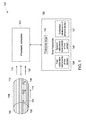
- FIG. 1 illustrates schematically a flow-meter system 100 that is capable of determining whether a new calibration is required, and that automatically self-calibrates when the new calibration is required, in accordance with one embodiment.
- the flow-meter system 100 further determines a flow rate of a fluid 102 based on the new calibration.
- the fluid 102 for example may be characterized by different conditions.
- the fluid 102 is natural gas
- the natural gas may have different compositions, such as, different proportions of methane, ethane, propane, etc.
- the fluid 102 may be characterized by a first condition, a second condition and a third condition.
- the fluid 102 is described to be characterized by three conditions, the fluid 102 nonetheless may be characterized by more or less than three conditions.
- the first condition, the second condition and the third condition are different with respect to each other due to a variation in one or more properties of the fluid 102, such as a composition of the fluid 102, a density of the fluid 102, a temperature of the fluid 102, humidity of the fluid 102, or combinations thereof.
- the system 100 includes at least one pair of sensors 104, 106 and at least one conduit 108.
- Each of the sensors 104, 106 is positioned within the conduit 108.
- the conduit 108 has an upstream opening 110 and a downstream opening 112 that allows the fluid 102 to pass through the conduit 108.
- the fluid 102 enters the conduit 108 from the upstream opening 110 and leaves the conduit 108 from the downstream opening 112.
- upstream and downstream are relative terms that are related to the direction of fluid 102 passing through the conduit 108.
- element 112 would be the upstream opening and element 110 would be the downstream opening.
- the sensors 104, 106 are mounted on a printed circuit board (PCB) 114.
- PCB printed circuit board
- first sensor 104 and the second sensor 106 may be a sensing device, a transducer, a digital sensor, or the like.
- the first sensor 104 for example may include a thermopile sensor, a pressure sensor, or the like.
- the first sensor 104 is a thermal-based mass flow rate sensor.
- the second sensor 106 for example may be a vortex-based sensor, an ultrasonic sensor, or the like.
- the second sensor 106 may be a volumetric flow sensor.
- the first sensor 104 is sensitive to a first flow rate range and the second sensor 106 is sensitive to a second flow rate range of the fluid 102, such that the first flow rate range and the second flow rate range partially overlap in a partially overlapping region.
- the term "partially overlapping region" is used to refer to a flow rate range of the fluid 102 that can be sensed and/or measured by both the first sensor 104 and the second sensor 106.
- the first sensor 104 may be sensitive to the varying fluid conditions and the second sensor 106 may be insensitive or less sensitive to the varying fluid conditions in their respective flow rate ranges including the first flow rate range and the second flow rate range.
- the first flow rate range may include a flow rate of about 0.1 liters/minute to about 20 liters/minute.
- the second flow rate range may include a flow rate of about 5 liters/minute to about 50 liters/minute.
- the second sensor 106 may not operate in a flow rate range below 5 liters per minute.
- the first sensor 104 and the second sensor 106 both operate in the partially overlapping region of about 5 liters/minute to about 20 liters/minute.
- the first flow rate range includes a first non-overlapping range of about 0.1 liters/minute to about 5 liters/minute and a partially overlapping range of about 5 liters/minute to about 20 liters/minute.
- the second flow rate range may include a second non-overlapping flow rate range of about 20 liters/minute to about 50 liters/minute, and the partially overlapping range of about 5 liters/minute to about 20 liters/minute.
- the first sensor 104 and the second sensor 106 sense one or more characteristics of the fluid 102 to simultaneously generate a first output signal 116 and a second output signal 118, respectively.
- the characteristics may include a temperature drop or pressure drop along the flow path of the fluid 102, the frequency of vortices formed in the fluid 102, or the like.
- the first output signal 116 and the second output signal 118 may be electrical signals, such as, voltage or current signals.
- the first output signal 116 is representative of a first flow rate measurement of the fluid 102 measured by the first sensor 104
- the second output signal 118 is representative of a second flow rate measurement of the fluid 102 measured by the second sensor 106.
- first output signal 116 and the second output signal 118 are referred to in the singular form, each may represent more than one signal.
- the first flow rate measurement falls in the first flow rate range of the first sensor 104
- the second flow rate measurement falls in the second flow rate range of the second sensor106.
- the first sensor104 is factory calibrated to map potential outputs of the first sensor104 to respective flow rates for different flow rates of the fluid 102.
- the first sensor 104 is factory calibrated for a first condition of the fluid 102 and a second condition of the fluid 102.
- the first sensor 104 may be factory calibrated to generate a first calibration relationship 124 and a second calibration relationship 126.
- the first calibration relationship 124 may be a table or a function that defines a relationship between the potential outputs of the first sensor 104 to corresponding flow rates of the fluid 102 characterized under the first condition.
- the second calibration relationship 126 may be a table or a function that defines a relationship between outputs of the first sensor 104 to corresponding flow rates of the fluid 102 characterized under the second condition. It is noted that while in the presently contemplated configuration, the first calibration relationship 124 and the second calibration relationship 126 are generated in factory, in certain embodiments, the first calibration relationship 124 and the second calibration relationship 126 may be generated in field during automated or manual in-situ self-calibration of the system 100 using a process explained further herein.
- the second sensor 106 may be factory calibrated to generate a calibration relationship 127, which may be a table or a function that defines a relationship between the potential outputs of the second sensor 106 to corresponding flow rates of the fluid 102 in the second flow rate range.
- a calibration relationship 127 may be a table or a function that defines a relationship between the potential outputs of the second sensor 106 to corresponding flow rates of the fluid 102 in the second flow rate range.
- the system 100 further includes a data repository 122 that stores the first calibration relationship 124 of the first sensor 104 corresponding to the first condition of the fluid 102. Furthermore, the data repository 122 stores the second calibration relationships 126 of the first sensor 104 corresponding to the second condition of the fluid 102. The data repository 122 may store a pre-determined tolerance range 128 that may be accessed by the processing subsystem 120 in determining whether the new calibration is required. Additionally, the data repository 122 stores the calibration relationship 127 of the second sensor 106.
- the system 100 further includes a processing subsystem 120 that receives the first output signal 116 and the second output signal 118 from the first sensor 104 and the second sensor 106, respectively.
- the processing subsystem 120 is programmed to determine the first flow rate measurement and the second flow rate measurement based on the first output signal 116 and the second output signal 118, respectively. Furthermore, the processing subsystem 120 compares the first flow rate measurement measured by the first sensor 104 and the second flow rate measurement measured by the second sensor 106 to determine whether the new calibration is required. When the first flow rate measurement and the second flow rate measurement are substantially similar, then the processing subsystem 120 determines that the new calibration is not required, whereas when the first flow rate measurement and the second flow rate measurement are not substantially similar, then the processing subsystem 120 determines that the new calibration is required.
- the first flow rate measurement and the second flow rate measurement are identified as not being substantially similar when a difference between the first flow rate measurement and the second flow rate measurement is beyond the pre-determined tolerance range 128 stored in the data repository 122.
- the pre-determined tolerance range may be of about -0.5% to about +0.5% of the second flow rate measurement. The determination as to whether the new calibration is required is explained in greater detail with reference to Fig. 2 . Furthermore, the processing subsystem 120 determines whether the second flow rate measurement falls in the partially overlapping region.
- the processing subsystem 120 determines that the second flow rate measurement falls in the partially overlapping region and a new calibration is required, then the processing subsystem 120 receives the first calibration relationship 124 and the second calibration relationship 126 of the first sensor 104 from the data repository 122. Subsequently, the processing subsystem 120 automatically generates a third calibration relationship corresponding to the third condition of the fluid 102 based at least on the first calibration relationship 124, the second calibration relationship 126, the first output signal 116 and the second output signal 118. In one embodiment, the processing subsystem 120 automatically generates the third calibration relationship by applying a linear interpolation technique using at least one of the first calibration relationship 124, and the second calibration relationship 126.
- the third calibration relationship for example may be a table or a function that defines a relationship between outputs of the first sensor 104 to corresponding flow rates of the fluid 102 characterized by the third condition.
- the three conditions of the fluid 102 may be three different compositions of the natural gas.
- the automatic generation of the third calibration relationship is explained in greater detail with reference to Fig. 2 and Fig. 3 .
- the processing subsystem 120 further determines a third flow rate corresponding to the third condition of the fluid 102 based on the third calibration relationship and the first output signal 116.
- the processing subsystem 120 determines the third flow rate by mapping the first output signal 116 to the corresponding third flow rate when the third calibration relationship is a table.
- the processing subsystem 120 determines the third flow rate by substituting a value of the first output signal in the third calibration relationship when the third calibration relationship is a mathematical function (for example a transfer function).
- the foregoing examples, demonstrations, and process steps such as those that may be performed by the processing subsystem 120 may be implemented by suitable code on a processor-based system, such as a general-purpose or special-purpose computer. It should also be noted that different implementations of the present technique may perform some or all of the steps described herein in different orders or substantially concurrently, that is, in parallel. Furthermore, the functions may be implemented in a variety of programming languages, including but not limited to assembly language, C, C++, Python, or Java.
- Such code may be stored or adapted for storage on one or more tangible, machine readable media, such as on data repository chips, local or remote hard disks, optical disks (that is, CDs, DVDs, or the like), or other media, which may be accessed by a processor-based system to execute the stored code.
- tangible, machine readable media such as on data repository chips, local or remote hard disks, optical disks (that is, CDs, DVDs, or the like), or other media, which may be accessed by a processor-based system to execute the stored code.
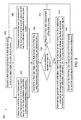
- Fig. 2 is a flow chart illustrating a method 200 to self-calibrate a flow meter and determine a flow rate of the fluid 102 referred to in Fig. 1 , in accordance with one embodiment.
- the first output signal 116 measured by the first sensor 104 and the second output signal 118 measured by the second sensor 106 are received.
- the first sensor may be sensitive to fluid condition variation (therefore results in substantially inaccurate flow rate measurements with fluid condition variations) and operates in the first flow rate range of the fluid 102
- the second sensor 106 may be insensitive or less sensitive to fluid condition variation (therefore results in substantially accurate flow rate measurements irrespective of fluid condition variations) and operates in the second flow rate range of the fluid 102.
- the first flow rate range and the second flow rate range may overlap in a partially overlapping region, and therefore the first flow rate measurement and the second flow rate measurement may together fall in the partially overlapping region.
- the first flow rate range starts at about 0.1 liters per minute and ends at about 20 liters per minute
- the second flow rate range starts at about 5 liters per minute and ends at about 50 liters per minute
- the first flow rate range and the second flow rate range overlap in a partially overlapping region starting at about 5 liters per minute and ending at about 20 liters per minute.
- the first output signal 116 and the second output signal 118 may be received by the processing subsystem 122 referred to in Fig. 1 .
- a first flow rate measurement may be determined based on the first output signal 116 and the first calibration relationship 124 or the second calibration relationship 126 of the first sensor 104, and at block 206 a second flow rate measurement may be determined based on the second output signal 118 and the calibration relationship 127 of the second sensor 106.
- a flow rate range of the fluid 102 may be determined based on the first flow rate measurement measured by first sensor 104 and the second flow rate measurement measured by the second sensor 106.
- the flow rate range of the fluid may include the first non-overlapping flow rate range of the first sensor 104, the second non-overlapping flow rate range of the second sensor 106, or the partially overlapping region of the first sensor 104 and the second sensor 106 referred to in Fig. 1 .
- a check is carried out to determine whether a new calibration of the first sensor 104 is required. The requirement of the new calibration is determined based on the first flow rate measurement 204 and the second flow rate measurement 206. The determination of the requirement of the new calibration is explained in greater detail with reference to Fig. 5 . When it is determined that the new calibration of the first sensor 104 is not required, the control is transferred to block 212.
- the first flow rate measurement or the second flow rate measurement is reported out to a user based on the flow rate range. For example, when the flow rate range is determined to be the first non-overlapping flow rate range of the first sensor 104, then the first flow rate measurement measured by the first sensor 104 is reported out as a flow rate of the fluid 102 to the user. Similarly, when the flow rate range is determined to be the second non-overlapping flow rate range, then the second flow rate measurement measured by the second sensor 106 is reported out as the flow rate of the fluid 102 to the user. Furthermore, when the flow rate range is determined to be the partially overlapping range, then the second flow rate measurement measured by the second sensor 102 is reported out as the flow rate of the fluid 102 to the user.
- a third calibration relationship corresponding to the third condition of the fluid is automatically generated based on the first calibration relationship 124, the second calibration relationship of the first sensor 104 (see Fig. 1 ), the first output signal 116 and the second output signal 118.
- the third calibration relationship is generated by applying a linear interpolation technique at least on the first calibration relationship 124 and the second calibration relationship 126.
- the third calibration relationship for example may be a table or a function that defines a relationship between various outputs of the first sensor 104 (see Fig.
- the third calibration relationship is saved in the data repository 122 (see Fig. 1 ) as a current calibration relationship for the first sensor 104.
- a third flow rate of the fluid 102 is determined based on the first output signal 116 and the third calibration relationship.
- the third flow rate is determined by substituting a value of the first output signal 116 into the function.
- the third flow rate is determined by mapping a value of the first output signal 116 to the corresponding third flow rate.
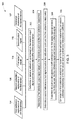
- Fig. 3 is a flow chart illustrating a method 300 to automatically generate the third calibration relationship referred to in Fig. 1 and Fig. 2 , in accordance with one embodiment of the present techniques.
- Fig. 3 represents block 214 of Fig. 2 in greater detail.
- reference numeral 124 is representative of the first calibration relationship f 11 of the first sensor 104
- reference numeral 126 is representative of the second calibration relationship f 12 of the first sensor 106
- reference numeral 116 is representative of the first output signal generated by the first sensor 104
- reference numeral 118 is representative of the second output signal generated by the second sensor 106
- reference numeral 127 is representative of the calibration relationship of the second sensor 106.
- a calibration point may be selected or determined.
- the term "calibration point” or “calibration region” is used to refer to one or more flow rates that fall in the partially overlapping region of the first sensor 104 and the second sensor 106.
- the calibration point is a pre-determined flow rate that falls in the partially overlapping region, and is preset during or before commissioning of the system 100 (see Fig. 1 ).
- the calibration point may be stored in the data repository 122 (see Fig. 1 ).
- the calibration point 301 may be selected in real-time by a user or the system 100.
- the calibration point is determined based on the second output signal 118 and the calibration relationship 127 of the second sensor 106. Determination of the calibration point in accordance with one embodiment is explained in greater detail with reference to Fig. 4(a) and Fig. 4(b) .
- a first reference output signal based on the calibration point and the first calibration relationship 124 is determined. Determination of the first reference output signal in accordance with one embodiment is shown with reference to Fig. 4(a) . Furthermore, at block 306, a second reference output signal may be determined based on the calibration point and the second calibration relationship 126. Determination of the first reference output signal and the second reference output signal in accordance with an example is shown with reference to Fig. 4(a) . Subsequently, at block 308, one or more interpolation coefficients may be determined based on the first output signal 116, the first reference output signal and the second reference output signal. The interpolation coefficient, for example, may be greater than or equal to zero and less than or equal to one.
- an interpolation coefficient may be determined based on proximity of the first output signal 116 from the first reference output signal and the second reference output signal.
- the third calibration relationship is generated by applying a linear or non-linear interpolation function at least on the first calibration relationship 124, the second calibration relationship 126 and the interpolation coefficient.
- Fig. 4(a) is plot 400 (a) of the first calibration relationship 124 and the second calibration relationship 126 of the first sensor 104 in connection with determination of the third calibration relationship referred to with reference to Fig. 1-Fig. 3 , in accordance with one embodiment.
- Fig. 4(b) is a plot 400 (b) of the calibration relationship 127 of the second sensor 106.
- reference numeral 402 is representative of outputs (e.g. the first output signal 116) of the first sensor 104 and reference numeral 404 is representative of first flow rates determined based on the outputs of the first sensor 104.
- reference numeral 402 is representative of outputs (e.g. the first output signal 116) of the first sensor 104
- reference numeral 404 is representative of first flow rates determined based on the outputs of the first sensor 104.
- the reference numeral 124 shows the first calibration relationship of the first sensor 104
- the reference numeral 126 shows the second calibration relationship of the first sensor 104
- the reference numeral 116 represents the first output signal in voltage V 13
- the reference numeral 118 represents the second output signal in voltage V 21 .
- reference numeral 407 is representative of outputs (e.g. the second output signal 118) measured by the second sensor 106
- reference numeral 409 is representative of second flow rates determined based on outputs of the second sensor 106
- reference numeral 405 represents the partially overlapping region of the first sensor 104 and the second sensor 106.
- the processing subsystem 120 determines a calibration point 401 based on the second output signal 118 (in voltage V 21 ) and the calibration relationship 127 of the second sensor 106.
- the processing subsystem 120 maps the second output signal 116 to a corresponding flow rate based on the calibration relationship 127, and determines the corresponding flow rate as the calibration point 401.
- the processing subsystem 120 determines a first reference output signal 406 (V 11 in voltage) based on the calibration point 401 and the first calibration relationship 124. Particularly, the processing subsystem 120 maps the calibration point 401 to the first reference output signal 406 using the first calibration relationship 124. Furthermore, the processing subsystem 120 determines a second reference output signal 408 (V 12 in voltage) based on the calibration point 401 and the second calibration relationship 126. Particularly, the processing subsystem 120 maps the calibration point 401 to the second reference output signal 408 using the second calibration relationship 124.
- the processing subsystem 120 may determine one or more interpolation coefficients based on the first output signal 116, the first reference output signal 406 and the second reference output signal 408. Subsequent to the determination of the one or more interpolation coefficient(s), a third calibration relationship 410 is determined by applying a linear or non-linear interpolation function on the first calibration relationship 124, the second calibration relationship 126 and the one or more interpolation coefficients. It is noted that while two calibration relationships (124, 126) of the first sensor 104 are mentioned with reference to Fig. 1 to Fig. 4 , however the present systems and methods are applicable when two or more calibration relationships of the first sensor 104 are available and/or stored in the data repository 122.
- Fig. 5 is a flow chart illustrating a method to 500 to determine requirement of a new calibration, in accordance with one embodiment.
- Fig. 5 represents block 210 of Fig. 2 in greater detail.
- Reference numeral 502 is representative of the first flow rate measurement determined at block 204 of Fig. 2
- reference numeral 206 is representative of the second flow rate measurement determined at block 206 of Fig. 2 .
- reference numeral 128 is representative of the pre-determined tolerance range stored in the data repository 122.
- a check is carried out to determine whether the first flow rate measurement 502 and the second flow rate measurement 504 fall in the partially overlapping region.
- the control is transferred to block 514 where it is determined that the new calibration of the first sensor 104 is not required. However, when it is determined that the first flow rate measurement 502 and the second flow rate measurement 504 fall in the partially overlapping region, then the control is transferred to block 508.
- a difference between the first flow rate measurement 502 and the second flow rate measurement 504 is determined.
- the difference between the first flow rate 204 and the second flow rate measurement 206 is compared to the pre-determined tolerance range 128.
- the difference is beyond the pre-determined tolerance range 128, at block 512 it is determined that a new calibration is required for the first sensor 104.
- the difference is not beyond the pre-determined tolerance range 128, at block 514 it is determined that a new calibration is not required.
Applications Claiming Priority (1)
| Application Number | Priority Date | Filing Date | Title |
|---|---|---|---|
| US14/568,264 US10359308B2 (en) | 2014-12-12 | 2014-12-12 | Flow meter and a method of calibration |
Publications (3)
| Publication Number | Publication Date |
|---|---|
| EP3032230A2 true EP3032230A2 (fr) | 2016-06-15 |
| EP3032230A3 EP3032230A3 (fr) | 2016-06-22 |
| EP3032230B1 EP3032230B1 (fr) | 2021-04-21 |
Family
ID=54780223
Family Applications (1)
| Application Number | Title | Priority Date | Filing Date |
|---|---|---|---|
| EP15197857.4A Active EP3032230B1 (fr) | 2014-12-12 | 2015-12-03 | Débitmètre et procédé d'étalonnage |
Country Status (5)
| Country | Link |
|---|---|
| US (1) | US10359308B2 (fr) |
| EP (1) | EP3032230B1 (fr) |
| JP (1) | JP2016121996A (fr) |
| CA (1) | CA2913904C (fr) |
| DK (1) | DK3032230T3 (fr) |
Cited By (3)
| Publication number | Priority date | Publication date | Assignee | Title |
|---|---|---|---|---|
| CN106248156A (zh) * | 2016-10-16 | 2016-12-21 | 浙江苍南仪表集团有限公司 | 低功耗自诊断的大量程气体流量测量电路 |
| WO2019136013A1 (fr) | 2018-01-02 | 2019-07-11 | Natural Gas Solutions North America, Llc | Utilisation de caractéristiques de débit localisées sur un débitmètre électronique pour quantifier le débit volumétrique |
| CN113884164A (zh) * | 2021-12-06 | 2022-01-04 | 成都千嘉科技有限公司 | 超声波燃气表的自适应标定方法 |
Families Citing this family (7)
| Publication number | Priority date | Publication date | Assignee | Title |
|---|---|---|---|---|
| CN104596602A (zh) * | 2015-02-13 | 2015-05-06 | 广东奥迪威传感科技股份有限公司 | 超声波测量系统及其测量方法 |
| US10156468B2 (en) * | 2015-10-20 | 2018-12-18 | Sharkninja Operating Llc | Dynamic calibration compensation for flow meter |
| CN109863112B (zh) * | 2016-08-31 | 2022-02-01 | 米克斯饮品有限公司 | 无容器定制饮品售货机发明 |
| CN112808051B (zh) * | 2019-11-18 | 2022-07-05 | 中国石油天然气股份有限公司 | 混合器及流量计校准方法 |
| CN112595373B (zh) * | 2020-11-24 | 2022-12-06 | 宁波水表(集团)股份有限公司 | 一种超声水表设计方法以及系统 |
| CN114942059B (zh) * | 2022-04-09 | 2022-11-25 | 深圳天溯计量检测股份有限公司 | 在线流量计校准方法 |
| CN116698163B (zh) * | 2023-07-31 | 2024-01-12 | 宁德时代新能源科技股份有限公司 | 一种校准流量计的方法和装置 |
Family Cites Families (30)
| Publication number | Priority date | Publication date | Assignee | Title |
|---|---|---|---|---|
| US4459858A (en) * | 1981-09-18 | 1984-07-17 | Marsh-Mcbirney, Inc. | Flow meter having an electromagnetic sensor probe |
| US4603257A (en) | 1984-11-28 | 1986-07-29 | United Technologies Corporation | Method and apparatus for accurate determination of powder content in flowing gas stream |
| GB2177204B (en) * | 1985-06-26 | 1988-09-14 | British Gas Plc | Measurement of fluid flows |
| JP2787785B2 (ja) | 1990-07-02 | 1998-08-20 | 山武ハネウエル株式会社 | 流量計および流量測定方法 |
| US5259239A (en) | 1992-04-10 | 1993-11-09 | Scott Gaisford | Hydrocarbon mass flow meter |
| US5353646A (en) | 1994-01-10 | 1994-10-11 | Atlantic Richfield Company | Multiphase fluid flow measurement |
| DE19647350A1 (de) | 1996-11-15 | 1998-05-20 | Invent Gmbh | Verfahren und Vorrichtung zur selbstkompensierenden Messung des Volumendurchflusses von Gasen |
| DE10031813C2 (de) | 2000-06-30 | 2002-08-01 | Fafnir Gmbh | Verfahren und Vorrichtung zum Bestimmen des Durchflusses eines Gasgemisches |
| WO2002010693A1 (fr) * | 2000-07-31 | 2002-02-07 | Mitsui Mining & Smelting Co., Ltd. | Procede de mesure de debit et debitmetre |
| US7387123B2 (en) | 2001-11-30 | 2008-06-17 | Viasys Manufacturing, Inc. | Gas identification system and volumetrically correct gas delivery system |
| US6843110B2 (en) | 2002-06-25 | 2005-01-18 | Fluid Components International Llc | Method and apparatus for validating the accuracy of a flowmeter |
| US6883370B2 (en) * | 2002-06-28 | 2005-04-26 | Heetronix | Mass flow meter with chip-type sensors |
| US7201033B2 (en) | 2003-08-14 | 2007-04-10 | Fluid Components International Llc | Flowmeter in-situ calibration verification system |
| US7191645B2 (en) | 2003-08-14 | 2007-03-20 | Fluid Components International Llc | Dynamic mixed gas flowmeter |
| WO2006121480A2 (fr) * | 2005-05-10 | 2006-11-16 | Agar Corporation Ltd. | Procede et appareil permettant de mesurer un ecoulement a debit multiple et a phase multiple |
| US7467027B2 (en) * | 2006-01-26 | 2008-12-16 | Mks Instruments, Inc. | Compensation for thermal siphoning in mass flow controllers |
| US8639464B2 (en) | 2008-01-18 | 2014-01-28 | Dresser, Inc. | Flow meter diagnostic processing |
| US7769557B2 (en) | 2008-07-01 | 2010-08-03 | Honeywell International Inc. | Multi-gas flow sensor with gas specific calibration capability |
| JP2010169657A (ja) * | 2008-12-25 | 2010-08-05 | Horiba Stec Co Ltd | 質量流量計及びマスフローコントローラ |
| GB201010882D0 (en) | 2010-06-29 | 2010-08-11 | Able Instrumments & Controls Ltd | Metering volumetric flow |
| US9400004B2 (en) * | 2010-11-29 | 2016-07-26 | Pivotal Systems Corporation | Transient measurements of mass flow controllers |
| CA2823688C (fr) | 2010-12-07 | 2019-10-01 | Expro Meters, Inc. | Procede permettant d'etalonner in situ un systeme de debitmetre a pression differentielle et de debitmetre a effet sonar a l'aide des conditions du gaz sec |
| US9471066B2 (en) | 2012-01-20 | 2016-10-18 | Mks Instruments, Inc. | System for and method of providing pressure insensitive self verifying mass flow controller |
| US9846074B2 (en) * | 2012-01-20 | 2017-12-19 | Mks Instruments, Inc. | System for and method of monitoring flow through mass flow controllers in real time |
| WO2013137866A1 (fr) * | 2012-03-13 | 2013-09-19 | Micro Motion, Inc. | Capteur de débit massique indirect |
| DE102012012252B4 (de) | 2012-06-22 | 2022-05-05 | Krohne Ag | System zur Durchflussmessung |
| US8997580B2 (en) * | 2012-09-07 | 2015-04-07 | Mccrometer, Inc. | Angled insert magnetic flow meter |
| US9222812B2 (en) | 2012-10-30 | 2015-12-29 | Itron, Inc. | Hybrid sensor system for gas flow measurements |
| US9506791B2 (en) * | 2012-12-17 | 2016-11-29 | Los Robles Advertising, Inc. | Operating a high accuracy thermal anemometer flow meter in gas stream containing liquid droplets |
| US8966970B2 (en) | 2012-12-18 | 2015-03-03 | General Electric Company | Flow sensor assembly having a hybrid sensor response |
-
2014
- 2014-12-12 US US14/568,264 patent/US10359308B2/en active Active
-
2015
- 2015-12-03 CA CA2913904A patent/CA2913904C/fr active Active
- 2015-12-03 DK DK15197857.4T patent/DK3032230T3/da active
- 2015-12-03 EP EP15197857.4A patent/EP3032230B1/fr active Active
- 2015-12-09 JP JP2015239805A patent/JP2016121996A/ja active Pending
Non-Patent Citations (1)
| Title |
|---|
| None |
Cited By (3)
| Publication number | Priority date | Publication date | Assignee | Title |
|---|---|---|---|---|
| CN106248156A (zh) * | 2016-10-16 | 2016-12-21 | 浙江苍南仪表集团有限公司 | 低功耗自诊断的大量程气体流量测量电路 |
| WO2019136013A1 (fr) | 2018-01-02 | 2019-07-11 | Natural Gas Solutions North America, Llc | Utilisation de caractéristiques de débit localisées sur un débitmètre électronique pour quantifier le débit volumétrique |
| CN113884164A (zh) * | 2021-12-06 | 2022-01-04 | 成都千嘉科技有限公司 | 超声波燃气表的自适应标定方法 |
Also Published As
| Publication number | Publication date |
|---|---|
| JP2016121996A (ja) | 2016-07-07 |
| EP3032230A3 (fr) | 2016-06-22 |
| EP3032230B1 (fr) | 2021-04-21 |
| CA2913904A1 (fr) | 2016-06-12 |
| DK3032230T3 (da) | 2021-08-02 |
| CA2913904C (fr) | 2023-02-21 |
| US10359308B2 (en) | 2019-07-23 |
| US20160169730A1 (en) | 2016-06-16 |
Similar Documents
| Publication | Publication Date | Title |
|---|---|---|
| EP3032230B1 (fr) | Débitmètre et procédé d'étalonnage | |
| TWI635258B (zh) | 具有用於流體成份補償之微機電系統熱流感測器及用於量測一流體之流率之方法 | |
| US8793082B2 (en) | Upstream volume mass flow verification systems and methods | |
| Murty | Transducers and instrumentation | |
| CN102128666B (zh) | 一种科里奥利质量流量计的标定方法 | |
| EP1782026B1 (fr) | Procede et appareil d'etalonnage de debitmetres | |
| CN106338323B (zh) | 一种流量计现场检定方法及检定系统 | |
| Ghosh | Introduction to measurements and instrumentation | |
| CN105403265A (zh) | 一种自动校正零点漂移的超声水表及其校正方法 | |
| US7127366B2 (en) | Automatic thermal conductivity compensation for fluid flow sensing using chemometrics | |
| CN107132417B (zh) | 一种抗电路参数漂移的高精度电阻测量方法 | |
| Aumanand et al. | A novel method of using a control valve for measurement and control of flow | |
| CN105571666A (zh) | 流量补偿方法及补偿装置、流量传感器 | |
| GB2195448A (en) | Flowmeter calibration | |
| US11162832B2 (en) | Pressure compensation for a vibrating flowmeter and related method | |
| RU2686451C1 (ru) | Способ калибровки расходомера газа | |
| CN111780835A (zh) | 高效液相转配液体流量计的校准方法 | |
| Cvitaš et al. | Increasing accuracy of temperature measurement based on adaptive algorithm for microcontroller transmitter | |
| US2707393A (en) | Apparatus for fluid flow determination | |
| CN109298238A (zh) | 一种频率测量方法及其测量系统 | |
| Sârbu | Modern water flowmeters: Differential pressure flowmeters | |
| JPS6175217A (ja) | 流量計用器差補正装置 | |
| Li et al. | The influence of pressure-sampling position on calibration K-factor of gas vortex flowmeter | |
| JPH0319492B2 (fr) | ||
| Furness | Traceability, uncertainty and manufacturers' claims |
Legal Events
| Date | Code | Title | Description |
|---|---|---|---|
| PUAI | Public reference made under article 153(3) epc to a published international application that has entered the european phase |
Free format text: ORIGINAL CODE: 0009012 |
|
| PUAL | Search report despatched |
Free format text: ORIGINAL CODE: 0009013 |
|
| AK | Designated contracting states |
Kind code of ref document: A2 Designated state(s): AL AT BE BG CH CY CZ DE DK EE ES FI FR GB GR HR HU IE IS IT LI LT LU LV MC MK MT NL NO PL PT RO RS SE SI SK SM TR |
|
| AX | Request for extension of the european patent |
Extension state: BA ME |
|
| AK | Designated contracting states |
Kind code of ref document: A3 Designated state(s): AL AT BE BG CH CY CZ DE DK EE ES FI FR GB GR HR HU IE IS IT LI LT LU LV MC MK MT NL NO PL PT RO RS SE SI SK SM TR |
|
| AX | Request for extension of the european patent |
Extension state: BA ME |
|
| RIC1 | Information provided on ipc code assigned before grant |
Ipc: G01F 25/00 20060101AFI20160517BHEP |
|
| STAA | Information on the status of an ep patent application or granted ep patent |
Free format text: STATUS: REQUEST FOR EXAMINATION WAS MADE |
|
| 17P | Request for examination filed |
Effective date: 20161222 |
|
| RBV | Designated contracting states (corrected) |
Designated state(s): AL AT BE BG CH CY CZ DE DK EE ES FI FR GB GR HR HU IE IS IT LI LT LU LV MC MK MT NL NO PL PT RO RS SE SI SK SM TR |
|
| STAA | Information on the status of an ep patent application or granted ep patent |
Free format text: STATUS: EXAMINATION IS IN PROGRESS |
|
| 17Q | First examination report despatched |
Effective date: 20180627 |
|
| RAP1 | Party data changed (applicant data changed or rights of an application transferred) |
Owner name: BAKER HUGHES, A GE COMPANY, LLC |
|
| RAP1 | Party data changed (applicant data changed or rights of an application transferred) |
Owner name: BAKER HUGHES, A GE COMPANY, LLC |
|
| GRAP | Despatch of communication of intention to grant a patent |
Free format text: ORIGINAL CODE: EPIDOSNIGR1 |
|
| STAA | Information on the status of an ep patent application or granted ep patent |
Free format text: STATUS: GRANT OF PATENT IS INTENDED |
|
| INTG | Intention to grant announced |
Effective date: 20201005 |
|
| GRAS | Grant fee paid |
Free format text: ORIGINAL CODE: EPIDOSNIGR3 |
|
| GRAA | (expected) grant |
Free format text: ORIGINAL CODE: 0009210 |
|
| STAA | Information on the status of an ep patent application or granted ep patent |
Free format text: STATUS: THE PATENT HAS BEEN GRANTED |
|
| AK | Designated contracting states |
Kind code of ref document: B1 Designated state(s): AL AT BE BG CH CY CZ DE DK EE ES FI FR GB GR HR HU IE IS IT LI LT LU LV MC MK MT NL NO PL PT RO RS SE SI SK SM TR |
|
| REG | Reference to a national code |
Ref country code: GB Ref legal event code: FG4D |
|
| REG | Reference to a national code |
Ref country code: CH Ref legal event code: EP |
|
| REG | Reference to a national code |
Ref country code: DE Ref legal event code: R096 Ref document number: 602015068306 Country of ref document: DE Ref country code: IE Ref legal event code: FG4D |
|
| REG | Reference to a national code |
Ref country code: AT Ref legal event code: REF Ref document number: 1385117 Country of ref document: AT Kind code of ref document: T Effective date: 20210515 |
|
| REG | Reference to a national code |
Ref country code: DK Ref legal event code: T3 Effective date: 20210726 |
|
| REG | Reference to a national code |
Ref country code: NL Ref legal event code: FP |
|
| REG | Reference to a national code |
Ref country code: LT Ref legal event code: MG9D |
|
| REG | Reference to a national code |
Ref country code: NL Ref legal event code: PD Owner name: NATURAL GAS SOLUTIONS NORTH AMERICA, LLC; US Free format text: DETAILS ASSIGNMENT: CHANGE OF OWNER(S), ASSIGNMENT; FORMER OWNER NAME: BAKER HUGHES, A GE COMPANY, LLC Effective date: 20210720 |
|
| RAP2 | Party data changed (patent owner data changed or rights of a patent transferred) |
Owner name: NATURAL GAS SOLUTIONS NORTH AMERICA, LLC |
|
| REG | Reference to a national code |
Ref country code: AT Ref legal event code: MK05 Ref document number: 1385117 Country of ref document: AT Kind code of ref document: T Effective date: 20210421 |
|
| PG25 | Lapsed in a contracting state [announced via postgrant information from national office to epo] |
Ref country code: HR Free format text: LAPSE BECAUSE OF FAILURE TO SUBMIT A TRANSLATION OF THE DESCRIPTION OR TO PAY THE FEE WITHIN THE PRESCRIBED TIME-LIMIT Effective date: 20210421 Ref country code: BG Free format text: LAPSE BECAUSE OF FAILURE TO SUBMIT A TRANSLATION OF THE DESCRIPTION OR TO PAY THE FEE WITHIN THE PRESCRIBED TIME-LIMIT Effective date: 20210721 Ref country code: AT Free format text: LAPSE BECAUSE OF FAILURE TO SUBMIT A TRANSLATION OF THE DESCRIPTION OR TO PAY THE FEE WITHIN THE PRESCRIBED TIME-LIMIT Effective date: 20210421 Ref country code: LT Free format text: LAPSE BECAUSE OF FAILURE TO SUBMIT A TRANSLATION OF THE DESCRIPTION OR TO PAY THE FEE WITHIN THE PRESCRIBED TIME-LIMIT Effective date: 20210421 Ref country code: FI Free format text: LAPSE BECAUSE OF FAILURE TO SUBMIT A TRANSLATION OF THE DESCRIPTION OR TO PAY THE FEE WITHIN THE PRESCRIBED TIME-LIMIT Effective date: 20210421 |
|
| PG25 | Lapsed in a contracting state [announced via postgrant information from national office to epo] |
Ref country code: IS Free format text: LAPSE BECAUSE OF FAILURE TO SUBMIT A TRANSLATION OF THE DESCRIPTION OR TO PAY THE FEE WITHIN THE PRESCRIBED TIME-LIMIT Effective date: 20210821 Ref country code: LV Free format text: LAPSE BECAUSE OF FAILURE TO SUBMIT A TRANSLATION OF THE DESCRIPTION OR TO PAY THE FEE WITHIN THE PRESCRIBED TIME-LIMIT Effective date: 20210421 Ref country code: GR Free format text: LAPSE BECAUSE OF FAILURE TO SUBMIT A TRANSLATION OF THE DESCRIPTION OR TO PAY THE FEE WITHIN THE PRESCRIBED TIME-LIMIT Effective date: 20210722 Ref country code: ES Free format text: LAPSE BECAUSE OF FAILURE TO SUBMIT A TRANSLATION OF THE DESCRIPTION OR TO PAY THE FEE WITHIN THE PRESCRIBED TIME-LIMIT Effective date: 20210421 Ref country code: PT Free format text: LAPSE BECAUSE OF FAILURE TO SUBMIT A TRANSLATION OF THE DESCRIPTION OR TO PAY THE FEE WITHIN THE PRESCRIBED TIME-LIMIT Effective date: 20210823 Ref country code: NO Free format text: LAPSE BECAUSE OF FAILURE TO SUBMIT A TRANSLATION OF THE DESCRIPTION OR TO PAY THE FEE WITHIN THE PRESCRIBED TIME-LIMIT Effective date: 20210721 Ref country code: PL Free format text: LAPSE BECAUSE OF FAILURE TO SUBMIT A TRANSLATION OF THE DESCRIPTION OR TO PAY THE FEE WITHIN THE PRESCRIBED TIME-LIMIT Effective date: 20210421 Ref country code: RS Free format text: LAPSE BECAUSE OF FAILURE TO SUBMIT A TRANSLATION OF THE DESCRIPTION OR TO PAY THE FEE WITHIN THE PRESCRIBED TIME-LIMIT Effective date: 20210421 Ref country code: SE Free format text: LAPSE BECAUSE OF FAILURE TO SUBMIT A TRANSLATION OF THE DESCRIPTION OR TO PAY THE FEE WITHIN THE PRESCRIBED TIME-LIMIT Effective date: 20210421 |
|
| REG | Reference to a national code |
Ref country code: DE Ref legal event code: R097 Ref document number: 602015068306 Country of ref document: DE |
|
| PG25 | Lapsed in a contracting state [announced via postgrant information from national office to epo] |
Ref country code: SM Free format text: LAPSE BECAUSE OF FAILURE TO SUBMIT A TRANSLATION OF THE DESCRIPTION OR TO PAY THE FEE WITHIN THE PRESCRIBED TIME-LIMIT Effective date: 20210421 Ref country code: SK Free format text: LAPSE BECAUSE OF FAILURE TO SUBMIT A TRANSLATION OF THE DESCRIPTION OR TO PAY THE FEE WITHIN THE PRESCRIBED TIME-LIMIT Effective date: 20210421 Ref country code: EE Free format text: LAPSE BECAUSE OF FAILURE TO SUBMIT A TRANSLATION OF THE DESCRIPTION OR TO PAY THE FEE WITHIN THE PRESCRIBED TIME-LIMIT Effective date: 20210421 Ref country code: CZ Free format text: LAPSE BECAUSE OF FAILURE TO SUBMIT A TRANSLATION OF THE DESCRIPTION OR TO PAY THE FEE WITHIN THE PRESCRIBED TIME-LIMIT Effective date: 20210421 Ref country code: RO Free format text: LAPSE BECAUSE OF FAILURE TO SUBMIT A TRANSLATION OF THE DESCRIPTION OR TO PAY THE FEE WITHIN THE PRESCRIBED TIME-LIMIT Effective date: 20210421 |
|
| PLBE | No opposition filed within time limit |
Free format text: ORIGINAL CODE: 0009261 |
|
| STAA | Information on the status of an ep patent application or granted ep patent |
Free format text: STATUS: NO OPPOSITION FILED WITHIN TIME LIMIT |
|
| 26N | No opposition filed |
Effective date: 20220124 |
|
| PG25 | Lapsed in a contracting state [announced via postgrant information from national office to epo] |
Ref country code: IS Free format text: LAPSE BECAUSE OF FAILURE TO SUBMIT A TRANSLATION OF THE DESCRIPTION OR TO PAY THE FEE WITHIN THE PRESCRIBED TIME-LIMIT Effective date: 20210821 Ref country code: AL Free format text: LAPSE BECAUSE OF FAILURE TO SUBMIT A TRANSLATION OF THE DESCRIPTION OR TO PAY THE FEE WITHIN THE PRESCRIBED TIME-LIMIT Effective date: 20210421 |
|
| PG25 | Lapsed in a contracting state [announced via postgrant information from national office to epo] |
Ref country code: MC Free format text: LAPSE BECAUSE OF FAILURE TO SUBMIT A TRANSLATION OF THE DESCRIPTION OR TO PAY THE FEE WITHIN THE PRESCRIBED TIME-LIMIT Effective date: 20210421 Ref country code: IT Free format text: LAPSE BECAUSE OF FAILURE TO SUBMIT A TRANSLATION OF THE DESCRIPTION OR TO PAY THE FEE WITHIN THE PRESCRIBED TIME-LIMIT Effective date: 20210421 |
|
| REG | Reference to a national code |
Ref country code: CH Ref legal event code: PL |
|
| GBPC | Gb: european patent ceased through non-payment of renewal fee |
Effective date: 20211203 |
|
| REG | Reference to a national code |
Ref country code: BE Ref legal event code: MM Effective date: 20211231 |
|
| PG25 | Lapsed in a contracting state [announced via postgrant information from national office to epo] |
Ref country code: LU Free format text: LAPSE BECAUSE OF NON-PAYMENT OF DUE FEES Effective date: 20211203 Ref country code: IE Free format text: LAPSE BECAUSE OF NON-PAYMENT OF DUE FEES Effective date: 20211203 Ref country code: GB Free format text: LAPSE BECAUSE OF NON-PAYMENT OF DUE FEES Effective date: 20211203 |
|
| PG25 | Lapsed in a contracting state [announced via postgrant information from national office to epo] |
Ref country code: BE Free format text: LAPSE BECAUSE OF NON-PAYMENT OF DUE FEES Effective date: 20211231 |
|
| PG25 | Lapsed in a contracting state [announced via postgrant information from national office to epo] |
Ref country code: LI Free format text: LAPSE BECAUSE OF NON-PAYMENT OF DUE FEES Effective date: 20211231 Ref country code: CH Free format text: LAPSE BECAUSE OF NON-PAYMENT OF DUE FEES Effective date: 20211231 |
|
| PG25 | Lapsed in a contracting state [announced via postgrant information from national office to epo] |
Ref country code: HU Free format text: LAPSE BECAUSE OF FAILURE TO SUBMIT A TRANSLATION OF THE DESCRIPTION OR TO PAY THE FEE WITHIN THE PRESCRIBED TIME-LIMIT; INVALID AB INITIO Effective date: 20151203 |
|
| PG25 | Lapsed in a contracting state [announced via postgrant information from national office to epo] |
Ref country code: CY Free format text: LAPSE BECAUSE OF FAILURE TO SUBMIT A TRANSLATION OF THE DESCRIPTION OR TO PAY THE FEE WITHIN THE PRESCRIBED TIME-LIMIT Effective date: 20210421 |
|
| PGFP | Annual fee paid to national office [announced via postgrant information from national office to epo] |
Ref country code: NL Payment date: 20231212 Year of fee payment: 9 Ref country code: FR Payment date: 20231212 Year of fee payment: 9 Ref country code: DK Payment date: 20231211 Year of fee payment: 9 Ref country code: DE Payment date: 20231211 Year of fee payment: 9 |
|
| PG25 | Lapsed in a contracting state [announced via postgrant information from national office to epo] |
Ref country code: MK Free format text: LAPSE BECAUSE OF FAILURE TO SUBMIT A TRANSLATION OF THE DESCRIPTION OR TO PAY THE FEE WITHIN THE PRESCRIBED TIME-LIMIT Effective date: 20210421 |