EP3032195B1 - Filling system and filling gun for filling carbon dioxide snow into a transport container - Google Patents
Filling system and filling gun for filling carbon dioxide snow into a transport container Download PDFInfo
- Publication number
- EP3032195B1 EP3032195B1 EP14197807.2A EP14197807A EP3032195B1 EP 3032195 B1 EP3032195 B1 EP 3032195B1 EP 14197807 A EP14197807 A EP 14197807A EP 3032195 B1 EP3032195 B1 EP 3032195B1
- Authority
- EP
- European Patent Office
- Prior art keywords
- filling
- gun
- carbon dioxide
- electromagnet
- supply line
- Prior art date
- Legal status (The legal status is an assumption and is not a legal conclusion. Google has not performed a legal analysis and makes no representation as to the accuracy of the status listed.)
- Active
Links
Images


Classifications
-
- F—MECHANICAL ENGINEERING; LIGHTING; HEATING; WEAPONS; BLASTING
- F25—REFRIGERATION OR COOLING; COMBINED HEATING AND REFRIGERATION SYSTEMS; HEAT PUMP SYSTEMS; MANUFACTURE OR STORAGE OF ICE; LIQUEFACTION SOLIDIFICATION OF GASES
- F25D—REFRIGERATORS; COLD ROOMS; ICE-BOXES; COOLING OR FREEZING APPARATUS NOT OTHERWISE PROVIDED FOR
- F25D3/00—Devices using other cold materials; Devices using cold-storage bodies
- F25D3/12—Devices using other cold materials; Devices using cold-storage bodies using solidified gases, e.g. carbon-dioxide snow
- F25D3/125—Movable containers
-
- F—MECHANICAL ENGINEERING; LIGHTING; HEATING; WEAPONS; BLASTING
- F25—REFRIGERATION OR COOLING; COMBINED HEATING AND REFRIGERATION SYSTEMS; HEAT PUMP SYSTEMS; MANUFACTURE OR STORAGE OF ICE; LIQUEFACTION SOLIDIFICATION OF GASES
- F25D—REFRIGERATORS; COLD ROOMS; ICE-BOXES; COOLING OR FREEZING APPARATUS NOT OTHERWISE PROVIDED FOR
- F25D3/00—Devices using other cold materials; Devices using cold-storage bodies
- F25D3/10—Devices using other cold materials; Devices using cold-storage bodies using liquefied gases, e.g. liquid air
- F25D3/105—Movable containers
Definitions
- the present invention is directed to a filling system for filling a cooling cartridge in a transport container via a filling terminal with carbon dioxide snow (dry ice). It is also directed to a filling gun for such a filling system and to a method of filling dry ice into a transport container.
- the principles of transporting goods in a thermally insulated container and of the filling of such containers with carbon dioxide snow are for example known from DE 10 2010 013 056 A1 .
- the containers are moved and docked to a stationary filling station, what is not always the best choice in a logistic chain.
- filling guns have already been used to inject liquid carbon dioxide into transport containers to produce carbon dioxide snow inside the container and for collecting exhausted gaseous carbon dioxide during the filling process.
- so far manually introducing a filling end of a filling gun into a filling terminal of a transport container requires certain skills of the operating personal and the reliability of the process and the reproducibility of required amounts of carbon dioxide snow are not very high.
- EP1724538 A1 discloses a filling sytem, a filling gun and a method for filling a cooling cartridge according to the preamble of claims 1, 3 and 5.
- a filling system according to the present invention for filling a cooling cartridge in a transport container via a filling terminal with carbon dioxide snow comprises:
- This filling system is especially designed for high safety and reliability. If a filling gun is introduced manually or by a robotic arm into a filling terminal of a transport container at least five parameters have to be taken into account.
- the filling gun usually can be moved in three dimensions and can be pivoted horizontally and vertically. An operator has to take care that the filling end of the filling gun hits an opening of the filling terminal and that the filling gun is aligned in a correct way, what usually means that a longitudinal axis of the filling gun points in a normal direction of a wall of the transport container. Only if all parameters are correct a tight connection between the filling gun and the filling terminal is possible and a reproducible filling process can be started.
- At least one electromagnet and at least one activation sensor play an important role for the correct positioning and the maintenance and surveillance of a correct position of the filling gun during the whole filling process.
- magnetic couplings are known in filling systems, so far permanent magnets were used or electromagnets were only activated or deactivated to establish a connection or to open it.
- a filling valve can be blocked until the electric current flow in the electromagnet has reached a certain predetermined range and/or can be stopped as soon as the electric current flow exceeds the predetermined range.
- an electromagnet can disturb the positioning of the filling gun if it is activated too early or at a time, when the filling gun is not in a correct position or under a certain angle in horizontal and/or vertical direction. In this case the magnetic force could even damage the filling gun.
- the activation of the electromagnet is dependent on at least one activation sensor measuring the distance of the filling gun to the filling terminal.
- Such an activation sensor preferably two on two sides of the filling gun, allows making sure that the electromagnet is only activated when the filling gun is almost in the correct filling position and only needs a final correction, which can be achieved by magnetic force.
- Another safety feature of the filling gun is a pressure sensor downstream of the filling valve, which allows detecting the pressure of the liquid carbon dioxide with a sensor which for example allows to determine any malfunction in the system and to document the pressure during the whole filling process, if required.
- a control center controls the opening and closing of the filling valve in dependency of the values measured by the pressure sensor and an electric current flow in the electromagnet.
- a vacuum control circuit for keeping the pressure in the external exhaust line in a predetermined range. While usual transport containers under overpressure simply open a door or flap or blow some gas through their sealing lips, they cannot withstand in the same way a high under-pressure. This means that the external exhaust line should not be connected to a vacuum pump only, but the pressure in the external exhaust line should be controlled and kept in a predetermined range of under-pressure. If the pressure is below a certain threshold the vacuum control circuit can for example open a safety flap, which connects the external exhaust line with the environment. This makes sure that also the pressure in the transport container does not fall below this threshold even in case that no liquid carbon dioxide is supplied through the filling gun.
- a filling gun according to the present invention for the described filling system comprises:
- the combination of activation sensor, electromagnet, filling valve and pressure sensor all integrated in the filling gun allow a very safe and reliable filling process.
- at least one handle to manually move the filling gun in three dimensions and, of course, to correct its horizontal or vertical angle if required for bringing a filling gun almost into the final filling position.
- at least one integrated manual switch allows to activate the electromagnet, but only if the at least one activation sensor measures a distance in a predetermined range.
- two handles on both horizontal sides of the filling gun in combination with two activation sensors on both sides of the filling gun as well as two manual switches integrated in both handles to force an operating person to operate the filling gun with both hands on both handles and allowing this person to activate the electromagnet by pushing these manual switches, only if both activation sensors measure a distance below a certain predetermined distance.
- the electromagnet will finally correct the position of the filling gun and safely connect it with the filling terminal and keep it there until the electromagnet is deactivated. As long as the electromagnet is activated, an operating person needs not to keep the hands on the handles, but is free for other activities, in particular inputting information into an interface of the control center.
- the electromagnet in the filling gun is designed such that its magnetic circuit is open when the electromagnet is not cooperating with the ferromagnetic area of the transport container and is substantially closed when the electromagnet is cooperating with the ferromagnetic area. This allows to measure whether or not the filling gun is (still) in the correct filling position and to use this signal as additional safety feature for the filling process.
- the present invention also provides a method for filling a cooling cartridge in a transport container with a predetermined amount of carbon dioxide snow comprising the following steps:
- the method according to the present invention describes a very safe and reliable process, which allows filling transport containers with carbon dioxide snow without docking them to a stationary filling station and without strong restrictions for the size, the position, and the alignment of the transport container. It would even be possible to move the container during the filling process.
- To safely and correctly position the filling gun in the filling terminal of the transport container the distance of the filling gun from a filling position is measured by at least one activation sensor.
- An electromagnet can only be activated, if the distance is below a predetermined threshold. After activation of the electromagnet the electric current flow in the electromagnet is measured, what allows to recognize whether the electromagnet is (still) in the correct position for filling.
- the filling valve can only be opened if the filling gun is in the correct filling position.
- a filling valve is opened for a predetermined time interval.
- the pressure in the internal supply line is measured by a pressure sensor downstream of the filling valve, what allows a surveillance and documentation of the whole filling process. In particular it is possible to detect any blockage in the filling end or the transport container and to stop the filling process accordingly. If anything goes wrong during the filling process either on the mechanical side or on the electrical side, the filling process can be interrupted based on the measured signals, otherwise it can be ended if the predetermined interval has expired.
- an activation sensor in the meaning of the present invention can be any device, which allows verifying whether or not the filling gun is close to the correct filling position.
- a robotic arm and its positioning equipment to produce such a verifying signal for activation of the electromagnet.
- an actual filling time interval by measuring the time between a pressure raise over and a pressure drop at the pressure sensor in the supply line under a predetermined value. This means that not the opening and closing time of the filling valve determines the filling interval, but the measured pressure eliminates any delay of the valve or the supply system. It is also possible to use a combination of the information available from the pressure sensor and the filling valve to determine the actual filling time interval. Based on tests and experimental data this allows a very precise documentation of the amount of carbon dioxide snow filled into the transport container.
- both activation sensors measuring the distance between the filling gun and the transport container and to allow activating the electromagnet only, if both activation sensors measure a distance below a predetermined threshold.
- a control center is used to control the whole filling process. It is interconnected to the filling gun for transmitting measured values and signals for activating the electromagnet and opening of the filling valve.
- the control center is additionally equipped with a reading instrument, in particular a bar code reader, for reading and transmitting information attached to the transport container. This allows for each individual container to be filled to first obtaining information about its size, its content and an estimated transport time.
- a bar code also other methods for storing and supplying information can be used, especially systems for near field communication or similar devices.
- control center has a communication module to communicate with a customer and/or a data center. This allows a lot of additional modifications of the exchanged information and keeps the customer informed about any progress on the transport chain.
- control center has a receiver for receiving information about the environment and transport conditions, in particular about temperatures in storage and transport facilities, estimated transport duration and the like. This information is helpful to better calculate the required amount of carbon dioxide snow for a certain container.
- control center is designed for not only using externally given information about filling amounts or filling times, it is preferably equipped with a calculation unit, which is able to internally calculate the required amount of carbon dioxide snow depending on read, received and/or transmitted data and to calculate a resulting time interval for opening the supply valve.
- the described equipment of the control center also allows measuring and communicating information about the filling process, especially the actual filling time interval and/or any error due to earlier closing of the filling valve and the like. This information can be communicated via the communication module to a customer or data center to be verified and/or stored.
- control center also allow to only releasing a transport container for further handling, if an approval by the customer or a data center is received via the communication module.
- the safety of the whole filling process is further improved according to the present invention by a vacuum control circuit, which keeps the pressure in the external exhaust line in a predetermined range. This avoids under-pressure and a possible implosion of a transport container in case of connecting it to the exhaust line without supplying it with liquid carbon dioxide.
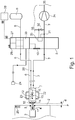
- Fig. 1 shows a schematic overview over the whole filling system according to the invention.
- a filling gun 1 is used to spray liquid carbon dioxide into a cooling cartridge 3 of a transport container 2.
- the liquid carbon dioxide is converted to carbon dioxide snow and some gaseous carbon dioxide as exhaust.
- the principles of this process for producing dry ice by spraying liquid carbon dioxide through a nozzle, are well known and can be found for example in DE 10 2010 013 056 A1 .
- the cooling cartridge 3, the transport container 2 and a filling terminal 4 in the transport container 2 are only shown in a schematic way.
- the filling process takes place by using a filling gun 1, which contains measuring and switching equipment all controlled by a control center 8.
- the control center 8 is also used to supply liquid carbon dioxide from a tank through an external supply line to the filling gun 1 as well as for collecting gaseous exhausted carbon dioxide to transport it through an external exhaust line 7 to the environment 35.
- the external supply line 6 and the external exhaust line 7 are connected to an internal supply line 16 and an internal exhaust line 17 in the filling gun 1.
- the filling gun 1 has two handles 22 with at least one integrated manual switch 23.
- an electromagnet 18 is located, which can cooperate with a ferromagnetic area 5 at the transport container 2 to bring and hold the filling gun 1 in a filling position P.
- Two activation sensors 14 measure the distance d of the filling gun 1 from the filling position P.
- the electromagnet 18 Only if the distance d is below a predetermined threshold, on operating person can activate the electromagnet 18 by pushing the manual switch 23.
- the electrical current flowing in the electromagnet 18 is measured in the control center 8, which is connected via signal lines 26 to the filling gun 1. If the measured electric current is in a certain predetermined range a filling valve 13 can be opened by the control center 8 to allow liquid carbon dioxide to flow to a filling end 11 to start the filling process by the production of dry ice.
- a pressure sensor 12 downstream of the filling vale 13 measures the pressure in the internal supply line 16 during the whole filling process. Only if the measured pressure is in a predetermined range, the filling process can be continued.
- the electromagnet 18 holds the filling gun 1 in place and an operating person can go to a display or touchscreen 10 of the control center 8 to observe or influence the filling process. If a new transport container 2 arrives, a reader 24 can be used to read information attached to the transport container 2, for example as a bar code.
- a communication module 27 in the control center 8 allows to communicate information about the arrived transport container to a customer 28 or data center and to exchange additional information.
- a receiver 29 of the control center also allows receiving additional external information, for example about temperatures, estimated transport time and the like.
- a calculation unit 30 in the control center 8 allows, if such information is not given from outside, to calculate the required amount of dry ice based on the information available and to open the filling valve for a certain time interval T to supply the required amount of liquid carbon dioxide.
- the control center 8 also contains a vacuum controller 33, which receives signals from a vacuum sensor 31 to control a safety flap 32. This allows keeping the pressure in the external exhaust line 7 in a desired range.
- a vacuum pump 34 is used to transport gaseous carbon dioxide through the external exhaust line 7 into the environment 35.
- the vacuum controller 33 allows to run the vacuum pump 34 and to nevertheless keep the under-pressure in the external exhaust line 7 in the predetermined range to avoid high under-pressure in the transport container 2, if no carbon dioxide is supplied over a certain period of time.
- Fig. 2 and 3 show in more detail the elements of the filling gun 1 in exploded views before assembling them.
- the filling gun 1 has a housing 37 bearing two handles 22 on opposite sides.
- the housing 37 contains if assembled an internal supply line 16 comprising a filling valve 13 and a pressure sensor 12 downstream of the filling valve 13.
- the housing also contains an internal exhaust line 17, whereby the internal supply line 16 and the internal exhaust line 17 form a filling end 11.
- the filling end 11 is designed as basically known from the prior art having a spraying nozzle and inlet openings to collect gaseous carbon dioxide.
- the internal supply line 16 is surrounded by the internal exhaust line 17.
- a ring shaped electromagnet 18 with a core 19 and a coil 20 surrounds the internal exhaust line 17 at a certain distance from the filling end 11.
- Two activation sensors 14 are located at the housing 37 in a position directed to the filling end 11 to allowing measuring the distance to the transport container 2, what means the distance d to a filling position P.
- Two manual switches 23 connected in series provide the additional safety that an operating person can only activate the electromagnet 18, if he/she handles the filling gun 1 with both hands.
- An electric heating 21 can be located in the area of the filling valve 13 and the pressure sensor 12 to keep this area free of ice. All sensors and electric devices are connected via a signal line 26 (not shown in fig. 2 and 3 ) to a control center 8. Couplings 15 are provided at the filling gun 1 to interconnect the internal supply line 16 to an external supply line 6 and the internal exhaust line 17 to an external exhaust line 7. As the filling gun 1 may be too heavy to be held by an operating person it is balanced by a not shown counterweight carrying the filling gun 1 by a suspension 38.
- a balancing plate 36 allows fixing the suspension 38 at different balancing positions to allow adapting the balanced position of the filling gun 1 to different situations for example concerning the external supply line 6 and the external exhaust line 7. The suspension 38 nevertheless allows to three dimensionally move the filling gun 1 and avoids unnecessary pivoting in vertical or horizontal direction.
- valves in series can be used in the filling gun. In this case it is possible to open one of them as long as the electromagnet is active in the correct filling position, and to use the second one as filling valve by opening it for a certain time interval T. This provides a high safety against unintentional spraying of liquid carbon dioxide in case of failure of one of the valves.
- Fig. 4 shows in a schematic diagram the behavior of the pressure measured by the pressure sensor 12, if the filling valve 13 is opened for a time interval T.
- the time t is given by the x-achsis, the y-achsis shows the pressure.
- the pressure soon raises over a threshold, after the filling valve 12 is opened. If the filling valve 12 is closed, it can take some time until the internal supply line 16 is empty. For this reason it can be more precise to measure an actual filling time Ta, which is the time during which the pressure in the internal supply line measured by the pressure sensor 12 is higher than a given threshold.
- the actual filling time interval allows a precise determination of the amount of carbon dioxide snow filled into the cooling cartridge 3 of the transport container 2.
- the described filling system with a filling gun containing all measuring and switching devices to safely and reliably operate the filling systems allows filling in a reproducible manner exactly required amounts of carbon dioxide snow into a transport container. Any problems coming up during the filling process can be measured, documented and be used to switch off the filling process or to correct it.
Landscapes
- Engineering & Computer Science (AREA)
- Chemical & Material Sciences (AREA)
- Combustion & Propulsion (AREA)
- Physics & Mathematics (AREA)
- Mechanical Engineering (AREA)
- Thermal Sciences (AREA)
- General Engineering & Computer Science (AREA)
- Chemical Kinetics & Catalysis (AREA)
- Basic Packing Technique (AREA)
- Filling Or Discharging Of Gas Storage Vessels (AREA)
Description
- The present invention is directed to a filling system for filling a cooling cartridge in a transport container via a filling terminal with carbon dioxide snow (dry ice). It is also directed to a filling gun for such a filling system and to a method of filling dry ice into a transport container. The principles of transporting goods in a thermally insulated container and of the filling of such containers with carbon dioxide snow are for example known from
DE 10 2010 013 056 A1 . However, in this document the containers are moved and docked to a stationary filling station, what is not always the best choice in a logistic chain. Thus, filling guns have already been used to inject liquid carbon dioxide into transport containers to produce carbon dioxide snow inside the container and for collecting exhausted gaseous carbon dioxide during the filling process. However, so far manually introducing a filling end of a filling gun into a filling terminal of a transport container requires certain skills of the operating personal and the reliability of the process and the reproducibility of required amounts of carbon dioxide snow are not very high. -
EP1724538 A1 discloses a filling sytem, a filling gun and a method for filling a cooling cartridge according to the preamble of claims 1, 3 and 5. - It is therefore an object of the present invention to create a filling system and a filling method, which are simple and safe in use and allow the filling of transport containers with exactly the required amounts of carbon dioxide snow. Moreover, it is an object of the present invention to create a filling gun, the handling of which is easy and safe and which can be moved manually or by a robotic arm to transport containers at different positions.
- The described problems are solved by a filling system according to independent claim 1, a filling gun according to independent claim 3 and a filling method according to independent claim 5. Additional improvements, embodiments and features, which can also be used in combination with each other, are described in the respective dependent claims.
- A filling system according to the present invention for filling a cooling cartridge in a transport container via a filling terminal with carbon dioxide snow comprises:
- an external supply line for supplying liquid carbon dioxide,
- an external exhaust line for conducting gaseous carbon dioxide to the environment,
- a filling gun having an internal supply line and an internal exhaust line, to which the external supply line and the external exhaust line are coupled and which form a filling end where the internal supply line is surrounded by the internal exhaust line, which filling end can be introduced into the filling terminal,
- at least one electromagnet for holding the filling gun in a filling position,
- a filling valve for opening and closing the internal supply line,
- a pressure sensor downstream of the filling valve,
- at least one activation sensor measuring the distance of the filling gun to a filling position,
- a control center for controlling the opening and closing of the filling valve in dependency of the values measured by the pressure sensor and an electric current flow in the electromagnet.
- This filling system is especially designed for high safety and reliability. If a filling gun is introduced manually or by a robotic arm into a filling terminal of a transport container at least five parameters have to be taken into account. The filling gun usually can be moved in three dimensions and can be pivoted horizontally and vertically. An operator has to take care that the filling end of the filling gun hits an opening of the filling terminal and that the filling gun is aligned in a correct way, what usually means that a longitudinal axis of the filling gun points in a normal direction of a wall of the transport container. Only if all parameters are correct a tight connection between the filling gun and the filling terminal is possible and a reproducible filling process can be started. For this reason according to the present invention at least one electromagnet and at least one activation sensor play an important role for the correct positioning and the maintenance and surveillance of a correct position of the filling gun during the whole filling process. Although magnetic couplings are known in filling systems, so far permanent magnets were used or electromagnets were only activated or deactivated to establish a connection or to open it. However, it is also possible to measure the electric current flowing in an electromagnet after having activated it. This allows to measure, whether the electromagnet has found a predetermined connecting position and whether it is maintaining the connection. A filling valve can be blocked until the electric current flow in the electromagnet has reached a certain predetermined range and/or can be stopped as soon as the electric current flow exceeds the predetermined range. This makes sure that filling only takes place when the filling gun is in the correct filling position and is stopped as soon as the electric current detects any displacement. On the other hand such an electromagnet can disturb the positioning of the filling gun if it is activated too early or at a time, when the filling gun is not in a correct position or under a certain angle in horizontal and/or vertical direction. In this case the magnetic force could even damage the filling gun. For this reason the activation of the electromagnet is dependent on at least one activation sensor measuring the distance of the filling gun to the filling terminal. Such an activation sensor, preferably two on two sides of the filling gun, allows making sure that the electromagnet is only activated when the filling gun is almost in the correct filling position and only needs a final correction, which can be achieved by magnetic force.
- Another safety feature of the filling gun is a pressure sensor downstream of the filling valve, which allows detecting the pressure of the liquid carbon dioxide with a sensor which for example allows to determine any malfunction in the system and to document the pressure during the whole filling process, if required. A control center controls the opening and closing of the filling valve in dependency of the values measured by the pressure sensor and an electric current flow in the electromagnet. This means that the filling system according to the present invention has all measuring and switching means in the filling gun, while a control and supply is done by a control center to which the filling gun is connected.
- In a preferred embodiment of the invention there is another safety feature provided by a vacuum control circuit for keeping the pressure in the external exhaust line in a predetermined range. While usual transport containers under overpressure simply open a door or flap or blow some gas through their sealing lips, they cannot withstand in the same way a high under-pressure. This means that the external exhaust line should not be connected to a vacuum pump only, but the pressure in the external exhaust line should be controlled and kept in a predetermined range of under-pressure. If the pressure is below a certain threshold the vacuum control circuit can for example open a safety flap, which connects the external exhaust line with the environment. This makes sure that also the pressure in the transport container does not fall below this threshold even in case that no liquid carbon dioxide is supplied through the filling gun.
- A filling gun according to the present invention for the described filling system comprises:
- at least one electromagnet for cooperating with a ferromagnetic area of a transport container having a filling terminal,
- at least one activation sensor measuring the distance of the filling gun to the filling terminal,
- couplings for connecting the filling gun with an external supply line for liquid carbon dioxide and with an external exhaust line for gaseous carbon dioxide,
- a filling end forming an arrangement of an internal supply line for liquid carbon dioxide as inner part and an internal exhaust line for gaseous carbon dioxide as outer part surrounding the internal supply line,
- a filling valve for opening and closing the internal supply line,
- a pressure sensor downstream of the filling valve,
- at least one handle to manually move the filling gun in three dimensions containing at least one integrated manual switch for activating the electromagnet, if the activation sensor measures a value for the distance of the filling gun to a filling position in a predetermined range.
- As will be described below the combination of activation sensor, electromagnet, filling valve and pressure sensor all integrated in the filling gun allow a very safe and reliable filling process. For allowing an operating person to easily handle the filling gun it is provided with at least one handle to manually move the filling gun in three dimensions and, of course, to correct its horizontal or vertical angle if required for bringing a filling gun almost into the final filling position. At this stage at least one integrated manual switch allows to activate the electromagnet, but only if the at least one activation sensor measures a distance in a predetermined range. It is preferred to use two handles on both horizontal sides of the filling gun in combination with two activation sensors on both sides of the filling gun as well as two manual switches integrated in both handles to force an operating person to operate the filling gun with both hands on both handles and allowing this person to activate the electromagnet by pushing these manual switches, only if both activation sensors measure a distance below a certain predetermined distance. In this case the electromagnet will finally correct the position of the filling gun and safely connect it with the filling terminal and keep it there until the electromagnet is deactivated. As long as the electromagnet is activated, an operating person needs not to keep the hands on the handles, but is free for other activities, in particular inputting information into an interface of the control center.
- In a preferred embodiment of the invention the electromagnet in the filling gun is designed such that its magnetic circuit is open when the electromagnet is not cooperating with the ferromagnetic area of the transport container and is substantially closed when the electromagnet is cooperating with the ferromagnetic area. This allows to measure whether or not the filling gun is (still) in the correct filling position and to use this signal as additional safety feature for the filling process.
- The present invention also provides a method for filling a cooling cartridge in a transport container with a predetermined amount of carbon dioxide snow comprising the following steps:
- approaching a filling terminal of the transport container with a filling gun having an internal supply line for liquid carbon dioxide and an internal exhaust line for gaseous carbon dioxide both forming a filling end,
- measuring the distance of the filling gun from a filling position in the transport container by at least one activation sensor,
- supplying an electric current to at least one electromagnet cooperating with a ferromagnetic area of the transport container for bringing and holding the filling gun in a filling position, when the distance measured is below a predetermined threshold,
- measuring the electric current flow in the electromagnet,
- opening a filling valve in the internal supply line, if the electric current measured is in a predetermined range, and keeping the filling valve open for a predetermined time interval,
- measuring the pressure in the internal supply line by a pressure sensor downstream of the filling valve,
- closing the filling valve, if the measured electric current in the electromagnet exceeds the predetermined electric current range and/or if the measured pressure in the internal supply line exceeds a predetermined pressure range or if the time interval has expired.
- The method according to the present invention describes a very safe and reliable process, which allows filling transport containers with carbon dioxide snow without docking them to a stationary filling station and without strong restrictions for the size, the position, and the alignment of the transport container. It would even be possible to move the container during the filling process. To safely and correctly position the filling gun in the filling terminal of the transport container the distance of the filling gun from a filling position is measured by at least one activation sensor. An electromagnet can only be activated, if the distance is below a predetermined threshold. After activation of the electromagnet the electric current flow in the electromagnet is measured, what allows to recognize whether the electromagnet is (still) in the correct position for filling. The filling valve can only be opened if the filling gun is in the correct filling position. For filling a predetermined amount of carbon dioxide snow into the transport container a filling valve is opened for a predetermined time interval. During the whole filling process the pressure in the internal supply line is measured by a pressure sensor downstream of the filling valve, what allows a surveillance and documentation of the whole filling process. In particular it is possible to detect any blockage in the filling end or the transport container and to stop the filling process accordingly. If anything goes wrong during the filling process either on the mechanical side or on the electrical side, the filling process can be interrupted based on the measured signals, otherwise it can be ended if the predetermined interval has expired.
- It should be noted that an activation sensor in the meaning of the present invention can be any device, which allows verifying whether or not the filling gun is close to the correct filling position. Thus, it would also be possible to use a robotic arm and its positioning equipment to produce such a verifying signal for activation of the electromagnet.
- According to a preferred embodiment of the invention it is possible to measure an actual filling time interval by measuring the time between a pressure raise over and a pressure drop at the pressure sensor in the supply line under a predetermined value. This means that not the opening and closing time of the filling valve determines the filling interval, but the measured pressure eliminates any delay of the valve or the supply system. It is also possible to use a combination of the information available from the pressure sensor and the filling valve to determine the actual filling time interval. Based on tests and experimental data this allows a very precise documentation of the amount of carbon dioxide snow filled into the transport container.
- To make the docking of the filling gun to the filling terminal as easy and safe as possible, it is preferred to use two activation sensors measuring the distance between the filling gun and the transport container and to allow activating the electromagnet only, if both activation sensors measure a distance below a predetermined threshold.
- In another preferred embodiment a control center is used to control the whole filling process. It is interconnected to the filling gun for transmitting measured values and signals for activating the electromagnet and opening of the filling valve. The control center is additionally equipped with a reading instrument, in particular a bar code reader, for reading and transmitting information attached to the transport container. This allows for each individual container to be filled to first obtaining information about its size, its content and an estimated transport time. Instead of a bar code also other methods for storing and supplying information can be used, especially systems for near field communication or similar devices.
- Moreover, in a preferred embodiment of the invention the control center has a communication module to communicate with a customer and/or a data center. This allows a lot of additional modifications of the exchanged information and keeps the customer informed about any progress on the transport chain.
- In another embodiment of the invention the control center has a receiver for receiving information about the environment and transport conditions, in particular about temperatures in storage and transport facilities, estimated transport duration and the like. This information is helpful to better calculate the required amount of carbon dioxide snow for a certain container.
- If the control center is designed for not only using externally given information about filling amounts or filling times, it is preferably equipped with a calculation unit, which is able to internally calculate the required amount of carbon dioxide snow depending on read, received and/or transmitted data and to calculate a resulting time interval for opening the supply valve.
- The described equipment of the control center also allows measuring and communicating information about the filling process, especially the actual filling time interval and/or any error due to earlier closing of the filling valve and the like. This information can be communicated via the communication module to a customer or data center to be verified and/or stored.
- Of course, the abilities of the control center also allow to only releasing a transport container for further handling, if an approval by the customer or a data center is received via the communication module.
- The safety of the whole filling process is further improved according to the present invention by a vacuum control circuit, which keeps the pressure in the external exhaust line in a predetermined range. This avoids under-pressure and a possible implosion of a transport container in case of connecting it to the exhaust line without supplying it with liquid carbon dioxide.
- Preferred embodiments and their methods of use are described in the following with reference to the drawings. However, the invention is not restricted to the shown embodiments and different features shown in different embodiments can also be combined with each other without exceeding the scope of the present invention.
-
Fig. 1 shows a schematic overview over the whole filling system, -
Fig. 2 shows a perspective exploded view of a filling gun according to the invention, -
Fig. 3 shows a perspective exploded view of the interior of the filling gun according tofig. 2 and -
Fig. 4 shows in a schematic diagram the pressure measured by a pressure sensor downstream of a filling valve during a filling process. -
Fig. 1 shows a schematic overview over the whole filling system according to the invention. A filling gun 1 is used to spray liquid carbon dioxide into a cooling cartridge 3 of a transport container 2. The liquid carbon dioxide is converted to carbon dioxide snow and some gaseous carbon dioxide as exhaust. The principles of this process for producing dry ice by spraying liquid carbon dioxide through a nozzle, are well known and can be found for example inDE 10 2010 013 056 A1external exhaust line 7 to theenvironment 35. The external supply line 6 and theexternal exhaust line 7 are connected to aninternal supply line 16 and aninternal exhaust line 17 in the filling gun 1. The filling gun 1 has twohandles 22 with at least one integratedmanual switch 23. In front of the filling gun 1 anelectromagnet 18 is located, which can cooperate with a ferromagnetic area 5 at the transport container 2 to bring and hold the filling gun 1 in a filling position P.Two activation sensors 14 measure the distance d of the filling gun 1 from the filling position P. Only if the distance d is below a predetermined threshold, on operating person can activate theelectromagnet 18 by pushing themanual switch 23. The electrical current flowing in theelectromagnet 18 is measured in the control center 8, which is connected viasignal lines 26 to the filling gun 1. If the measured electric current is in a certain predetermined range a fillingvalve 13 can be opened by the control center 8 to allow liquid carbon dioxide to flow to a fillingend 11 to start the filling process by the production of dry ice. Apressure sensor 12 downstream of the fillingvale 13 measures the pressure in theinternal supply line 16 during the whole filling process. Only if the measured pressure is in a predetermined range, the filling process can be continued. During the filling process theelectromagnet 18 holds the filling gun 1 in place and an operating person can go to a display ortouchscreen 10 of the control center 8 to observe or influence the filling process. If a new transport container 2 arrives, areader 24 can be used to read information attached to the transport container 2, for example as a bar code. Acommunication module 27 in the control center 8 allows to communicate information about the arrived transport container to acustomer 28 or data center and to exchange additional information. - A
receiver 29 of the control center also allows receiving additional external information, for example about temperatures, estimated transport time and the like. Acalculation unit 30 in the control center 8 allows, if such information is not given from outside, to calculate the required amount of dry ice based on the information available and to open the filling valve for a certain time interval T to supply the required amount of liquid carbon dioxide. - The control center 8 also contains a
vacuum controller 33, which receives signals from avacuum sensor 31 to control asafety flap 32. This allows keeping the pressure in theexternal exhaust line 7 in a desired range. - Usually a
vacuum pump 34 is used to transport gaseous carbon dioxide through theexternal exhaust line 7 into theenvironment 35. Thevacuum controller 33 allows to run thevacuum pump 34 and to nevertheless keep the under-pressure in theexternal exhaust line 7 in the predetermined range to avoid high under-pressure in the transport container 2, if no carbon dioxide is supplied over a certain period of time. -
Fig. 2 and3 show in more detail the elements of the filling gun 1 in exploded views before assembling them. The filling gun 1 has ahousing 37 bearing twohandles 22 on opposite sides. Thehousing 37 contains if assembled aninternal supply line 16 comprising a fillingvalve 13 and apressure sensor 12 downstream of the fillingvalve 13. The housing also contains aninternal exhaust line 17, whereby theinternal supply line 16 and theinternal exhaust line 17 form a fillingend 11. In the shown example the fillingend 11 is designed as basically known from the prior art having a spraying nozzle and inlet openings to collect gaseous carbon dioxide. Theinternal supply line 16 is surrounded by theinternal exhaust line 17. A ring shapedelectromagnet 18 with acore 19 and acoil 20 surrounds theinternal exhaust line 17 at a certain distance from the fillingend 11. Twoactivation sensors 14 are located at thehousing 37 in a position directed to the fillingend 11 to allowing measuring the distance to the transport container 2, what means the distance d to a filling position P. Amanual switch 23 in one of thehandles 22, preferably twomanual switches 23 in bothhandles 22, allow an operating person to active theelectromagnet 18, if the distance d to the filling position P is below a threshold. Twomanual switches 23 connected in series provide the additional safety that an operating person can only activate theelectromagnet 18, if he/she handles the filling gun 1 with both hands. - An
electric heating 21 can be located in the area of the fillingvalve 13 and thepressure sensor 12 to keep this area free of ice. All sensors and electric devices are connected via a signal line 26 (not shown infig. 2 and3 ) to a control center 8.Couplings 15 are provided at the filling gun 1 to interconnect theinternal supply line 16 to an external supply line 6 and theinternal exhaust line 17 to anexternal exhaust line 7. As the filling gun 1 may be too heavy to be held by an operating person it is balanced by a not shown counterweight carrying the filling gun 1 by asuspension 38. A balancingplate 36 allows fixing thesuspension 38 at different balancing positions to allow adapting the balanced position of the filling gun 1 to different situations for example concerning the external supply line 6 and theexternal exhaust line 7. Thesuspension 38 nevertheless allows to three dimensionally move the filling gun 1 and avoids unnecessary pivoting in vertical or horizontal direction. - It should be mentioned that for safety reasons two valves in series can be used in the filling gun. In this case it is possible to open one of them as long as the electromagnet is active in the correct filling position, and to use the second one as filling valve by opening it for a certain time interval T. This provides a high safety against unintentional spraying of liquid carbon dioxide in case of failure of one of the valves.
-
Fig. 4 shows in a schematic diagram the behavior of the pressure measured by thepressure sensor 12, if the fillingvalve 13 is opened for a time interval T. The time t is given by the x-achsis, the y-achsis shows the pressure. As can be seen from the diagram the pressure soon raises over a threshold, after the fillingvalve 12 is opened. If the fillingvalve 12 is closed, it can take some time until theinternal supply line 16 is empty. For this reason it can be more precise to measure an actual filling time Ta, which is the time during which the pressure in the internal supply line measured by thepressure sensor 12 is higher than a given threshold. The actual filling time interval allows a precise determination of the amount of carbon dioxide snow filled into the cooling cartridge 3 of the transport container 2. It also provides an additional safety, if the filling gun 1 is not released from the filling position P until the pressure is below the threshold. This avoids unintended spraying of carbon dioxide into theenvironment 35 in case of a delayed closing of the fillingvalve 13 by malfunction or for systematic reasons. - The described filling system with a filling gun containing all measuring and switching devices to safely and reliably operate the filling systems allows filling in a reproducible manner exactly required amounts of carbon dioxide snow into a transport container. Any problems coming up during the filling process can be measured, documented and be used to switch off the filling process or to correct it.
-
- 1
- filling gun
- 2
- transport container
- 3
- cooling cartridge
- 4
- filling terminal
- 5
- ferromagnetic area
- 6
- external supply line
- 7
- external exhaust line
- 8
- control center
- 9
- tank for liquid carbon dioxide
- 10
- display/touchscreen
- 11
- filling end
- 12
- pressure sensor
- 13
- filling valve
- 14
- activation sensor
- 15
- coupling
- 16
- internal supply line
- 17
- internal exhaust line
- 18
- electromagnet
- 19
- core of the electromagnet
- 20
- coil of the electromagnet
- 21
- electric heating
- 22
- handle
- 23
- manual switch
- 24
- reader
- 25
- information carrier
- 26
- signal line
- 27
- communication module
- 28
- customer/data center
- 29
- receiver
- 30
- calculation unit
- 31
- vacuum sensor
- 32
- safety flap
- 33
- vacuum controller
- 34
- vacuum pump
- 35
- environment
- 36
- balancing plate
- 37
- housing
- 38
- suspension
- P
- filling position
- d
- distance between filling gun and transport container
- t
- time
- T
- time interval
- Ta
- actual filling time interval
Claims (14)
- Filling system for filling a cooling cartridge (3) in a transport container (2) via a filling terminal (4) with carbon dioxide snow comprising:- an external supply line (6) for supplying liquid carbon dioxide,- an external exhaust line (7) for conducting gaseous carbon dioxide to the environment (32),- a filling gun (1), able to be introduced manually or by a robotic arm into the filling terminal of the transport container, having an internal supply line (16) and an internal exhaust line (17), to which the external supply line (6) and the external exhaust line (7) are coupled and which form a filling end (11), wherein the internal supply line (16) is surrounded by the internal exhaust line (17), which filling end (11) can be introduced into the filling terminal (4),- at least one electromagnet (18) for holding the filling gun (1) in a filling position (P),- a filling valve (13) for opening and closing the internal supply line (16),- at least one activation sensor (14) measuring the distance (d) of the filling gun (1) from the filling terminal (4),characterized by- a pressure sensor (12) downstream of the filling valve (13),- a control center (8) for controlling the opening and closing of the filling valve (13) in dependency of the values measured by the pressure sensor (12) and an electric current flow (I) in the electromagnet (18),wherein the activation of said at least one electromagnet (18) being dependent on said at least one activation sensor (14) measuring the distance of the filling gun (1) to the filling terminal(4).
- Filling system according to claim 1, further comprising a vacuum control circuit (33) for keeping the pressure in the external exhaust line (7) in a predetermined range.
- Filling gun (1) for a filling system according to claim 1, comprising- at least one electromagnet (18) for cooperating with a ferromagnetic area (5) of a transport container (2) having a filling terminal (4),- at least one activation sensor (14) measuring the distance (d) of the filling gun (1) to the filling terminal (4),- couplings (15) for connecting the filling gun (1) with an external supply line (6) for liquid carbon dioxide and with an external exhaust line (7) for gaseous carbon dioxide,- a filling end (11) forming an arrangement of an internal supply line (16) for liquid carbon dioxide as inner part and an internal exhaust line (17) for gaseous carbon dioxide as outer part surrounding the internal supply line (16),- a filling valve (13) for opening and closing the internal supply line (16),characterized by:- a pressure sensor (12) downstream of the filling valve (13),- a handle (22) to manually move the filling gun (1) in three dimensions containing at least one integrated manual switch (23) for activating the electromagnet (18), if the activation sensor (14) measures a value for the distance (d) of the filling gun (1) to the filling position (P) in a predetermined range.
- Filling gun (1) according to claim 3, wherein the electromagnet (18) is designed such that its magnetic circuit is open when not cooperating with the ferromagnetic area (5) of the transport container (2) and closed when it is cooperating with the ferromagnetic area (5).
- Method for filling a cooling cartridge (3) in a transport container (2) with a predetermined amount of carbon dioxide snow comprising the following steps:- approaching a filling terminal (4) of the transport container (2) with a filling gun (1) having an internal supply line (16) for liquid carbon dioxide and an internal exhaust line (17) for gaseous carbon dioxide both forming a filling end (11), characterized by the implementation of the following steps- measuring the distance (d) of the filling gun (1) from a filling position (P) by at least one activation sensor (14),- supplying an electric current to at least one electromagnet (18) cooperating with a ferromagnetic area (5) of the transport container (2) for bringing and holding the filling gun (1) in the filling position (P), when the distance (d) measured is below a predetermined threshold,- measuring the electric current flow in the electromagnet (18),- opening a filling valve (13) in the internal supply line (16), if the electric current measured is in a predetermined range, and keeping the filling valve (13) open for a predetermined time interval (T),- measuring the pressure in the internal supply line (16) by a pressure sensor (12) downstream of the filling valve (13),- closing the filling valve (13), if the measured electric current in the electromagnet (18) exceeds the predetermined electric current range and/or if the measured pressure in the internal supply line (16) exceeds a predetermined pressure range or if the time interval (T) has expired.
- Method according to claim 5, wherein an actual filling time interval (Ta) is determined by measuring the time between a pressure raise and a pressure drop at the pressure sensor (12) in the supply line (16) over and under, respectively, a predetermined value.
- Method according to claim 5 or 6, wherein two activation sensors (14) are arranged at different sides of the filling gun (1) and the electromagnet (18) can only be supplied with an electric current, if the distance (d) measured by both activation sensors (14) is below the predetermined threshold.
- Method according to one of claims 5 to 7, wherein the filling process is controlled by a control center (8) interconnected to the filling gun (1) for transmitting measured values and signals for activating the electromagnet (18) and opening of the filling valve (13) and wherein the control center (8) is equipped with a reading instrument (24), in particular a bar code reader, for reading and transmitting information attached to the transport container (2).
- Method according to one of claims 5 to 8, wherein the control center (8) has a communication module (27) to communicate with a customer and/or a data center (28).
- Method according to one of claims 5 to 9, wherein the control center (8) has a receiver (29) for receiving information about the environment (34) and transport conditions, in particular about temperatures in storage and transport facilities, estimated transport duration and the like.
- Method according to one of claims 5 to 10, wherein the control center (8) has a calculation unit (30) to calculate the required amount of carbon dioxide snow depending on read, received and/or transmitted data and the resulting time interval (T) for opening the supply valve (13).
- Method according claims 6 and 9, wherein the actual filling time interval (Ta) and/or any error due to earlier closing of the filling valve (13) is communicated via the communication module (27) to a customer or data center (28) to be verified and/or stored.
- Method according to claim 12, wherein the transport container (2) is only released for further handling, if an approval by the customer or a data center (28) is received via the communication module (27).
- Method according to one of claims 5 to 13, wherein a vacuum control circuit (10) keeps the pressure in the external exhaust line (7) in a predetermined range.
Priority Applications (5)
| Application Number | Priority Date | Filing Date | Title |
|---|---|---|---|
| HUE14197807A HUE043584T2 (en) | 2014-12-12 | 2014-12-12 | Filling system and filling gun for filling carbon dioxide snow into a transport container |
| ES14197807T ES2725886T3 (en) | 2014-12-12 | 2014-12-12 | Filling system and filling gun to fill carbon dioxide snow in a transport container |
| EP14197807.2A EP3032195B1 (en) | 2014-12-12 | 2014-12-12 | Filling system and filling gun for filling carbon dioxide snow into a transport container |
| PL14197807T PL3032195T3 (en) | 2014-12-12 | 2014-12-12 | Filling system and filling gun for filling carbon dioxide snow into a transport container |
| PT14197807T PT3032195T (en) | 2014-12-12 | 2014-12-12 | Filling system and filling gun for filling carbon dioxide snow into a transport container |
Applications Claiming Priority (1)
| Application Number | Priority Date | Filing Date | Title |
|---|---|---|---|
| EP14197807.2A EP3032195B1 (en) | 2014-12-12 | 2014-12-12 | Filling system and filling gun for filling carbon dioxide snow into a transport container |
Publications (2)
| Publication Number | Publication Date |
|---|---|
| EP3032195A1 EP3032195A1 (en) | 2016-06-15 |
| EP3032195B1 true EP3032195B1 (en) | 2019-03-27 |
Family
ID=52144406
Family Applications (1)
| Application Number | Title | Priority Date | Filing Date |
|---|---|---|---|
| EP14197807.2A Active EP3032195B1 (en) | 2014-12-12 | 2014-12-12 | Filling system and filling gun for filling carbon dioxide snow into a transport container |
Country Status (5)
| Country | Link |
|---|---|
| EP (1) | EP3032195B1 (en) |
| ES (1) | ES2725886T3 (en) |
| HU (1) | HUE043584T2 (en) |
| PL (1) | PL3032195T3 (en) |
| PT (1) | PT3032195T (en) |
Families Citing this family (9)
| Publication number | Priority date | Publication date | Assignee | Title |
|---|---|---|---|---|
| EP2881646A1 (en) | 2013-12-05 | 2015-06-10 | YARA International ASA | Method and system for filling thermally insulated containers with liquid carbon dioxide |
| US11384904B2 (en) | 2013-12-05 | 2022-07-12 | Praxair Technology, Inc. | Method and system for filling thermally insulated containers with liquid carbon dioxide |
| DE102016100243A1 (en) * | 2016-01-08 | 2017-07-13 | Rehau Ag + Co. | Method for painting automotive plastic components |
| US10712072B2 (en) | 2016-07-11 | 2020-07-14 | Praxair Technology, Inc. | Transportable container, charger system, method and kit for generation of carbon dioxide snow block in-situ within the transportable container for preservation of items stored therewithin |
| US11248838B2 (en) | 2016-07-11 | 2022-02-15 | Praxair Technology, Inc. | Transportable container, charger system, method and kit for generation of carbon dioxide snow block in-situ within the transportable container for preservation of items stored there within |
| EP3358512A1 (en) * | 2017-02-03 | 2018-08-08 | Air Liquide Deutschland GmbH | Method for distributing heat-sensitive products |
| US11352262B2 (en) | 2017-12-18 | 2022-06-07 | Praxair Technology, Inc. | Methods for automatic filling, charging and dispensing carbon dioxide snow block |
| US11193708B2 (en) | 2017-12-20 | 2021-12-07 | Praxair Technology, Inc. | Methods for pre-charging carbon dioxide snow |
| EP3664000A1 (en) * | 2018-12-04 | 2020-06-10 | L'Air Liquide Société Anonyme pour l'Etude et l'Exploitation des Procédés Georges Claude | Cold chain management |
Citations (3)
| Publication number | Priority date | Publication date | Assignee | Title |
|---|---|---|---|---|
| US5715685A (en) * | 1994-12-12 | 1998-02-10 | Colpo Co., Ltd. | Method and apparatus for transporting/storing chilled goods |
| US6220051B1 (en) * | 1998-06-16 | 2001-04-24 | Cool Pack System Corp. | Compact rapid chilling system and method for reserving cold |
| EP1724538A1 (en) * | 2005-05-20 | 2006-11-22 | Olivo | Logistic system for the transportation of fresh or frozen products |
Family Cites Families (2)
| Publication number | Priority date | Publication date | Assignee | Title |
|---|---|---|---|---|
| DE19808267A1 (en) * | 1998-02-27 | 1999-09-02 | Messer France Sa | Filling and removal module for a cooling module and method for filling a cooling module |
| DE102010013056B4 (en) | 2010-03-26 | 2018-05-09 | Tkt Gassysteme Gmbh | Method and device for filling a cooling cell of an insulating container with a cooling medium |
-
2014
- 2014-12-12 PT PT14197807T patent/PT3032195T/en unknown
- 2014-12-12 EP EP14197807.2A patent/EP3032195B1/en active Active
- 2014-12-12 HU HUE14197807A patent/HUE043584T2/en unknown
- 2014-12-12 PL PL14197807T patent/PL3032195T3/en unknown
- 2014-12-12 ES ES14197807T patent/ES2725886T3/en active Active
Patent Citations (3)
| Publication number | Priority date | Publication date | Assignee | Title |
|---|---|---|---|---|
| US5715685A (en) * | 1994-12-12 | 1998-02-10 | Colpo Co., Ltd. | Method and apparatus for transporting/storing chilled goods |
| US6220051B1 (en) * | 1998-06-16 | 2001-04-24 | Cool Pack System Corp. | Compact rapid chilling system and method for reserving cold |
| EP1724538A1 (en) * | 2005-05-20 | 2006-11-22 | Olivo | Logistic system for the transportation of fresh or frozen products |
Also Published As
| Publication number | Publication date |
|---|---|
| EP3032195A1 (en) | 2016-06-15 |
| HUE043584T2 (en) | 2019-08-28 |
| PT3032195T (en) | 2019-05-30 |
| PL3032195T3 (en) | 2019-08-30 |
| ES2725886T3 (en) | 2019-09-30 |
Similar Documents
| Publication | Publication Date | Title |
|---|---|---|
| EP3032195A1 (en) | Filling system and filling gun for filling carbon dioxide snow into a transport container | |
| US11753289B2 (en) | Fluid filling systems and methods | |
| DK3161371T3 (en) | DEVICE AND PROCEDURE FOR SUPPLYING PRESSURE FLUID | |
| KR102440278B1 (en) | Filling station for gas bottles and filling method | |
| US11624464B2 (en) | Device for supplying pressurized fluid, and assembly for storing pressurized fluid comprising such a device | |
| US20180017256A1 (en) | Liquid gas system | |
| KR20120120844A (en) | Water purifier having a safety device for water intake | |
| CN102326018A (en) | Method and apparatus for filling tank with cryogenic liquid | |
| US10317014B2 (en) | Flow variation system | |
| EP2884437B1 (en) | Method, control unit and computer program product for controlling a product loading state of at least one compartment in a tank vehicle | |
| EP2168687A1 (en) | Color change valve assembly with sensors | |
| KR20120060083A (en) | Method of determining the relations of hydrogen-absorbing alloys | |
| KR20150078667A (en) | Real-time monitoring system of the position and the internal state of the container of hazardous materials | |
| PL1935839T3 (en) | Device for filling liquids in vessels or for rinsing vessels and method for detecting control function failures in such devices | |
| JP2007015766A (en) | Dispense head and sparkling beverage feeder using the same | |
| KR102455890B1 (en) | Air shooter system | |
| JP2017133624A (en) | Fuel gas charging apparatus and fuel gas charging method | |
| KR101040442B1 (en) | Test device for shock pressure relay | |
| KR20140059541A (en) | Automatic fire extinguishing system and method | |
| KR20230091673A (en) | Remote Control and Remote Monitoring System for Tank Lorry | |
| WO2016146775A2 (en) | A shut-off valve | |
| JP2015196514A (en) | Fuel supply device | |
| JP6488846B2 (en) | Powder fire extinguishing equipment | |
| KR20100095502A (en) | Beer supplying assembly |
Legal Events
| Date | Code | Title | Description |
|---|---|---|---|
| PUAI | Public reference made under article 153(3) epc to a published international application that has entered the european phase |
Free format text: ORIGINAL CODE: 0009012 |
|
| AK | Designated contracting states |
Kind code of ref document: A1 Designated state(s): AL AT BE BG CH CY CZ DE DK EE ES FI FR GB GR HR HU IE IS IT LI LT LU LV MC MK MT NL NO PL PT RO RS SE SI SK SM TR |
|
| AX | Request for extension of the european patent |
Extension state: BA ME |
|
| STAA | Information on the status of an ep patent application or granted ep patent |
Free format text: STATUS: REQUEST FOR EXAMINATION WAS MADE |
|
| 17P | Request for examination filed |
Effective date: 20161215 |
|
| RBV | Designated contracting states (corrected) |
Designated state(s): AL AT BE BG CH CY CZ DE DK EE ES FI FR GB GR HR HU IE IS IT LI LT LU LV MC MK MT NL NO PL PT RO RS SE SI SK SM TR |
|
| GRAP | Despatch of communication of intention to grant a patent |
Free format text: ORIGINAL CODE: EPIDOSNIGR1 |
|
| STAA | Information on the status of an ep patent application or granted ep patent |
Free format text: STATUS: GRANT OF PATENT IS INTENDED |
|
| INTG | Intention to grant announced |
Effective date: 20181016 |
|
| GRAS | Grant fee paid |
Free format text: ORIGINAL CODE: EPIDOSNIGR3 |
|
| GRAA | (expected) grant |
Free format text: ORIGINAL CODE: 0009210 |
|
| STAA | Information on the status of an ep patent application or granted ep patent |
Free format text: STATUS: THE PATENT HAS BEEN GRANTED |
|
| AK | Designated contracting states |
Kind code of ref document: B1 Designated state(s): AL AT BE BG CH CY CZ DE DK EE ES FI FR GB GR HR HU IE IS IT LI LT LU LV MC MK MT NL NO PL PT RO RS SE SI SK SM TR |
|
| REG | Reference to a national code |
Ref country code: GB Ref legal event code: FG4D |
|
| REG | Reference to a national code |
Ref country code: CH Ref legal event code: EP |
|
| REG | Reference to a national code |
Ref country code: AT Ref legal event code: REF Ref document number: 1113578 Country of ref document: AT Kind code of ref document: T Effective date: 20190415 |
|
| REG | Reference to a national code |
Ref country code: IE Ref legal event code: FG4D |
|
| REG | Reference to a national code |
Ref country code: DE Ref legal event code: R096 Ref document number: 602014043560 Country of ref document: DE |
|
| REG | Reference to a national code |
Ref country code: CH Ref legal event code: NV Representative=s name: VALIPAT S.A. C/O BOVARD SA NEUCHATEL, CH |
|
| REG | Reference to a national code |
Ref country code: NL Ref legal event code: FP |
|
| REG | Reference to a national code |
Ref country code: PT Ref legal event code: SC4A Ref document number: 3032195 Country of ref document: PT Date of ref document: 20190530 Kind code of ref document: T Free format text: AVAILABILITY OF NATIONAL TRANSLATION Effective date: 20190508 |
|
| PG25 | Lapsed in a contracting state [announced via postgrant information from national office to epo] |
Ref country code: NO Free format text: LAPSE BECAUSE OF FAILURE TO SUBMIT A TRANSLATION OF THE DESCRIPTION OR TO PAY THE FEE WITHIN THE PRESCRIBED TIME-LIMIT Effective date: 20190627 Ref country code: FI Free format text: LAPSE BECAUSE OF FAILURE TO SUBMIT A TRANSLATION OF THE DESCRIPTION OR TO PAY THE FEE WITHIN THE PRESCRIBED TIME-LIMIT Effective date: 20190327 Ref country code: SE Free format text: LAPSE BECAUSE OF FAILURE TO SUBMIT A TRANSLATION OF THE DESCRIPTION OR TO PAY THE FEE WITHIN THE PRESCRIBED TIME-LIMIT Effective date: 20190327 Ref country code: LT Free format text: LAPSE BECAUSE OF FAILURE TO SUBMIT A TRANSLATION OF THE DESCRIPTION OR TO PAY THE FEE WITHIN THE PRESCRIBED TIME-LIMIT Effective date: 20190327 |
|
| REG | Reference to a national code |
Ref country code: HU Ref legal event code: AG4A Ref document number: E043584 Country of ref document: HU |
|
| PG25 | Lapsed in a contracting state [announced via postgrant information from national office to epo] |
Ref country code: HR Free format text: LAPSE BECAUSE OF FAILURE TO SUBMIT A TRANSLATION OF THE DESCRIPTION OR TO PAY THE FEE WITHIN THE PRESCRIBED TIME-LIMIT Effective date: 20190327 Ref country code: LV Free format text: LAPSE BECAUSE OF FAILURE TO SUBMIT A TRANSLATION OF THE DESCRIPTION OR TO PAY THE FEE WITHIN THE PRESCRIBED TIME-LIMIT Effective date: 20190327 Ref country code: GR Free format text: LAPSE BECAUSE OF FAILURE TO SUBMIT A TRANSLATION OF THE DESCRIPTION OR TO PAY THE FEE WITHIN THE PRESCRIBED TIME-LIMIT Effective date: 20190628 Ref country code: BG Free format text: LAPSE BECAUSE OF FAILURE TO SUBMIT A TRANSLATION OF THE DESCRIPTION OR TO PAY THE FEE WITHIN THE PRESCRIBED TIME-LIMIT Effective date: 20190627 Ref country code: RS Free format text: LAPSE BECAUSE OF FAILURE TO SUBMIT A TRANSLATION OF THE DESCRIPTION OR TO PAY THE FEE WITHIN THE PRESCRIBED TIME-LIMIT Effective date: 20190327 |
|
| REG | Reference to a national code |
Ref country code: ES Ref legal event code: FG2A Ref document number: 2725886 Country of ref document: ES Kind code of ref document: T3 Effective date: 20190930 |
|
| PG25 | Lapsed in a contracting state [announced via postgrant information from national office to epo] |
Ref country code: EE Free format text: LAPSE BECAUSE OF FAILURE TO SUBMIT A TRANSLATION OF THE DESCRIPTION OR TO PAY THE FEE WITHIN THE PRESCRIBED TIME-LIMIT Effective date: 20190327 Ref country code: RO Free format text: LAPSE BECAUSE OF FAILURE TO SUBMIT A TRANSLATION OF THE DESCRIPTION OR TO PAY THE FEE WITHIN THE PRESCRIBED TIME-LIMIT Effective date: 20190327 Ref country code: SK Free format text: LAPSE BECAUSE OF FAILURE TO SUBMIT A TRANSLATION OF THE DESCRIPTION OR TO PAY THE FEE WITHIN THE PRESCRIBED TIME-LIMIT Effective date: 20190327 Ref country code: AL Free format text: LAPSE BECAUSE OF FAILURE TO SUBMIT A TRANSLATION OF THE DESCRIPTION OR TO PAY THE FEE WITHIN THE PRESCRIBED TIME-LIMIT Effective date: 20190327 |
|
| PG25 | Lapsed in a contracting state [announced via postgrant information from national office to epo] |
Ref country code: SM Free format text: LAPSE BECAUSE OF FAILURE TO SUBMIT A TRANSLATION OF THE DESCRIPTION OR TO PAY THE FEE WITHIN THE PRESCRIBED TIME-LIMIT Effective date: 20190327 |
|
| PG25 | Lapsed in a contracting state [announced via postgrant information from national office to epo] |
Ref country code: IS Free format text: LAPSE BECAUSE OF FAILURE TO SUBMIT A TRANSLATION OF THE DESCRIPTION OR TO PAY THE FEE WITHIN THE PRESCRIBED TIME-LIMIT Effective date: 20190727 |
|
| REG | Reference to a national code |
Ref country code: DE Ref legal event code: R097 Ref document number: 602014043560 Country of ref document: DE |
|
| PG25 | Lapsed in a contracting state [announced via postgrant information from national office to epo] |
Ref country code: DK Free format text: LAPSE BECAUSE OF FAILURE TO SUBMIT A TRANSLATION OF THE DESCRIPTION OR TO PAY THE FEE WITHIN THE PRESCRIBED TIME-LIMIT Effective date: 20190327 |
|
| PLBE | No opposition filed within time limit |
Free format text: ORIGINAL CODE: 0009261 |
|
| STAA | Information on the status of an ep patent application or granted ep patent |
Free format text: STATUS: NO OPPOSITION FILED WITHIN TIME LIMIT |
|
| PG25 | Lapsed in a contracting state [announced via postgrant information from national office to epo] |
Ref country code: SI Free format text: LAPSE BECAUSE OF FAILURE TO SUBMIT A TRANSLATION OF THE DESCRIPTION OR TO PAY THE FEE WITHIN THE PRESCRIBED TIME-LIMIT Effective date: 20190327 |
|
| 26N | No opposition filed |
Effective date: 20200103 |
|
| PG25 | Lapsed in a contracting state [announced via postgrant information from national office to epo] |
Ref country code: TR Free format text: LAPSE BECAUSE OF FAILURE TO SUBMIT A TRANSLATION OF THE DESCRIPTION OR TO PAY THE FEE WITHIN THE PRESCRIBED TIME-LIMIT Effective date: 20190327 |
|
| PG25 | Lapsed in a contracting state [announced via postgrant information from national office to epo] |
Ref country code: MC Free format text: LAPSE BECAUSE OF FAILURE TO SUBMIT A TRANSLATION OF THE DESCRIPTION OR TO PAY THE FEE WITHIN THE PRESCRIBED TIME-LIMIT Effective date: 20190327 |
|
| PG25 | Lapsed in a contracting state [announced via postgrant information from national office to epo] |
Ref country code: IE Free format text: LAPSE BECAUSE OF NON-PAYMENT OF DUE FEES Effective date: 20191212 Ref country code: LU Free format text: LAPSE BECAUSE OF NON-PAYMENT OF DUE FEES Effective date: 20191212 |
|
| PG25 | Lapsed in a contracting state [announced via postgrant information from national office to epo] |
Ref country code: CY Free format text: LAPSE BECAUSE OF FAILURE TO SUBMIT A TRANSLATION OF THE DESCRIPTION OR TO PAY THE FEE WITHIN THE PRESCRIBED TIME-LIMIT Effective date: 20190327 |
|
| PG25 | Lapsed in a contracting state [announced via postgrant information from national office to epo] |
Ref country code: MT Free format text: LAPSE BECAUSE OF FAILURE TO SUBMIT A TRANSLATION OF THE DESCRIPTION OR TO PAY THE FEE WITHIN THE PRESCRIBED TIME-LIMIT Effective date: 20190327 |
|
| REG | Reference to a national code |
Ref country code: AT Ref legal event code: UEP Ref document number: 1113578 Country of ref document: AT Kind code of ref document: T Effective date: 20190327 |
|
| PG25 | Lapsed in a contracting state [announced via postgrant information from national office to epo] |
Ref country code: MK Free format text: LAPSE BECAUSE OF FAILURE TO SUBMIT A TRANSLATION OF THE DESCRIPTION OR TO PAY THE FEE WITHIN THE PRESCRIBED TIME-LIMIT Effective date: 20190327 |
|
| P01 | Opt-out of the competence of the unified patent court (upc) registered |
Effective date: 20231004 |
|
| PGFP | Annual fee paid to national office [announced via postgrant information from national office to epo] |
Ref country code: PT Payment date: 20241128 Year of fee payment: 11 |
|
| PGFP | Annual fee paid to national office [announced via postgrant information from national office to epo] |
Ref country code: HU Payment date: 20241223 Year of fee payment: 11 Ref country code: AT Payment date: 20241220 Year of fee payment: 11 |
|
| PGFP | Annual fee paid to national office [announced via postgrant information from national office to epo] |
Ref country code: CZ Payment date: 20241202 Year of fee payment: 11 |
|
| PGFP | Annual fee paid to national office [announced via postgrant information from national office to epo] |
Ref country code: CH Payment date: 20250101 Year of fee payment: 11 |
|
| PGFP | Annual fee paid to national office [announced via postgrant information from national office to epo] |
Ref country code: DE Payment date: 20251211 Year of fee payment: 12 |
|
| PGFP | Annual fee paid to national office [announced via postgrant information from national office to epo] |
Ref country code: GB Payment date: 20251219 Year of fee payment: 12 |
|
| PGFP | Annual fee paid to national office [announced via postgrant information from national office to epo] |
Ref country code: IT Payment date: 20251219 Year of fee payment: 12 |
|
| PGFP | Annual fee paid to national office [announced via postgrant information from national office to epo] |
Ref country code: NL Payment date: 20251219 Year of fee payment: 12 Ref country code: FR Payment date: 20251223 Year of fee payment: 12 |
|
| PGFP | Annual fee paid to national office [announced via postgrant information from national office to epo] |
Ref country code: BE Payment date: 20251219 Year of fee payment: 12 |
|
| PGFP | Annual fee paid to national office [announced via postgrant information from national office to epo] |
Ref country code: PL Payment date: 20251205 Year of fee payment: 12 |
|
| PGFP | Annual fee paid to national office [announced via postgrant information from national office to epo] |
Ref country code: ES Payment date: 20260130 Year of fee payment: 12 |