EP3032112A1 - Shovel - Google Patents
Shovel Download PDFInfo
- Publication number
- EP3032112A1 EP3032112A1 EP14833806.4A EP14833806A EP3032112A1 EP 3032112 A1 EP3032112 A1 EP 3032112A1 EP 14833806 A EP14833806 A EP 14833806A EP 3032112 A1 EP3032112 A1 EP 3032112A1
- Authority
- EP
- European Patent Office
- Prior art keywords
- pressure
- hydraulic
- accumulator
- hydraulic oil
- discharge
- Prior art date
- Legal status (The legal status is an assumption and is not a legal conclusion. Google has not performed a legal analysis and makes no representation as to the accuracy of the status listed.)
- Granted
Links
- 239000010720 hydraulic oil Substances 0.000 claims abstract description 394
- 238000007599 discharging Methods 0.000 claims abstract description 13
- 238000011144 upstream manufacturing Methods 0.000 description 111
- 238000004891 communication Methods 0.000 description 85
- 230000004044 response Effects 0.000 description 80
- 230000001172 regenerating effect Effects 0.000 description 50
- 239000003921 oil Substances 0.000 description 31
- 230000009467 reduction Effects 0.000 description 22
- 230000007704 transition Effects 0.000 description 18
- 238000010586 diagram Methods 0.000 description 16
- 230000008929 regeneration Effects 0.000 description 15
- 238000011069 regeneration method Methods 0.000 description 15
- 230000007246 mechanism Effects 0.000 description 14
- 230000005540 biological transmission Effects 0.000 description 12
- 230000007423 decrease Effects 0.000 description 10
- 101100507312 Invertebrate iridescent virus 6 EF1 gene Proteins 0.000 description 9
- 238000006073 displacement reaction Methods 0.000 description 9
- 230000000694 effects Effects 0.000 description 5
- 239000012530 fluid Substances 0.000 description 4
- 230000007935 neutral effect Effects 0.000 description 4
- 230000004043 responsiveness Effects 0.000 description 4
- 230000002123 temporal effect Effects 0.000 description 4
- 238000000034 method Methods 0.000 description 2
- 230000008569 process Effects 0.000 description 2
- 230000009471 action Effects 0.000 description 1
- 230000008901 benefit Effects 0.000 description 1
- 238000006243 chemical reaction Methods 0.000 description 1
Images








Classifications
-
- F—MECHANICAL ENGINEERING; LIGHTING; HEATING; WEAPONS; BLASTING
- F15—FLUID-PRESSURE ACTUATORS; HYDRAULICS OR PNEUMATICS IN GENERAL
- F15B—SYSTEMS ACTING BY MEANS OF FLUIDS IN GENERAL; FLUID-PRESSURE ACTUATORS, e.g. SERVOMOTORS; DETAILS OF FLUID-PRESSURE SYSTEMS, NOT OTHERWISE PROVIDED FOR
- F15B11/00—Servomotor systems without provision for follow-up action; Circuits therefor
- F15B11/08—Servomotor systems without provision for follow-up action; Circuits therefor with only one servomotor
-
- E—FIXED CONSTRUCTIONS
- E02—HYDRAULIC ENGINEERING; FOUNDATIONS; SOIL SHIFTING
- E02F—DREDGING; SOIL-SHIFTING
- E02F9/00—Component parts of dredgers or soil-shifting machines, not restricted to one of the kinds covered by groups E02F3/00 - E02F7/00
- E02F9/08—Superstructures; Supports for superstructures
- E02F9/10—Supports for movable superstructures mounted on travelling or walking gears or on other superstructures
- E02F9/12—Slewing or traversing gears
- E02F9/121—Turntables, i.e. structure rotatable about 360°
- E02F9/123—Drives or control devices specially adapted therefor
-
- E—FIXED CONSTRUCTIONS
- E02—HYDRAULIC ENGINEERING; FOUNDATIONS; SOIL SHIFTING
- E02F—DREDGING; SOIL-SHIFTING
- E02F9/00—Component parts of dredgers or soil-shifting machines, not restricted to one of the kinds covered by groups E02F3/00 - E02F7/00
- E02F9/20—Drives; Control devices
- E02F9/22—Hydraulic or pneumatic drives
- E02F9/2217—Hydraulic or pneumatic drives with energy recovery arrangements, e.g. using accumulators, flywheels
-
- E—FIXED CONSTRUCTIONS
- E02—HYDRAULIC ENGINEERING; FOUNDATIONS; SOIL SHIFTING
- E02F—DREDGING; SOIL-SHIFTING
- E02F9/00—Component parts of dredgers or soil-shifting machines, not restricted to one of the kinds covered by groups E02F3/00 - E02F7/00
- E02F9/20—Drives; Control devices
- E02F9/22—Hydraulic or pneumatic drives
- E02F9/2278—Hydraulic circuits
- E02F9/2296—Systems with a variable displacement pump
-
- F—MECHANICAL ENGINEERING; LIGHTING; HEATING; WEAPONS; BLASTING
- F15—FLUID-PRESSURE ACTUATORS; HYDRAULICS OR PNEUMATICS IN GENERAL
- F15B—SYSTEMS ACTING BY MEANS OF FLUIDS IN GENERAL; FLUID-PRESSURE ACTUATORS, e.g. SERVOMOTORS; DETAILS OF FLUID-PRESSURE SYSTEMS, NOT OTHERWISE PROVIDED FOR
- F15B1/00—Installations or systems with accumulators; Supply reservoir or sump assemblies
- F15B1/02—Installations or systems with accumulators
- F15B1/024—Installations or systems with accumulators used as a supplementary power source, e.g. to store energy in idle periods to balance pump load
-
- F—MECHANICAL ENGINEERING; LIGHTING; HEATING; WEAPONS; BLASTING
- F15—FLUID-PRESSURE ACTUATORS; HYDRAULICS OR PNEUMATICS IN GENERAL
- F15B—SYSTEMS ACTING BY MEANS OF FLUIDS IN GENERAL; FLUID-PRESSURE ACTUATORS, e.g. SERVOMOTORS; DETAILS OF FLUID-PRESSURE SYSTEMS, NOT OTHERWISE PROVIDED FOR
- F15B1/00—Installations or systems with accumulators; Supply reservoir or sump assemblies
- F15B1/02—Installations or systems with accumulators
- F15B1/04—Accumulators
-
- F—MECHANICAL ENGINEERING; LIGHTING; HEATING; WEAPONS; BLASTING
- F15—FLUID-PRESSURE ACTUATORS; HYDRAULICS OR PNEUMATICS IN GENERAL
- F15B—SYSTEMS ACTING BY MEANS OF FLUIDS IN GENERAL; FLUID-PRESSURE ACTUATORS, e.g. SERVOMOTORS; DETAILS OF FLUID-PRESSURE SYSTEMS, NOT OTHERWISE PROVIDED FOR
- F15B21/00—Common features of fluid actuator systems; Fluid-pressure actuator systems or details thereof, not covered by any other group of this subclass
- F15B21/14—Energy-recuperation means
-
- F—MECHANICAL ENGINEERING; LIGHTING; HEATING; WEAPONS; BLASTING
- F15—FLUID-PRESSURE ACTUATORS; HYDRAULICS OR PNEUMATICS IN GENERAL
- F15B—SYSTEMS ACTING BY MEANS OF FLUIDS IN GENERAL; FLUID-PRESSURE ACTUATORS, e.g. SERVOMOTORS; DETAILS OF FLUID-PRESSURE SYSTEMS, NOT OTHERWISE PROVIDED FOR
- F15B2201/00—Accumulators
-
- F—MECHANICAL ENGINEERING; LIGHTING; HEATING; WEAPONS; BLASTING
- F15—FLUID-PRESSURE ACTUATORS; HYDRAULICS OR PNEUMATICS IN GENERAL
- F15B—SYSTEMS ACTING BY MEANS OF FLUIDS IN GENERAL; FLUID-PRESSURE ACTUATORS, e.g. SERVOMOTORS; DETAILS OF FLUID-PRESSURE SYSTEMS, NOT OTHERWISE PROVIDED FOR
- F15B2211/00—Circuits for servomotor systems
- F15B2211/20—Fluid pressure source, e.g. accumulator or variable axial piston pump
- F15B2211/205—Systems with pumps
- F15B2211/2053—Type of pump
- F15B2211/20546—Type of pump variable capacity
-
- F—MECHANICAL ENGINEERING; LIGHTING; HEATING; WEAPONS; BLASTING
- F15—FLUID-PRESSURE ACTUATORS; HYDRAULICS OR PNEUMATICS IN GENERAL
- F15B—SYSTEMS ACTING BY MEANS OF FLUIDS IN GENERAL; FLUID-PRESSURE ACTUATORS, e.g. SERVOMOTORS; DETAILS OF FLUID-PRESSURE SYSTEMS, NOT OTHERWISE PROVIDED FOR
- F15B2211/00—Circuits for servomotor systems
- F15B2211/20—Fluid pressure source, e.g. accumulator or variable axial piston pump
- F15B2211/21—Systems with pressure sources other than pumps, e.g. with a pyrotechnical charge
- F15B2211/212—Systems with pressure sources other than pumps, e.g. with a pyrotechnical charge the pressure sources being accumulators
-
- F—MECHANICAL ENGINEERING; LIGHTING; HEATING; WEAPONS; BLASTING
- F15—FLUID-PRESSURE ACTUATORS; HYDRAULICS OR PNEUMATICS IN GENERAL
- F15B—SYSTEMS ACTING BY MEANS OF FLUIDS IN GENERAL; FLUID-PRESSURE ACTUATORS, e.g. SERVOMOTORS; DETAILS OF FLUID-PRESSURE SYSTEMS, NOT OTHERWISE PROVIDED FOR
- F15B2211/00—Circuits for servomotor systems
- F15B2211/60—Circuit components or control therefor
- F15B2211/61—Secondary circuits
- F15B2211/611—Diverting circuits, e.g. for cooling or filtering
-
- F—MECHANICAL ENGINEERING; LIGHTING; HEATING; WEAPONS; BLASTING
- F15—FLUID-PRESSURE ACTUATORS; HYDRAULICS OR PNEUMATICS IN GENERAL
- F15B—SYSTEMS ACTING BY MEANS OF FLUIDS IN GENERAL; FLUID-PRESSURE ACTUATORS, e.g. SERVOMOTORS; DETAILS OF FLUID-PRESSURE SYSTEMS, NOT OTHERWISE PROVIDED FOR
- F15B2211/00—Circuits for servomotor systems
- F15B2211/60—Circuit components or control therefor
- F15B2211/63—Electronic controllers
- F15B2211/6303—Electronic controllers using input signals
- F15B2211/6306—Electronic controllers using input signals representing a pressure
-
- F—MECHANICAL ENGINEERING; LIGHTING; HEATING; WEAPONS; BLASTING
- F15—FLUID-PRESSURE ACTUATORS; HYDRAULICS OR PNEUMATICS IN GENERAL
- F15B—SYSTEMS ACTING BY MEANS OF FLUIDS IN GENERAL; FLUID-PRESSURE ACTUATORS, e.g. SERVOMOTORS; DETAILS OF FLUID-PRESSURE SYSTEMS, NOT OTHERWISE PROVIDED FOR
- F15B2211/00—Circuits for servomotor systems
- F15B2211/60—Circuit components or control therefor
- F15B2211/63—Electronic controllers
- F15B2211/6303—Electronic controllers using input signals
- F15B2211/6306—Electronic controllers using input signals representing a pressure
- F15B2211/6309—Electronic controllers using input signals representing a pressure the pressure being a pressure source supply pressure
-
- F—MECHANICAL ENGINEERING; LIGHTING; HEATING; WEAPONS; BLASTING
- F15—FLUID-PRESSURE ACTUATORS; HYDRAULICS OR PNEUMATICS IN GENERAL
- F15B—SYSTEMS ACTING BY MEANS OF FLUIDS IN GENERAL; FLUID-PRESSURE ACTUATORS, e.g. SERVOMOTORS; DETAILS OF FLUID-PRESSURE SYSTEMS, NOT OTHERWISE PROVIDED FOR
- F15B2211/00—Circuits for servomotor systems
- F15B2211/60—Circuit components or control therefor
- F15B2211/63—Electronic controllers
- F15B2211/6303—Electronic controllers using input signals
- F15B2211/6306—Electronic controllers using input signals representing a pressure
- F15B2211/6313—Electronic controllers using input signals representing a pressure the pressure being a load pressure
-
- F—MECHANICAL ENGINEERING; LIGHTING; HEATING; WEAPONS; BLASTING
- F15—FLUID-PRESSURE ACTUATORS; HYDRAULICS OR PNEUMATICS IN GENERAL
- F15B—SYSTEMS ACTING BY MEANS OF FLUIDS IN GENERAL; FLUID-PRESSURE ACTUATORS, e.g. SERVOMOTORS; DETAILS OF FLUID-PRESSURE SYSTEMS, NOT OTHERWISE PROVIDED FOR
- F15B2211/00—Circuits for servomotor systems
- F15B2211/70—Output members, e.g. hydraulic motors or cylinders or control therefor
- F15B2211/705—Output members, e.g. hydraulic motors or cylinders or control therefor characterised by the type of output members or actuators
- F15B2211/7051—Linear output members
- F15B2211/7053—Double-acting output members
-
- F—MECHANICAL ENGINEERING; LIGHTING; HEATING; WEAPONS; BLASTING
- F15—FLUID-PRESSURE ACTUATORS; HYDRAULICS OR PNEUMATICS IN GENERAL
- F15B—SYSTEMS ACTING BY MEANS OF FLUIDS IN GENERAL; FLUID-PRESSURE ACTUATORS, e.g. SERVOMOTORS; DETAILS OF FLUID-PRESSURE SYSTEMS, NOT OTHERWISE PROVIDED FOR
- F15B2211/00—Circuits for servomotor systems
- F15B2211/70—Output members, e.g. hydraulic motors or cylinders or control therefor
- F15B2211/705—Output members, e.g. hydraulic motors or cylinders or control therefor characterised by the type of output members or actuators
- F15B2211/7058—Rotary output members
-
- F—MECHANICAL ENGINEERING; LIGHTING; HEATING; WEAPONS; BLASTING
- F15—FLUID-PRESSURE ACTUATORS; HYDRAULICS OR PNEUMATICS IN GENERAL
- F15B—SYSTEMS ACTING BY MEANS OF FLUIDS IN GENERAL; FLUID-PRESSURE ACTUATORS, e.g. SERVOMOTORS; DETAILS OF FLUID-PRESSURE SYSTEMS, NOT OTHERWISE PROVIDED FOR
- F15B2211/00—Circuits for servomotor systems
- F15B2211/70—Output members, e.g. hydraulic motors or cylinders or control therefor
- F15B2211/71—Multiple output members, e.g. multiple hydraulic motors or cylinders
- F15B2211/7114—Multiple output members, e.g. multiple hydraulic motors or cylinders with direct connection between the chambers of different actuators
- F15B2211/7128—Multiple output members, e.g. multiple hydraulic motors or cylinders with direct connection between the chambers of different actuators the chambers being connected in parallel
-
- F—MECHANICAL ENGINEERING; LIGHTING; HEATING; WEAPONS; BLASTING
- F15—FLUID-PRESSURE ACTUATORS; HYDRAULICS OR PNEUMATICS IN GENERAL
- F15B—SYSTEMS ACTING BY MEANS OF FLUIDS IN GENERAL; FLUID-PRESSURE ACTUATORS, e.g. SERVOMOTORS; DETAILS OF FLUID-PRESSURE SYSTEMS, NOT OTHERWISE PROVIDED FOR
- F15B2211/00—Circuits for servomotor systems
- F15B2211/70—Output members, e.g. hydraulic motors or cylinders or control therefor
- F15B2211/71—Multiple output members, e.g. multiple hydraulic motors or cylinders
- F15B2211/7135—Combinations of output members of different types, e.g. single-acting cylinders with rotary motors
-
- F—MECHANICAL ENGINEERING; LIGHTING; HEATING; WEAPONS; BLASTING
- F15—FLUID-PRESSURE ACTUATORS; HYDRAULICS OR PNEUMATICS IN GENERAL
- F15B—SYSTEMS ACTING BY MEANS OF FLUIDS IN GENERAL; FLUID-PRESSURE ACTUATORS, e.g. SERVOMOTORS; DETAILS OF FLUID-PRESSURE SYSTEMS, NOT OTHERWISE PROVIDED FOR
- F15B2211/00—Circuits for servomotor systems
- F15B2211/80—Other types of control related to particular problems or conditions
- F15B2211/88—Control measures for saving energy
Definitions
- the present invention relates to a shovel including an accumulator.
- Patent Document 1 A hydraulic swing motor control system using an accumulator has been known. (See, for example, Patent Document 1.)
- Patent Document 1 PCT Japanese Translation Patent Publication No. 2011-514954
- this hydraulic swing motor control system when decelerating a hydraulic swing motor, hydraulic fluid exiting from the hydraulic swing motor is stored in the accumulator in order to convert kinetic energy due to the inertia action of the hydraulic swing motor into hydraulic energy. Furthermore, according to this hydraulic swing motor control system, when accelerating the hydraulic swing motor, the hydraulic fluid stored in the accumulator is discharged to the hydraulic swing motor in order to use the hydraulic energy due to the conversion as kinetic energy.
- the hydraulic fluid stored in the accumulator is used only for driving the hydraulic swing motor. Therefore, when the pressure of the accumulator is low, the hydraulic fluid stored in the accumulator is prevented from being discharged to the hydraulic swing motor. Accordingly, the accumulator is not efficiently used.
- a shovel includes a main pump, a hydraulic actuator configured to be driven with hydraulic oil discharged by the main pump, and an accumulator part configured to store the hydraulic oil discharged from the hydraulic actuator and capable of discharging the hydraulic oil to an intake side of the main pump.
- FIG. 1 is a side view of a hydraulic shovel according to an embodiment of the present invention.
- An upper-part turning body 3 is mounted on a lower-part traveling body 1 of the hydraulic shovel via a turning mechanism 2.
- a boom 4 is attached to the upper-part turning body 3.
- An arm 5 is attached to an end of the boom 4, and a bucket 6 is attached to an end of the arm 5.
- the boom 4, the arm 5, and the bucket 6 form an attachment, and are hydraulically driven by a boom cylinder 7, an arm cylinder 8, and a bucket cylinder 9, respectively, which are hydraulic cylinders.
- a cabin 10 is provided and power sources such as an engine are mounted on the upper-part turning body 3.
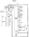
- FIG. 2 is a block diagram illustrating a configuration of a drive system of the hydraulic shovel of FIG. 1 .
- a mechanical power system, a high-pressure hydraulic line, a pilot line, and an electric drive and control system are indicated by a double line, a thick solid line, a broken line, and a thin solid line, respectively.
- a main pump 14 serving as a variable displacement hydraulic pump and a pilot pump 15 serving as a fixed displacement hydraulic pump are connected to the output shaft of an engine 11 serving as a mechanical drive part.
- a control valve 17 is connected to the main pump 14 via a high-pressure hydraulic line 16 and a first pressure discharge part 44.
- an operation apparatus 26 is connected to the pilot pump 15 via a pilot line 25.
- the control valve 17 is a device that controls a hydraulic system in the hydraulic shovel. Hydraulic actuators such as a traveling hydraulic motor 1A (right), a traveling hydraulic motor 1B (left), the boom cylinder 7, the arm cylinder 8, the bucket cylinder 9, and a turning hydraulic motor 21 are connected to the control valve 17 via high-pressure hydraulic lines.
- Hydraulic actuators such as a traveling hydraulic motor 1A (right), a traveling hydraulic motor 1B (left), the boom cylinder 7, the arm cylinder 8, the bucket cylinder 9, and a turning hydraulic motor 21 are connected to the control valve 17 via high-pressure hydraulic lines.
- the operation apparatus 26 includes a lever 26A, a lever 26B, and a pedal 26C.
- the lever 26A, the lever 26B, and the pedal 26C are connected to the control valve 17 and a pressure sensor 29 via hydraulic lines 27 and 28, respectively.
- the pressure sensor 29 is a sensor for detecting what an operator's operation is using the operation apparatus 26.
- the pressure sensor 29, for example, detects the direction of operation and the amount of operation of a lever or pedal of the operation apparatus 26 corresponding to each hydraulic actuator in the form of pressure, and outputs a detected value to a controller 30. What an operation of the operation apparatus 26 is may be detected using a sensor other than a pressure sensor.
- the controller 30 is a controller serving as a main control part that controls the driving of the hydraulic shovel.
- the controller 30 is composed of a processing unit that includes a CPU (Central Processing Unit) and an internal memory, and controls the driving of the hydraulic shovel by causing the CPU to execute a drive control program stored in the internal memory.
- a processing unit that includes a CPU (Central Processing Unit) and an internal memory
- a pressure sensor S1 is a sensor that detects the discharge pressure of the main pump 14, and outputs a detected value to the controller 30.
- a pressure sensor S2L is a sensor that detects the pressure of hydraulic oil on the first port side of the turning hydraulic motor 21, and outputs a detected value to the controller 30.
- a pressure sensor S2R is a sensor that detects the pressure of hydraulic oil on the second port side of the turning hydraulic motor 21, and outputs a detected value to the controller 30.
- a pressure sensor S3 is a sensor that detects the pressure of hydraulic oil of an accumulator part 41 (hereinafter referred to as "accumulator pressure"), and outputs a detected value to the controller 30.
- a pressure sensor S4 is a sensor that detects the pressure of hydraulic oil of the bottom-side oil chamber of the boom cylinder 7, and outputs a detected value to the controller 30.
- the accumulator part 41 is a hydraulic circuit element that stores hydraulic oil in a hydraulic circuit and discharges the stored hydraulic oil as required.
- a first pressure storage part 42 is a hydraulic circuit element that controls a flow of hydraulic oil between the turning hydraulic motor 21 and the accumulator part 41.
- a second pressure storage part 43 is a hydraulic circuit element that controls a flow of hydraulic oil between the control valve 17 and the accumulator part 41.
- the first pressure discharge part 44 is a hydraulic circuit element that controls a flow of hydraulic oil among the main pump 14, the control valve 17, and the accumulator part 41.
- a second pressure discharge part 45 is a hydraulic circuit element that controls a flow of hydraulic oil among the main pump 14, a tank, and the accumulator part 41.
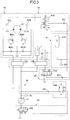
- FIG. 3 illustrates a configuration of a main portion of a hydraulic circuit provided in the hydraulic shovel of FIG. 1 .
- the hydraulic circuit illustrated in FIG. 3 mainly includes a turning control part 40, the accumulator part 41, the first pressure storage part 42, the second pressure storage part 43, the first pressure discharge part 44, and the second pressure discharge part 45.
- the turning control part 40 mainly includes the turning hydraulic motor 21, relief valves 400L and 400R, and check valves 401L and 401R.
- the relief valve 400L is a valve for preventing the pressure of hydraulic oil on the first port 21L side of the turning hydraulic motor 21 from exceeding a predetermined turning relief pressure. Specifically, when the pressure of hydraulic oil on the first port 21L side reaches a predetermined relief pressure, the relief valve 400L discharges the hydraulic oil on the first port 21L side to the tank.
- the relief valve 400R is a valve for preventing the pressure of hydraulic oil on the second port 21R side of the turning hydraulic motor 21 from exceeding a predetermined turning relief pressure. Specifically, when the pressure of hydraulic oil on the second port 21R side reaches a predetermined relief pressure, the relief valve 400R discharges the hydraulic oil on the second port 21R side to the tank.
- the check valve 401L is a valve for preventing the pressure of hydraulic oil on the first port 21L side from falling below a tank pressure. Specifically, when the pressure of hydraulic oil on the first port 21L side decreases to a tank pressure, the check valve 401L supplies hydraulic oil in the tank to the first port 21L side.
- the check valve 401R is a valve for preventing the pressure of hydraulic oil on the second port 21R side from falling below a tank pressure. Specifically, when the pressure of hydraulic oil on the second port 21R side decreases to a tank pressure, the check valve 401R supplies hydraulic oil in the tank to the second port 21R side.
- the accumulator part 41 is a hydraulic circuit element that stores hydraulic oil in the hydraulic circuit and discharges the stored hydraulic oil as required. Specifically, the accumulator part 41 stores hydraulic oil on the braking side (discharge side) of the turning hydraulic motor 21 during turning speed reduction. Furthermore, the accumulator part 41 stores hydraulic oil that the boom cylinder 7 discharges during a boom lowering operation. The accumulator part 41 discharges the stored hydraulic oil to the upstream side (intake side) or the downstream side (discharge side) of the main pump 14 when a hydraulic actuator is operated.
- the accumulator part 41 mainly includes an accumulator 410.
- the accumulator 410 is a device that stores hydraulic oil in the hydraulic circuit, and discharges the stored hydraulic oil as required.
- the accumulator 410 is a spring accumulator that uses the restoring force of a spring.
- the first pressure storage part 42 is a hydraulic circuit element that controls a flow of hydraulic oil between the turning control part 40 (the turning hydraulic motor 21) and the accumulator part 41.
- the first pressure storage part 42 mainly includes a first selector valve 420 and a first check valve 421.
- the first selector valve 420 is a valve that controls a flow of hydraulic oil from the turning control part 40 to the accumulator part 41 at the time of the pressure storing (regenerative) operation of the accumulator part 41.
- the first selector valve 420 is a three-port, three-position selector valve, for which a solenoid valve that switches valve positions in accordance with a control signal from the controller 30 is used.
- a proportional valve using a pilot pressure may be used.
- the first selector valve 420 has a first position, a second position, and a third position as valve positions.
- parenthesized numbers indicate the numbers of valve positions. The same is the case with other selector valves.
- the first position is a valve position that causes the first port 21L to communicate with the accumulator part 41.
- the second position is a valve position that interrupts the communication between the turning control part 40 and the accumulator part 41.
- the third position is a valve position that causes the second port 21R to communicate with the accumulator part 41.
- the first check valve 421 is a valve that prevents hydraulic oil from flowing from the accumulator part 41 to the turning control part 40.
- the second pressure storage part 43 is a hydraulic circuit element that controls a flow of hydraulic oil between the control valve 17 and the accumulator part 41.
- the second pressure storage part 43 is disposed among a boom cylinder flow control valve 17B, the tank, and the accumulator part 41, and mainly includes a second selector valve 430 and a second check valve 431.
- the boom cylinder flow control valve 17B may be one or more of the other flow control valves such as an arm cylinder flow control valve.
- the second selector valve 430 is a valve that controls a flow of hydraulic oil from a hydraulic actuator to the accumulator part 41 at the time of the pressure storing (regenerative) operation of the accumulator part 41.
- the second selector valve 430 is a three-port, two-position selector valve, for which a solenoid valve that switches valve positions in accordance with a control signal from the controller 30 is used.
- a proportional valve using a pilot pressure may be used.
- the second selector valve 430 has a first position and a second position as valve positions.
- the first position is a valve position that causes the discharge port of the boom cylinder flow control valve 17B to communicate with the tank and interrupts the communication between the discharge port of the boom cylinder flow control valve 17B and the accumulator part 41.
- the second position is a valve position that causes the discharge port of the boom cylinder flow control valve 17B to communicate with the accumulator part 41 and interrupts the communication between the discharge port of the boom cylinder flow control valve 17B and the tank.
- the second check valve 431 is a valve that prevents hydraulic oil from flowing from the accumulator part 41 to the second selector valve 430.
- the first pressure discharge part 44 is a hydraulic circuit element that controls a flow of hydraulic oil among the main pump 14, the control valve 17, and the accumulator part 41.
- the first pressure discharge part 44 mainly includes a third selector valve 440 and a third check valve 441.
- the third selector valve 440 is a valve that controls a flow of hydraulic oil from the accumulator part 41 to a junction on the downstream side of the main pump 14 at the time of the pressure discharge (power running) operation of the accumulator part 41.
- the third selector valve 440 is a two-port, two-position selector valve, for which a solenoid valve that switches valve positions in accordance with a control signal from the controller 30 is used. Alternatively, a proportional valve using a pilot pressure may be used.
- the third selector valve 440 has a first position and a second position as valve positions.
- the first position is a valve position that interrupts the communication between the junction on the downstream side of the main pump 14 and the accumulator part 41.
- the second position is a valve position that causes the junction on the downstream side of the main pump 14 to communicate with the accumulator part 41.
- the third check valve 441 is a valve that prevents hydraulic oil from flowing from the main pump 14 to the accumulator part 41.
- the second pressure discharge part 45 is a hydraulic circuit element that controls a flow of hydraulic oil among the tank, the main pump 14, and the accumulator part 41. According to this embodiment, the second pressure discharge part 45 mainly includes a fourth selector valve 450.
- the fourth selector valve 450 is a valve that controls a flow of hydraulic oil from the accumulator part 41 to a junction on the upstream side of the main pump 14 at the time of the pressure discharge (power running) operation of the accumulator part 41.
- the fourth selector valve 450 is a three-port, two-position selector valve, for which a solenoid valve that switches valve positions in accordance with a control signal from the controller 30 is used. Alternatively, a proportional valve using a pilot pressure may be used.
- the fourth selector valve 450 has a first position and a second position as valve positions.
- the first position is a valve position that causes the main pump 14 to communicate with the tank and interrupts the communication between the main pump 14 and the accumulator part 41.
- the second position is a valve position that interrupts the communication between the main pump 14 and the tank and causes the main pump 14 to communicate with the accumulator part 41.
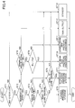
- FIG. 4 is a flowchart illustrating a flow of the pressure storing and pressure discharge operation, and the controller 30 repeatedly executes this pressure storing and pressure discharge operation at predetermined intervals.
- FIG. 5 is a correspondence table illustrating the correspondence between the state of the hydraulic circuit of FIG. 3 and the state of the selector valves.
- the controller 30 determines whether a hydraulic actuator has been operated based on the outputs of various sensors for detecting the condition of the shovel (step ST1). According to this embodiment, the controller 30 determines whether a hydraulic actuator has been operated based on the outputs of the pressure sensor 29.
- the controller 30 determines whether the operation is a regenerative operation or a power running operation (step ST2). According to this embodiment, the controller 30 determines, based on the outputs of the pressure sensor 29, whether a regenerative operation such as a turning speed reduction operation or a boom lowering operation has been performed or a power running operation such as a turning speed increasing operation or a boom raising operation has been performed.
- the controller 30 determines whether the regenerative operation is a turning speed reduction operation or a regenerative operation other than that (step ST3).
- the controller 30 determines whether the accumulator part 41 is ready to store pressure (step ST4). According to this embodiment, the controller 30 determines whether the accumulator part 41 is ready to store pressure based on a pressure Pso on the braking side (discharge side) of the turning hydraulic motor 21, output by the pressure sensor S2L or the pressure sensor S2R, and an accumulator pressure Pa output by the pressure sensor S3.
- the controller 30 determines that the accumulator part 41 is ready to store pressure if the pressure Pso exceeds the accumulator pressure Pa, and determines that the accumulator part 41 is not ready to store pressure if the pressure Pso is less than or equal to the accumulator pressure Pa.
- the controller 30 sets the state of the hydraulic circuit to a state of "turning pressure storage" (step ST5).
- the controller 30 sets the first selector valve 420 to the first position or third position so as to cause the turning control part 40 to communicate with the accumulator part 41 via the first pressure storage part 42. Furthermore, the controller 30 sets the second selector valve 430 to the first position so as to cause the discharge port of the boom cylinder flow control valve 17B to communicate with the tank and interrupt the communication between the discharge port of the boom cylinder flow control valve 17B and the accumulator part 41. Furthermore, the controller 30 sets the third selector valve 440 to the first position so as to interrupt the communication between the junction on the downstream side of the main pump 14 and the accumulator part 41. Furthermore, the controller 30 sets the fourth selector valve 450 to the first position so as to cause the main pump 14 to communicate with the tank and interrupt the communication between the main pump 14 and the accumulator part 41.
- the controller 30 determines whether the accumulator part 41 is ready to store pressure (step ST6). According to this embodiment, the controller 30 determines whether the accumulator part 41 is ready to store pressure based on a pressure Pbb of the bottom-side oil chamber of the boom cylinder 7, output by the pressure sensor S4, and the accumulator pressure Pa output by the pressure sensor S3.
- the controller 30 determines that the accumulator part 41 is ready to store pressure if the pressure Pbb exceeds the accumulator pressure Pa, and determines that the accumulator part 41 is not ready to store pressure if the pressure Pbb is less than or equal to the accumulator pressure Pa.
- the controller 30 sets the state of the hydraulic system to a state of "hydraulic cylinder pressure storage” (step ST7).
- the controller 30 sets the state of the hydraulic circuit to the "hydraulic cylinder pressure storage" state in response to determining that the regenerative operation is a boom lowering operation.
- the controller 30 sets the first selector valve 420 to the second position so as to interrupt the communication between the turning control part 40 and the accumulator part 41 via the first pressure storage part 42. Furthermore, the controller 30 sets the second selector valve 430 to the second position so as to cause the discharge port of the boom cylinder flow control valve 17B to communicate with the accumulator part 41 and interrupt the communication between the discharge port of the boom cylinder flow control valve 17B and the tank.
- the bottom-side hydraulic oil of the boom cylinder 7 flows to the accumulator part 41 via the second pressure storage part 43 so as to be stored in the accumulator 410. Furthermore, because each of the first selector valve 420, the third selector valve 440, and the fourth selector valve 450 is closed relative to the accumulator part 41, the bottom-side hydraulic oil of the boom cylinder 7 is prevented from flowing into locations other than the accumulator part 41.
- the controller 30 determines whether the pressure storage condition of the accumulator part 41 is appropriate for pressure discharge (step ST8). According to this embodiment, the controller 30 determines whether the accumulator pressure Pa is less than a predetermined pressure Pa0 based on the output of the pressure sensor S3.
- the controller 30 determines whether the accumulator pressure Pa is less than a discharge pressure Pp that is the output of the pressure sensor S1 (step ST9). According to this embodiment, in response to determining that the accumulator pressure Pa is more than or equal to the predetermined pressure Pa0, the controller determines whether the accumulator pressure Pa is less than the discharge pressure Pp.
- the controller 30 sets the state of the hydraulic circuit to a state of "upstream side pressure discharge” (step ST10).
- the controller 30 sets the first selector valve 420 to the second position so as to interrupt the communication between the turning control part 40 and the accumulator part 41 via the first pressure storage part 42. Furthermore, the controller 30 sets the second selector valve 430 to the first position so as to cause the discharge port of the boom cylinder flow control valve 17B to communicate with the tank and interrupt the communication between the discharge port of the boom cylinder flow control valve 17B and the accumulator part 41. Furthermore, the controller 30 sets the third selector valve 440 to the first position so as to interrupt the communication between the junction on the downstream side of the main pump 14 and the accumulator part 41. Furthermore, the controller 30 sets the fourth selector valve 450 to the second position so as to interrupt the communication between the main pump 14 and the tank and cause the main pump 14 to communicate with the accumulator part 41.
- the controller 30 sets the state of the hydraulic circuit to a state of "downstream side pressure discharge" (step ST11).
- the controller 30 sets the third selector valve 440 to the second position so as to cause the junction on the downstream side of the main pump 14 to communicate with the accumulator part 41. Furthermore, the controller 30 sets the fourth selector valve 450 to the first position so as to cause the main pump 14 to communicate with the tank and interrupt the communication between the main pump 14 and the accumulator part 41.
- the controller 30 sets the state of the hydraulic circuit to a state of "tank supply” (step ST12), and prevents hydraulic oil from being discharged from the accumulator part 41.
- the controller 30 sets the third selector valve 440 to the first position so as to interrupt the communication between the junction on the downstream side of the main pump 14 and the accumulator part 41. Furthermore, the controller 30 sets the fourth selector valve 450 to the first position so as to cause the main pump 14 to communicate with the tank and interrupt the communication between the main pump 14 and the accumulator part 41.
- the main pump 14 supplies hydraulic oil drawn in from the tank to a hydraulic actuator in operation. Furthermore, because each of the first selector valve 420, the second selector valve 430, the third selector valve 440, and the fourth selector valve 450 is closed relative to the accumulator part 41, no hydraulic oil is stored in or discharged from the accumulator part 41.
- the first selector valve 420 and the second selector valve 430 may be switched so as to allow the accumulator part 41 to store hydraulic oil.
- the controller 30 sets the state of the hydraulic circuit to a state of "standby" (step ST13).
- the states of the first selector valve 420, the second selector valve 430, the third selector valve 440, and the fourth selector valve 450 are the same as the states at the time of "tank supply.”
- the "standby" state no hydraulic oil is stored in or discharged from the accumulator part 41.
- the controller 30 sets the state of the hydraulic circuit to the "standby" state (step ST13). In this case, because the first selector valve 420 is at the second position, hydraulic oil on the braking side (discharge side) of the turning hydraulic motor 21 is discharged to the tank via the relief valve 400L or the relief valve 400R.
- the controller 30 sets the state of the hydraulic circuit to the "standby" state (step ST13). In this case, because the second selector valve 430 is at the first position, hydraulic oil in the bottom-side oil chamber of the boom cylinder 7 is discharged to the tank via the boom cylinder flow control valve 17B and the second selector valve 430.
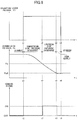
- FIG. 6 illustrates temporal transitions of an operation lever pressure, an accumulator pressure, and control signals for the third selector valve 440 and the fourth selector valve 450 at the time of the pressure discharge of the accumulator 410.
- the transition of an operation lever pressure Pi at the top of FIG. 6 represents the transition of a pilot pressure that varies in accordance with the operation of a boom operation lever in a boom raising direction.
- the transition of the accumulator pressure Pa in the middle of FIG. 6 represents the transition of the detected value of the pressure sensor S3.
- the transitions of control signals at the bottom of FIG. 6 represent the transition of a control signal for the third selector valve 440 (solid line) and the transition of a control signal for the fourth selector valve 450 (dotted line).
- the controller 30 determines whether the accumulator pressure Pa is more than or equal to the predetermined pressure Pa0.
- the controller 30 causes hydraulic oil in the accumulator 410 to be discharged.
- the controller 30 causes the discharge of hydraulic oil in the accumulator 410 to be started at time t1.
- the controller 30 in response to determining that the accumulator pressure Pa is more than or equal to the discharge pressure Pp of the main pump 14 at time t1, the controller 30 sets the state of the hydraulic circuit to the "downstream side pressure discharge" state.
- the discharge pressure Pp which is actually a variable value that varies in accordance with a load, is assumed to be a constant value for simplification of description.
- the controller 30 sets the level of the control signal for the third selector valve 440 to ON level (a level for implementing the second position) at time t1 as illustrated at the bottom of FIG. 6 .
- the third selector valve 440 is set to the second position so as to cause the junction on the downstream side of the main pump 14 to communicate with the accumulator 410.
- the bottom-side oil chamber of the boom cylinder 7 directly receives hydraulic oil discharged from the accumulator 410. That is, the bottom-side oil chamber of the boom cylinder 7 receives hydraulic oil discharged from the accumulator 410 without intervention of the main pump 14 so as to expand to raise the boom 4.
- the accumulator 410 discharges hydraulic oil in the accumulator 410 to the junction on the downstream side of the main pump 14. Therefore, the accumulator pressure Pa decreases over time so as to fall below the discharge pressure Pp at time t2 as illustrated in the middle of FIG. 6 .
- the controller 30 In response to determining at time t2 that the accumulator pressure Pa is less than the discharge pressure Pp, the controller 30 sets the state of the hydraulic circuit to the "upstream side pressure discharge" state.
- the controller 30 sets the level of the control signal for the third selector valve 440 to OFF level (a level for implementing the first position) and sets the level of the control signal for the fourth selector valve 450 to ON level as illustrated at the bottom of FIG. 6 .
- the third selector valve 440 is set to the first position so as to interrupt the communication between the junction on the downstream side of the main pump 14 and the accumulator 410.
- the fourth selector valve 450 is set to the second position so as to cause the junction on the upstream side of the main pump 14 to communicate with the accumulator 410.
- the bottom-side oil chamber of the boom cylinder 7 indirectly receives hydraulic oil discharged from the accumulator 410. That is, the bottom-side oil chamber of the boom cylinder 7 receives hydraulic oil discharged by the main pump 14 that has drawn in hydraulic oil discharged from the accumulator 410, so as to expand to continue raising the boom 4.
- the accumulator 410 stops discharging hydraulic oil in the accumulator 410 to the junction on the downstream side of the main pump 14, and discharges hydraulic oil in the accumulator 410 to the junction on the upstream side of the main pump 14. Thereafter, the accumulator pressure Pa continues to decrease over time so as to fall below the predetermined pressure Pa0 at time t3 as illustrated in the middle of FIG. 6 .
- the controller 30 In response to determining at time t3 that the accumulator pressure Pa is less than the predetermined pressure Pa0, the controller 30 sets the state of the hydraulic circuit to the "tank supply" state.
- the controller 30 sets the level of the control signal for the fourth selector valve 450 to OFF level as illustrated at the bottom of FIG. 6 .
- the third selector valve 440 is set to the first position so as to interrupt the communication between the junction on the upstream side of the main pump 14 and the accumulator 410. That is, the controller 30 stops discharging any hydraulic oil in the accumulator 410. Then, the bottom-side oil chamber of the boom cylinder 7 receives hydraulic oil discharged by the main pump 14 that has drawn in hydraulic oil from the tank, so as to expand to further continue raising the boom 4.
- the boom cylinder flow control valve 17B interrupts the communication between the main pump 14 and the boom cylinder 7 so as to stop expansion of the bottom-side oil chamber of the boom cylinder 7.
- the above-described hydraulic circuit by the above-described configuration, it is possible to store hydraulic oil with regenerable energy discharged from a hydraulic actuator in the accumulator 410 and reuse the stored hydraulic oil. Furthermore, according to the above-described hydraulic circuit, it is made possible to use hydraulic oil in the accumulator part 41 not only when the accumulator pressure Pa is more than or equal to the discharge pressure Pp but also when the accumulator pressure Pa is less than the discharge pressure Pp. Therefore, according to the above-described circuit, it is possible to more efficiently use hydraulic energy stored in the accumulator part 41.
- hydraulic oil is prevented from flowing into the accumulator part 41 when a power running operation is to be performed.
- hydraulic oil may be caused to flow into the accumulator part.
- the controller 30 executes the alternative of turning pressure storage or hydraulic cylinder pressure storage.
- the controller 30 may execute turning pressure storage and hydraulic cylinder pressure storage simultaneously.
- the controller 30 may set the second selector valve 430 to the second position while setting the first selector valve 420 to the first position or the third position.
- a hydraulic actuator is driven using hydraulic oil discharged by the main pump 14 or using both hydraulic oil discharged by the main pump 14 and hydraulic oil stored in the accumulator part 41.
- hydraulic oil it is also possible to allow hydraulic oil to flow from the main pump 14 to the accumulator part 41 by omitting the third check valve 441, so that hydraulic oil discharged by the main pump 14 may be stored in the accumulator part 41.
- a hydraulic actuator it is also possible to allow a hydraulic actuator to be driven using only hydraulic oil stored in the accumulator part 41.
- hydraulic oil from the accumulator part 41 is caused to merge at the junction on the upstream side or the junction on the downstream side of the main pump 14.
- the present invention is not limited to this configuration.
- the above-described hydraulic circuit may have a configuration that allows the accumulator part 41 to discharge hydraulic oil directly to a hydraulic actuator instead of the configuration of causing hydraulic oil from the accumulator part 41 to merge at the junction on the downstream side of the main pump 14.
- the above-described hydraulic circuit may be configured to cause hydraulic oil from the accumulator part 41 to merge at the junction on the upstream side of the main pump 14.
- the main pump 14 it is made possible to discharge hydraulic oil from the accumulator part 41 at the junction on the upstream side of the main pump 14. Therefore, compared with the case of drawing in relatively low-pressure hydraulic oil from the tank and discharging the drawn-in hydraulic oil, it is possible for the main pump 14 to reduce absorbed horsepower (a torque necessary to discharge a predetermined amount of hydraulic oil) and promote energy saving. Furthermore, it is possible for the main pump 14 to increase the responsiveness of discharge quantity control.
- the accumulator part 41 includes the single accumulator 410.
- the present invention is not limited to this configuration.
- the accumulator part 41 may include two or more accumulators connected in parallel.
- each accumulator may have any capacity.
- the accumulators may have the same capacity or capacities different from each other.
- the accumulators may have different maximum discharge pressures in order to make it possible to select an accumulator as a supply source or a storage destination of hydraulic oil from among the accumulators that are different in maximum discharge pressure in accordance with a required discharge pressure.
- the "maximum discharge pressure” is a maximum pressure dischargeable by an accumulator, and is a pressure determined by the maximum pressure of the accumulator at the time of a pressure storing (regenerative) operation.
- the accumulators may store or discharge pressure at respective different times. Two or more of the accumulators may store or discharge pressure at respective times that overlap or coincide with each other.
- FIG. 7 illustrates a configuration of a main portion of another hydraulic circuit provided in the hydraulic shovel of FIG. 1 .
- the hydraulic circuit of FIG. 7 is different from the hydraulic circuit of FIG. 3 in including an accumulator selector valve 411, but otherwise is the same as the hydraulic circuit of FIG. 3 . Therefore, a description of common points is omitted, and a description is given in detail of differences.
- the accumulator selector valve 411 is a valve that controls the communication and interruption between the accumulator 410 and other parts of the hydraulic circuit.
- the accumulator selector valve 411 is a two-port, two-position selector valve, for which a solenoid valve that switches valve positions in accordance with a control signal from the controller 30 is used. Alternatively, a proportional valve using a pilot pressure may be used.
- the accumulator selector valve 411 has a first position and a second position as valve positions. The first position is a valve position that interrupts the communication between the accumulator 410 and other parts of the hydraulic circuit. The second position is a valve position that causes the accumulator 410 to communicate with other parts of the hydraulic circuit.
- This configuration makes it possible for the controller 30 to cause hydraulic oil flowing out from the turning control part 40 through the first selector valve 420 to merge with the junction on the upstream side or the downstream side of the main pump 14 without being stored in the accumulator 410.
- the controller 30 sets one of the third selector valve 440 and the fourth selector valve 450 to the second position. As a result, it is possible for the controller 30 to cause hydraulic oil flowing out from the braking side of the turning hydraulic motor 21 to merge with the junction on the upstream side or the downstream side of the main pump 14.
- controller 30 it is possible for the controller 30 to cause hydraulic oil flowing out from the boom cylinder flow control valve 17B through the second selector valve 430 to merge with the junction on the upstream side or the downstream side of the main pump 14 without being stored in the accumulator 410.
- the controller 30 sets one of the third selector valve 440 and the fourth selector valve 450 to the second position. As a result, it is possible for the controller 30 to cause hydraulic oil flowing out from the bottom-side oil chamber of the boom cylinder 7 to merge with the junction on the upstream side or the downstream side of the main pump 14.
- FIG. 8 is a flowchart illustrating a flow of the pressure storing and pressure discharge operation in the hydraulic circuit of FIG. 7 .
- FIG. 9 is a correspondence table illustrating the correspondence between the state of the hydraulic circuit of FIG. 7 and the state of the selector valves.
- FIG. 8 is different from the flowchart of FIG. 4 in the processes in the case when it is determined that the accumulator part 41 is not ready to store pressure (the processes in the case of NO at step ST4 and in the case of NO at step ST6), but otherwise is the same as the flowchart of FIG. 4 . Therefore, a graphical representation and description of a common portion is omitted.
- the controller 30 determines whether the accumulator part 41 is ready to store pressure (step ST4).
- the controller 30 determines whether a hydraulic actuator is being driven (step ST41). According to this embodiment, the controller 30 determines, based on the output of the pressure sensor 29, whether the boom 4 is being operated, that is, whether the boom cylinder 7 is being driven.
- the controller 30 determines whether the pressure Pso on the braking side (discharge side) of the turning hydraulic motor 21 is more than or equal to the discharge pressure Pp (step ST42).
- the controller 30 sets the state of the hydraulic circuit to a state of "turning discharge flow upstream side regeneration" (step ST43).
- the controller 30 sets the first selector valve 420 to the first position or the third position, sets the fourth selector valve 450 to the second position, and sets the accumulator selector valve 411 to the first position.
- the controller 30 causes the turning control part 40 to communicate with the junction on the upstream side of the main pump 14.
- the controller 30 sets the second selector valve 430 to the first position so as to cause the discharge port of the boom cylinder flow control valve 17B to communicate with the tank.
- the controller 30 sets the third selector valve 440 to the first position so as to interrupt the communication between the turning control part 40 and the junction on the downstream side of the main pump 14.
- the controller 30 sets the state of the hydraulic circuit to a state of "turning discharge flow downstream side regeneration" (step ST44).
- the controller 30 sets the first selector valve 420 to the first position or the third position, sets the third selector valve 440 to the second position, and sets the accumulator selector valve 411 to the first position.
- the controller 30 causes the turning control part 40 to communicate with the junction on the downstream side of the main pump 14.
- the controller 30 sets the second selector valve 430 to the first position so as to cause the discharge port of the boom cylinder flow control valve 17B to communicate with the tank.
- the controller 30 sets the fourth selector valve 450 to the first position so as to interrupt the communication between the turning control part 40 and the junction on the upstream side of the main pump 14.
- the controller 30 sets the state of the hydraulic circuit to the "standby" state (step ST13). In this case, because the first selector valve 420 is at the second position, hydraulic oil on the braking side (discharge side) of the turning hydraulic motor 21 is discharged to the tank via the relief valve 400L or the relief valve 400R.
- the controller 30 determines whether the accumulator part 41 is ready to store pressure (step ST6). According to this embodiment, in response to determining that the regenerative operation is a boom lowering operation, the controller 30 determines whether the accumulator part 41 is ready to store pressure.
- step ST6 the controller 30 determines whether a turning speed increasing operation is being performed.
- the controller 30 determines whether the pressure Pbb of the bottom-side oil chamber of the boom cylinder 7 is more than or equal to the discharge pressure Pp (step ST62).
- the controller 30 sets the state of the hydraulic circuit to a state of "hydraulic cylinder discharge flow upstream side regeneration" (step ST63).
- the controller 30 sets the second selector valve 430 to the second position, sets the fourth selector valve 450 to the second position, and sets the accumulator selector valve 411 to the first position.
- the controller 30 causes the bottom-side oil chamber of the boom cylinder 7 to communicate with the junction on the upstream side of the main pump 14.
- the controller 30 sets the first selector valve 420 to the second position so as to interrupt the communication between the turning control part 40 and the first pressure storage part 42.
- the controller 30 sets the third selector valve 440 to the first position so as to interrupt the communication between the bottom-side oil chamber of the boom cylinder 7 and the junction on the downstream side of the main pump 14.
- hydraulic oil discharged from the bottom-side oil chamber of the boom cylinder 7 is discharged (regenerated) at the junction on the upstream side of the main pump 14 through the second pressure storage part 43 and the second pressure discharge part 45.
- the controller 30 sets the state of the hydraulic circuit to a state of "hydraulic cylinder discharge flow downstream side regeneration" (step ST64).
- the controller 30 sets the second selector valve 430 to the second position, sets the third selector valve 440 to the second position, and sets the accumulator selector valve 411 to the first position.
- the controller 30 causes the bottom-side oil chamber of the boom cylinder 7 to communicate with the junction on the downstream side of the main pump 14.
- the controller 30 sets the first selector valve 420 to the second position so as to interrupt the communication between the turning control part 40 and the first pressure storage part 42.
- the controller 30 sets the fourth selector valve 450 to the first position so as to interrupt the communication between the bottom-side oil chamber of the boom cylinder 7 and the junction on the upstream side of the main pump 14.
- hydraulic oil discharged from the bottom-side oil chamber of the boom cylinder 7 is discharged (regenerated) at the junction on the downstream side of the main pump 14 through the second pressure storage part 43 and the first pressure discharge part 44.
- step ST13 the controller 30 sets the state of the hydraulic circuit to the "standby" state (step ST13). In this case, because the second selector valve 430 is at the first position, the hydraulic oil of the bottom-side oil chamber of the boom cylinder 7 is discharged to the tank via the boom cylinder flow control valve 17B and the second selector valve 430.
- the hydraulic circuit of FIG. 7 produces the effect that hydraulic oil with regenerable energy discharged from a hydraulic actuator may be reused without being stored in the accumulator 410, in addition to the effect by the hydraulic circuit of FIG. 3 .
- the accumulator 410 stores hydraulic oil from the turning hydraulic motor 21 and the boom cylinder 7.
- the present invention is not limited to this configuration.
- the accumulator 410 may be configured to store hydraulic oil from the turning hydraulic motor 21 and other hydraulic actuators.
- hydraulic oil discharged from the hydraulic actuators that have performed regenerative operations may be merged at the junction on the upstream side or the downstream side of the main pump 14 without being stored in the accumulator 410, so as to be supplied to the hydraulic actuators that have performed power running operations.
- the accumulator 410 may also be configured to store only hydraulic oil from the turning hydraulic motor 21.
- the second pressure storage part 43 may be omitted.
- the accumulator 410 may also be configured to store only hydraulic oil from one or more hydraulic actuators other than the turning hydraulic motor 21.
- the first pressure storage part 42 may be omitted, and the turning hydraulic motor 21 may be an electric motor.
- FIG. 10 is a block diagram illustrating another configuration of the drive system of the hydraulic shovel of FIG. 1 .
- a mechanical power system, a high-pressure hydraulic line, a pilot line, and an electric drive and control system are indicated by a double line, a thick solid line, a broken line, and a thin solid line, respectively.
- the main pump 14 serving as a variable displacement hydraulic pump, the pilot pump 15 serving as a fixed displacement hydraulic pump, and a pump motor 35 as a variable displacement hydraulic pump motor are connected to the output shaft of the engine 11 serving as a mechanical drive part.
- the control valve 17 is connected to the main pump 14 via the high-pressure hydraulic line 16.
- the operation apparatus 26 is connected to the pilot pump 15 via the pilot line 25.
- the control valve 17 is a device that controls a hydraulic system in the hydraulic shovel. Hydraulic actuators such as the traveling hydraulic motor 1A (right), the traveling hydraulic motor 1B (left), the boom cylinder 7, the arm cylinder 8, the bucket cylinder 9, and the turning hydraulic motor 21 are connected to the control valve 17 via high-pressure hydraulic lines.
- the operation apparatus 26 includes the lever 26A, the lever 26B, and the pedal 26C.
- the lever 26A, the lever 26B, and the pedal 26C are connected to the control valve 17 and the pressure sensor 29 via the hydraulic lines 27 and 28, respectively.
- the pressure sensor 29 is a sensor for detecting what an operator's operation is using the operation apparatus 26.
- the pressure sensor 29, for example, detects the direction of operation and the amount of operation of a lever or pedal of the operation apparatus 26 corresponding to each hydraulic actuator in the form of pressure, and outputs a detected value to a controller 30. What an operation of the operation apparatus 26 is may be detected using a sensor other than a pressure sensor.
- the controller 30 is a controller serving as a main control part that controls the driving of the hydraulic shovel.
- the controller 30 is composed of a processing unit that includes a CPU (Central Processing Unit) and an internal memory, and controls the driving of the hydraulic shovel by causing the CPU to execute a drive control program stored in the internal memory.
- a processing unit that includes a CPU (Central Processing Unit) and an internal memory
- the pressure sensor S1 is a sensor that detects the discharge pressure of the main pump 14, and outputs a detected value to the controller 30.
- the pressure sensor S2L is a sensor that detects the pressure of hydraulic oil on the first port side of the turning hydraulic motor 21, and outputs a detected value to the controller 30.
- the pressure sensor S2R is a sensor that detects the pressure of hydraulic oil on the second port side of the turning hydraulic motor 21, and outputs a detected value to the controller 30.
- the pressure sensor S3 is a sensor that detects the pressure of hydraulic oil of the accumulator part 41 (hereinafter referred to as "accumulator pressure"), and outputs a detected value to the controller 30.
- the pressure sensor S4 is a sensor that detects the pressure of hydraulic oil of the bottom-side oil chamber of the boom cylinder 7, and outputs a detected value to the controller 30.
- the accumulator part 41 is a hydraulic circuit element that stores hydraulic oil in a hydraulic circuit and discharges the stored hydraulic oil as required.
- the first pressure storage part 42 is a hydraulic circuit element that controls a flow of hydraulic oil between the turning hydraulic motor 21 and the accumulator part 41.
- the second pressure storage part 43 is a hydraulic circuit element that controls a flow of hydraulic oil between the control valve 17 and the accumulator part 41.
- a first pressure discharge part 44A is a hydraulic circuit element that controls a flow of hydraulic oil among the main pump 14, the control valve 17, and the accumulator part 41.
- a second pressure discharge part 45A is a hydraulic circuit element that controls a flow of hydraulic oil among the main pump 14, the tank, and the accumulator part 41.
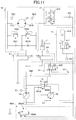
- FIG. 11 illustrates a configuration of a main portion of the hydraulic circuit provided in the hydraulic shovel of FIG. 1 .
- the hydraulic circuit illustrated in FIG. 11 mainly includes the turning control part 40, the accumulator part 41, the first pressure storage part 42, the second pressure storage part 43, the first pressure discharge part 44A, and the second pressure discharge part 45A.
- the turning control part 40 mainly includes the turning hydraulic motor 21, the relief valves 400L and 400R, and the check valves 401L and 401R.
- the relief valve 400L is a valve for preventing the pressure of hydraulic oil on the first port 21L side of the turning hydraulic motor 21 from exceeding a predetermined turning relief pressure. Specifically, when the pressure of hydraulic oil on the first port 21L side reaches a predetermined relief pressure, the relief valve 400L discharges the hydraulic oil on the first port 21L side to the tank.
- the relief valve 400R is a valve for preventing the pressure of hydraulic oil on the second port 21R side of the turning hydraulic motor 21 from exceeding a predetermined turning relief pressure. Specifically, when the pressure of hydraulic oil on the second port 21R side reaches a predetermined relief pressure, the relief valve 400R discharges the hydraulic oil on the second port 21R side to the tank.
- the check valve 401L is a valve for preventing the pressure of hydraulic oil on the first port 21L side from falling below a tank pressure. Specifically, when the pressure of hydraulic oil on the first port 21L side decreases to a tank pressure, the check valve 401L supplies hydraulic oil in the tank to the first port 21L side.
- the check valve 401R is a valve for preventing the pressure of hydraulic oil on the second port 21R side from falling below a tank pressure. Specifically, when the pressure of hydraulic oil on the second port 21R side decreases to a tank pressure, the check valve 401R supplies hydraulic oil in the tank to the second port 21R side.
- the accumulator part 41 is a hydraulic circuit element that stores hydraulic oil in the hydraulic circuit and discharges the stored hydraulic oil as required. Specifically, the accumulator part 41 stores hydraulic oil on the braking side (discharge side) of the turning hydraulic motor 21 during turning speed reduction. Furthermore, the accumulator part 41 stores hydraulic oil that the boom cylinder 7 discharges during a boom lowering operation. The accumulator part 41 discharges the stored hydraulic oil to the upstream side (intake side) or the downstream side (discharge side) of the main pump 14 when a hydraulic actuator is operated.
- the accumulator part 41 mainly includes the accumulator 410 and the accumulator selector valve 411.
- the accumulator 410 is a device that stores hydraulic oil in the hydraulic circuit, and discharges the stored hydraulic oil as required. According to this embodiment, the accumulator 410 is a spring accumulator that uses the restoring force of a spring.
- the accumulator selector valve 411 is a valve that controls a flow of hydraulic oil between the accumulator 410 and other parts of the hydraulic circuit.
- the accumulator selector valve 411 is a two-port, two-position selector valve, for which a solenoid valve that switches valve positions in accordance with a control signal from the controller 30 is used. Alternatively, a proportional valve using a pilot pressure may be used.
- the accumulator selector valve 411 has a first position and a second position as valve positions. In the drawing, parenthesized numbers indicate the numbers of valve positions. The same is the case with other selector valves.
- the first position is a valve position that interrupts the communication between the accumulator 410 and other parts of the hydraulic circuit.
- the second position is a valve position that causes the accumulator 410 to communicate with other parts of the hydraulic circuit.
- the accumulator selector valve 411 may be omitted.
- the first pressure storage part 42 is a hydraulic circuit element that controls a flow of hydraulic oil between the turning control part 40 (the turning hydraulic motor 21) and the accumulator part 41.
- the first pressure storage part 42 mainly includes the first selector valve 420 and the first check valve 421.
- the first selector valve 420 is a valve that controls a flow of hydraulic oil from the turning control part 40 to the accumulator part 41 at the time of the pressure storing (regenerative) operation of the accumulator part 41.
- the first selector valve 420 is a three-port, three-position selector valve, for which a solenoid valve that switches valve positions in accordance with a control signal from the controller 30 is used.
- a proportional valve using a pilot pressure may be used.
- the first selector valve 420 has a first position, a second position, and a third position as valve positions.
- the first position is a valve position that causes the first port 21L to communicate with the accumulator part 41.
- the second position is a valve position that interrupts the communication between the turning control part 40 and the accumulator part 41.
- the third position is a valve position that causes the second port 21R to communicate with the accumulator part 41.
- the first check valve 421 is a valve that prevents hydraulic oil from flowing from the accumulator part 41 to the turning control part 40.
- the second pressure storage part 43 is a hydraulic circuit element that controls a flow of hydraulic oil between the control valve 17 and the accumulator part 41.
- the second pressure storage part 43 is disposed among the boom cylinder flow control valve 17B, the tank, and the accumulator part 41, and mainly includes the second selector valve 430 and the second check valve 431.
- the boom cylinder flow control valve 17B may be one or more of the other flow control valves such as an arm cylinder flow control valve.
- the second selector valve 430 is a valve that controls a flow of hydraulic oil from a hydraulic actuator to the accumulator part 41 at the time of the pressure storing (regenerative) operation of the accumulator part 41.
- the second selector valve 430 is a three-port, two-position selector valve, for which a solenoid valve that switches valve positions in accordance with a control signal from the controller 30 is used.
- a proportional valve using a pilot pressure may be used.
- the second selector valve 430 has a first position and a second position as valve positions.
- the first position is a valve position that causes the discharge port of the boom cylinder flow control valve 17B to communicate with the tank and interrupts the communication between the discharge port of the boom cylinder flow control valve 17B and the accumulator part 41.
- the second position is a valve position that causes the discharge port of the boom cylinder flow control valve 17B to communicate with the accumulator part 41 and interrupts the communication between the discharge port of the boom cylinder flow control valve 17B and the tank.
- the second check valve 431 is a valve that prevents hydraulic oil from flowing from the accumulator part 41 to the second selector valve 430.
- the first pressure discharge part 44A is a hydraulic circuit element that controls a flow of hydraulic oil among the main pump 14, the control valve 17, and the accumulator part 41.
- the first pressure discharge part 44A mainly includes the pump motor 35, a third selector valve 440A and a third check valve 441A.
- the pump motor 35 is a variable displacement hydraulic pump motor whose discharge flow rate varies in accordance with a control signal from the controller 30, and the minimum flow rate of the pump motor 35 can be set to be extremely small, preferably, to substantially zero.
- the rotating shaft of the pump motor 35 is connected to the drive shaft of the engine 11.
- the pump motor 35 is connected to the main pump 14 so that rotation may be transmitted between the pump motor 35 and the main pump 14 via the drive shaft of the engine 11.
- the rotating shaft of the pump motor 35 is connected to the rotating shaft of the main pump 14 via the drive shaft of the engine 11.
- the rotating shaft of the pump motor 35 may be connected to the drive shaft of the engine 11 via a clutch mechanism, a continuously variable transmission mechanism (such as an infinitely variable transmission), or the like.
- the pump motor 35 does not have to be one whose minimum flow rate can be set to substantially zero.
- a makeup circuit for preventing cavitation in the pump motor 35 during its stoppage is provided on the upstream side of the pump motor 35.
- the rotating shaft of the pump motor 35 may be connected directly or connected via a clutch mechanism, a continuously variable transmission mechanism (such as an infinitely variable transmission), or the like to the rotating shaft of the main pump 14 without intervention of the drive shaft of the engine 11.
- the pump motor 35 may operate as either a hydraulic pump or a hydraulic motor as required. According to this embodiment, the pump motor 35 operates as a hydraulic motor when the accumulator pressure Pa is more than or equal to the discharge pressure Pp of the main pump 14 and operates as a hydraulic pump when the accumulator pressure Pa is less than the discharge pressure Pp.
- the pump motor 35 operating as a hydraulic motor assists the rotation of the engine 11 using hydraulic oil in the accumulator part 41 that is at a pressure level higher than or equal to the discharge pressure Pp. Then, the pump motor 35 discharges hydraulic oil at a pressure level lower than the discharge pressure Pp, and causes the hydraulic oil to merge at a junction on the upstream side of the main pump 14. Even in the case of operating as a hydraulic motor, however, the pump motor 35 may discharge hydraulic oil at a pressure level higher than or equal to the discharge pressure Pp, and cause the hydraulic oil to merge at a junction on the downstream side of the main pump 14.
- the pump motor 35 operating as a hydraulic pump draws in hydraulic oil in the accumulator part 41 at a pressure level lower than the discharge pressure Pp using the driving force of the engine 11. Then, the pump motor 35 discharges hydraulic oil at a pressure level higher than or equal to the discharge pressure Pp, and causes the hydraulic oil to merge at the junction on the downstream side of the main pump 14. Even in the case of operating as a hydraulic pump, however, the pump motor 35 may discharge hydraulic oil at a pressure level lower than the discharge pressure Pp, and cause the hydraulic oil to merge at the junction on the upstream side of the main pump 14.
- the third selector valve 440A is a valve that controls a flow of hydraulic oil from the pump motor 35 to the junction on the upstream side or the junction on the downstream side of the main pump 14 at the time of the pressure discharge (power running) operation of the accumulator part 41.
- the third selector valve 440A is a three-port, two-position selector valve, for which a solenoid valve that switches valve positions in accordance with a control signal from the controller 30 is used. Alternatively, a proportional valve using a pilot pressure may be used.
- the third selector valve 440A has a first position and a second position as valve positions.
- the first position is a valve position that causes the junction on the upstream side of the main pump 14 to communicate with the discharge port of the pump motor 35 and interrupts the communication between the junction on the downstream side of the main pump 14 and the discharge port of the pump motor 35.
- the second position is a valve position that causes the junction on the downstream side of the main pump 14 to communicate with the discharge port of the pump motor 35 and interrupts the communication between the junction on the upstream side of the main pump 14 and the discharge port of the pump motor 35.
- the third check valve 441A is a valve that prevents hydraulic oil from flowing from the upstream side of the main pump 14 to the discharge port of the pump motor 35.
- the second pressure discharge part 45A is a hydraulic circuit element that controls a flow of hydraulic oil among the tank, the main pump 14, and the accumulator part 41.
- the second pressure discharge part 45A mainly includes a fourth selector valve 450A and a fourth check valve 451A.
- the fourth selector valve 450A is a valve that controls a flow of hydraulic oil from the accumulator part 41 to the junction on the upstream side of the main pump 14 at the time of the pressure discharge (power running) operation of the accumulator part 41.
- the fourth selector valve 450A is a two-port, two-position selector valve, for which a solenoid valve that switches valve positions in accordance with a control signal from the controller 30 is used. Alternatively, a proportional valve using a pilot pressure may be used.
- the fourth selector valve 450A has a first position and a second position as valve positions. The first position is a valve position that interrupts the communication between the junction on the upstream side of the main pump 14 and the accumulator part 41. Furthermore, the second position is a valve position that causes the junction on the upstream side of the main pump 14 to communicate with the accumulator part 41.
- the fourth check valve 451A is a valve that prevents hydraulic oil from flowing from the junction on the upstream side of the main pump 14 and the accumulator part 41 to the tank.
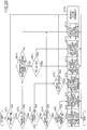
- FIG. 12 is a flowchart illustrating a flow of the pressure storing and pressure discharge operation, and the controller 30 repeatedly executes this pressure storing and pressure discharge operation at predetermined intervals.
- FIG. 13 is a correspondence table illustrating the correspondence between the state of the hydraulic circuit of FIG. 11 and the state of the selector valves.
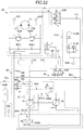
- FIG. 14 illustrates the state of the hydraulic circuit in "pump pressure discharge”
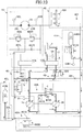
- FIG. 15 illustrates the state of the hydraulic circuit in "motor pressure discharge.”
- the controller 30 determines whether a hydraulic actuator has been operated based on the outputs of various sensors for detecting the condition of the shovel (step ST1). According to this embodiment, the controller 30 determines whether a hydraulic actuator has been operated based on the outputs of the pressure sensor 29.
- the controller 30 determines whether the operation is a regenerative operation or a power running operation (step ST2). According to this embodiment, the controller 30 determines, based on the outputs of the pressure sensor 29, whether a regenerative operation such as a turning speed reduction operation or a boom lowering operation has been performed or a power running operation such as a turning speed increasing operation or a boom raising operation has been performed.
- the controller 30 determines whether the regenerative operation is a turning speed reduction operation or a regenerative operation other than that (step ST3).
- step ST4 it is determined whether the accumulator part 41 is ready to store pressure.
- the controller 30 determines whether the accumulator part 41 is ready to store pressure based on the pressure Pso on the braking side (discharge side) of the turning hydraulic motor 21, output by the pressure sensor S2L or the pressure sensor S2R, and the accumulator pressure Pa output by the pressure sensor S3.
- the controller 30 determines that the accumulator part 41 is ready to store pressure if the pressure Pso exceeds the accumulator pressure Pa, and determines that the accumulator part 41 is not ready to store pressure if the pressure Pso is less than or equal to the accumulator pressure Pa.
- the controller 30 In response to determining that the accumulator part 41 is ready to store pressure (YES at step ST4), the controller 30 sets the state of the hydraulic circuit to the "turning pressure storage" state (step ST5).
- the controller 30 sets the accumulator selector valve 411 to the second position so as to cause the accumulator 410 to communicate with other parts of the hydraulic circuit. Furthermore, the controller 30 sets the first selector valve 420 to the first position or third position so as to cause the turning control part 40 to communicate with the accumulator part 41 via the first pressure storage part 42. Furthermore, the controller 30 sets the second selector valve 430 to the first position so as to cause the discharge port of the boom cylinder flow control valve 17B to communicate with the tank and interrupt the communication between the discharge port of the boom cylinder flow control valve 17B and the accumulator part 41.
- the controller 30 sets the third selector valve 440A to the first position so as to cause the junction on the upstream side of the main pump 14 to communicate with the discharge port of the pump motor 35. Furthermore, the controller 30 sets the fourth selector valve 450A to the first position so as to interrupt the communication between the junction on the upstream side of the main pump 14 and the accumulator part 41. Furthermore, the controller 30 stops the pump motor 35 so as to interrupt the communication between the third selector valve 440A and the accumulator part 41.
- stopping the pump motor 35 includes setting the minimum flow rate (for example, substantially zero), or disengaging a clutch mechanism or switching to such a transmission gear ratio as to cause the output rotational speed of a continuously variable transmission mechanism to be substantially zero. That is, the controller 30 prevents the pump motor 35 from supplying hydraulic oil in the accumulator part 41 to the upstream side and the downstream side of the main pump 14.
- the controller 30 determines whether the accumulator part 41 is ready to store pressure (step ST6). According to this embodiment, the controller 30 determines whether the accumulator part 41 is ready to store pressure based on the pressure Pbb of the bottom-side oil chamber of the boom cylinder 7, output by the pressure sensor S4, and the accumulator pressure Pa output by the pressure sensor S3.
- the controller 30 determines that the accumulator part 41 is ready to store pressure if the pressure Pbb exceeds the accumulator pressure Pa, and determines that the accumulator part 41 is not ready to store pressure if the pressure Pbb is less than or equal to the accumulator pressure Pa.
- the controller 30 sets the state of the hydraulic system to the "hydraulic cylinder pressure storage” state (step ST7). According to this embodiment, the controller 30 sets the state of the hydraulic circuit to the "hydraulic cylinder pressure storage" state in response to determining that the regenerative operation is a boom lowering operation.
- the controller 30 sets the first selector valve 420 to the second position so as to interrupt the communication between the turning control part 40 and the accumulator part 41 via the first pressure storage part 42. Furthermore, the controller 30 sets the second selector valve 430 to the second position so as to cause the discharge port of the boom cylinder flow control valve 17B to communicate with the accumulator part 41 and interrupt the communication between the discharge port of the boom cylinder flow control valve 17B and the tank.
- the bottom-side hydraulic oil of the boom cylinder 7 flows to the accumulator part 41 via the second pressure storage part 43 so as to be stored in the accumulator 410. Furthermore, because each of the first selector valve 420, the third selector valve 440A, and the fourth selector valve 450A is closed relative to the accumulator part 41, the bottom-side hydraulic oil of the boom cylinder 7 is prevented from flowing into locations other than the accumulator part 41.
- the controller 30 determines whether the pressure storage condition of the accumulator part 41 is appropriate for pressure discharge (step ST8). According to this embodiment, the controller 30 determines whether the accumulator pressure Pa is less than a predetermined pressure Pa0 based on the output of the pressure sensor S3.
- the controller 30 determines whether the accumulator pressure Pa is less than the discharge pressure Pp that is the output of the pressure sensor S1 (step ST9). According to this embodiment, in response to determining that the accumulator pressure Pa is more than or equal to the predetermined pressure Pa0, the controller determines whether the accumulator pressure Pa is less than the discharge pressure Pp.
- the controller 30 sets the state of the hydraulic circuit to a state of "pump pressure discharge” (step ST10).
- the controller 30 sets the first selector valve 420 to the second position so as to interrupt the communication between the turning control part 40 and the accumulator part 41 via the first pressure storage part 42. Furthermore, the controller 30 sets the second selector valve 430 to the first position so as to cause the discharge port of the boom cylinder flow control valve 17B to communicate with the tank and interrupt the communication between the discharge port of the boom cylinder flow control valve 17B and the accumulator part 41. Furthermore, the controller 30 sets the third selector valve 440A to the second position so as to cause the junction on the downstream side of the main pump 14 to communicate with the accumulator part 41. Furthermore, the controller 30 sets the fourth selector valve 450A to the second position so as to cause the junction on the upstream side of the main pump 14 to communicate with the accumulator part 41. Furthermore, the controller 30 causes the pump motor 35 to operate as a hydraulic pump.
- part of the hydraulic oil in the accumulator part 41 has its pressure increased to be more than or equal to the discharge pressure Pp by the pump motor 35 and is discharged at the junction on the downstream side of the main pump 14 through the third selector valve 440A. Furthermore, another part of the hydraulic oil in the accumulator part 41 is discharged at the junction on the upstream side of the main pump 14 through the second pressure discharge part 45A, and has its pressure increased to be more than or equal to the discharge pressure Pp by the main pump 14.
- the hydraulic oil discharged by the main pump 14 merges with hydraulic oil from the third selector valve 440A so as to flow toward the control valve 17.
- each of the first selector valve 420 and the second selector valve 430 is closed relative to the accumulator part 41, hydraulic oil in the accumulator part 41 is prevented from being discharged at locations other than the junction on the upstream side and the junction on the downstream side of the main pump 14.
- the controller 30 sets the state of the hydraulic circuit to a state of "motor pressure discharge" (step ST11).
- the controller 30 sets the third selector valve 440A to the first position so as to cause the junction on the upstream side of the main pump 14 to communicate with the discharge port of the pump motor 35. Furthermore, the controller 30 sets the fourth selector valve 450A to the first position so as to interrupt the communication between the junction on the upstream side of the main pump 14 and the accumulator part 41. Furthermore, the controller 30 causes the pump motor 35 to operate as a hydraulic motor.
- a description of the states of the accumulator selector valve 411, the first selector valve 420, and the second selector valve 430, which are the same as the states at the time of "pump pressure discharge,” is omitted.
- hydraulic oil in the accumulator part 41 has its pressure reduced to be less than the discharge pressure Pp by the pump motor 35, and is discharged at the junction on the upstream side of the main pump 14 through the third selector valve 440A. Furthermore, because each of the first selector valve 420, the second selector valve 430, and the fourth selector valve 450A is closed relative to the accumulator part 41, hydraulic oil in the accumulator part 41 is prevented from being discharged at locations other than the junction on the upstream side of the main pump 14.
- the controller 30 sets the state of the hydraulic circuit to the "tank supply” state (step ST12), and prevents hydraulic oil from being discharged from the accumulator part 41.
- the controller 30 sets the accumulator selector valve 411 to the first position so as to interrupt the communication between the accumulator 410 and other parts of the hydraulic circuit. Furthermore, the controller 30 sets the third selector valve 440A to the first position so as to cause the junction on the upstream side of the main pump 14 to communicate with the discharge port of the pump motor 35. Furthermore, the controller 30 sets the fourth selector valve 450A to the first position so as to interrupt the communication between the junction on the upstream side of the main pump 14 and the accumulator part 41. Furthermore, the controller 30 stops the pump motor 35 so as to interrupt the communication between the third selector valve 440A and the accumulator part 41.
- a description of the states of the first selector valve 420 and the second selector valve 430, which are the same as the states at the time of "pump pressure discharge,” is omitted.
- the main pump 14 supplies hydraulic oil drawn in from the tank to a hydraulic actuator in operation. Furthermore, because each of the first selector valve 420, the second selector valve 430, the third selector valve 440A, and the fourth selector valve 450A is closed relative to the accumulator part 41, no hydraulic oil is stored in or discharged from the accumulator part 41.
- the first selector valve 420 and the second selector valve 430 may be switched so as to allow the accumulator part 41 to store hydraulic oil.
- the controller 30 sets the state of the hydraulic circuit to the "standby" state (step ST13).
- the states of the accumulator selector valve 411, the first selector valve 420, the second selector valve 430, the third selector valve 440A, the fourth selector valve 450A, and the pump motor 35 are the same as the states at the time of "tank supply.”
- the "standby" state no hydraulic oil is stored in or discharged from the accumulator part 41.
- the controller 30 sets the state of the hydraulic circuit to the "standby" state (step ST13). In this case, because the first selector valve 420 is at the second position, hydraulic oil on the braking side (discharge side) of the turning hydraulic motor 21 is discharged to the tank via the relief valve 400L or the relief valve 400R.
- the controller 30 sets the state of the hydraulic circuit to the "standby" state (step ST13). In this case, because the second selector valve 430 is at the first position, hydraulic oil in the bottom-side oil chamber of the boom cylinder 7 is discharged to the tank via the boom cylinder flow control valve 17B and the second selector valve 430.
- FIG. 16 illustrates temporal transitions of an operation lever pressure, an accumulator pressure, and control signals for the accumulator selector valve 411, the third selector valve 440A, and the fourth selector valve 450A at the time of the pressure discharge of the accumulator 410.
- the transition of the operation lever pressure Pi at the top of FIG. 16 represents the transition of a pilot pressure that varies in accordance with the operation of a boom operation lever in a boom raising direction.
- the transition of the accumulator pressure Pa in the middle of FIG. 16 represents the transition of the detected value of the pressure sensor S3.
- transitions of control signals at the bottom of FIG. 16 represent the transition of a control signal for the accumulator selector valve 411 (one-dot chain line), a control signal for the third selector valve 440A (solid line), and the transition of a control signal for the fourth selector valve 450A (dotted line).
- the controller 30 determines whether the accumulator pressure Pa is more than or equal to the predetermined pressure Pa0.
- the controller 30 causes hydraulic oil in the accumulator 410 to be discharged.
- the controller 30 causes the discharge of hydraulic oil in the accumulator 410 to be started at time t1.
- the controller 30 in response to determining that the accumulator pressure Pa is more than or equal to the discharge pressure Pp of the main pump 14 at time t1, the controller 30 sets the state of the hydraulic circuit to the "motor pressure discharge" state.
- the discharge pressure Pp which is actually a variable value that varies in accordance with a load, is assumed to be a constant value for simplification of description.
- the controller 30 sets the level of the control signal for the accumulator selector valve 411 to ON level (a level for implementing the second position) at time t1 as illustrated at the bottom of FIG. 16 .
- the accumulator selector valve 411 is set to the second position so as to cause the accumulator 410 to communicate with other parts of the hydraulic circuit.
- the controller 30 causes the pump motor 35 to operate as a hydraulic motor. Therefore, hydraulic oil in the accumulator part 41 has its pressure reduced to be less than the discharge pressure Pp by the pump motor 35, and is discharged at the junction on the upstream side of the main pump 14 through the third selector valve 440A at the first position. In this manner, the bottom-side oil chamber of the boom cylinder 7 receives hydraulic oil discharged from the accumulator 410 so as to expand to raise the boom 4.
- the accumulator 410 discharges hydraulic oil in the accumulator 410 to the junction on the upstream side of the main pump 14. Therefore, the accumulator pressure Pa decreases over time so as to fall below the discharge pressure Pp at time t2 as illustrated in the middle of FIG. 16 .
- the controller 30 In response to determining at time t2 that the accumulator pressure Pa is less than the discharge pressure Pp, the controller 30 sets the state of the hydraulic circuit to the "pump pressure discharge" state.
- the controller 30 sets the level of the control signal for the third selector valve 440A to ON level (a level for implementing the second position) and sets the level of the control signal for the fourth selector valve 450A to ON level as illustrated at the bottom of FIG. 16 .
- the third selector valve 440A is set to the second position so as to cause the junction on the downstream side of the main pump 14 to communicate with the discharge port of the pump motor 35.
- the fourth selector valve 450A is set to the second position so as to cause the junction on the upstream side of the main pump 14 to communicate with the accumulator 410.
- the controller 30 causes the main pump 35 to operate as a hydraulic pump. Therefore, part of the hydraulic oil in the accumulator part 41 has its pressure increased to be more than or equal to the discharge pressure Pp by the pump motor 35 and is discharged at the junction on the downstream side of the main pump 14 through the third selector valve 440A. Furthermore, another part of the hydraulic oil in the accumulator part 41 is discharged at the junction on the upstream side of the main pump 14 through the second pressure discharge part 45A, and has its pressure increased to be more than or equal to the discharge pressure Pp by the main pump 14. The hydraulic oil discharged by the main pump 14 merges with hydraulic oil from the third selector valve 440A so as to flow toward the control valve 17. In this manner, the bottom-side oil chamber of the boom cylinder 7 receives hydraulic oil discharged from the accumulator 410 so as to expand to continue raising the boom 4.
- the accumulator 410 discharges another part of the hydraulic oil in the accumulator 410 to the junction on the downstream side of the main pump 14. Thereafter, the accumulator pressure Pa continues to decrease over time so as to fall below the predetermined pressure Pa0 at time t3 as illustrated in the middle of FIG. 16 .
- the controller 30 In response to determining at time t3 that the accumulator pressure Pa is less than the predetermined pressure Pa0, the controller 30 sets the state of the hydraulic circuit to the "tank supply" state.
- the controller 30 sets the level of the control signal for each of the accumulator selector valve 411 and the fourth selector valve 450A to OFF level as illustrated at the bottom of FIG. 16 .
- each of the accumulator selector valve 411 and the fourth selector valve 450A is set to the first position so as to interrupt the communication between the accumulator 410 and other parts of the hydraulic circuit and interrupt the communication between the junction on the upstream side of the main pump 14 and the accumulator 410.
- the controller 30 stops the pump motor 35 so as to interrupt the communication between the junction on the downstream side of the main pump 14 and the accumulator 410.
- the controller 30 stops discharging any hydraulic oil in the accumulator 410. Then, the bottom-side oil chamber of the boom cylinder 7 receives hydraulic oil discharged by the main pump 14 that has drawn in hydraulic oil from the tank, so as to expand to further continue raising the boom 4.
- the boom cylinder flow control valve 17B interrupts the communication between the main pump 14 and the boom cylinder 7 so as to stop expansion of the bottom-side oil chamber of the boom cylinder 7.
- the above-described hydraulic circuit by the above-described configuration, it is possible to store hydraulic oil with regenerable energy discharged from a hydraulic actuator in the accumulator 410 and reuse the stored hydraulic oil. Furthermore, according to the above-described hydraulic circuit, it is made possible to use hydraulic oil in the accumulator part 41 not only when the accumulator pressure Pa is more than or equal to the discharge pressure Pp but also when the accumulator pressure Pa is less than the discharge pressure Pp. Therefore, according to the above-described circuit, it is possible to more efficiently use hydraulic energy stored in the accumulator part 41.
- hydraulic oil is prevented from flowing into the accumulator part 41 when a power running operation is to be performed.
- hydraulic oil may be caused to flow into the accumulator part.
- the controller 30 executes the alternative of turning pressure storage or hydraulic cylinder pressure storage.
- the controller 30 may execute turning pressure storage and hydraulic cylinder pressure storage simultaneously.
- the controller 30 may set the second selector valve 430 to the second position while setting the first selector valve 420 to the first position or the third position.
- hydraulic oil from the accumulator part 41 is caused to merge at the junction on the upstream side or the junction on the downstream side of the main pump 14.
- the present invention is not limited to this configuration.
- the above-described hydraulic circuit may have a configuration that allows the accumulator part 41 to discharge hydraulic oil directly to a hydraulic actuator instead of the configuration of causing hydraulic oil from the accumulator part 41 to merge at the junction on the downstream side of the main pump 14.
- the above-described hydraulic circuit may be configured to cause hydraulic oil from the accumulator part 41 to merge at the junction on the upstream side of the main pump 14.
- the main pump 14 it is made possible to discharge hydraulic oil from the accumulator part 41 at the junction on the upstream side of the main pump 14. Therefore, compared with the case of drawing in relatively low-pressure hydraulic oil from the tank and discharging the drawn-in hydraulic oil, it is possible for the main pump 14 to reduce absorbed horsepower (a torque necessary to discharge a predetermined amount of hydraulic oil) and promote energy saving. Furthermore, it is possible for the main pump 14 to increase the responsiveness of discharge quantity control.
- the accumulator part 41 includes the single accumulator 410.
- the present invention is not limited to this configuration.
- the accumulator part 41 may include two or more accumulators connected in parallel.
- each accumulator may have any capacity.
- the accumulators may have the same capacity or capacities different from each other.
- the accumulators may have different maximum discharge pressures in order to make it possible to select an accumulator as a supply source or a storage destination of hydraulic oil from among the accumulators that are different in maximum discharge pressure in accordance with a required discharge pressure.
- the "maximum discharge pressure” is a maximum pressure dischargeable by an accumulator, and is a pressure determined by the maximum pressure of the accumulator at the time of a pressure storing (regenerative) operation.
- the accumulators may store or discharge pressure at respective different times. Two or more of the accumulators may store or discharge pressure at respective times that overlap or coincide with each other.
- FIG. 17 illustrates a configuration of a main portion of yet another hydraulic circuit provided in the hydraulic shovel of FIG. 1 .
- the hydraulic circuit of FIG. 17 is different from the hydraulic circuit of FIG. 11 in omitting the fourth selector valve 450A, but otherwise is the same as the hydraulic circuit of FIG. 11 .
- the accumulator 410 stores hydraulic oil from the turning hydraulic motor 21 and the boom cylinder 7.
- the present invention is not limited to this configuration.
- the accumulator 410 may be configured to store only hydraulic oil from the turning hydraulic motor 21.
- the second pressure storage part 43 may be omitted.
- the accumulator 410 may also be configured to store only hydraulic oil from one or more hydraulic actuators other than the turning hydraulic motor 21.
- the first pressure storage part 42 may be omitted, and the turning hydraulic motor 21 may be an electric motor.
- FIG. 18 is a block diagram illustrating yet another configuration of the drive system of the hydraulic shovel of FIG. 1 .
- a mechanical power system, a high-pressure hydraulic line, a pilot line, and an electric drive and control system are indicated by a double line, a thick solid line, a broken line, and a thin solid line, respectively.
- the main pump 14 serving as a variable displacement hydraulic pump and the pilot pump 15 serving as a fixed displacement hydraulic pump are connected to the output shaft of the engine 11 serving as a mechanical drive part.
- the control valve 17 is connected to the main pump 14 via the high-pressure hydraulic line 16 and the first pressure discharge part 44.
- the operation apparatus 26 is connected to the pilot pump 15 via the pilot line 25.
- the control valve 17 is a device that controls a hydraulic system in the hydraulic shovel. Hydraulic actuators such as the traveling hydraulic motor 1A (right), the traveling hydraulic motor 1B (left), the boom cylinder 7, the arm cylinder 8, the bucket cylinder 9, and the turning hydraulic motor 21 are connected to the control valve 17 via high-pressure hydraulic lines.
- the operation apparatus 26 includes the lever 26A, the lever 26B, and the pedal 26C.
- the lever 26A, the lever 26B, and the pedal 26C are connected to the control valve 17 and the pressure sensor 29 via the hydraulic lines 27 and 28, respectively.
- the pressure sensor 29 is a sensor for detecting what an operator's operation is using the operation apparatus 26.
- the pressure sensor 29, for example, detects the direction of operation and the amount of operation of a lever or pedal of the operation apparatus 26 corresponding to each hydraulic actuator in the form of pressure, and outputs a detected value to a controller 30. What an operation of the operation apparatus 26 is may be detected using a sensor other than a pressure sensor.
- the controller 30 is a controller serving as a main control part that controls the driving of the hydraulic shovel.
- the controller 30 is composed of a processing unit that includes a CPU (Central Processing Unit) and an internal memory, and controls the driving of the hydraulic shovel by causing the CPU to execute a drive control program stored in the internal memory.
- a processing unit that includes a CPU (Central Processing Unit) and an internal memory
- the pressure sensor S1 is a sensor that detects the discharge pressure of the main pump 14, and outputs a detected value to the controller 30.
- the pressure sensor S2L is a sensor that detects the pressure of hydraulic oil on the first port side of the turning hydraulic motor 21, and outputs a detected value to the controller 30.
- the pressure sensor S2R is a sensor that detects the pressure of hydraulic oil on the second port side of the turning hydraulic motor 21, and outputs a detected value to the controller 30.
- a pressure sensor S3L is a sensor that detects the pressure of hydraulic oil of a low-pressure accumulator part 41L (hereinafter referred to as "low-pressure accumulator pressure"), and outputs a detected value to the controller 30.
- a pressure sensor S3H is a sensor that detects the pressure of hydraulic oil of a high-pressure accumulator part 41H (hereinafter referred to as "high-pressure accumulator pressure"), and outputs a detected value to the controller 30.
- the pressure sensor S4 is a sensor that detects the pressure of hydraulic oil of the bottom-side oil chamber of the boom cylinder 7, and outputs a detected value to the controller 30.
- the low-pressure accumulator part 41L is a hydraulic circuit element that stores hydraulic oil in a hydraulic circuit and discharges the stored hydraulic oil toward the main pump 14. According to this embodiment, the low-pressure accumulator part 41L serves as a tank that stores hydraulic oil. Therefore, according to this embodiment, a tank is omitted. A tank, however, may be additionally provided.
- the high-pressure accumulator part 41H is a hydraulic circuit element that stores hydraulic oil in the hydraulic circuit and discharges the stored hydraulic oil as required. According to this embodiment, the high-pressure accumulator part 41H has a maximum discharge pressure higher than the maximum discharge pressure of the low-pressure accumulator part 41L.
- the "maximum discharge pressure” is a maximum pressure dischargeable by an accumulator, and is a pressure determined by the maximum pressure of the accumulator at the time of a pressure storing (regenerative) operation.
- the first pressure storage part 42 is a hydraulic circuit element that controls a flow of hydraulic oil between the turning hydraulic motor 21 and the high-pressure accumulator part 41H.
- the second pressure storage part 43 is a hydraulic circuit element that controls a flow of hydraulic oil among the control valve 17, the low-pressure accumulator part 41L, and the high-pressure accumulator part 41H.
- the first pressure discharge part 44 is a hydraulic circuit element that controls a flow of hydraulic oil among the main pump 14, the control valve 17, and the high-pressure accumulator part 41H.
- the second pressure discharge part 45 is a hydraulic circuit element that controls a flow of hydraulic oil among the main pump 14, the low-pressure accumulator part 41L, and the high-pressure accumulator part 41H.
- a third pressure storage part 46 is a hydraulic circuit element that controls a flow of hydraulic oil among the main pump 14, the control valve 17, and the low-pressure accumulator part 41L.
- FIG. 19 illustrates a configuration of a main portion of the hydraulic circuit provided in the hydraulic shovel of FIG. 1 .
- the hydraulic circuit illustrated in FIG. 19 mainly includes the turning control part 40, the low-pressure accumulator part 41L, the high-pressure accumulator part 41H, the first pressure storage part 42, the second pressure storage part 43, the first pressure discharge part 44, the second pressure discharge part 45, and the third pressure storage part 46.
- the turning control part 40 mainly includes the turning hydraulic motor 21, the relief valves 400L and 400R, and the check valves 401L and 401R.
- the relief valve 400L is a valve for preventing the pressure of hydraulic oil on the first port 21L side of the turning hydraulic motor 21 from exceeding a predetermined turning relief pressure. Specifically, when the pressure of hydraulic oil on the first port 21L side reaches a predetermined relief pressure, the relief valve 400L discharges the hydraulic oil on the first port 21L side to the low-pressure accumulator part 41L.
- the relief valve 400R is a valve for preventing the pressure of hydraulic oil on the second port 21R side of the turning hydraulic motor 21 from exceeding a predetermined turning relief pressure. Specifically, when the pressure of hydraulic oil on the second port 21R side reaches a predetermined relief pressure, the relief valve 400R discharges the hydraulic oil on the second port 21R side to the low-pressure accumulator part 41L.
- the check valve 401L is a valve for preventing the pressure of hydraulic oil on the first port 21L side from falling below a low-pressure accumulator pressure. Specifically, when the pressure of hydraulic oil on the first port 21L side decreases to the low-pressure accumulator pressure, the check valve 401L supplies hydraulic oil in the low-pressure accumulator part 41L to the first port 21L side.
- the check valve 401R is a valve for preventing the pressure of hydraulic oil on the second port 21R side from falling below the low-pressure accumulator pressure. Specifically, when the pressure of hydraulic oil on the second port 21R side decreases to the low-pressure accumulator pressure, the check valve 401R supplies hydraulic oil in the low-pressure accumulator part 41L to the second port 21R side.
- the low-pressure accumulator part 41L is a hydraulic circuit element that stores hydraulic oil in the hydraulic circuit and discharges the stored hydraulic oil toward the main pump 14. For example, when a power running operation such as a turning speed increasing operation or a boom raising operation is being performed, the low-pressure accumulator part 41L stores hydraulic oil discharged from a hydraulic actuator, and discharges the stored hydraulic oil to the upstream side (intake side) of the main pump 14.
- the low-pressure accumulator part 41L mainly includes a low-pressure accumulator 410L.
- the low-pressure accumulator 410L is a device that stores hydraulic oil in the hydraulic circuit and discharges the stored hydraulic oil.
- the low-pressure accumulator 410L is a spring accumulator that uses the restoring force of a spring.
- the high-pressure accumulator part 41H is a hydraulic circuit element that stores hydraulic oil in the hydraulic circuit and discharges the stored hydraulic oil as required. Specifically, the high-pressure accumulator part 41H stores hydraulic oil on the braking side (discharge side) of the turning hydraulic motor 21 during turning speed reduction. Furthermore, the high-pressure accumulator part 41H stores hydraulic oil that the boom cylinder 7 discharges during a boom lowering operation. The high-pressure accumulator part 41H discharges the stored hydraulic oil to the upstream side (intake side) or the downstream side (discharge side) of the main pump 14 when a hydraulic actuator is operated.
- the high-pressure accumulator part 41H mainly includes a high-pressure accumulator 410H.
- the high-pressure accumulator 410H is a device that stores hydraulic oil in the hydraulic circuit, and discharges the stored hydraulic oil as required.
- the high-pressure accumulator 410H is a spring accumulator that uses the restoring force of a spring.
- the first pressure storage part 42 is a hydraulic circuit element that controls a flow of hydraulic oil between the turning control part 40 (the turning hydraulic motor 21) and the high-pressure accumulator part 41H.
- the first pressure storage part 42 mainly includes the first selector valve 420 and the first check valve 421.
- the first selector valve 420 is a valve that controls a flow of hydraulic oil from the turning control part 40 to the high-pressure accumulator part 41H at the time of the pressure storing (regenerative) operation of the high-pressure accumulator part 41H.
- the first selector valve 420 is a three-port, three-position selector valve, for which a solenoid valve that switches valve positions in accordance with a control signal from the controller 30 is used.
- a proportional valve using a pilot pressure may be used.
- the first selector valve 420 has a first position, a second position, and a third position as valve positions.
- parenthesized numbers indicate the numbers of valve positions. The same is the case with other selector valves.
- the first position is a valve position that causes the first port 21L to communicate with the high-pressure accumulator part 41H.
- the second position is a valve position that interrupts the communication between the turning control part 40 and the high-pressure accumulator part 41H.
- the third position is a valve position that causes the second port 21R to communicate with the high-pressure accumulator part 41H.
- the first check valve 421 is a valve that prevents hydraulic oil from flowing from the high-pressure accumulator part 41H to the turning control part 40.
- the second pressure storage part 43 is a hydraulic circuit element that controls a flow of hydraulic oil between the control valve 17 and the high-pressure accumulator part 41H.
- the second pressure storage part 43 is disposed among the boom cylinder flow control valve 17B, the low-pressure accumulator part 41L, and the high-pressure accumulator part 41H, and mainly includes the second selector valve 430 and the second check valve 431.
- the boom cylinder flow control valve 17B may be one or more of the other flow control valves such as an arm cylinder flow control valve.
- the second selector valve 430 is a valve that controls a flow of hydraulic oil from a hydraulic actuator to the high-pressure accumulator part 41H at the time of the pressure storing (regenerative) operation of the high-pressure accumulator part 41H.
- the second selector valve 430 is a three-port, two-position selector valve, for which a solenoid valve that switches valve positions in accordance with a control signal from the controller 30 is used.
- a proportional valve using a pilot pressure may be used.
- the second selector valve 430 has a first position and a second position as valve positions.
- the first position is a valve position that causes the discharge port of the boom cylinder flow control valve 17B to communicate with the low-pressure accumulator part 41L and interrupts the communication between the discharge port of the boom cylinder flow control valve 17B and the high-pressure accumulator part 41H.
- the second position is a valve position that causes the discharge port of the boom cylinder flow control valve 17B to communicate with the high-pressure accumulator part 41H and interrupts the communication between the discharge port of the boom cylinder flow control valve 17B and the low-pressure accumulator part 41L.
- the second check valve 431 is a valve that prevents hydraulic oil from flowing from the high-pressure accumulator part 41H to the second selector valve 430.
- the first pressure discharge part 44 is a hydraulic circuit element that controls a flow of hydraulic oil among the main pump 14, the control valve 17, and the high-pressure accumulator part 41H. According to this embodiment, the first pressure discharge part 44 mainly includes the third selector valve 440 and the third check valve 441.
- the third selector valve 440 is a valve that controls a flow of hydraulic oil from the high-pressure accumulator part 41H to a junction on the downstream side of the main pump 14 at the time of the pressure discharge (power running) operation of the high-pressure accumulator part 41H.
- the third selector valve 440 is a two-port, two-position selector valve, for which a solenoid valve that switches valve positions in accordance with a control signal from the controller 30 is used. Alternatively, a proportional valve using a pilot pressure may be used.
- the third selector valve 440 has a first position and a second position as valve positions.
- the first position is a valve position that interrupts the communication between the junction on the downstream side of the main pump 14 and the high-pressure accumulator part 41H. Furthermore, the second position is a valve position that causes the junction on the downstream side of the main pump 14 to communicate with the high-pressure accumulator part 41H.
- the third check valve 441 is a valve that prevents hydraulic oil from flowing from the main pump 14 to the high-pressure accumulator part 41H.
- the second pressure discharge part 45 is a hydraulic circuit element that controls a flow of hydraulic oil among the low-pressure accumulator part 41L, the main pump 14, and the high-pressure accumulator part 41H. According to this embodiment, the second pressure discharge part 45 mainly includes the fourth selector valve 450.
- the fourth selector valve 450 is a valve that controls a flow of hydraulic oil from the high-pressure accumulator part 41H to a junction on the upstream side of the main pump 14 at the time of the pressure discharge (power running) operation of the high-pressure accumulator part 41H.
- the fourth selector valve 450 is a three-port, two-position selector valve, for which a solenoid valve that switches valve positions in accordance with a control signal from the controller 30 is used.
- a proportional valve using a pilot pressure may be used.
- the fourth selector valve 450 has a first position and a second position as valve positions.
- the first position is a valve position that causes the main pump 14 to communicate with the low-pressure accumulator part 41L and interrupts the communication between the main pump 14 and the high-pressure accumulator part 41H.
- the second position is a valve position that interrupts the communication between the main pump 14 and the low-pressure accumulator part 41L and causes the main pump 14 to communicate with the high-pressure accumulator part 41H.
- the third pressure storage part 46 is a hydraulic circuit element that controls a flow of hydraulic oil among the main pump 14, the control valve 17, and the low-pressure accumulator part 41L.
- the third pressure storage part 46 mainly includes a fifth selector valve 460, a fifth check valve 461, a sixth check valve 462, and a seventh check valve 463.
- the fifth selector valve 460 is a valve that controls a flow of hydraulic oil from the main pump 14 to the low-pressure accumulator part 41L at the time of the pressure storing (regenerative) operation of the low-pressure accumulator part 41L.
- the fifth selector valve 460 is a two-port, two-position selector valve, for which a solenoid valve that switches valve positions in accordance with a control signal from the controller 30 is used. Alternatively, a proportional valve using a pilot pressure may be used.
- the fifth selector valve 460 has a first position and a second position as valve positions.
- the first position is a valve position that interrupts the communication between the junction on the downstream side of the main pump 14 and the low-pressure accumulator part 41L.
- the second position is a valve position that causes the junction on the downstream side of the main pump 14 to communicate with the low-pressure accumulator part 41L.
- the fifth check valve 461 is a valve that prevents hydraulic oil from flowing from the low-pressure accumulator part 41L to the junction on the downstream side of the main pump 14.
- the sixth check valve 462 is a valve that prevents hydraulic oil from flowing from the low-pressure accumulator part 41L to the boom cylinder flow control valve 17B.
- the seventh check valve 463 is a valve that prevents hydraulic oil from flowing from the low-pressure accumulator part 41L to a turning hydraulic motor flow control valve 17A.
- FIG. 20 is a flowchart illustrating a flow of the pressure storing and pressure discharge operation, and the controller 30 repeatedly executes this pressure storing and pressure discharge operation at predetermined intervals.
- FIG. 21 is a correspondence table illustrating the correspondence between the state of the hydraulic circuit of FIG. 19 and the state of the selector valves.
- the controller 30 determines whether a hydraulic actuator has been operated based on the outputs of various sensors for detecting the condition of the shovel (step ST1). According to this embodiment, the controller 30 determines whether a hydraulic actuator has been operated based on the outputs of the pressure sensor 29.
- the controller 30 determines whether the operation is a regenerative operation or a power running operation (step ST2). According to this embodiment, the controller 30 determines, based on the outputs of the pressure sensor 29, whether a regenerative operation such as a turning speed reduction operation or a boom lowering operation has been performed or a power running operation such as a turning speed increasing operation or a boom raising operation has been performed. For example, the controller 30 determines that a regenerative operation is being performed when a pressure Pc of hydraulic oil discharged by the hydraulic actuator is more than or equal to a predetermined pressure Pc0.
- the controller 30 determines whether the regenerative operation is a turning speed reduction operation or a regenerative operation other than that (step ST3).
- the controller 30 determines whether the high-pressure accumulator part 41H is ready to store pressure (step ST4). According to this embodiment, the controller 30 determines whether the high-pressure accumulator part 41H is ready to store pressure based on the pressure Pso on the braking side (discharge side) of the turning hydraulic motor 21, output by the pressure sensor S2L or the pressure sensor S2R, and a high-pressure accumulator pressure Pa output by the pressure sensor S3H.
- the controller 30 determines that the high-pressure accumulator part 41H is ready to store pressure if the pressure Pso exceeds the high-pressure accumulator pressure Pa, and determines that the high-pressure accumulator part 41H is not ready to store pressure if the pressure Pso is less than or equal to the high-pressure accumulator pressure Pa.
- the controller 30 determines whether the hydraulic actuator is in a regenerative operation (step ST5). According to this embodiment, the controller 30 determines, based on the outputs of the pressure sensor 29, whether a boom lowering operation is being performed, that is, whether the boom cylinder 7 is in a regenerative operation.
- the controller 30 sets the state of the hydraulic circuit to a "first state” (step ST6).
- the controller 30 sets the state of the hydraulic circuit to the "first state” when a turning speed reduction operation and a boom lowering operation are being performed.
- the controller 30 sets the first selector valve 420 to the first position or the second position so as to cause the turning control part 40 to communicate with the high-pressure accumulator part 41H through the first pressure storage part 42. Furthermore, the controller 30 sets the second selector valve 430 to the second position so as to cause the discharge port of the boom cylinder flow control valve 17B to communicate with the high-pressure accumulator part 41H and interrupt the communication between the discharge port of the boom cylinder flow control valve 17B and the low-pressure accumulator part 41L. Furthermore, the controller 30 sets the third selector valve 440 to the first position so as to interrupt the communication between the junction on the downstream side of the main pump 14 and the high-pressure accumulator part 41H.
- controller 30 sets the fourth selector valve 450 to the first position so as to cause the main pump 14 to communicate with the low-pressure accumulator part 41L and interrupt the communication between the main pump 14 and the high-pressure accumulator part 41H. Furthermore, the controller 30 sets the fifth selector valve 460 to the first position so as to interrupt the communication between the junction on the downstream side of the main pump 14 and the low-pressure accumulator part 41L.
- the high-pressure accumulator part 41H receives hydraulic oil from the turning hydraulic motor 21 and the boom cylinder 7.
- hydraulic oil in the low-pressure accumulator part 41L is discharged at the junction on the upstream side of the main pump 14 through the second pressure discharge part 45.
- “First State Low-Pressure A Pressure Discharge High-Pressure A Pressure Storage (Simultaneous Regeneration)" (where "A” means an accumulator) in FIG. 20 represents such a state of the hydraulic circuit.
- the controller 30 sets the state of the hydraulic circuit to a "second state" (step ST7).
- the controller 30 sets the state of the hydraulic circuit to the "second state” when a turning speed reduction operation is being performed but a boom lowering operation is not being performed.
- the controller 30 sets the second selector valve 430 to the first position so as to cause the discharge port of the boom cylinder flow control valve 17B to communicate with the low-pressure accumulator part 41L and interrupt the communication between the discharge port of the boom cylinder flow control valve 17B and the high-pressure accumulator part 41H.
- the high-pressure accumulator part 41H receives hydraulic oil from the turning hydraulic motor 21.
- hydraulic oil in the low-pressure accumulator part 41L is discharged at the junction on the upstream side of the main pump 14 through the second pressure discharge part 45.
- "Second State Low-Pressure A Pressure Discharge High-Pressure A Pressure Storage (Turning Regeneration)" in FIG. 20 represents such a state of the hydraulic circuit.
- the controller 30 determines whether the high-pressure accumulator part 41H is ready to store pressure (step ST8). According to this embodiment, the controller 30 determines whether the high-pressure accumulator part 41H is ready to store pressure based on the pressure Pbb of the bottom-side oil chamber of the boom cylinder 7, output by the pressure sensor S4, and the high-pressure accumulator pressure Pa output by the pressure sensor S3H.
- the controller 30 determines that the high-pressure accumulator part 41H is ready to store pressure if the pressure Pbb exceeds the high-pressure accumulator pressure Pa, and determines that the high-pressure accumulator part 41H is not ready to store pressure if the pressure Pbb is less than or equal to the high-pressure accumulator pressure Pa.
- the controller 30 sets the state of the hydraulic system to a "third state” (step ST9).
- the controller 30 sets the first selector valve 420 to the second position so as to interrupt the communication between the turning control part 40 and the high-pressure accumulator part 41H.
- the high-pressure accumulator part 41H receives hydraulic oil from the boom cylinder 7.
- hydraulic oil in the low-pressure accumulator part 41L is discharged at the junction on the upstream side of the main pump 14 through the second pressure discharge part 45.
- "Third State Low-Pressure A Pressure Discharge High-Pressure A Pressure Storage (Hydraulic Cylinder Regeneration)" in FIG. 20 represents such a state of the hydraulic circuit.
- the controller 30 determines whether the pressure storage condition of the high-pressure accumulator part 41H is appropriate for pressure discharge (step ST10). According to this embodiment, the controller 30 determines whether the high-pressure accumulator pressure Pa is less than the predetermined pressure Pa0 based on the output of the pressure sensor S3H.
- the controller 30 determines whether the high-pressure accumulator pressure Pa is more than or equal to the discharge pressure Pp that is the output of the pressure sensor S1 (step ST11). According to this embodiment, in response to determining that the high-pressure accumulator pressure Pa is more than or equal to the predetermined pressure Pa0, the controller determines whether the high-pressure accumulator pressure Pa is more than or equal to the discharge pressure Pp.
- the controller 30 In response to determining that the high-pressure accumulator pressure Pa is more than or equal to the discharge pressure Pp (YES at step ST11), the controller 30 sets the state of the hydraulic circuit to a "fourth state" (step ST12).
- the controller 30 sets the first selector valve 420 to the second position so as to interrupt the communication between the turning control part 40 and the high-pressure accumulator part 41H. Furthermore, the controller 30 sets the second selector valve 430 to the first position so as to cause the discharge port of the boom cylinder flow control valve 17B to communicate with the low-pressure accumulator part 41L and interrupt the communication between the discharge port of the boom cylinder flow control valve 17B and the high-pressure accumulator part 41H. Furthermore, the controller 30 sets the third selector valve 440 to the second position so as to cause the junction on the downstream side of the main pump 14 to communicate with the high-pressure accumulator part 41H. A description of the states of the fourth selector valve 450 and the fifth selector valve 460, which are the same as in the "first state,” is omitted.
- the low-pressure accumulator part 41L receives hydraulic oil from the turning hydraulic motor 21 and the boom cylinder 7. On this basis, hydraulic oil in the low-pressure accumulator part 41L is discharged at the junction on the upstream side of the main pump 14 through the second pressure discharge part 45. Furthermore, hydraulic oil in the high-pressure accumulator part 41H is discharged at the junction on the downstream side of the main pump 14 through the first pressure discharge part 44.
- "Fourth State Low-Pressure A Pressure Discharge High-Pressure A Downstream Side Pressure Discharge" in FIG. 20 represents such a state of the hydraulic circuit.
- the controller 30 sets the state of the hydraulic circuit to a "fifth state" (step ST13).
- the controller 30 sets the third selector valve 440 to the first position so as to interrupt the communication between the junction on the downstream side of the main pump 14 and the high-pressure accumulator part 41H. Furthermore, the controller 30 sets the fourth selector valve 450 to the second position so as to cause the main pump 14 to communicate with the high-pressure accumulator part 41H and interrupt the communication between the main pump 14 and the low-pressure accumulator part 41L. Furthermore, the controller 30 sets the fifth selector valve 460 to the first position so as to interrupt the communication between the junction on the downstream side of the main pump 14 and the low-pressure accumulator part 41L.
- the low-pressure accumulator part 41L receives hydraulic oil from the turning hydraulic motor 21 and the boom cylinder 7. Furthermore, hydraulic oil in the high-pressure accumulator part 41H is discharged at the junction on the upstream side of the main pump 14 through the second pressure discharge part 45.
- "Fifth State Low-Pressure A Pressure Storage High-Pressure A Upstream Side Pressure Discharge” in FIG. 20 represents such a state of the hydraulic circuit.
- the controller 30 sets the state of the hydraulic circuit to a "sixth state" (step ST14).
- the controller 30 sets the fourth selector valve 450 to the first position so as to cause the main pump 14 to communicate with the low-pressure accumulator part 41L and interrupt the communication between the main pump 14 and the high-pressure accumulator part 41H.
- the high-pressure accumulator 41H neither receives hydraulic oil from the turning hydraulic motor 21 and the boom cylinder 7 nor discharges hydraulic oil at the junction on the upstream side and the junction on the downstream side of the main pump 14. Furthermore, the low-pressure accumulator part 41L discharges hydraulic oil at the junction on the upstream side of the main pump 14 through the second pressure discharge part 45. Then, the main pump 14 supplies hydraulic oil drawn in from the low-pressure accumulator part 41L to a hydraulic actuator in operation.
- "Sixth State Low-Pressure A Pressure Storage High-Pressure A Interruption" in FIG. 20 represents such a state of the hydraulic circuit.
- step ST15 the controller 30 sets the state of the hydraulic circuit to a "seventh state" (step ST15).
- the controller 30 sets the fifth selector valve 460 to the second position so as to cause the junction on the downstream side of the main pump 14 to communicate with the low-pressure accumulator part 41L.
- the controller 30 sets the state of the hydraulic circuit to the "seventh state" (step ST15). In this case, because the first selector valve 420 is at the second position, hydraulic oil on the braking side (discharge side) of the turning hydraulic motor 21 is discharged to the low-pressure accumulator part 41L via the relief valve 400L or the relief valve 400R.
- the controller 30 sets the state of the hydraulic system to the "seventh state" (step ST15). In this case, because the second selector valve 420 is at the first position, the hydraulic oil of the bottom-side oil chamber of the boom cylinder 7 is discharged to the low-pressure accumulator part 41L via the boom cylinder flow control valve 17B and the second selector valve 430.
- the low-pressure accumulator part 41L operates as a tank, and is able to discharge hydraulic oil to the upstream side of the main pump 14 and store hydraulic oil discharged from a hydraulic actuator. Therefore, according to the shovel of the embodiment of the present invention, it is possible to omit a tank. Furthermore, it is possible to accommodate the low-pressure accumulator part 41L, the high-pressure accumulator part 41H, etc., in a space where a tank has been accommodated.
- the above-described hydraulic circuit it is possible to store hydraulic oil with regenerable energy discharged from a hydraulic actuator in the high-pressure accumulator 410H and reuse the stored hydraulic oil. Furthermore, according to the above-described hydraulic circuit, it is made possible to use hydraulic oil in the high-pressure accumulator part 41H not only when the high-pressure accumulator pressure Pa is more than or equal to the discharge pressure Pp but also when the high-pressure accumulator pressure Pa is less than the discharge pressure Pp. Therefore, according to the above-described circuit, it is possible to more efficiently use hydraulic energy stored in the high-pressure accumulator part 41H.
- the high-pressure accumulator part 41H it is possible to cause the high-pressure accumulator part 41H to perform a pressure discharge (power running) operation even when the pressure of the high-pressure accumulator part 41H is lower than the drive-side pressure of a hydraulic actuator to be operated.
- a hydraulic actuator is driven using hydraulic oil discharged by the main pump 14 or using both hydraulic oil discharged by the main pump 14 and hydraulic oil stored in the high-pressure accumulator part 41H.
- hydraulic oil it is also possible to allow hydraulic oil to flow from the main pump 14 to the high-pressure accumulator part 41H by omitting the third check valve 441, so that hydraulic oil discharged by the main pump 14 may be stored in the high-pressure accumulator part 41H.
- hydraulic oil from the high-pressure accumulator part 41H is caused to merge at the junction on the upstream side or the junction on the downstream side of the main pump 14.
- the present invention is not limited to this configuration.
- a hydraulic circuit according to an embodiment of the present invention may have a configuration that allows the high-pressure accumulator part 41H to discharge hydraulic oil directly to a hydraulic actuator (without intervention of the control valve 17) instead of the configuration of causing hydraulic oil from the high-pressure accumulator part 41H to merge at the junction on the downstream side of the main pump 14.
- the above-described hydraulic circuit may be configured to cause hydraulic oil from the high-pressure accumulator part 41H to merge at the junction on the upstream side of the main pump 14.
- the main pump 14 it is made possible to discharge hydraulic oil from the high-pressure accumulator part 41H at the junction on the upstream side of the main pump 14. Therefore, compared with the case of drawing in relatively low-pressure hydraulic oil from the low-pressure accumulator part 41L and discharging the drawn-in hydraulic oil, it is possible for the main pump 14 to reduce absorbed horsepower (a torque necessary to discharge a predetermined amount of hydraulic oil) and promote energy saving. Furthermore, it is possible for the main pump 14 to increase the responsiveness of discharge quantity control.
- the low-pressure accumulator part 41L is used instead of a tank. That is, it is possible to use hydraulic oil having a low-pressure accumulator pressure that is higher than a tank pressure. Therefore, compared with the case of drawing in hydraulic oil from a tank and discharging the drawn-in hydraulic oil, it is possible for the main pump 14 to reduce absorbed horsepower (a torque necessary to discharge a predetermined amount of hydraulic oil) and promote energy saving. Furthermore, it is possible for the main pump 14 to increase the responsiveness of discharge quantity control.
- the low-pressure accumulator part 41L includes the single low-pressure accumulator 410L and the high-pressure accumulator part 41H includes the single high-pressure accumulator 410H.
- the present invention is not limited to this configuration.
- each of the low-pressure accumulator part 41L and the high-pressure accumulator part 41H may include two or more accumulators connected in parallel.
- each accumulator may have any capacity, and the accumulators may have the same capacity or capacities different from each other.
- the accumulators may have different maximum discharge pressures in order to make it possible to select an accumulator as a supply source or a storage destination of hydraulic oil from among the accumulators that are different in maximum discharge pressure in accordance with a required discharge pressure. Furthermore, the accumulators may store or discharge pressure at respective different times. Two or more of the accumulators may store or discharge pressure at respective times that overlap or coincide with each other.
- FIG. 22 illustrates a configuration of a main portion of still another hydraulic circuit provided in the hydraulic shovel of FIG. 1 .
- FIG. 23 illustrates a flow of hydraulic oil from the high-pressure accumulator part 41H to the boom cylinder 7 in the "fourth state" of the hydraulic circuit of FIG. 22 .
- FIG. 24 illustrates a flow of hydraulic oil from the high-pressure accumulator part 41H to the boom cylinder 7 in the "fifth state" of the hydraulic circuit of FIG. 22 .
- the hydraulic circuit of FIG. 22 is different from the hydraulic circuit of FIG. 19 in including an accumulator selector valve 411H and including the first pressure discharge part 44A and the second pressure discharge part 45A in place of the first pressure discharge part 44 and the second pressure discharge part 45, but otherwise is the same as the hydraulic circuit of FIG. 19 . Therefore, a description of common points is omitted, and a description is given in detail of differences.
- the accumulator selector valve 411H is a valve that controls the communication and interruption between the high-pressure accumulator 410H and other parts of the hydraulic circuit.
- the accumulator selector valve 411H is a two-port, two-position selector valve, for which a solenoid valve that switches valve positions in accordance with a control signal from the controller 30 is used. Alternatively, a proportional valve using a pilot pressure may be used.
- the accumulator selector valve 411H has a first position and a second position as valve positions. The first position is a valve position that interrupts the communication between the high-pressure accumulator 410H and other parts of the hydraulic circuit. The second position is a valve position that causes the high-pressure accumulator 410H to communicate with other parts of the hydraulic circuit.
- the first pressure discharge part 44A is a hydraulic circuit element that controls a flow of hydraulic oil among the main pump 14, the control valve 17, and the high-pressure accumulator part 41H.
- the first pressure discharge part 44A mainly includes the pump motor 35, the third selector valve 440A, and the third check valve 441A.
- the pump motor 35 is a variable displacement hydraulic pump motor whose discharge flow rate varies in accordance with a control signal from the controller 30, and the minimum flow rate of the pump motor 35 can be set to be extremely small, preferably, to substantially zero.
- the rotating shaft of the pump motor 35 is connected to the drive shaft of the engine 11.
- the pump motor 35 is connected to the main pump 14 so that rotation may be transmitted between the pump motor 35 and the main pump 14 via the drive shaft of the engine 11.
- the rotating shaft of the pump motor 35 is connected to the rotating shaft of the main pump 14 via the drive shaft of the engine 11.
- the rotating shaft of the pump motor 35 may be connected to the drive shaft of the engine 11 via a clutch mechanism, a continuously variable transmission mechanism (such as an infinitely variable transmission), or the like.
- the pump motor 35 does not have to be one whose minimum flow rate can be set to substantially zero.
- a makeup circuit for preventing cavitation in the pump motor 35 during its stoppage is provided on the upstream side of the pump motor 35.
- the rotating shaft of the pump motor 35 may be connected directly or connected via a clutch mechanism, a continuously variable transmission mechanism (such as an infinitely variable transmission), or the like to the rotating shaft of the main pump 14 without intervention of the drive shaft of the engine 11.
- the pump motor 35 may operate as either a hydraulic pump or a hydraulic motor as required. According to this embodiment, the pump motor 35 operates as a hydraulic motor when the high-pressure accumulator pressure Pa is more than or equal to the discharge pressure Pp of the main pump 14 and operates as a hydraulic pump when the high-pressure accumulator pressure Pa is less than the discharge pressure Pp.
- the pump motor 35 operating as a hydraulic motor assists the rotation of the engine 11 using hydraulic oil in the high-pressure accumulator part 41H that is at a pressure level higher than or equal to the discharge pressure Pp. Then, the pump motor 35 discharges hydraulic oil at a pressure level lower than the discharge pressure Pp, and causes the hydraulic oil to merge at a junction on the upstream side of the main pump 14. Even in the case of operating as a hydraulic motor, however, the pump motor 35 may discharge hydraulic oil at a pressure level higher than or equal to the discharge pressure Pp, and cause the hydraulic oil to merge at a junction on the downstream side of the main pump 14.
- the pump motor 35 operating as a hydraulic pump draws in hydraulic oil in the high-pressure accumulator part 41H at a pressure level lower than the discharge pressure Pp using the driving force of the engine 11. Then, the pump motor 35 discharges hydraulic oil at a pressure level higher than or equal to the discharge pressure Pp, and causes the hydraulic oil to merge at the junction on the downstream side of the main pump 14. Even in the case of operating as a hydraulic pump, however, the pump motor 35 may discharge hydraulic oil at a pressure level lower than the discharge pressure Pp, and cause the hydraulic oil to merge at the junction on the upstream side of the main pump 14.
- the third selector valve 440A is a valve that controls a flow of hydraulic oil from the pump motor 35 to the junction on the upstream side or the junction on the downstream side of the main pump 14 at the time of the pressure discharge (power running) operation of the high-pressure accumulator part 41H.
- the third selector valve 440A is a three-port, two-position selector valve, for which a solenoid valve that switches valve positions in accordance with a control signal from the controller 30 is used. Alternatively, a proportional valve using a pilot pressure may be used.
- the third selector valve 440A has a first position and a second position as valve positions.
- the first position is a valve position that causes the junction on the upstream side of the main pump 14 to communicate with the discharge port of the pump motor 35 and interrupts the communication between the junction on the downstream side of the main pump 14 and the discharge port of the pump motor 35.
- the second position is a valve position that causes the junction on the downstream side of the main pump 14 to communicate with the discharge port of the pump motor 35 and interrupts the communication between the junction on the upstream side of the main pump 14 and the discharge port of the pump motor 35.
- the third check valve 441A is a valve that prevents hydraulic oil from flowing from the upstream side of the main pump 14 to the discharge port of the pump motor 35.
- the second pressure discharge part 45A is a hydraulic circuit element that controls a flow of hydraulic oil among the main pump 14, the low-pressure accumulator part 41L, and the high-pressure accumulator part 41H.
- the second pressure discharge part 45A mainly includes the fourth selector valve 450A and the fourth check valve 451A.
- the fourth selector valve 450A is a valve that controls a flow of hydraulic oil from the high-pressure accumulator part 41H to the junction on the upstream side of the main pump 14 at the time of the pressure discharge (power running) operation of the high-pressure accumulator part 41H.
- the fourth selector valve 450A is a two-port, two-position selector valve, for which a solenoid valve that switches valve positions in accordance with a control signal from the controller 30 is used. Alternatively, a proportional valve using a pilot pressure may be used.
- the fourth selector valve 450A has a first position and a second position as valve positions.
- the first position is a valve position that interrupts the communication between the junction on the upstream side of the main pump 14 and the high-pressure accumulator part 41H. Furthermore, the second position is a valve position that causes the junction on the upstream side of the main pump 14 to communicate with the high-pressure accumulator part 41H.
- the fourth check valve 451A is a valve that prevents hydraulic oil from flowing from the junction on the upstream side of the main pump 14 and the high-pressure accumulator part 41H to the low-pressure accumulator part 41L.
- the controller 30 sets the third selector valve 440A to the first position so as to cause the junction on the upstream side of the main pump 14 to communicate with the discharge port of the pump motor 35. Furthermore, the controller 30 sets the fourth selector valve 450A to the first position so as to interrupt the communication between the upstream side of the main pump 14 and the high-pressure accumulator part 41H. Furthermore, the controller 30 sets the accumulator selector valve 411H to the second position so as to cause the high-pressure accumulator 410H to communicate with other parts of the hydraulic circuit. Then, the controller 30 causes the pump motor 35 to operate as a hydraulic motor.
- hydraulic oil in the high-pressure accumulator part 41H has its pressure reduced to be less than the discharge pressure Pp by the pump motor 35, and is discharged at the junction on the upstream side of the main pump 14 through the third selector valve 440A. Furthermore, because each of the first selector valve 420, the second selector valve 430, and the fourth selector valve 450A is closed relative to the high-pressure accumulator part 41H, hydraulic oil in the high-pressure accumulator part 41H is prevented from being discharged at locations other than the junction on the upstream side of the main pump 14.
- the controller 30 sets the third selector valve 440A to the second position so as to cause the junction on the downstream side of the main pump 14 to communicate with the discharge port of the pump motor 35. Furthermore, the controller 30 sets the fourth selector valve 450A to the second position so as to cause the junction on the upstream side of the main pump 14 to communicate with the high-pressure accumulator part 41H. Then, the controller 30 causes the pump motor 35 to operate as a hydraulic pump.
- a description of the states of the first selector valve 420, the second selector valve 430, and the fifth selector valve 460 which are the same as in the "fifth state" of the above-described hydraulic circuit, is omitted.
- part of the hydraulic oil in the high-pressure accumulator part 41H has its pressure increased to be more than or equal to the discharge pressure Pp by the pump motor 35 and is discharged at the junction on the downstream side of the main pump 14 through the third selector valve 440A. Furthermore, another part of the hydraulic oil in the high-pressure accumulator part 41H is discharged at the junction on the upstream side of the main pump 14 through the second pressure discharge part 45A, and has its pressure increased to be more than or equal to the discharge pressure Pp by the main pump 14. The hydraulic oil discharged by the main pump 14 merges with hydraulic oil from the third selector valve 440A so as to flow toward the control valve 17.
- each of the first selector valve 420 and the second selector valve 430 is closed relative to the high-pressure accumulator part 41H, hydraulic oil in the high-pressure accumulator part 41H is prevented from being discharged at locations other than the junction on the upstream side and the junction on the downstream side of the main pump 14.
- the controller 30 sets the accumulator selector valve 411H to the second position so as to cause the high-pressure accumulator 410H to communicate with other parts of the hydraulic circuit. Furthermore, the controller 30 sets the third selector valve 440A to the first position so as to cause the junction on the upstream side of the main pump 14 to communicate with the discharge port of the pump motor 35. Furthermore, the controller 30 sets the fourth selector valve 450A to the first position so as to interrupt the communication between the junction on the upstream side of the main pump 14 and the high-pressure accumulator part 41H. Then, the controller 30 stops the pump motor 35 so as to interrupt the communication between the third selector valve 440A and the high-pressure accumulator part 41.
- stopping the pump motor 35 includes setting the minimum flow rate (for example, substantially zero), or disengaging a clutch mechanism or switching to such a transmission gear ratio as to cause the output rotational speed of a continuously variable transmission mechanism to be substantially zero. That is, the controller 30 prevents the pump motor 35 from supplying hydraulic oil in the high-pressure accumulator part 41H to the upstream side and the downstream side of the main pump 14.
- the controller 30 sets the accumulator selector valve 411H to the first position so as to interrupt the communication between the high-pressure accumulator 410H and other parts of the hydraulic circuit. Furthermore, the controller 30 sets the fourth selector valve 450A to the first position so as to interrupt the communication between the junction on the upstream side of the main pump 14 and the high-pressure accumulator part 41H. Then, the controller 35 stops the pump motor 35 so as to interrupt the communication between the third selector valve 440A and the high-pressure accumulator part 41H.
- controller 30 sets the fifth selector valve 460 to the second position so as to cause the junction on the downstream side of the main pump 14 to communicate with the low-pressure accumulator part 41L.
- the low-pressure accumulator part 41L discharges the hydraulic oil at the junction on the upstream side of the main pump 14 through the second pressure discharge part 45A.
- the presence of the accumulator selector valve 411H makes it possible for the controller 30 to cause hydraulic oil flowing out from the turning control part 40 through the first selector valve 420 to merge with the junction on the upstream side or the junction on the downstream side of the main pump 14 without being stored in the high-pressure accumulator 410H.
- the controller 30 while setting the accumulator selector valve 411H to the first position and setting the first selector valve 420 to the first position or the third position, the controller 30 causes the pump motor 35 to operate as a hydraulic pump or a hydraulic motor, or sets the fourth selector valve 450A to the second position. As a result, it is possible for the controller 30 to cause hydraulic oil flowing out from the braking side of the turning hydraulic motor 21 to merge with the junction on the upstream side or the downstream side of the main pump 14.
- controller 30 it is possible for the controller 30 to cause hydraulic oil flowing out from the boom cylinder flow control valve 17B through the second selector valve 430 to merge with the junction on the upstream side or the downstream side of the main pump 14 without being stored in the high-pressure accumulator 410H.
- the controller 30 while setting the accumulator selector valve 411H to the first position and setting the second selector valve 430 to the second position, the controller 30 causes the pump motor 35 to operate as a hydraulic pump or a hydraulic motor, or sets the fourth selector valve 450A to the second position. As a result, it is possible for the controller 30 to cause hydraulic oil flowing out from the bottom-side oil chamber of the boom cylinder 7 to merge with the junction on the upstream side or the downstream side of the main pump 14 without being stored in the high-pressure accumulator 410H.
- the hydraulic circuit of FIG. 22 produces the effect that hydraulic oil with regenerable energy discharged from a hydraulic actuator may be reused without being stored in the high-pressure accumulator 410H, in addition to the effect by the hydraulic circuit of FIG. 19 . Furthermore, according to the hydraulic circuit of FIG. 22 , it is possible to reuse the hydraulic oil regardless of whether its pressure is greater than the discharge pressure of the main pump 14 or not.
- the high-pressure accumulator 410H stores hydraulic oil from the turning hydraulic motor 21 and the boom cylinder 7.
- the present invention is not limited to this configuration.
- the high-pressure accumulator 410H may be configured to store only hydraulic oil from the turning hydraulic motor 21.
- the second pressure storage part 43 may be omitted.
- the high-pressure accumulator 410H may also be configured to store only hydraulic oil from one or more hydraulic actuators other than the turning hydraulic motor 21.
- the first pressure storage part 42 may be omitted, and the turning hydraulic motor 21 may be an electric motor.
Landscapes
- Engineering & Computer Science (AREA)
- General Engineering & Computer Science (AREA)
- Physics & Mathematics (AREA)
- Fluid Mechanics (AREA)
- Mechanical Engineering (AREA)
- Mining & Mineral Resources (AREA)
- Civil Engineering (AREA)
- Structural Engineering (AREA)
- Chemical & Material Sciences (AREA)
- Analytical Chemistry (AREA)
- Operation Control Of Excavators (AREA)
- Fluid-Pressure Circuits (AREA)
Abstract
Description
- The present invention relates to a shovel including an accumulator.
- A hydraulic swing motor control system using an accumulator has been known. (See, for example,
Patent Document 1.) - [Patent Document 1]
PCT Japanese Translation Patent Publication No. 2011-514954 - According to this hydraulic swing motor control system, when decelerating a hydraulic swing motor, hydraulic fluid exiting from the hydraulic swing motor is stored in the accumulator in order to convert kinetic energy due to the inertia action of the hydraulic swing motor into hydraulic energy. Furthermore, according to this hydraulic swing motor control system, when accelerating the hydraulic swing motor, the hydraulic fluid stored in the accumulator is discharged to the hydraulic swing motor in order to use the hydraulic energy due to the conversion as kinetic energy.
- According to this hydraulic swing motor control system, however, the hydraulic fluid stored in the accumulator is used only for driving the hydraulic swing motor. Therefore, when the pressure of the accumulator is low, the hydraulic fluid stored in the accumulator is prevented from being discharged to the hydraulic swing motor. Accordingly, the accumulator is not efficiently used.
- In view of the above, it is desired to provide a shovel that makes more efficient use of an accumulator.
- A shovel according to an embodiment of the present invention includes a main pump, a hydraulic actuator configured to be driven with hydraulic oil discharged by the main pump, and an accumulator part configured to store the hydraulic oil discharged from the hydraulic actuator and capable of discharging the hydraulic oil to an intake side of the main pump.
- It is possible for the above-described means to provide a shovel that makes more efficient use of an accumulator.
-
-
FIG. 1 is a side view of a hydraulic shovel according to an embodiment of the present invention. -
FIG. 2 is a block diagram illustrating a configuration of a drive system of the hydraulic shovel ofFIG. 1 . -
FIG. 3 is a diagram illustrating a configuration of a main portion of a hydraulic circuit. -
FIG. 4 is a flowchart illustrating a flow of a pressure storing and pressure discharge operation. -
FIG. 5 is a correspondence table illustrating a correspondence between the state of the hydraulic circuit ofFIG. 3 and the state of selector valves. -
FIG. 6 is a graph illustrating temporal transitions of an operation lever pressure, an accumulator pressure, and control signals at the time of the pressure discharge of an accumulator. -
FIG. 7 is a diagram illustrating a configuration of a main portion of a hydraulic circuit. -
FIG. 8 is a flowchart illustrating a flow of the pressure storing and pressure discharge operation. -
FIG. 9 is a correspondence table illustrating a correspondence between the state of the hydraulic circuit ofFIG. 7 and the state of selector valves. -
FIG. 10 is a block diagram illustrating another configuration of the drive system of the hydraulic shovel ofFIG. 1 . -
FIG. 11 is a diagram illustrating a configuration of a main portion of a hydraulic circuit. -
FIG. 12 is a flowchart illustrating a flow of the pressure storing and pressure discharge operation. -
FIG. 13 is a correspondence table illustrating a correspondence between the state of the hydraulic circuit ofFIG. 11 and the state of selector valves. -
FIG. 14 is a diagram illustrating a flow of hydraulic oil from an accumulator part to a hydraulic cylinder in a pump pressure discharge state. -
FIG. 15 is a diagram illustrating a flow of hydraulic oil from the accumulator part to the hydraulic cylinder in a motor pressure discharge state. -
FIG. 16 is a graph illustrating temporal transitions of an operation lever pressure, an accumulator pressure, and control signals at the time of the pressure discharge of an accumulator. -
FIG. 17 is a diagram illustrating a configuration of a main portion of a hydraulic circuit. -
FIG. 18 is a block diagram illustrating yet another configuration of the drive system of the hydraulic shovel ofFIG. 1 . -
FIG. 19 is a diagram illustrating a configuration of a main portion of a hydraulic circuit. -
FIG. 20 is a flowchart illustrating a flow of the pressure storing and pressure discharge operation. -
FIG. 21 is a correspondence table illustrating a correspondence between the state of the hydraulic circuit ofFIG. 19 and the state of selector valves. -
FIG. 22 is a diagram illustrating a configuration of a main portion of a hydraulic circuit. -
FIG. 23 is a diagram illustrating a "fourth state" of the hydraulic circuit ofFIG. 22 . -
FIG. 24 is a diagram illustrating a "fifth state" of the hydraulic circuit ofFIG. 22 . - A description is given, with reference to the drawings, of embodiments of the present invention.
-
FIG. 1 is a side view of a hydraulic shovel according to an embodiment of the present invention. An upper-part turningbody 3 is mounted on a lower-part travelingbody 1 of the hydraulic shovel via aturning mechanism 2. Aboom 4 is attached to the upper-part turningbody 3. Anarm 5 is attached to an end of theboom 4, and abucket 6 is attached to an end of thearm 5. Theboom 4, thearm 5, and thebucket 6 form an attachment, and are hydraulically driven by aboom cylinder 7, anarm cylinder 8, and abucket cylinder 9, respectively, which are hydraulic cylinders. Acabin 10 is provided and power sources such as an engine are mounted on the upper-part turningbody 3. -
FIG. 2 is a block diagram illustrating a configuration of a drive system of the hydraulic shovel ofFIG. 1 . InFIG. 2 , a mechanical power system, a high-pressure hydraulic line, a pilot line, and an electric drive and control system are indicated by a double line, a thick solid line, a broken line, and a thin solid line, respectively. - A
main pump 14 serving as a variable displacement hydraulic pump and apilot pump 15 serving as a fixed displacement hydraulic pump are connected to the output shaft of anengine 11 serving as a mechanical drive part. Acontrol valve 17 is connected to themain pump 14 via a high-pressurehydraulic line 16 and a firstpressure discharge part 44. Furthermore, anoperation apparatus 26 is connected to thepilot pump 15 via apilot line 25. - The
control valve 17 is a device that controls a hydraulic system in the hydraulic shovel. Hydraulic actuators such as a travelinghydraulic motor 1A (right), a travelinghydraulic motor 1B (left), theboom cylinder 7, thearm cylinder 8, thebucket cylinder 9, and a turninghydraulic motor 21 are connected to thecontrol valve 17 via high-pressure hydraulic lines. - The
operation apparatus 26 includes alever 26A, a lever 26B, and apedal 26C. Thelever 26A, the lever 26B, and thepedal 26C are connected to thecontrol valve 17 and apressure sensor 29 viahydraulic lines - The
pressure sensor 29 is a sensor for detecting what an operator's operation is using theoperation apparatus 26. Thepressure sensor 29, for example, detects the direction of operation and the amount of operation of a lever or pedal of theoperation apparatus 26 corresponding to each hydraulic actuator in the form of pressure, and outputs a detected value to acontroller 30. What an operation of theoperation apparatus 26 is may be detected using a sensor other than a pressure sensor. - The
controller 30 is a controller serving as a main control part that controls the driving of the hydraulic shovel. Thecontroller 30 is composed of a processing unit that includes a CPU (Central Processing Unit) and an internal memory, and controls the driving of the hydraulic shovel by causing the CPU to execute a drive control program stored in the internal memory. - A pressure sensor S1 is a sensor that detects the discharge pressure of the
main pump 14, and outputs a detected value to thecontroller 30. - A pressure sensor S2L is a sensor that detects the pressure of hydraulic oil on the first port side of the turning
hydraulic motor 21, and outputs a detected value to thecontroller 30. - A pressure sensor S2R is a sensor that detects the pressure of hydraulic oil on the second port side of the turning
hydraulic motor 21, and outputs a detected value to thecontroller 30. - A pressure sensor S3 is a sensor that detects the pressure of hydraulic oil of an accumulator part 41 (hereinafter referred to as "accumulator pressure"), and outputs a detected value to the
controller 30. - A pressure sensor S4 is a sensor that detects the pressure of hydraulic oil of the bottom-side oil chamber of the
boom cylinder 7, and outputs a detected value to thecontroller 30. - The
accumulator part 41 is a hydraulic circuit element that stores hydraulic oil in a hydraulic circuit and discharges the stored hydraulic oil as required. - A first
pressure storage part 42 is a hydraulic circuit element that controls a flow of hydraulic oil between the turninghydraulic motor 21 and theaccumulator part 41. - A second
pressure storage part 43 is a hydraulic circuit element that controls a flow of hydraulic oil between thecontrol valve 17 and theaccumulator part 41. - The first
pressure discharge part 44 is a hydraulic circuit element that controls a flow of hydraulic oil among themain pump 14, thecontrol valve 17, and theaccumulator part 41. - A second
pressure discharge part 45 is a hydraulic circuit element that controls a flow of hydraulic oil among themain pump 14, a tank, and theaccumulator part 41. - A description is given in detail below of the
accumulator part 41, the firstpressure storage part 42, the secondpressure storage part 43, the firstpressure discharge part 44, and the secondpressure discharge part 45. - Next, a description is given, with reference to
FIG. 3 , of the pressure storing and the pressure discharge of theaccumulator part 41 provided in the hydraulic shovel ofFIG. 1 .FIG. 3 illustrates a configuration of a main portion of a hydraulic circuit provided in the hydraulic shovel ofFIG. 1 . - The hydraulic circuit illustrated in
FIG. 3 mainly includes a turningcontrol part 40, theaccumulator part 41, the firstpressure storage part 42, the secondpressure storage part 43, the firstpressure discharge part 44, and the secondpressure discharge part 45. - The turning
control part 40 mainly includes the turninghydraulic motor 21,relief valves check valves - The
relief valve 400L is a valve for preventing the pressure of hydraulic oil on thefirst port 21L side of the turninghydraulic motor 21 from exceeding a predetermined turning relief pressure. Specifically, when the pressure of hydraulic oil on thefirst port 21L side reaches a predetermined relief pressure, therelief valve 400L discharges the hydraulic oil on thefirst port 21L side to the tank. - Likewise, the
relief valve 400R is a valve for preventing the pressure of hydraulic oil on thesecond port 21R side of the turninghydraulic motor 21 from exceeding a predetermined turning relief pressure. Specifically, when the pressure of hydraulic oil on thesecond port 21R side reaches a predetermined relief pressure, therelief valve 400R discharges the hydraulic oil on thesecond port 21R side to the tank. - The
check valve 401L is a valve for preventing the pressure of hydraulic oil on thefirst port 21L side from falling below a tank pressure. Specifically, when the pressure of hydraulic oil on thefirst port 21L side decreases to a tank pressure, thecheck valve 401L supplies hydraulic oil in the tank to thefirst port 21L side. - Likewise, the
check valve 401R is a valve for preventing the pressure of hydraulic oil on thesecond port 21R side from falling below a tank pressure. Specifically, when the pressure of hydraulic oil on thesecond port 21R side decreases to a tank pressure, thecheck valve 401R supplies hydraulic oil in the tank to thesecond port 21R side. - The
accumulator part 41 is a hydraulic circuit element that stores hydraulic oil in the hydraulic circuit and discharges the stored hydraulic oil as required. Specifically, theaccumulator part 41 stores hydraulic oil on the braking side (discharge side) of the turninghydraulic motor 21 during turning speed reduction. Furthermore, theaccumulator part 41 stores hydraulic oil that theboom cylinder 7 discharges during a boom lowering operation. Theaccumulator part 41 discharges the stored hydraulic oil to the upstream side (intake side) or the downstream side (discharge side) of themain pump 14 when a hydraulic actuator is operated. - According to this embodiment, the
accumulator part 41 mainly includes anaccumulator 410. Theaccumulator 410 is a device that stores hydraulic oil in the hydraulic circuit, and discharges the stored hydraulic oil as required. According to this embodiment, theaccumulator 410 is a spring accumulator that uses the restoring force of a spring. - The first
pressure storage part 42 is a hydraulic circuit element that controls a flow of hydraulic oil between the turning control part 40 (the turning hydraulic motor 21) and theaccumulator part 41. According to this embodiment, the firstpressure storage part 42 mainly includes afirst selector valve 420 and afirst check valve 421. - The
first selector valve 420 is a valve that controls a flow of hydraulic oil from the turningcontrol part 40 to theaccumulator part 41 at the time of the pressure storing (regenerative) operation of theaccumulator part 41. According to this embodiment, thefirst selector valve 420 is a three-port, three-position selector valve, for which a solenoid valve that switches valve positions in accordance with a control signal from thecontroller 30 is used. Alternatively, a proportional valve using a pilot pressure may be used. Specifically, thefirst selector valve 420 has a first position, a second position, and a third position as valve positions. In the drawing, parenthesized numbers indicate the numbers of valve positions. The same is the case with other selector valves. - The first position is a valve position that causes the
first port 21L to communicate with theaccumulator part 41. The second position is a valve position that interrupts the communication between the turningcontrol part 40 and theaccumulator part 41. The third position is a valve position that causes thesecond port 21R to communicate with theaccumulator part 41. - The
first check valve 421 is a valve that prevents hydraulic oil from flowing from theaccumulator part 41 to the turningcontrol part 40. - The second
pressure storage part 43 is a hydraulic circuit element that controls a flow of hydraulic oil between thecontrol valve 17 and theaccumulator part 41. According to this embodiment, the secondpressure storage part 43 is disposed among a boom cylinderflow control valve 17B, the tank, and theaccumulator part 41, and mainly includes asecond selector valve 430 and asecond check valve 431. The boom cylinderflow control valve 17B may be one or more of the other flow control valves such as an arm cylinder flow control valve. - The
second selector valve 430 is a valve that controls a flow of hydraulic oil from a hydraulic actuator to theaccumulator part 41 at the time of the pressure storing (regenerative) operation of theaccumulator part 41. According to this embodiment, thesecond selector valve 430 is a three-port, two-position selector valve, for which a solenoid valve that switches valve positions in accordance with a control signal from thecontroller 30 is used. Alternatively, a proportional valve using a pilot pressure may be used. Specifically, thesecond selector valve 430 has a first position and a second position as valve positions. The first position is a valve position that causes the discharge port of the boom cylinderflow control valve 17B to communicate with the tank and interrupts the communication between the discharge port of the boom cylinderflow control valve 17B and theaccumulator part 41. Furthermore, the second position is a valve position that causes the discharge port of the boom cylinderflow control valve 17B to communicate with theaccumulator part 41 and interrupts the communication between the discharge port of the boom cylinderflow control valve 17B and the tank. - The
second check valve 431 is a valve that prevents hydraulic oil from flowing from theaccumulator part 41 to thesecond selector valve 430. - The first
pressure discharge part 44 is a hydraulic circuit element that controls a flow of hydraulic oil among themain pump 14, thecontrol valve 17, and theaccumulator part 41. According to this embodiment, the firstpressure discharge part 44 mainly includes athird selector valve 440 and athird check valve 441. - The
third selector valve 440 is a valve that controls a flow of hydraulic oil from theaccumulator part 41 to a junction on the downstream side of themain pump 14 at the time of the pressure discharge (power running) operation of theaccumulator part 41. According to this embodiment, thethird selector valve 440 is a two-port, two-position selector valve, for which a solenoid valve that switches valve positions in accordance with a control signal from thecontroller 30 is used. Alternatively, a proportional valve using a pilot pressure may be used. Specifically, thethird selector valve 440 has a first position and a second position as valve positions. The first position is a valve position that interrupts the communication between the junction on the downstream side of themain pump 14 and theaccumulator part 41. Furthermore, the second position is a valve position that causes the junction on the downstream side of themain pump 14 to communicate with theaccumulator part 41. - The
third check valve 441 is a valve that prevents hydraulic oil from flowing from themain pump 14 to theaccumulator part 41. - The second
pressure discharge part 45 is a hydraulic circuit element that controls a flow of hydraulic oil among the tank, themain pump 14, and theaccumulator part 41. According to this embodiment, the secondpressure discharge part 45 mainly includes afourth selector valve 450. - The
fourth selector valve 450 is a valve that controls a flow of hydraulic oil from theaccumulator part 41 to a junction on the upstream side of themain pump 14 at the time of the pressure discharge (power running) operation of theaccumulator part 41. According to this embodiment, thefourth selector valve 450 is a three-port, two-position selector valve, for which a solenoid valve that switches valve positions in accordance with a control signal from thecontroller 30 is used. Alternatively, a proportional valve using a pilot pressure may be used. Specifically, thefourth selector valve 450 has a first position and a second position as valve positions. The first position is a valve position that causes themain pump 14 to communicate with the tank and interrupts the communication between themain pump 14 and theaccumulator part 41. Furthermore, the second position is a valve position that interrupts the communication between themain pump 14 and the tank and causes themain pump 14 to communicate with theaccumulator part 41. - Here, a description is given, with reference to
FIGS. 4 and5 , of thecontroller 30's operation of controlling the pressure storing and the pressure discharge of the accumulator part 41 (hereinafter, "pressure storing and pressure discharge operation").FIG. 4 is a flowchart illustrating a flow of the pressure storing and pressure discharge operation, and thecontroller 30 repeatedly executes this pressure storing and pressure discharge operation at predetermined intervals.FIG. 5 is a correspondence table illustrating the correspondence between the state of the hydraulic circuit ofFIG. 3 and the state of the selector valves. - First, the
controller 30 determines whether a hydraulic actuator has been operated based on the outputs of various sensors for detecting the condition of the shovel (step ST1). According to this embodiment, thecontroller 30 determines whether a hydraulic actuator has been operated based on the outputs of thepressure sensor 29. - In response to determining that a hydraulic actuator has been operated (YES at step ST1), the
controller 30 determines whether the operation is a regenerative operation or a power running operation (step ST2). According to this embodiment, thecontroller 30 determines, based on the outputs of thepressure sensor 29, whether a regenerative operation such as a turning speed reduction operation or a boom lowering operation has been performed or a power running operation such as a turning speed increasing operation or a boom raising operation has been performed. - In response to determining that a regenerative operation has been performed (YES at step ST2), the
controller 30 determines whether the regenerative operation is a turning speed reduction operation or a regenerative operation other than that (step ST3). - In response to determining that the regenerative operation is a turning speed reduction operation (YES at step ST3), the
controller 30 determines whether theaccumulator part 41 is ready to store pressure (step ST4). According to this embodiment, thecontroller 30 determines whether theaccumulator part 41 is ready to store pressure based on a pressure Pso on the braking side (discharge side) of the turninghydraulic motor 21, output by the pressure sensor S2L or the pressure sensor S2R, and an accumulator pressure Pa output by the pressure sensor S3. Specifically, thecontroller 30 determines that theaccumulator part 41 is ready to store pressure if the pressure Pso exceeds the accumulator pressure Pa, and determines that theaccumulator part 41 is not ready to store pressure if the pressure Pso is less than or equal to the accumulator pressure Pa. - In response to determining that the
accumulator part 41 is ready to store pressure (YES at step ST4), thecontroller 30 sets the state of the hydraulic circuit to a state of "turning pressure storage" (step ST5). - As illustrated in
FIG. 5 , in the "turning pressure storage" state, thecontroller 30 sets thefirst selector valve 420 to the first position or third position so as to cause theturning control part 40 to communicate with theaccumulator part 41 via the firstpressure storage part 42. Furthermore, thecontroller 30 sets thesecond selector valve 430 to the first position so as to cause the discharge port of the boom cylinderflow control valve 17B to communicate with the tank and interrupt the communication between the discharge port of the boom cylinderflow control valve 17B and theaccumulator part 41. Furthermore, thecontroller 30 sets thethird selector valve 440 to the first position so as to interrupt the communication between the junction on the downstream side of themain pump 14 and theaccumulator part 41. Furthermore, thecontroller 30 sets thefourth selector valve 450 to the first position so as to cause themain pump 14 to communicate with the tank and interrupt the communication between themain pump 14 and theaccumulator part 41. - As a result, in the "turning pressure storage" state, hydraulic oil on the braking side of the turning
hydraulic motor 21 flows to theaccumulator part 41 via the firstpressure storage part 42 so as to be stored in theaccumulator 410. Furthermore, because each of thesecond selector valve 430, thethird selector valve 440, and thefourth selector valve 450 is closed relative to theaccumulator part 41, hydraulic oil on the braking side of the turninghydraulic motor 21 is prevented from flowing into locations other than theaccumulator part 41. - Furthermore, in response to determining at step ST3 that the regenerative operation is a regenerative operation other than the turning speed reduction operation (NO at step ST3), the
controller 30 determines whether theaccumulator part 41 is ready to store pressure (step ST6). According to this embodiment, thecontroller 30 determines whether theaccumulator part 41 is ready to store pressure based on a pressure Pbb of the bottom-side oil chamber of theboom cylinder 7, output by the pressure sensor S4, and the accumulator pressure Pa output by the pressure sensor S3. Specifically, thecontroller 30 determines that theaccumulator part 41 is ready to store pressure if the pressure Pbb exceeds the accumulator pressure Pa, and determines that theaccumulator part 41 is not ready to store pressure if the pressure Pbb is less than or equal to the accumulator pressure Pa. - In response to determining that the
accumulator part 41 is ready to store pressure (YES at step ST6), thecontroller 30 sets the state of the hydraulic system to a state of "hydraulic cylinder pressure storage" (step ST7). According to this embodiment, thecontroller 30 sets the state of the hydraulic circuit to the "hydraulic cylinder pressure storage" state in response to determining that the regenerative operation is a boom lowering operation. - As illustrated in
FIG. 5 , in the "hydraulic cylinder pressure storage" state, thecontroller 30 sets thefirst selector valve 420 to the second position so as to interrupt the communication between the turningcontrol part 40 and theaccumulator part 41 via the firstpressure storage part 42. Furthermore, thecontroller 30 sets thesecond selector valve 430 to the second position so as to cause the discharge port of the boom cylinderflow control valve 17B to communicate with theaccumulator part 41 and interrupt the communication between the discharge port of the boom cylinderflow control valve 17B and the tank. A description of the states of thethird selector valve 440 and thefourth selector valve 450, which are the same as the states at the time of "turning pressure storage," is omitted. - As a result, in the "hydraulic cylinder pressure storage" state, the bottom-side hydraulic oil of the
boom cylinder 7 flows to theaccumulator part 41 via the secondpressure storage part 43 so as to be stored in theaccumulator 410. Furthermore, because each of thefirst selector valve 420, thethird selector valve 440, and thefourth selector valve 450 is closed relative to theaccumulator part 41, the bottom-side hydraulic oil of theboom cylinder 7 is prevented from flowing into locations other than theaccumulator part 41. - Furthermore, in response to determining at step ST2 that the operation is not a regenerative operation but a power running operation (NO at step ST2), the
controller 30 determines whether the pressure storage condition of theaccumulator part 41 is appropriate for pressure discharge (step ST8). According to this embodiment, thecontroller 30 determines whether the accumulator pressure Pa is less than a predetermined pressure Pa0 based on the output of the pressure sensor S3. - In response to determining that the pressure storage condition of the
accumulator part 41 is appropriate for pressure discharge (YES at step ST8), thecontroller 30 determines whether the accumulator pressure Pa is less than a discharge pressure Pp that is the output of the pressure sensor S1 (step ST9). According to this embodiment, in response to determining that the accumulator pressure Pa is more than or equal to the predetermined pressure Pa0, the controller determines whether the accumulator pressure Pa is less than the discharge pressure Pp. - In response to determining that the accumulator pressure Pa is less than the discharge pressure Pp (YES at step ST9), the
controller 30 sets the state of the hydraulic circuit to a state of "upstream side pressure discharge" (step ST10). - As illustrated in
FIG. 5 , in the "upstream side pressure discharge" state, thecontroller 30 sets thefirst selector valve 420 to the second position so as to interrupt the communication between the turningcontrol part 40 and theaccumulator part 41 via the firstpressure storage part 42. Furthermore, thecontroller 30 sets thesecond selector valve 430 to the first position so as to cause the discharge port of the boom cylinderflow control valve 17B to communicate with the tank and interrupt the communication between the discharge port of the boom cylinderflow control valve 17B and theaccumulator part 41. Furthermore, thecontroller 30 sets thethird selector valve 440 to the first position so as to interrupt the communication between the junction on the downstream side of themain pump 14 and theaccumulator part 41. Furthermore, thecontroller 30 sets thefourth selector valve 450 to the second position so as to interrupt the communication between themain pump 14 and the tank and cause themain pump 14 to communicate with theaccumulator part 41. - As a result, in the "upstream side pressure discharge" state, hydraulic oil in the
accumulator part 41 is discharged at the junction on the upstream side of themain pump 14 through the secondpressure discharge part 45. Furthermore, because each of thefirst selector valve 420, thesecond selector valve 430, and thethird selector valve 440 is closed relative to theaccumulator part 41, hydraulic oil in theaccumulator part 41 is prevented from being discharged at locations other than the junction on the upstream side of themain pump 14. - Furthermore, in response to determining at step ST9 that the accumulator pressure Pa is more than or equal to the discharge pressure Pp (NO at step ST9), the
controller 30 sets the state of the hydraulic circuit to a state of "downstream side pressure discharge" (step ST11). - As illustrated in
FIG. 5 , in the "downstream side pressure discharge" state, thecontroller 30 sets thethird selector valve 440 to the second position so as to cause the junction on the downstream side of themain pump 14 to communicate with theaccumulator part 41. Furthermore, thecontroller 30 sets thefourth selector valve 450 to the first position so as to cause themain pump 14 to communicate with the tank and interrupt the communication between themain pump 14 and theaccumulator part 41. A description of the states of thefirst selector valve 420 and thesecond selector valve 430, which are the same as the states at the time of "upstream side pressure discharge," is omitted. - As a result, in the "downstream side pressure discharge" state, hydraulic oil in the
accumulator part 41 is discharged at the junction on the downstream side of themain pump 14 through the firstpressure discharge part 44. Furthermore, because each of thefirst selector valve 420, thesecond selector valve 430, and thefourth selector valve 450 is closed relative to theaccumulator part 41, hydraulic oil in theaccumulator part 41 is prevented from being discharged at locations other than the junction on the downstream side of themain pump 14. - Furthermore, in response to determining at step ST8 that the pressure storage condition of the
accumulator part 41 is not appropriate for pressure discharge (NO at step ST8), thecontroller 30 sets the state of the hydraulic circuit to a state of "tank supply" (step ST12), and prevents hydraulic oil from being discharged from theaccumulator part 41. - As illustrated in
FIG. 5 , in the "tank supply" state, thecontroller 30 sets thethird selector valve 440 to the first position so as to interrupt the communication between the junction on the downstream side of themain pump 14 and theaccumulator part 41. Furthermore, thecontroller 30 sets thefourth selector valve 450 to the first position so as to cause themain pump 14 to communicate with the tank and interrupt the communication between themain pump 14 and theaccumulator part 41. A description of the states of thefirst selector valve 420 and thesecond selector valve 430, which are the same as the states at the time of "upstream side pressure discharge," is omitted. - As a result, in the "tank supply" state, the
main pump 14 supplies hydraulic oil drawn in from the tank to a hydraulic actuator in operation. Furthermore, because each of thefirst selector valve 420, thesecond selector valve 430, thethird selector valve 440, and thefourth selector valve 450 is closed relative to theaccumulator part 41, no hydraulic oil is stored in or discharged from theaccumulator part 41. Thefirst selector valve 420 and thesecond selector valve 430, however, may be switched so as to allow theaccumulator part 41 to store hydraulic oil. - Furthermore, in response to determining at step ST1 that no hydraulic actuator is operated (NO at step ST1), the
controller 30 sets the state of the hydraulic circuit to a state of "standby" (step ST13). - As illustrated in
FIG. 5 , in the "standby" state, the states of thefirst selector valve 420, thesecond selector valve 430, thethird selector valve 440, and thefourth selector valve 450 are the same as the states at the time of "tank supply." As a result, in the "standby" state, no hydraulic oil is stored in or discharged from theaccumulator part 41. - Furthermore, also in response to determining at step ST4 that the
accumulator part 41 is not ready to store pressure (NO at step ST4), thecontroller 30 sets the state of the hydraulic circuit to the "standby" state (step ST13). In this case, because thefirst selector valve 420 is at the second position, hydraulic oil on the braking side (discharge side) of the turninghydraulic motor 21 is discharged to the tank via therelief valve 400L or therelief valve 400R. - Furthermore, also in response to determining at step ST6 that the
accumulator part 41 is not ready to store pressure (NO at step ST6), thecontroller 30 sets the state of the hydraulic circuit to the "standby" state (step ST13). In this case, because thesecond selector valve 430 is at the first position, hydraulic oil in the bottom-side oil chamber of theboom cylinder 7 is discharged to the tank via the boom cylinderflow control valve 17B and thesecond selector valve 430. - Next, a description is given, with reference to
FIG. 6 , of the pressure discharge of theaccumulator 410 provided in the shovel ofFIG. 1 .FIG. 6 illustrates temporal transitions of an operation lever pressure, an accumulator pressure, and control signals for thethird selector valve 440 and thefourth selector valve 450 at the time of the pressure discharge of theaccumulator 410. According to this embodiment, the transition of an operation lever pressure Pi at the top ofFIG. 6 represents the transition of a pilot pressure that varies in accordance with the operation of a boom operation lever in a boom raising direction. Furthermore, the transition of the accumulator pressure Pa in the middle ofFIG. 6 represents the transition of the detected value of the pressure sensor S3. Furthermore, the transitions of control signals at the bottom ofFIG. 6 represent the transition of a control signal for the third selector valve 440 (solid line) and the transition of a control signal for the fourth selector valve 450 (dotted line). - At time t1, when the boom operation lever is tilted in the boom raising direction from a neutral position, the operation lever pressure Pi increases to a pressure commensurate to the amount of tilt of the lever.
- In response to determining based on the output of the
pressure sensor 29 that the boom raising operation as a power running operation has been performed, thecontroller 30 determines whether the accumulator pressure Pa is more than or equal to the predetermined pressure Pa0. - Then, in response to determining that the accumulator pressure Pa is more than or equal to the predetermined pressure Pa0 so as to be at a level appropriate for pressure discharge, the
controller 30 causes hydraulic oil in theaccumulator 410 to be discharged. - According to this embodiment, the
controller 30 causes the discharge of hydraulic oil in theaccumulator 410 to be started at time t1. - Specifically, as illustrated in the middle of
FIG. 6 , in response to determining that the accumulator pressure Pa is more than or equal to the discharge pressure Pp of themain pump 14 at time t1, thecontroller 30 sets the state of the hydraulic circuit to the "downstream side pressure discharge" state. According to this embodiment, the discharge pressure Pp, which is actually a variable value that varies in accordance with a load, is assumed to be a constant value for simplification of description. - To be more specific, the
controller 30 sets the level of the control signal for thethird selector valve 440 to ON level (a level for implementing the second position) at time t1 as illustrated at the bottom ofFIG. 6 . In response to receiving the ON-level control signal, thethird selector valve 440 is set to the second position so as to cause the junction on the downstream side of themain pump 14 to communicate with theaccumulator 410. The bottom-side oil chamber of theboom cylinder 7 directly receives hydraulic oil discharged from theaccumulator 410. That is, the bottom-side oil chamber of theboom cylinder 7 receives hydraulic oil discharged from theaccumulator 410 without intervention of themain pump 14 so as to expand to raise theboom 4. - Thus, at time t1, the
accumulator 410 discharges hydraulic oil in theaccumulator 410 to the junction on the downstream side of themain pump 14. Therefore, the accumulator pressure Pa decreases over time so as to fall below the discharge pressure Pp at time t2 as illustrated in the middle ofFIG. 6 . - In response to determining at time t2 that the accumulator pressure Pa is less than the discharge pressure Pp, the
controller 30 sets the state of the hydraulic circuit to the "upstream side pressure discharge" state. - To be more specific, at time t2, the
controller 30 sets the level of the control signal for thethird selector valve 440 to OFF level (a level for implementing the first position) and sets the level of the control signal for thefourth selector valve 450 to ON level as illustrated at the bottom ofFIG. 6 . In response to receiving the OFF-level control signal, thethird selector valve 440 is set to the first position so as to interrupt the communication between the junction on the downstream side of themain pump 14 and theaccumulator 410. Meanwhile, in response to receiving the ON-level control signal, thefourth selector valve 450 is set to the second position so as to cause the junction on the upstream side of themain pump 14 to communicate with theaccumulator 410. The bottom-side oil chamber of theboom cylinder 7 indirectly receives hydraulic oil discharged from theaccumulator 410. That is, the bottom-side oil chamber of theboom cylinder 7 receives hydraulic oil discharged by themain pump 14 that has drawn in hydraulic oil discharged from theaccumulator 410, so as to expand to continue raising theboom 4. - Thus, at time t2, the
accumulator 410 stops discharging hydraulic oil in theaccumulator 410 to the junction on the downstream side of themain pump 14, and discharges hydraulic oil in theaccumulator 410 to the junction on the upstream side of themain pump 14. Thereafter, the accumulator pressure Pa continues to decrease over time so as to fall below the predetermined pressure Pa0 at time t3 as illustrated in the middle ofFIG. 6 . - In response to determining at time t3 that the accumulator pressure Pa is less than the predetermined pressure Pa0, the
controller 30 sets the state of the hydraulic circuit to the "tank supply" state. - To be more specific, at time t3, the
controller 30 sets the level of the control signal for thefourth selector valve 450 to OFF level as illustrated at the bottom ofFIG. 6 . In response to receiving the OFF-level control signal, thethird selector valve 440 is set to the first position so as to interrupt the communication between the junction on the upstream side of themain pump 14 and theaccumulator 410. That is, thecontroller 30 stops discharging any hydraulic oil in theaccumulator 410. Then, the bottom-side oil chamber of theboom cylinder 7 receives hydraulic oil discharged by themain pump 14 that has drawn in hydraulic oil from the tank, so as to expand to further continue raising theboom 4. - At time t4, when the boom operation lever is returned to the neutral position, the boom cylinder
flow control valve 17B interrupts the communication between themain pump 14 and theboom cylinder 7 so as to stop expansion of the bottom-side oil chamber of theboom cylinder 7. - According to the above-described hydraulic circuit, by the above-described configuration, it is possible to store hydraulic oil with regenerable energy discharged from a hydraulic actuator in the
accumulator 410 and reuse the stored hydraulic oil. Furthermore, according to the above-described hydraulic circuit, it is made possible to use hydraulic oil in theaccumulator part 41 not only when the accumulator pressure Pa is more than or equal to the discharge pressure Pp but also when the accumulator pressure Pa is less than the discharge pressure Pp. Therefore, according to the above-described circuit, it is possible to more efficiently use hydraulic energy stored in theaccumulator part 41. - Specifically, according to the above-described hydraulic circuit, it is possible to cause the
accumulator part 41 to perform a pressure discharge (power running) operation even when the pressure of theaccumulator part 41 is lower than the drive-side pressure of a hydraulic actuator to be operated. - Furthermore, according to the above-described hydraulic circuit, hydraulic oil is prevented from flowing into the
accumulator part 41 when a power running operation is to be performed. Alternatively, however, hydraulic oil may be caused to flow into the accumulator part. - Furthermore, according to the above-described hydraulic circuit, the
controller 30 executes the alternative of turning pressure storage or hydraulic cylinder pressure storage. Alternatively, however, thecontroller 30 may execute turning pressure storage and hydraulic cylinder pressure storage simultaneously. Specifically, thecontroller 30 may set thesecond selector valve 430 to the second position while setting thefirst selector valve 420 to the first position or the third position. - Furthermore, according to the above-described hydraulic circuit, it is possible to store returning oil from a hydraulic actuator in the
accumulator part 41 and discharge the stored hydraulic oil as required. Therefore, according to the above-described hydraulic circuit, it is possible to reduce the capacity of the tank or omit the tank itself compared with a configuration without theaccumulator part 41. - Furthermore, according to the above-described hydraulic circuit, a hydraulic actuator is driven using hydraulic oil discharged by the
main pump 14 or using both hydraulic oil discharged by themain pump 14 and hydraulic oil stored in theaccumulator part 41. According to the above-described hydraulic circuit, however, it is also possible to allow hydraulic oil to flow from themain pump 14 to theaccumulator part 41 by omitting thethird check valve 441, so that hydraulic oil discharged by themain pump 14 may be stored in theaccumulator part 41. Furthermore, according to the above-described hydraulic circuit, it is also possible to allow a hydraulic actuator to be driven using only hydraulic oil stored in theaccumulator part 41. - Furthermore, according to the above-described hydraulic circuit, hydraulic oil from the
accumulator part 41 is caused to merge at the junction on the upstream side or the junction on the downstream side of themain pump 14. The present invention, however, is not limited to this configuration. For example, the above-described hydraulic circuit may have a configuration that allows theaccumulator part 41 to discharge hydraulic oil directly to a hydraulic actuator instead of the configuration of causing hydraulic oil from theaccumulator part 41 to merge at the junction on the downstream side of themain pump 14. On this basis, the above-described hydraulic circuit may be configured to cause hydraulic oil from theaccumulator part 41 to merge at the junction on the upstream side of themain pump 14. - Furthermore, according to the above-described hydraulic circuit, it is made possible to discharge hydraulic oil from the
accumulator part 41 at the junction on the upstream side of themain pump 14. Therefore, compared with the case of drawing in relatively low-pressure hydraulic oil from the tank and discharging the drawn-in hydraulic oil, it is possible for themain pump 14 to reduce absorbed horsepower (a torque necessary to discharge a predetermined amount of hydraulic oil) and promote energy saving. Furthermore, it is possible for themain pump 14 to increase the responsiveness of discharge quantity control. - Furthermore, according to the above-described hydraulic circuit, the
accumulator part 41 includes thesingle accumulator 410. The present invention, however, is not limited to this configuration. For example, theaccumulator part 41 may include two or more accumulators connected in parallel. Furthermore, each accumulator may have any capacity. The accumulators may have the same capacity or capacities different from each other. - The accumulators may have different maximum discharge pressures in order to make it possible to select an accumulator as a supply source or a storage destination of hydraulic oil from among the accumulators that are different in maximum discharge pressure in accordance with a required discharge pressure. The "maximum discharge pressure" is a maximum pressure dischargeable by an accumulator, and is a pressure determined by the maximum pressure of the accumulator at the time of a pressure storing (regenerative) operation.
- The accumulators may store or discharge pressure at respective different times. Two or more of the accumulators may store or discharge pressure at respective times that overlap or coincide with each other.
- Next, a description is given, with reference to
FIG. 7 , of the pressure storage and the pressure discharge of an accumulator in another hydraulic circuit provided in the hydraulic shovel according to an embodiment of the present invention.FIG. 7 illustrates a configuration of a main portion of another hydraulic circuit provided in the hydraulic shovel ofFIG. 1 . - The hydraulic circuit of
FIG. 7 is different from the hydraulic circuit ofFIG. 3 in including anaccumulator selector valve 411, but otherwise is the same as the hydraulic circuit ofFIG. 3 . Therefore, a description of common points is omitted, and a description is given in detail of differences. - The
accumulator selector valve 411 is a valve that controls the communication and interruption between theaccumulator 410 and other parts of the hydraulic circuit. According to this embodiment, theaccumulator selector valve 411 is a two-port, two-position selector valve, for which a solenoid valve that switches valve positions in accordance with a control signal from thecontroller 30 is used. Alternatively, a proportional valve using a pilot pressure may be used. Specifically, theaccumulator selector valve 411 has a first position and a second position as valve positions. The first position is a valve position that interrupts the communication between theaccumulator 410 and other parts of the hydraulic circuit. The second position is a valve position that causes theaccumulator 410 to communicate with other parts of the hydraulic circuit. - This configuration makes it possible for the
controller 30 to cause hydraulic oil flowing out from the turningcontrol part 40 through thefirst selector valve 420 to merge with the junction on the upstream side or the downstream side of themain pump 14 without being stored in theaccumulator 410. - Specifically, while setting the
accumulator selector valve 411 to the first position and setting thefirst selector valve 420 to the first position or the third position, thecontroller 30 sets one of thethird selector valve 440 and thefourth selector valve 450 to the second position. As a result, it is possible for thecontroller 30 to cause hydraulic oil flowing out from the braking side of the turninghydraulic motor 21 to merge with the junction on the upstream side or the downstream side of themain pump 14. - Likewise, it is possible for the
controller 30 to cause hydraulic oil flowing out from the boom cylinderflow control valve 17B through thesecond selector valve 430 to merge with the junction on the upstream side or the downstream side of themain pump 14 without being stored in theaccumulator 410. - Specifically, while setting the
accumulator selector valve 411 to the first position and setting thesecond selector valve 430 to the second position, thecontroller 30 sets one of thethird selector valve 440 and thefourth selector valve 450 to the second position. As a result, it is possible for thecontroller 30 to cause hydraulic oil flowing out from the bottom-side oil chamber of theboom cylinder 7 to merge with the junction on the upstream side or the downstream side of themain pump 14. - Here, a description is given, with reference to
FIGS. 8 and9 , of the pressure storing and pressure discharge operation in the hydraulic circuit ofFIG. 7 .FIG. 8 is a flowchart illustrating a flow of the pressure storing and pressure discharge operation in the hydraulic circuit ofFIG. 7 .FIG. 9 is a correspondence table illustrating the correspondence between the state of the hydraulic circuit ofFIG. 7 and the state of the selector valves. Furthermore,FIG. 8 is different from the flowchart ofFIG. 4 in the processes in the case when it is determined that theaccumulator part 41 is not ready to store pressure (the processes in the case of NO at step ST4 and in the case of NO at step ST6), but otherwise is the same as the flowchart ofFIG. 4 . Therefore, a graphical representation and description of a common portion is omitted. - In response to determining that the regenerative operation is a turning speed reduction operation (YES at step ST3), the
controller 30 determines whether theaccumulator part 41 is ready to store pressure (step ST4). - Then, in response to determining that the
accumulator part 41 is not ready to store pressure (NO at step ST4), thecontroller 30 determines whether a hydraulic actuator is being driven (step ST41). According to this embodiment, thecontroller 30 determines, based on the output of thepressure sensor 29, whether theboom 4 is being operated, that is, whether theboom cylinder 7 is being driven. - Then, in response to determining that a hydraulic cylinder is being driven (YES at step ST41), the
controller 30 determines whether the pressure Pso on the braking side (discharge side) of the turninghydraulic motor 21 is more than or equal to the discharge pressure Pp (step ST42). - Then, in response to determining that the pressure Pso is less than the discharge pressure Pp (NO at step ST42), the
controller 30 sets the state of the hydraulic circuit to a state of "turning discharge flow upstream side regeneration" (step ST43). - As illustrated in
FIG. 9 , in the "turning discharge flow upstream side regeneration" state, thecontroller 30 sets thefirst selector valve 420 to the first position or the third position, sets thefourth selector valve 450 to the second position, and sets theaccumulator selector valve 411 to the first position. As a result, while interrupting the communication between theaccumulator 410 and other parts of the hydraulic circuit, thecontroller 30 causes the turningcontrol part 40 to communicate with the junction on the upstream side of themain pump 14. Furthermore, thecontroller 30 sets thesecond selector valve 430 to the first position so as to cause the discharge port of the boom cylinderflow control valve 17B to communicate with the tank. Furthermore, thecontroller 30 sets thethird selector valve 440 to the first position so as to interrupt the communication between the turningcontrol part 40 and the junction on the downstream side of themain pump 14. - As a result, in the "turning discharge flow upstream side regeneration" state, hydraulic oil discharged from the braking side (discharge side) of the turning
hydraulic motor 21 is discharged (regenerated) at the junction on the upstream side of themain pump 14 through the firstpressure storage part 42 and the secondpressure discharge part 45. - On the other hand, in response to determining that the pressure Pso is more than or equal to the discharge pressure Pp (YES at step ST42), the
controller 30 sets the state of the hydraulic circuit to a state of "turning discharge flow downstream side regeneration" (step ST44). - As illustrated in
FIG. 9 , in the "turning discharge flow downstream side regeneration" state, thecontroller 30 sets thefirst selector valve 420 to the first position or the third position, sets thethird selector valve 440 to the second position, and sets theaccumulator selector valve 411 to the first position. As a result, while interrupting the communication between theaccumulator 410 and other parts of the hydraulic circuit, thecontroller 30 causes the turningcontrol part 40 to communicate with the junction on the downstream side of themain pump 14. Furthermore, thecontroller 30 sets thesecond selector valve 430 to the first position so as to cause the discharge port of the boom cylinderflow control valve 17B to communicate with the tank. Furthermore, thecontroller 30 sets thefourth selector valve 450 to the first position so as to interrupt the communication between the turningcontrol part 40 and the junction on the upstream side of themain pump 14. - As a result, in the "turning discharge flow downstream side regeneration" state, hydraulic oil discharged from the braking side (discharge side) of the turning
hydraulic motor 21 is discharged (regenerated) at the junction on the downstream side of themain pump 14 through the firstpressure storage part 42 and the firstpressure discharge part 44. - In response to determining at step ST41 that no hydraulic cylinder is being driven (NO at step ST41), the
controller 30 sets the state of the hydraulic circuit to the "standby" state (step ST13). In this case, because thefirst selector valve 420 is at the second position, hydraulic oil on the braking side (discharge side) of the turninghydraulic motor 21 is discharged to the tank via therelief valve 400L or therelief valve 400R. - Furthermore, in response to determining at step ST3 that the regenerative operation is a regenerative operation other than the turning speed reduction operation (NO at step ST3), the
controller 30 determines whether theaccumulator part 41 is ready to store pressure (step ST6). According to this embodiment, in response to determining that the regenerative operation is a boom lowering operation, thecontroller 30 determines whether theaccumulator part 41 is ready to store pressure. - Then, in response to determining that the
accumulator part 41 is not ready to store pressure (NO at step ST6), thecontroller 30 determines whether a turning speed increasing operation is being performed (step ST61). - Then, in response to determining that a turning speed increasing operation is being performed (YES at step ST61), the
controller 30 determines whether the pressure Pbb of the bottom-side oil chamber of theboom cylinder 7 is more than or equal to the discharge pressure Pp (step ST62). - Then, in response to determining that the pressure Pbb is less than the discharge pressure Pp (NO at step ST62), the
controller 30 sets the state of the hydraulic circuit to a state of "hydraulic cylinder discharge flow upstream side regeneration" (step ST63). - As illustrated in
FIG. 9 , in the "hydraulic cylinder discharge flow upstream side regeneration" state, thecontroller 30 sets thesecond selector valve 430 to the second position, sets thefourth selector valve 450 to the second position, and sets theaccumulator selector valve 411 to the first position. As a result, while interrupting the communication between theaccumulator 410 and other parts of the hydraulic circuit, thecontroller 30 causes the bottom-side oil chamber of theboom cylinder 7 to communicate with the junction on the upstream side of themain pump 14. Furthermore, thecontroller 30 sets thefirst selector valve 420 to the second position so as to interrupt the communication between the turningcontrol part 40 and the firstpressure storage part 42. Furthermore, thecontroller 30 sets thethird selector valve 440 to the first position so as to interrupt the communication between the bottom-side oil chamber of theboom cylinder 7 and the junction on the downstream side of themain pump 14. - As a result, in the "hydraulic cylinder discharge flow upstream side regeneration" state, hydraulic oil discharged from the bottom-side oil chamber of the
boom cylinder 7 is discharged (regenerated) at the junction on the upstream side of themain pump 14 through the secondpressure storage part 43 and the secondpressure discharge part 45. - On the other hand, in response to determining that the pressure Pbb is more than or equal to the discharge pressure Pp (YES at step ST62), the
controller 30 sets the state of the hydraulic circuit to a state of "hydraulic cylinder discharge flow downstream side regeneration" (step ST64). - As illustrated in
FIG. 9 , in the "hydraulic cylinder discharge flow downstream side regeneration" state, thecontroller 30 sets thesecond selector valve 430 to the second position, sets thethird selector valve 440 to the second position, and sets theaccumulator selector valve 411 to the first position. As a result, while interrupting the communication between theaccumulator 410 and other parts of the hydraulic circuit, thecontroller 30 causes the bottom-side oil chamber of theboom cylinder 7 to communicate with the junction on the downstream side of themain pump 14. Furthermore, thecontroller 30 sets thefirst selector valve 420 to the second position so as to interrupt the communication between the turningcontrol part 40 and the firstpressure storage part 42. Furthermore, thecontroller 30 sets thefourth selector valve 450 to the first position so as to interrupt the communication between the bottom-side oil chamber of theboom cylinder 7 and the junction on the upstream side of themain pump 14. - As a result, in the "hydraulic cylinder discharge flow downstream side regeneration" state, hydraulic oil discharged from the bottom-side oil chamber of the
boom cylinder 7 is discharged (regenerated) at the junction on the downstream side of themain pump 14 through the secondpressure storage part 43 and the firstpressure discharge part 44. - In response to determining at step ST61 that a turning speed increasing operation is not being performed (NO at step ST61), the
controller 30 sets the state of the hydraulic circuit to the "standby" state (step ST13). In this case, because thesecond selector valve 430 is at the first position, the hydraulic oil of the bottom-side oil chamber of theboom cylinder 7 is discharged to the tank via the boom cylinderflow control valve 17B and thesecond selector valve 430. - According to the above-described configuration, the hydraulic circuit of
FIG. 7 produces the effect that hydraulic oil with regenerable energy discharged from a hydraulic actuator may be reused without being stored in theaccumulator 410, in addition to the effect by the hydraulic circuit ofFIG. 3 . - A detailed description is given above of preferred embodiments of the present invention. The present invention, however, is not limited to the above-described embodiments, and variations and replacements may be added to the above-described embodiments without departing from the scope of the present invention.
- For example, according to the above-described embodiments, the
accumulator 410 stores hydraulic oil from the turninghydraulic motor 21 and theboom cylinder 7. The present invention, however, is not limited to this configuration. For example, theaccumulator 410 may be configured to store hydraulic oil from the turninghydraulic motor 21 and other hydraulic actuators. In this case, in the hydraulic circuit ofFIG. 7 in particular, when one or more hydraulic actuators perform regenerative operations and one or more other hydraulic actuators perform power running operations, hydraulic oil discharged from the hydraulic actuators that have performed regenerative operations may be merged at the junction on the upstream side or the downstream side of themain pump 14 without being stored in theaccumulator 410, so as to be supplied to the hydraulic actuators that have performed power running operations. Furthermore, theaccumulator 410 may also be configured to store only hydraulic oil from the turninghydraulic motor 21. In this case, the secondpressure storage part 43 may be omitted. Furthermore, theaccumulator 410 may also be configured to store only hydraulic oil from one or more hydraulic actuators other than the turninghydraulic motor 21. In this case, the firstpressure storage part 42 may be omitted, and the turninghydraulic motor 21 may be an electric motor. -
FIG. 10 is a block diagram illustrating another configuration of the drive system of the hydraulic shovel ofFIG. 1 . InFIG. 10 , a mechanical power system, a high-pressure hydraulic line, a pilot line, and an electric drive and control system are indicated by a double line, a thick solid line, a broken line, and a thin solid line, respectively. - The
main pump 14 serving as a variable displacement hydraulic pump, thepilot pump 15 serving as a fixed displacement hydraulic pump, and apump motor 35 as a variable displacement hydraulic pump motor are connected to the output shaft of theengine 11 serving as a mechanical drive part. Thecontrol valve 17 is connected to themain pump 14 via the high-pressurehydraulic line 16. Furthermore, theoperation apparatus 26 is connected to thepilot pump 15 via thepilot line 25. - The
control valve 17 is a device that controls a hydraulic system in the hydraulic shovel. Hydraulic actuators such as the travelinghydraulic motor 1A (right), the travelinghydraulic motor 1B (left), theboom cylinder 7, thearm cylinder 8, thebucket cylinder 9, and the turninghydraulic motor 21 are connected to thecontrol valve 17 via high-pressure hydraulic lines. - The
operation apparatus 26 includes thelever 26A, the lever 26B, and thepedal 26C. Thelever 26A, the lever 26B, and thepedal 26C are connected to thecontrol valve 17 and thepressure sensor 29 via thehydraulic lines - The
pressure sensor 29 is a sensor for detecting what an operator's operation is using theoperation apparatus 26. Thepressure sensor 29, for example, detects the direction of operation and the amount of operation of a lever or pedal of theoperation apparatus 26 corresponding to each hydraulic actuator in the form of pressure, and outputs a detected value to acontroller 30. What an operation of theoperation apparatus 26 is may be detected using a sensor other than a pressure sensor. - The
controller 30 is a controller serving as a main control part that controls the driving of the hydraulic shovel. Thecontroller 30 is composed of a processing unit that includes a CPU (Central Processing Unit) and an internal memory, and controls the driving of the hydraulic shovel by causing the CPU to execute a drive control program stored in the internal memory. - The pressure sensor S1 is a sensor that detects the discharge pressure of the
main pump 14, and outputs a detected value to thecontroller 30. - The pressure sensor S2L is a sensor that detects the pressure of hydraulic oil on the first port side of the turning
hydraulic motor 21, and outputs a detected value to thecontroller 30. - The pressure sensor S2R is a sensor that detects the pressure of hydraulic oil on the second port side of the turning
hydraulic motor 21, and outputs a detected value to thecontroller 30. - The pressure sensor S3 is a sensor that detects the pressure of hydraulic oil of the accumulator part 41 (hereinafter referred to as "accumulator pressure"), and outputs a detected value to the
controller 30. - The pressure sensor S4 is a sensor that detects the pressure of hydraulic oil of the bottom-side oil chamber of the
boom cylinder 7, and outputs a detected value to thecontroller 30. - The
accumulator part 41 is a hydraulic circuit element that stores hydraulic oil in a hydraulic circuit and discharges the stored hydraulic oil as required. - The first
pressure storage part 42 is a hydraulic circuit element that controls a flow of hydraulic oil between the turninghydraulic motor 21 and theaccumulator part 41. - The second
pressure storage part 43 is a hydraulic circuit element that controls a flow of hydraulic oil between thecontrol valve 17 and theaccumulator part 41. - A first
pressure discharge part 44A is a hydraulic circuit element that controls a flow of hydraulic oil among themain pump 14, thecontrol valve 17, and theaccumulator part 41. - A second
pressure discharge part 45A is a hydraulic circuit element that controls a flow of hydraulic oil among themain pump 14, the tank, and theaccumulator part 41. - A description is given in detail below of the
accumulator part 41, the firstpressure storage part 42, the secondpressure storage part 43, the firstpressure discharge part 44A, and the secondpressure discharge part 45A. - Next, a description is given, with reference to
FIG. 11 , of the pressure storing and the pressure discharge of theaccumulator part 41 provided in the hydraulic shovel ofFIG. 1 .FIG. 11 illustrates a configuration of a main portion of the hydraulic circuit provided in the hydraulic shovel ofFIG. 1 . - The hydraulic circuit illustrated in
FIG. 11 mainly includes the turningcontrol part 40, theaccumulator part 41, the firstpressure storage part 42, the secondpressure storage part 43, the firstpressure discharge part 44A, and the secondpressure discharge part 45A. - The turning
control part 40 mainly includes the turninghydraulic motor 21, therelief valves check valves - The
relief valve 400L is a valve for preventing the pressure of hydraulic oil on thefirst port 21L side of the turninghydraulic motor 21 from exceeding a predetermined turning relief pressure. Specifically, when the pressure of hydraulic oil on thefirst port 21L side reaches a predetermined relief pressure, therelief valve 400L discharges the hydraulic oil on thefirst port 21L side to the tank. - Likewise, the
relief valve 400R is a valve for preventing the pressure of hydraulic oil on thesecond port 21R side of the turninghydraulic motor 21 from exceeding a predetermined turning relief pressure. Specifically, when the pressure of hydraulic oil on thesecond port 21R side reaches a predetermined relief pressure, therelief valve 400R discharges the hydraulic oil on thesecond port 21R side to the tank. - The
check valve 401L is a valve for preventing the pressure of hydraulic oil on thefirst port 21L side from falling below a tank pressure. Specifically, when the pressure of hydraulic oil on thefirst port 21L side decreases to a tank pressure, thecheck valve 401L supplies hydraulic oil in the tank to thefirst port 21L side. - Likewise, the
check valve 401R is a valve for preventing the pressure of hydraulic oil on thesecond port 21R side from falling below a tank pressure. Specifically, when the pressure of hydraulic oil on thesecond port 21R side decreases to a tank pressure, thecheck valve 401R supplies hydraulic oil in the tank to thesecond port 21R side. - The
accumulator part 41 is a hydraulic circuit element that stores hydraulic oil in the hydraulic circuit and discharges the stored hydraulic oil as required. Specifically, theaccumulator part 41 stores hydraulic oil on the braking side (discharge side) of the turninghydraulic motor 21 during turning speed reduction. Furthermore, theaccumulator part 41 stores hydraulic oil that theboom cylinder 7 discharges during a boom lowering operation. Theaccumulator part 41 discharges the stored hydraulic oil to the upstream side (intake side) or the downstream side (discharge side) of themain pump 14 when a hydraulic actuator is operated. - According to this embodiment, the
accumulator part 41 mainly includes theaccumulator 410 and theaccumulator selector valve 411. - The
accumulator 410 is a device that stores hydraulic oil in the hydraulic circuit, and discharges the stored hydraulic oil as required. According to this embodiment, theaccumulator 410 is a spring accumulator that uses the restoring force of a spring. - The
accumulator selector valve 411 is a valve that controls a flow of hydraulic oil between theaccumulator 410 and other parts of the hydraulic circuit. According to this embodiment, theaccumulator selector valve 411 is a two-port, two-position selector valve, for which a solenoid valve that switches valve positions in accordance with a control signal from thecontroller 30 is used. Alternatively, a proportional valve using a pilot pressure may be used. Specifically, theaccumulator selector valve 411 has a first position and a second position as valve positions. In the drawing, parenthesized numbers indicate the numbers of valve positions. The same is the case with other selector valves. The first position is a valve position that interrupts the communication between theaccumulator 410 and other parts of the hydraulic circuit. The second position is a valve position that causes theaccumulator 410 to communicate with other parts of the hydraulic circuit. Theaccumulator selector valve 411 may be omitted. - The first
pressure storage part 42 is a hydraulic circuit element that controls a flow of hydraulic oil between the turning control part 40 (the turning hydraulic motor 21) and theaccumulator part 41. According to this embodiment, the firstpressure storage part 42 mainly includes thefirst selector valve 420 and thefirst check valve 421. - The
first selector valve 420 is a valve that controls a flow of hydraulic oil from the turningcontrol part 40 to theaccumulator part 41 at the time of the pressure storing (regenerative) operation of theaccumulator part 41. According to this embodiment, thefirst selector valve 420 is a three-port, three-position selector valve, for which a solenoid valve that switches valve positions in accordance with a control signal from thecontroller 30 is used. Alternatively, a proportional valve using a pilot pressure may be used. Specifically, thefirst selector valve 420 has a first position, a second position, and a third position as valve positions. - The first position is a valve position that causes the
first port 21L to communicate with theaccumulator part 41. The second position is a valve position that interrupts the communication between the turningcontrol part 40 and theaccumulator part 41. The third position is a valve position that causes thesecond port 21R to communicate with theaccumulator part 41. - The
first check valve 421 is a valve that prevents hydraulic oil from flowing from theaccumulator part 41 to the turningcontrol part 40. - The second
pressure storage part 43 is a hydraulic circuit element that controls a flow of hydraulic oil between thecontrol valve 17 and theaccumulator part 41. According to this embodiment, the secondpressure storage part 43 is disposed among the boom cylinderflow control valve 17B, the tank, and theaccumulator part 41, and mainly includes thesecond selector valve 430 and thesecond check valve 431. The boom cylinderflow control valve 17B may be one or more of the other flow control valves such as an arm cylinder flow control valve. - The
second selector valve 430 is a valve that controls a flow of hydraulic oil from a hydraulic actuator to theaccumulator part 41 at the time of the pressure storing (regenerative) operation of theaccumulator part 41. According to this embodiment, thesecond selector valve 430 is a three-port, two-position selector valve, for which a solenoid valve that switches valve positions in accordance with a control signal from thecontroller 30 is used. Alternatively, a proportional valve using a pilot pressure may be used. Specifically, thesecond selector valve 430 has a first position and a second position as valve positions. The first position is a valve position that causes the discharge port of the boom cylinderflow control valve 17B to communicate with the tank and interrupts the communication between the discharge port of the boom cylinderflow control valve 17B and theaccumulator part 41. Furthermore, the second position is a valve position that causes the discharge port of the boom cylinderflow control valve 17B to communicate with theaccumulator part 41 and interrupts the communication between the discharge port of the boom cylinderflow control valve 17B and the tank. - The
second check valve 431 is a valve that prevents hydraulic oil from flowing from theaccumulator part 41 to thesecond selector valve 430. - The first
pressure discharge part 44A is a hydraulic circuit element that controls a flow of hydraulic oil among themain pump 14, thecontrol valve 17, and theaccumulator part 41. According to this embodiment, the firstpressure discharge part 44A mainly includes thepump motor 35, athird selector valve 440A and athird check valve 441A. - The
pump motor 35 is a variable displacement hydraulic pump motor whose discharge flow rate varies in accordance with a control signal from thecontroller 30, and the minimum flow rate of thepump motor 35 can be set to be extremely small, preferably, to substantially zero. According to this embodiment, the rotating shaft of thepump motor 35 is connected to the drive shaft of theengine 11. Furthermore, thepump motor 35 is connected to themain pump 14 so that rotation may be transmitted between thepump motor 35 and themain pump 14 via the drive shaft of theengine 11. Specifically, the rotating shaft of thepump motor 35 is connected to the rotating shaft of themain pump 14 via the drive shaft of theengine 11. Alternatively, the rotating shaft of thepump motor 35 may be connected to the drive shaft of theengine 11 via a clutch mechanism, a continuously variable transmission mechanism (such as an infinitely variable transmission), or the like. In this case, thepump motor 35 does not have to be one whose minimum flow rate can be set to substantially zero. Furthermore, a makeup circuit for preventing cavitation in thepump motor 35 during its stoppage is provided on the upstream side of thepump motor 35. Alternatively, the rotating shaft of thepump motor 35 may be connected directly or connected via a clutch mechanism, a continuously variable transmission mechanism (such as an infinitely variable transmission), or the like to the rotating shaft of themain pump 14 without intervention of the drive shaft of theengine 11. - Furthermore, the
pump motor 35 may operate as either a hydraulic pump or a hydraulic motor as required. According to this embodiment, thepump motor 35 operates as a hydraulic motor when the accumulator pressure Pa is more than or equal to the discharge pressure Pp of themain pump 14 and operates as a hydraulic pump when the accumulator pressure Pa is less than the discharge pressure Pp. - Specifically, the
pump motor 35 operating as a hydraulic motor assists the rotation of theengine 11 using hydraulic oil in theaccumulator part 41 that is at a pressure level higher than or equal to the discharge pressure Pp. Then, thepump motor 35 discharges hydraulic oil at a pressure level lower than the discharge pressure Pp, and causes the hydraulic oil to merge at a junction on the upstream side of themain pump 14. Even in the case of operating as a hydraulic motor, however, thepump motor 35 may discharge hydraulic oil at a pressure level higher than or equal to the discharge pressure Pp, and cause the hydraulic oil to merge at a junction on the downstream side of themain pump 14. - Furthermore, the
pump motor 35 operating as a hydraulic pump draws in hydraulic oil in theaccumulator part 41 at a pressure level lower than the discharge pressure Pp using the driving force of theengine 11. Then, thepump motor 35 discharges hydraulic oil at a pressure level higher than or equal to the discharge pressure Pp, and causes the hydraulic oil to merge at the junction on the downstream side of themain pump 14. Even in the case of operating as a hydraulic pump, however, thepump motor 35 may discharge hydraulic oil at a pressure level lower than the discharge pressure Pp, and cause the hydraulic oil to merge at the junction on the upstream side of themain pump 14. - The
third selector valve 440A is a valve that controls a flow of hydraulic oil from thepump motor 35 to the junction on the upstream side or the junction on the downstream side of themain pump 14 at the time of the pressure discharge (power running) operation of theaccumulator part 41. According to this embodiment, thethird selector valve 440A is a three-port, two-position selector valve, for which a solenoid valve that switches valve positions in accordance with a control signal from thecontroller 30 is used. Alternatively, a proportional valve using a pilot pressure may be used. Specifically, thethird selector valve 440A has a first position and a second position as valve positions. The first position is a valve position that causes the junction on the upstream side of themain pump 14 to communicate with the discharge port of thepump motor 35 and interrupts the communication between the junction on the downstream side of themain pump 14 and the discharge port of thepump motor 35. Furthermore, the second position is a valve position that causes the junction on the downstream side of themain pump 14 to communicate with the discharge port of thepump motor 35 and interrupts the communication between the junction on the upstream side of themain pump 14 and the discharge port of thepump motor 35. - The
third check valve 441A is a valve that prevents hydraulic oil from flowing from the upstream side of themain pump 14 to the discharge port of thepump motor 35. - The second
pressure discharge part 45A is a hydraulic circuit element that controls a flow of hydraulic oil among the tank, themain pump 14, and theaccumulator part 41. According to this embodiment, the secondpressure discharge part 45A mainly includes afourth selector valve 450A and afourth check valve 451A. - The
fourth selector valve 450A is a valve that controls a flow of hydraulic oil from theaccumulator part 41 to the junction on the upstream side of themain pump 14 at the time of the pressure discharge (power running) operation of theaccumulator part 41. According to this embodiment, thefourth selector valve 450A is a two-port, two-position selector valve, for which a solenoid valve that switches valve positions in accordance with a control signal from thecontroller 30 is used. Alternatively, a proportional valve using a pilot pressure may be used. Specifically, thefourth selector valve 450A has a first position and a second position as valve positions. The first position is a valve position that interrupts the communication between the junction on the upstream side of themain pump 14 and theaccumulator part 41. Furthermore, the second position is a valve position that causes the junction on the upstream side of themain pump 14 to communicate with theaccumulator part 41. - The
fourth check valve 451A is a valve that prevents hydraulic oil from flowing from the junction on the upstream side of themain pump 14 and theaccumulator part 41 to the tank. - Here, a description is given, with reference to
FIGS. 12 through 15 , of thecontroller 30's operation of controlling the pressure storing and the pressure discharge of the accumulator part 41 (hereinafter, "pressure storing and pressure discharge operation").FIG. 12 is a flowchart illustrating a flow of the pressure storing and pressure discharge operation, and thecontroller 30 repeatedly executes this pressure storing and pressure discharge operation at predetermined intervals. Furthermore,FIG. 13 is a correspondence table illustrating the correspondence between the state of the hydraulic circuit ofFIG. 11 and the state of the selector valves. Furthermore,FIG. 14 illustrates the state of the hydraulic circuit in "pump pressure discharge," andFIG. 15 illustrates the state of the hydraulic circuit in "motor pressure discharge." - First, the
controller 30 determines whether a hydraulic actuator has been operated based on the outputs of various sensors for detecting the condition of the shovel (step ST1). According to this embodiment, thecontroller 30 determines whether a hydraulic actuator has been operated based on the outputs of thepressure sensor 29. - In response to determining that a hydraulic actuator has been operated (YES at step ST1), the
controller 30 determines whether the operation is a regenerative operation or a power running operation (step ST2). According to this embodiment, thecontroller 30 determines, based on the outputs of thepressure sensor 29, whether a regenerative operation such as a turning speed reduction operation or a boom lowering operation has been performed or a power running operation such as a turning speed increasing operation or a boom raising operation has been performed. - In response to determining that a regenerative operation has been performed (YES at step ST2), the
controller 30 determines whether the regenerative operation is a turning speed reduction operation or a regenerative operation other than that (step ST3). - In response to determining that the regenerative operation is a turning speed reduction operation (YES at step ST3), it is determined whether the
accumulator part 41 is ready to store pressure (step ST4). According to this embodiment, thecontroller 30 determines whether theaccumulator part 41 is ready to store pressure based on the pressure Pso on the braking side (discharge side) of the turninghydraulic motor 21, output by the pressure sensor S2L or the pressure sensor S2R, and the accumulator pressure Pa output by the pressure sensor S3. Specifically, thecontroller 30 determines that theaccumulator part 41 is ready to store pressure if the pressure Pso exceeds the accumulator pressure Pa, and determines that theaccumulator part 41 is not ready to store pressure if the pressure Pso is less than or equal to the accumulator pressure Pa. - In response to determining that the
accumulator part 41 is ready to store pressure (YES at step ST4), thecontroller 30 sets the state of the hydraulic circuit to the "turning pressure storage" state (step ST5). - As illustrated in
FIG. 13 , in the "turning pressure storage" state, thecontroller 30 sets theaccumulator selector valve 411 to the second position so as to cause theaccumulator 410 to communicate with other parts of the hydraulic circuit. Furthermore, thecontroller 30 sets thefirst selector valve 420 to the first position or third position so as to cause theturning control part 40 to communicate with theaccumulator part 41 via the firstpressure storage part 42. Furthermore, thecontroller 30 sets thesecond selector valve 430 to the first position so as to cause the discharge port of the boom cylinderflow control valve 17B to communicate with the tank and interrupt the communication between the discharge port of the boom cylinderflow control valve 17B and theaccumulator part 41. Furthermore, thecontroller 30 sets thethird selector valve 440A to the first position so as to cause the junction on the upstream side of themain pump 14 to communicate with the discharge port of thepump motor 35. Furthermore, thecontroller 30 sets thefourth selector valve 450A to the first position so as to interrupt the communication between the junction on the upstream side of themain pump 14 and theaccumulator part 41. Furthermore, thecontroller 30 stops thepump motor 35 so as to interrupt the communication between thethird selector valve 440A and theaccumulator part 41. Here, stopping thepump motor 35 includes setting the minimum flow rate (for example, substantially zero), or disengaging a clutch mechanism or switching to such a transmission gear ratio as to cause the output rotational speed of a continuously variable transmission mechanism to be substantially zero. That is, thecontroller 30 prevents thepump motor 35 from supplying hydraulic oil in theaccumulator part 41 to the upstream side and the downstream side of themain pump 14. - As a result, in the "turning pressure storage" state, hydraulic oil on the braking side of the turning
hydraulic motor 21 flows to theaccumulator part 41 via the firstpressure storage part 42 so as to be stored in theaccumulator 410. Furthermore, because each of thesecond selector valve 430, thethird selector valve 440A, and thefourth selector valve 450A is closed relative to theaccumulator part 41, hydraulic oil on the braking side of the turninghydraulic motor 21 is prevented from flowing into locations other than theaccumulator part 41. - Furthermore, in response to determining at step ST3 that the regenerative operation is a regenerative operation other than the turning speed reduction operation (NO at step ST3), the
controller 30 determines whether theaccumulator part 41 is ready to store pressure (step ST6). According to this embodiment, thecontroller 30 determines whether theaccumulator part 41 is ready to store pressure based on the pressure Pbb of the bottom-side oil chamber of theboom cylinder 7, output by the pressure sensor S4, and the accumulator pressure Pa output by the pressure sensor S3. Specifically, thecontroller 30 determines that theaccumulator part 41 is ready to store pressure if the pressure Pbb exceeds the accumulator pressure Pa, and determines that theaccumulator part 41 is not ready to store pressure if the pressure Pbb is less than or equal to the accumulator pressure Pa. - In response to determining that the
accumulator part 41 is ready to store pressure (YES at step ST6), thecontroller 30 sets the state of the hydraulic system to the "hydraulic cylinder pressure storage" state (step ST7). According to this embodiment, thecontroller 30 sets the state of the hydraulic circuit to the "hydraulic cylinder pressure storage" state in response to determining that the regenerative operation is a boom lowering operation. - As illustrated in
FIG. 13 , in the "hydraulic cylinder pressure storage" state, thecontroller 30 sets thefirst selector valve 420 to the second position so as to interrupt the communication between the turningcontrol part 40 and theaccumulator part 41 via the firstpressure storage part 42. Furthermore, thecontroller 30 sets thesecond selector valve 430 to the second position so as to cause the discharge port of the boom cylinderflow control valve 17B to communicate with theaccumulator part 41 and interrupt the communication between the discharge port of the boom cylinderflow control valve 17B and the tank. A description of the states of theaccumulator selector valve 411, thethird selector valve 440A and thefourth selector valve 450A, which are the same as the states at the time of "turning pressure storage," is omitted. - As a result, in the "hydraulic cylinder pressure storage" state, the bottom-side hydraulic oil of the
boom cylinder 7 flows to theaccumulator part 41 via the secondpressure storage part 43 so as to be stored in theaccumulator 410. Furthermore, because each of thefirst selector valve 420, thethird selector valve 440A, and thefourth selector valve 450A is closed relative to theaccumulator part 41, the bottom-side hydraulic oil of theboom cylinder 7 is prevented from flowing into locations other than theaccumulator part 41. - Furthermore, in response to determining at step ST2 that the operation is not a regenerative operation but a power running operation (NO at step ST2), the
controller 30 determines whether the pressure storage condition of theaccumulator part 41 is appropriate for pressure discharge (step ST8). According to this embodiment, thecontroller 30 determines whether the accumulator pressure Pa is less than a predetermined pressure Pa0 based on the output of the pressure sensor S3. - In response to determining that the pressure storage condition of the
accumulator part 41 is appropriate for pressure discharge (YES at step ST8), thecontroller 30 determines whether the accumulator pressure Pa is less than the discharge pressure Pp that is the output of the pressure sensor S1 (step ST9). According to this embodiment, in response to determining that the accumulator pressure Pa is more than or equal to the predetermined pressure Pa0, the controller determines whether the accumulator pressure Pa is less than the discharge pressure Pp. - In response to determining that the accumulator pressure Pa is less than the discharge pressure Pp (YES at step ST9), the
controller 30 sets the state of the hydraulic circuit to a state of "pump pressure discharge" (step ST10). - As illustrated in
FIG. 13 , in the "pump pressure discharge" state, thecontroller 30 sets thefirst selector valve 420 to the second position so as to interrupt the communication between the turningcontrol part 40 and theaccumulator part 41 via the firstpressure storage part 42. Furthermore, thecontroller 30 sets thesecond selector valve 430 to the first position so as to cause the discharge port of the boom cylinderflow control valve 17B to communicate with the tank and interrupt the communication between the discharge port of the boom cylinderflow control valve 17B and theaccumulator part 41. Furthermore, thecontroller 30 sets thethird selector valve 440A to the second position so as to cause the junction on the downstream side of themain pump 14 to communicate with theaccumulator part 41. Furthermore, thecontroller 30 sets thefourth selector valve 450A to the second position so as to cause the junction on the upstream side of themain pump 14 to communicate with theaccumulator part 41. Furthermore, thecontroller 30 causes thepump motor 35 to operate as a hydraulic pump. - As a result, as illustrated in
FIG. 14 , in the "pump pressure discharge" state, part of the hydraulic oil in theaccumulator part 41 has its pressure increased to be more than or equal to the discharge pressure Pp by thepump motor 35 and is discharged at the junction on the downstream side of themain pump 14 through thethird selector valve 440A. Furthermore, another part of the hydraulic oil in theaccumulator part 41 is discharged at the junction on the upstream side of themain pump 14 through the secondpressure discharge part 45A, and has its pressure increased to be more than or equal to the discharge pressure Pp by themain pump 14. The hydraulic oil discharged by themain pump 14 merges with hydraulic oil from thethird selector valve 440A so as to flow toward thecontrol valve 17. Furthermore, because each of thefirst selector valve 420 and thesecond selector valve 430 is closed relative to theaccumulator part 41, hydraulic oil in theaccumulator part 41 is prevented from being discharged at locations other than the junction on the upstream side and the junction on the downstream side of themain pump 14. - Furthermore, in response to determining at step ST9 that the accumulator pressure Pa is more than or equal to the discharge pressure Pp (NO at step ST9), the
controller 30 sets the state of the hydraulic circuit to a state of "motor pressure discharge" (step ST11). - As illustrated in
FIG. 13 , in the "motor pressure discharge" state, thecontroller 30 sets thethird selector valve 440A to the first position so as to cause the junction on the upstream side of themain pump 14 to communicate with the discharge port of thepump motor 35. Furthermore, thecontroller 30 sets thefourth selector valve 450A to the first position so as to interrupt the communication between the junction on the upstream side of themain pump 14 and theaccumulator part 41. Furthermore, thecontroller 30 causes thepump motor 35 to operate as a hydraulic motor. A description of the states of theaccumulator selector valve 411, thefirst selector valve 420, and thesecond selector valve 430, which are the same as the states at the time of "pump pressure discharge," is omitted. - As a result, as illustrated in
FIG. 15 , in the "motor pressure discharge" state, hydraulic oil in theaccumulator part 41 has its pressure reduced to be less than the discharge pressure Pp by thepump motor 35, and is discharged at the junction on the upstream side of themain pump 14 through thethird selector valve 440A. Furthermore, because each of thefirst selector valve 420, thesecond selector valve 430, and thefourth selector valve 450A is closed relative to theaccumulator part 41, hydraulic oil in theaccumulator part 41 is prevented from being discharged at locations other than the junction on the upstream side of themain pump 14. - Furthermore, in the "motor pressure discharge" state, the
pump motor 35 operates as a hydraulic motor so as to assist theengine 11. Therefore, it is possible for theengine 11 to allow greater absorbed horsepower in themain pump 14, so that it is possible for themain pump 14 to increase a maximum dischargeable flow rate. Specifically, it is possible for themain pump 14 to realize a maximum allowable discharge flow rate Q2 (= η × (Te + Tm) × N/Pp) that is greater than a maximum allowable discharge flow rate Q1 (= η × Te × N/Pp) in the case without an assist from thepump motor 35, where η, Te, Tm, N, and Pp indicate efficiency, engine torque, pump motor torque, main pump rotational speed, and discharge pressure, respectively. - Furthermore, in response to determining at step ST8 that the pressure storage condition of the
accumulator part 41 is not appropriate for pressure discharge (NO at step ST8), thecontroller 30 sets the state of the hydraulic circuit to the "tank supply" state (step ST12), and prevents hydraulic oil from being discharged from theaccumulator part 41. - As illustrated in
FIG. 13 , in the "tank supply" state, thecontroller 30 sets theaccumulator selector valve 411 to the first position so as to interrupt the communication between theaccumulator 410 and other parts of the hydraulic circuit. Furthermore, thecontroller 30 sets thethird selector valve 440A to the first position so as to cause the junction on the upstream side of themain pump 14 to communicate with the discharge port of thepump motor 35. Furthermore, thecontroller 30 sets thefourth selector valve 450A to the first position so as to interrupt the communication between the junction on the upstream side of themain pump 14 and theaccumulator part 41. Furthermore, thecontroller 30 stops thepump motor 35 so as to interrupt the communication between thethird selector valve 440A and theaccumulator part 41. A description of the states of thefirst selector valve 420 and thesecond selector valve 430, which are the same as the states at the time of "pump pressure discharge," is omitted. - As a result, in the "tank supply" state, the
main pump 14 supplies hydraulic oil drawn in from the tank to a hydraulic actuator in operation. Furthermore, because each of thefirst selector valve 420, thesecond selector valve 430, thethird selector valve 440A, and thefourth selector valve 450A is closed relative to theaccumulator part 41, no hydraulic oil is stored in or discharged from theaccumulator part 41. Thefirst selector valve 420 and thesecond selector valve 430, however, may be switched so as to allow theaccumulator part 41 to store hydraulic oil. - Furthermore, in response to determining at step ST1 that no hydraulic actuator is operated (NO at step ST1), the
controller 30 sets the state of the hydraulic circuit to the "standby" state (step ST13). - As illustrated in
FIG. 13 , in the "standby" state, the states of theaccumulator selector valve 411, thefirst selector valve 420, thesecond selector valve 430, thethird selector valve 440A, thefourth selector valve 450A, and thepump motor 35 are the same as the states at the time of "tank supply." As a result, in the "standby" state, no hydraulic oil is stored in or discharged from theaccumulator part 41. - Furthermore, also in response to determining at step ST4 that the
accumulator part 41 is not ready to store pressure (NO at step ST4), thecontroller 30 sets the state of the hydraulic circuit to the "standby" state (step ST13). In this case, because thefirst selector valve 420 is at the second position, hydraulic oil on the braking side (discharge side) of the turninghydraulic motor 21 is discharged to the tank via therelief valve 400L or therelief valve 400R. - Furthermore, also in response to determining at step ST6 that the
accumulator part 41 is not ready to store pressure (NO at step ST6), thecontroller 30 sets the state of the hydraulic circuit to the "standby" state (step ST13). In this case, because thesecond selector valve 430 is at the first position, hydraulic oil in the bottom-side oil chamber of theboom cylinder 7 is discharged to the tank via the boom cylinderflow control valve 17B and thesecond selector valve 430. - Next, a description is given, with reference to
FIG. 16 , of the pressure discharge of theaccumulator 410 provided in the shovel ofFIG. 1 .FIG. 16 illustrates temporal transitions of an operation lever pressure, an accumulator pressure, and control signals for theaccumulator selector valve 411, thethird selector valve 440A, and thefourth selector valve 450A at the time of the pressure discharge of theaccumulator 410. According to this embodiment, the transition of the operation lever pressure Pi at the top ofFIG. 16 represents the transition of a pilot pressure that varies in accordance with the operation of a boom operation lever in a boom raising direction. Furthermore, the transition of the accumulator pressure Pa in the middle ofFIG. 16 represents the transition of the detected value of the pressure sensor S3. Furthermore, the transitions of control signals at the bottom ofFIG. 16 represent the transition of a control signal for the accumulator selector valve 411 (one-dot chain line), a control signal for thethird selector valve 440A (solid line), and the transition of a control signal for thefourth selector valve 450A (dotted line). - At time t1, when the boom operation lever is tilted in the boom raising direction from a neutral position, the operation lever pressure Pi increases to a pressure commensurate to the amount of tilt of the lever.
- In response to determining based on the output of the
pressure sensor 29 that the boom raising operation as a power running operation has been performed, thecontroller 30 determines whether the accumulator pressure Pa is more than or equal to the predetermined pressure Pa0. - Then, in response to determining that the accumulator pressure Pa is more than or equal to the predetermined pressure Pa0 so as to be at a level appropriate for pressure discharge, the
controller 30 causes hydraulic oil in theaccumulator 410 to be discharged. - According to this embodiment, the
controller 30 causes the discharge of hydraulic oil in theaccumulator 410 to be started at time t1. - Specifically, as illustrated in the middle of
FIG. 16 , in response to determining that the accumulator pressure Pa is more than or equal to the discharge pressure Pp of themain pump 14 at time t1, thecontroller 30 sets the state of the hydraulic circuit to the "motor pressure discharge" state. According to this embodiment, the discharge pressure Pp, which is actually a variable value that varies in accordance with a load, is assumed to be a constant value for simplification of description. - To be more specific, the
controller 30 sets the level of the control signal for theaccumulator selector valve 411 to ON level (a level for implementing the second position) at time t1 as illustrated at the bottom ofFIG. 16 . In response to receiving the ON-level control signal, theaccumulator selector valve 411 is set to the second position so as to cause theaccumulator 410 to communicate with other parts of the hydraulic circuit. Then, thecontroller 30 causes thepump motor 35 to operate as a hydraulic motor. Therefore, hydraulic oil in theaccumulator part 41 has its pressure reduced to be less than the discharge pressure Pp by thepump motor 35, and is discharged at the junction on the upstream side of themain pump 14 through thethird selector valve 440A at the first position. In this manner, the bottom-side oil chamber of theboom cylinder 7 receives hydraulic oil discharged from theaccumulator 410 so as to expand to raise theboom 4. - Thus, at time t1, the
accumulator 410 discharges hydraulic oil in theaccumulator 410 to the junction on the upstream side of themain pump 14. Therefore, the accumulator pressure Pa decreases over time so as to fall below the discharge pressure Pp at time t2 as illustrated in the middle ofFIG. 16 . - In response to determining at time t2 that the accumulator pressure Pa is less than the discharge pressure Pp, the
controller 30 sets the state of the hydraulic circuit to the "pump pressure discharge" state. - To be more specific, at time t2, the
controller 30 sets the level of the control signal for thethird selector valve 440A to ON level (a level for implementing the second position) and sets the level of the control signal for thefourth selector valve 450A to ON level as illustrated at the bottom ofFIG. 16 . In response to receiving the ON-level control signal, thethird selector valve 440A is set to the second position so as to cause the junction on the downstream side of themain pump 14 to communicate with the discharge port of thepump motor 35. Meanwhile, in response to receiving the ON-level control signal, thefourth selector valve 450A is set to the second position so as to cause the junction on the upstream side of themain pump 14 to communicate with theaccumulator 410. Then, thecontroller 30 causes themain pump 35 to operate as a hydraulic pump. Therefore, part of the hydraulic oil in theaccumulator part 41 has its pressure increased to be more than or equal to the discharge pressure Pp by thepump motor 35 and is discharged at the junction on the downstream side of themain pump 14 through thethird selector valve 440A. Furthermore, another part of the hydraulic oil in theaccumulator part 41 is discharged at the junction on the upstream side of themain pump 14 through the secondpressure discharge part 45A, and has its pressure increased to be more than or equal to the discharge pressure Pp by themain pump 14. The hydraulic oil discharged by themain pump 14 merges with hydraulic oil from thethird selector valve 440A so as to flow toward thecontrol valve 17. In this manner, the bottom-side oil chamber of theboom cylinder 7 receives hydraulic oil discharged from theaccumulator 410 so as to expand to continue raising theboom 4. - Thus, at time t2, in addition to discharging part of the hydraulic oil in the
accumulator 410 to the junction on the upstream side of themain pump 14, theaccumulator 410 discharges another part of the hydraulic oil in theaccumulator 410 to the junction on the downstream side of themain pump 14. Thereafter, the accumulator pressure Pa continues to decrease over time so as to fall below the predetermined pressure Pa0 at time t3 as illustrated in the middle ofFIG. 16 . - In response to determining at time t3 that the accumulator pressure Pa is less than the predetermined pressure Pa0, the
controller 30 sets the state of the hydraulic circuit to the "tank supply" state. - To be more specific, at time t3, the
controller 30 sets the level of the control signal for each of theaccumulator selector valve 411 and thefourth selector valve 450A to OFF level as illustrated at the bottom ofFIG. 16 . In response to receiving the OFF-level control signal, each of theaccumulator selector valve 411 and thefourth selector valve 450A is set to the first position so as to interrupt the communication between theaccumulator 410 and other parts of the hydraulic circuit and interrupt the communication between the junction on the upstream side of themain pump 14 and theaccumulator 410. Furthermore, thecontroller 30 stops thepump motor 35 so as to interrupt the communication between the junction on the downstream side of themain pump 14 and theaccumulator 410. That is, thecontroller 30 stops discharging any hydraulic oil in theaccumulator 410. Then, the bottom-side oil chamber of theboom cylinder 7 receives hydraulic oil discharged by themain pump 14 that has drawn in hydraulic oil from the tank, so as to expand to further continue raising theboom 4. - At time t4, when the boom operation lever is returned to the neutral position, the boom cylinder
flow control valve 17B interrupts the communication between themain pump 14 and theboom cylinder 7 so as to stop expansion of the bottom-side oil chamber of theboom cylinder 7. - According to the above-described hydraulic circuit, by the above-described configuration, it is possible to store hydraulic oil with regenerable energy discharged from a hydraulic actuator in the
accumulator 410 and reuse the stored hydraulic oil. Furthermore, according to the above-described hydraulic circuit, it is made possible to use hydraulic oil in theaccumulator part 41 not only when the accumulator pressure Pa is more than or equal to the discharge pressure Pp but also when the accumulator pressure Pa is less than the discharge pressure Pp. Therefore, according to the above-described circuit, it is possible to more efficiently use hydraulic energy stored in theaccumulator part 41. - Specifically, according to the above-described hydraulic circuit, it is possible to cause the
accumulator part 41 to perform a pressure discharge (power running) operation even when the pressure of theaccumulator part 41 is lower than the drive-side pressure of a hydraulic actuator to be operated. - Furthermore, according to the above-described hydraulic circuit, hydraulic oil is prevented from flowing into the
accumulator part 41 when a power running operation is to be performed. Alternatively, however, hydraulic oil may be caused to flow into the accumulator part. - Furthermore, according to the above-described hydraulic circuit, the
controller 30 executes the alternative of turning pressure storage or hydraulic cylinder pressure storage. Alternatively, however, thecontroller 30 may execute turning pressure storage and hydraulic cylinder pressure storage simultaneously. Specifically, thecontroller 30 may set thesecond selector valve 430 to the second position while setting thefirst selector valve 420 to the first position or the third position. - Furthermore, according to the above-described hydraulic circuit, it is possible to store returning oil from a hydraulic actuator in the
accumulator part 41 and discharge the stored hydraulic oil as required. Therefore, according to the above-described hydraulic circuit, it is possible to reduce the capacity of the tank or omit the tank itself compared with a configuration without theaccumulator part 41. - Furthermore, according to the above-described hydraulic circuit, hydraulic oil from the
accumulator part 41 is caused to merge at the junction on the upstream side or the junction on the downstream side of themain pump 14. The present invention, however, is not limited to this configuration. For example, the above-described hydraulic circuit may have a configuration that allows theaccumulator part 41 to discharge hydraulic oil directly to a hydraulic actuator instead of the configuration of causing hydraulic oil from theaccumulator part 41 to merge at the junction on the downstream side of themain pump 14. On this basis, the above-described hydraulic circuit may be configured to cause hydraulic oil from theaccumulator part 41 to merge at the junction on the upstream side of themain pump 14. - Furthermore, according to the above-described hydraulic circuit, it is made possible to discharge hydraulic oil from the
accumulator part 41 at the junction on the upstream side of themain pump 14. Therefore, compared with the case of drawing in relatively low-pressure hydraulic oil from the tank and discharging the drawn-in hydraulic oil, it is possible for themain pump 14 to reduce absorbed horsepower (a torque necessary to discharge a predetermined amount of hydraulic oil) and promote energy saving. Furthermore, it is possible for themain pump 14 to increase the responsiveness of discharge quantity control. - Furthermore, according to the above-described hydraulic circuit, the
accumulator part 41 includes thesingle accumulator 410. The present invention, however, is not limited to this configuration. For example, theaccumulator part 41 may include two or more accumulators connected in parallel. Furthermore, each accumulator may have any capacity. The accumulators may have the same capacity or capacities different from each other. - The accumulators may have different maximum discharge pressures in order to make it possible to select an accumulator as a supply source or a storage destination of hydraulic oil from among the accumulators that are different in maximum discharge pressure in accordance with a required discharge pressure. The "maximum discharge pressure" is a maximum pressure dischargeable by an accumulator, and is a pressure determined by the maximum pressure of the accumulator at the time of a pressure storing (regenerative) operation.
- The accumulators may store or discharge pressure at respective different times. Two or more of the accumulators may store or discharge pressure at respective times that overlap or coincide with each other.
- Next, a description is given, with reference to
FIG. 17 , of the pressure storage and the pressure discharge of an accumulator in yet another hydraulic circuit provided in the hydraulic shovel according to an embodiment of the present invention.FIG. 17 illustrates a configuration of a main portion of yet another hydraulic circuit provided in the hydraulic shovel ofFIG. 1 . - The hydraulic circuit of
FIG. 17 is different from the hydraulic circuit ofFIG. 11 in omitting thefourth selector valve 450A, but otherwise is the same as the hydraulic circuit ofFIG. 11 . - A detailed description is given above of preferred embodiments of the present invention. The present invention, however, is not limited to the above-described embodiments, and variations and replacements may be added to the above-described embodiments without departing from the scope of the present invention.
- For example, according to the above-described embodiments, the
accumulator 410 stores hydraulic oil from the turninghydraulic motor 21 and theboom cylinder 7. The present invention, however, is not limited to this configuration. For example, theaccumulator 410 may be configured to store only hydraulic oil from the turninghydraulic motor 21. In this case, the secondpressure storage part 43 may be omitted. Furthermore, theaccumulator 410 may also be configured to store only hydraulic oil from one or more hydraulic actuators other than the turninghydraulic motor 21. In this case, the firstpressure storage part 42 may be omitted, and the turninghydraulic motor 21 may be an electric motor. -
FIG. 18 is a block diagram illustrating yet another configuration of the drive system of the hydraulic shovel ofFIG. 1 . InFIG. 18 , a mechanical power system, a high-pressure hydraulic line, a pilot line, and an electric drive and control system are indicated by a double line, a thick solid line, a broken line, and a thin solid line, respectively. - The
main pump 14 serving as a variable displacement hydraulic pump and thepilot pump 15 serving as a fixed displacement hydraulic pump are connected to the output shaft of theengine 11 serving as a mechanical drive part. Thecontrol valve 17 is connected to themain pump 14 via the high-pressurehydraulic line 16 and the firstpressure discharge part 44. Furthermore, theoperation apparatus 26 is connected to thepilot pump 15 via thepilot line 25. - The
control valve 17 is a device that controls a hydraulic system in the hydraulic shovel. Hydraulic actuators such as the travelinghydraulic motor 1A (right), the travelinghydraulic motor 1B (left), theboom cylinder 7, thearm cylinder 8, thebucket cylinder 9, and the turninghydraulic motor 21 are connected to thecontrol valve 17 via high-pressure hydraulic lines. - The
operation apparatus 26 includes thelever 26A, the lever 26B, and thepedal 26C. Thelever 26A, the lever 26B, and thepedal 26C are connected to thecontrol valve 17 and thepressure sensor 29 via thehydraulic lines - The
pressure sensor 29 is a sensor for detecting what an operator's operation is using theoperation apparatus 26. Thepressure sensor 29, for example, detects the direction of operation and the amount of operation of a lever or pedal of theoperation apparatus 26 corresponding to each hydraulic actuator in the form of pressure, and outputs a detected value to acontroller 30. What an operation of theoperation apparatus 26 is may be detected using a sensor other than a pressure sensor. - The
controller 30 is a controller serving as a main control part that controls the driving of the hydraulic shovel. Thecontroller 30 is composed of a processing unit that includes a CPU (Central Processing Unit) and an internal memory, and controls the driving of the hydraulic shovel by causing the CPU to execute a drive control program stored in the internal memory. - The pressure sensor S1 is a sensor that detects the discharge pressure of the
main pump 14, and outputs a detected value to thecontroller 30. - The pressure sensor S2L is a sensor that detects the pressure of hydraulic oil on the first port side of the turning
hydraulic motor 21, and outputs a detected value to thecontroller 30. - The pressure sensor S2R is a sensor that detects the pressure of hydraulic oil on the second port side of the turning
hydraulic motor 21, and outputs a detected value to thecontroller 30. - A pressure sensor S3L is a sensor that detects the pressure of hydraulic oil of a low-
pressure accumulator part 41L (hereinafter referred to as "low-pressure accumulator pressure"), and outputs a detected value to thecontroller 30. - A pressure sensor S3H is a sensor that detects the pressure of hydraulic oil of a high-
pressure accumulator part 41H (hereinafter referred to as "high-pressure accumulator pressure"), and outputs a detected value to thecontroller 30. - The pressure sensor S4 is a sensor that detects the pressure of hydraulic oil of the bottom-side oil chamber of the
boom cylinder 7, and outputs a detected value to thecontroller 30. - The low-
pressure accumulator part 41L is a hydraulic circuit element that stores hydraulic oil in a hydraulic circuit and discharges the stored hydraulic oil toward themain pump 14. According to this embodiment, the low-pressure accumulator part 41L serves as a tank that stores hydraulic oil. Therefore, according to this embodiment, a tank is omitted. A tank, however, may be additionally provided. - The high-
pressure accumulator part 41H is a hydraulic circuit element that stores hydraulic oil in the hydraulic circuit and discharges the stored hydraulic oil as required. According to this embodiment, the high-pressure accumulator part 41H has a maximum discharge pressure higher than the maximum discharge pressure of the low-pressure accumulator part 41L. The "maximum discharge pressure" is a maximum pressure dischargeable by an accumulator, and is a pressure determined by the maximum pressure of the accumulator at the time of a pressure storing (regenerative) operation. - The first
pressure storage part 42 is a hydraulic circuit element that controls a flow of hydraulic oil between the turninghydraulic motor 21 and the high-pressure accumulator part 41H. - The second
pressure storage part 43 is a hydraulic circuit element that controls a flow of hydraulic oil among thecontrol valve 17, the low-pressure accumulator part 41L, and the high-pressure accumulator part 41H. - The first
pressure discharge part 44 is a hydraulic circuit element that controls a flow of hydraulic oil among themain pump 14, thecontrol valve 17, and the high-pressure accumulator part 41H. - The second
pressure discharge part 45 is a hydraulic circuit element that controls a flow of hydraulic oil among themain pump 14, the low-pressure accumulator part 41L, and the high-pressure accumulator part 41H. - A third
pressure storage part 46 is a hydraulic circuit element that controls a flow of hydraulic oil among themain pump 14, thecontrol valve 17, and the low-pressure accumulator part 41L. - A description is given in detail below of the low-
pressure accumulator part 41L, the high-pressure accumulator part 41H, the firstpressure storage part 42, the secondpressure storage part 43, the firstpressure discharge part 44, the secondpressure discharge part 45, and the thirdpressure storage part 46. - Next, a description is given, with reference to
FIG. 19 , of the pressure storing and the pressure discharge of the low-pressure accumulator part 41L and the high-pressure accumulator part 41H provided in the hydraulic shovel ofFIG. 1 .FIG. 19 illustrates a configuration of a main portion of the hydraulic circuit provided in the hydraulic shovel ofFIG. 1 . - The hydraulic circuit illustrated in
FIG. 19 mainly includes the turningcontrol part 40, the low-pressure accumulator part 41L, the high-pressure accumulator part 41H, the firstpressure storage part 42, the secondpressure storage part 43, the firstpressure discharge part 44, the secondpressure discharge part 45, and the thirdpressure storage part 46. - The turning
control part 40 mainly includes the turninghydraulic motor 21, therelief valves check valves - The
relief valve 400L is a valve for preventing the pressure of hydraulic oil on thefirst port 21L side of the turninghydraulic motor 21 from exceeding a predetermined turning relief pressure. Specifically, when the pressure of hydraulic oil on thefirst port 21L side reaches a predetermined relief pressure, therelief valve 400L discharges the hydraulic oil on thefirst port 21L side to the low-pressure accumulator part 41L. - Likewise, the
relief valve 400R is a valve for preventing the pressure of hydraulic oil on thesecond port 21R side of the turninghydraulic motor 21 from exceeding a predetermined turning relief pressure. Specifically, when the pressure of hydraulic oil on thesecond port 21R side reaches a predetermined relief pressure, therelief valve 400R discharges the hydraulic oil on thesecond port 21R side to the low-pressure accumulator part 41L. - The
check valve 401L is a valve for preventing the pressure of hydraulic oil on thefirst port 21L side from falling below a low-pressure accumulator pressure. Specifically, when the pressure of hydraulic oil on thefirst port 21L side decreases to the low-pressure accumulator pressure, thecheck valve 401L supplies hydraulic oil in the low-pressure accumulator part 41L to thefirst port 21L side. - Likewise, the
check valve 401R is a valve for preventing the pressure of hydraulic oil on thesecond port 21R side from falling below the low-pressure accumulator pressure. Specifically, when the pressure of hydraulic oil on thesecond port 21R side decreases to the low-pressure accumulator pressure, thecheck valve 401R supplies hydraulic oil in the low-pressure accumulator part 41L to thesecond port 21R side. - The low-
pressure accumulator part 41L is a hydraulic circuit element that stores hydraulic oil in the hydraulic circuit and discharges the stored hydraulic oil toward themain pump 14. For example, when a power running operation such as a turning speed increasing operation or a boom raising operation is being performed, the low-pressure accumulator part 41L stores hydraulic oil discharged from a hydraulic actuator, and discharges the stored hydraulic oil to the upstream side (intake side) of themain pump 14. - According to this embodiment, the low-
pressure accumulator part 41L mainly includes a low-pressure accumulator 410L. The low-pressure accumulator 410L is a device that stores hydraulic oil in the hydraulic circuit and discharges the stored hydraulic oil. According to this embodiment, the low-pressure accumulator 410L is a spring accumulator that uses the restoring force of a spring. - The high-
pressure accumulator part 41H is a hydraulic circuit element that stores hydraulic oil in the hydraulic circuit and discharges the stored hydraulic oil as required. Specifically, the high-pressure accumulator part 41H stores hydraulic oil on the braking side (discharge side) of the turninghydraulic motor 21 during turning speed reduction. Furthermore, the high-pressure accumulator part 41H stores hydraulic oil that theboom cylinder 7 discharges during a boom lowering operation. The high-pressure accumulator part 41H discharges the stored hydraulic oil to the upstream side (intake side) or the downstream side (discharge side) of themain pump 14 when a hydraulic actuator is operated. - According to this embodiment, the high-
pressure accumulator part 41H mainly includes a high-pressure accumulator 410H. The high-pressure accumulator 410H is a device that stores hydraulic oil in the hydraulic circuit, and discharges the stored hydraulic oil as required. According to this embodiment, the high-pressure accumulator 410H is a spring accumulator that uses the restoring force of a spring. - The first
pressure storage part 42 is a hydraulic circuit element that controls a flow of hydraulic oil between the turning control part 40 (the turning hydraulic motor 21) and the high-pressure accumulator part 41H. According to this embodiment, the firstpressure storage part 42 mainly includes thefirst selector valve 420 and thefirst check valve 421. - The
first selector valve 420 is a valve that controls a flow of hydraulic oil from the turningcontrol part 40 to the high-pressure accumulator part 41H at the time of the pressure storing (regenerative) operation of the high-pressure accumulator part 41H. According to this embodiment, thefirst selector valve 420 is a three-port, three-position selector valve, for which a solenoid valve that switches valve positions in accordance with a control signal from thecontroller 30 is used. Alternatively, a proportional valve using a pilot pressure may be used. Specifically, thefirst selector valve 420 has a first position, a second position, and a third position as valve positions. In the drawing, parenthesized numbers indicate the numbers of valve positions. The same is the case with other selector valves. - The first position is a valve position that causes the
first port 21L to communicate with the high-pressure accumulator part 41H. The second position is a valve position that interrupts the communication between the turningcontrol part 40 and the high-pressure accumulator part 41H. The third position is a valve position that causes thesecond port 21R to communicate with the high-pressure accumulator part 41H. - The
first check valve 421 is a valve that prevents hydraulic oil from flowing from the high-pressure accumulator part 41H to the turningcontrol part 40. - The second
pressure storage part 43 is a hydraulic circuit element that controls a flow of hydraulic oil between thecontrol valve 17 and the high-pressure accumulator part 41H. According to this embodiment, the secondpressure storage part 43 is disposed among the boom cylinderflow control valve 17B, the low-pressure accumulator part 41L, and the high-pressure accumulator part 41H, and mainly includes thesecond selector valve 430 and thesecond check valve 431. The boom cylinderflow control valve 17B may be one or more of the other flow control valves such as an arm cylinder flow control valve. - The
second selector valve 430 is a valve that controls a flow of hydraulic oil from a hydraulic actuator to the high-pressure accumulator part 41H at the time of the pressure storing (regenerative) operation of the high-pressure accumulator part 41H. According to this embodiment, thesecond selector valve 430 is a three-port, two-position selector valve, for which a solenoid valve that switches valve positions in accordance with a control signal from thecontroller 30 is used. Alternatively, a proportional valve using a pilot pressure may be used. Specifically, thesecond selector valve 430 has a first position and a second position as valve positions. The first position is a valve position that causes the discharge port of the boom cylinderflow control valve 17B to communicate with the low-pressure accumulator part 41L and interrupts the communication between the discharge port of the boom cylinderflow control valve 17B and the high-pressure accumulator part 41H. Furthermore, the second position is a valve position that causes the discharge port of the boom cylinderflow control valve 17B to communicate with the high-pressure accumulator part 41H and interrupts the communication between the discharge port of the boom cylinderflow control valve 17B and the low-pressure accumulator part 41L. - The
second check valve 431 is a valve that prevents hydraulic oil from flowing from the high-pressure accumulator part 41H to thesecond selector valve 430. - The first
pressure discharge part 44 is a hydraulic circuit element that controls a flow of hydraulic oil among themain pump 14, thecontrol valve 17, and the high-pressure accumulator part 41H. According to this embodiment, the firstpressure discharge part 44 mainly includes thethird selector valve 440 and thethird check valve 441. - The
third selector valve 440 is a valve that controls a flow of hydraulic oil from the high-pressure accumulator part 41H to a junction on the downstream side of themain pump 14 at the time of the pressure discharge (power running) operation of the high-pressure accumulator part 41H. According to this embodiment, thethird selector valve 440 is a two-port, two-position selector valve, for which a solenoid valve that switches valve positions in accordance with a control signal from thecontroller 30 is used. Alternatively, a proportional valve using a pilot pressure may be used. Specifically, thethird selector valve 440 has a first position and a second position as valve positions. The first position is a valve position that interrupts the communication between the junction on the downstream side of themain pump 14 and the high-pressure accumulator part 41H. Furthermore, the second position is a valve position that causes the junction on the downstream side of themain pump 14 to communicate with the high-pressure accumulator part 41H. - The
third check valve 441 is a valve that prevents hydraulic oil from flowing from themain pump 14 to the high-pressure accumulator part 41H. - The second
pressure discharge part 45 is a hydraulic circuit element that controls a flow of hydraulic oil among the low-pressure accumulator part 41L, themain pump 14, and the high-pressure accumulator part 41H. According to this embodiment, the secondpressure discharge part 45 mainly includes thefourth selector valve 450. - The
fourth selector valve 450 is a valve that controls a flow of hydraulic oil from the high-pressure accumulator part 41H to a junction on the upstream side of themain pump 14 at the time of the pressure discharge (power running) operation of the high-pressure accumulator part 41H. According to this embodiment, thefourth selector valve 450 is a three-port, two-position selector valve, for which a solenoid valve that switches valve positions in accordance with a control signal from thecontroller 30 is used. Alternatively, a proportional valve using a pilot pressure may be used. Specifically, thefourth selector valve 450 has a first position and a second position as valve positions. The first position is a valve position that causes themain pump 14 to communicate with the low-pressure accumulator part 41L and interrupts the communication between themain pump 14 and the high-pressure accumulator part 41H. Furthermore, the second position is a valve position that interrupts the communication between themain pump 14 and the low-pressure accumulator part 41L and causes themain pump 14 to communicate with the high-pressure accumulator part 41H. - The third
pressure storage part 46 is a hydraulic circuit element that controls a flow of hydraulic oil among themain pump 14, thecontrol valve 17, and the low-pressure accumulator part 41L. According to this embodiment, the thirdpressure storage part 46 mainly includes afifth selector valve 460, afifth check valve 461, asixth check valve 462, and aseventh check valve 463. - The
fifth selector valve 460 is a valve that controls a flow of hydraulic oil from themain pump 14 to the low-pressure accumulator part 41L at the time of the pressure storing (regenerative) operation of the low-pressure accumulator part 41L. According to this embodiment, thefifth selector valve 460 is a two-port, two-position selector valve, for which a solenoid valve that switches valve positions in accordance with a control signal from thecontroller 30 is used. Alternatively, a proportional valve using a pilot pressure may be used. Specifically, thefifth selector valve 460 has a first position and a second position as valve positions. The first position is a valve position that interrupts the communication between the junction on the downstream side of themain pump 14 and the low-pressure accumulator part 41L. Furthermore, the second position is a valve position that causes the junction on the downstream side of themain pump 14 to communicate with the low-pressure accumulator part 41L. - The
fifth check valve 461 is a valve that prevents hydraulic oil from flowing from the low-pressure accumulator part 41L to the junction on the downstream side of themain pump 14. - The
sixth check valve 462 is a valve that prevents hydraulic oil from flowing from the low-pressure accumulator part 41L to the boom cylinderflow control valve 17B. - The
seventh check valve 463 is a valve that prevents hydraulic oil from flowing from the low-pressure accumulator part 41L to a turning hydraulic motorflow control valve 17A. - Here, a description is given, with reference to
FIGS. 20 and21 , of thecontroller 30's operation of controlling the pressure storing and the pressure discharge of the low-pressure accumulator part 41L and the high-pressure accumulator part 41H (hereinafter, "pressure storing and pressure discharge operation").FIG. 20 is a flowchart illustrating a flow of the pressure storing and pressure discharge operation, and thecontroller 30 repeatedly executes this pressure storing and pressure discharge operation at predetermined intervals.FIG. 21 is a correspondence table illustrating the correspondence between the state of the hydraulic circuit ofFIG. 19 and the state of the selector valves. - First, the
controller 30 determines whether a hydraulic actuator has been operated based on the outputs of various sensors for detecting the condition of the shovel (step ST1). According to this embodiment, thecontroller 30 determines whether a hydraulic actuator has been operated based on the outputs of thepressure sensor 29. - In response to determining that a hydraulic actuator is being operated (YES at step ST1), the
controller 30 determines whether the operation is a regenerative operation or a power running operation (step ST2). According to this embodiment, thecontroller 30 determines, based on the outputs of thepressure sensor 29, whether a regenerative operation such as a turning speed reduction operation or a boom lowering operation has been performed or a power running operation such as a turning speed increasing operation or a boom raising operation has been performed. For example, thecontroller 30 determines that a regenerative operation is being performed when a pressure Pc of hydraulic oil discharged by the hydraulic actuator is more than or equal to a predetermined pressure Pc0. - In response to determining that a regenerative operation has been performed (YES at step ST2), the
controller 30 determines whether the regenerative operation is a turning speed reduction operation or a regenerative operation other than that (step ST3). - In response to determining that the regenerative operation is a turning speed reduction operation (YES at step ST3), the
controller 30 determines whether the high-pressure accumulator part 41H is ready to store pressure (step ST4). According to this embodiment, thecontroller 30 determines whether the high-pressure accumulator part 41H is ready to store pressure based on the pressure Pso on the braking side (discharge side) of the turninghydraulic motor 21, output by the pressure sensor S2L or the pressure sensor S2R, and a high-pressure accumulator pressure Pa output by the pressure sensor S3H. Specifically, thecontroller 30 determines that the high-pressure accumulator part 41H is ready to store pressure if the pressure Pso exceeds the high-pressure accumulator pressure Pa, and determines that the high-pressure accumulator part 41H is not ready to store pressure if the pressure Pso is less than or equal to the high-pressure accumulator pressure Pa. - In response to determining that the high-
pressure accumulator part 41H is ready to store pressure (YES at step ST4), thecontroller 30 determines whether the hydraulic actuator is in a regenerative operation (step ST5). According to this embodiment, thecontroller 30 determines, based on the outputs of thepressure sensor 29, whether a boom lowering operation is being performed, that is, whether theboom cylinder 7 is in a regenerative operation. - In response to determining that the hydraulic actuator is in a regenerative operation (YES at step ST5), the
controller 30 sets the state of the hydraulic circuit to a "first state" (step ST6). According to this embodiment, thecontroller 30 sets the state of the hydraulic circuit to the "first state" when a turning speed reduction operation and a boom lowering operation are being performed. - As illustrated in
FIG. 21 , in the "first state," thecontroller 30 sets thefirst selector valve 420 to the first position or the second position so as to cause theturning control part 40 to communicate with the high-pressure accumulator part 41H through the firstpressure storage part 42. Furthermore, thecontroller 30 sets thesecond selector valve 430 to the second position so as to cause the discharge port of the boom cylinderflow control valve 17B to communicate with the high-pressure accumulator part 41H and interrupt the communication between the discharge port of the boom cylinderflow control valve 17B and the low-pressure accumulator part 41L. Furthermore, thecontroller 30 sets thethird selector valve 440 to the first position so as to interrupt the communication between the junction on the downstream side of themain pump 14 and the high-pressure accumulator part 41H. Furthermore, thecontroller 30 sets thefourth selector valve 450 to the first position so as to cause themain pump 14 to communicate with the low-pressure accumulator part 41L and interrupt the communication between themain pump 14 and the high-pressure accumulator part 41H. Furthermore, thecontroller 30 sets thefifth selector valve 460 to the first position so as to interrupt the communication between the junction on the downstream side of themain pump 14 and the low-pressure accumulator part 41L. - As a result, in the "first state" where a turning speed reduction operation and a boom lowering operation are simultaneously performed, the high-
pressure accumulator part 41H receives hydraulic oil from the turninghydraulic motor 21 and theboom cylinder 7. On this basis, hydraulic oil in the low-pressure accumulator part 41L is discharged at the junction on the upstream side of themain pump 14 through the secondpressure discharge part 45. "First State Low-Pressure A Pressure Discharge High-Pressure A Pressure Storage (Simultaneous Regeneration)" (where "A" means an accumulator) inFIG. 20 represents such a state of the hydraulic circuit. - Furthermore, in response to determining at step ST5 that no hydraulic cylinder is in a regenerative operation (NO at step ST5), the
controller 30 sets the state of the hydraulic circuit to a "second state" (step ST7). According to this embodiment, thecontroller 30 sets the state of the hydraulic circuit to the "second state" when a turning speed reduction operation is being performed but a boom lowering operation is not being performed. - As illustrated in
FIG. 21 , in the "second state," thecontroller 30 sets thesecond selector valve 430 to the first position so as to cause the discharge port of the boom cylinderflow control valve 17B to communicate with the low-pressure accumulator part 41L and interrupt the communication between the discharge port of the boom cylinderflow control valve 17B and the high-pressure accumulator part 41H. A description of the states of thefirst selector valve 420, thethird selector valve 440, thefourth selector valve 450, and thefifth selector valve 460, which are the same as in the "first state," is omitted. - As a result, in the "second state" where a turning speed reduction operation is performed and a boom lowering operation is not performed, the high-
pressure accumulator part 41H receives hydraulic oil from the turninghydraulic motor 21. On this basis, hydraulic oil in the low-pressure accumulator part 41L is discharged at the junction on the upstream side of themain pump 14 through the secondpressure discharge part 45. "Second State Low-Pressure A Pressure Discharge High-Pressure A Pressure Storage (Turning Regeneration)" inFIG. 20 represents such a state of the hydraulic circuit. - Furthermore, in response to determining at step ST3 that the regenerative operation is a regenerative operation other than the turning speed reduction operation (NO at step ST3), the
controller 30 determines whether the high-pressure accumulator part 41H is ready to store pressure (step ST8). According to this embodiment, thecontroller 30 determines whether the high-pressure accumulator part 41H is ready to store pressure based on the pressure Pbb of the bottom-side oil chamber of theboom cylinder 7, output by the pressure sensor S4, and the high-pressure accumulator pressure Pa output by the pressure sensor S3H. Specifically, thecontroller 30 determines that the high-pressure accumulator part 41H is ready to store pressure if the pressure Pbb exceeds the high-pressure accumulator pressure Pa, and determines that the high-pressure accumulator part 41H is not ready to store pressure if the pressure Pbb is less than or equal to the high-pressure accumulator pressure Pa. - In response to determining that the high-
pressure accumulator part 41H is ready to store pressure (YES at step ST8), thecontroller 30 sets the state of the hydraulic system to a "third state" (step ST9). - As illustrated in
FIG. 21 , in the "third state," thecontroller 30 sets thefirst selector valve 420 to the second position so as to interrupt the communication between the turningcontrol part 40 and the high-pressure accumulator part 41H. A description of the states of thesecond selector valve 430, thethird selector valve 440, thefourth selector valve 450, and thefifth selector valve 460, which are the same as in the "first state," is omitted. - As a result, in the "third state" where a turning speed reduction operation is not performed and a boom lowering operation is performed, the high-
pressure accumulator part 41H receives hydraulic oil from theboom cylinder 7. On this basis, hydraulic oil in the low-pressure accumulator part 41L is discharged at the junction on the upstream side of themain pump 14 through the secondpressure discharge part 45. "Third State Low-Pressure A Pressure Discharge High-Pressure A Pressure Storage (Hydraulic Cylinder Regeneration)" inFIG. 20 represents such a state of the hydraulic circuit. - Furthermore, in response to determining at step ST2 that no regenerative operation is being performed (NO at step ST2), the
controller 30 determines whether the pressure storage condition of the high-pressure accumulator part 41H is appropriate for pressure discharge (step ST10). According to this embodiment, thecontroller 30 determines whether the high-pressure accumulator pressure Pa is less than the predetermined pressure Pa0 based on the output of the pressure sensor S3H. - In response to determining that the pressure storage condition of the high-
pressure accumulator part 41H is appropriate for pressure discharge (YES at step ST10), thecontroller 30 determines whether the high-pressure accumulator pressure Pa is more than or equal to the discharge pressure Pp that is the output of the pressure sensor S1 (step ST11). According to this embodiment, in response to determining that the high-pressure accumulator pressure Pa is more than or equal to the predetermined pressure Pa0, the controller determines whether the high-pressure accumulator pressure Pa is more than or equal to the discharge pressure Pp. - In response to determining that the high-pressure accumulator pressure Pa is more than or equal to the discharge pressure Pp (YES at step ST11), the
controller 30 sets the state of the hydraulic circuit to a "fourth state" (step ST12). - As illustrated in
FIG. 21 , in the "fourth state," thecontroller 30 sets thefirst selector valve 420 to the second position so as to interrupt the communication between the turningcontrol part 40 and the high-pressure accumulator part 41H. Furthermore, thecontroller 30 sets thesecond selector valve 430 to the first position so as to cause the discharge port of the boom cylinderflow control valve 17B to communicate with the low-pressure accumulator part 41L and interrupt the communication between the discharge port of the boom cylinderflow control valve 17B and the high-pressure accumulator part 41H. Furthermore, thecontroller 30 sets thethird selector valve 440 to the second position so as to cause the junction on the downstream side of themain pump 14 to communicate with the high-pressure accumulator part 41H. A description of the states of thefourth selector valve 450 and thefifth selector valve 460, which are the same as in the "first state," is omitted. - As a result, in the "fourth state," the low-
pressure accumulator part 41L receives hydraulic oil from the turninghydraulic motor 21 and theboom cylinder 7. On this basis, hydraulic oil in the low-pressure accumulator part 41L is discharged at the junction on the upstream side of themain pump 14 through the secondpressure discharge part 45. Furthermore, hydraulic oil in the high-pressure accumulator part 41H is discharged at the junction on the downstream side of themain pump 14 through the firstpressure discharge part 44. "Fourth State Low-Pressure A Pressure Discharge High-Pressure A Downstream Side Pressure Discharge" inFIG. 20 represents such a state of the hydraulic circuit. - Furthermore, in response to determining at step ST11 that the high-pressure accumulator pressure Pa is less than the discharge pressure Pp (NO at step ST11), the
controller 30 sets the state of the hydraulic circuit to a "fifth state" (step ST13). - As illustrated in
FIG. 21 , in the "fifth state," thecontroller 30 sets thethird selector valve 440 to the first position so as to interrupt the communication between the junction on the downstream side of themain pump 14 and the high-pressure accumulator part 41H. Furthermore, thecontroller 30 sets thefourth selector valve 450 to the second position so as to cause themain pump 14 to communicate with the high-pressure accumulator part 41H and interrupt the communication between themain pump 14 and the low-pressure accumulator part 41L. Furthermore, thecontroller 30 sets thefifth selector valve 460 to the first position so as to interrupt the communication between the junction on the downstream side of themain pump 14 and the low-pressure accumulator part 41L. A description of the states of thefirst selector valve 420 and thesecond selector valve 430, which are the same as in "fourth state," is omitted. - As a result, in the "fifth state," the low-
pressure accumulator part 41L receives hydraulic oil from the turninghydraulic motor 21 and theboom cylinder 7. Furthermore, hydraulic oil in the high-pressure accumulator part 41H is discharged at the junction on the upstream side of themain pump 14 through the secondpressure discharge part 45. "Fifth State Low-Pressure A Pressure Storage High-Pressure A Upstream Side Pressure Discharge" inFIG. 20 represents such a state of the hydraulic circuit. - Furthermore, in response to determining at step ST10 that the pressure storage condition of the high-
pressure accumulator part 41H is not appropriate for pressure discharge (NO at step ST10), thecontroller 30 sets the state of the hydraulic circuit to a "sixth state" (step ST14). - As illustrated in
FIG. 21 , in the "sixth state," thecontroller 30 sets thefourth selector valve 450 to the first position so as to cause themain pump 14 to communicate with the low-pressure accumulator part 41L and interrupt the communication between themain pump 14 and the high-pressure accumulator part 41H. A description of the states of thefirst selector valve 420, thesecond selector valve 430, thethird selector valve 440, and thefifth selector valve 460, which are the same as in the "fifth state," is omitted. - As a result, in the "sixth state," the high-
pressure accumulator 41H neither receives hydraulic oil from the turninghydraulic motor 21 and theboom cylinder 7 nor discharges hydraulic oil at the junction on the upstream side and the junction on the downstream side of themain pump 14. Furthermore, the low-pressure accumulator part 41L discharges hydraulic oil at the junction on the upstream side of themain pump 14 through the secondpressure discharge part 45. Then, themain pump 14 supplies hydraulic oil drawn in from the low-pressure accumulator part 41L to a hydraulic actuator in operation. "Sixth State Low-Pressure A Pressure Storage High-Pressure A Interruption" inFIG. 20 represents such a state of the hydraulic circuit. - Furthermore, in response to determining at step ST1 that no hydraulic actuator is being operated (NO at step ST1), the
controller 30 sets the state of the hydraulic circuit to a "seventh state" (step ST15). - As illustrated in
FIG. 21 , in the "seventh state," thecontroller 30 sets thefifth selector valve 460 to the second position so as to cause the junction on the downstream side of themain pump 14 to communicate with the low-pressure accumulator part 41L. A description of the states of the valves other than thefifth selector valve 460, which are the same as in the "sixth state," is omitted. - As a result, in the "seventh state," while receiving hydraulic oil from the junction on the downstream side of the
main pump 14, the low-pressure accumulator part 41L discharges the hydraulic oil at the junction on the upstream side of themain pump 14 through the secondpressure discharge part 45. "Seventh State (Standby)" inFIG. 20 represents such a state of the hydraulic circuit. - Furthermore, also in response to determining at step ST4 that the
accumulator part 41 is not ready to store pressure (NO at step ST4), thecontroller 30 sets the state of the hydraulic circuit to the "seventh state" (step ST15). In this case, because thefirst selector valve 420 is at the second position, hydraulic oil on the braking side (discharge side) of the turninghydraulic motor 21 is discharged to the low-pressure accumulator part 41L via therelief valve 400L or therelief valve 400R. - Furthermore, also in response to determining at step ST8 that the
accumulator part 41 is not ready to store pressure (NO at step ST8), thecontroller 30 sets the state of the hydraulic system to the "seventh state" (step ST15). In this case, because thesecond selector valve 420 is at the first position, the hydraulic oil of the bottom-side oil chamber of theboom cylinder 7 is discharged to the low-pressure accumulator part 41L via the boom cylinderflow control valve 17B and thesecond selector valve 430. - According to the above-described configuration, the low-
pressure accumulator part 41L operates as a tank, and is able to discharge hydraulic oil to the upstream side of themain pump 14 and store hydraulic oil discharged from a hydraulic actuator. Therefore, according to the shovel of the embodiment of the present invention, it is possible to omit a tank. Furthermore, it is possible to accommodate the low-pressure accumulator part 41L, the high-pressure accumulator part 41H, etc., in a space where a tank has been accommodated. - Furthermore, according to the above-described hydraulic circuit, it is possible to store hydraulic oil with regenerable energy discharged from a hydraulic actuator in the high-
pressure accumulator 410H and reuse the stored hydraulic oil. Furthermore, according to the above-described hydraulic circuit, it is made possible to use hydraulic oil in the high-pressure accumulator part 41H not only when the high-pressure accumulator pressure Pa is more than or equal to the discharge pressure Pp but also when the high-pressure accumulator pressure Pa is less than the discharge pressure Pp. Therefore, according to the above-described circuit, it is possible to more efficiently use hydraulic energy stored in the high-pressure accumulator part 41H. - Specifically, according to the above-described hydraulic circuit, it is possible to cause the high-
pressure accumulator part 41H to perform a pressure discharge (power running) operation even when the pressure of the high-pressure accumulator part 41H is lower than the drive-side pressure of a hydraulic actuator to be operated. - Furthermore, according to the above-described hydraulic circuit, a hydraulic actuator is driven using hydraulic oil discharged by the
main pump 14 or using both hydraulic oil discharged by themain pump 14 and hydraulic oil stored in the high-pressure accumulator part 41H. According to the above-described hydraulic circuit, however, it is also possible to allow hydraulic oil to flow from themain pump 14 to the high-pressure accumulator part 41H by omitting thethird check valve 441, so that hydraulic oil discharged by themain pump 14 may be stored in the high-pressure accumulator part 41H. Furthermore, according to the above-described hydraulic circuit, it is also possible to allow a hydraulic actuator to be driven using only hydraulic oil stored in the high-pressure accumulator part 41H. - Furthermore, according to the above-described hydraulic circuit, hydraulic oil from the high-
pressure accumulator part 41H is caused to merge at the junction on the upstream side or the junction on the downstream side of themain pump 14. The present invention, however, is not limited to this configuration. For example, a hydraulic circuit according to an embodiment of the present invention may have a configuration that allows the high-pressure accumulator part 41H to discharge hydraulic oil directly to a hydraulic actuator (without intervention of the control valve 17) instead of the configuration of causing hydraulic oil from the high-pressure accumulator part 41H to merge at the junction on the downstream side of themain pump 14. On this basis, the above-described hydraulic circuit may be configured to cause hydraulic oil from the high-pressure accumulator part 41H to merge at the junction on the upstream side of themain pump 14. - Furthermore, according to the above-described hydraulic circuit, it is made possible to discharge hydraulic oil from the high-
pressure accumulator part 41H at the junction on the upstream side of themain pump 14. Therefore, compared with the case of drawing in relatively low-pressure hydraulic oil from the low-pressure accumulator part 41L and discharging the drawn-in hydraulic oil, it is possible for themain pump 14 to reduce absorbed horsepower (a torque necessary to discharge a predetermined amount of hydraulic oil) and promote energy saving. Furthermore, it is possible for themain pump 14 to increase the responsiveness of discharge quantity control. - Furthermore, according to the above-described hydraulic circuit, the low-
pressure accumulator part 41L is used instead of a tank. That is, it is possible to use hydraulic oil having a low-pressure accumulator pressure that is higher than a tank pressure. Therefore, compared with the case of drawing in hydraulic oil from a tank and discharging the drawn-in hydraulic oil, it is possible for themain pump 14 to reduce absorbed horsepower (a torque necessary to discharge a predetermined amount of hydraulic oil) and promote energy saving. Furthermore, it is possible for themain pump 14 to increase the responsiveness of discharge quantity control. - Furthermore, according to the above-described hydraulic circuit, the low-
pressure accumulator part 41L includes the single low-pressure accumulator 410L and the high-pressure accumulator part 41H includes the single high-pressure accumulator 410H. The present invention, however, is not limited to this configuration. For example, each of the low-pressure accumulator part 41L and the high-pressure accumulator part 41H may include two or more accumulators connected in parallel. In this case, in each of the low-pressure accumulator part 41L and the high-pressure accumulator part 41H, each accumulator may have any capacity, and the accumulators may have the same capacity or capacities different from each other. Furthermore, the accumulators may have different maximum discharge pressures in order to make it possible to select an accumulator as a supply source or a storage destination of hydraulic oil from among the accumulators that are different in maximum discharge pressure in accordance with a required discharge pressure. Furthermore, the accumulators may store or discharge pressure at respective different times. Two or more of the accumulators may store or discharge pressure at respective times that overlap or coincide with each other. - Next, a description is given, with reference to
FIGS. 22 through 24 , of the pressure storage and the pressure discharge of an accumulator in still another hydraulic circuit provided in the hydraulic shovel according to an embodiment of the present invention.FIG. 22 illustrates a configuration of a main portion of still another hydraulic circuit provided in the hydraulic shovel ofFIG. 1 .FIG. 23 illustrates a flow of hydraulic oil from the high-pressure accumulator part 41H to theboom cylinder 7 in the "fourth state" of the hydraulic circuit ofFIG. 22 .FIG. 24 illustrates a flow of hydraulic oil from the high-pressure accumulator part 41H to theboom cylinder 7 in the "fifth state" of the hydraulic circuit ofFIG. 22 . - Furthermore, the hydraulic circuit of
FIG. 22 is different from the hydraulic circuit ofFIG. 19 in including anaccumulator selector valve 411H and including the firstpressure discharge part 44A and the secondpressure discharge part 45A in place of the firstpressure discharge part 44 and the secondpressure discharge part 45, but otherwise is the same as the hydraulic circuit ofFIG. 19 . Therefore, a description of common points is omitted, and a description is given in detail of differences. - The
accumulator selector valve 411H is a valve that controls the communication and interruption between the high-pressure accumulator 410H and other parts of the hydraulic circuit. According to this embodiment, theaccumulator selector valve 411H is a two-port, two-position selector valve, for which a solenoid valve that switches valve positions in accordance with a control signal from thecontroller 30 is used. Alternatively, a proportional valve using a pilot pressure may be used. Specifically, theaccumulator selector valve 411H has a first position and a second position as valve positions. The first position is a valve position that interrupts the communication between the high-pressure accumulator 410H and other parts of the hydraulic circuit. The second position is a valve position that causes the high-pressure accumulator 410H to communicate with other parts of the hydraulic circuit. - The first
pressure discharge part 44A is a hydraulic circuit element that controls a flow of hydraulic oil among themain pump 14, thecontrol valve 17, and the high-pressure accumulator part 41H. According to this embodiment, the firstpressure discharge part 44A mainly includes thepump motor 35, thethird selector valve 440A, and thethird check valve 441A. - The
pump motor 35 is a variable displacement hydraulic pump motor whose discharge flow rate varies in accordance with a control signal from thecontroller 30, and the minimum flow rate of thepump motor 35 can be set to be extremely small, preferably, to substantially zero. According to this embodiment, the rotating shaft of thepump motor 35 is connected to the drive shaft of theengine 11. Furthermore, thepump motor 35 is connected to themain pump 14 so that rotation may be transmitted between thepump motor 35 and themain pump 14 via the drive shaft of theengine 11. Specifically, the rotating shaft of thepump motor 35 is connected to the rotating shaft of themain pump 14 via the drive shaft of theengine 11. Alternatively, the rotating shaft of thepump motor 35 may be connected to the drive shaft of theengine 11 via a clutch mechanism, a continuously variable transmission mechanism (such as an infinitely variable transmission), or the like. In this case, thepump motor 35 does not have to be one whose minimum flow rate can be set to substantially zero. Furthermore, a makeup circuit for preventing cavitation in thepump motor 35 during its stoppage is provided on the upstream side of thepump motor 35. Alternatively, the rotating shaft of thepump motor 35 may be connected directly or connected via a clutch mechanism, a continuously variable transmission mechanism (such as an infinitely variable transmission), or the like to the rotating shaft of themain pump 14 without intervention of the drive shaft of theengine 11. - Furthermore, the
pump motor 35 may operate as either a hydraulic pump or a hydraulic motor as required. According to this embodiment, thepump motor 35 operates as a hydraulic motor when the high-pressure accumulator pressure Pa is more than or equal to the discharge pressure Pp of themain pump 14 and operates as a hydraulic pump when the high-pressure accumulator pressure Pa is less than the discharge pressure Pp. - Specifically, the
pump motor 35 operating as a hydraulic motor assists the rotation of theengine 11 using hydraulic oil in the high-pressure accumulator part 41H that is at a pressure level higher than or equal to the discharge pressure Pp. Then, thepump motor 35 discharges hydraulic oil at a pressure level lower than the discharge pressure Pp, and causes the hydraulic oil to merge at a junction on the upstream side of themain pump 14. Even in the case of operating as a hydraulic motor, however, thepump motor 35 may discharge hydraulic oil at a pressure level higher than or equal to the discharge pressure Pp, and cause the hydraulic oil to merge at a junction on the downstream side of themain pump 14. - Furthermore, the
pump motor 35 operating as a hydraulic pump draws in hydraulic oil in the high-pressure accumulator part 41H at a pressure level lower than the discharge pressure Pp using the driving force of theengine 11. Then, thepump motor 35 discharges hydraulic oil at a pressure level higher than or equal to the discharge pressure Pp, and causes the hydraulic oil to merge at the junction on the downstream side of themain pump 14. Even in the case of operating as a hydraulic pump, however, thepump motor 35 may discharge hydraulic oil at a pressure level lower than the discharge pressure Pp, and cause the hydraulic oil to merge at the junction on the upstream side of themain pump 14. - The
third selector valve 440A is a valve that controls a flow of hydraulic oil from thepump motor 35 to the junction on the upstream side or the junction on the downstream side of themain pump 14 at the time of the pressure discharge (power running) operation of the high-pressure accumulator part 41H. According to this embodiment, thethird selector valve 440A is a three-port, two-position selector valve, for which a solenoid valve that switches valve positions in accordance with a control signal from thecontroller 30 is used. Alternatively, a proportional valve using a pilot pressure may be used. Specifically, thethird selector valve 440A has a first position and a second position as valve positions. The first position is a valve position that causes the junction on the upstream side of themain pump 14 to communicate with the discharge port of thepump motor 35 and interrupts the communication between the junction on the downstream side of themain pump 14 and the discharge port of thepump motor 35. Furthermore, the second position is a valve position that causes the junction on the downstream side of themain pump 14 to communicate with the discharge port of thepump motor 35 and interrupts the communication between the junction on the upstream side of themain pump 14 and the discharge port of thepump motor 35. - The
third check valve 441A is a valve that prevents hydraulic oil from flowing from the upstream side of themain pump 14 to the discharge port of thepump motor 35. - The second
pressure discharge part 45A is a hydraulic circuit element that controls a flow of hydraulic oil among themain pump 14, the low-pressure accumulator part 41L, and the high-pressure accumulator part 41H. According to this embodiment, the secondpressure discharge part 45A mainly includes thefourth selector valve 450A and thefourth check valve 451A. - The
fourth selector valve 450A is a valve that controls a flow of hydraulic oil from the high-pressure accumulator part 41H to the junction on the upstream side of themain pump 14 at the time of the pressure discharge (power running) operation of the high-pressure accumulator part 41H. According to this embodiment, thefourth selector valve 450A is a two-port, two-position selector valve, for which a solenoid valve that switches valve positions in accordance with a control signal from thecontroller 30 is used. Alternatively, a proportional valve using a pilot pressure may be used. Specifically, thefourth selector valve 450A has a first position and a second position as valve positions. The first position is a valve position that interrupts the communication between the junction on the upstream side of themain pump 14 and the high-pressure accumulator part 41H. Furthermore, the second position is a valve position that causes the junction on the upstream side of themain pump 14 to communicate with the high-pressure accumulator part 41H. - The
fourth check valve 451A is a valve that prevents hydraulic oil from flowing from the junction on the upstream side of themain pump 14 and the high-pressure accumulator part 41H to the low-pressure accumulator part 41L. - According to this configuration, in the "fourth state" illustrated in
FIG. 20 , thecontroller 30 sets thethird selector valve 440A to the first position so as to cause the junction on the upstream side of themain pump 14 to communicate with the discharge port of thepump motor 35. Furthermore, thecontroller 30 sets thefourth selector valve 450A to the first position so as to interrupt the communication between the upstream side of themain pump 14 and the high-pressure accumulator part 41H. Furthermore, thecontroller 30 sets theaccumulator selector valve 411H to the second position so as to cause the high-pressure accumulator 410H to communicate with other parts of the hydraulic circuit. Then, thecontroller 30 causes thepump motor 35 to operate as a hydraulic motor. A description of the states of thefirst selector valve 420, thesecond selector valve 430, and thefifth selector valve 460, which are the same as in the "fourth state" and "fifth state" of the above-described hydraulic circuit, is omitted. - As a result, as illustrated in
FIG. 23 , in the "fourth state," hydraulic oil in the high-pressure accumulator part 41H has its pressure reduced to be less than the discharge pressure Pp by thepump motor 35, and is discharged at the junction on the upstream side of themain pump 14 through thethird selector valve 440A. Furthermore, because each of thefirst selector valve 420, thesecond selector valve 430, and thefourth selector valve 450A is closed relative to the high-pressure accumulator part 41H, hydraulic oil in the high-pressure accumulator part 41H is prevented from being discharged at locations other than the junction on the upstream side of themain pump 14. - Furthermore, in the "fourth state," the
pump motor 35 operates as a hydraulic motor so as to assist theengine 11. Therefore, it is possible for theengine 11 to allow greater absorbed horsepower (in the main pump 14), so that it is possible for themain pump 14 to increase a maximum dischargeable flow rate. Specifically, it is possible for themain pump 14 to realize a maximum allowable discharge flow rate Q2 (= η × (Te + Tm) × N/Pp) that is greater than a maximum allowable discharge flow rate Q1 (= η) × Te × N/Pp) in the case without an assist from thepump motor 35, where η, Te, Tm, N, and Pp indicate efficiency, engine torque, pump motor torque, main pump rotational speed, and discharge pressure, respectively. - Furthermore, in the "fifth state" illustrated in
FIG. 20 , thecontroller 30 sets thethird selector valve 440A to the second position so as to cause the junction on the downstream side of themain pump 14 to communicate with the discharge port of thepump motor 35. Furthermore, thecontroller 30 sets thefourth selector valve 450A to the second position so as to cause the junction on the upstream side of themain pump 14 to communicate with the high-pressure accumulator part 41H. Then, thecontroller 30 causes thepump motor 35 to operate as a hydraulic pump. A description of the states of thefirst selector valve 420, thesecond selector valve 430, and thefifth selector valve 460, which are the same as in the "fifth state" of the above-described hydraulic circuit, is omitted. - As a result, as illustrated in
FIG. 24 , in the "fifth state," part of the hydraulic oil in the high-pressure accumulator part 41H has its pressure increased to be more than or equal to the discharge pressure Pp by thepump motor 35 and is discharged at the junction on the downstream side of themain pump 14 through thethird selector valve 440A. Furthermore, another part of the hydraulic oil in the high-pressure accumulator part 41H is discharged at the junction on the upstream side of themain pump 14 through the secondpressure discharge part 45A, and has its pressure increased to be more than or equal to the discharge pressure Pp by themain pump 14. The hydraulic oil discharged by themain pump 14 merges with hydraulic oil from thethird selector valve 440A so as to flow toward thecontrol valve 17. Furthermore, because each of thefirst selector valve 420 and thesecond selector valve 430 is closed relative to the high-pressure accumulator part 41H, hydraulic oil in the high-pressure accumulator part 41H is prevented from being discharged at locations other than the junction on the upstream side and the junction on the downstream side of themain pump 14. - Furthermore, in the "sixth state" illustrated in
FIG. 20 , thecontroller 30 sets theaccumulator selector valve 411H to the second position so as to cause the high-pressure accumulator 410H to communicate with other parts of the hydraulic circuit. Furthermore, thecontroller 30 sets thethird selector valve 440A to the first position so as to cause the junction on the upstream side of themain pump 14 to communicate with the discharge port of thepump motor 35. Furthermore, thecontroller 30 sets thefourth selector valve 450A to the first position so as to interrupt the communication between the junction on the upstream side of themain pump 14 and the high-pressure accumulator part 41H. Then, thecontroller 30 stops thepump motor 35 so as to interrupt the communication between thethird selector valve 440A and the high-pressure accumulator part 41. Here, stopping thepump motor 35 includes setting the minimum flow rate (for example, substantially zero), or disengaging a clutch mechanism or switching to such a transmission gear ratio as to cause the output rotational speed of a continuously variable transmission mechanism to be substantially zero. That is, thecontroller 30 prevents thepump motor 35 from supplying hydraulic oil in the high-pressure accumulator part 41H to the upstream side and the downstream side of themain pump 14. A description of the states of thefirst selector valve 420, thesecond selector valve 430, and thefifth selector valve 460, which are the same as in the "sixth state" of the above-described hydraulic circuit, is omitted. - As a result, in the "sixth state," hydraulic oil is discharged at neither the junction on the upstream side nor the junction on the downstream side of the
main pump 14. Meanwhile, the low-pressure accumulator part 41L discharges hydraulic oil at the junction on the upstream side of themain pump 14 through the secondpressure discharge part 45A. Then, themain pump 14 supplies hydraulic oil drawn in from the low-pressure accumulator part 41L to a hydraulic actuator in operation. - Furthermore, in the "seventh state" illustrated in
FIG. 20 , thecontroller 30 sets theaccumulator selector valve 411H to the first position so as to interrupt the communication between the high-pressure accumulator 410H and other parts of the hydraulic circuit. Furthermore, thecontroller 30 sets thefourth selector valve 450A to the first position so as to interrupt the communication between the junction on the upstream side of themain pump 14 and the high-pressure accumulator part 41H. Then, thecontroller 35 stops thepump motor 35 so as to interrupt the communication between thethird selector valve 440A and the high-pressure accumulator part 41H. Furthermore, thecontroller 30 sets thefifth selector valve 460 to the second position so as to cause the junction on the downstream side of themain pump 14 to communicate with the low-pressure accumulator part 41L. A description of the states of thefirst selector valve 420 and thesecond selector valve 430, which are the same as in the "fourth state" or the "fifth state," is omitted. - As a result, in the "seventh state," while receiving hydraulic oil from the junction on the downstream side of the
main pump 14, the low-pressure accumulator part 41L discharges the hydraulic oil at the junction on the upstream side of themain pump 14 through the secondpressure discharge part 45A. - Furthermore, in the "first state" or the "second state" illustrated in
FIG. 20 , the presence of theaccumulator selector valve 411H makes it possible for thecontroller 30 to cause hydraulic oil flowing out from the turningcontrol part 40 through thefirst selector valve 420 to merge with the junction on the upstream side or the junction on the downstream side of themain pump 14 without being stored in the high-pressure accumulator 410H. - Specifically, while setting the
accumulator selector valve 411H to the first position and setting thefirst selector valve 420 to the first position or the third position, thecontroller 30 causes thepump motor 35 to operate as a hydraulic pump or a hydraulic motor, or sets thefourth selector valve 450A to the second position. As a result, it is possible for thecontroller 30 to cause hydraulic oil flowing out from the braking side of the turninghydraulic motor 21 to merge with the junction on the upstream side or the downstream side of themain pump 14. - Likewise, it is possible for the
controller 30 to cause hydraulic oil flowing out from the boom cylinderflow control valve 17B through thesecond selector valve 430 to merge with the junction on the upstream side or the downstream side of themain pump 14 without being stored in the high-pressure accumulator 410H. - Specifically, while setting the
accumulator selector valve 411H to the first position and setting thesecond selector valve 430 to the second position, thecontroller 30 causes thepump motor 35 to operate as a hydraulic pump or a hydraulic motor, or sets thefourth selector valve 450A to the second position. As a result, it is possible for thecontroller 30 to cause hydraulic oil flowing out from the bottom-side oil chamber of theboom cylinder 7 to merge with the junction on the upstream side or the downstream side of themain pump 14 without being stored in the high-pressure accumulator 410H. - According to the above-described configuration, the hydraulic circuit of
FIG. 22 produces the effect that hydraulic oil with regenerable energy discharged from a hydraulic actuator may be reused without being stored in the high-pressure accumulator 410H, in addition to the effect by the hydraulic circuit ofFIG. 19 . Furthermore, according to the hydraulic circuit ofFIG. 22 , it is possible to reuse the hydraulic oil regardless of whether its pressure is greater than the discharge pressure of themain pump 14 or not. - A detailed description is given above of preferred embodiments of the present invention. The present invention, however, is not limited to the above-described embodiments, and variations and replacements may be added to the above-described embodiments without departing from the scope of the present invention.
- For example, according to the above-described embodiments, the high-
pressure accumulator 410H stores hydraulic oil from the turninghydraulic motor 21 and theboom cylinder 7. The present invention, however, is not limited to this configuration. For example, the high-pressure accumulator 410H may be configured to store only hydraulic oil from the turninghydraulic motor 21. In this case, the secondpressure storage part 43 may be omitted. Furthermore, the high-pressure accumulator 410H may also be configured to store only hydraulic oil from one or more hydraulic actuators other than the turninghydraulic motor 21. In this case, the firstpressure storage part 42 may be omitted, and the turninghydraulic motor 21 may be an electric motor. - The present application is based upon and claims the benefit of priority of each of
Japanese Patent Application Nos. 2013-162600 2013-162601 2013-162602, filed on August 5, 2013 - 1 ... lower-part traveling body 1A, 1B ... traveling hydraulic motor 2 ... turning mechanism 2A ... turning hydraulic motor 3 ... upper-part turning body 4 ... boom 5 ... arm 6 ... bucket 7 ... boom cylinder 8 ... arm cylinder 9 ... bucket cylinder 10 ... cabin 11 ... engine 14 ... main pump 15 ... pilot pump 16 ... high-pressure hydraulic line 17 ... control valve 17A ... turning hydraulic motor flow control valve 17B ... boom cylinder flow control valve 21 ... turning hydraulic motor 21L ... first port 21R ... second port 25 ... pilot line 26 ... operation apparatus 26A, 26B ... lever 26C ... pedal 27, 28 ... hydraulic line 29 ... pressure sensor 30 ... controller 35 ... pump motor 40 ... turning control part 41 ... accumulator part 41L ... low-pressure accumulator part 41H ... high-pressure accumulator part 42 ... first pressure storage part 43 ... second pressure storage part 44, 44A ... first pressure discharge part 45, 45A ... second pressure discharge part 46 ... third pressure storage part 410 ... accumulator 410L ... low-pressure accumulator 410H ... high-pressure accumulator 411, 411H ... accumulator selector valve 420 ... first selector valve 421 ... first check valve 430 ... second selector valve 431 ... second check valve 440, 440A ... third selector valve 441, 441A ... third check valve 450, 450A ... fourth selector valve 451, 451A ... fourth check valve 460 ... fifth selector valve 461 ... fifth check valve 462 ... sixth check valve 463 ... seventh check valve S1, S2L, S2R, S3, S3H, S3L, S4 ... pressure sensor
Claims (20)
- A shovel, comprising:a main pump;a hydraulic actuator configured to be driven with hydraulic oil discharged by the main pump; andan accumulator part configured to store the hydraulic oil discharged from the hydraulic actuator and capable of discharging the hydraulic oil to an intake side of the main pump.
- The shovel as claimed in claim 1, wherein the accumulator part is configured to discharge the hydraulic oil to the intake side or a discharge side of the main pump while the hydraulic actuator is being driven.
- The shovel as claimed in claim 1, wherein the accumulator part is configured to discharge the hydraulic oil in the accumulator part to the intake side or a discharge side of the main pump when a pressure of the hydraulic oil in the accumulator part is more than or equal to a predetermined pressure.
- The shovel as claimed in claim 1, wherein the accumulator part is configured to discharge the hydraulic oil in the accumulator part to a discharge side of the main pump when a pressure of the hydraulic oil in the accumulator part is more than or equal to a discharge pressure of the main pump.
- The shovel as claimed in claim 1, wherein the accumulator part is configured to discharge the hydraulic oil in the accumulator part to the intake side of the main pump when a pressure of the hydraulic oil in the accumulator part is less than a discharge pressure of the main pump.
- The shovel as claimed in claim 1, wherein the accumulator part is configured to be prevented from discharging the hydraulic oil in the accumulator part when a pressure of the hydraulic oil in the accumulator part is less than a predetermined pressure.
- The shovel as claimed in claim 1, wherein the accumulator part includes a valve configured to control an outflow of the hydraulic oil from and an inflow of the hydraulic oil to the accumulator part.
- The shovel as claimed in claim 1, further comprising:a hydraulic pump motor capable of transmitting a rotation to the main pump and supplying the hydraulic oil stored in the accumulator part to the intake side of the main pump.
- The shovel as claimed in claim 8, wherein the hydraulic pump motor is configured to supply the hydraulic oil stored in the accumulator part to the intake side or a discharge side of the main pump while the hydraulic actuator is being driven.
- The shovel as claimed in claim 8, wherein the hydraulic pump motor is configured to supply the hydraulic oil in the accumulator part to the intake side or a discharge side of the main pump when a pressure of the hydraulic oil in the accumulator part is more than or equal to a predetermined pressure.
- The shovel as claimed in claim 8, wherein the hydraulic pump motor is configured to operate as a hydraulic motor and supply the hydraulic oil in the accumulator part to the intake side of the main pump when a pressure of the hydraulic oil in the accumulator part is more than or equal to a discharge pressure of the main pump.
- The shovel as claimed in claim 8, wherein the hydraulic pump motor is configured to operate as a hydraulic pump and supply the hydraulic oil in the accumulator part to a discharge side of the main pump when a pressure of the hydraulic oil in the accumulator part is less than a discharge pressure of the main pump.
- The shovel as claimed in claim 8, wherein the hydraulic pump motor is configured to prevent the hydraulic oil in the accumulator part from being discharged to the intake side and a discharge side of the main pump when a pressure of the hydraulic oil in the accumulator part is less than a predetermined pressure.
- The shovel as claimed in claim 8, wherein the hydraulic pump motor is configured to operate as a hydraulic motor using the hydraulic oil discharged by the accumulator part so as to assist a power source, or to operate as a hydraulic pump using a driving force of the power source so as to supply the hydraulic oil discharged by the accumulator part to the hydraulic actuator.
- The shovel as claimed in claim 1, wherein the accumulator part includesa low-pressure accumulator part configured to store the hydraulic oil discharged from the hydraulic actuator and discharge the hydraulic oil to the intake side of the main pump; anda high-pressure accumulator part configured to store the hydraulic oil discharged from the hydraulic actuator and capable of discharging the hydraulic oil toward the hydraulic actuator, andthe high-pressure accumulator part has a higher maximum discharge pressure than the low-pressure accumulator part.
- The shovel as claimed in claim 15, wherein the high-pressure accumulator part is configured to discharge the hydraulic oil to the intake side or a discharge side of the main pump while the hydraulic actuator is being driven.
- The shovel as claimed in claim 15, further comprising:a hydraulic pump motor capable of transmitting a rotation to the main pump and supplying the hydraulic oil stored in the high-pressure accumulator part to the intake side of the main pump.
- The shovel as claimed in claim 17, wherein the hydraulic pump motor is configured to supply the hydraulic oil stored in the high-pressure accumulator part to the intake side or a discharge side of the main pump while the hydraulic actuator is being driven.
- The shovel as claimed in claim 17, wherein the hydraulic pump motor is configured to operate as a hydraulic motor and supply the hydraulic oil in the high-pressure accumulator part to the intake side of the main pump when a pressure of the hydraulic oil in the high-pressure accumulator part is more than or equal to a discharge pressure of the main pump.
- The shovel as claimed in claim 17, wherein the hydraulic pump motor is configured to operate as a hydraulic pump and supply the hydraulic oil in the high-pressure accumulator part to a discharge side of the main pump when a pressure of the hydraulic oil in the high-pressure accumulator part is less than a discharge pressure of the main pump.
Applications Claiming Priority (4)
| Application Number | Priority Date | Filing Date | Title |
|---|---|---|---|
| JP2013162602A JP6479306B2 (en) | 2013-08-05 | 2013-08-05 | Excavator |
| JP2013162601A JP6338834B2 (en) | 2013-08-05 | 2013-08-05 | Excavator |
| JP2013162600A JP6385654B2 (en) | 2013-08-05 | 2013-08-05 | Excavator |
| PCT/JP2014/069313 WO2015019839A1 (en) | 2013-08-05 | 2014-07-22 | Shovel |
Publications (3)
| Publication Number | Publication Date |
|---|---|
| EP3032112A1 true EP3032112A1 (en) | 2016-06-15 |
| EP3032112A4 EP3032112A4 (en) | 2016-08-31 |
| EP3032112B1 EP3032112B1 (en) | 2017-11-22 |
Family
ID=52461178
Family Applications (1)
| Application Number | Title | Priority Date | Filing Date |
|---|---|---|---|
| EP14833806.4A Not-in-force EP3032112B1 (en) | 2013-08-05 | 2014-07-22 | Shovel |
Country Status (5)
| Country | Link |
|---|---|
| US (1) | US10100847B2 (en) |
| EP (1) | EP3032112B1 (en) |
| KR (1) | KR102105228B1 (en) |
| CN (1) | CN105452678A (en) |
| WO (1) | WO2015019839A1 (en) |
Families Citing this family (8)
| Publication number | Priority date | Publication date | Assignee | Title |
|---|---|---|---|---|
| CN105604109B (en) * | 2016-03-22 | 2018-01-30 | 潍柴动力股份有限公司 | A kind of hydraulic regeneration system of excavator swing arm |
| JP6941517B2 (en) * | 2017-09-15 | 2021-09-29 | 川崎重工業株式会社 | Hydraulic drive system for construction machinery |
| US11885104B2 (en) * | 2018-04-27 | 2024-01-30 | Volvo Construction Equipment Ab | Hydraulic hybrid system for a work machine and a method of controlling the hydraulic hybrid system |
| CN108869467A (en) * | 2018-07-05 | 2018-11-23 | 伊婕 | A kind of pressure difference liquid energy and potential energy recovery system |
| JP7227830B2 (en) * | 2019-03-30 | 2023-02-22 | 住友建機株式会社 | Excavator |
| EP3722617A1 (en) * | 2019-04-08 | 2020-10-14 | Dana Italia S.r.L. | Hydraulic circuit |
| WO2025150731A1 (en) * | 2024-01-09 | 2025-07-17 | 에이치디현대인프라코어 주식회사 | Construction machine |
| KR20250109052A (en) * | 2024-01-09 | 2025-07-16 | 에이치디현대인프라코어 주식회사 | Construction machine |
Family Cites Families (21)
| Publication number | Priority date | Publication date | Assignee | Title |
|---|---|---|---|---|
| US4674280A (en) * | 1982-12-17 | 1987-06-23 | Linde Aktiengesellschaft | Apparatus for the storage of energy |
| DE3619639A1 (en) * | 1986-06-11 | 1987-12-17 | Man Nutzfahrzeuge Gmbh | SYSTEM WITH ENERGY STORAGE AND DELIVERY DEVICE |
| JPH05287774A (en) | 1992-04-09 | 1993-11-02 | Komatsu Ltd | Energy regenerator of hydraulic excavator |
| US6378301B2 (en) * | 1996-09-25 | 2002-04-30 | Komatsu Ltd. | Pressurized fluid recovery/reutilization system |
| US6655136B2 (en) * | 2001-12-21 | 2003-12-02 | Caterpillar Inc | System and method for accumulating hydraulic fluid |
| JP4209705B2 (en) | 2003-03-17 | 2009-01-14 | 日立建機株式会社 | Working machine hydraulic circuit |
| JP2004347040A (en) * | 2003-05-22 | 2004-12-09 | Kobelco Contstruction Machinery Ltd | Controller of working vehicle |
| US7124576B2 (en) * | 2004-10-11 | 2006-10-24 | Deere & Company | Hydraulic energy intensifier |
| JP4171467B2 (en) | 2005-01-20 | 2008-10-22 | 株式会社小松製作所 | Construction machine control mode switching device and construction machine |
| US7269944B2 (en) | 2005-09-30 | 2007-09-18 | Caterpillar Inc. | Hydraulic system for recovering potential energy |
| US7823379B2 (en) * | 2006-11-14 | 2010-11-02 | Husco International, Inc. | Energy recovery and reuse methods for a hydraulic system |
| US7634911B2 (en) * | 2007-06-29 | 2009-12-22 | Caterpillar Inc. | Energy recovery system |
| US7908852B2 (en) * | 2008-02-28 | 2011-03-22 | Caterpillar Inc. | Control system for recovering swing motor kinetic energy |
| JP5143858B2 (en) * | 2010-04-20 | 2013-02-13 | 住友重機械工業株式会社 | Construction machinery |
| DE102010034610A1 (en) * | 2010-08-18 | 2012-02-23 | Robert Bosch Gmbh | Hydraulic linear drive |
| JP5667830B2 (en) * | 2010-10-14 | 2015-02-12 | 日立建機株式会社 | Construction machine having a rotating body |
| US8726645B2 (en) * | 2010-12-15 | 2014-05-20 | Caterpillar Inc. | Hydraulic control system having energy recovery |
| US8776511B2 (en) * | 2011-06-28 | 2014-07-15 | Caterpillar Inc. | Energy recovery system having accumulator and variable relief |
| US9068575B2 (en) * | 2011-06-28 | 2015-06-30 | Caterpillar Inc. | Hydraulic control system having swing motor energy recovery |
| CN102995697B (en) * | 2011-09-15 | 2015-02-11 | 住友建机株式会社 | Hydraulic loop of construction machine |
| US9051714B2 (en) * | 2011-09-30 | 2015-06-09 | Caterpillar Inc. | Meterless hydraulic system having multi-actuator circuit |
-
2014
- 2014-07-22 WO PCT/JP2014/069313 patent/WO2015019839A1/en not_active Ceased
- 2014-07-22 EP EP14833806.4A patent/EP3032112B1/en not_active Not-in-force
- 2014-07-22 KR KR1020167003446A patent/KR102105228B1/en not_active Expired - Fee Related
- 2014-07-22 CN CN201480044536.1A patent/CN105452678A/en active Pending
-
2016
- 2016-02-04 US US15/015,212 patent/US10100847B2/en active Active
Also Published As
| Publication number | Publication date |
|---|---|
| WO2015019839A1 (en) | 2015-02-12 |
| EP3032112A4 (en) | 2016-08-31 |
| EP3032112B1 (en) | 2017-11-22 |
| CN105452678A (en) | 2016-03-30 |
| US20160153473A1 (en) | 2016-06-02 |
| KR102105228B1 (en) | 2020-04-27 |
| US10100847B2 (en) | 2018-10-16 |
| KR20160039205A (en) | 2016-04-08 |
Similar Documents
| Publication | Publication Date | Title |
|---|---|---|
| EP3032112B1 (en) | Shovel | |
| JP5378061B2 (en) | Control device for hybrid construction machine | |
| US10604916B2 (en) | Shovel | |
| JP6785203B2 (en) | Construction machinery | |
| KR101992510B1 (en) | Construction machinery | |
| US20130312399A1 (en) | System for driving working machine | |
| JP6054414B2 (en) | Excavator | |
| KR20160079814A (en) | Hydraulic pressure circuit and working machine | |
| JP6054413B2 (en) | Excavator | |
| GB2581069A (en) | Hydraulic drive system for construction machine | |
| JP6054412B2 (en) | Excavator | |
| KR20140061354A (en) | Construction machine | |
| KR101747519B1 (en) | Hybrid construction machine | |
| JP6479306B2 (en) | Excavator | |
| JP5677866B2 (en) | Industrial vehicle hydraulic pump control system and industrial vehicle | |
| JP5823932B2 (en) | Hydraulic drive unit for construction machinery | |
| JP2019052703A (en) | Hydraulic drive system for construction machine | |
| JP6385654B2 (en) | Excavator | |
| JP6338834B2 (en) | Excavator | |
| JP2017125537A (en) | Hybrid work machine control system | |
| JP2019007586A (en) | Hydraulic drive system | |
| JP2015214826A (en) | Work machine | |
| JP2013044398A (en) | Hydraulic drive system | |
| JP6615868B2 (en) | Excavator and excavator driving method | |
| JP2015172398A (en) | Shovel |
Legal Events
| Date | Code | Title | Description |
|---|---|---|---|
| PUAI | Public reference made under article 153(3) epc to a published international application that has entered the european phase |
Free format text: ORIGINAL CODE: 0009012 |
|
| 17P | Request for examination filed |
Effective date: 20160302 |
|
| AK | Designated contracting states |
Kind code of ref document: A1 Designated state(s): AL AT BE BG CH CY CZ DE DK EE ES FI FR GB GR HR HU IE IS IT LI LT LU LV MC MK MT NL NO PL PT RO RS SE SI SK SM TR |
|
| AX | Request for extension of the european patent |
Extension state: BA ME |
|
| A4 | Supplementary search report drawn up and despatched |
Effective date: 20160729 |
|
| RIC1 | Information provided on ipc code assigned before grant |
Ipc: E02F 9/22 20060101ALI20160725BHEP Ipc: E02F 9/12 20060101ALI20160725BHEP Ipc: F15B 1/04 20060101ALI20160725BHEP Ipc: F15B 1/02 20060101ALI20160725BHEP Ipc: F15B 21/14 20060101AFI20160725BHEP Ipc: F15B 11/08 20060101ALI20160725BHEP |
|
| 17Q | First examination report despatched |
Effective date: 20160812 |
|
| DAX | Request for extension of the european patent (deleted) | ||
| GRAP | Despatch of communication of intention to grant a patent |
Free format text: ORIGINAL CODE: EPIDOSNIGR1 |
|
| INTG | Intention to grant announced |
Effective date: 20170508 |
|
| GRAS | Grant fee paid |
Free format text: ORIGINAL CODE: EPIDOSNIGR3 |
|
| GRAJ | Information related to disapproval of communication of intention to grant by the applicant or resumption of examination proceedings by the epo deleted |
Free format text: ORIGINAL CODE: EPIDOSDIGR1 |
|
| GRAL | Information related to payment of fee for publishing/printing deleted |
Free format text: ORIGINAL CODE: EPIDOSDIGR3 |
|
| GRAR | Information related to intention to grant a patent recorded |
Free format text: ORIGINAL CODE: EPIDOSNIGR71 |
|
| GRAA | (expected) grant |
Free format text: ORIGINAL CODE: 0009210 |
|
| INTC | Intention to grant announced (deleted) | ||
| AK | Designated contracting states |
Kind code of ref document: B1 Designated state(s): AL AT BE BG CH CY CZ DE DK EE ES FI FR GB GR HR HU IE IS IT LI LT LU LV MC MK MT NL NO PL PT RO RS SE SI SK SM TR |
|
| INTG | Intention to grant announced |
Effective date: 20171017 |
|
| REG | Reference to a national code |
Ref country code: GB Ref legal event code: FG4D |
|
| REG | Reference to a national code |
Ref country code: CH Ref legal event code: EP |
|
| REG | Reference to a national code |
Ref country code: IE Ref legal event code: FG4D |
|
| REG | Reference to a national code |
Ref country code: AT Ref legal event code: REF Ref document number: 948687 Country of ref document: AT Kind code of ref document: T Effective date: 20171215 |
|
| REG | Reference to a national code |
Ref country code: DE Ref legal event code: R096 Ref document number: 602014017743 Country of ref document: DE |
|
| REG | Reference to a national code |
Ref country code: NL Ref legal event code: MP Effective date: 20171122 |
|
| REG | Reference to a national code |
Ref country code: LT Ref legal event code: MG4D |
|
| REG | Reference to a national code |
Ref country code: AT Ref legal event code: MK05 Ref document number: 948687 Country of ref document: AT Kind code of ref document: T Effective date: 20171122 |
|
| PG25 | Lapsed in a contracting state [announced via postgrant information from national office to epo] |
Ref country code: NO Free format text: LAPSE BECAUSE OF FAILURE TO SUBMIT A TRANSLATION OF THE DESCRIPTION OR TO PAY THE FEE WITHIN THE PRESCRIBED TIME-LIMIT Effective date: 20180222 Ref country code: SE Free format text: LAPSE BECAUSE OF FAILURE TO SUBMIT A TRANSLATION OF THE DESCRIPTION OR TO PAY THE FEE WITHIN THE PRESCRIBED TIME-LIMIT Effective date: 20171122 Ref country code: LT Free format text: LAPSE BECAUSE OF FAILURE TO SUBMIT A TRANSLATION OF THE DESCRIPTION OR TO PAY THE FEE WITHIN THE PRESCRIBED TIME-LIMIT Effective date: 20171122 Ref country code: FI Free format text: LAPSE BECAUSE OF FAILURE TO SUBMIT A TRANSLATION OF THE DESCRIPTION OR TO PAY THE FEE WITHIN THE PRESCRIBED TIME-LIMIT Effective date: 20171122 Ref country code: NL Free format text: LAPSE BECAUSE OF FAILURE TO SUBMIT A TRANSLATION OF THE DESCRIPTION OR TO PAY THE FEE WITHIN THE PRESCRIBED TIME-LIMIT Effective date: 20171122 Ref country code: ES Free format text: LAPSE BECAUSE OF FAILURE TO SUBMIT A TRANSLATION OF THE DESCRIPTION OR TO PAY THE FEE WITHIN THE PRESCRIBED TIME-LIMIT Effective date: 20171122 |
|
| PG25 | Lapsed in a contracting state [announced via postgrant information from national office to epo] |
Ref country code: AT Free format text: LAPSE BECAUSE OF FAILURE TO SUBMIT A TRANSLATION OF THE DESCRIPTION OR TO PAY THE FEE WITHIN THE PRESCRIBED TIME-LIMIT Effective date: 20171122 Ref country code: GR Free format text: LAPSE BECAUSE OF FAILURE TO SUBMIT A TRANSLATION OF THE DESCRIPTION OR TO PAY THE FEE WITHIN THE PRESCRIBED TIME-LIMIT Effective date: 20180223 Ref country code: BG Free format text: LAPSE BECAUSE OF FAILURE TO SUBMIT A TRANSLATION OF THE DESCRIPTION OR TO PAY THE FEE WITHIN THE PRESCRIBED TIME-LIMIT Effective date: 20180222 Ref country code: LV Free format text: LAPSE BECAUSE OF FAILURE TO SUBMIT A TRANSLATION OF THE DESCRIPTION OR TO PAY THE FEE WITHIN THE PRESCRIBED TIME-LIMIT Effective date: 20171122 Ref country code: RS Free format text: LAPSE BECAUSE OF FAILURE TO SUBMIT A TRANSLATION OF THE DESCRIPTION OR TO PAY THE FEE WITHIN THE PRESCRIBED TIME-LIMIT Effective date: 20171122 Ref country code: HR Free format text: LAPSE BECAUSE OF FAILURE TO SUBMIT A TRANSLATION OF THE DESCRIPTION OR TO PAY THE FEE WITHIN THE PRESCRIBED TIME-LIMIT Effective date: 20171122 |
|
| PG25 | Lapsed in a contracting state [announced via postgrant information from national office to epo] |
Ref country code: DK Free format text: LAPSE BECAUSE OF FAILURE TO SUBMIT A TRANSLATION OF THE DESCRIPTION OR TO PAY THE FEE WITHIN THE PRESCRIBED TIME-LIMIT Effective date: 20171122 Ref country code: EE Free format text: LAPSE BECAUSE OF FAILURE TO SUBMIT A TRANSLATION OF THE DESCRIPTION OR TO PAY THE FEE WITHIN THE PRESCRIBED TIME-LIMIT Effective date: 20171122 Ref country code: CY Free format text: LAPSE BECAUSE OF FAILURE TO SUBMIT A TRANSLATION OF THE DESCRIPTION OR TO PAY THE FEE WITHIN THE PRESCRIBED TIME-LIMIT Effective date: 20171122 Ref country code: SK Free format text: LAPSE BECAUSE OF FAILURE TO SUBMIT A TRANSLATION OF THE DESCRIPTION OR TO PAY THE FEE WITHIN THE PRESCRIBED TIME-LIMIT Effective date: 20171122 Ref country code: CZ Free format text: LAPSE BECAUSE OF FAILURE TO SUBMIT A TRANSLATION OF THE DESCRIPTION OR TO PAY THE FEE WITHIN THE PRESCRIBED TIME-LIMIT Effective date: 20171122 |
|
| REG | Reference to a national code |
Ref country code: DE Ref legal event code: R097 Ref document number: 602014017743 Country of ref document: DE |
|
| PG25 | Lapsed in a contracting state [announced via postgrant information from national office to epo] |
Ref country code: RO Free format text: LAPSE BECAUSE OF FAILURE TO SUBMIT A TRANSLATION OF THE DESCRIPTION OR TO PAY THE FEE WITHIN THE PRESCRIBED TIME-LIMIT Effective date: 20171122 Ref country code: SM Free format text: LAPSE BECAUSE OF FAILURE TO SUBMIT A TRANSLATION OF THE DESCRIPTION OR TO PAY THE FEE WITHIN THE PRESCRIBED TIME-LIMIT Effective date: 20171122 Ref country code: IT Free format text: LAPSE BECAUSE OF FAILURE TO SUBMIT A TRANSLATION OF THE DESCRIPTION OR TO PAY THE FEE WITHIN THE PRESCRIBED TIME-LIMIT Effective date: 20171122 Ref country code: PL Free format text: LAPSE BECAUSE OF FAILURE TO SUBMIT A TRANSLATION OF THE DESCRIPTION OR TO PAY THE FEE WITHIN THE PRESCRIBED TIME-LIMIT Effective date: 20171122 |
|
| PLBE | No opposition filed within time limit |
Free format text: ORIGINAL CODE: 0009261 |
|
| STAA | Information on the status of an ep patent application or granted ep patent |
Free format text: STATUS: NO OPPOSITION FILED WITHIN TIME LIMIT |
|
| 26N | No opposition filed |
Effective date: 20180823 |
|
| PG25 | Lapsed in a contracting state [announced via postgrant information from national office to epo] |
Ref country code: SI Free format text: LAPSE BECAUSE OF FAILURE TO SUBMIT A TRANSLATION OF THE DESCRIPTION OR TO PAY THE FEE WITHIN THE PRESCRIBED TIME-LIMIT Effective date: 20171122 |
|
| REG | Reference to a national code |
Ref country code: CH Ref legal event code: PL |
|
| GBPC | Gb: european patent ceased through non-payment of renewal fee |
Effective date: 20180722 |
|
| PG25 | Lapsed in a contracting state [announced via postgrant information from national office to epo] |
Ref country code: LU Free format text: LAPSE BECAUSE OF NON-PAYMENT OF DUE FEES Effective date: 20180722 Ref country code: MC Free format text: LAPSE BECAUSE OF FAILURE TO SUBMIT A TRANSLATION OF THE DESCRIPTION OR TO PAY THE FEE WITHIN THE PRESCRIBED TIME-LIMIT Effective date: 20171122 |
|
| REG | Reference to a national code |
Ref country code: BE Ref legal event code: MM Effective date: 20180731 |
|
| REG | Reference to a national code |
Ref country code: IE Ref legal event code: MM4A |
|
| PG25 | Lapsed in a contracting state [announced via postgrant information from national office to epo] |
Ref country code: GB Free format text: LAPSE BECAUSE OF NON-PAYMENT OF DUE FEES Effective date: 20180722 Ref country code: LI Free format text: LAPSE BECAUSE OF NON-PAYMENT OF DUE FEES Effective date: 20180731 Ref country code: FR Free format text: LAPSE BECAUSE OF NON-PAYMENT OF DUE FEES Effective date: 20180731 Ref country code: CH Free format text: LAPSE BECAUSE OF NON-PAYMENT OF DUE FEES Effective date: 20180731 Ref country code: IE Free format text: LAPSE BECAUSE OF NON-PAYMENT OF DUE FEES Effective date: 20180722 |
|
| PG25 | Lapsed in a contracting state [announced via postgrant information from national office to epo] |
Ref country code: BE Free format text: LAPSE BECAUSE OF NON-PAYMENT OF DUE FEES Effective date: 20180731 |
|
| PG25 | Lapsed in a contracting state [announced via postgrant information from national office to epo] |
Ref country code: MT Free format text: LAPSE BECAUSE OF NON-PAYMENT OF DUE FEES Effective date: 20180722 |
|
| PG25 | Lapsed in a contracting state [announced via postgrant information from national office to epo] |
Ref country code: TR Free format text: LAPSE BECAUSE OF FAILURE TO SUBMIT A TRANSLATION OF THE DESCRIPTION OR TO PAY THE FEE WITHIN THE PRESCRIBED TIME-LIMIT Effective date: 20171122 |
|
| PG25 | Lapsed in a contracting state [announced via postgrant information from national office to epo] |
Ref country code: PT Free format text: LAPSE BECAUSE OF FAILURE TO SUBMIT A TRANSLATION OF THE DESCRIPTION OR TO PAY THE FEE WITHIN THE PRESCRIBED TIME-LIMIT Effective date: 20171122 |
|
| PG25 | Lapsed in a contracting state [announced via postgrant information from national office to epo] |
Ref country code: MK Free format text: LAPSE BECAUSE OF NON-PAYMENT OF DUE FEES Effective date: 20171122 Ref country code: HU Free format text: LAPSE BECAUSE OF FAILURE TO SUBMIT A TRANSLATION OF THE DESCRIPTION OR TO PAY THE FEE WITHIN THE PRESCRIBED TIME-LIMIT; INVALID AB INITIO Effective date: 20140722 |
|
| PG25 | Lapsed in a contracting state [announced via postgrant information from national office to epo] |
Ref country code: AL Free format text: LAPSE BECAUSE OF FAILURE TO SUBMIT A TRANSLATION OF THE DESCRIPTION OR TO PAY THE FEE WITHIN THE PRESCRIBED TIME-LIMIT Effective date: 20171122 Ref country code: IS Free format text: LAPSE BECAUSE OF FAILURE TO SUBMIT A TRANSLATION OF THE DESCRIPTION OR TO PAY THE FEE WITHIN THE PRESCRIBED TIME-LIMIT Effective date: 20180322 |
|
| PGFP | Annual fee paid to national office [announced via postgrant information from national office to epo] |
Ref country code: DE Payment date: 20220531 Year of fee payment: 9 |
|
| REG | Reference to a national code |
Ref country code: DE Ref legal event code: R119 Ref document number: 602014017743 Country of ref document: DE |
|
| PG25 | Lapsed in a contracting state [announced via postgrant information from national office to epo] |
Ref country code: DE Free format text: LAPSE BECAUSE OF NON-PAYMENT OF DUE FEES Effective date: 20240201 |