EP3032090B1 - Switching or pressure control valve for a fuel injection system - Google Patents
Switching or pressure control valve for a fuel injection system Download PDFInfo
- Publication number
- EP3032090B1 EP3032090B1 EP15192577.3A EP15192577A EP3032090B1 EP 3032090 B1 EP3032090 B1 EP 3032090B1 EP 15192577 A EP15192577 A EP 15192577A EP 3032090 B1 EP3032090 B1 EP 3032090B1
- Authority
- EP
- European Patent Office
- Prior art keywords
- pressure
- valve
- seat
- switching
- spring
- Prior art date
- Legal status (The legal status is an assumption and is not a legal conclusion. Google has not performed a legal analysis and makes no representation as to the accuracy of the status listed.)
- Active
Links
- 238000002347 injection Methods 0.000 title claims description 18
- 239000007924 injection Substances 0.000 title claims description 18
- 239000000446 fuel Substances 0.000 title claims description 15
- 238000007789 sealing Methods 0.000 claims description 35
- 230000009471 action Effects 0.000 claims description 2
- 238000012423 maintenance Methods 0.000 description 7
- 238000002485 combustion reaction Methods 0.000 description 3
- 238000004519 manufacturing process Methods 0.000 description 3
- 230000001105 regulatory effect Effects 0.000 description 3
- 230000006835 compression Effects 0.000 description 2
- 238000007906 compression Methods 0.000 description 2
- 238000013461 design Methods 0.000 description 2
- 230000008901 benefit Effects 0.000 description 1
- 230000015572 biosynthetic process Effects 0.000 description 1
- 230000008859 change Effects 0.000 description 1
- 230000001276 controlling effect Effects 0.000 description 1
- 238000011161 development Methods 0.000 description 1
- 230000018109 developmental process Effects 0.000 description 1
- 230000001771 impaired effect Effects 0.000 description 1
- 230000014759 maintenance of location Effects 0.000 description 1
- 230000004048 modification Effects 0.000 description 1
- 238000012986 modification Methods 0.000 description 1
- 238000012549 training Methods 0.000 description 1
Images


Classifications
-
- F—MECHANICAL ENGINEERING; LIGHTING; HEATING; WEAPONS; BLASTING
- F02—COMBUSTION ENGINES; HOT-GAS OR COMBUSTION-PRODUCT ENGINE PLANTS
- F02M—SUPPLYING COMBUSTION ENGINES IN GENERAL WITH COMBUSTIBLE MIXTURES OR CONSTITUENTS THEREOF
- F02M63/00—Other fuel-injection apparatus having pertinent characteristics not provided for in groups F02M39/00 - F02M57/00 or F02M67/00; Details, component parts, or accessories of fuel-injection apparatus, not provided for in, or of interest apart from, the apparatus of groups F02M39/00 - F02M61/00 or F02M67/00; Combination of fuel pump with other devices, e.g. lubricating oil pump
- F02M63/0012—Valves
- F02M63/0031—Valves characterized by the type of valves, e.g. special valve member details, valve seat details, valve housing details
- F02M63/005—Pressure relief valves
- F02M63/0052—Pressure relief valves with means for adjusting the opening pressure, e.g. electrically controlled
-
- F—MECHANICAL ENGINEERING; LIGHTING; HEATING; WEAPONS; BLASTING
- F02—COMBUSTION ENGINES; HOT-GAS OR COMBUSTION-PRODUCT ENGINE PLANTS
- F02M—SUPPLYING COMBUSTION ENGINES IN GENERAL WITH COMBUSTIBLE MIXTURES OR CONSTITUENTS THEREOF
- F02M63/00—Other fuel-injection apparatus having pertinent characteristics not provided for in groups F02M39/00 - F02M57/00 or F02M67/00; Details, component parts, or accessories of fuel-injection apparatus, not provided for in, or of interest apart from, the apparatus of groups F02M39/00 - F02M61/00 or F02M67/00; Combination of fuel pump with other devices, e.g. lubricating oil pump
- F02M63/0012—Valves
- F02M63/0014—Valves characterised by the valve actuating means
- F02M63/0015—Valves characterised by the valve actuating means electrical, e.g. using solenoid
- F02M63/0017—Valves characterised by the valve actuating means electrical, e.g. using solenoid using electromagnetic operating means
-
- F—MECHANICAL ENGINEERING; LIGHTING; HEATING; WEAPONS; BLASTING
- F02—COMBUSTION ENGINES; HOT-GAS OR COMBUSTION-PRODUCT ENGINE PLANTS
- F02M—SUPPLYING COMBUSTION ENGINES IN GENERAL WITH COMBUSTIBLE MIXTURES OR CONSTITUENTS THEREOF
- F02M63/00—Other fuel-injection apparatus having pertinent characteristics not provided for in groups F02M39/00 - F02M57/00 or F02M67/00; Details, component parts, or accessories of fuel-injection apparatus, not provided for in, or of interest apart from, the apparatus of groups F02M39/00 - F02M61/00 or F02M67/00; Combination of fuel pump with other devices, e.g. lubricating oil pump
- F02M63/0012—Valves
- F02M63/007—Details not provided for in, or of interest apart from, the apparatus of the groups F02M63/0014 - F02M63/0059
- F02M63/0073—Pressure balanced valves
-
- F—MECHANICAL ENGINEERING; LIGHTING; HEATING; WEAPONS; BLASTING
- F02—COMBUSTION ENGINES; HOT-GAS OR COMBUSTION-PRODUCT ENGINE PLANTS
- F02M—SUPPLYING COMBUSTION ENGINES IN GENERAL WITH COMBUSTIBLE MIXTURES OR CONSTITUENTS THEREOF
- F02M63/00—Other fuel-injection apparatus having pertinent characteristics not provided for in groups F02M39/00 - F02M57/00 or F02M67/00; Details, component parts, or accessories of fuel-injection apparatus, not provided for in, or of interest apart from, the apparatus of groups F02M39/00 - F02M61/00 or F02M67/00; Combination of fuel pump with other devices, e.g. lubricating oil pump
- F02M63/0012—Valves
- F02M63/007—Details not provided for in, or of interest apart from, the apparatus of the groups F02M63/0014 - F02M63/0059
- F02M63/0078—Valve member details, e.g. special shape, hollow or fuel passages in the valve member
- F02M63/008—Hollow valve members, e.g. members internally guided
-
- F—MECHANICAL ENGINEERING; LIGHTING; HEATING; WEAPONS; BLASTING
- F02—COMBUSTION ENGINES; HOT-GAS OR COMBUSTION-PRODUCT ENGINE PLANTS
- F02M—SUPPLYING COMBUSTION ENGINES IN GENERAL WITH COMBUSTIBLE MIXTURES OR CONSTITUENTS THEREOF
- F02M63/00—Other fuel-injection apparatus having pertinent characteristics not provided for in groups F02M39/00 - F02M57/00 or F02M67/00; Details, component parts, or accessories of fuel-injection apparatus, not provided for in, or of interest apart from, the apparatus of groups F02M39/00 - F02M61/00 or F02M67/00; Combination of fuel pump with other devices, e.g. lubricating oil pump
- F02M63/02—Fuel-injection apparatus having several injectors fed by a common pumping element, or having several pumping elements feeding a common injector; Fuel-injection apparatus having provisions for cutting-out pumps, pumping elements, or injectors; Fuel-injection apparatus having provisions for variably interconnecting pumping elements and injectors alternatively
- F02M63/0225—Fuel-injection apparatus having a common rail feeding several injectors ; Means for varying pressure in common rails; Pumps feeding common rails
- F02M63/023—Means for varying pressure in common rails
- F02M63/0235—Means for varying pressure in common rails by bleeding fuel pressure
- F02M63/025—Means for varying pressure in common rails by bleeding fuel pressure from the common rail
-
- F—MECHANICAL ENGINEERING; LIGHTING; HEATING; WEAPONS; BLASTING
- F02—COMBUSTION ENGINES; HOT-GAS OR COMBUSTION-PRODUCT ENGINE PLANTS
- F02M—SUPPLYING COMBUSTION ENGINES IN GENERAL WITH COMBUSTIBLE MIXTURES OR CONSTITUENTS THEREOF
- F02M2200/00—Details of fuel-injection apparatus, not otherwise provided for
- F02M2200/50—Arrangements of springs for valves used in fuel injectors or fuel injection pumps
- F02M2200/502—Springs biasing the valve member to the open position
Definitions
- the invention relates to a switching or pressure control valve for a fuel injection system, in particular a common rail injection system, with the features of the preamble of claim 1.
- the known control valve has a closing element with a central bore in which a pressure pin is received and guided. Furthermore, the closing element has an annular sealing edge, the diameter of which essentially corresponds to the diameter of the central bore, so that the closing element is substantially pressure-balanced in the closed position, in which the sealing edge lies sealingly against a valve seat.
- the pressure pin is received and guided within the central bore of the closing element in such a way that it experiences an axial change in position on its end face facing the valve seat and in this way a hydraulic connection of the bore with a return causes.
- the control valve thus also has a pressure limiting function, so that a pressure limiting valve, which is generally additionally provided, can be dispensed with.
- control valve for controlling an injection valve member of a fuel injection valve device known for an internal combustion engine, which additionally has a pressure maintenance function to enable the internal combustion engine to be started quickly, in particular in the start-stop mode.
- the control valve has a pressure-maintaining body that is prestressed against an opening of a connecting channel that connects a control chamber with a valve chamber. The pretensioning force is brought about by a pressure holding spring which is designed or dimensioned such that the pressure holding body closes as soon as a desired holding pressure is reached.
- pressure control valves for regulating the pressure in a high-pressure fuel accumulator are known, via which a fuel injection valve of the aforementioned type is supplied with fuel under high pressure.
- a pressure control valve is an example from the published patent application DE 10 2010 043 097 A1 out. It has a magnetic actuator and an armature for acting on a lifting valve closing element, via the lifting movement of which a hydraulic connection from the high-pressure accumulator to a valve chamber connected to a low-pressure region can be released or closed.
- valves which can be actuated in this way permanent leakage occurs in principle, which can only be limited to a tolerable level in the case of common requirements by means of narrow manufacturing tolerances.
- the operation of a start-stop system or a hybrid vehicle places higher demands on the permissible leakage.
- JPH07167012 A and EP0823550 A1 disclose further switching or pressure control valves.
- the invention is therefore based on the object of specifying a switching or pressure control valve for a fuel injection system, in particular a common rail injection system, which can meet these higher requirements and is also simple and inexpensive to manufacture.
- the switching or pressure control valve proposed for a fuel injection system comprises a valve valve that interacts with a valve seat. stroke-movable valve closing element which can be actuated by means of an actuator and is acted upon by the spring force of a valve spring against the direction of action of the actuator. Furthermore, the proposed valve comprises a pressure pin, which is received at least in regions in a central bore of the valve closing element and is acted upon in the direction of a sealing seat by the spring force of a pressure holding spring. According to the invention, the spring force of the valve spring acts on the valve closing element in the opening direction. This means that the proposed valve is designed as a normally open valve.
- the proposed valve fulfills the safety requirements that are regularly placed on a pressure control valve in a fuel injection system. If the actuator fails, the valve spring pushes the valve closing element out of the valve seat, so that the valve opens and prevents an inadmissible pressure increase in the system.
- the valve has other functions that also include a pressure maintenance function.
- the pressure maintenance function is realized in the present case by the spring-loaded pressure pin in connection with the additionally provided sealing seat.
- the pressure pin and sealing seat thus form a pressure holding valve which ensures a minimum pressure in the system, for example to enable start-stop operation of an internal combustion engine. Only at higher pressures does the pressure maintenance valve open against the spring force of the pressure retention spring, so that the pressure maintenance function is only implemented up to a predetermined limit pressure.
- the limit pressure corresponds to the opening pressure of the pressure-maintaining valve, which can be adjusted via the spring force of the pressure-retaining spring acting on the pressure pin in the direction of the sealing seat.
- the proposed valve has a switching or pressure control function, which represents the actual valve function.
- the proposed valve is simple and inexpensive to manufacture, since it primarily uses components that are usually already present in such a valve. Possibly. only a further sealing seat and / or an additional spring must or must be provided. In addition, it is important to coordinate the springs, ie the valve spring and the pressure retaining spring, with respect to their arrangement and spring force.
- the pressure retaining spring the spring force of which acts on the pressure pin in the direction of the sealing seat, is supported on the one hand on the pressure pin, preferably on a collar section of the pressure pin, and on the other hand on the housing side.
- This arrangement allows a particularly simple and easy-to-assemble embodiment of a valve according to the invention, since the pressure retaining spring and the collar section formed on the pressure pin can be arranged outside the central bore of the valve closing element to support the pressure retaining spring.
- the pressure retaining spring is supported on the one hand on the pressure pin, preferably on a collar section of the pressure pin, and on the other hand on the valve closing element.
- the support on the valve closing element is preferably carried out indirectly via a spring plate connected to the valve closing element.
- the pressure retaining spring and the collar region formed on the pressure pin for supporting the pressure retaining spring are arranged within the central bore of the valve closing element.
- the spring plate is preferably connected to the valve closing element only after the pressure pin and the pressure retaining spring have been inserted into the central bore of the valve closing element. To establish the connection, the spring plate can, for example, be pressed into the central bore of the valve closing element.
- the support of the pressure retaining spring on the valve closing element has the advantage that the spring force of the pressure retaining spring can be used to bring about an additional opening force on the valve closing element, which ensures that the valve opens reliably.
- the pressure retaining spring is preferably designed as a compression spring, in particular as a helical compression spring. Furthermore, the pressure holding spring preferably surrounds the pressure pin at least in regions in order to guide the pressure holding spring over the pressure pin.
- the central bore of the valve closing element is advantageously designed as a stepped bore, so that a section with an enlarged inner diameter is formed is used in which the pressure retaining spring, the collar portion of the pressure pin and / or the spring plate.
- the pressure pin has at its end facing away from the sealing seat a stop surface cooperating with a housing stop.
- the housing stop serves to support the pressure pin when it lifts off the sealing seat due to an increase in pressure in the system. This also removes the pressure holding function of the valve so that the actual function of the valve is not impaired.
- the valve is preferably pressure-balanced or at least pressure-equalized. This means that the pressure forces acting on the valve closing element equalize or at least almost equalize. This reduces the power required to operate the valve and a much smaller actuator can be used. In addition, the energy requirement of the actuator is reduced.
- the valve closing element is designed as a hollow needle.
- the hollow needle is preferably designed to taper at its end facing the valve seat. This configuration leads to the formation of an annular sealing edge, the diameter of which essentially corresponds to the inside diameter of the central bore, as a result of which the valve closing element is largely pressure-balanced.
- valve seat be conical.
- the tapered end of the cone is preferably oriented in the direction of the valve closing element, so that when the valve is closed, the preferably annular sealing edge of the valve closing element engages around the conical valve seat.
- the opening to be sealed thus comes to lie within the central bore of the valve closing element, which simplifies the design of the pressure-maintaining valve.
- the sealing seat of the pressure holding valve is preferably designed as a flat seat or a conical seat and / or is formed directly adjacent to the valve seat.
- the conical valve seat can, for example, be flattened or chamfered at the end.
- a flat, conical or partially spherical sealing contour can also be formed on the pressure pin. Basically, all known seat geometries are possible.
- the actuator is advantageously a magnetic actuator and comprises a magnetic coil for acting on an armature which is coupled or can be coupled to the valve closing element.
- the actuator enables direct actuation of the valve.
- a small magnetic actuator can also be used, since the power requirement is low.
- the pressure control valve shown can be used in particular to control the pressure in a high-pressure accumulator (not shown) in a fuel injection system.
- the high-pressure accumulator can be connected to a return line (not shown) via an inlet channel 16 and an outlet channel 20 of the pressure control valve.
- the pressure control valve shown is designed as a pressure-balanced valve. It comprises a valve closing element 2 which interacts with a valve seat 1 and can be moved and an actuator 3 by means of which the valve closing element 2 can be actuated directly.
- the actuator 3 is a magnetic actuator with a magnetic coil 13 for acting on an armature 14 connected to the valve closing element 2, which in the present case is designed as a plunger armature.
- armature 14 When the solenoid 13 is energized, a magnetic field is formed, the magnetic force of which pulls the armature 14 in the direction of the valve seat 1.
- the armature 14 presses the valve closing element 2 against the valve seat 1.
- valve spring 4 acting on the valve closing element 2 in the opening direction can open the valve.
- the valve spring 4 is supported on the one hand on the end face of the armature 14 facing the valve seat 1 and on the other hand on an end face of a guide sleeve 15 which partially surrounds the valve closing element 2 and which serves to guide the valve closing element 2.
- the guide sleeve 15 is penetrated by the drain channel 20.
- a central bore 6 is formed in the valve closing element 2, in which a pressure pin 5 is received and guided in some areas.
- the pressure pin 5 projects beyond the valve closing element 2 at its end facing away from the valve seat 1 and forms a collar section 11 on which a pressure holding spring 8 is supported.
- the other end of the pressure retaining spring 8 is supported on the housing side.
- the spring force of the pressure holding spring 8 prestresses the pressure pin 5 in the direction of a sealing seat 7, which, lying radially on the inside, directly adjoins the valve seat 1 and is penetrated by the inlet channel 16. If the pressure pin 5 is in contact with the sealing seat 7 (see Fig. 1 ), the inlet channel 16 is closed.
- the pressure pin 5 moves in the direction of a housing stop 9 until a stop surface 10 formed on the pressure pin 5 comes to rest against the housing stop 9. In this position, the pressure pin 5 no longer takes part in the pressure control function of the valve. This is because the valve closing element 2 can open and close unaffected.
- a modification of the pressure control valve Fig. 1 is in the Fig. 2 shown.
- the pressure retaining spring 8 is arranged here within the central bore 6 of the valve closing element 2, which is designed as a stepped bore and also receives the collar portion 11 of the pressure pin 5 and a spring plate 12 for supporting the pressure retaining spring 8.
- a stop surface 17 for the collar section 11 of the pressure pin 5 is formed via the stepped bore, so that the spring force of the pressure holding spring 8 also acts on the valve closing element 2. If the pressure pin 5 lifts off the sealing seat 7, this leads to an additional opening force on the valve closing element 2, so that a safe opening is ensured when the energization of the magnet coil 13 is ended.
- valve seat 1 is conical and is encompassed by an annular sealing edge 18 of the valve closing element 2.
- the opening of the inlet channel 16 to be sealed thus comes to lie within the central bore 6 of the valve closing element 2.
- the conical valve seat 1 is flattened at the end, so that a flat seat is formed.
- the pressure pin 5 has a flat sealing contour 19 which interacts with the sealing seat 7.
- the sealing contour 19 on the pressure pin 5 is partially spherical and interacts with a sealing seat 7 designed as a conical seat.
- the conical shape of the sealing seat 7 is formed by a chamfer, via which the valve seat 1 merges into the inlet channel 16.
- the invention is not limited to the illustrated embodiments of a pressure control valve, but basically applicable to all pressure-balanced or almost pressure-balanced valves within a fuel injection system, in particular a common rail injection system.
Description
Die Erfindung betrifft ein Schalt- oder Druckregelventil für ein Kraftstoffeinspritzsystem, insbesondere ein Common-Rail-Einspritzsystem, mit den Merkmalen des Oberbegriffs des Anspruchs 1.The invention relates to a switching or pressure control valve for a fuel injection system, in particular a common rail injection system, with the features of the preamble of
Aus der Offenlegungsschrift
Aus der Offenlegungsschrift
Darüber hinaus sind Druckregelventile zur Regelung des Drucks in einem Kraftstoffhochdruckspeicher bekannt, über welchen ein Kraftstoffeinspritzventil der vorstehend genannten Art mit unter hohem Druck stehenden Kraftstoff versorgt wird. Ein solches Druckregelventil geht beispielhaft aus der Offenlegungsschrift
Der Erfindung liegt daher die Aufgabe zugrunde, ein Schalt- oder Druckregelventil für ein Kraftstoffeinspritzsystem, insbesondere ein Common-Rail-Einspritzsystem, anzugeben, das diese höheren Anforderungen zu erfüllen vermag und zudem einfach und kostengünstig herzustellen ist.The invention is therefore based on the object of specifying a switching or pressure control valve for a fuel injection system, in particular a common rail injection system, which can meet these higher requirements and is also simple and inexpensive to manufacture.
Zur Lösung der Aufgabe wird das Schalt- oder Druckregelventil mit den Merkmalen des Anspruchs 1 angegeben. Vorteilhafte Weiterbildungen der Erfindung sind den Unteransprüchen zu entnehmen.To achieve the object, the switching or pressure control valve is specified with the features of
Das für ein Kraftstoffeinspritzsystem, insbesondere ein Common-Rail-Einspritzsystem, vorgeschlagene Schalt- oder Druckregelventil umfasst ein mit einem Ventilsitz zusammenwirkendes, hubbewegliches Ventilschließelement, das mittels eines Aktors betätigbar ist und entgegen der Wirkrichtung des Aktors von der Federkraft einer Ventilfeder beaufschlagt ist. Ferner umfasst das vorgeschlagene Ventil einen Druckstift, der in einer zentralen Bohrung des Ventilschließelements zumindest bereichsweise aufgenommen und in Richtung eines Dichtsitzes von der Federkraft einer Druckhaltefeder beaufschlagt ist. Erfindungsgemäß ist vorgesehen, dass die Federkraft der Ventilfeder das Ventilschließelement in Öffnungsrichtung beaufschlagt. Das heißt, dass das vorgeschlagene Ventil als stromlos offenes Ventil ausgeführt ist. Als stromlos offenes Ventil erfüllt das vorgeschlagene Ventil die Sicherheitsanforderungen, die regelmäßig an ein Druckregelventil in einem Kraftstoffeinspritzsystem gestellt werden. Denn bei Ausfall des Aktors drückt die Ventilfeder das Ventilschließelement aus dem Ventilsitz, so dass das Ventil öffnet und einen unzulässigen Druckanstieg im System verhindert.The switching or pressure control valve proposed for a fuel injection system, in particular a common rail injection system, comprises a valve valve that interacts with a valve seat. stroke-movable valve closing element which can be actuated by means of an actuator and is acted upon by the spring force of a valve spring against the direction of action of the actuator. Furthermore, the proposed valve comprises a pressure pin, which is received at least in regions in a central bore of the valve closing element and is acted upon in the direction of a sealing seat by the spring force of a pressure holding spring. According to the invention, the spring force of the valve spring acts on the valve closing element in the opening direction. This means that the proposed valve is designed as a normally open valve. As a normally open valve, the proposed valve fulfills the safety requirements that are regularly placed on a pressure control valve in a fuel injection system. If the actuator fails, the valve spring pushes the valve closing element out of the valve seat, so that the valve opens and prevents an inadmissible pressure increase in the system.
Neben dieser Sicherheitsfunktion besitzt das Ventil weitere Funktionen, die auch eine Druckhaltefunktion beinhalten. Die Druckhaltefunktion wird vorliegend durch den federbelasteten Druckstift in Verbindung mit dem zusätzlich vorgesehen Dichtsitz realisiert. Druckstift und Dichtsitz bilden somit eine Druckhalteventil aus, das einen Mindestdruck im System sicherstellt, um beispielsweise einen Start-Stopp-Betrieb einer Brennkraftmaschine zu ermöglichen. Erst bei höheren Drücken öffnet das Druckhalteventil entgegen der Federkraft der Druckhaltefeder, so dass die Druckhaltefunktion nur bis zu einem vorgegebenen Grenzdruck realisiert wird. Der Grenzdruck entspricht dabei dem Öffnungsdruck des Druckhalteventils, der über die Federkraft der den Druckstift in Richtung des Dichtsitzes beaufschlagenden Druckhaltefeder einstellbar ist.In addition to this safety function, the valve has other functions that also include a pressure maintenance function. The pressure maintenance function is realized in the present case by the spring-loaded pressure pin in connection with the additionally provided sealing seat. The pressure pin and sealing seat thus form a pressure holding valve which ensures a minimum pressure in the system, for example to enable start-stop operation of an internal combustion engine. Only at higher pressures does the pressure maintenance valve open against the spring force of the pressure retention spring, so that the pressure maintenance function is only implemented up to a predetermined limit pressure. The limit pressure corresponds to the opening pressure of the pressure-maintaining valve, which can be adjusted via the spring force of the pressure-retaining spring acting on the pressure pin in the direction of the sealing seat.
Darüber hinaus besitzt das vorgeschlagene Ventil eine Schalt- oder Druckregelfunktion, welche die eigentliche Ventilfunktion darstellt.In addition, the proposed valve has a switching or pressure control function, which represents the actual valve function.
Das vorgeschlagene Ventil ist einfach und kostengünstig herstellbar, da es vorrangig auf Komponenten zurückgreift, die üblicherweise bereits in einem solchen Ventil vorhanden sind. Ggf. muss bzw. müssen lediglich ein weiterer Dichtsitz und/oder eine zusätzliche Feder vorgesehen werden. Darüber hinaus gilt es die Federn, d. h. die Ventilfeder und die Druckhaltefeder, hinsichtlich ihrer Anordnung und Federkraft aufeinander abzustimmen.The proposed valve is simple and inexpensive to manufacture, since it primarily uses components that are usually already present in such a valve. Possibly. only a further sealing seat and / or an additional spring must or must be provided. In addition, it is important to coordinate the springs, ie the valve spring and the pressure retaining spring, with respect to their arrangement and spring force.
Gemäß einer ersten bevorzugten Ausführungsform ist die Druckhaltefeder, deren Federkraft den Druckstift in Richtung des Dichtsitzes beaufschlagt, einerseits am Druckstift, vorzugsweise an einem Bundabschnitt des Druckstifts, und andererseits gehäuseseitig abgestützt. Diese Anordnung erlaubt eine besonders einfache und leicht zu montierende Ausführungsform eines erfindungsgemäßen Ventils, da die Druckhaltefeder und der am Druckstift ausgebildete Bundabschnitt zur Abstützung der Druckhaltefeder außerhalb der zentralen Bohrung des Ventilschließelements angeordnet werden können.According to a first preferred embodiment, the pressure retaining spring, the spring force of which acts on the pressure pin in the direction of the sealing seat, is supported on the one hand on the pressure pin, preferably on a collar section of the pressure pin, and on the other hand on the housing side. This arrangement allows a particularly simple and easy-to-assemble embodiment of a valve according to the invention, since the pressure retaining spring and the collar section formed on the pressure pin can be arranged outside the central bore of the valve closing element to support the pressure retaining spring.
Gemäß einer weiteren bevorzugten Ausführungsform ist die Druckhaltefeder einerseits am Druckstift, vorzugsweise an einem Bundabschnitt des Druckstifts, und andererseits am Ventilschließelement abgestützt. Vorzugsweise erfolgt die Abstützung am Ventilschließelement mittelbar über einen mit dem Ventilschließelement verbundenen Federteller. Die Druckhaltefeder und der am Druckstift ausgebildete Bundbereich zur Abstützung der Druckhaltefeder sind in diesem Fall innerhalb der zentralen Bohrung des Ventilschließelements angeordnet. Um weiterhin eine einfache Montage zu gewährleisten wird der Federteller vorzugsweise erst nach dem Einsetzen des Druckstifts und der Druckhaltefeder in die zentrale Bohrung des Ventilschließelements mit dem Ventilschließelement verbunden. Zur Herstellung der Verbindung kann der Federteller beispielsweise in die zentrale Bohrung des Ventilschließelements eingepresst werden.According to a further preferred embodiment, the pressure retaining spring is supported on the one hand on the pressure pin, preferably on a collar section of the pressure pin, and on the other hand on the valve closing element. The support on the valve closing element is preferably carried out indirectly via a spring plate connected to the valve closing element. In this case, the pressure retaining spring and the collar region formed on the pressure pin for supporting the pressure retaining spring are arranged within the central bore of the valve closing element. In order to continue to ensure simple assembly, the spring plate is preferably connected to the valve closing element only after the pressure pin and the pressure retaining spring have been inserted into the central bore of the valve closing element. To establish the connection, the spring plate can, for example, be pressed into the central bore of the valve closing element.
Die Abstützung der Druckhaltefeder am Ventilschließelement besitzt den Vorteil, dass über die Federkraft der Druckhaltefeder eine zusätzliche Öffnungskraft auf das Ventilschließelement bewirkt werden kann, welche ein sicheres Öffnen des Ventils gewährleistet.The support of the pressure retaining spring on the valve closing element has the advantage that the spring force of the pressure retaining spring can be used to bring about an additional opening force on the valve closing element, which ensures that the valve opens reliably.
Die Druckhaltefeder ist vorzugsweise als Druckfeder, insbesondere als Schraubendruckfeder ausgeführt. Des weiteren bevorzugt umgibt die Druckhaltefeder den Druckstift zumindest bereichsweise, um eine Führung der Druckhaltefeder über den Druckstift zu bewirken.The pressure retaining spring is preferably designed as a compression spring, in particular as a helical compression spring. Furthermore, the pressure holding spring preferably surrounds the pressure pin at least in regions in order to guide the pressure holding spring over the pressure pin.
Vorteilhafterweise ist die zentrale Bohrung des Ventilschließelements als Stufenbohrung ausgeführt, so dass ein Abschnitt mit vergrößertem Innendurchmesser ausgebildet wird, in dem die Druckhaltefeder, der Bundabschnitt des Druckstifts und/oder der Federteller einsetzbar sind.The central bore of the valve closing element is advantageously designed as a stepped bore, so that a section with an enlarged inner diameter is formed is used in which the pressure retaining spring, the collar portion of the pressure pin and / or the spring plate.
Ferner wird vorgeschlagen, dass der Druckstift an seinem dem Dichtsitz abgewandten Ende eine mit einem Gehäuseanschlag zusammenwirkende Anschlagfläche besitzt. Der Gehäuseanschlag dient der Abstützung des Druckstifts, wenn dieser aufgrund eines Druckanstiegs im System vom Dichtsitz abhebt. Damit ist auch die Druckhaltefunktion des Ventils aufgehoben, so dass die eigentliche Funktion des Ventils nicht beeinträchtigt wird.It is further proposed that the pressure pin has at its end facing away from the sealing seat a stop surface cooperating with a housing stop. The housing stop serves to support the pressure pin when it lifts off the sealing seat due to an increase in pressure in the system. This also removes the pressure holding function of the valve so that the actual function of the valve is not impaired.
Liegt der Duckstift am Gehäuseanschlag an, ist vorzugsweise das Ventil druckausgeglichen oder zumindest druckangeglichen. Das heißt, dass sich die auf das Ventilschließelement wirkenden Druckkräfte ausgleichen oder zumindest nahezu ausgleichen. Damit sinkt der zur Betätigung des Ventils erforderliche Kraftbedarf und es kann ein deutlich kleinerer Aktor eingesetzt werden. Zudem wird der Energiebedarf des Aktors gesenkt.If the pressure pin lies against the housing stop, the valve is preferably pressure-balanced or at least pressure-equalized. This means that the pressure forces acting on the valve closing element equalize or at least almost equalize. This reduces the power required to operate the valve and a much smaller actuator can be used. In addition, the energy requirement of the actuator is reduced.
Gemäß einer bevorzugten Ausführungsform der Erfindung ist das Ventilschließelement als Hohlnadel ausgeführt. Die Hohlnadel ist vorzugsweise an ihrem dem Ventilsitz zugewandten Ende konisch zulaufend ausgebildet. Diese Ausgestaltung führt zur Ausbildung einer ringförmigen Dichtkante, deren Durchmesser im Wesentlichen dem Innendurchmesser der zentralen Bohrung entspricht, wodurch das Ventilschließelement weitgehend druckausgeglichen ist.According to a preferred embodiment of the invention, the valve closing element is designed as a hollow needle. The hollow needle is preferably designed to taper at its end facing the valve seat. This configuration leads to the formation of an annular sealing edge, the diameter of which essentially corresponds to the inside diameter of the central bore, as a result of which the valve closing element is largely pressure-balanced.
Ferner wird vorgeschlagen, dass der Ventilsitz kegelförmig ausgebildet ist. Das sich verjüngende Ende des Kegels ist dabei bevorzugt in Richtung des Ventilschließelements orientiert, so dass bei geschlossenem Ventil die vorzugsweise ringförmige Dichtkante des Ventilschließelements den kegelförmig ausgebildeten Ventilsitz umgreift. Die abzudichtende Öffnung kommt somit innerhalb der zentralen Bohrung des Ventilschließelements zu liegen, wodurch sich die Ausbildung des Druckhalteventils vereinfacht.It is also proposed that the valve seat be conical. The tapered end of the cone is preferably oriented in the direction of the valve closing element, so that when the valve is closed, the preferably annular sealing edge of the valve closing element engages around the conical valve seat. The opening to be sealed thus comes to lie within the central bore of the valve closing element, which simplifies the design of the pressure-maintaining valve.
Der Dichtsitz des Druckhalteventils ist vorzugsweise als Flachsitz oder Kegelsitz ausgeführt und/oder unmittelbar angrenzend an den Ventilsitz ausgebildet. Zur Ausbildung eines unmittelbar an einen kegelförmigen Ventilsitz angrenzenden Dichtsitzes, der als Flach- oder Kegelsitz ausgebildet ist, kann beispielsweise der kegelförmige Ventilsitz endseitig abgeflacht oder gefast sein. In Abhängigkeit von der konkreten Ausgestaltung des Dichtsitzes kann ferner am Druckstift eine flache, kegelförmige oder teilkugelförmige Dichtkontur ausgebildet sein. Grundsätzlich sind alle bekannten Sitzgeometrien möglich.The sealing seat of the pressure holding valve is preferably designed as a flat seat or a conical seat and / or is formed directly adjacent to the valve seat. For training of a sealing seat directly adjacent to a conical valve seat, which is designed as a flat or conical seat, the conical valve seat can, for example, be flattened or chamfered at the end. Depending on the specific design of the sealing seat, a flat, conical or partially spherical sealing contour can also be formed on the pressure pin. Basically, all known seat geometries are possible.
Vorteilhafterweise ist der Aktor ein Magnetaktor und umfasst eine Magnetspule zur Einwirkung auf einen mit dem Ventilschließelement gekoppelten oder koppelbaren Anker. In dieser Ausgestaltung ermöglicht der Aktor eine direkte Betätigung des Ventils. Im Falle eines druckausgeglichenen oder zumindest druckangeglichenen Ventils kann zudem ein kleiner Magnetaktor eingesetzt werden, da der Kraftbedarf gering ist.The actuator is advantageously a magnetic actuator and comprises a magnetic coil for acting on an armature which is coupled or can be coupled to the valve closing element. In this embodiment, the actuator enables direct actuation of the valve. In the case of a pressure-balanced or at least pressure-adjusted valve, a small magnetic actuator can also be used, since the power requirement is low.
Die Erfindung wird nachfolgend anhand der beigefügten Zeichnungen näher erläutert. Diese zeigen:
-
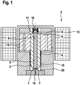
Fig. 1 einen schematischen Längsschnitt durch ein erfindungsgemäßes Schalt- oder Druckregelventil gemäß einer ersten bevorzugten Ausführungsform, -
Fig. 2 einen schematischen Längsschnitt durch ein erfindungsgemäßes Schalt- oder Druckregelventil gemäß einer zweiten bevorzugten Ausführungsform, -
Fig. 3 einen schematischen Längsschnitt durch ein erfindungsgemäßes Schalt- oder Druckregelventil im Bereich seines Ventilsitzes und -
Fig. 4 einen schematischen Längsschnitt durch ein erfindungsgemäßes Schalt- oder Druckregelventil im Bereich seines Ventilsitzes als Variante zum Ventilsitz derFig. 3 .
-
Fig. 1 2 shows a schematic longitudinal section through an inventive switching or pressure regulating valve according to a first preferred embodiment, -
Fig. 2 2 shows a schematic longitudinal section through an inventive switching or pressure regulating valve according to a second preferred embodiment, -
Fig. 3 a schematic longitudinal section through an inventive switching or pressure control valve in the region of its valve seat and -
Fig. 4 a schematic longitudinal section through an inventive switching or pressure control valve in the region of its valve seat as a variant of the valve seatFig. 3 ,
Das in der
Das dargestellte Druckregelventil ist als druckausgeglichenes Ventil ausgeführt. Es umfasst ein mit einem Ventilsitz 1 zusammenwirkendes, hubbewegliches Ventilschließelement 2 sowie einen Aktor 3, mittels dessen das Ventilschließelement 2 direkt betätigbar ist. Bei dem Aktor 3 handelt es sich um einen Magnetaktor mit einer Magnetspule 13 zur Einwirkung auf einen mit dem Ventilschließelement 2 verbundenen Anker 14, der vorliegend als Tauchanker ausgebildet ist. Bei einer Bestromung der Magnetspule 13 bildet sich ein Magnetfeld aus, dessen Magnetkraft den Anker 14 in Richtung des Ventilsitzes 1 zieht. Dabei drückt der Anker 14 das Ventilschließelement 2 gegen den Ventilsitz 1. Zum Öffnen des Ventils wird die Bestromung der Magnetspule 13 unterbrochen, so dass eine das Ventilschließelement 2 in Öffnungsrichtung beaufschlagende Ventilfeder 4 das Ventil zu öffnen vermag. Die Ventilfeder 4 ist hierzu einerseits an der dem Ventilsitz 1 zugewandten Stirnfläche des Ankers 14 und andererseits an einer Stirnfläche einer das Ventilschließelement 2 bereichsweise umgebenden Führungshülse 15 abgestützt, die der Führung des Ventilschließelements 2 dient. Die Führungshülse 15 wird von dem Ablaufkanal 20 durchsetzt.The pressure control valve shown is designed as a pressure-balanced valve. It comprises a
Um neben der Druckregelfunktion ferner eine Druckhaltefunktion zu realisieren, ist im Ventilschließelement 2 eine zentrale Bohrung 6 ausgebildet, in der ein Druckstift 5 bereichsweise aufgenommen und geführt ist. Der Druckstift 5 überragt an seinem dem Ventilsitz 1 abgewandten Ende das Ventilschließelement 2 und bildet einen Bundabschnitt 11 aus, an dem eine Druckhaltefeder 8 abgestützt ist. Das andere Ende der Druckhaltefeder 8 ist gehäuseseitig abgestützt. Die Federkraft der Druckhaltefeder 8 spannt den Druckstift 5 in Richtung eines Dichtsitzes 7 vor, der radial innen liegend unmittelbar an den Ventilsitz 1 angrenzt und von dem Zulaufkanal 16 durchsetzt wird. Liegt der Druckstift 5 am Dichtsitz 7 an (siehe
Beim Abheben vom Dichtsitz 7 bewegt sich der Druckstift 5 in Richtung eines Gehäuseanschlags 9, bis eine am Druckstift 5 ausgebildete Anschlagfläche 10 zur Anlage am Gehäuseanschlag 9 kommt. In dieser Lage nimmt der Druckstift 5 an der Druckregelfunktion des Ventils nicht mehr teil. Denn das Ventilschließelement 2 vermag unbeeinflusst zu öffnen und zu schließen.When lifting off the sealing
Eine Abwandlung des Druckregelventils der
Im Übrigen entspricht das Druckregelventil der
Die
Zur Ausbildung des Dichtsitzes 7 ist in der
Bei der Variante der
Die Erfindung ist nicht auf die dargestellten Ausführungsformen eines Druckregelventils beschränkt, sondern grundsätzlich auf alle druckausgeglichenen oder nahezu druckausgeglichenen Ventile innerhalb eines Kraftstoffeinspritzsystems, insbesondere eines Common-Rail-Einspritzsystems, anwendbar.The invention is not limited to the illustrated embodiments of a pressure control valve, but basically applicable to all pressure-balanced or almost pressure-balanced valves within a fuel injection system, in particular a common rail injection system.
Claims (9)
- Switching or pressure-regulating valve for a fuel injection system, in particular a common-rail injection system, comprising a valve closure element (2) which is able to perform stroke movements and interacts with a valve seat (1) and is able to be actuated by means of an actuator (3) and is acted on by the spring force of a valve spring (4) counter to the direction of action of the actuator (3), also comprising a pressure pin (5) which is received at least regionally in a central bore (6) of the valve closure element (2) and is acted on by the spring force of a pressure-maintaining spring (8) in the direction of a sealing seat (7), wherein the pressure pin (5) is able to bear against the sealing seat (7) and the pressure pin (5) and the sealing seat (7) thus form a pressure-maintaining valve, wherein the spring force of the valve spring (4) acts on the valve closure element (2) in the opening direction,
characterized in that the sealing seat (7) directly adjoins, radially on the inside, the valve seat (1) and is passed through by an inflow duct (16). - Switching or pressure-regulating valve according to Claim 1,
characterized in that the pressure-maintaining spring (8) is supported both against the pressure pin (5), preferably against a collar portion (11) of the pressure pin (5), and on the housing side. - Switching or pressure-regulating valve according to Claim 1,
characterized in that the pressure-maintaining spring (8) is supported both against the pressure pin (5), preferably against a collar portion (11) of the pressure pin (5), and against the valve closure element (2), preferably indirectly via a spring plate (12) which is connected to the valve closure element (2). - Switching or pressure-regulating valve according to Claim 1 or 2,
characterized in that the central bore (6) of the valve closure element (2) is in the form of a stepped bore and has a portion with an enlarged inner diameter for receiving the pressure-maintaining spring (8) and/or the collar portion (11) of the pressure pin (5) and/or the spring plate (12). - Switching or pressure-regulating valve according to one of the preceding claims,
characterized in that the pressure pin (5) has at its end facing away from the sealing seat (7) a stop surface (10) which interacts with a housing stop (9) . - Switching or pressure-regulating valve according to one of the preceding claims,
characterized in that the valve closure element (2) is in the form of a hollow needle which is preferably formed in a conically tapering manner at its end facing the valve seat (1). - Switching or pressure-regulating valve according to one of the preceding claims,
characterized in that the valve seat (1) is of conical form. - Switching or pressure-regulating valve according to one of the preceding claims,
characterized in that the sealing seat (7) is in the form of a flat seat or conical seat and/or is formed in a manner directly adjoining the valve seat (1). - Switching or pressure-regulating valve according to one of the preceding claims,
characterized in that the actuator (3) is a magnet actuator and comprises a magnet coil (13) for acting on an armature (14) which is coupled or is able to be coupled to the valve closure element (2).
Applications Claiming Priority (1)
| Application Number | Priority Date | Filing Date | Title |
|---|---|---|---|
| DE102014225323.3A DE102014225323A1 (en) | 2014-12-09 | 2014-12-09 | Shift or pressure control valve for a fuel injection system |
Publications (2)
| Publication Number | Publication Date |
|---|---|
| EP3032090A1 EP3032090A1 (en) | 2016-06-15 |
| EP3032090B1 true EP3032090B1 (en) | 2020-01-08 |
Family
ID=54365153
Family Applications (1)
| Application Number | Title | Priority Date | Filing Date |
|---|---|---|---|
| EP15192577.3A Active EP3032090B1 (en) | 2014-12-09 | 2015-11-02 | Switching or pressure control valve for a fuel injection system |
Country Status (2)
| Country | Link |
|---|---|
| EP (1) | EP3032090B1 (en) |
| DE (1) | DE102014225323A1 (en) |
Families Citing this family (1)
| Publication number | Priority date | Publication date | Assignee | Title |
|---|---|---|---|---|
| DE102021206328A1 (en) * | 2021-06-21 | 2022-12-22 | Robert Bosch Gesellschaft mit beschränkter Haftung | Gas storage device, gas supply system and gas engine |
Citations (1)
| Publication number | Priority date | Publication date | Assignee | Title |
|---|---|---|---|---|
| JPH07167012A (en) * | 1993-12-17 | 1995-07-04 | Zexel Corp | Fuel injection device |
Family Cites Families (8)
| Publication number | Priority date | Publication date | Assignee | Title |
|---|---|---|---|---|
| DE4438336A1 (en) * | 1994-10-27 | 1996-05-02 | Bosch Gmbh Robert | Solenoid valve with pressure limitation for slip-controlled motor vehicle braking systems |
| GB9616521D0 (en) * | 1996-08-06 | 1996-09-25 | Lucas Ind Plc | Injector |
| DE102006049885A1 (en) * | 2006-10-23 | 2008-04-24 | Robert Bosch Gmbh | Fuel injector i.e. common rail injector, for internal-combustion engine, has valve seat designed as flat seat with even valve seat surface, and casing resting on seat surface with front-sided circulating edge when control valve is closed |
| DE102008000907A1 (en) * | 2008-04-01 | 2009-10-08 | Robert Bosch Gmbh | Solenoid valve with multipart anchor without armature guide |
| DE102008002717A1 (en) * | 2008-06-27 | 2010-01-14 | Robert Bosch Gmbh | Fuel injector with two-part magnet armature |
| DE102009000284A1 (en) | 2009-01-19 | 2010-07-22 | Robert Bosch Gmbh | Fuel injection valve device for injection of fluid from high pressure chamber into combustion chamber of internal combustion engine, has retaining body interrupting connection so that retaining pressure is larger than return pressure |
| DE102009027841A1 (en) | 2009-07-20 | 2011-01-27 | Robert Bosch Gmbh | Fuel injection valve |
| DE102010043097A1 (en) | 2010-10-29 | 2012-05-03 | Robert Bosch Gmbh | Pressure control valve |
-
2014
- 2014-12-09 DE DE102014225323.3A patent/DE102014225323A1/en not_active Withdrawn
-
2015
- 2015-11-02 EP EP15192577.3A patent/EP3032090B1/en active Active
Patent Citations (1)
| Publication number | Priority date | Publication date | Assignee | Title |
|---|---|---|---|---|
| JPH07167012A (en) * | 1993-12-17 | 1995-07-04 | Zexel Corp | Fuel injection device |
Also Published As
| Publication number | Publication date |
|---|---|
| DE102014225323A1 (en) | 2016-06-09 |
| EP3032090A1 (en) | 2016-06-15 |
Similar Documents
| Publication | Publication Date | Title |
|---|---|---|
| EP3478957B1 (en) | Valve for injecting gaseous fuel | |
| EP2531715B1 (en) | Control valve assembly of a fuel injector | |
| EP2462335B1 (en) | Device for high-pressure fuel injection | |
| EP2454467B1 (en) | Valve arrangement | |
| WO2014000961A1 (en) | Fuel injector having a magnetic actuator | |
| EP2743493B1 (en) | Fuel injector | |
| WO2016034402A1 (en) | Proportional valve that can be actuated electromagnetically | |
| EP2278152B1 (en) | Fuel injection valve | |
| EP2494182B1 (en) | Fuel injection device | |
| EP3032090B1 (en) | Switching or pressure control valve for a fuel injection system | |
| EP2733345A1 (en) | Pressure control valve for a high pressure storage tank of a combustion engine | |
| EP3387247B1 (en) | Electromagnetically actuatable inlet valve and high-pressure pump having an inlet valve | |
| EP3420257B1 (en) | Solenoid valve | |
| EP3365551B1 (en) | Electromagnetically operable inlet valve and high-pressure pump having an inlet valve | |
| DE102006047935A1 (en) | Fuel injector for an internal combustion engine | |
| WO2017108343A1 (en) | Electromagnetically actuatable inlet valve and high-pressure pump having an inlet valve | |
| DE102009000284A1 (en) | Fuel injection valve device for injection of fluid from high pressure chamber into combustion chamber of internal combustion engine, has retaining body interrupting connection so that retaining pressure is larger than return pressure | |
| EP3423717B1 (en) | Electromagnetically actuatable inlet valve and high-pressure pump comprising an inlet valve | |
| DE102015214816A1 (en) | High pressure arrangement | |
| WO2009027215A1 (en) | Control valve for a fuel injector | |
| DE102008002605A1 (en) | Direct operated fuel injector | |
| DE102014211469A1 (en) | Nozzle assembly for a fuel injector and fuel injector | |
| DE102019220172A1 (en) | Fuel injector for an internal combustion engine | |
| WO2019197067A1 (en) | Electromagnetically actuatable inlet valve and high-pressure pump having an inlet valve | |
| EP2204570A1 (en) | Fuel injector |
Legal Events
| Date | Code | Title | Description |
|---|---|---|---|
| PUAI | Public reference made under article 153(3) epc to a published international application that has entered the european phase |
Free format text: ORIGINAL CODE: 0009012 |
|
| AK | Designated contracting states |
Kind code of ref document: A1 Designated state(s): AL AT BE BG CH CY CZ DE DK EE ES FI FR GB GR HR HU IE IS IT LI LT LU LV MC MK MT NL NO PL PT RO RS SE SI SK SM TR |
|
| AX | Request for extension of the european patent |
Extension state: BA ME |
|
| STAA | Information on the status of an ep patent application or granted ep patent |
Free format text: STATUS: REQUEST FOR EXAMINATION WAS MADE |
|
| 17P | Request for examination filed |
Effective date: 20161215 |
|
| RBV | Designated contracting states (corrected) |
Designated state(s): AL AT BE BG CH CY CZ DE DK EE ES FI FR GB GR HR HU IE IS IT LI LT LU LV MC MK MT NL NO PL PT RO RS SE SI SK SM TR |
|
| STAA | Information on the status of an ep patent application or granted ep patent |
Free format text: STATUS: EXAMINATION IS IN PROGRESS |
|
| 17Q | First examination report despatched |
Effective date: 20180810 |
|
| GRAP | Despatch of communication of intention to grant a patent |
Free format text: ORIGINAL CODE: EPIDOSNIGR1 |
|
| STAA | Information on the status of an ep patent application or granted ep patent |
Free format text: STATUS: GRANT OF PATENT IS INTENDED |
|
| INTG | Intention to grant announced |
Effective date: 20190521 |
|
| GRAS | Grant fee paid |
Free format text: ORIGINAL CODE: EPIDOSNIGR3 |
|
| GRAA | (expected) grant |
Free format text: ORIGINAL CODE: 0009210 |
|
| STAA | Information on the status of an ep patent application or granted ep patent |
Free format text: STATUS: THE PATENT HAS BEEN GRANTED |
|
| AK | Designated contracting states |
Kind code of ref document: B1 Designated state(s): AL AT BE BG CH CY CZ DE DK EE ES FI FR GB GR HR HU IE IS IT LI LT LU LV MC MK MT NL NO PL PT RO RS SE SI SK SM TR |
|
| REG | Reference to a national code |
Ref country code: GB Ref legal event code: FG4D Free format text: NOT ENGLISH |
|
| REG | Reference to a national code |
Ref country code: CH Ref legal event code: EP |
|
| REG | Reference to a national code |
Ref country code: DE Ref legal event code: R096 Ref document number: 502015011446 Country of ref document: DE |
|
| REG | Reference to a national code |
Ref country code: IE Ref legal event code: FG4D Free format text: LANGUAGE OF EP DOCUMENT: GERMAN |
|
| REG | Reference to a national code |
Ref country code: AT Ref legal event code: REF Ref document number: 1223029 Country of ref document: AT Kind code of ref document: T Effective date: 20200215 |
|
| RAP2 | Party data changed (patent owner data changed or rights of a patent transferred) |
Owner name: ROBERT BOSCH GMBH |
|
| REG | Reference to a national code |
Ref country code: NL Ref legal event code: MP Effective date: 20200108 |
|
| REG | Reference to a national code |
Ref country code: LT Ref legal event code: MG4D |
|
| PG25 | Lapsed in a contracting state [announced via postgrant information from national office to epo] |
Ref country code: NO Free format text: LAPSE BECAUSE OF FAILURE TO SUBMIT A TRANSLATION OF THE DESCRIPTION OR TO PAY THE FEE WITHIN THE PRESCRIBED TIME-LIMIT Effective date: 20200408 Ref country code: LT Free format text: LAPSE BECAUSE OF FAILURE TO SUBMIT A TRANSLATION OF THE DESCRIPTION OR TO PAY THE FEE WITHIN THE PRESCRIBED TIME-LIMIT Effective date: 20200108 Ref country code: NL Free format text: LAPSE BECAUSE OF FAILURE TO SUBMIT A TRANSLATION OF THE DESCRIPTION OR TO PAY THE FEE WITHIN THE PRESCRIBED TIME-LIMIT Effective date: 20200108 Ref country code: PT Free format text: LAPSE BECAUSE OF FAILURE TO SUBMIT A TRANSLATION OF THE DESCRIPTION OR TO PAY THE FEE WITHIN THE PRESCRIBED TIME-LIMIT Effective date: 20200531 Ref country code: FI Free format text: LAPSE BECAUSE OF FAILURE TO SUBMIT A TRANSLATION OF THE DESCRIPTION OR TO PAY THE FEE WITHIN THE PRESCRIBED TIME-LIMIT Effective date: 20200108 Ref country code: RS Free format text: LAPSE BECAUSE OF FAILURE TO SUBMIT A TRANSLATION OF THE DESCRIPTION OR TO PAY THE FEE WITHIN THE PRESCRIBED TIME-LIMIT Effective date: 20200108 |
|
| PG25 | Lapsed in a contracting state [announced via postgrant information from national office to epo] |
Ref country code: GR Free format text: LAPSE BECAUSE OF FAILURE TO SUBMIT A TRANSLATION OF THE DESCRIPTION OR TO PAY THE FEE WITHIN THE PRESCRIBED TIME-LIMIT Effective date: 20200409 Ref country code: HR Free format text: LAPSE BECAUSE OF FAILURE TO SUBMIT A TRANSLATION OF THE DESCRIPTION OR TO PAY THE FEE WITHIN THE PRESCRIBED TIME-LIMIT Effective date: 20200108 Ref country code: BG Free format text: LAPSE BECAUSE OF FAILURE TO SUBMIT A TRANSLATION OF THE DESCRIPTION OR TO PAY THE FEE WITHIN THE PRESCRIBED TIME-LIMIT Effective date: 20200408 Ref country code: LV Free format text: LAPSE BECAUSE OF FAILURE TO SUBMIT A TRANSLATION OF THE DESCRIPTION OR TO PAY THE FEE WITHIN THE PRESCRIBED TIME-LIMIT Effective date: 20200108 Ref country code: IS Free format text: LAPSE BECAUSE OF FAILURE TO SUBMIT A TRANSLATION OF THE DESCRIPTION OR TO PAY THE FEE WITHIN THE PRESCRIBED TIME-LIMIT Effective date: 20200508 Ref country code: SE Free format text: LAPSE BECAUSE OF FAILURE TO SUBMIT A TRANSLATION OF THE DESCRIPTION OR TO PAY THE FEE WITHIN THE PRESCRIBED TIME-LIMIT Effective date: 20200108 |
|
| REG | Reference to a national code |
Ref country code: DE Ref legal event code: R097 Ref document number: 502015011446 Country of ref document: DE |
|
| PG25 | Lapsed in a contracting state [announced via postgrant information from national office to epo] |
Ref country code: CZ Free format text: LAPSE BECAUSE OF FAILURE TO SUBMIT A TRANSLATION OF THE DESCRIPTION OR TO PAY THE FEE WITHIN THE PRESCRIBED TIME-LIMIT Effective date: 20200108 Ref country code: RO Free format text: LAPSE BECAUSE OF FAILURE TO SUBMIT A TRANSLATION OF THE DESCRIPTION OR TO PAY THE FEE WITHIN THE PRESCRIBED TIME-LIMIT Effective date: 20200108 Ref country code: SM Free format text: LAPSE BECAUSE OF FAILURE TO SUBMIT A TRANSLATION OF THE DESCRIPTION OR TO PAY THE FEE WITHIN THE PRESCRIBED TIME-LIMIT Effective date: 20200108 Ref country code: EE Free format text: LAPSE BECAUSE OF FAILURE TO SUBMIT A TRANSLATION OF THE DESCRIPTION OR TO PAY THE FEE WITHIN THE PRESCRIBED TIME-LIMIT Effective date: 20200108 Ref country code: DK Free format text: LAPSE BECAUSE OF FAILURE TO SUBMIT A TRANSLATION OF THE DESCRIPTION OR TO PAY THE FEE WITHIN THE PRESCRIBED TIME-LIMIT Effective date: 20200108 Ref country code: ES Free format text: LAPSE BECAUSE OF FAILURE TO SUBMIT A TRANSLATION OF THE DESCRIPTION OR TO PAY THE FEE WITHIN THE PRESCRIBED TIME-LIMIT Effective date: 20200108 Ref country code: SK Free format text: LAPSE BECAUSE OF FAILURE TO SUBMIT A TRANSLATION OF THE DESCRIPTION OR TO PAY THE FEE WITHIN THE PRESCRIBED TIME-LIMIT Effective date: 20200108 |
|
| PLBE | No opposition filed within time limit |
Free format text: ORIGINAL CODE: 0009261 |
|
| STAA | Information on the status of an ep patent application or granted ep patent |
Free format text: STATUS: NO OPPOSITION FILED WITHIN TIME LIMIT |
|
| 26N | No opposition filed |
Effective date: 20201009 |
|
| PG25 | Lapsed in a contracting state [announced via postgrant information from national office to epo] |
Ref country code: IT Free format text: LAPSE BECAUSE OF FAILURE TO SUBMIT A TRANSLATION OF THE DESCRIPTION OR TO PAY THE FEE WITHIN THE PRESCRIBED TIME-LIMIT Effective date: 20200108 |
|
| PG25 | Lapsed in a contracting state [announced via postgrant information from national office to epo] |
Ref country code: PL Free format text: LAPSE BECAUSE OF FAILURE TO SUBMIT A TRANSLATION OF THE DESCRIPTION OR TO PAY THE FEE WITHIN THE PRESCRIBED TIME-LIMIT Effective date: 20200108 Ref country code: SI Free format text: LAPSE BECAUSE OF FAILURE TO SUBMIT A TRANSLATION OF THE DESCRIPTION OR TO PAY THE FEE WITHIN THE PRESCRIBED TIME-LIMIT Effective date: 20200108 |
|
| PG25 | Lapsed in a contracting state [announced via postgrant information from national office to epo] |
Ref country code: MC Free format text: LAPSE BECAUSE OF FAILURE TO SUBMIT A TRANSLATION OF THE DESCRIPTION OR TO PAY THE FEE WITHIN THE PRESCRIBED TIME-LIMIT Effective date: 20200108 |
|
| REG | Reference to a national code |
Ref country code: CH Ref legal event code: PL |
|
| GBPC | Gb: european patent ceased through non-payment of renewal fee |
Effective date: 20201102 |
|
| PG25 | Lapsed in a contracting state [announced via postgrant information from national office to epo] |
Ref country code: LU Free format text: LAPSE BECAUSE OF NON-PAYMENT OF DUE FEES Effective date: 20201102 |
|
| REG | Reference to a national code |
Ref country code: BE Ref legal event code: MM Effective date: 20201130 |
|
| PG25 | Lapsed in a contracting state [announced via postgrant information from national office to epo] |
Ref country code: CH Free format text: LAPSE BECAUSE OF NON-PAYMENT OF DUE FEES Effective date: 20201130 Ref country code: LI Free format text: LAPSE BECAUSE OF NON-PAYMENT OF DUE FEES Effective date: 20201130 |
|
| PG25 | Lapsed in a contracting state [announced via postgrant information from national office to epo] |
Ref country code: FR Free format text: LAPSE BECAUSE OF NON-PAYMENT OF DUE FEES Effective date: 20201130 Ref country code: IE Free format text: LAPSE BECAUSE OF NON-PAYMENT OF DUE FEES Effective date: 20201102 |
|
| PG25 | Lapsed in a contracting state [announced via postgrant information from national office to epo] |
Ref country code: GB Free format text: LAPSE BECAUSE OF NON-PAYMENT OF DUE FEES Effective date: 20201102 |
|
| REG | Reference to a national code |
Ref country code: AT Ref legal event code: MM01 Ref document number: 1223029 Country of ref document: AT Kind code of ref document: T Effective date: 20201102 |
|
| PG25 | Lapsed in a contracting state [announced via postgrant information from national office to epo] |
Ref country code: AT Free format text: LAPSE BECAUSE OF NON-PAYMENT OF DUE FEES Effective date: 20201102 |
|
| PG25 | Lapsed in a contracting state [announced via postgrant information from national office to epo] |
Ref country code: TR Free format text: LAPSE BECAUSE OF FAILURE TO SUBMIT A TRANSLATION OF THE DESCRIPTION OR TO PAY THE FEE WITHIN THE PRESCRIBED TIME-LIMIT Effective date: 20200108 Ref country code: MT Free format text: LAPSE BECAUSE OF FAILURE TO SUBMIT A TRANSLATION OF THE DESCRIPTION OR TO PAY THE FEE WITHIN THE PRESCRIBED TIME-LIMIT Effective date: 20200108 Ref country code: CY Free format text: LAPSE BECAUSE OF FAILURE TO SUBMIT A TRANSLATION OF THE DESCRIPTION OR TO PAY THE FEE WITHIN THE PRESCRIBED TIME-LIMIT Effective date: 20200108 |
|
| PG25 | Lapsed in a contracting state [announced via postgrant information from national office to epo] |
Ref country code: MK Free format text: LAPSE BECAUSE OF FAILURE TO SUBMIT A TRANSLATION OF THE DESCRIPTION OR TO PAY THE FEE WITHIN THE PRESCRIBED TIME-LIMIT Effective date: 20200108 Ref country code: AL Free format text: LAPSE BECAUSE OF FAILURE TO SUBMIT A TRANSLATION OF THE DESCRIPTION OR TO PAY THE FEE WITHIN THE PRESCRIBED TIME-LIMIT Effective date: 20200108 |
|
| PG25 | Lapsed in a contracting state [announced via postgrant information from national office to epo] |
Ref country code: BE Free format text: LAPSE BECAUSE OF NON-PAYMENT OF DUE FEES Effective date: 20201130 |
|
| PGFP | Annual fee paid to national office [announced via postgrant information from national office to epo] |
Ref country code: DE Payment date: 20230124 Year of fee payment: 8 |
|
| PGFP | Annual fee paid to national office [announced via postgrant information from national office to epo] |
Ref country code: DE Payment date: 20240123 Year of fee payment: 9 |