EP3032034A1 - Baffle insert, vane with a baffle insert, and corresponding method of manufacturing a vane - Google Patents
Baffle insert, vane with a baffle insert, and corresponding method of manufacturing a vane Download PDFInfo
- Publication number
- EP3032034A1 EP3032034A1 EP15189444.1A EP15189444A EP3032034A1 EP 3032034 A1 EP3032034 A1 EP 3032034A1 EP 15189444 A EP15189444 A EP 15189444A EP 3032034 A1 EP3032034 A1 EP 3032034A1
- Authority
- EP
- European Patent Office
- Prior art keywords
- vane
- baffle
- baffle body
- recited
- rib
- Prior art date
- Legal status (The legal status is an assumption and is not a legal conclusion. Google has not performed a legal analysis and makes no representation as to the accuracy of the status listed.)
- Granted
Links
Images


Classifications
-
- F—MECHANICAL ENGINEERING; LIGHTING; HEATING; WEAPONS; BLASTING
- F01—MACHINES OR ENGINES IN GENERAL; ENGINE PLANTS IN GENERAL; STEAM ENGINES
- F01D—NON-POSITIVE DISPLACEMENT MACHINES OR ENGINES, e.g. STEAM TURBINES
- F01D9/00—Stators
- F01D9/02—Nozzles; Nozzle boxes; Stator blades; Guide conduits, e.g. individual nozzles
- F01D9/04—Nozzles; Nozzle boxes; Stator blades; Guide conduits, e.g. individual nozzles forming ring or sector
- F01D9/041—Nozzles; Nozzle boxes; Stator blades; Guide conduits, e.g. individual nozzles forming ring or sector using blades
-
- F—MECHANICAL ENGINEERING; LIGHTING; HEATING; WEAPONS; BLASTING
- F01—MACHINES OR ENGINES IN GENERAL; ENGINE PLANTS IN GENERAL; STEAM ENGINES
- F01D—NON-POSITIVE DISPLACEMENT MACHINES OR ENGINES, e.g. STEAM TURBINES
- F01D25/00—Component parts, details, or accessories, not provided for in, or of interest apart from, other groups
- F01D25/08—Cooling; Heating; Heat-insulation
- F01D25/12—Cooling
-
- F—MECHANICAL ENGINEERING; LIGHTING; HEATING; WEAPONS; BLASTING
- F01—MACHINES OR ENGINES IN GENERAL; ENGINE PLANTS IN GENERAL; STEAM ENGINES
- F01D—NON-POSITIVE DISPLACEMENT MACHINES OR ENGINES, e.g. STEAM TURBINES
- F01D5/00—Blades; Blade-carrying members; Heating, heat-insulating, cooling or antivibration means on the blades or the members
- F01D5/12—Blades
- F01D5/14—Form or construction
- F01D5/18—Hollow blades, i.e. blades with cooling or heating channels or cavities; Heating, heat-insulating or cooling means on blades
- F01D5/187—Convection cooling
- F01D5/188—Convection cooling with an insert in the blade cavity to guide the cooling fluid, e.g. forming a separation wall
-
- F—MECHANICAL ENGINEERING; LIGHTING; HEATING; WEAPONS; BLASTING
- F01—MACHINES OR ENGINES IN GENERAL; ENGINE PLANTS IN GENERAL; STEAM ENGINES
- F01D—NON-POSITIVE DISPLACEMENT MACHINES OR ENGINES, e.g. STEAM TURBINES
- F01D5/00—Blades; Blade-carrying members; Heating, heat-insulating, cooling or antivibration means on the blades or the members
- F01D5/12—Blades
- F01D5/14—Form or construction
- F01D5/18—Hollow blades, i.e. blades with cooling or heating channels or cavities; Heating, heat-insulating or cooling means on blades
- F01D5/187—Convection cooling
- F01D5/188—Convection cooling with an insert in the blade cavity to guide the cooling fluid, e.g. forming a separation wall
- F01D5/189—Convection cooling with an insert in the blade cavity to guide the cooling fluid, e.g. forming a separation wall the insert having a tubular cross-section, e.g. airfoil shape
-
- F—MECHANICAL ENGINEERING; LIGHTING; HEATING; WEAPONS; BLASTING
- F01—MACHINES OR ENGINES IN GENERAL; ENGINE PLANTS IN GENERAL; STEAM ENGINES
- F01D—NON-POSITIVE DISPLACEMENT MACHINES OR ENGINES, e.g. STEAM TURBINES
- F01D9/00—Stators
- F01D9/02—Nozzles; Nozzle boxes; Stator blades; Guide conduits, e.g. individual nozzles
-
- F—MECHANICAL ENGINEERING; LIGHTING; HEATING; WEAPONS; BLASTING
- F05—INDEXING SCHEMES RELATING TO ENGINES OR PUMPS IN VARIOUS SUBCLASSES OF CLASSES F01-F04
- F05D—INDEXING SCHEME FOR ASPECTS RELATING TO NON-POSITIVE-DISPLACEMENT MACHINES OR ENGINES, GAS-TURBINES OR JET-PROPULSION PLANTS
- F05D2220/00—Application
- F05D2220/30—Application in turbines
- F05D2220/32—Application in turbines in gas turbines
-
- F—MECHANICAL ENGINEERING; LIGHTING; HEATING; WEAPONS; BLASTING
- F05—INDEXING SCHEMES RELATING TO ENGINES OR PUMPS IN VARIOUS SUBCLASSES OF CLASSES F01-F04
- F05D—INDEXING SCHEME FOR ASPECTS RELATING TO NON-POSITIVE-DISPLACEMENT MACHINES OR ENGINES, GAS-TURBINES OR JET-PROPULSION PLANTS
- F05D2230/00—Manufacture
- F05D2230/20—Manufacture essentially without removing material
- F05D2230/23—Manufacture essentially without removing material by permanently joining parts together
- F05D2230/232—Manufacture essentially without removing material by permanently joining parts together by welding
-
- F—MECHANICAL ENGINEERING; LIGHTING; HEATING; WEAPONS; BLASTING
- F05—INDEXING SCHEMES RELATING TO ENGINES OR PUMPS IN VARIOUS SUBCLASSES OF CLASSES F01-F04
- F05D—INDEXING SCHEME FOR ASPECTS RELATING TO NON-POSITIVE-DISPLACEMENT MACHINES OR ENGINES, GAS-TURBINES OR JET-PROPULSION PLANTS
- F05D2230/00—Manufacture
- F05D2230/60—Assembly methods
-
- F—MECHANICAL ENGINEERING; LIGHTING; HEATING; WEAPONS; BLASTING
- F05—INDEXING SCHEMES RELATING TO ENGINES OR PUMPS IN VARIOUS SUBCLASSES OF CLASSES F01-F04
- F05D—INDEXING SCHEME FOR ASPECTS RELATING TO NON-POSITIVE-DISPLACEMENT MACHINES OR ENGINES, GAS-TURBINES OR JET-PROPULSION PLANTS
- F05D2240/00—Components
- F05D2240/10—Stators
- F05D2240/12—Fluid guiding means, e.g. vanes
-
- F—MECHANICAL ENGINEERING; LIGHTING; HEATING; WEAPONS; BLASTING
- F05—INDEXING SCHEMES RELATING TO ENGINES OR PUMPS IN VARIOUS SUBCLASSES OF CLASSES F01-F04
- F05D—INDEXING SCHEME FOR ASPECTS RELATING TO NON-POSITIVE-DISPLACEMENT MACHINES OR ENGINES, GAS-TURBINES OR JET-PROPULSION PLANTS
- F05D2240/00—Components
- F05D2240/10—Stators
- F05D2240/12—Fluid guiding means, e.g. vanes
- F05D2240/126—Baffles or ribs
-
- F—MECHANICAL ENGINEERING; LIGHTING; HEATING; WEAPONS; BLASTING
- F05—INDEXING SCHEMES RELATING TO ENGINES OR PUMPS IN VARIOUS SUBCLASSES OF CLASSES F01-F04
- F05D—INDEXING SCHEME FOR ASPECTS RELATING TO NON-POSITIVE-DISPLACEMENT MACHINES OR ENGINES, GAS-TURBINES OR JET-PROPULSION PLANTS
- F05D2260/00—Function
- F05D2260/20—Heat transfer, e.g. cooling
- F05D2260/201—Heat transfer, e.g. cooling by impingement of a fluid
-
- F—MECHANICAL ENGINEERING; LIGHTING; HEATING; WEAPONS; BLASTING
- F05—INDEXING SCHEMES RELATING TO ENGINES OR PUMPS IN VARIOUS SUBCLASSES OF CLASSES F01-F04
- F05D—INDEXING SCHEME FOR ASPECTS RELATING TO NON-POSITIVE-DISPLACEMENT MACHINES OR ENGINES, GAS-TURBINES OR JET-PROPULSION PLANTS
- F05D2260/00—Function
- F05D2260/20—Heat transfer, e.g. cooling
- F05D2260/202—Heat transfer, e.g. cooling by film cooling
-
- Y—GENERAL TAGGING OF NEW TECHNOLOGICAL DEVELOPMENTS; GENERAL TAGGING OF CROSS-SECTIONAL TECHNOLOGIES SPANNING OVER SEVERAL SECTIONS OF THE IPC; TECHNICAL SUBJECTS COVERED BY FORMER USPC CROSS-REFERENCE ART COLLECTIONS [XRACs] AND DIGESTS
- Y02—TECHNOLOGIES OR APPLICATIONS FOR MITIGATION OR ADAPTATION AGAINST CLIMATE CHANGE
- Y02T—CLIMATE CHANGE MITIGATION TECHNOLOGIES RELATED TO TRANSPORTATION
- Y02T50/00—Aeronautics or air transport
- Y02T50/60—Efficient propulsion technologies, e.g. for aircraft
Definitions
- the present disclosure relates to vanes, and more particularly to vane assemblies for gas turbine engines, for example.
- turbomachines as in gas turbine engines, include multiple stages of rotor blades and vanes to condition and guide fluid flow through the compressor and/or turbine sections. Due to the high temperatures in the turbine section, turbine vanes are often cooled with cooling air ducted into an internal cavity of the vane through a vane platform. In order to reduce the amount of cooling air required to cool turbine vanes, space filling baffles can be provided in the vane cavity to reduce the cavity volume, thereby increasing Mach numbers and heat transfer coefficients for the cooling flow. Unfortunately, in certain vane designs, attachment hooks and rails cover up the cavity opening preventing baffles from being inserted radially into that cavity.
- a baffle insert for an airfoil includes a first baffle body extending from a first end to a second end along a longitudinal axis.
- the first baffle body includes a pair of opposing flanges.
- the baffle insert can include a second baffle body having a hollow interior for receiving the first baffle body.
- the hollow interior can include a longitudinally extending opening facing a lateral direction for sliding the first baffle body between a nested position and an expanded position relative to the second baffle body.
- the flanges of the first baffle body can anchor the first baffle body to the second baffle body in the expanded position.
- the first and second baffle bodies can include a plurality of impingement holes for supplying cooling air to a cavity of an airfoil.
- a vane in accordance with certain embodiments, includes a vane body extending from a root to an opposed tip along a longitudinal axis and first and second baffle bodies.
- the vane body defines a leading edge and a trailing edge, and a cavity defined between the leading edge, the trailing edge, the root and the tip.
- the vane body includes at least one vane rib defined between the leading edge and the trailing edge inside the cavity.
- the first baffle body is defined in one of a leading edge portion and a trailing edge portion of the cavity.
- the second baffle body is defined in a middle portion of the cavity.
- the vane rib can be a slotted vane rib having a longitudinal slot.
- a portion of the first baffle body can be defined between the longitudinal slot of the slotted vane rib.
- the flanges of the first baffle body can anchor the first baffle body within the longitudinal slot of the slotted vane rib.
- the vane can also include a weld joint between the first baffle body and the slotted vane rib.
- the vane body can include a plurality of filmholes for supplying cooling air to outside of the vane body.
- a vane as described above can be manufactured by a method including inserting a first baffle body into a vane opening defined in a vane body, sliding the first baffle body in one of a forward direction and an aft direction through a slotted rib of the vane body, and joining the first baffle body to the slotted rib of the vane body.
- the method can also include inserting a second baffle body into the vane opening and joining the second baffle body to another rib of the vane body.
- Inserting the first baffle body into the vane opening can include inserting the first baffle body into the vane opening while the first baffle body is nested within a second baffle body.
- Sliding the first baffle body in one of a forward direction and aft direction can include sliding the first baffle body through a longitudinally extending opening of the second baffle body from a nested position into an expanded position.
- the method can also include joining the second baffle body to a non-slotted rib of the vane body.
- FIG. 1 a cross-sectional side elevation view of an exemplary embodiment of a gas turbine engine accordance with the disclosure is shown in Fig. 1 and is designated generally by reference character 20.
- FIG. 2-11B Other embodiments of gas turbine engines in accordance with the disclosure, or aspects thereof, are provided in Figs. 2-11B , as will be described.
- Fig. 1 schematically illustrates a gas turbine engine 20.
- the gas turbine engine 20 is disclosed herein as a two-spool turbofan that generally incorporates a fan section 22, a compressor section 24, a combustor section 26 and a turbine section 28.
- Alternative engines might include an augmentor section (not shown) among other systems or features.
- the fan section 22 drives air along a bypass flow path B in a bypass duct defined within a fan case 15, while the compressor section 24 drives air along a core flow path C for compression and communication into the combustor section 26 then expansion through the turbine section 28.
- the exemplary engine 20 generally includes a low speed spool 30 and a high speed spool 32 mounted for rotation about an engine central axis X relative to an engine static structure 36 via several bearing systems 38. It should be understood that various bearing systems 38 at various locations may alternatively or additionally be provided, and the location of bearing systems 38 may be varied as appropriate to the application.
- the low speed spool 30 generally includes an inner shaft 40 that interconnects a fan 42, a low pressure compressor 44 and a low pressure turbine 46.
- the inner shaft 40 is connected to the fan 42 through a speed change mechanism, which in exemplary gas turbine engine 20 is illustrated as a geared architecture 48 to drive the fan 42 at a lower speed than the low speed spool 30.
- the high speed spool 32 includes an outer shaft 50 that interconnects a high pressure compressor 52 and high pressure turbine 54.
- a combustor 56 is arranged in exemplary gas turbine 20 between the high pressure compressor 52 and the high pressure turbine 54.
- a mid-turbine frame 58 of the engine static structure 36 is arranged generally between the high pressure turbine 54 and the low pressure turbine 46.
- the mid-turbine frame 58 further supports bearing systems 38 in the turbine section 28.
- the inner shaft 40 and the outer shaft 50 are concentric and rotate via bearing systems 38 about the engine central axis X which is collinear with their longitudinal axes.
- each of the positions of the fan section 22, compressor section 24, combustor section 26, turbine section 28, and fan drive gear system 48 may be varied.
- gear system 48 may be located aft of combustor section 26 or even aft of turbine section 28, and fan section 22 may be positioned forward or aft of the location of gear system 48.
- the engine 20 in one example is a high-bypass geared aircraft engine.
- the engine 20 bypass ratio is greater than about six (6), with an example embodiment being greater than about ten (10)
- the geared architecture 48 is an epicyclic gear train, such as a planetary gear system or other gear system, with a gear reduction ratio of greater than about 2.3
- the low pressure turbine 46 has a pressure ratio that is greater than about five.
- the engine 20 bypass ratio is greater than about ten (10:1)
- the fan diameter is significantly larger than that of the low pressure compressor 44
- the low pressure turbine 46 has a pressure ratio that is greater than about five 5:1.
- Low pressure turbine 46 pressure ratio is pressure measured prior to inlet of low pressure turbine 46 as related to the pressure at the outlet of the low pressure turbine 46 prior to an exhaust nozzle.
- the geared architecture 48 may be an epicycle gear train, such as a planetary gear system or other gear system, with a gear reduction ratio of greater than about 2.3:1. It should be understood, however, that the above parameters are only exemplary of one embodiment of a geared architecture engine and that the present disclosure is applicable to other gas turbine engines including direct drive turbofans.
- combustor section 26 and turbine section 28 both include vanes 100.
- Each vane 100 includes a vane body 102 extending from a root 104 to an opposed tip 106 along a longitudinal axis A.
- Vane body 100 defines a leading edge 105 and a trailing edge 107.
- a cavity 112 is defined between leading edge 105, trailing edge 107, root 104 and tip 106.
- first baffle bodies 108 are nested within hollow interiors 113 of respective second baffle bodies 110. Nested first and second baffle bodies, 108 and 110, respectively, are inserted into a vane opening 109 proximate to vane tip 106, e.g.
- first and second baffle bodies, 108 and 110 are inserted into a middle portion 122 of cavity 112. While first and second baffle bodies, 108 and 110, respectively, are described as being inserted into vane bodies, e.g. vane body 102, those having skill in the art will readily appreciate that first and second baffle bodies can also be used in other airfoils, e.g. blades, blade outer air seals, combustor panels, or the like.
- Figs. 3A-3B generally, it tends to be difficult to insert anything in the longitudinal direction, e.g. along longitudinal axis A, into leading and trailing edge portions 118 and 120, respectively, of cavity 112 due to rails 144, the outlines of which are shown schematically in Figs. 3A and 3B .
- Sliding baffle inserts for example, first baffle bodies 108, are configured to slide laterally from middle portion 122 into leading and trailing edge portions 118 and 120, respectively, as will be described below. This lateral sliding configuration avoids the difficulty of longitudinal insertion that rails 144 present.
- hollow interiors 113 of second baffle bodies 110 include an opening 126, e.g.
- Vane body 102 includes a vane rib 114 and two slotted vane ribs 116 defined between leading edge 105 and trailing edge 107 inside cavity 112. Slotted vane ribs 116 each include a longitudinal slot 130.
- First baffle bodies 108 each include a pair of opposing flanges 124 configured to anchor each baffle body 108 into a respective opening 126 of the second baffle bodies 110.
- first baffle bodies 108 are slid into respective forward and aft directions, indicated schematically in Figs. 4A and 4B with arrows.
- Each first baffle body 108 is laterally slidable through respective opening 126, then through respective longitudinal slot 130 of slotted vane rib 116 and into an expanded position, with respect to its respective second baffle body 110.
- Flanges 124 of each of first baffle bodies 108 anchor each first baffle body 108 to its respective second baffle body 110 in the expanded position.
- first baffle bodies 108 in an expanded position, one of first baffle bodies 108 is defined in a leading edge portion 118 of cavity 112 and the other of first baffle bodies 108 is defined in a trailing edge portion 120 of cavity 112. A portion of each first baffle body 108 is defined between a respective longitudinal slot 130 of a respective slotted vane rib 116.
- the second baffle bodies 110 are defined in a middle portion 122 of cavity 112. After the first baffle bodies 108 are slid into the expanded position, baffle bodies 108 are joined to respective slotted vane ribs 116, schematically shown by weld joint 132.
- second baffle bodies 110 are joined to respective opposing sides of the non-slotted vane rib 114, schematically shown by weld joints 134. While weld joints 132 and 134 are shown and described as being at specific locations, those skilled in the art will readily appreciate that there are a variety of suitable positions for a weld joint, for example first baffle body 108 could be joined directly to second baffle body 110. Further it will be appreciated that baffle bodies 108 and 110 can be joined by a variety of methods, such as spot and/or tack welding, and/or other suitable joining methods.
- first baffle bodies 208 are similar to first baffle bodies 108, however, they are not nested within second baffle bodies, e.g. second baffle bodies 110. Instead, first baffle bodies 208 are inserted into a vane opening 209 proximate to a vane tip 206, e.g. on the outer diameter platform 211. First baffle bodies 208 are inserted into a middle portion 222 of cavity 212. Second baffle bodies 210 have a closed cross-section instead of having an opening facing a lateral direction, e.g. opening 126.
- vane body 202 includes a vane rib 214 and two slotted vane ribs 216, similar to vane rib 114 and slotted vane ribs 116 described above.
- First baffle bodies 208 are also similar to first baffle bodies 108 in that first baffle bodies 208 each include a pair of opposing flanges 224. Flanges 224 of first baffle bodies 208, however, are configured to anchor each first baffle body 208 to longitudinal slot 230 of slotted vane rib 216, instead of a second baffle body, e.g. second baffle body 110, as will be described below.
- first baffle bodies 208 are slid into respective forward and aft directions, indicated schematically in Figs. 7A and 7B with arrows.
- Each first baffle body 208 is slid through a respective longitudinal slot 230 of a respective slotted vane rib 216 and into their respective leading and trailing edge portions 218 and 220, respectively, of cavity 212.
- Flanges 224 anchor each first baffle body 208 to a respective longitudinal slot 230 of a respective slotted vane rib 216.
- first baffle bodies 208 are similarly positioned to first baffle bodies 108, described above. After the first baffle bodies 208 are slid into position, each first baffle body 208 is joined to a respective slotted vane rib 216, schematically shown by weld joints 232, similar to weld joints 132, described above.
- second baffle bodies 210 are inserted into middle portions 222 of cavity 212 through vane opening 209 after first baffle bodies 208 are in position. As shown in Figs. 9A and 9B , second baffle bodies 210 are positioned similarly to second baffle bodies 110. Similar to second baffle bodies 110, second baffle bodies 210 are also joined to respective opposing sides of the non-slotted vane rib 214, schematically shown by weld joints 234.
- FIGs. 10A and 10B another embodiment of a vane 300 with nested first and second baffle bodies, 308 and 310, in an expanded position, is shown.
- Vane 300 is substantially similar to vane 100 except that a vane body 302 of vane 300 includes a plurality of filmholes 336 for supplying cooling air to outside of vane body 302.
- cooling air is introduced through a plurality of openings 338 on an outer diameter platform 311 proximate to a tip 306 of vane body 302.
- FIGs. 11A and 11B another embodiment of a vane 400 with nested first and second baffle bodies, 408 and 410, in an expanded position, is shown.
- Vane 400 is substantially similar to vane 300, except that first and second baffle bodies 408 and 410 include impingement holes 440.
- cooling air is introduced through a plurality of openings 438 on an outer diameter platform 411 proximate to a tip 406 of vane body 402.
- the openings 438 guide airflow into hollow interiors 415 and 413 of first and second baffle bodies 408 and 410, respectively.
- the air flows through each of first and second baffle bodies 408 and 410, respectively, and out through impingement holes 440 to airfoil cavity 412 or out through an exit 449 proximate to an inner diameter platform 443.
- impingement holes 440 From the impingement holes 440, the air flow is guided through cavity 412 and out of filmholes 436 or out through additional exits 447, also located proximate to inner diameter platform 443.
- This cooling airflow is indicated schematically by the arrows in Figs. 11A-11B .
- baffle inserts e.g. baffle bodies 108, 208, 308 and 408, described in the present disclosure allow baffle inserts to be in cavities that do not have line of sight access for insertion, e.g. leading edge and trailing edge portions. By sliding baffle inserts into areas generally not accessible, cavity area is reduced, which increases Mach numbers and heat transfer coefficients.
Landscapes
- Engineering & Computer Science (AREA)
- Mechanical Engineering (AREA)
- General Engineering & Computer Science (AREA)
- Turbine Rotor Nozzle Sealing (AREA)
Abstract
Description
- The present disclosure relates to vanes, and more particularly to vane assemblies for gas turbine engines, for example.
- Traditionally, turbomachines, as in gas turbine engines, include multiple stages of rotor blades and vanes to condition and guide fluid flow through the compressor and/or turbine sections. Due to the high temperatures in the turbine section, turbine vanes are often cooled with cooling air ducted into an internal cavity of the vane through a vane platform. In order to reduce the amount of cooling air required to cool turbine vanes, space filling baffles can be provided in the vane cavity to reduce the cavity volume, thereby increasing Mach numbers and heat transfer coefficients for the cooling flow. Unfortunately, in certain vane designs, attachment hooks and rails cover up the cavity opening preventing baffles from being inserted radially into that cavity.
- Such conventional methods and systems have generally been considered satisfactory for their intended purpose. However, there is still a need in the art for improved blades and vanes. The present disclosure provides a solution for these problems.
- A baffle insert for an airfoil includes a first baffle body extending from a first end to a second end along a longitudinal axis. The first baffle body includes a pair of opposing flanges.
- The baffle insert can include a second baffle body having a hollow interior for receiving the first baffle body. The hollow interior can include a longitudinally extending opening facing a lateral direction for sliding the first baffle body between a nested position and an expanded position relative to the second baffle body. The flanges of the first baffle body can anchor the first baffle body to the second baffle body in the expanded position. The first and second baffle bodies can include a plurality of impingement holes for supplying cooling air to a cavity of an airfoil.
- In accordance with certain embodiments, a vane includes a vane body extending from a root to an opposed tip along a longitudinal axis and first and second baffle bodies. The vane body defines a leading edge and a trailing edge, and a cavity defined between the leading edge, the trailing edge, the root and the tip. The vane body includes at least one vane rib defined between the leading edge and the trailing edge inside the cavity. The first baffle body is defined in one of a leading edge portion and a trailing edge portion of the cavity. The second baffle body is defined in a middle portion of the cavity.
- The vane rib can be a slotted vane rib having a longitudinal slot. A portion of the first baffle body can be defined between the longitudinal slot of the slotted vane rib. The flanges of the first baffle body can anchor the first baffle body within the longitudinal slot of the slotted vane rib. The vane can also include a weld joint between the first baffle body and the slotted vane rib. The vane body can include a plurality of filmholes for supplying cooling air to outside of the vane body.
- A vane as described above can be manufactured by a method including inserting a first baffle body into a vane opening defined in a vane body, sliding the first baffle body in one of a forward direction and an aft direction through a slotted rib of the vane body, and joining the first baffle body to the slotted rib of the vane body.
- The method can also include inserting a second baffle body into the vane opening and joining the second baffle body to another rib of the vane body. Inserting the first baffle body into the vane opening can include inserting the first baffle body into the vane opening while the first baffle body is nested within a second baffle body. Sliding the first baffle body in one of a forward direction and aft direction can include sliding the first baffle body through a longitudinally extending opening of the second baffle body from a nested position into an expanded position. The method can also include joining the second baffle body to a non-slotted rib of the vane body.
- These and other features of the systems and methods of the subject disclosure will become more readily apparent to those skilled in the art from the following detailed description of the preferred embodiments taken in conjunction with the drawings.
- So that those skilled in the art to which the subject disclosure appertains will readily understand how to make and use the devices and methods of the subject disclosure without undue experimentation, preferred embodiments thereof will be described in detail herein below, by way of example only and with reference to certain figures, wherein:
-
Fig. 1 is a schematic cross-sectional side elevation view of an exemplary embodiment of a gas turbine engine constructed in accordance with the present disclosure, showing locations of vanes; -
Fig. 2 is a schematic cross-sectional side elevation view of an exemplary embodiment of a vane having sliding baffle inserts constructed in accordance with the present disclosure, showing the insertion of the nested baffle bodies; -
Fig. 3A is a schematic cross-sectional side elevation view of the vane ofFig. 2 , showing the nested baffle bodies inserted in the vane; -
Fig. 3B is a schematic cross-sectional top plan view of the vane ofFig. 2 , showing the nested baffle bodies inserted in the vane; -
Fig. 4A is a schematic cross-sectional side elevation view of the vane ofFig. 2 , showing the first baffles bodies being slid into the leading and trailing edge portions of the cavity; -
Fig. 4B is a schematic cross-sectional top plan view of the vane ofFig. 2 , showing the first baffle bodies being slid into the leading and trailing edge portions of the cavity and the flanges of the first baffle bodies anchored respective openings of the second baffle bodies; -
Fig. 5 is a schematic cross-sectional side elevation view of another exemplary embodiment of a vane having sliding baffle inserts constructed in accordance with the present disclosure, showing the insertion of the first baffle bodies; -
Fig. 6A is a schematic cross-sectional side elevation view of the vane ofFig. 5 , showing the first baffle bodies inserted in the vane; -
Fig. 6B is a schematic cross-sectional top plan view of the vane ofFig. 5 , showing the first baffle bodies inserted in the vane; -
Fig. 7A is a schematic cross-sectional side elevation view of the vane ofFig. 5 , showing the first baffle bodies being slid into the leading and trailing edge portions of the cavity; -
Fig. 7B is a schematic cross-sectional top plan view of the vane ofFig. 5 , showing the first baffle bodies being slid into the leading and trailing edge portions of the cavity and the flanges of the first baffle bodies anchored to respective slotted vane ribs; -
Fig. 8 is a schematic cross-sectional side elevation view of the vane ofFig. 5 , showing the second baffle bodies being inserted into the vane after the first baffle bodies have been slid into place; -
Fig. 9A is a schematic cross-sectional side elevation view of the vane ofFig. 5 , showing the second baffle bodies inserted in the vane; -
Fig. 9B is a schematic cross-sectional top plan view of the vane ofFig. 5 , showing the second baffle bodies inserted in the vane; -
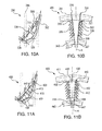
Fig. 10A is a schematic cross-sectional top plan view of another exemplary embodiment of a vane having sliding baffle inserts constructed in accordance with the present disclosure, schematically showing cooling airflow enter the vane and exit through filmholes; -
Fig. 10B is a schematic cross-sectional side elevation view of the vane ofFig. 10A , schematically showing the cooling airflow flow between the baffle bodies and the vane; -
Fig. 11A is a schematic cross-sectional top plan view of another exemplary embodiment of a vane having sliding baffle inserts constructed in accordance with the present disclosure, schematically showing cooling airflow entering first and second baffle bodies; and -
Fig. 11B is a schematic cross-sectional side elevation view of the vane ofFig. 11A , schematically showing the cooling airflow flow exit the baffle bodies through impingement holes, flow between the baffle bodies and the vane, and exit through filmholes in the vane. - Reference will now be made to the drawings wherein like reference numerals identify similar structural features or aspects of the subject disclosure. For purposes of explanation and illustration, and not limitation, a cross-sectional side elevation view of an exemplary embodiment of a gas turbine engine accordance with the disclosure is shown in
Fig. 1 and is designated generally byreference character 20. Other embodiments of gas turbine engines in accordance with the disclosure, or aspects thereof, are provided inFigs. 2-11B , as will be described. -
Fig. 1 schematically illustrates agas turbine engine 20. Thegas turbine engine 20 is disclosed herein as a two-spool turbofan that generally incorporates afan section 22, acompressor section 24, acombustor section 26 and aturbine section 28. Alternative engines might include an augmentor section (not shown) among other systems or features. Thefan section 22 drives air along a bypass flow path B in a bypass duct defined within afan case 15, while thecompressor section 24 drives air along a core flow path C for compression and communication into thecombustor section 26 then expansion through theturbine section 28. Although depicted as a two-spool turbofan gas turbine engine in the disclosed non-limiting embodiment, it should be understood that the concepts described herein are not limited to use with two-spool turbofans as the teachings may be applied to other types of turbine engines including three-spool architectures. - With continued reference to
Fig. 1 , theexemplary engine 20 generally includes alow speed spool 30 and ahigh speed spool 32 mounted for rotation about an engine central axis X relative to an enginestatic structure 36 viaseveral bearing systems 38. It should be understood that various bearingsystems 38 at various locations may alternatively or additionally be provided, and the location of bearingsystems 38 may be varied as appropriate to the application. - The
low speed spool 30 generally includes aninner shaft 40 that interconnects afan 42, alow pressure compressor 44 and alow pressure turbine 46. Theinner shaft 40 is connected to thefan 42 through a speed change mechanism, which in exemplarygas turbine engine 20 is illustrated as a gearedarchitecture 48 to drive thefan 42 at a lower speed than thelow speed spool 30. Thehigh speed spool 32 includes anouter shaft 50 that interconnects ahigh pressure compressor 52 andhigh pressure turbine 54. Acombustor 56 is arranged inexemplary gas turbine 20 between thehigh pressure compressor 52 and thehigh pressure turbine 54. Amid-turbine frame 58 of the enginestatic structure 36 is arranged generally between thehigh pressure turbine 54 and thelow pressure turbine 46. Themid-turbine frame 58 furthersupports bearing systems 38 in theturbine section 28. Theinner shaft 40 and theouter shaft 50 are concentric and rotate via bearingsystems 38 about the engine central axis X which is collinear with their longitudinal axes. - The core airflow is compressed by the
low pressure compressor 44 then thehigh pressure compressor 52, mixed and burned with fuel in thecombustor 56, then expanded over thehigh pressure turbine 54 andlow pressure turbine 46. Theturbines low speed spool 30 andhigh speed spool 32 in response to the expansion. It will be appreciated that each of the positions of thefan section 22,compressor section 24,combustor section 26,turbine section 28, and fandrive gear system 48 may be varied. For example,gear system 48 may be located aft ofcombustor section 26 or even aft ofturbine section 28, andfan section 22 may be positioned forward or aft of the location ofgear system 48. - The
engine 20 in one example is a high-bypass geared aircraft engine. In a further example, theengine 20 bypass ratio is greater than about six (6), with an example embodiment being greater than about ten (10), the gearedarchitecture 48 is an epicyclic gear train, such as a planetary gear system or other gear system, with a gear reduction ratio of greater than about 2.3 and thelow pressure turbine 46 has a pressure ratio that is greater than about five. In one disclosed embodiment, theengine 20 bypass ratio is greater than about ten (10:1), the fan diameter is significantly larger than that of thelow pressure compressor 44, and thelow pressure turbine 46 has a pressure ratio that is greater than about five 5:1.Low pressure turbine 46 pressure ratio is pressure measured prior to inlet oflow pressure turbine 46 as related to the pressure at the outlet of thelow pressure turbine 46 prior to an exhaust nozzle. The gearedarchitecture 48 may be an epicycle gear train, such as a planetary gear system or other gear system, with a gear reduction ratio of greater than about 2.3:1. It should be understood, however, that the above parameters are only exemplary of one embodiment of a geared architecture engine and that the present disclosure is applicable to other gas turbine engines including direct drive turbofans. - Now with reference to
Figs. 1 and2 ,combustor section 26 andturbine section 28 both includevanes 100. Eachvane 100 includes avane body 102 extending from aroot 104 to anopposed tip 106 along a longitudinal axisA. Vane body 100 defines aleading edge 105 and a trailingedge 107. Acavity 112 is defined between leadingedge 105, trailingedge 107,root 104 andtip 106. As best seen inFig. 2 ,first baffle bodies 108 are nested withinhollow interiors 113 of respectivesecond baffle bodies 110. Nested first and second baffle bodies, 108 and 110, respectively, are inserted into avane opening 109 proximate tovane tip 106, e.g. on theouter diameter platform 111. Nested first and second baffle bodies, 108 and 110, respectively, are inserted into amiddle portion 122 ofcavity 112. While first and second baffle bodies, 108 and 110, respectively, are described as being inserted into vane bodies,e.g. vane body 102, those having skill in the art will readily appreciate that first and second baffle bodies can also be used in other airfoils, e.g. blades, blade outer air seals, combustor panels, or the like. - Now with reference to
Figs. 3A-3B , generally, it tends to be difficult to insert anything in the longitudinal direction, e.g. along longitudinal axis A, into leading and trailingedge portions cavity 112 due torails 144, the outlines of which are shown schematically inFigs. 3A and 3B . Sliding baffle inserts, for example,first baffle bodies 108, are configured to slide laterally frommiddle portion 122 into leading and trailingedge portions Fig. 3B ,hollow interiors 113 ofsecond baffle bodies 110 include anopening 126, e.g. a longitudinally extending opening, facing a lateral direction for slidingfirst baffle bodies 108 between a nested position and an expanded position.Vane body 102 includes avane rib 114 and two slottedvane ribs 116 defined between leadingedge 105 and trailingedge 107 insidecavity 112. Slottedvane ribs 116 each include alongitudinal slot 130.First baffle bodies 108 each include a pair of opposingflanges 124 configured to anchor eachbaffle body 108 into arespective opening 126 of thesecond baffle bodies 110. - As shown in
Figs. 4A and 4B , once the nested first and second baffle bodies, 108 and 110, respectively, are inserted intovane cavity 112, as shown inFigs. 3A and 3B ,first baffle bodies 108 are slid into respective forward and aft directions, indicated schematically inFigs. 4A and 4B with arrows. Eachfirst baffle body 108 is laterally slidable throughrespective opening 126, then through respectivelongitudinal slot 130 of slottedvane rib 116 and into an expanded position, with respect to its respectivesecond baffle body 110.Flanges 124 of each offirst baffle bodies 108 anchor eachfirst baffle body 108 to its respectivesecond baffle body 110 in the expanded position. - With continued reference to
Fig. 4B , in an expanded position, one offirst baffle bodies 108 is defined in aleading edge portion 118 ofcavity 112 and the other offirst baffle bodies 108 is defined in a trailingedge portion 120 ofcavity 112. A portion of eachfirst baffle body 108 is defined between a respectivelongitudinal slot 130 of a respective slottedvane rib 116. Thesecond baffle bodies 110 are defined in amiddle portion 122 ofcavity 112. After thefirst baffle bodies 108 are slid into the expanded position, bafflebodies 108 are joined to respective slottedvane ribs 116, schematically shown by weld joint 132. Similarly,second baffle bodies 110 are joined to respective opposing sides of thenon-slotted vane rib 114, schematically shown by weld joints 134. While weld joints 132 and 134 are shown and described as being at specific locations, those skilled in the art will readily appreciate that there are a variety of suitable positions for a weld joint, for examplefirst baffle body 108 could be joined directly tosecond baffle body 110. Further it will be appreciated that bafflebodies - With reference now to
Fig. 5 ,first baffle bodies 208 are similar tofirst baffle bodies 108, however, they are not nested within second baffle bodies, e.g.second baffle bodies 110. Instead,first baffle bodies 208 are inserted into avane opening 209 proximate to avane tip 206, e.g. on theouter diameter platform 211.First baffle bodies 208 are inserted into amiddle portion 222 ofcavity 212.Second baffle bodies 210 have a closed cross-section instead of having an opening facing a lateral direction, e.g.opening 126. - Now with reference to
Figs. 6A-6B ,vane body 202 includes avane rib 214 and two slottedvane ribs 216, similar tovane rib 114 and slottedvane ribs 116 described above.First baffle bodies 208 are also similar tofirst baffle bodies 108 in thatfirst baffle bodies 208 each include a pair of opposingflanges 224.Flanges 224 offirst baffle bodies 208, however, are configured to anchor eachfirst baffle body 208 tolongitudinal slot 230 of slottedvane rib 216, instead of a second baffle body, e.g.second baffle body 110, as will be described below. - As shown in
Figs. 7A and 7B , once first bafflebodies 208 are inserted intovane cavity 212, as shown inFigs. 6A and 6B ,first baffle bodies 208 are slid into respective forward and aft directions, indicated schematically inFigs. 7A and 7B with arrows. Eachfirst baffle body 208 is slid through a respectivelongitudinal slot 230 of a respective slottedvane rib 216 and into their respective leading and trailing edge portions 218 and 220, respectively, ofcavity 212.Flanges 224 anchor eachfirst baffle body 208 to a respectivelongitudinal slot 230 of a respective slottedvane rib 216. - With continued reference to
Fig. 7B , once slid in place,first baffle bodies 208 are similarly positioned tofirst baffle bodies 108, described above. After thefirst baffle bodies 208 are slid into position, eachfirst baffle body 208 is joined to a respective slottedvane rib 216, schematically shown byweld joints 232, similar toweld joints 132, described above. - Now with reference to
Figs. 8-9B ,second baffle bodies 210 are inserted intomiddle portions 222 ofcavity 212 throughvane opening 209 afterfirst baffle bodies 208 are in position. As shown inFigs. 9A and 9B ,second baffle bodies 210 are positioned similarly tosecond baffle bodies 110. Similar tosecond baffle bodies 110,second baffle bodies 210 are also joined to respective opposing sides of thenon-slotted vane rib 214, schematically shown by weld joints 234. - As shown in
Figs. 10A and 10B , another embodiment of avane 300 with nested first and second baffle bodies, 308 and 310, in an expanded position, is shown.Vane 300 is substantially similar tovane 100 except that avane body 302 ofvane 300 includes a plurality offilmholes 336 for supplying cooling air to outside ofvane body 302. As best shown inFig. 10B , cooling air is introduced through a plurality ofopenings 338 on anouter diameter platform 311 proximate to atip 306 ofvane body 302. The air flows throughvane cavity 312 betweenvane body 302 and first and second baffle bodies, 308 and 310, respectively, and out throughfilmholes 336 or out through anexit 337 proximate to aninner diameter platform 343. This cooling airflow is indicated schematically by the arrows inFigs. 10A-10B . - As shown in
Figs. 11A and 11B , another embodiment of avane 400 with nested first and second baffle bodies, 408 and 410, in an expanded position, is shown.Vane 400 is substantially similar tovane 300, except that first andsecond baffle bodies Fig. 11B , cooling air is introduced through a plurality ofopenings 438 on anouter diameter platform 411 proximate to atip 406 ofvane body 402. - With continued reference to
Figs. 11A and 11B , theopenings 438 guide airflow intohollow interiors second baffle bodies second baffle bodies impingement holes 440 toairfoil cavity 412 or out through anexit 449 proximate to aninner diameter platform 443. From the impingement holes 440, the air flow is guided throughcavity 412 and out of filmholes 436 or out throughadditional exits 447, also located proximate toinner diameter platform 443. This cooling airflow is indicated schematically by the arrows inFigs. 11A-11B . - Those skilled in the art will readily appreciate that embodiments of sliding baffle inserts, e.g. baffle
bodies - The methods and systems of the present disclosure, as described above and shown in the drawings, provide for vanes with superior properties including improved heat transfer coefficients and higher Mach numbers, resulting in more efficient cooling. While the apparatus and methods of the subject disclosure have been shown and described with reference to preferred embodiments, those skilled in the art will readily appreciate that changes and/or modifications may be made thereto without departing from the scope of the subject disclosure as defined by the claims.
- The following clauses set out features of the invention which may or may not presently be claimed in this application but which may form the basis for future amendment or a divisional application.
- 1. A baffle insert for an airfoil, comprising:
- a first baffle body extending from a first end to a second end along a longitudinal axis, wherein the first baffle body includes a pair of opposing flanges.
- 2. The baffle insert as recited in clause 1, further comprising a second baffle body having a hollow interior for receiving the first baffle body.
- 3. The baffle insert as recited in clause 2, wherein the hollow interior includes a longitudinally extending opening facing a lateral direction for sliding the first baffle body between a nested position and an expanded position with respect to the second baffle body.
- 4. The baffle insert as recited in clause 3, wherein the flanges of the first baffle body anchor the first baffle body to the second baffle body in the expanded position.
- 5. The baffle insert as recited in clause 2, wherein at least one of first and second baffle bodies include a plurality of impingement holes for supplying cooling air to a cavity of an airfoil.
- 6. A vane comprising:
- a vane body extending from a root to an opposed tip along a longitudinal axis, wherein the vane body defines a leading edge and a trailing edge, and a cavity defined between the leading edge, the trailing edge, the root and the tip, wherein the vane body includes at least one vane rib defined between the leading edge and the trailing edge inside the cavity;
- a first baffle body defined in one of a leading edge portion and a trailing edge portion of the cavity, wherein the first baffle body extends from a first end to a second end along the longitudinal axis and includes opposing flanges; and
- a second baffle body defined in a middle portion of the cavity.
- 7. The vane as recited in clause 6, wherein the at least one vane rib is a slotted vane rib having a longitudinal slot, wherein a portion of the first baffle body is defined between the longitudinal slot of the slotted vane rib.
- 8. The vane as recited in clause 7, wherein the flanges of the first baffle body anchor the first baffle body within the longitudinal slot of the slotted vane rib.
- 9. The vane as recited in clause 7, further comprising a weld joint between the first baffle body and the slotted vane rib.
- 10. The vane as recited in clause 6, wherein the second baffle body includes a hollow interior for receiving the first baffle body.
- 11. The vane as recited in clause 6, wherein the hollow interior includes a longitudinal opening facing a lateral direction for sliding the first baffle body between a nested position and an expanded position.
- 12. The vane as recited in clause 11, wherein the flanges of the first baffle body anchor the first baffle body to the opening of the second baffle body in the expanded position.
- 13. The vane as recited in clause 6, wherein the vane body includes a plurality of filmholes for supplying cooling air to outside of the vane body.
- 14. The vane as recited in clause 6, wherein at least one of first and second baffle bodies include a plurality of impingement holes for supplying cooling air to the cavity.
- 15. A vane manufactured by a method including:
- inserting a first baffle body into a vane opening defined in a vane body;
- sliding the first baffle body in one of a forward direction and an aft direction through a slotted rib of the vane body; and
- joining the first baffle body to the slotted rib of the vane body.
- 16. The vane manufactured by the method as recited in
clause 15, the method further comprising inserting a second baffle body into the vane opening and joining the second baffle body to another rib of the vane body. - 17. The vane manufactured by the method as recited in
clause 15, wherein inserting the first baffle body into the vane opening includes inserting the first baffle body into the vane opening while the first baffle body is nested within a second baffle body. - 18. The vane manufactured by the method as recited in clause 17, wherein sliding the first baffle body in one of the forward direction and the aft direction includes sliding the first baffle body through a longitudinally extending opening of the second baffle body from a nested position into an expanded position.
- 19. The vane manufactured by the method as recited in clause 17, the method further comprising joining the second baffle body to a non-slotted rib of the vane body.
Claims (15)
- A baffle (108; 208; 308; 408) insert for an airfoil, comprising:a first baffle body (108) extending from a first end to a second end along a longitudinal axis, wherein the first baffle body includes a pair of opposing flanges.
- The baffle insert as recited in claim 1, further comprising a second baffle body (110; 210; 310; 410) having a hollow interior (113) for receiving the first baffle body.
- The baffle insert as recited in claim 2, wherein the hollow interior includes a longitudinally extending opening (126) facing a lateral direction for sliding the first baffle body between a nested position and an expanded position with respect to the second baffle body, preferably wherein the flanges (124) of the first baffle body anchor the first baffle body to the second baffle body in the expanded position.
- The baffle insert as recited in claim 2 or 3, wherein at least one of first and second baffle bodies include a plurality of impingement holes (440) for supplying cooling air to a cavity (412) of an airfoil.
- A vane (100; 200; 300; 400) comprising:a vane body (102; 202; 302; 402) extending from a root (104) to an opposed tip (106) along a longitudinal axis (A), wherein the vane body defines a leading edge (105) and a trailing edge (107), and a cavity (112) defined between the leading edge, the trailing edge, the root and the tip, wherein the vane body includes at least one vane rib (114) defined between the leading edge and the trailing edge inside the cavity;the baffle insert according to any previous claim; the first baffle body defined in one of a leading edge portion and a trailing edge portion of the cavity; anda second baffle body (110; 210; 310; 410) defined in a middle portion of the cavity.
- The vane as recited in claim 5, wherein the at least one vane rib is a slotted vane rib (116) having a longitudinal slot (130), wherein a portion of the first baffle body is defined between the longitudinal slot of the slotted vane rib, preferably wherein the flanges of the first baffle body anchor the first baffle body within the longitudinal slot of the slotted vane rib.
- The vane as recited in claim 6, further comprising a weld joint between the first baffle body and the slotted vane rib.
- The vane as recited in claim 5, 6 or 7, wherein the second baffle body includes a hollow interior (413) for receiving the first baffle body.
- The vane as recited in any of claims 5 to 8, wherein the hollow interior includes a longitudinal opening (126) facing a lateral direction for sliding the first baffle body between a nested position and an expanded position, preferably wherein the flanges of the first baffle body anchor the first baffle body to the opening of the second baffle body in the expanded position.
- The vane as recited in any of claims 5 to 9, wherein the vane body includes a plurality of filmholes (336; 436) for supplying cooling air to outside of the vane body.
- The vane as recited in any of claims 5 to 10, wherein at least one of first and second baffle bodies include a plurality of impingement holes (440) for supplying cooling air to the cavity.
- A method of manufacturing a vane, the method including:inserting a first baffle body (108; 208; 308; 408) into a vane opening (109) defined in a vane body;sliding the first baffle body in one of a forward direction and an aft direction through a slotted rib (116) of the vane body; andjoining the first baffle body to the slotted rib of the vane body.
- The method as recited in claim 12, further comprising inserting a second baffle body (110; 210; 310; 410) into the vane opening and joining the second baffle body to another rib of the vane body.
- The method as recited in claim 13, wherein inserting the first baffle body into the vane opening includes inserting the first baffle body into the vane opening while the first baffle body is nested within a second baffle body.
- The method as recited in claim 14, wherein sliding the first baffle body in one of the forward direction and the aft direction includes sliding the first baffle body through a longitudinally extending opening of the second baffle body from a nested position into an expanded position, and/or the method further comprising joining the second baffle body to a non-slotted rib of the vane body.
Applications Claiming Priority (1)
| Application Number | Priority Date | Filing Date | Title |
|---|---|---|---|
| US201462091293P | 2014-12-12 | 2014-12-12 |
Publications (2)
| Publication Number | Publication Date |
|---|---|
| EP3032034A1 true EP3032034A1 (en) | 2016-06-15 |
| EP3032034B1 EP3032034B1 (en) | 2019-11-27 |
Family
ID=54293129
Family Applications (1)
| Application Number | Title | Priority Date | Filing Date |
|---|---|---|---|
| EP15189444.1A Active EP3032034B1 (en) | 2014-12-12 | 2015-10-12 | Baffle insert, vane with a baffle insert, and corresponding method of manufacturing a vane |
Country Status (2)
| Country | Link |
|---|---|
| US (2) | US10053996B2 (en) |
| EP (1) | EP3032034B1 (en) |
Cited By (3)
| Publication number | Priority date | Publication date | Assignee | Title |
|---|---|---|---|---|
| EP3323995A3 (en) * | 2016-11-17 | 2018-07-25 | United Technologies Corporation | Airfoil with laterally insertable baffle |
| EP3567217A1 (en) * | 2018-05-11 | 2019-11-13 | United Technologies Corporation | Airfoil cooling system, corresponding baffle and method of inserting |
| FR3129429A1 (en) * | 2021-11-24 | 2023-05-26 | Safran Aircraft Engines | TURBINE DISTRIBUTOR SECTOR FOR AN AIRCRAFT TURBOMACHINE |
Families Citing this family (13)
| Publication number | Priority date | Publication date | Assignee | Title |
|---|---|---|---|---|
| DE10208847A1 (en) * | 2002-03-01 | 2003-09-18 | Interactive Ag | Interactive communication system |
| WO2015012918A2 (en) * | 2013-06-04 | 2015-01-29 | United Technologies Corporation | Gas turbine engine airfoil trailing edge suction side cooling |
| EP3032034B1 (en) | 2014-12-12 | 2019-11-27 | United Technologies Corporation | Baffle insert, vane with a baffle insert, and corresponding method of manufacturing a vane |
| US10801724B2 (en) * | 2017-06-14 | 2020-10-13 | General Electric Company | Method and apparatus for minimizing cross-flow across an engine cooling hole |
| US10724380B2 (en) * | 2017-08-07 | 2020-07-28 | General Electric Company | CMC blade with internal support |
| US10711620B1 (en) * | 2019-01-14 | 2020-07-14 | General Electric Company | Insert system for an airfoil and method of installing same |
| US10900362B2 (en) * | 2019-01-14 | 2021-01-26 | General Electric Company | Insert system for an airfoil and method of installing same |
| US11021966B2 (en) * | 2019-04-24 | 2021-06-01 | Raytheon Technologies Corporation | Vane core assemblies and methods |
| US11506063B2 (en) * | 2019-11-07 | 2022-11-22 | Raytheon Technologies Corporation | Two-piece baffle |
| US11085374B2 (en) * | 2019-12-03 | 2021-08-10 | General Electric Company | Impingement insert with spring element for hot gas path component |
| US11391162B2 (en) * | 2020-12-15 | 2022-07-19 | Raytheon Technologies Corporation | Spar with embedded plenum passage |
| US11506069B2 (en) * | 2021-03-03 | 2022-11-22 | Raytheon Technologies Corporation | Vane arc segment with spring seal |
| WO2023147116A1 (en) * | 2022-01-28 | 2023-08-03 | Raytheon Technologies Corporation | Components for gas turbine engines |
Citations (4)
| Publication number | Priority date | Publication date | Assignee | Title |
|---|---|---|---|---|
| GB1467483A (en) * | 1974-02-19 | 1977-03-16 | Rolls Royce | Cooled vane for a gas turbine engine |
| US20110123351A1 (en) * | 2009-05-11 | 2011-05-26 | Mitsubishi Heavy Industries, Ltd. | Turbine vane and gas turbine |
| US20120219402A1 (en) * | 2011-02-28 | 2012-08-30 | Rolls-Royce Plc | Vane |
| WO2013041361A1 (en) * | 2011-09-23 | 2013-03-28 | Siemens Aktiengesellschaft | Impingement cooling of turbine blades or vanes |
Family Cites Families (60)
| Publication number | Priority date | Publication date | Assignee | Title |
|---|---|---|---|---|
| US3767322A (en) * | 1971-07-30 | 1973-10-23 | Westinghouse Electric Corp | Internal cooling for turbine vanes |
| US3806276A (en) * | 1972-08-30 | 1974-04-23 | Gen Motors Corp | Cooled turbine blade |
| US3902820A (en) * | 1973-07-02 | 1975-09-02 | Westinghouse Electric Corp | Fluid cooled turbine rotor blade |
| GB1587401A (en) * | 1973-11-15 | 1981-04-01 | Rolls Royce | Hollow cooled vane for a gas turbine engine |
| US4153386A (en) * | 1974-12-11 | 1979-05-08 | United Technologies Corporation | Air cooled turbine vanes |
| CH584833A5 (en) * | 1975-05-16 | 1977-02-15 | Bbc Brown Boveri & Cie | |
| US4025226A (en) * | 1975-10-03 | 1977-05-24 | United Technologies Corporation | Air cooled turbine vane |
| US4063851A (en) * | 1975-12-22 | 1977-12-20 | United Technologies Corporation | Coolable turbine airfoil |
| GB1565361A (en) * | 1976-01-29 | 1980-04-16 | Rolls Royce | Blade or vane for a gas turbine engien |
| US4297077A (en) * | 1979-07-09 | 1981-10-27 | Westinghouse Electric Corp. | Cooled turbine vane |
| GB2097479B (en) * | 1981-04-24 | 1984-09-05 | Rolls Royce | Cooled vane for a gas turbine engine |
| GB2119028B (en) * | 1982-04-27 | 1985-02-27 | Rolls Royce | Aerofoil for a gas turbine engine |
| US4790721A (en) * | 1988-04-25 | 1988-12-13 | Rockwell International Corporation | Blade assembly |
| GB2242941B (en) * | 1990-04-11 | 1994-05-04 | Rolls Royce Plc | A cooled gas turbine engine aerofoil |
| US5704763A (en) * | 1990-08-01 | 1998-01-06 | General Electric Company | Shear jet cooling passages for internally cooled machine elements |
| US5259730A (en) * | 1991-11-04 | 1993-11-09 | General Electric Company | Impingement cooled airfoil with bonding foil insert |
| US5207556A (en) * | 1992-04-27 | 1993-05-04 | General Electric Company | Airfoil having multi-passage baffle |
| JP3110227B2 (en) * | 1993-11-22 | 2000-11-20 | 株式会社東芝 | Turbine cooling blade |
| US5591002A (en) * | 1994-08-23 | 1997-01-07 | General Electric Co. | Closed or open air cooling circuits for nozzle segments with wheelspace purge |
| US5511937A (en) * | 1994-09-30 | 1996-04-30 | Westinghouse Electric Corporation | Gas turbine airfoil with a cooling air regulating seal |
| US5516260A (en) * | 1994-10-07 | 1996-05-14 | General Electric Company | Bonded turbine airfuel with floating wall cooling insert |
| US6238182B1 (en) * | 1999-02-19 | 2001-05-29 | Meyer Tool, Inc. | Joint for a turbine component |
| US6183192B1 (en) * | 1999-03-22 | 2001-02-06 | General Electric Company | Durable turbine nozzle |
| US6283708B1 (en) * | 1999-12-03 | 2001-09-04 | United Technologies Corporation | Coolable vane or blade for a turbomachine |
| US6398486B1 (en) * | 2000-06-01 | 2002-06-04 | General Electric Company | Steam exit flow design for aft cavities of an airfoil |
| US6428273B1 (en) * | 2001-01-05 | 2002-08-06 | General Electric Company | Truncated rib turbine nozzle |
| US6450759B1 (en) * | 2001-02-16 | 2002-09-17 | General Electric Company | Gas turbine nozzle vane insert and methods of installation |
| US6709230B2 (en) * | 2002-05-31 | 2004-03-23 | Siemens Westinghouse Power Corporation | Ceramic matrix composite gas turbine vane |
| US7080971B2 (en) * | 2003-03-12 | 2006-07-25 | Florida Turbine Technologies, Inc. | Cooled turbine spar shell blade construction |
| US6742984B1 (en) * | 2003-05-19 | 2004-06-01 | General Electric Company | Divided insert for steam cooled nozzles and method for supporting and separating divided insert |
| US6929446B2 (en) * | 2003-10-22 | 2005-08-16 | General Electric Company | Counterbalanced flow turbine nozzle |
| US7118326B2 (en) * | 2004-06-17 | 2006-10-10 | Siemens Power Generation, Inc. | Cooled gas turbine vane |
| US7255535B2 (en) * | 2004-12-02 | 2007-08-14 | Albrecht Harry A | Cooling systems for stacked laminate CMC vane |
| US7431559B2 (en) * | 2004-12-21 | 2008-10-07 | United Technologies Corporation | Dirt separation for impingement cooled turbine components |
| US7435058B2 (en) * | 2005-01-18 | 2008-10-14 | Siemens Power Generation, Inc. | Ceramic matrix composite vane with chordwise stiffener |
| US7918647B1 (en) * | 2006-06-21 | 2011-04-05 | Florida Turbine Technologies, Inc. | Turbine airfoil with flow blocking insert |
| US7497655B1 (en) * | 2006-08-21 | 2009-03-03 | Florida Turbine Technologies, Inc. | Turbine airfoil with near-wall impingement and vortex cooling |
| US8162617B1 (en) * | 2008-01-30 | 2012-04-24 | Florida Turbine Technologies, Inc. | Turbine blade with spar and shell |
| JP4995141B2 (en) * | 2008-05-08 | 2012-08-08 | 三菱重工業株式会社 | Turbine blade structure |
| US20100054915A1 (en) * | 2008-08-28 | 2010-03-04 | United Technologies Corporation | Airfoil insert |
| US8241001B2 (en) * | 2008-09-04 | 2012-08-14 | Siemens Energy, Inc. | Stationary turbine component with laminated skin |
| US8142137B2 (en) * | 2008-11-26 | 2012-03-27 | Alstom Technology Ltd | Cooled gas turbine vane assembly |
| US8956105B2 (en) * | 2008-12-31 | 2015-02-17 | Rolls-Royce North American Technologies, Inc. | Turbine vane for gas turbine engine |
| US8322988B1 (en) * | 2009-01-09 | 2012-12-04 | Florida Turbine Technologies, Inc. | Air cooled turbine airfoil with sequential impingement cooling |
| US8167537B1 (en) * | 2009-01-09 | 2012-05-01 | Florida Turbine Technologies, Inc. | Air cooled turbine airfoil with sequential impingement cooling |
| US8052391B1 (en) * | 2009-03-25 | 2011-11-08 | Florida Turbine Technologies, Inc. | High temperature turbine rotor blade |
| US7824150B1 (en) * | 2009-05-15 | 2010-11-02 | Florida Turbine Technologies, Inc. | Multiple piece turbine airfoil |
| US7828515B1 (en) * | 2009-05-19 | 2010-11-09 | Florida Turbine Technologies, Inc. | Multiple piece turbine airfoil |
| US20110110772A1 (en) * | 2009-11-11 | 2011-05-12 | Arrell Douglas J | Turbine Engine Components with Near Surface Cooling Channels and Methods of Making the Same |
| US8777569B1 (en) * | 2011-03-16 | 2014-07-15 | Florida Turbine Technologies, Inc. | Turbine vane with impingement cooling insert |
| US9011077B2 (en) * | 2011-04-20 | 2015-04-21 | Siemens Energy, Inc. | Cooled airfoil in a turbine engine |
| US8608430B1 (en) * | 2011-06-27 | 2013-12-17 | Florida Turbine Technologies, Inc. | Turbine vane with near wall multiple impingement cooling |
| US8556578B1 (en) * | 2012-08-15 | 2013-10-15 | Florida Turbine Technologies, Inc. | Spring loaded compliant seal for high temperature use |
| EP2703601B8 (en) * | 2012-08-30 | 2016-09-14 | General Electric Technology GmbH | Modular Blade or Vane for a Gas Turbine and Gas Turbine with Such a Blade or Vane |
| US20140075947A1 (en) * | 2012-09-18 | 2014-03-20 | United Technologies Corporation | Gas turbine engine component cooling circuit |
| US20140093392A1 (en) * | 2012-10-03 | 2014-04-03 | Rolls-Royce Plc | Gas turbine engine component |
| US8864438B1 (en) * | 2013-12-05 | 2014-10-21 | Siemens Energy, Inc. | Flow control insert in cooling passage for turbine vane |
| GB201411332D0 (en) * | 2014-06-26 | 2014-08-13 | Rolls Royce Plc | Core positioning |
| US9988913B2 (en) * | 2014-07-15 | 2018-06-05 | United Technologies Corporation | Using inserts to balance heat transfer and stress in high temperature alloys |
| EP3032034B1 (en) | 2014-12-12 | 2019-11-27 | United Technologies Corporation | Baffle insert, vane with a baffle insert, and corresponding method of manufacturing a vane |
-
2015
- 2015-10-12 EP EP15189444.1A patent/EP3032034B1/en active Active
- 2015-10-12 US US14/880,620 patent/US10053996B2/en active Active
-
2018
- 2018-08-20 US US16/105,607 patent/US10753216B2/en active Active
Patent Citations (4)
| Publication number | Priority date | Publication date | Assignee | Title |
|---|---|---|---|---|
| GB1467483A (en) * | 1974-02-19 | 1977-03-16 | Rolls Royce | Cooled vane for a gas turbine engine |
| US20110123351A1 (en) * | 2009-05-11 | 2011-05-26 | Mitsubishi Heavy Industries, Ltd. | Turbine vane and gas turbine |
| US20120219402A1 (en) * | 2011-02-28 | 2012-08-30 | Rolls-Royce Plc | Vane |
| WO2013041361A1 (en) * | 2011-09-23 | 2013-03-28 | Siemens Aktiengesellschaft | Impingement cooling of turbine blades or vanes |
Cited By (4)
| Publication number | Priority date | Publication date | Assignee | Title |
|---|---|---|---|---|
| EP3323995A3 (en) * | 2016-11-17 | 2018-07-25 | United Technologies Corporation | Airfoil with laterally insertable baffle |
| US10502070B2 (en) | 2016-11-17 | 2019-12-10 | United Technologies Corporation | Airfoil with laterally insertable baffle |
| EP3567217A1 (en) * | 2018-05-11 | 2019-11-13 | United Technologies Corporation | Airfoil cooling system, corresponding baffle and method of inserting |
| FR3129429A1 (en) * | 2021-11-24 | 2023-05-26 | Safran Aircraft Engines | TURBINE DISTRIBUTOR SECTOR FOR AN AIRCRAFT TURBOMACHINE |
Also Published As
| Publication number | Publication date |
|---|---|
| US10753216B2 (en) | 2020-08-25 |
| US20160201487A1 (en) | 2016-07-14 |
| EP3032034B1 (en) | 2019-11-27 |
| US20180371926A1 (en) | 2018-12-27 |
| US10053996B2 (en) | 2018-08-21 |
Similar Documents
| Publication | Publication Date | Title |
|---|---|---|
| US10753216B2 (en) | Sliding baffle inserts | |
| EP3106621A2 (en) | Flow directing cover for engine component | |
| EP3043027B1 (en) | Gas turbine engine component with conformal fillet cooling path | |
| EP4105442B1 (en) | Improved cooling schemes for airfoils for gas turbine engines | |
| EP2993304B1 (en) | Gas turbine engine component with film cooling hole | |
| EP3034791A1 (en) | Heat transfer pedestals with flow guide features | |
| EP3054094B1 (en) | Gas turbine engine turbine vane baffle and serpentine cooling passage | |
| EP3181823A1 (en) | Method and apparatus for cooling gas turbine engine component | |
| EP3266983A1 (en) | Cooling system for an airfoil of a gas powered turbine | |
| EP3009600A1 (en) | Gas turbine engine turbine blade with cooled tip | |
| US10544682B2 (en) | Expansion seals for airfoils | |
| EP3045666B1 (en) | Airfoil platform with cooling feed orifices | |
| EP3051064B2 (en) | Internal cooling cavity with trip strips | |
| US20160230567A1 (en) | Gas turbine engine airfoil having serpentine fed platform cooling passage | |
| US10801333B2 (en) | Airfoils, cores, and methods of manufacture for forming airfoils having fluidly connected platform cooling circuits | |
| EP3101236A1 (en) | Trailing edge platform seals | |
| US20180038236A1 (en) | Gas turbine engine stator vane baffle arrangement | |
| EP3246535A1 (en) | Turbine vane gusset | |
| EP3663517B1 (en) | Component for a gas turbine engine and corresponding gas turbine engine | |
| EP3061913A1 (en) | Gas turbine engine airfoil cooling configuration with pressure gradient separators | |
| EP2998514A2 (en) | Reversibly mountable blade platform seal | |
| US10753210B2 (en) | Airfoil having improved cooling scheme | |
| US9810087B2 (en) | Reversible blade rotor seal with protrusions | |
| EP2942486A1 (en) | Gas turbine engine airfoil cooling passage configuration | |
| US10697310B2 (en) | Multiple source impingement baffles for gas turbine engine components |
Legal Events
| Date | Code | Title | Description |
|---|---|---|---|
| PUAI | Public reference made under article 153(3) epc to a published international application that has entered the european phase |
Free format text: ORIGINAL CODE: 0009012 |
|
| AK | Designated contracting states |
Kind code of ref document: A1 Designated state(s): AL AT BE BG CH CY CZ DE DK EE ES FI FR GB GR HR HU IE IS IT LI LT LU LV MC MK MT NL NO PL PT RO RS SE SI SK SM TR |
|
| AX | Request for extension of the european patent |
Extension state: BA ME |
|
| RAP1 | Party data changed (applicant data changed or rights of an application transferred) |
Owner name: UNITED TECHNOLOGIES CORPORATION |
|
| STAA | Information on the status of an ep patent application or granted ep patent |
Free format text: STATUS: REQUEST FOR EXAMINATION WAS MADE |
|
| 17P | Request for examination filed |
Effective date: 20161215 |
|
| RBV | Designated contracting states (corrected) |
Designated state(s): AL AT BE BG CH CY CZ DE DK EE ES FI FR GB GR HR HU IE IS IT LI LT LU LV MC MK MT NL NO PL PT RO RS SE SI SK SM TR |
|
| GRAP | Despatch of communication of intention to grant a patent |
Free format text: ORIGINAL CODE: EPIDOSNIGR1 |
|
| STAA | Information on the status of an ep patent application or granted ep patent |
Free format text: STATUS: GRANT OF PATENT IS INTENDED |
|
| RIC1 | Information provided on ipc code assigned before grant |
Ipc: F01D 9/02 20060101ALI20190515BHEP Ipc: F01D 5/18 20060101AFI20190515BHEP |
|
| INTG | Intention to grant announced |
Effective date: 20190606 |
|
| GRAS | Grant fee paid |
Free format text: ORIGINAL CODE: EPIDOSNIGR3 |
|
| GRAA | (expected) grant |
Free format text: ORIGINAL CODE: 0009210 |
|
| STAA | Information on the status of an ep patent application or granted ep patent |
Free format text: STATUS: THE PATENT HAS BEEN GRANTED |
|
| AK | Designated contracting states |
Kind code of ref document: B1 Designated state(s): AL AT BE BG CH CY CZ DE DK EE ES FI FR GB GR HR HU IE IS IT LI LT LU LV MC MK MT NL NO PL PT RO RS SE SI SK SM TR |
|
| REG | Reference to a national code |
Ref country code: GB Ref legal event code: FG4D |
|
| REG | Reference to a national code |
Ref country code: CH Ref legal event code: EP |
|
| REG | Reference to a national code |
Ref country code: AT Ref legal event code: REF Ref document number: 1206860 Country of ref document: AT Kind code of ref document: T Effective date: 20191215 |
|
| REG | Reference to a national code |
Ref country code: DE Ref legal event code: R096 Ref document number: 602015042410 Country of ref document: DE |
|
| REG | Reference to a national code |
Ref country code: IE Ref legal event code: FG4D |
|
| REG | Reference to a national code |
Ref country code: NL Ref legal event code: MP Effective date: 20191127 |
|
| REG | Reference to a national code |
Ref country code: LT Ref legal event code: MG4D |
|
| PG25 | Lapsed in a contracting state [announced via postgrant information from national office to epo] |
Ref country code: LT Free format text: LAPSE BECAUSE OF FAILURE TO SUBMIT A TRANSLATION OF THE DESCRIPTION OR TO PAY THE FEE WITHIN THE PRESCRIBED TIME-LIMIT Effective date: 20191127 Ref country code: NL Free format text: LAPSE BECAUSE OF FAILURE TO SUBMIT A TRANSLATION OF THE DESCRIPTION OR TO PAY THE FEE WITHIN THE PRESCRIBED TIME-LIMIT Effective date: 20191127 Ref country code: FI Free format text: LAPSE BECAUSE OF FAILURE TO SUBMIT A TRANSLATION OF THE DESCRIPTION OR TO PAY THE FEE WITHIN THE PRESCRIBED TIME-LIMIT Effective date: 20191127 Ref country code: BG Free format text: LAPSE BECAUSE OF FAILURE TO SUBMIT A TRANSLATION OF THE DESCRIPTION OR TO PAY THE FEE WITHIN THE PRESCRIBED TIME-LIMIT Effective date: 20200227 Ref country code: GR Free format text: LAPSE BECAUSE OF FAILURE TO SUBMIT A TRANSLATION OF THE DESCRIPTION OR TO PAY THE FEE WITHIN THE PRESCRIBED TIME-LIMIT Effective date: 20200228 Ref country code: NO Free format text: LAPSE BECAUSE OF FAILURE TO SUBMIT A TRANSLATION OF THE DESCRIPTION OR TO PAY THE FEE WITHIN THE PRESCRIBED TIME-LIMIT Effective date: 20200227 Ref country code: LV Free format text: LAPSE BECAUSE OF FAILURE TO SUBMIT A TRANSLATION OF THE DESCRIPTION OR TO PAY THE FEE WITHIN THE PRESCRIBED TIME-LIMIT Effective date: 20191127 Ref country code: SE Free format text: LAPSE BECAUSE OF FAILURE TO SUBMIT A TRANSLATION OF THE DESCRIPTION OR TO PAY THE FEE WITHIN THE PRESCRIBED TIME-LIMIT Effective date: 20191127 |
|
| PG25 | Lapsed in a contracting state [announced via postgrant information from national office to epo] |
Ref country code: RS Free format text: LAPSE BECAUSE OF FAILURE TO SUBMIT A TRANSLATION OF THE DESCRIPTION OR TO PAY THE FEE WITHIN THE PRESCRIBED TIME-LIMIT Effective date: 20191127 Ref country code: HR Free format text: LAPSE BECAUSE OF FAILURE TO SUBMIT A TRANSLATION OF THE DESCRIPTION OR TO PAY THE FEE WITHIN THE PRESCRIBED TIME-LIMIT Effective date: 20191127 Ref country code: IS Free format text: LAPSE BECAUSE OF FAILURE TO SUBMIT A TRANSLATION OF THE DESCRIPTION OR TO PAY THE FEE WITHIN THE PRESCRIBED TIME-LIMIT Effective date: 20200327 |
|
| PG25 | Lapsed in a contracting state [announced via postgrant information from national office to epo] |
Ref country code: AL Free format text: LAPSE BECAUSE OF FAILURE TO SUBMIT A TRANSLATION OF THE DESCRIPTION OR TO PAY THE FEE WITHIN THE PRESCRIBED TIME-LIMIT Effective date: 20191127 |
|
| PG25 | Lapsed in a contracting state [announced via postgrant information from national office to epo] |
Ref country code: RO Free format text: LAPSE BECAUSE OF FAILURE TO SUBMIT A TRANSLATION OF THE DESCRIPTION OR TO PAY THE FEE WITHIN THE PRESCRIBED TIME-LIMIT Effective date: 20191127 Ref country code: CZ Free format text: LAPSE BECAUSE OF FAILURE TO SUBMIT A TRANSLATION OF THE DESCRIPTION OR TO PAY THE FEE WITHIN THE PRESCRIBED TIME-LIMIT Effective date: 20191127 Ref country code: DK Free format text: LAPSE BECAUSE OF FAILURE TO SUBMIT A TRANSLATION OF THE DESCRIPTION OR TO PAY THE FEE WITHIN THE PRESCRIBED TIME-LIMIT Effective date: 20191127 Ref country code: ES Free format text: LAPSE BECAUSE OF FAILURE TO SUBMIT A TRANSLATION OF THE DESCRIPTION OR TO PAY THE FEE WITHIN THE PRESCRIBED TIME-LIMIT Effective date: 20191127 Ref country code: PT Free format text: LAPSE BECAUSE OF FAILURE TO SUBMIT A TRANSLATION OF THE DESCRIPTION OR TO PAY THE FEE WITHIN THE PRESCRIBED TIME-LIMIT Effective date: 20200419 Ref country code: EE Free format text: LAPSE BECAUSE OF FAILURE TO SUBMIT A TRANSLATION OF THE DESCRIPTION OR TO PAY THE FEE WITHIN THE PRESCRIBED TIME-LIMIT Effective date: 20191127 |
|
| REG | Reference to a national code |
Ref country code: DE Ref legal event code: R097 Ref document number: 602015042410 Country of ref document: DE |
|
| PG25 | Lapsed in a contracting state [announced via postgrant information from national office to epo] |
Ref country code: SK Free format text: LAPSE BECAUSE OF FAILURE TO SUBMIT A TRANSLATION OF THE DESCRIPTION OR TO PAY THE FEE WITHIN THE PRESCRIBED TIME-LIMIT Effective date: 20191127 Ref country code: SM Free format text: LAPSE BECAUSE OF FAILURE TO SUBMIT A TRANSLATION OF THE DESCRIPTION OR TO PAY THE FEE WITHIN THE PRESCRIBED TIME-LIMIT Effective date: 20191127 |
|
| REG | Reference to a national code |
Ref country code: AT Ref legal event code: MK05 Ref document number: 1206860 Country of ref document: AT Kind code of ref document: T Effective date: 20191127 |
|
| PLBE | No opposition filed within time limit |
Free format text: ORIGINAL CODE: 0009261 |
|
| STAA | Information on the status of an ep patent application or granted ep patent |
Free format text: STATUS: NO OPPOSITION FILED WITHIN TIME LIMIT |
|
| 26N | No opposition filed |
Effective date: 20200828 |
|
| PG25 | Lapsed in a contracting state [announced via postgrant information from national office to epo] |
Ref country code: SI Free format text: LAPSE BECAUSE OF FAILURE TO SUBMIT A TRANSLATION OF THE DESCRIPTION OR TO PAY THE FEE WITHIN THE PRESCRIBED TIME-LIMIT Effective date: 20191127 Ref country code: PL Free format text: LAPSE BECAUSE OF FAILURE TO SUBMIT A TRANSLATION OF THE DESCRIPTION OR TO PAY THE FEE WITHIN THE PRESCRIBED TIME-LIMIT Effective date: 20191127 Ref country code: AT Free format text: LAPSE BECAUSE OF FAILURE TO SUBMIT A TRANSLATION OF THE DESCRIPTION OR TO PAY THE FEE WITHIN THE PRESCRIBED TIME-LIMIT Effective date: 20191127 |
|
| PG25 | Lapsed in a contracting state [announced via postgrant information from national office to epo] |
Ref country code: IT Free format text: LAPSE BECAUSE OF FAILURE TO SUBMIT A TRANSLATION OF THE DESCRIPTION OR TO PAY THE FEE WITHIN THE PRESCRIBED TIME-LIMIT Effective date: 20191127 |
|
| REG | Reference to a national code |
Ref country code: CH Ref legal event code: PL |
|
| PG25 | Lapsed in a contracting state [announced via postgrant information from national office to epo] |
Ref country code: LU Free format text: LAPSE BECAUSE OF NON-PAYMENT OF DUE FEES Effective date: 20201012 Ref country code: MC Free format text: LAPSE BECAUSE OF FAILURE TO SUBMIT A TRANSLATION OF THE DESCRIPTION OR TO PAY THE FEE WITHIN THE PRESCRIBED TIME-LIMIT Effective date: 20191127 |
|
| REG | Reference to a national code |
Ref country code: BE Ref legal event code: MM Effective date: 20201031 |
|
| PG25 | Lapsed in a contracting state [announced via postgrant information from national office to epo] |
Ref country code: CH Free format text: LAPSE BECAUSE OF NON-PAYMENT OF DUE FEES Effective date: 20201031 Ref country code: BE Free format text: LAPSE BECAUSE OF NON-PAYMENT OF DUE FEES Effective date: 20201031 Ref country code: LI Free format text: LAPSE BECAUSE OF NON-PAYMENT OF DUE FEES Effective date: 20201031 |
|
| PG25 | Lapsed in a contracting state [announced via postgrant information from national office to epo] |
Ref country code: IE Free format text: LAPSE BECAUSE OF NON-PAYMENT OF DUE FEES Effective date: 20201012 |
|
| PG25 | Lapsed in a contracting state [announced via postgrant information from national office to epo] |
Ref country code: TR Free format text: LAPSE BECAUSE OF FAILURE TO SUBMIT A TRANSLATION OF THE DESCRIPTION OR TO PAY THE FEE WITHIN THE PRESCRIBED TIME-LIMIT Effective date: 20191127 Ref country code: MT Free format text: LAPSE BECAUSE OF FAILURE TO SUBMIT A TRANSLATION OF THE DESCRIPTION OR TO PAY THE FEE WITHIN THE PRESCRIBED TIME-LIMIT Effective date: 20191127 Ref country code: CY Free format text: LAPSE BECAUSE OF FAILURE TO SUBMIT A TRANSLATION OF THE DESCRIPTION OR TO PAY THE FEE WITHIN THE PRESCRIBED TIME-LIMIT Effective date: 20191127 |
|
| PG25 | Lapsed in a contracting state [announced via postgrant information from national office to epo] |
Ref country code: MK Free format text: LAPSE BECAUSE OF FAILURE TO SUBMIT A TRANSLATION OF THE DESCRIPTION OR TO PAY THE FEE WITHIN THE PRESCRIBED TIME-LIMIT Effective date: 20191127 |
|
| REG | Reference to a national code |
Ref country code: DE Ref legal event code: R081 Ref document number: 602015042410 Country of ref document: DE Owner name: RAYTHEON TECHNOLOGIES CORPORATION (N.D.GES.D.S, US Free format text: FORMER OWNER: UNITED TECHNOLOGIES CORPORATION, FARMINGTON, CONN., US Ref country code: DE Ref legal event code: R081 Ref document number: 602015042410 Country of ref document: DE Owner name: RTX CORPORATION (N.D.GES.D. STAATES DELAWARE),, US Free format text: FORMER OWNER: UNITED TECHNOLOGIES CORPORATION, FARMINGTON, CONN., US |
|
| P01 | Opt-out of the competence of the unified patent court (upc) registered |
Effective date: 20230520 |
|
| PGFP | Annual fee paid to national office [announced via postgrant information from national office to epo] |
Ref country code: GB Payment date: 20240919 Year of fee payment: 10 |
|
| PGFP | Annual fee paid to national office [announced via postgrant information from national office to epo] |
Ref country code: FR Payment date: 20240919 Year of fee payment: 10 |
|
| PGFP | Annual fee paid to national office [announced via postgrant information from national office to epo] |
Ref country code: DE Payment date: 20240919 Year of fee payment: 10 |
|
| REG | Reference to a national code |
Ref country code: DE Ref legal event code: R081 Ref document number: 602015042410 Country of ref document: DE Owner name: RTX CORPORATION (N.D.GES.D. STAATES DELAWARE),, US Free format text: FORMER OWNER: RAYTHEON TECHNOLOGIES CORPORATION (N.D.GES.D.STAATES DELAWARE), ARLINGTON, VA, US |