EP3032005A1 - Magnet assembly - Google Patents
Magnet assembly Download PDFInfo
- Publication number
- EP3032005A1 EP3032005A1 EP15193176.3A EP15193176A EP3032005A1 EP 3032005 A1 EP3032005 A1 EP 3032005A1 EP 15193176 A EP15193176 A EP 15193176A EP 3032005 A1 EP3032005 A1 EP 3032005A1
- Authority
- EP
- European Patent Office
- Prior art keywords
- magnet
- sensor
- locking
- arrangement according
- mechanical
- Prior art date
- Legal status (The legal status is an assumption and is not a legal conclusion. Google has not performed a legal analysis and makes no representation as to the accuracy of the status listed.)
- Withdrawn
Links
Images
Classifications
-
- E—FIXED CONSTRUCTIONS
- E05—LOCKS; KEYS; WINDOW OR DOOR FITTINGS; SAFES
- E05B—LOCKS; ACCESSORIES THEREFOR; HANDCUFFS
- E05B47/00—Operating or controlling locks or other fastening devices by electric or magnetic means
- E05B47/0038—Operating or controlling locks or other fastening devices by electric or magnetic means using permanent magnets
-
- E—FIXED CONSTRUCTIONS
- E05—LOCKS; KEYS; WINDOW OR DOOR FITTINGS; SAFES
- E05B—LOCKS; ACCESSORIES THEREFOR; HANDCUFFS
- E05B63/00—Locks or fastenings with special structural characteristics
- E05B63/18—Locks or fastenings with special structural characteristics with arrangements independent of the locking mechanism for retaining the bolt or latch in the retracted position
-
- E—FIXED CONSTRUCTIONS
- E05—LOCKS; KEYS; WINDOW OR DOOR FITTINGS; SAFES
- E05B—LOCKS; ACCESSORIES THEREFOR; HANDCUFFS
- E05B47/00—Operating or controlling locks or other fastening devices by electric or magnetic means
- E05B2047/0048—Circuits, feeding, monitoring
- E05B2047/0067—Monitoring
- E05B2047/0068—Door closed
-
- E—FIXED CONSTRUCTIONS
- E05—LOCKS; KEYS; WINDOW OR DOOR FITTINGS; SAFES
- E05B—LOCKS; ACCESSORIES THEREFOR; HANDCUFFS
- E05B47/00—Operating or controlling locks or other fastening devices by electric or magnetic means
- E05B47/0046—Electric or magnetic means in the striker or on the frame; Operating or controlling the striker plate
Landscapes
- Engineering & Computer Science (AREA)
- Structural Engineering (AREA)
- Transmission And Conversion Of Sensor Element Output (AREA)
- Measurement Of Length, Angles, Or The Like Using Electric Or Magnetic Means (AREA)
Abstract
Die Erfindung betrifft eine Magnetanordnung zum Zusammenwirken mit einem mechanischen und oder elektromechanischen Sensor, der bei Annäherung eines Magneten (1, 2) seinen Zustand in einer definierten Weise ändert. Um das Ansprechverhalten zu optimieren, ist vorgesehen, dass der Magnet (1, 2) zumindest ein nebeneinanderliegendes und in Richtung des Sensors weisendes Polpaar (3, 4 oder 5, 6) eines Permanentmagneten aufweist.The invention relates to a magnet arrangement for interacting with a mechanical and / or electromechanical sensor which changes its state in a defined manner when approaching a magnet (1, 2). In order to optimize the response, it is provided that the magnet (1, 2) has at least one pole pair (3, 4 or 5, 6) of a permanent magnet lying next to one another and pointing in the direction of the sensor.
Description
Die Erfindung betrifft eine Magnetanordnung nach dem Oberbegriff des Anspruchs 1.The invention relates to a magnet arrangement according to the preamble of claim 1.
Magnetanordnungen dieser Art sind bereits bekannt.Magnetic arrangements of this type are already known.
Es ist bereits bekannt, Automatik-Verriegelungen mit Auslösern zu versehen, die magnetisierte Sperr oder Wirkelemente aufweisen. Dazu sieht die
Bei der
Die
Nachteilig bei dem vorstehend genannten Stand der Technik ist es, dass die Permanentmagnete eine gewisse Streuung besitzen, die dazu führt, dass die Sensoren vorzeitig ausgelöst werden, wenn die Sensoren und die Permanentmagnete noch nicht wie gewünscht zueinander ausgerichtet sind. Wenn die Permanentmagnete schwächer dimensioniert werden, erreichen diese die gewünschte Auswirkung auf den Sensor nicht.A disadvantage of the aforementioned prior art is that the permanent magnets have a certain spread, which causes the sensors are prematurely triggered when the sensors and the permanent magnets are not yet aligned as desired to each other. If the permanent magnets are dimensioned smaller, they do not achieve the desired effect on the sensor.
Aus der
Aus der
Die letztgenannten Lösungen erlauben zwar Anpassungen an die erwünschten Magnetfeldstärken und -dichten, setzen jedoch erheblichen Bauteilaufwand und sich drehende Komponenten voraus.Although the latter solutions allow adjustments to the desired magnetic field strengths and densities, but require considerable component complexity and rotating components ahead.
Die Erfindung sucht dementgegen nach einer einfachen und kostengünstigen Möglichkeit das Zusammenwirken mit einem mechanischen und/oder elektromechanischen Sensor zu verbessern und ein verbessertes Ansprechverhalten des Sensors bei Annäherung der Magnetanordnung zu erreichen.The invention accordingly seeks to provide a simple and cost effective way to improve the interaction with a mechanical and / or electromechanical sensor and to achieve an improved response of the sensor when approaching the magnet assembly.
Zur Lösung sieht die Erfindung vor, dass die Magnetanordnung zumindest ein nebeneinanderliegendes und in Richtung des Sensors weisendes Polpaar eines Permanentmagneten aufweist. Die Anordnung eines nebeneinanderliegenden Polpaars führt dazu, dass die Magnetfeldlinien deutlich fokussierter vom Pol ausgehen.To solve the invention provides that the magnet assembly has at least one adjacent and pointing in the direction of the sensor pole pair of a permanent magnet. The arrangement of a pair of adjacent poles leads to the fact that the magnetic field lines emanate much more focused from the pole.
Eine Weiterbildung sieht vor, dass der Sensor ein mechanischer Auslöser ist, der seinerseits eine zweite Magnetanordnung mit einem in Richtung der ersten Magnetanordnung weisenden Polpaar besitzt. Durch diese Maßnahme wird eine Betätigung des Auslösers nur dann erfolgen, wenn sich die entsprechend der Anwendung gewünschten Polpaare genau gegenüberliegen.A further development provides that the sensor is a mechanical trigger, which in turn has a second magnet arrangement with a pole pair pointing in the direction of the first magnet arrangement. By this measure, an actuation of the trigger will only take place when the desired according to the application pole pairs are exactly opposite.
Dabei kann es auch von Vorteil sein, dass der mechanische Auslöser das Sperrelement einer Verriegelungseinrichtung ist, die unter Einfluss eines Kraftspeichers steht, der in Richtung einer Verriegelungsstellung wirksam ist.It may also be advantageous that the mechanical release is the blocking element of a locking device, which is under the influence of an energy storage device, which is effective in the direction of a locking position.
Der zwischen den Magneten befindliche Luftspalt lässt sich verringern, wenn die erste Magnetanordnung an einem Tastarm angebracht ist, der in Richtung der zweiten Magnetanordnung beweglich angeordnet ist.The air gap between the magnets can be reduced if the first magnet arrangement is attached to a feeler arm, which is movably arranged in the direction of the second magnet arrangement.
Die Verwendung ist auch vorteilhaft, wenn der Sensor ein Reedkontakt ist.The use is also advantageous if the sensor is a reed contact.
Weitere vorteilhafte Ausgestaltungen ergeben sich aus den Zeichnungen. Es zeigt:
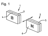
- Fig. 1
- eine schematische Darstellung der Magnetanordnung
- Fig. 1
- a schematic representation of the magnet assembly
Das in der
Der zweite Magnet 2 bildet dabei in der Magnetanordnung den Sensor, dem zumindest ein nebeneinanderliegendes und in Richtung des Sensors weisendes Polpaar 3, 4 des ersten Magneten 1 gegenüberliegt.In this case, the
Der zweite Magnet 2 kann dabei, ein mechanischer Auslöser sein oder an diesem angebracht sein. Der zweite Magnet 2 soll dabei ein in Richtung der ersten Magnetanordnung weisendes Polpaar besitzen. Da der mechanische Auslöser als Sperrelement einer Verriegelungseinrichtung, zumindest gewisse Reibungskräfte überwinden muss und gegebenenfalls auch unter Einfluss eines Kraftspeichers steht, der in Richtung einer Verriegelungsstellung wirksam ist, sind die durch die Anordnung erhöhten Kräfte vorteilhaft. Um die räumliche Nähe der ersten und zweiten Magneten 1, 2 sicherzustellen, kann der erste oder zweite Magnet 1, 2 an einem Tastarm entsprechend der
Gleichwohl ist durch die Fokussierung des Magnetfeldes des ersten oder zweiten Magneten bei der Anordnung auch ein Reedkontakt vorteilhaft, der mit einem der genannten Magneten 1, 2 zusammenwirkt.Nevertheless, by focusing the magnetic field of the first or second magnet in the arrangement, a reed contact which cooperates with one of the mentioned
- 11
- Magnetmagnet
- 22
- Magnetmagnet
- 33
- Polpole
- 44
- Polpole
- 55
- Polpole
- 66
- Polpole
- 77
- Bewegungsrichtungmovement direction
Claims (5)
dadurch gekennzeichnet,
dass der Magnet (1, 2) zumindest ein nebeneinanderliegendes und in Richtung des Sensors weisendes Polpaar (3, 4 oder 5, 6) eines Permanentmagneten aufweist.Magnetic arrangement for interacting with a mechanical and / or electromechanical sensor which changes its state in a defined manner when approaching a magnet (1, 2),
characterized,
that the magnet (1, 2) has at least one lying next to one another and pointing in the direction of the sensor pair of poles (3, 4, or 5, 6) of a permanent magnet.
dadurch gekennzeichnet,
dass der Sensor ein mechanischer Auslöser oder teil desselben ist, der seinerseits einen zweiten Magneten (2) mit einem in Richtung der ersten Magneten (1) weisenden Polpaar (5, 6) besitzt.Magnet arrangement according to claim 1,
characterized,
that the sensor is a mechanical shutter or part thereof is, in turn, a second magnet (2) with a in the direction of the first magnet (1) facing the pole pair (5, 6) has.
dadurch gekennzeichnet,
dass der mechanische Auslöser das Sperrelement einer Verriegelungseinrichtung ist, die unter Einfluss eines Kraftspeichers steht, der in Richtung einer Verriegelungsstellung wirksam ist.Magnet arrangement according to claim 2,
characterized,
that the mechanical release is the locking element of a locking device, which is under the influence of an energy storage device, which is effective in the direction of a locking position.
dadurch gekennzeichnet,
dass der erste Magnet (1) an einem beweglichen Tastarm angebracht ist.Magnet arrangement according to claim 2 and 3,
characterized,
that the first magnet (1) is mounted on a movable sensor arm.
dadurch gekennzeichnet,
dass der Sensor ein Reedkontakt ist.Magnet arrangement according to claim 1,
characterized,
that the sensor is a reed contact.
Applications Claiming Priority (1)
| Application Number | Priority Date | Filing Date | Title |
|---|---|---|---|
| DE202014009713.5U DE202014009713U1 (en) | 2014-12-10 | 2014-12-10 | magnet assembly |
Publications (1)
| Publication Number | Publication Date |
|---|---|
| EP3032005A1 true EP3032005A1 (en) | 2016-06-15 |
Family
ID=52478915
Family Applications (1)
| Application Number | Title | Priority Date | Filing Date |
|---|---|---|---|
| EP15193176.3A Withdrawn EP3032005A1 (en) | 2014-12-10 | 2015-11-05 | Magnet assembly |
Country Status (2)
| Country | Link |
|---|---|
| EP (1) | EP3032005A1 (en) |
| DE (1) | DE202014009713U1 (en) |
Families Citing this family (1)
| Publication number | Priority date | Publication date | Assignee | Title |
|---|---|---|---|---|
| EP3914792B1 (en) | 2019-03-26 | 2022-06-29 | Alban Giacomo S.p.A. | Automatic system for closing windows or doors |
Citations (10)
| Publication number | Priority date | Publication date | Assignee | Title |
|---|---|---|---|---|
| US4966041A (en) * | 1987-12-08 | 1990-10-30 | Nippon Seiko Kabushiki Kaisha | Displacement detection device |
| EP0537805A2 (en) | 1989-05-12 | 1993-04-21 | Aug. Winkhaus GmbH & Co. KG | Window system for a building |
| DE4329960A1 (en) | 1993-09-04 | 1995-03-09 | Windhorst Beteiligungsgesellsc | Permanent magnet arrangement for producing a defined variable magnetic field |
| DE29519486U1 (en) | 1994-12-16 | 1996-02-08 | Poniatowski Siegfried | Device for monitoring the window closure state of an opening cover element and opening cover element with such a closure state monitoring |
| DE19518527A1 (en) | 1995-05-19 | 1996-11-21 | Winkhaus Fa August | Monitorable locking arrangement for a window or a door or the like |
| DE29914387U1 (en) | 1999-08-17 | 1999-12-30 | Rein Hans Helmut | Device for bundling field lines of a primary magnetic field to form a secondary magnetic field of increased field line density with spiral-shaped field lines |
| EP2096241A2 (en) | 2008-02-28 | 2009-09-02 | Carl Fuhr GmbH & Co. KG | Self-sealing additional lock |
| EP2314810A2 (en) | 2009-10-26 | 2011-04-27 | KFV Karl Fliether GmbH & Co. KG | Blocking device for an espagnolette rod |
| WO2013067091A1 (en) * | 2011-11-03 | 2013-05-10 | Sargent Manufacturing Company | Door lock with integrated door position sensor |
| WO2014170124A1 (en) * | 2013-04-19 | 2014-10-23 | Trw Automotive Electronics & Components Gmbh | Proximity sensor of an assembly |
-
2014
- 2014-12-10 DE DE202014009713.5U patent/DE202014009713U1/en not_active Expired - Lifetime
-
2015
- 2015-11-05 EP EP15193176.3A patent/EP3032005A1/en not_active Withdrawn
Patent Citations (11)
| Publication number | Priority date | Publication date | Assignee | Title |
|---|---|---|---|---|
| US4966041A (en) * | 1987-12-08 | 1990-10-30 | Nippon Seiko Kabushiki Kaisha | Displacement detection device |
| EP0537805A2 (en) | 1989-05-12 | 1993-04-21 | Aug. Winkhaus GmbH & Co. KG | Window system for a building |
| EP0599809A2 (en) | 1989-05-12 | 1994-06-01 | Aug. Winkhaus GmbH & Co. KG | Window system for a building |
| DE4329960A1 (en) | 1993-09-04 | 1995-03-09 | Windhorst Beteiligungsgesellsc | Permanent magnet arrangement for producing a defined variable magnetic field |
| DE29519486U1 (en) | 1994-12-16 | 1996-02-08 | Poniatowski Siegfried | Device for monitoring the window closure state of an opening cover element and opening cover element with such a closure state monitoring |
| DE19518527A1 (en) | 1995-05-19 | 1996-11-21 | Winkhaus Fa August | Monitorable locking arrangement for a window or a door or the like |
| DE29914387U1 (en) | 1999-08-17 | 1999-12-30 | Rein Hans Helmut | Device for bundling field lines of a primary magnetic field to form a secondary magnetic field of increased field line density with spiral-shaped field lines |
| EP2096241A2 (en) | 2008-02-28 | 2009-09-02 | Carl Fuhr GmbH & Co. KG | Self-sealing additional lock |
| EP2314810A2 (en) | 2009-10-26 | 2011-04-27 | KFV Karl Fliether GmbH & Co. KG | Blocking device for an espagnolette rod |
| WO2013067091A1 (en) * | 2011-11-03 | 2013-05-10 | Sargent Manufacturing Company | Door lock with integrated door position sensor |
| WO2014170124A1 (en) * | 2013-04-19 | 2014-10-23 | Trw Automotive Electronics & Components Gmbh | Proximity sensor of an assembly |
Also Published As
| Publication number | Publication date |
|---|---|
| DE202014009713U1 (en) | 2015-01-30 |
Similar Documents
| Publication | Publication Date | Title |
|---|---|---|
| DE4341810B4 (en) | Sensor device for position detection of a piston | |
| EP3266963B1 (en) | Locking system | |
| DE202007018456U1 (en) | Magnetic switching device | |
| EP2284340A2 (en) | Magnetic catch for closure of an opening | |
| DE1233714B (en) | Photographic camera shutter with an electro-magnetically operated shutter blade system | |
| DE102013104001B3 (en) | Proximity sensor and module | |
| DE2844538B1 (en) | Dispensing and registration device for food and beverages in the catering trade | |
| EP3032005A1 (en) | Magnet assembly | |
| EP2787110A1 (en) | Door lock for electric household appliances | |
| DE3225499C2 (en) | Magnetic proximity sensor | |
| EP3908728A1 (en) | Motor vehicle lock | |
| DE1553544A1 (en) | Lock with magnetically controllable locking device | |
| DE2041789B2 (en) | ACTUATING DEVICE FOR PRESSURE HAMMER | |
| DE4311496A1 (en) | Manual angle encoder | |
| DE102016205831A1 (en) | Actuating device and method for operating an actuator | |
| DE102011107472A1 (en) | Door opening device with permanent magnet | |
| DE1963596C3 (en) | Electrical pulse generator with protective tube contact | |
| DE19960891C2 (en) | Encoder or linear encoder in particular for the detection of slow movements and directions of movement | |
| DE102017108674A1 (en) | Closure device for a door of a household appliance, such as a laundry treatment machine with a treatment room arranged in a housing | |
| DE102007000597A1 (en) | Method and device for contactless measurement of a relative displacement of components to each other | |
| DE3406410C2 (en) | ||
| EP1867956B1 (en) | Enlargement of the effective range of magnetic sensors using a support field | |
| DE102008033508A1 (en) | Sprinkler and switching device for a sprinkler | |
| DE1291406B (en) | Device for actuating electrical contacts | |
| EP1746371A2 (en) | Door opening aid for apparatuses, preferably cooling or freezing apparatuses |
Legal Events
| Date | Code | Title | Description |
|---|---|---|---|
| PUAI | Public reference made under article 153(3) epc to a published international application that has entered the european phase |
Free format text: ORIGINAL CODE: 0009012 |
|
| AK | Designated contracting states |
Kind code of ref document: A1 Designated state(s): AL AT BE BG CH CY CZ DE DK EE ES FI FR GB GR HR HU IE IS IT LI LT LU LV MC MK MT NL NO PL PT RO RS SE SI SK SM TR |
|
| AX | Request for extension of the european patent |
Extension state: BA ME |
|
| STAA | Information on the status of an ep patent application or granted ep patent |
Free format text: STATUS: THE APPLICATION IS DEEMED TO BE WITHDRAWN |
|
| 18D | Application deemed to be withdrawn |
Effective date: 20161215 |