EP3031888A1 - Method for manufacturing grease - Google Patents
Method for manufacturing grease Download PDFInfo
- Publication number
- EP3031888A1 EP3031888A1 EP14835283.4A EP14835283A EP3031888A1 EP 3031888 A1 EP3031888 A1 EP 3031888A1 EP 14835283 A EP14835283 A EP 14835283A EP 3031888 A1 EP3031888 A1 EP 3031888A1
- Authority
- EP
- European Patent Office
- Prior art keywords
- grease
- manufacturing
- base oil
- thickener
- shear rate
- Prior art date
- Legal status (The legal status is an assumption and is not a legal conclusion. Google has not performed a legal analysis and makes no representation as to the accuracy of the status listed.)
- Granted
Links
Images





Classifications
-
- C—CHEMISTRY; METALLURGY
- C10—PETROLEUM, GAS OR COKE INDUSTRIES; TECHNICAL GASES CONTAINING CARBON MONOXIDE; FUELS; LUBRICANTS; PEAT
- C10M—LUBRICATING COMPOSITIONS; USE OF CHEMICAL SUBSTANCES EITHER ALONE OR AS LUBRICATING INGREDIENTS IN A LUBRICATING COMPOSITION
- C10M169/00—Lubricating compositions characterised by containing as components a mixture of at least two types of ingredient selected from base-materials, thickeners or additives, covered by the preceding groups, each of these compounds being essential
- C10M169/02—Mixtures of base-materials and thickeners
-
- B—PERFORMING OPERATIONS; TRANSPORTING
- B01—PHYSICAL OR CHEMICAL PROCESSES OR APPARATUS IN GENERAL
- B01F—MIXING, e.g. DISSOLVING, EMULSIFYING OR DISPERSING
- B01F27/00—Mixers with rotary stirring devices in fixed receptacles; Kneaders
- B01F27/27—Mixers with stator-rotor systems, e.g. with intermeshing teeth or cylinders or having orifices
- B01F27/272—Mixers with stator-rotor systems, e.g. with intermeshing teeth or cylinders or having orifices with means for moving the materials to be mixed axially between the surfaces of the rotor and the stator, e.g. the stator rotor system formed by conical or cylindrical surfaces
- B01F27/2722—Mixers with stator-rotor systems, e.g. with intermeshing teeth or cylinders or having orifices with means for moving the materials to be mixed axially between the surfaces of the rotor and the stator, e.g. the stator rotor system formed by conical or cylindrical surfaces provided with ribs, ridges or grooves on one surface
-
- B—PERFORMING OPERATIONS; TRANSPORTING
- B01—PHYSICAL OR CHEMICAL PROCESSES OR APPARATUS IN GENERAL
- B01J—CHEMICAL OR PHYSICAL PROCESSES, e.g. CATALYSIS OR COLLOID CHEMISTRY; THEIR RELEVANT APPARATUS
- B01J19/00—Chemical, physical or physico-chemical processes in general; Their relevant apparatus
- B01J19/18—Stationary reactors having moving elements inside
- B01J19/1806—Stationary reactors having moving elements inside resulting in a turbulent flow of the reactants, such as in centrifugal-type reactors, or having a high Reynolds-number
-
- C—CHEMISTRY; METALLURGY
- C10—PETROLEUM, GAS OR COKE INDUSTRIES; TECHNICAL GASES CONTAINING CARBON MONOXIDE; FUELS; LUBRICANTS; PEAT
- C10M—LUBRICATING COMPOSITIONS; USE OF CHEMICAL SUBSTANCES EITHER ALONE OR AS LUBRICATING INGREDIENTS IN A LUBRICATING COMPOSITION
- C10M105/00—Lubricating compositions characterised by the base-material being a non-macromolecular organic compound
- C10M105/02—Well-defined hydrocarbons
- C10M105/04—Well-defined hydrocarbons aliphatic
-
- C—CHEMISTRY; METALLURGY
- C10—PETROLEUM, GAS OR COKE INDUSTRIES; TECHNICAL GASES CONTAINING CARBON MONOXIDE; FUELS; LUBRICANTS; PEAT
- C10M—LUBRICATING COMPOSITIONS; USE OF CHEMICAL SUBSTANCES EITHER ALONE OR AS LUBRICATING INGREDIENTS IN A LUBRICATING COMPOSITION
- C10M115/00—Lubricating compositions characterised by the thickener being a non-macromolecular organic compound other than a carboxylic acid or salt thereof
- C10M115/08—Lubricating compositions characterised by the thickener being a non-macromolecular organic compound other than a carboxylic acid or salt thereof containing nitrogen
-
- B—PERFORMING OPERATIONS; TRANSPORTING
- B01—PHYSICAL OR CHEMICAL PROCESSES OR APPARATUS IN GENERAL
- B01J—CHEMICAL OR PHYSICAL PROCESSES, e.g. CATALYSIS OR COLLOID CHEMISTRY; THEIR RELEVANT APPARATUS
- B01J2219/00—Chemical, physical or physico-chemical processes in general; Their relevant apparatus
- B01J2219/00761—Details of the reactor
- B01J2219/00763—Baffles
- B01J2219/00779—Baffles attached to the stirring means
-
- C—CHEMISTRY; METALLURGY
- C10—PETROLEUM, GAS OR COKE INDUSTRIES; TECHNICAL GASES CONTAINING CARBON MONOXIDE; FUELS; LUBRICANTS; PEAT
- C10M—LUBRICATING COMPOSITIONS; USE OF CHEMICAL SUBSTANCES EITHER ALONE OR AS LUBRICATING INGREDIENTS IN A LUBRICATING COMPOSITION
- C10M2205/00—Organic macromolecular hydrocarbon compounds or fractions, whether or not modified by oxidation as ingredients in lubricant compositions
- C10M2205/02—Organic macromolecular hydrocarbon compounds or fractions, whether or not modified by oxidation as ingredients in lubricant compositions containing acyclic monomers
- C10M2205/028—Organic macromolecular hydrocarbon compounds or fractions, whether or not modified by oxidation as ingredients in lubricant compositions containing acyclic monomers containing aliphatic monomers having more than four carbon atoms
- C10M2205/0285—Organic macromolecular hydrocarbon compounds or fractions, whether or not modified by oxidation as ingredients in lubricant compositions containing acyclic monomers containing aliphatic monomers having more than four carbon atoms used as base material
-
- C—CHEMISTRY; METALLURGY
- C10—PETROLEUM, GAS OR COKE INDUSTRIES; TECHNICAL GASES CONTAINING CARBON MONOXIDE; FUELS; LUBRICANTS; PEAT
- C10M—LUBRICATING COMPOSITIONS; USE OF CHEMICAL SUBSTANCES EITHER ALONE OR AS LUBRICATING INGREDIENTS IN A LUBRICATING COMPOSITION
- C10M2215/00—Organic non-macromolecular compounds containing nitrogen as ingredients in lubricant Compositions
- C10M2215/10—Amides of carbonic or haloformic acids
- C10M2215/102—Ureas; Semicarbazides; Allophanates
- C10M2215/1026—Ureas; Semicarbazides; Allophanates used as thickening material
-
- C—CHEMISTRY; METALLURGY
- C10—PETROLEUM, GAS OR COKE INDUSTRIES; TECHNICAL GASES CONTAINING CARBON MONOXIDE; FUELS; LUBRICANTS; PEAT
- C10M—LUBRICATING COMPOSITIONS; USE OF CHEMICAL SUBSTANCES EITHER ALONE OR AS LUBRICATING INGREDIENTS IN A LUBRICATING COMPOSITION
- C10M2217/00—Organic macromolecular compounds containing nitrogen as ingredients in lubricant compositions
- C10M2217/04—Macromolecular compounds from nitrogen-containing monomers obtained otherwise than by reactions only involving carbon-to-carbon unsaturated bonds
- C10M2217/045—Polyureas; Polyurethanes
- C10M2217/0456—Polyureas; Polyurethanes used as thickening agents
-
- C—CHEMISTRY; METALLURGY
- C10—PETROLEUM, GAS OR COKE INDUSTRIES; TECHNICAL GASES CONTAINING CARBON MONOXIDE; FUELS; LUBRICANTS; PEAT
- C10N—INDEXING SCHEME ASSOCIATED WITH SUBCLASS C10M RELATING TO LUBRICATING COMPOSITIONS
- C10N2030/00—Specified physical or chemical properties which is improved by the additive characterising the lubricating composition, e.g. multifunctional additives
- C10N2030/76—Reduction of noise, shudder, or vibrations
-
- C—CHEMISTRY; METALLURGY
- C10—PETROLEUM, GAS OR COKE INDUSTRIES; TECHNICAL GASES CONTAINING CARBON MONOXIDE; FUELS; LUBRICANTS; PEAT
- C10N—INDEXING SCHEME ASSOCIATED WITH SUBCLASS C10M RELATING TO LUBRICATING COMPOSITIONS
- C10N2040/00—Specified use or application for which the lubricating composition is intended
- C10N2040/02—Bearings
-
- C—CHEMISTRY; METALLURGY
- C10—PETROLEUM, GAS OR COKE INDUSTRIES; TECHNICAL GASES CONTAINING CARBON MONOXIDE; FUELS; LUBRICANTS; PEAT
- C10N—INDEXING SCHEME ASSOCIATED WITH SUBCLASS C10M RELATING TO LUBRICATING COMPOSITIONS
- C10N2050/00—Form in which the lubricant is applied to the material being lubricated
- C10N2050/10—Form in which the lubricant is applied to the material being lubricated semi-solid; greasy
-
- C—CHEMISTRY; METALLURGY
- C10—PETROLEUM, GAS OR COKE INDUSTRIES; TECHNICAL GASES CONTAINING CARBON MONOXIDE; FUELS; LUBRICANTS; PEAT
- C10N—INDEXING SCHEME ASSOCIATED WITH SUBCLASS C10M RELATING TO LUBRICATING COMPOSITIONS
- C10N2070/00—Specific manufacturing methods for lubricant compositions
Definitions
- the present invention relates to a grease manufacturing method.
- a typical manufacturing method of a urea grease includes: mixing a base oil with isocyanate to prepare a first solution kept at about 60 degrees C; mixing a base oil with amine to prepare a second solution kept at about 60 degrees C; adding the second solution to the first solution with stirring; heating the obtained mixture to about 160 degrees C; and subsequently cooling the mixture to the room temperature.
- this method takes time for manufacturing (i.e., synthetic reaction) and is likely to generate micelle particles (so-called lumps) formed of a thickener. Large lumps are known for deteriorating an acoustic property when the grease is used in a slide device such as a bearing.
- the thickener having a non-uniform structure formed of large lumps less contributes to an inherent performance of the grease, an efficiency of the thickener is decreased. In other words, a lot of thickener is required for obtaining a predetermined hardness.
- Patent Literature 1 a grease manufacturing method for inhibiting formation of large lumps and improving an acoustic property has been proposed (see Patent Literatures 1 and 2).
- the manufacturing method disclosed in Patent Literature 1 includes: a method of feeding an amine solution (or an isocyanate solution) with liquid drops having a diameter of 300 ⁇ m or less into an isocyanate solution (or an amine solution) using a spray nozzle; and a method of spraying the above solutions to each other for reaction.
- This manufacturing method restricts a particle diameter of each of lumps formed of the thickener (a urea compound) to less than 100 ⁇ m (about several tens ⁇ m).
- Patent Literature 2 includes a method of applying pressure to an amine solution and an isocyanate solution using a pressure device to increase the pressure to a predetermined pressure, and mixing the solutions by colliding with each other for reaction. This manufacturing method restricts a size of each of lumps to a range from about several hundreds ⁇ m to several tens ⁇ m.
- Patent Literatures 1 and 2 raise concern about environment pollution and harmful effects caused by scattered amine and isocyanate and moreover are not necessarily sufficient for downsizing the lumps to fine particles.
- An object of the invention is to provide a grease manufacturing method inhibiting generation of large micelle particles (large lumps) formed of a thickener.
- the invention provides the following grease manufacturing method.
- the grease manufacturing method inhibiting generation of large micelle particles (large lumps) formed of the thickener can be provided.
- a first base oil containing a first thickener precursor and a second base oil containing a second thickener precursor are mixed to prepare a mixture and a shear rate of 10 2 s -1 or more is applied to the mixture.
- a shear rate of 10 2 s -1 or more is applied to the mixture.
- high-rate shearing is applied to the mixture.
- the first thickener precursor and the second thickener precursor are mixed and dispersed to react with each other, thereby preparing a thickener.
- the first base oil and the second base oil used in the present manufacturing method are not particularly limited, but any mineral base oil and synthetic base oil used for typically manufacturing a grease are usable.
- the mineral base oil and synthetic base oil may be used singularly or in combination.
- Usable mineral oils are obtained by purification in an appropriate combination of vacuum distillation, solvent deasphalting, solvent extraction, hydrocracking, solvent dewaxing, sulfate cleaning, clay purification, hydrorefining and the like.
- the synthetic base oil include polyalphaolefin (PAO) base oil, other hydrocarbon base oil, ester base oil, alkyldiphenylether base oil, polyalkylene glycol base oil (PAG), and alkylbenzene base oil.
- a kinematic viscosity at 40 degrees C of each of the first base oil and the second base oil is preferably in a range from 10 mm 2 /s to 600 mm 2 /s.
- the first base oil and the second base oil preferably have similar polar characteristics and similar viscosity characteristics. Accordingly, the first base oil and the second base oil are most preferably the same base oil in use.
- a thickener is manufactured (synthesized) from two types of thickener precursors.
- the thickener precursors are not particularly limited. When the thickener is urea, the thickener precursors are monoamine and isocyanate (diisocyanate).
- monoamine examples include: an aromatic monoamine such as aniline, p-toluidine, and naphthyl amine; an aliphatic monoamine such as hexyl amine, cyclohexyl amine, octyl amine, dodecyl amine, hexadecyl amine, and eicosyl amine.
- aromatic monoamine such as aniline, p-toluidine, and naphthyl amine
- an aliphatic monoamine such as hexyl amine, cyclohexyl amine, octyl amine, dodecyl amine, hexadecyl amine, and eicosyl amine.
- a polyurea compound is obtainable by reacting, for instance, diisocyanate with monoamine or diamine.
- diisocyanate and monoamine used for forming the polyurea compound are the same as examples of diisocyanate and monoamine used for forming a diurea compound.
- diamine include ethylenediamine, propanediamine, butanediamine, hexandiamine, octanediamine, phenylenediamine, tolylenediamine, xylenediamine, and diaminodiphenylmethane.
- isocyanate examples include diphenylmethane-4,4'-diisocyanate (MDI), tolylenediisocyanate, and naphthylene-1,5-diisocyanate.
- MDI diphenylmethane-4,4'-diisocyanate
- isocyanates may be used alone or a plurality of isocyanates may be mixed in use.
- the above isocyanate and monoamine are continuously introduced at a molar ratio of 1:2 into a reactor (a grease manufacturing device) and are immediately subjected to high shearing as described later to be mixed and reacted with each other, so that a diurea grease having less large lumps can be manufactured.
- the above isocyanate and a mixture of monoamine and diamine are continuously introduced at equivalent amounts of an isocyanate group and an amino group into a reactor (a grease manufacturing device) and are similarly subjected to high shearing as described later to be mixed and reacted with each other, so that a polyurea grease having less large lumps can be manufactured.
- the first base oil containing the first thickener precursor and the second base oil containing the second thickener precursor are mixed to prepare a mixture and a shear rate of 10 2 s -1 or more is applied to the mixture.
- a shear rate of 10 2 s -1 or more is applied to the mixture.
- a time elapsed before applying the above shear rate after mixing the first base oil and the second base oil is preferably within 15 minutes, more preferably within 5 minutes, further preferably within 10 seconds. Since a reaction starts after the precursors 1 and 2 are well mixed and dispersed, when the elapsed time is shorter, molecules of the thickener are less likely to form a thick bundle and a large lump.
- the shear rate applied to the above mixture is 10 2 s -1 or more as described above, preferably 10 3 s -1 or more, more preferably 10 4 s -1 or more.
- a higher shear rate provides a more improved dispersion condition of the thickener precursors 1 and 2 and the generated thickener, thereby providing a more uniformed grease structure.
- the molecules of the thickener do not form a thick bundle and a large lump.
- the shear rate applied to the above mixture is preferably 10 7 s -1 or less.
- the above shear rate can be applied to the mixture, for instance, by introducing the mixture into a reactor configured to cause shearing by relative movement of facing wall surfaces. It should be noted that the shear rate represents the same as a later-described maximum shear rate.
- a grease manufacturing device (the reactor) capable of generating such a high shear rate is exemplified by a manufacturing device structured as shown in Fig. 1 .
- Fig. 2 schematically shows a lateral side and a top of the manufacturing device in Fig. 1 .
- the manufacturing device shown in Fig. 1 is configured to mix two types of base oils and uniformly apply high-rate shearing to the obtained mixture within an extremely short time.
- the high-rate shearing is applied to the mixture by a gap (a, b) between a high-speed rotating portion and an inner wall of the reactor.
- the gap may be adjusted by changing the diameter of the high-speed rotating portion in the direction of the rotary shaft, or alternatively, by providing the high-speed rotating portion in a form of a truncated cone and vertically moving the high-speed rotating portion with respect to an inner wall of a tapered reactor.
- the portions having a large gap may be provided by a screw or a spiral having continuous inclination, whereby extrusion capability may be provided to the high-speed rotating portion.
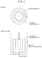
- Fig. 3 shows a reactor (a manufacturing device of a grease) having a structure different from that of the reactor in Fig. 1 , the portions having different gaps are disposed in a rotation direction.
- the portions having a large gap may be inclined relative to a rotary shaft, whereby extrusion capability as provided by a screw may be provided to the high-speed rotating portion.
- a ratio (Max/Min) of a maximum shear rate (Max) to a minimum shear rate (Min) is preferably 100 or less, more preferably 50 or less, further preferably 10 or less.
- the maximum shear rate (Max) refers to a maximum shear rate applied to the mixture and the minimum shear rate (Min) refers to a minimum shear rate applied to the mixture.
- the maximum shear rate (Max) and the minimum shear rate (Min) are defined as follows, for instance, in the reactor shown in Fig 1 .
- Max (a linear rate of a surface of the high-speed rotating portion at the minimum gap between the surface of the high-speed rotating portion and an inner wall surface of the reactor/the gap)
- Min (a linear rate of a surface of the high-speed rotating portion at the maximum gap between the surface of the high-speed rotating portion and the inner wall surface of the reactor/the gap)
- the gap used for calculating Max is a and the gap used for calculating Min is b.
- the high-speed rotating portion is most preferably a cylinder vertically having a uniform diameter.
- the manufacturing device When the manufacturing device manufactures a urea grease, the manufacturing device may have a structure as shown in Fig. 2 .
- the present manufacturing method is applicable to all grease manufacturing methods including mixing a solution of the first base oil and the first thickener precursor with a solution of the second base oil and the second thickener precursor.
- a temperature condition for manufacturing the thickener differs depending on the precursors to be used, the temperature in a range from approximately 50 degrees C to 200 degrees C is preferable when manufacturing urea as the thickener.
- isocyanate is likely to be solved in the base oil.
- the temperature is equal to or less than 200 degrees C, deterioration of the base oil can be sufficiently inhibited.
- a temperature of a solution of the base oil and amine before being introduced into the reactor is preferably in a range from approximately 50 degrees C to 100 degrees C.
- the grease obtained by the above manufacturing method may be further kneaded.
- a roll mill generally used for manufacturing a grease is usable.
- the above grease may be subjected to the roll mill twice or more.
- the grease obtained by the above manufacturing method may be further heated to the temperature in a range from 80 degrees C to 200 degrees C. Further, for uniform heating, the grease may be kneaded and stirred. A furnace and the like may be used for heating.
- additives may be further added to the grease obtained by the present manufacturing method.
- the additive include an antioxidant, extreme pressure agent, rust inhibitor, and a solid lubricant.
- antioxidants examples include: an amine antioxidant such as alkylated diphenylamine, phenyl- ⁇ -naphthylamine and alkylated- ⁇ -naphthylamine; and a phenol antioxidant such as 2,6-di-t-butyl-4-methylphenol and 4.4-methylenebis(2,6-di-t-butylphenol).
- a content of the antioxidant is preferably in a range from approximately 0.05 mass% to 2 mass% based on a total amount of the grease.
- the extreme pressure agent examples include thiocarbamates such as zinc dialkyldithiophosphate, molybdenum dialkyldithiophosphate, ashless dithiocarbamate, zinc dithiocarbamate and molybdenum dithiocarbamate, sulfur compound (sulfurized fat and oil, sulfurized olefin, polysulfide, sulfurized mineral oil, thiophosphates, thioterpenes and dialkylthiodipropionates), phosphates and phosphites (tricresyl phosphate and triphenyl phosphite).
- a content of the extreme pressure agent is preferably in a range from approximately 0.1 mass% to 5 mass% based on the total amount of the grease.
- rust inhibitor examples include benzotriazole, zinc stearate, succinate, succinic acid derivative, thiadiazole, benzotriazole, benzotriazole derivative, sodium nitrite, petroleum sulphonate, sorbitan monooleate, fatty acid soap and amine compound.
- a content of the rust inhibitor is preferably in a range from approximately 0.01 mass% to 10 mass% based on the total amount of the grease.
- solid lubricant examples include polyimide, PTFE, graphite, metal oxide, boron nitride, melamine cyanurate (MCA) and molybdenum disulfide.
- One of the above various additives may be blended alone, or alternatively, a plurality of those may be blended in combination.
- a grease was manufactured using a urea grease manufacturing device as shown in Fig. 3 .
- a grease manufacturing method was specifically performed as follows.
- a PAO base oil (manufactured by INEOS Oligomers: Durasyn170, containing cyclohexylamine of 28.1 mass%) heated at 70 degrees C and a PAO base oil (manufactured by INEOS Oligomers: Durasyn170, containing MDI of 11.0 mass%) heated at 70 degrees C were continuously introduced at respective flow rates of 144 mL/min and 504 mL/min into a manufacturing device. Immediately after the introduction, a maximum shear rate of 42,000s -1 was applied to the obtained mixture by a high-speed rotating portion when the mixture passes a gap.
- a ratio (Max/Min) of the maximum shear rate (Max) to the minimum shear rate (Min) when the mixture passes the gap was 1.03.
- a time elapsed before applying the maximum shear rate to the mixture after mixing the above two base oils was about three seconds.
- An amount of a thickener was 15 mass% in the manufactured grease.
- Example 1 The grease manufactured in Example 1 was kneaded by the roll mill twice.
- a grease was manufactured in the same manner as in Example 1, except that the maximum shear rate applied to the mixture was 83,900s -1 .
- the amount of the thickener was 15 mass% in the manufactured grease.
- Example 3 The grease manufactured in Example 3 was kneaded by the roll mill twice.
- a grease was manufactured in the same manner as in Example 1, except that a concentration of cyclohexylamine was 23.8 mass%, a concentration of MDI was 9.0 mass%, the flow rate of the amine solution was 100 mL/min, the flow rate of the MDI solution was 330 mL/min, and the maximum shear rate was 216,000s -1 .
- the amount of the thickener was 12 mass% in the manufactured grease.
- Example 5 The grease manufactured in Example 5 was kneaded by the roll mill twice.
- a urea grease was manufactured by a typical method. Specifically, as shown in Fig. 4 , a PAO base oil (manufactured by INEOS Oligomers: Durasyn170, containing cyclohexylamine of 15.7mass%) kept at 60 degrees C was dropped into a PAO base oil (manufactured by INEOS Oligomers: Durasyn170, containing MDI of 14.5 mass%) stirred by an impeller and kept at 60 degrees C. After the amine solution was dropped therein, the mixture was heated to 160 degrees C with stirring and maintained for one hour. Subsequently, the mixture was cooled with stirring The amount of the thickener was 15 mass% in the manufactured grease.
- Table 1 shows a time for manufacturing the grease, worked penetration (in accordance with JIS K 22205.3) and condition (i.e., size) of lumps in each of Examples and Comparatives.
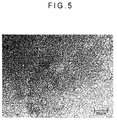
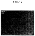
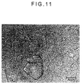
- Figs. 5 to 12 show optical micrographs of the greases.
- the urea grease manufactured in Comparative 1 by a typical method has extremely large lumps and exhibits an extremely poor uniformity.
- the grease of Comparative 1 was kneaded with the roll mill in Comparative 2.
- the lumps generated in Comparative 2 are considerably larger than those in Examples, although being smaller than those in Comparative 1.
- the grease can be manufactured within a time much shorter than a time required in a typical manufacturing method.
- the manufacturing time shown in Table 1 does not include a time required for weighing the base oils, amine and isocyanate (MDI) and heating and solving the base oils, but indicates a time elapsed before finishing manufacturing the grease or finishing the treatment by the roll mill after starting mixing the solutions.
- MDI amine and isocyanate
Landscapes
- Chemical & Material Sciences (AREA)
- Chemical Kinetics & Catalysis (AREA)
- Organic Chemistry (AREA)
- Oil, Petroleum & Natural Gas (AREA)
- General Chemical & Material Sciences (AREA)
- Engineering & Computer Science (AREA)
- Lubricants (AREA)
Abstract
Description
- The present invention relates to a grease manufacturing method.
- A typical manufacturing method of a urea grease includes: mixing a base oil with isocyanate to prepare a first solution kept at about 60 degrees C; mixing a base oil with amine to prepare a second solution kept at about 60 degrees C; adding the second solution to the first solution with stirring; heating the obtained mixture to about 160 degrees C; and subsequently cooling the mixture to the room temperature. However, this method takes time for manufacturing (i.e., synthetic reaction) and is likely to generate micelle particles (so-called lumps) formed of a thickener. Large lumps are known for deteriorating an acoustic property when the grease is used in a slide device such as a bearing. Further, since the thickener having a non-uniform structure formed of large lumps less contributes to an inherent performance of the grease, an efficiency of the thickener is decreased. In other words, a lot of thickener is required for obtaining a predetermined hardness.
- Accordingly, a grease manufacturing method for inhibiting formation of large lumps and improving an acoustic property has been proposed (see
Patent Literatures 1 and 2). The manufacturing method disclosed inPatent Literature 1 includes: a method of feeding an amine solution (or an isocyanate solution) with liquid drops having a diameter of 300 µm or less into an isocyanate solution (or an amine solution) using a spray nozzle; and a method of spraying the above solutions to each other for reaction. This manufacturing method restricts a particle diameter of each of lumps formed of the thickener (a urea compound) to less than 100 µm (about several tens µm). The manufacturing method disclosed inPatent Literature 2 includes a method of applying pressure to an amine solution and an isocyanate solution using a pressure device to increase the pressure to a predetermined pressure, and mixing the solutions by colliding with each other for reaction. This manufacturing method restricts a size of each of lumps to a range from about several hundreds µm to several tens µm. -
- Patent Literature 1:
JP-A-2000-248290 - Patent Literature 2:
JP-A-3-190996 - The manufacturing methods disclosed in
Patent Literatures - An object of the invention is to provide a grease manufacturing method inhibiting generation of large micelle particles (large lumps) formed of a thickener.
- The inventor found that urea molecules and a bundle (fiber structure) were formed within an extremely short time after an isocyanate solution and an amine solution were mixed. The inventor estimated that a non-uniform structure such as a thick bundle and a large lump was formed because a low and/or non-uniform shear rate was applied to the obtained mixture in a typical manufacturing method. The inventor focused attention on this point and found that the lump could be made smaller than that formed in the typical manufacturing method by uniformly applying a high shear to the mixture of above two solutions immediately after being obtained.
- Specifically, the invention provides the following grease manufacturing method.
-
- (1) According to an aspect of the invention, a grease manufacturing method includes: mixing a first base oil containing a first thickener precursor and a second base oil containing a second thickener precursor to prepare a mixture; applying a shear rate of 102s-1 or more to the mixture; and mixing and dispersing the first thickener precursor and the second thickener precursor for reaction to prepare a thickener.
- (2) In the above arrangement, the shear rate is 107s-1 or less.
- (3) In the above arrangement, the shear rate is applied to the mixture within 15 minutes after mixing the first base oil and the second base oil.
- (4) In the above arrangement, a ratio (Max/Min) of a maximum shear rate (Max) to a minimum shear rate (Min) in the shear rate applied to the mixture is 100 or less.
- (5) In the above arrangement, the first thickener precursor is monoamine and the second thickener precursor is diisocyanate.
- (6) In the above arrangement, the shear rate is applied to the mixture by introducing the mixture into a reactor configured to generate shearing by relative movement of facing wall surfaces.
- (7) The grease manufacturing method in the above arrangement further includes: kneading the grease.
- (8) The grease manufacturing method in the above arrangement further includes: heating the grease to a temperature in a range from 80 degrees C to 200 degrees C.
- (9) The grease manufacturing method in the above arrangement further includes: kneading the grease.
- According to the invention, the grease manufacturing method inhibiting generation of large micelle particles (large lumps) formed of the thickener can be provided.
-
-
Fig. 1 is a schematic cross-sectional view showing an example of a manufacturing method (manufacturing device) of a urea grease in an exemplary embodiment of the invention. -
Fig. 2 schematically shows a lateral side and a top of the manufacturing device inFig. 1 . -
Fig. 3 schematically shows a lateral side and a top of a manufacturing device of a urea grease in another exemplary embodiment of the invention. -
Fig. 4 schematically shows a typical manufacturing method of the urea grease. -
Fig. 5 is an optical micrograph of a grease manufactured in Example 1 of the invention. -
Fig. 6 is an optical micrograph of a grease manufactured in Example 2 of the invention. -
Fig. 7 is an optical micrograph of grease manufactured in Example 3 of the invention. -
Fig. 8 is an optical micrograph of a grease manufactured in Example 4 of the invention. -
Fig. 9 is an optical micrograph of a grease manufactured in Example 5 of the invention. -
Fig. 10 is an optical micrograph of a grease manufactured in Example 6 of the invention. -
Fig. 11 is an optical micrograph of a grease manufactured in Comparative 1 of the invention. -
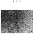
Fig. 12 is an optical micrograph of a grease manufactured in Comparative 2 of the invention. - In a grease manufacturing method according to an exemplary embodiment of the invention (hereinafter also referred to as "the present manufacturing method"), a first base oil containing a first thickener precursor and a second base oil containing a second thickener precursor are mixed to prepare a mixture and a shear rate of 102s-1 or more is applied to the mixture. In other words, within a short time after the first base oil and the second base oil are mixed, high-rate shearing is applied to the mixture. Subsequently, the first thickener precursor and the second thickener precursor are mixed and dispersed to react with each other, thereby preparing a thickener. The exemplary embodiment of the invention will be described below in detail.
- The first base oil and the second base oil used in the present manufacturing method are not particularly limited, but any mineral base oil and synthetic base oil used for typically manufacturing a grease are usable. The mineral base oil and synthetic base oil may be used singularly or in combination.
- Usable mineral oils are obtained by purification in an appropriate combination of vacuum distillation, solvent deasphalting, solvent extraction, hydrocracking, solvent dewaxing, sulfate cleaning, clay purification, hydrorefining and the like. Examples of the synthetic base oil include polyalphaolefin (PAO) base oil, other hydrocarbon base oil, ester base oil, alkyldiphenylether base oil, polyalkylene glycol base oil (PAG), and alkylbenzene base oil. A kinematic viscosity at 40 degrees C of each of the first base oil and the second base oil is preferably in a range from 10 mm2/s to 600 mm2/s.
- Considering compatibility of the first base oil and the second base oil, the first base oil and the second base oil preferably have similar polar characteristics and similar viscosity characteristics. Accordingly, the first base oil and the second base oil are most preferably the same base oil in use.
- In the exemplary embodiment, a thickener is manufactured (synthesized) from two types of thickener precursors. The thickener precursors are not particularly limited. When the thickener is urea, the thickener precursors are monoamine and isocyanate (diisocyanate).
- Examples of monoamine include: an aromatic monoamine such as aniline, p-toluidine, and naphthyl amine; an aliphatic monoamine such as hexyl amine, cyclohexyl amine, octyl amine, dodecyl amine, hexadecyl amine, and eicosyl amine.
- A polyurea compound is obtainable by reacting, for instance, diisocyanate with monoamine or diamine. Examples of diisocyanate and monoamine used for forming the polyurea compound are the same as examples of diisocyanate and monoamine used for forming a diurea compound. Examples of diamine include ethylenediamine, propanediamine, butanediamine, hexandiamine, octanediamine, phenylenediamine, tolylenediamine, xylenediamine, and diaminodiphenylmethane.
- Examples of isocyanate include diphenylmethane-4,4'-diisocyanate (MDI), tolylenediisocyanate, and naphthylene-1,5-diisocyanate. One of the above amines may be used alone or a plurality of amines may be mixed in use. Similarly, one of the above isocyanates may be used alone or a plurality of isocyanates may be mixed in use.
- The above isocyanate and monoamine are continuously introduced at a molar ratio of 1:2 into a reactor (a grease manufacturing device) and are immediately subjected to high shearing as described later to be mixed and reacted with each other, so that a diurea grease having less large lumps can be manufactured. Moreover, the above isocyanate and a mixture of monoamine and diamine are continuously introduced at equivalent amounts of an isocyanate group and an amino group into a reactor (a grease manufacturing device) and are similarly subjected to high shearing as described later to be mixed and reacted with each other, so that a polyurea grease having less large lumps can be manufactured.
- In the present manufacturing method, the first base oil containing the first thickener precursor and the second base oil containing the second thickener precursor are mixed to prepare a mixture and a shear rate of 102s-1 or more is applied to the mixture. In other words, in order to inhibit formation or growth of the lumps, it is crucial to apply high-rate shearing to the mixture within the shortest time as possible after the first base oil and the second base oil are mixed.
- Specifically, a time elapsed before applying the above shear rate after mixing the first base oil and the second base oil is preferably within 15 minutes, more preferably within 5 minutes, further preferably within 10 seconds. Since a reaction starts after the
precursors - The shear rate applied to the above mixture is 102s-1 or more as described above, preferably 103s-1 or more, more preferably 104s-1 or more. A higher shear rate provides a more improved dispersion condition of the
thickener precursors - Considering safety of the device and heat generated by shearing and the like and removal of the heat, the shear rate applied to the above mixture is preferably 107s-1 or less.
- The above shear rate can be applied to the mixture, for instance, by introducing the mixture into a reactor configured to cause shearing by relative movement of facing wall surfaces. It should be noted that the shear rate represents the same as a later-described maximum shear rate.
- A grease manufacturing device (the reactor) capable of generating such a high shear rate is exemplified by a manufacturing device structured as shown in
Fig. 1 .Fig. 2 schematically shows a lateral side and a top of the manufacturing device inFig. 1 . - The manufacturing device shown in
Fig. 1 is configured to mix two types of base oils and uniformly apply high-rate shearing to the obtained mixture within an extremely short time. The high-rate shearing is applied to the mixture by a gap (a, b) between a high-speed rotating portion and an inner wall of the reactor. A diameter of the high-speed rotating portion may be constant (a=b) in a direction of a rotary shaft, or alternatively, the gap may be different. The gap may be adjusted by changing the diameter of the high-speed rotating portion in the direction of the rotary shaft, or alternatively, by providing the high-speed rotating portion in a form of a truncated cone and vertically moving the high-speed rotating portion with respect to an inner wall of a tapered reactor. - Further, the portions having a large gap may be provided by a screw or a spiral having continuous inclination, whereby extrusion capability may be provided to the high-speed rotating portion.
-
Fig. 3 shows a reactor (a manufacturing device of a grease) having a structure different from that of the reactor inFig. 1 , the portions having different gaps are disposed in a rotation direction. In this manufacturing device, the portions having a large gap may be inclined relative to a rotary shaft, whereby extrusion capability as provided by a screw may be provided to the high-speed rotating portion. - In the above reactor, a ratio (Max/Min) of a maximum shear rate (Max) to a minimum shear rate (Min) is preferably 100 or less, more preferably 50 or less, further preferably 10 or less. When the shear rate applied to the mixture is as uniform as possible, a grease having a uniform structure without having grown lumps is provided.
- Herein, the maximum shear rate (Max) refers to a maximum shear rate applied to the mixture and the minimum shear rate (Min) refers to a minimum shear rate applied to the mixture. The maximum shear rate (Max) and the minimum shear rate (Min) are defined as follows, for instance, in the reactor shown in
Fig 1 . - Max=(a linear rate of a surface of the high-speed rotating portion at the minimum gap between the surface of the high-speed rotating portion and an inner wall surface of the reactor/the gap)
- Min=(a linear rate of a surface of the high-speed rotating portion at the maximum gap between the surface of the high-speed rotating portion and the inner wall surface of the reactor/the gap)
- In
Fig. 1 , the gap used for calculating Max is a and the gap used for calculating Min is b. - Since a smaller Max/Min is preferable as described above, ideally a=b. In other words, in case of the reactor as shown in
Fig. 1 , the high-speed rotating portion is most preferably a cylinder vertically having a uniform diameter. - When the manufacturing device manufactures a urea grease, the manufacturing device may have a structure as shown in
Fig. 2 . - The present manufacturing method is applicable to all grease manufacturing methods including mixing a solution of the first base oil and the first thickener precursor with a solution of the second base oil and the second thickener precursor. Although a temperature condition for manufacturing the thickener differs depending on the precursors to be used, the temperature in a range from approximately 50 degrees C to 200 degrees C is preferable when manufacturing urea as the thickener. When the temperature is equal to or more than 50 degrees C, isocyanate is likely to be solved in the base oil. When the temperature is equal to or less than 200 degrees C, deterioration of the base oil can be sufficiently inhibited. A temperature of a solution of the base oil and amine before being introduced into the reactor is preferably in a range from approximately 50 degrees C to 100 degrees C.
- In the present manufacturing method, the grease obtained by the above manufacturing method may be further kneaded. For this kneading, a roll mill generally used for manufacturing a grease is usable. The above grease may be subjected to the roll mill twice or more.
- In the present manufacturing method, the grease obtained by the above manufacturing method may be further heated to the temperature in a range from 80 degrees C to 200 degrees C. Further, for uniform heating, the grease may be kneaded and stirred. A furnace and the like may be used for heating.
- Various additives may be further added to the grease obtained by the present manufacturing method. Examples of the additive include an antioxidant, extreme pressure agent, rust inhibitor, and a solid lubricant.
- Examples of the antioxidant include: an amine antioxidant such as alkylated diphenylamine, phenyl-α-naphthylamine and alkylated-α-naphthylamine; and a phenol antioxidant such as 2,6-di-t-butyl-4-methylphenol and 4.4-methylenebis(2,6-di-t-butylphenol). A content of the antioxidant is preferably in a range from approximately 0.05 mass% to 2 mass% based on a total amount of the grease.
- Examples of the extreme pressure agent are thiocarbamates such as zinc dialkyldithiophosphate, molybdenum dialkyldithiophosphate, ashless dithiocarbamate, zinc dithiocarbamate and molybdenum dithiocarbamate, sulfur compound (sulfurized fat and oil, sulfurized olefin, polysulfide, sulfurized mineral oil, thiophosphates, thioterpenes and dialkylthiodipropionates), phosphates and phosphites (tricresyl phosphate and triphenyl phosphite). A content of the extreme pressure agent is preferably in a range from approximately 0.1 mass% to 5 mass% based on the total amount of the grease.
- Examples of the rust inhibitor include benzotriazole, zinc stearate, succinate, succinic acid derivative, thiadiazole, benzotriazole, benzotriazole derivative, sodium nitrite, petroleum sulphonate, sorbitan monooleate, fatty acid soap and amine compound. A content of the rust inhibitor is preferably in a range from approximately 0.01 mass% to 10 mass% based on the total amount of the grease.
- Examples of the solid lubricant include polyimide, PTFE, graphite, metal oxide, boron nitride, melamine cyanurate (MCA) and molybdenum disulfide.
- One of the above various additives may be blended alone, or alternatively, a plurality of those may be blended in combination.
- The invention will be described in further detail with reference to Examples and Comparatives, but the description is mere illustrative but not exhaustive of the invention. Specifically, a urea grease was manufactured under the following various conditions and properties of the obtained grease were evaluated.
- A grease was manufactured using a urea grease manufacturing device as shown in
Fig. 3 . A grease manufacturing method was specifically performed as follows. - A PAO base oil (manufactured by INEOS Oligomers: Durasyn170, containing cyclohexylamine of 28.1 mass%) heated at 70 degrees C and a PAO base oil (manufactured by INEOS Oligomers: Durasyn170, containing MDI of 11.0 mass%) heated at 70 degrees C were continuously introduced at respective flow rates of 144 mL/min and 504 mL/min into a manufacturing device. Immediately after the introduction, a maximum shear rate of 42,000s-1 was applied to the obtained mixture by a high-speed rotating portion when the mixture passes a gap. A ratio (Max/Min) of the maximum shear rate (Max) to the minimum shear rate (Min) when the mixture passes the gap was 1.03. A time elapsed before applying the maximum shear rate to the mixture after mixing the above two base oils was about three seconds. An amount of a thickener was 15 mass% in the manufactured grease.
- A lump formation state of the obtained grease was observed with an optical microscope. The same applied to later-described greases in Examples and Comparatives.
- The grease manufactured in Example 1 was kneaded by the roll mill twice.
- A grease was manufactured in the same manner as in Example 1, except that the maximum shear rate applied to the mixture was 83,900s-1. The amount of the thickener was 15 mass% in the manufactured grease.
- The grease manufactured in Example 3 was kneaded by the roll mill twice.
- A grease was manufactured in the same manner as in Example 1, except that a concentration of cyclohexylamine was 23.8 mass%, a concentration of MDI was 9.0 mass%, the flow rate of the amine solution was 100 mL/min, the flow rate of the MDI solution was 330 mL/min, and the maximum shear rate was 216,000s-1. The amount of the thickener was 12 mass% in the manufactured grease.
- The grease manufactured in Example 5 was kneaded by the roll mill twice.
- A urea grease was manufactured by a typical method. Specifically, as shown in
Fig. 4 , a PAO base oil (manufactured by INEOS Oligomers: Durasyn170, containing cyclohexylamine of 15.7mass%) kept at 60 degrees C was dropped into a PAO base oil (manufactured by INEOS Oligomers: Durasyn170, containing MDI of 14.5 mass%) stirred by an impeller and kept at 60 degrees C. After the amine solution was dropped therein, the mixture was heated to 160 degrees C with stirring and maintained for one hour. Subsequently, the mixture was cooled with stirring The amount of the thickener was 15 mass% in the manufactured grease. - The grease manufactured in
Comparative 1 was kneaded by the roll mill twice.Table 1 Thickener Amount (mass%) Manufacturing Time Worked Penetration Condition of Lumps Summary Micrograph Example 1 15 2 min 277 small Fig. 5 Example 2 15 15 min 246 extremely small Fig. 6 Example 3 15 2 min 231 extremely small Fig. 7 Example 4 15 15 min 210 extremely small Fig. 8 Example 5 12 2 min 254 extremely small to be almost nought Fig. 9 Example 6 12 15 min 240 extremely small to be almost nought Fig. 10 Comparative 115 5 hrs 282 extremely large Fig. 11 Comparative 215 5.5 hrs 245 large Fig. 12 - Table 1 shows a time for manufacturing the grease, worked penetration (in accordance with JIS K 22205.3) and condition (i.e., size) of lumps in each of Examples and Comparatives.
Figs. 5 to 12 show optical micrographs of the greases. - According to the results shown in Table 1, all of the urea greases obtained in Examples 1 to 6 by the present manufacturing method have small lumps and exhibit an excellent uniformity. Accordingly, it can be understood that the urea greases also exhibit an excellent acoustic property. Particularly, in Example 2 in which kneading by the roll mill was performed and in Examples 3 and 5 in which the shear rate was increased, the lumps were noticeably extremely small.
- In contrast, the urea grease manufactured in
Comparative 1 by a typical method has extremely large lumps and exhibits an extremely poor uniformity. The grease ofComparative 1 was kneaded with the roll mill inComparative 2. The lumps generated inComparative 2 are considerably larger than those in Examples, although being smaller than those inComparative 1. - Further, according to the present manufacturing method, it is also noticeable that the grease can be manufactured within a time much shorter than a time required in a typical manufacturing method.
- It should be noted that the manufacturing time shown in Table 1 does not include a time required for weighing the base oils, amine and isocyanate (MDI) and heating and solving the base oils, but indicates a time elapsed before finishing manufacturing the grease or finishing the treatment by the roll mill after starting mixing the solutions.
Claims (9)
- A grease manufacturing method, comprising:mixing a first base oil comprising a first thickener precursor and a second base oil comprising a second thickener precursor to prepare a mixture;applying a shear rate of 102s-1 or more to the mixture; andmixing and dispersing the first thickener precursor and the second thickener precursor for reaction to prepare a thickener.
- The grease manufacturing method according to claim 1, wherein
the shear rate is 107s-1 or less. - The grease manufacturing method according to claim 1 or 2, wherein
the shear rate is applied to the mixture within 15 minutes after mixing the first base oil and the second base oil. - The grease manufacturing method according to any one of claims 1 to 3, wherein
a ratio (Max/Min) of a maximum shear rate (Max) to a minimum shear rate (Min) in the shear rate applied to the mixture is 100 or less. - The grease manufacturing method according to any one of claims 1 to 4, wherein
the first thickener precursor is monoamine and the second thickener precursor is diisocyanate. - The grease manufacturing method according to any one of claims 1 to 5, wherein
the shear rate is applied to the mixture by introducing the mixture into a reactor configured to generate shearing by relative movement of facing wall surfaces. - The grease manufacturing method according to any one of claims 1 to 6, further comprising: kneading the grease.
- The grease manufacturing method according to any one of claims 1 to 6, further comprising: heating the grease to a temperature in a range from 80 degrees C to 200 degrees C.
- The grease manufacturing method according to claim 8, further comprising: kneading the grease.
Applications Claiming Priority (2)
| Application Number | Priority Date | Filing Date | Title |
|---|---|---|---|
| JP2013163597A JP6026971B2 (en) | 2013-08-06 | 2013-08-06 | Grease manufacturing method |
| PCT/JP2014/070489 WO2015020001A1 (en) | 2013-08-06 | 2014-08-04 | Method for manufacturing grease |
Publications (3)
| Publication Number | Publication Date |
|---|---|
| EP3031888A1 true EP3031888A1 (en) | 2016-06-15 |
| EP3031888A4 EP3031888A4 (en) | 2017-03-29 |
| EP3031888B1 EP3031888B1 (en) | 2022-11-16 |
Family
ID=52461333
Family Applications (1)
| Application Number | Title | Priority Date | Filing Date |
|---|---|---|---|
| EP14835283.4A Active EP3031888B1 (en) | 2013-08-06 | 2014-08-04 | Method for manufacturing grease |
Country Status (7)
| Country | Link |
|---|---|
| US (1) | US9994787B2 (en) |
| EP (1) | EP3031888B1 (en) |
| JP (1) | JP6026971B2 (en) |
| CN (1) | CN105683345B (en) |
| SG (1) | SG11201600510VA (en) |
| TW (1) | TWI648391B (en) |
| WO (1) | WO2015020001A1 (en) |
Cited By (5)
| Publication number | Priority date | Publication date | Assignee | Title |
|---|---|---|---|---|
| WO2016125859A1 (en) | 2015-02-05 | 2016-08-11 | 出光興産株式会社 | Grease and method for manufacturing grease |
| WO2021133583A1 (en) * | 2019-12-23 | 2021-07-01 | Exxonmobil Research And Engineering Company | Method and apparatus for the continuous production of polyurea grease |
| EP4130209A4 (en) * | 2020-03-31 | 2024-04-03 | Idemitsu Kosan Co.,Ltd. | Grease composition |
| DE102023108177A1 (en) | 2023-03-30 | 2024-10-02 | Fuchs SE | Production of polyurea-thickened lubricating greases with improved lubrication properties and aging stability |
| DE102023004246A1 (en) | 2023-03-30 | 2024-10-02 | Fuchs SE | Production of polyurea-thickened lubricating greases with improved lubrication properties and aging stability |
Families Citing this family (7)
| Publication number | Priority date | Publication date | Assignee | Title |
|---|---|---|---|---|
| JP6505451B2 (en) * | 2015-02-05 | 2019-04-24 | 出光興産株式会社 | Urea grease |
| JP6612031B2 (en) * | 2015-02-05 | 2019-11-27 | 出光興産株式会社 | Grease manufacturing method |
| JP6894187B2 (en) * | 2015-12-25 | 2021-06-30 | 出光興産株式会社 | Urea grease manufacturing equipment and urea grease manufacturing method |
| JP6952223B2 (en) * | 2018-06-28 | 2021-10-20 | ダウ グローバル テクノロジーズ エルエルシー | Method for producing grease thickener and thickener produced by this method |
| CN109777563A (en) * | 2019-03-26 | 2019-05-21 | 常熟理工学院 | A kind of octa-polyurea lubricating grease and preparation method thereof |
| CN109777562A (en) * | 2019-03-26 | 2019-05-21 | 常熟理工学院 | Six polyurea greases of one kind and preparation method thereof |
| US11724239B2 (en) | 2019-12-20 | 2023-08-15 | Klueber Lubrication Muenchen Se & Co. Kg | Frictional temperature regulation of a fluid |
Family Cites Families (21)
| Publication number | Priority date | Publication date | Assignee | Title |
|---|---|---|---|---|
| GB776548A (en) | 1953-05-28 | 1957-06-12 | Exxon Research Engineering Co | Improvements in or relating to methods for the preparation of organic metal salts |
| GB788238A (en) | 1954-10-25 | 1957-12-23 | California Research Corp | Improvements in or relating to processes for preparing high melting point greases |
| US3475337A (en) * | 1967-05-29 | 1969-10-28 | Texaco Inc | Method of grease manufacture |
| JPH024895A (en) * | 1988-06-23 | 1990-01-09 | Kyodo Yushi Kk | Production of urea grease improving acoustic characteristic |
| JP2892066B2 (en) | 1989-12-20 | 1999-05-17 | 協同油脂株式会社 | Manufacturing method of grease with excellent acoustic characteristics |
| US5523009A (en) | 1995-03-22 | 1996-06-04 | Witco Corporation | Fibrous polyurea grease |
| JP3903140B2 (en) * | 1997-07-02 | 2007-04-11 | 新日本石油精製株式会社 | Urea grease manufacturing method |
| JP4327929B2 (en) | 1999-03-03 | 2009-09-09 | 協同油脂株式会社 | Manufacturing method of urea grease with excellent noise reduction |
| CN1087025C (en) | 1999-04-29 | 2002-07-03 | 中国石油化工集团公司 | Preparation method of high dropping point diurea grease lubricant |
| AU2001271634B2 (en) | 2000-07-11 | 2005-04-07 | Exxonmobil Research And Engineering Company | Lubricating grease composition and preparation |
| CN1173022C (en) | 2001-09-27 | 2004-10-27 | 中国石油化工股份有限公司 | Preparation method of polyurea grease with transparent appearance |
| JP2003253286A (en) * | 2002-03-01 | 2003-09-10 | Nsk Ltd | Grease manufacturing equipment |
| EP1626061A1 (en) | 2004-08-11 | 2006-02-15 | Rhein Chemie Rheinau GmbH | Process for the preparation of polyureas in powder form |
| DE102004039156A1 (en) | 2004-08-11 | 2006-02-23 | Rhein Chemie Rheinau Gmbh | Preparation of (poly)urea powder, useful as thickeners in lubricants, comprises reacting isocyanate with amine (e.g. ethylene diamine) in a solvent (e.g. toluol diisocyanate) in a reactor, powdering by using shear stress and drying |
| JP5767780B2 (en) * | 2006-12-07 | 2015-08-19 | シエル・インターナシヨナル・リサーチ・マートスハツペイ・ベー・ヴエー | Method and apparatus for preparing urea grease |
| WO2010017909A1 (en) | 2008-08-15 | 2010-02-18 | Aktiebolaget Skf | A grease composition and a method for preparing the grease composition |
| JP2010174138A (en) * | 2009-01-29 | 2010-08-12 | Nok Kluber Kk | Method for producing grease composition and grease composition produced by the same |
| CN101870906B (en) | 2010-06-23 | 2013-02-20 | 河南省长城特种润滑脂有限公司 | Polyurea grease and preparation method thereof |
| WO2012004198A1 (en) | 2010-07-05 | 2012-01-12 | Shell Internationale Research Maatschappij B.V. | Process for the manufacture of a grease composition |
| CN102417854B (en) | 2010-09-27 | 2013-12-25 | 中国石油化工股份有限公司 | 8-uril grease lubricant and its preparation method |
| CN101962593B (en) | 2010-09-30 | 2013-01-09 | 安庆市中天石油化工有限公司 | Lubricating grease special for front furnace roller way bearing of metallurgy industry and preparation method thereof |
-
2013
- 2013-08-06 JP JP2013163597A patent/JP6026971B2/en active Active
-
2014
- 2014-08-04 EP EP14835283.4A patent/EP3031888B1/en active Active
- 2014-08-04 SG SG11201600510VA patent/SG11201600510VA/en unknown
- 2014-08-04 US US14/910,114 patent/US9994787B2/en active Active
- 2014-08-04 CN CN201480042975.9A patent/CN105683345B/en active Active
- 2014-08-04 WO PCT/JP2014/070489 patent/WO2015020001A1/en not_active Ceased
- 2014-08-05 TW TW103126760A patent/TWI648391B/en active
Cited By (9)
| Publication number | Priority date | Publication date | Assignee | Title |
|---|---|---|---|---|
| WO2016125859A1 (en) | 2015-02-05 | 2016-08-11 | 出光興産株式会社 | Grease and method for manufacturing grease |
| EP3255130A1 (en) | 2015-02-05 | 2017-12-13 | Idemitsu Kosan Co., Ltd | Grease and method for manufacturing grease |
| EP3255130B1 (en) * | 2015-02-05 | 2026-04-08 | Idemitsu Kosan Co.,Ltd. | Method for manufacturing grease |
| WO2021133583A1 (en) * | 2019-12-23 | 2021-07-01 | Exxonmobil Research And Engineering Company | Method and apparatus for the continuous production of polyurea grease |
| EP4130209A4 (en) * | 2020-03-31 | 2024-04-03 | Idemitsu Kosan Co.,Ltd. | Grease composition |
| US12054690B2 (en) | 2020-03-31 | 2024-08-06 | Idemitsu Kosan Co., Ltd. | Grease composition |
| DE102023108177A1 (en) | 2023-03-30 | 2024-10-02 | Fuchs SE | Production of polyurea-thickened lubricating greases with improved lubrication properties and aging stability |
| DE102023004246A1 (en) | 2023-03-30 | 2024-10-02 | Fuchs SE | Production of polyurea-thickened lubricating greases with improved lubrication properties and aging stability |
| WO2024200526A1 (en) | 2023-03-30 | 2024-10-03 | Fuchs SE | Producing polyurea-thickened lubricating greases having improved lubrication properties and aging stability |
Also Published As
| Publication number | Publication date |
|---|---|
| TWI648391B (en) | 2019-01-21 |
| JP2015030838A (en) | 2015-02-16 |
| WO2015020001A1 (en) | 2015-02-12 |
| EP3031888A4 (en) | 2017-03-29 |
| SG11201600510VA (en) | 2016-02-26 |
| EP3031888B1 (en) | 2022-11-16 |
| CN105683345A (en) | 2016-06-15 |
| US9994787B2 (en) | 2018-06-12 |
| JP6026971B2 (en) | 2016-11-16 |
| TW201508058A (en) | 2015-03-01 |
| US20160177214A1 (en) | 2016-06-23 |
| CN105683345B (en) | 2020-01-17 |
Similar Documents
| Publication | Publication Date | Title |
|---|---|---|
| US9994787B2 (en) | Method for manufacturing grease | |
| US10704010B2 (en) | Grease and method for manufacturing grease | |
| EP3936590B1 (en) | Grease composition, and lubrication method and device for sliding mechanism, using said grease composition | |
| US10150929B2 (en) | Urea grease | |
| EP3936592B1 (en) | Grease composition | |
| JP6894187B2 (en) | Urea grease manufacturing equipment and urea grease manufacturing method | |
| KR20090058025A (en) | Urea Grease Composition | |
| EP3851506B1 (en) | Grease composition for constant velocity joint | |
| JP6675145B2 (en) | Grease | |
| JP6826651B2 (en) | Grease composition | |
| US20170029735A1 (en) | Urea grease | |
| JP6612031B2 (en) | Grease manufacturing method | |
| JP2016222813A (en) | GREASE COMPOSITION, PROCESS FOR PRODUCING THE SAME, AND ROLLING BEARING CONTAINING THE GREASE COMPOSITION | |
| JP2016153506A (en) | Method for producing grease | |
| CN113462444A (en) | Grease composition for constant velocity joints | |
| JP6505451B2 (en) | Urea grease | |
| KR20250169237A (en) | Manufacturing of polyurea thickened grease with improved lubricating properties and aging stability | |
| JP2015224269A (en) | Grease composition and rolling bearing | |
| JP6887758B2 (en) | Grease composition |
Legal Events
| Date | Code | Title | Description |
|---|---|---|---|
| PUAI | Public reference made under article 153(3) epc to a published international application that has entered the european phase |
Free format text: ORIGINAL CODE: 0009012 |
|
| 17P | Request for examination filed |
Effective date: 20160127 |
|
| AK | Designated contracting states |
Kind code of ref document: A1 Designated state(s): AL AT BE BG CH CY CZ DE DK EE ES FI FR GB GR HR HU IE IS IT LI LT LU LV MC MK MT NL NO PL PT RO RS SE SI SK SM TR |
|
| AX | Request for extension of the european patent |
Extension state: BA ME |
|
| DAX | Request for extension of the european patent (deleted) | ||
| A4 | Supplementary search report drawn up and despatched |
Effective date: 20170224 |
|
| RIC1 | Information provided on ipc code assigned before grant |
Ipc: C10N 70/00 20060101ALI20170220BHEP Ipc: C10M 177/00 20060101AFI20170220BHEP Ipc: C10N 50/10 20060101ALI20170220BHEP Ipc: C10M 105/04 20060101ALN20170220BHEP Ipc: C10M 169/02 20060101ALN20170220BHEP Ipc: C10M 115/08 20060101ALI20170220BHEP |
|
| STAA | Information on the status of an ep patent application or granted ep patent |
Free format text: STATUS: EXAMINATION IS IN PROGRESS |
|
| 17Q | First examination report despatched |
Effective date: 20191007 |
|
| TPAC | Observations filed by third parties |
Free format text: ORIGINAL CODE: EPIDOSNTIPA |
|
| RIC1 | Information provided on ipc code assigned before grant |
Ipc: C10M 105/04 20060101ALN20220510BHEP Ipc: C10M 169/02 20060101ALN20220510BHEP Ipc: C10N 70/00 20060101ALI20220510BHEP Ipc: C10N 50/10 20060101ALI20220510BHEP Ipc: C10M 115/08 20060101ALI20220510BHEP Ipc: C10M 177/00 20060101AFI20220510BHEP |
|
| GRAP | Despatch of communication of intention to grant a patent |
Free format text: ORIGINAL CODE: EPIDOSNIGR1 |
|
| STAA | Information on the status of an ep patent application or granted ep patent |
Free format text: STATUS: GRANT OF PATENT IS INTENDED |
|
| INTG | Intention to grant announced |
Effective date: 20220620 |
|
| GRAS | Grant fee paid |
Free format text: ORIGINAL CODE: EPIDOSNIGR3 |
|
| GRAA | (expected) grant |
Free format text: ORIGINAL CODE: 0009210 |
|
| STAA | Information on the status of an ep patent application or granted ep patent |
Free format text: STATUS: THE PATENT HAS BEEN GRANTED |
|
| AK | Designated contracting states |
Kind code of ref document: B1 Designated state(s): AL AT BE BG CH CY CZ DE DK EE ES FI FR GB GR HR HU IE IS IT LI LT LU LV MC MK MT NL NO PL PT RO RS SE SI SK SM TR |
|
| REG | Reference to a national code |
Ref country code: GB Ref legal event code: FG4D |
|
| REG | Reference to a national code |
Ref country code: CH Ref legal event code: EP |
|
| REG | Reference to a national code |
Ref country code: DE Ref legal event code: R096 Ref document number: 602014085568 Country of ref document: DE |
|
| REG | Reference to a national code |
Ref country code: IE Ref legal event code: FG4D |
|
| REG | Reference to a national code |
Ref country code: AT Ref legal event code: REF Ref document number: 1531796 Country of ref document: AT Kind code of ref document: T Effective date: 20221215 |
|
| REG | Reference to a national code |
Ref country code: LT Ref legal event code: MG9D |
|
| REG | Reference to a national code |
Ref country code: NL Ref legal event code: MP Effective date: 20221116 |
|
| REG | Reference to a national code |
Ref country code: AT Ref legal event code: MK05 Ref document number: 1531796 Country of ref document: AT Kind code of ref document: T Effective date: 20221116 |
|
| PG25 | Lapsed in a contracting state [announced via postgrant information from national office to epo] |
Ref country code: SE Free format text: LAPSE BECAUSE OF FAILURE TO SUBMIT A TRANSLATION OF THE DESCRIPTION OR TO PAY THE FEE WITHIN THE PRESCRIBED TIME-LIMIT Effective date: 20221116 Ref country code: PT Free format text: LAPSE BECAUSE OF FAILURE TO SUBMIT A TRANSLATION OF THE DESCRIPTION OR TO PAY THE FEE WITHIN THE PRESCRIBED TIME-LIMIT Effective date: 20230316 Ref country code: NO Free format text: LAPSE BECAUSE OF FAILURE TO SUBMIT A TRANSLATION OF THE DESCRIPTION OR TO PAY THE FEE WITHIN THE PRESCRIBED TIME-LIMIT Effective date: 20230216 Ref country code: LT Free format text: LAPSE BECAUSE OF FAILURE TO SUBMIT A TRANSLATION OF THE DESCRIPTION OR TO PAY THE FEE WITHIN THE PRESCRIBED TIME-LIMIT Effective date: 20221116 Ref country code: FI Free format text: LAPSE BECAUSE OF FAILURE TO SUBMIT A TRANSLATION OF THE DESCRIPTION OR TO PAY THE FEE WITHIN THE PRESCRIBED TIME-LIMIT Effective date: 20221116 Ref country code: ES Free format text: LAPSE BECAUSE OF FAILURE TO SUBMIT A TRANSLATION OF THE DESCRIPTION OR TO PAY THE FEE WITHIN THE PRESCRIBED TIME-LIMIT Effective date: 20221116 Ref country code: AT Free format text: LAPSE BECAUSE OF FAILURE TO SUBMIT A TRANSLATION OF THE DESCRIPTION OR TO PAY THE FEE WITHIN THE PRESCRIBED TIME-LIMIT Effective date: 20221116 |
|
| PG25 | Lapsed in a contracting state [announced via postgrant information from national office to epo] |
Ref country code: RS Free format text: LAPSE BECAUSE OF FAILURE TO SUBMIT A TRANSLATION OF THE DESCRIPTION OR TO PAY THE FEE WITHIN THE PRESCRIBED TIME-LIMIT Effective date: 20221116 Ref country code: PL Free format text: LAPSE BECAUSE OF FAILURE TO SUBMIT A TRANSLATION OF THE DESCRIPTION OR TO PAY THE FEE WITHIN THE PRESCRIBED TIME-LIMIT Effective date: 20221116 Ref country code: LV Free format text: LAPSE BECAUSE OF FAILURE TO SUBMIT A TRANSLATION OF THE DESCRIPTION OR TO PAY THE FEE WITHIN THE PRESCRIBED TIME-LIMIT Effective date: 20221116 Ref country code: IS Free format text: LAPSE BECAUSE OF FAILURE TO SUBMIT A TRANSLATION OF THE DESCRIPTION OR TO PAY THE FEE WITHIN THE PRESCRIBED TIME-LIMIT Effective date: 20230316 Ref country code: HR Free format text: LAPSE BECAUSE OF FAILURE TO SUBMIT A TRANSLATION OF THE DESCRIPTION OR TO PAY THE FEE WITHIN THE PRESCRIBED TIME-LIMIT Effective date: 20221116 Ref country code: GR Free format text: LAPSE BECAUSE OF FAILURE TO SUBMIT A TRANSLATION OF THE DESCRIPTION OR TO PAY THE FEE WITHIN THE PRESCRIBED TIME-LIMIT Effective date: 20230217 |
|
| PG25 | Lapsed in a contracting state [announced via postgrant information from national office to epo] |
Ref country code: NL Free format text: LAPSE BECAUSE OF FAILURE TO SUBMIT A TRANSLATION OF THE DESCRIPTION OR TO PAY THE FEE WITHIN THE PRESCRIBED TIME-LIMIT Effective date: 20221116 |
|
| PG25 | Lapsed in a contracting state [announced via postgrant information from national office to epo] |
Ref country code: SM Free format text: LAPSE BECAUSE OF FAILURE TO SUBMIT A TRANSLATION OF THE DESCRIPTION OR TO PAY THE FEE WITHIN THE PRESCRIBED TIME-LIMIT Effective date: 20221116 Ref country code: RO Free format text: LAPSE BECAUSE OF FAILURE TO SUBMIT A TRANSLATION OF THE DESCRIPTION OR TO PAY THE FEE WITHIN THE PRESCRIBED TIME-LIMIT Effective date: 20221116 Ref country code: EE Free format text: LAPSE BECAUSE OF FAILURE TO SUBMIT A TRANSLATION OF THE DESCRIPTION OR TO PAY THE FEE WITHIN THE PRESCRIBED TIME-LIMIT Effective date: 20221116 Ref country code: DK Free format text: LAPSE BECAUSE OF FAILURE TO SUBMIT A TRANSLATION OF THE DESCRIPTION OR TO PAY THE FEE WITHIN THE PRESCRIBED TIME-LIMIT Effective date: 20221116 Ref country code: CZ Free format text: LAPSE BECAUSE OF FAILURE TO SUBMIT A TRANSLATION OF THE DESCRIPTION OR TO PAY THE FEE WITHIN THE PRESCRIBED TIME-LIMIT Effective date: 20221116 |
|
| REG | Reference to a national code |
Ref country code: DE Ref legal event code: R097 Ref document number: 602014085568 Country of ref document: DE |
|
| PG25 | Lapsed in a contracting state [announced via postgrant information from national office to epo] |
Ref country code: SK Free format text: LAPSE BECAUSE OF FAILURE TO SUBMIT A TRANSLATION OF THE DESCRIPTION OR TO PAY THE FEE WITHIN THE PRESCRIBED TIME-LIMIT Effective date: 20221116 Ref country code: AL Free format text: LAPSE BECAUSE OF FAILURE TO SUBMIT A TRANSLATION OF THE DESCRIPTION OR TO PAY THE FEE WITHIN THE PRESCRIBED TIME-LIMIT Effective date: 20221116 |
|
| PLBE | No opposition filed within time limit |
Free format text: ORIGINAL CODE: 0009261 |
|
| STAA | Information on the status of an ep patent application or granted ep patent |
Free format text: STATUS: NO OPPOSITION FILED WITHIN TIME LIMIT |
|
| 26N | No opposition filed |
Effective date: 20230817 |
|
| PG25 | Lapsed in a contracting state [announced via postgrant information from national office to epo] |
Ref country code: SI Free format text: LAPSE BECAUSE OF FAILURE TO SUBMIT A TRANSLATION OF THE DESCRIPTION OR TO PAY THE FEE WITHIN THE PRESCRIBED TIME-LIMIT Effective date: 20221116 |
|
| PG25 | Lapsed in a contracting state [announced via postgrant information from national office to epo] |
Ref country code: MC Free format text: LAPSE BECAUSE OF FAILURE TO SUBMIT A TRANSLATION OF THE DESCRIPTION OR TO PAY THE FEE WITHIN THE PRESCRIBED TIME-LIMIT Effective date: 20221116 |
|
| REG | Reference to a national code |
Ref country code: CH Ref legal event code: PL |
|
| PG25 | Lapsed in a contracting state [announced via postgrant information from national office to epo] |
Ref country code: MC Free format text: LAPSE BECAUSE OF FAILURE TO SUBMIT A TRANSLATION OF THE DESCRIPTION OR TO PAY THE FEE WITHIN THE PRESCRIBED TIME-LIMIT Effective date: 20221116 |
|
| PG25 | Lapsed in a contracting state [announced via postgrant information from national office to epo] |
Ref country code: LU Free format text: LAPSE BECAUSE OF NON-PAYMENT OF DUE FEES Effective date: 20230804 |
|
| PG25 | Lapsed in a contracting state [announced via postgrant information from national office to epo] |
Ref country code: LU Free format text: LAPSE BECAUSE OF NON-PAYMENT OF DUE FEES Effective date: 20230804 Ref country code: CH Free format text: LAPSE BECAUSE OF NON-PAYMENT OF DUE FEES Effective date: 20230831 |
|
| REG | Reference to a national code |
Ref country code: BE Ref legal event code: MM Effective date: 20230831 |
|
| REG | Reference to a national code |
Ref country code: IE Ref legal event code: MM4A |
|
| PG25 | Lapsed in a contracting state [announced via postgrant information from national office to epo] |
Ref country code: IT Free format text: LAPSE BECAUSE OF FAILURE TO SUBMIT A TRANSLATION OF THE DESCRIPTION OR TO PAY THE FEE WITHIN THE PRESCRIBED TIME-LIMIT Effective date: 20221116 |
|
| PG25 | Lapsed in a contracting state [announced via postgrant information from national office to epo] |
Ref country code: IE Free format text: LAPSE BECAUSE OF NON-PAYMENT OF DUE FEES Effective date: 20230804 |
|
| PG25 | Lapsed in a contracting state [announced via postgrant information from national office to epo] |
Ref country code: IE Free format text: LAPSE BECAUSE OF NON-PAYMENT OF DUE FEES Effective date: 20230804 |
|
| PG25 | Lapsed in a contracting state [announced via postgrant information from national office to epo] |
Ref country code: BE Free format text: LAPSE BECAUSE OF NON-PAYMENT OF DUE FEES Effective date: 20230831 |
|
| PG25 | Lapsed in a contracting state [announced via postgrant information from national office to epo] |
Ref country code: BG Free format text: LAPSE BECAUSE OF FAILURE TO SUBMIT A TRANSLATION OF THE DESCRIPTION OR TO PAY THE FEE WITHIN THE PRESCRIBED TIME-LIMIT Effective date: 20221116 |
|
| PG25 | Lapsed in a contracting state [announced via postgrant information from national office to epo] |
Ref country code: BG Free format text: LAPSE BECAUSE OF FAILURE TO SUBMIT A TRANSLATION OF THE DESCRIPTION OR TO PAY THE FEE WITHIN THE PRESCRIBED TIME-LIMIT Effective date: 20221116 |
|
| PG25 | Lapsed in a contracting state [announced via postgrant information from national office to epo] |
Ref country code: CY Free format text: LAPSE BECAUSE OF FAILURE TO SUBMIT A TRANSLATION OF THE DESCRIPTION OR TO PAY THE FEE WITHIN THE PRESCRIBED TIME-LIMIT; INVALID AB INITIO Effective date: 20140804 |
|
| PG25 | Lapsed in a contracting state [announced via postgrant information from national office to epo] |
Ref country code: HU Free format text: LAPSE BECAUSE OF FAILURE TO SUBMIT A TRANSLATION OF THE DESCRIPTION OR TO PAY THE FEE WITHIN THE PRESCRIBED TIME-LIMIT; INVALID AB INITIO Effective date: 20140804 |
|
| PGFP | Annual fee paid to national office [announced via postgrant information from national office to epo] |
Ref country code: DE Payment date: 20250702 Year of fee payment: 12 |
|
| PGFP | Annual fee paid to national office [announced via postgrant information from national office to epo] |
Ref country code: GB Payment date: 20250703 Year of fee payment: 12 |
|
| PGFP | Annual fee paid to national office [announced via postgrant information from national office to epo] |
Ref country code: FR Payment date: 20250703 Year of fee payment: 12 |
|
| PG25 | Lapsed in a contracting state [announced via postgrant information from national office to epo] |
Ref country code: TR Free format text: LAPSE BECAUSE OF FAILURE TO SUBMIT A TRANSLATION OF THE DESCRIPTION OR TO PAY THE FEE WITHIN THE PRESCRIBED TIME-LIMIT Effective date: 20221116 |