EP3031682B1 - Geschlossene belastungskraftschätzungssysteme und verfahren - Google Patents
Geschlossene belastungskraftschätzungssysteme und verfahren Download PDFInfo
- Publication number
- EP3031682B1 EP3031682B1 EP15198632.0A EP15198632A EP3031682B1 EP 3031682 B1 EP3031682 B1 EP 3031682B1 EP 15198632 A EP15198632 A EP 15198632A EP 3031682 B1 EP3031682 B1 EP 3031682B1
- Authority
- EP
- European Patent Office
- Prior art keywords
- current
- force
- estimated
- block
- controller
- Prior art date
- Legal status (The legal status is an assumption and is not a legal conclusion. Google has not performed a legal analysis and makes no representation as to the accuracy of the status listed.)
- Active
Links
Images




Classifications
-
- G—PHYSICS
- G01—MEASURING; TESTING
- G01L—MEASURING FORCE, STRESS, TORQUE, WORK, MECHANICAL POWER, MECHANICAL EFFICIENCY, OR FLUID PRESSURE
- G01L5/00—Apparatus for, or methods of, measuring force, work, mechanical power, or torque, specially adapted for specific purposes
- G01L5/22—Apparatus for, or methods of, measuring force, work, mechanical power, or torque, specially adapted for specific purposes for measuring the force applied to control members, e.g. control members of vehicles, triggers
- G01L5/225—Apparatus for, or methods of, measuring force, work, mechanical power, or torque, specially adapted for specific purposes for measuring the force applied to control members, e.g. control members of vehicles, triggers to foot actuated controls, e.g. brake pedals
-
- B—PERFORMING OPERATIONS; TRANSPORTING
- B60—VEHICLES IN GENERAL
- B60T—VEHICLE BRAKE CONTROL SYSTEMS OR PARTS THEREOF; BRAKE CONTROL SYSTEMS OR PARTS THEREOF, IN GENERAL; ARRANGEMENT OF BRAKING ELEMENTS ON VEHICLES IN GENERAL; PORTABLE DEVICES FOR PREVENTING UNWANTED MOVEMENT OF VEHICLES; VEHICLE MODIFICATIONS TO FACILITATE COOLING OF BRAKES
- B60T17/00—Component parts, details, or accessories of power brake systems not covered by groups B60T8/00, B60T13/00 or B60T15/00, or presenting other characteristic features
- B60T17/18—Safety devices; Monitoring
- B60T17/22—Devices for monitoring or checking brake systems; Signal devices
-
- B—PERFORMING OPERATIONS; TRANSPORTING
- B60—VEHICLES IN GENERAL
- B60T—VEHICLE BRAKE CONTROL SYSTEMS OR PARTS THEREOF; BRAKE CONTROL SYSTEMS OR PARTS THEREOF, IN GENERAL; ARRANGEMENT OF BRAKING ELEMENTS ON VEHICLES IN GENERAL; PORTABLE DEVICES FOR PREVENTING UNWANTED MOVEMENT OF VEHICLES; VEHICLE MODIFICATIONS TO FACILITATE COOLING OF BRAKES
- B60T17/00—Component parts, details, or accessories of power brake systems not covered by groups B60T8/00, B60T13/00 or B60T15/00, or presenting other characteristic features
- B60T17/18—Safety devices; Monitoring
- B60T17/22—Devices for monitoring or checking brake systems; Signal devices
- B60T17/221—Procedure or apparatus for checking or keeping in a correct functioning condition of brake systems
-
- B—PERFORMING OPERATIONS; TRANSPORTING
- B60—VEHICLES IN GENERAL
- B60T—VEHICLE BRAKE CONTROL SYSTEMS OR PARTS THEREOF; BRAKE CONTROL SYSTEMS OR PARTS THEREOF, IN GENERAL; ARRANGEMENT OF BRAKING ELEMENTS ON VEHICLES IN GENERAL; PORTABLE DEVICES FOR PREVENTING UNWANTED MOVEMENT OF VEHICLES; VEHICLE MODIFICATIONS TO FACILITATE COOLING OF BRAKES
- B60T8/00—Arrangements for adjusting wheel-braking force to meet varying vehicular or ground-surface conditions, e.g. limiting or varying distribution of braking force
- B60T8/17—Using electrical or electronic regulation means to control braking
- B60T8/1701—Braking or traction control means specially adapted for particular types of vehicles
- B60T8/1703—Braking or traction control means specially adapted for particular types of vehicles for aircrafts
-
- F—MECHANICAL ENGINEERING; LIGHTING; HEATING; WEAPONS; BLASTING
- F16—ENGINEERING ELEMENTS AND UNITS; GENERAL MEASURES FOR PRODUCING AND MAINTAINING EFFECTIVE FUNCTIONING OF MACHINES OR INSTALLATIONS; THERMAL INSULATION IN GENERAL
- F16D—COUPLINGS FOR TRANSMITTING ROTATION; CLUTCHES; BRAKES
- F16D55/00—Brakes with substantially-radial braking surfaces pressed together in axial direction, e.g. disc brakes
- F16D55/24—Brakes with substantially-radial braking surfaces pressed together in axial direction, e.g. disc brakes with a plurality of axially-movable discs, lamellae, or pads, pressed from one side towards an axially-located member
- F16D55/26—Brakes with substantially-radial braking surfaces pressed together in axial direction, e.g. disc brakes with a plurality of axially-movable discs, lamellae, or pads, pressed from one side towards an axially-located member without self-tightening action
- F16D55/36—Brakes with a plurality of rotating discs all lying side by side
- F16D55/38—Brakes with a plurality of rotating discs all lying side by side mechanically actuated
-
- F—MECHANICAL ENGINEERING; LIGHTING; HEATING; WEAPONS; BLASTING
- F16—ENGINEERING ELEMENTS AND UNITS; GENERAL MEASURES FOR PRODUCING AND MAINTAINING EFFECTIVE FUNCTIONING OF MACHINES OR INSTALLATIONS; THERMAL INSULATION IN GENERAL
- F16D—COUPLINGS FOR TRANSMITTING ROTATION; CLUTCHES; BRAKES
- F16D65/00—Parts or details
- F16D65/14—Actuating mechanisms for brakes; Means for initiating operation at a predetermined position
- F16D65/16—Actuating mechanisms for brakes; Means for initiating operation at a predetermined position arranged in or on the brake
- F16D65/18—Actuating mechanisms for brakes; Means for initiating operation at a predetermined position arranged in or on the brake adapted for drawing members together, e.g. for disc brakes
-
- B—PERFORMING OPERATIONS; TRANSPORTING
- B60—VEHICLES IN GENERAL
- B60T—VEHICLE BRAKE CONTROL SYSTEMS OR PARTS THEREOF; BRAKE CONTROL SYSTEMS OR PARTS THEREOF, IN GENERAL; ARRANGEMENT OF BRAKING ELEMENTS ON VEHICLES IN GENERAL; PORTABLE DEVICES FOR PREVENTING UNWANTED MOVEMENT OF VEHICLES; VEHICLE MODIFICATIONS TO FACILITATE COOLING OF BRAKES
- B60T8/00—Arrangements for adjusting wheel-braking force to meet varying vehicular or ground-surface conditions, e.g. limiting or varying distribution of braking force
- B60T8/32—Arrangements for adjusting wheel-braking force to meet varying vehicular or ground-surface conditions, e.g. limiting or varying distribution of braking force responsive to a speed condition, e.g. acceleration or deceleration
- B60T8/321—Arrangements for adjusting wheel-braking force to meet varying vehicular or ground-surface conditions, e.g. limiting or varying distribution of braking force responsive to a speed condition, e.g. acceleration or deceleration deceleration
- B60T8/3255—Systems in which the braking action is dependent on brake pedal data
-
- F—MECHANICAL ENGINEERING; LIGHTING; HEATING; WEAPONS; BLASTING
- F16—ENGINEERING ELEMENTS AND UNITS; GENERAL MEASURES FOR PRODUCING AND MAINTAINING EFFECTIVE FUNCTIONING OF MACHINES OR INSTALLATIONS; THERMAL INSULATION IN GENERAL
- F16D—COUPLINGS FOR TRANSMITTING ROTATION; CLUTCHES; BRAKES
- F16D66/00—Arrangements for monitoring working conditions, e.g. wear, temperature
- F16D2066/006—Arrangements for monitoring working conditions, e.g. wear, temperature without direct measurement of the quantity monitored, e.g. wear or temperature calculated form force and duration of braking
-
- F—MECHANICAL ENGINEERING; LIGHTING; HEATING; WEAPONS; BLASTING
- F16—ENGINEERING ELEMENTS AND UNITS; GENERAL MEASURES FOR PRODUCING AND MAINTAINING EFFECTIVE FUNCTIONING OF MACHINES OR INSTALLATIONS; THERMAL INSULATION IN GENERAL
- F16D—COUPLINGS FOR TRANSMITTING ROTATION; CLUTCHES; BRAKES
- F16D2121/00—Type of actuator operation force
- F16D2121/18—Electric or magnetic
- F16D2121/24—Electric or magnetic using motors
-
- G—PHYSICS
- G01—MEASURING; TESTING
- G01R—MEASURING ELECTRIC VARIABLES; MEASURING MAGNETIC VARIABLES
- G01R19/00—Arrangements for measuring currents or voltages or for indicating presence or sign thereof
- G01R19/0092—Measuring current only
Definitions
- the present disclosure relates to aircraft brakes, and more particularly, to a system for determining a braking force applied to an outer disc of an aircraft brake.
- Aircraft brakes include alternating stators and rotating discs that rotate about an axis. Wheels of the aircraft are coupled to the rotating discs.
- the stators and rotating discs are axially enclosed by two outer discs.
- force is applied to at least one of the outer discs, forcing the outer discs, the stators and the rotating discs together. When forced together, friction reduces the angular speed of the rotating discs.
- a motor converts electrical energy into mechanical energy that causes the force to be applied to the outer disc using an actuator. It is desirable to determine the amount of force applied to the outer disc.
- An actuator may include a force sensor to determine this amount of force.
- EP 1661780 relates to an aircraft brake actuation system including anti-hysteresis control
- EP 1746399 relates to estimating torque/force exerted by a load against a motor-driven actuator.
- a system for determining a force applied to an outer disc of an aircraft brake by an actuator is disclosed.
- FIG. 1 illustrates an aircraft brake 100 in accordance with various embodiments.
- Aircraft brake 100 includes a plurality of actuator motors 102A, 102B, a plurality of electromechanical brake actuators 104A, 104B, a plurality of ball nuts 106A, 106B, a plurality of pucks 108A, 108B, an outer disc 111 and an outer disc 110, and a plurality of rotating discs 112A, 112B, 112C, 112D and stators 114A, 114B, 114C positioned in an alternating fashion between outer disc 111 and outer disc 110.
- Rotating discs 112A, 112B, 112C, 112D may rotate about an axis 115 and the stators 114A, 114B, 114C may have no angular movement relative to axis 115. Wheels may be coupled to rotating discs 112A, 112B, 112C, 112D such that a linear speed of the aircraft is proportional to the angular speed of rotating discs 112A, 112B, 112C, 112D . As force is applied to outer disc 110 towards outer disc 111 along the axis of rotation 115, rotating discs 112 and stators 114 are forced together in an axial direction.
- rotating discs 112A, 112B, 112C, 112D This causes the rotational speed of rotating discs 112A, 112B, 112C, 112D to become reduced (i.e., causes braking effect) due to friction between rotating discs 112A, 112B, 112C, 112D , stators 114A, 114B, 114C , outer disc 111 and outer disc 110.
- the rotating discs 112A, 112B, 112C, 112D will stop rotating.
- actuator motor 102A may cause electromechanical brake actuator 104A to actuate.
- Actuator motor 102A may be a brushless motor, such as a permanent magnet synchronous motor (PMSM), a permanent-magnet motor (PMM) or the like.
- PMSM permanent magnet synchronous motor
- PMM permanent-magnet motor
- electromechanical brake actuator 104A actuates, it causes ball nut 106A to extend towards outer disc 110, thus applying force on outer disc 110 towards outer disc 111.
- Puck 108A is positioned between ball nut 106A and outer disc 110.
- Puck 108A may be constructed of a softer and/or more compliant material than ball nut 106A such that when ball nut 106A is forced towards outer disc 110, puck 108A prevents outer disc 110 from becoming damaged.
- Electromechanical brake actuator 104A is actuated in response to current being applied to actuator motor 102A.
- the amount of force applied by electromechanical brake actuator 104A is related to the amount of current applied to actuator motor 102A. It is desirable to determine this amount of force.
- One way to determine this force is to use a force sensor within electromechanical brake actuator 104A. However, it may be desirable to determine this force without the use of a force sensor.
- Aircraft brake 100 may include a current sensor (such as current sensor 208 of FIG. 2 ) to detect an amount of current provided to actuator motor 102A. Because the amount of force applied by electromechanical brake actuator 104A is related to the current applied to actuator motor 102A, it is possible to estimate the force using the detected amount of current. Thus, a controller or controller may receive the detected current and estimate a force based on the detected current.
- a current sensor such as current sensor 208 of FIG. 2
- a controller or controller may receive the detected current and estimate a force based on the detected current.
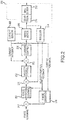
- FIG. 2 illustrates a block diagram of an aircraft electromechanical brake actuator control system in accordance with various embodiments.
- Block 205 includes mechanical components. The other blocks may be implemented on one or more controllers and/or controllers. For example, the blocks other than block 205 may be stored in a non-transitory storage medium and performed by a controller and/or controller, may be stored in a special-use controller, may be implemented in a field programmable gate array (FPGA), or the like.
- Block 205 includes a current sensor 208 coupled to an actuator motor 206 (similar to or the same as actuator motor 102A). Current sensor 208 is configured to detect an amount of current supplied to actuator motor 206.
- a resolver 214 is also coupled to actuator motor 206. Resolver 214 measures the rotational position and speed of actuator motor 206.
- Actuator motor 206 is also coupled to a gear transmission 210 and a ball screw 212.
- a force observer module 216 is coupled to block 205. Force observer module 216 is configured to estimate the force of actuator 104A based on data from current sensor 208 and/or resolver 214. Force observer module 216 may be a controller and/or controller or may be implemented in a controller and/or controller.
- the estimated force is compared with a force command signal.
- the output of block 217 is provided to a force position control module 200.
- Output from force position control module 200 is summed with the rotational speed of actuator motor 206 in block 201.
- the result of the summation in block 201 is provided to a velocity control module 202.
- the output from velocity control module 202 is summed with the detected current from current sensor 208 in block 203.
- the output from block 203 is provided to a current control module 204.
- the output of current control module 204 is provided to actuator motor 206 as a control signal.
- FIGs. 3A through 4 illustrate logic within force observer module 216 in accordance with various embodiments.
- the logic may be implemented in hardware and/or software.
- the logic may be stored as machine-readable instructions on a non-transitory memory and performed by a controller.
- the logic may be stored on a special-use controller or a field programmable gate array.
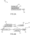
- FIG. 3A illustrates input parameters 390 to force observer module 216.
- Input parameters 390 may be known parameters for the given motor and thus be predetermined.
- Input parameters 390 include a max force 300, which may be measured in pound force (lbf), newtons, or the like.
- Max force 300 represents the maximum force that can be applied by actuator 205.
- Another input is a max current 302, which may be measured in amps.
- Max current 302 represents the amount of current to be applied to actuator motor 206 to cause actuator 205 to apply the maximum amount of force.
- Another input is an efficiency fraction 304.
- Efficiency fraction 304 indicates the efficiency of the actuator. In the example illustrated in FIG. 3A , max force 300 is given to be 7,857 pounds, max current 302 is given to be 6.5 amps and efficiency fraction 304 is given to be 0.65.
- FIG. 3B illustrates a system 391 for determining a constant K-nominal 306.
- K-nominal indicates a relationship between applied force and applied current for actuator motor 206, such that a current may be multiplied by K-nominal 306 to determine a force and a force can be divided by K-nominal 306 to determine a current.
- System 391 utilizes max force 300 and max current 302 as inputs. In block 305, the max force 300 is divided by the max current 302, resulting in K-nominal 306.
- FIG. 3B also illustrates a system 392 for determining a mode of actuator 205 of FIG. 2 .
- Plot 500 illustrates the estimated force using the methods described herein and plot 502 illustrates the measured force.
- plot 500 includes a first part 504 corresponding to a first mode, a second part 506 corresponding to a second mode and a third part 508 corresponding to a third mode.
- first mode the amount of current applied to actuator motor 206 is increasing and the force is increasing substantially proportionally.
- the amount of current applied to actuator motor 206 is decreasing a first amount.
- system 392 is designed to determine in which mode actuator 205 is operating.
- the system 392 utilizes input current 308 as an input.
- Input current 308 may be provided to system 392.
- Input current 308 is applied to calculate mode of operation block 310, which generates mode 312 as an output.
- Mode 312 indicates the mode in which actuator 205 is operating.
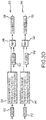
- FIG. 3C illustrates the logic within calculate mode of operation block 310.
- input current 308 is utilized as an input.
- the first portion of the calculate mode of operation block 310 is to calculate a filtered derivative of the current, or iDot 326.
- iDot 326 represents the estimated time rate of change that occurs in the derivative of current.
- Blocks 316, 318, 324, 322, 320 and 328 represent a low pass filtered differentiator used to calculate iDot 326.
- Block 320 is a simulation artifact and may not exist in various implementations.
- iDot 326 is then compared to zero in block 330, block 332 and block 334. If iDot 326 is greater than 0, then block 330 will output a 1, otherwise block 330 will output a 0. This 1 output corresponds to the first mode, indicating that the current is increasing and the force will increase proportionally to the current. If iDot 326 is equal to 0, then block 332 will output a 2. Otherwise, block 332 will output 0. This 2 output corresponds to the second mode, indicating that the force will not be greatly reduced as the current decreases. If iDot 326 is less than 0, then block 334 will output a 3. Otherwise, block 334 will output 0. The 3 output corresponds to the third mode, indicating that the force will be reduced substantially proportionately to the current as the current is reduced.
- Block 336 receives the input from block 330, block 332 and block 334 and adds them together. The resulting sum indicates the mode 312. If the mode is equal to 1, then actuator 205 is in the first mode. If the mode is equal to 2, then actuator 205 is operating in the second mode. If the mode is equal to 3, then actuator 205 is operating in the third mode.
- FIG. 3D illustrates a system 393 for determining a variable ForceMaxLimit 350, indicating the maximum force applied during the most recent iteration of the first mode. ForceMaxLimit 350 will be used in the force estimation during the second mode.
- the input to system 393 is mode 312.
- a true signal will be generated.
- the true signal generated from block 338 will cause a sample and hold block 346 to become active.
- Sample and hold block 346 also receives a force previous value (ForcePV 342) signal.
- ForcePV 342 represents an estimated force that has been delayed.
- a unit delay block 367 in a system 395 of FIG. 3E receives the estimated force and provides the estimated force as ForcePV 342 after a predetermined delay.
- sample and hold block 346 When block 338 outputs a true signal, sample and hold block 346 will store and output ForcePV 342 until a new true signal is generated in block 338. Sample and hold block 346 will generate the stored ForcePV 342 as ForceMAXLimit 350. ForceMAXLimit 350 corresponds to the maximum estimated force during the first mode or the second mode.
- FIG. 3D also illustrates a system 394 for calculating another variable, ForceMINLimit 352, indicating the minimum force applied during the most recent iteration of the third mode.
- ForceMINLimit 352 will be used in the force estimation during the second mode.
- Mode 312 is an input to system 394.
- a true signal is generated in response to the current beginning to increase.
- Sample and hold block 348 also receives ForcePV 342. When the output from block 340 is true, ForcePV 342 will be stored in block 348, and block 348 will output the value as ForceMINLimit 352 until a new "true" signal is generated in block 340.
- FIG. 3E illustrates a system 395 that is used to calculate an estimated force 380.
- Estimated force 380 is the output of system 395.
- Efficiency fraction 304 is a normalized value that ranges from 0 to 1. A value of one is ideal, meaning that actuator 205 is completely efficient and has no losses.
- the slope of first part 504 is equal to input current 308 multiplied by efficiency fraction 304.
- the slope of third part 508 is equal to input current 308 divided by efficiency fraction 304.
- input current 308 is multiplied by efficiency fraction 304.
- the output of block 354 represents the relationship of the current and force measurements during the first mode.
- input current 308 is divided by efficiency fraction 304. The resulting value represents the relationship of the current and the force during the third mode.
- Block 356 represents a case statement to be used for a selection of a relationship of the current and the force based on the mode.
- the mode 312 is provided as a selecting variable and the output of block 354 and block 376 are provided as selectable inputs.
- block 356 will output the output of block 354.
- block 356 will output the output of block 376.
- block 356 will output a value calculated elsewhere in system 395 (output of block 374).
- the output of block 356 is multiplied with K-nominal 306, the value calculated in system 391.
- K-nominal is multiplied with the output of block 356, the resulting signal indicates a force value.
- the value of force is stored as force 1 360.
- Block 368 will output a true signal if mode 312 is not equal to 1.
- the logic in block 368 is used to initialize system 395.
- Block 370 will output a true signal if ForceMAXLimit 350 is greater than 0. If block 370 and block 368 both output a true signal, then block 372 will output a true signal.
- Block 362 compares ForceMAXLimit 350 and force1 360 and outputs the smaller of the two signal values.
- Block 364 compares force1 360 and ForceMINLimit 352 and outputs the larger of the two signal values.
- block 366 While the output of block 372 is true, block 366 will output the signal generated in block 362. When the output of block 372 is false, block 366 will output the signal generated in block 364.
- the logic implemented in block 368, 370, 372, 362, 364 and 366 generates the estimated force when the mode is equal to 2.
- Block 378 is a limiter, which prevents the output of block 366 from dropping below 0.
- the output of block 378 is estimated force 380.
- the output of block 366 is driven through unit delay block 367, which delays the input signal (corresponding to the estimated force) by a predetermined period of time, such as one clock cycle, two clock cycles, 1 millisecond, etc.
- the output of block 367 is ForcePV 342, the previous value of the estimated force.
- ForcePV 342 is divided by K-nominal 306.
- the output of block 356 is multiplied by K-nominal 306 to result in a force value. Because ForcePV 342 is already a force value, it is divided by K-nominal 306 prior to entering case block 356 so that it can be converted back to a force value in block 358 via multiplication with K-nominal 306.
- FIG. 4 illustrates a closed-loop system 401 for estimating force applied by actuator 205.
- System 401 may be implemented in a machine-readable non-transitory medium and performed by a controller.
- system 401 may be implemented on a special use controller, FPGA or the like.
- system 401 may be implemented on more than one controller or controller.
- System 401 outputs ForceCL 408 as the closed-loop estimate of the force.
- ForceCL 408 is the output of force observer module 216.
- System 401 may also output an estimated current, indicated as iHatCL 416.
- ForceCL 408 and iHatCL 416 are determined based on input parameters 390 and Measured current 400.
- Measured current 400 represents the measured current, such as by current sensor 208 of FIG. 2 .
- Module 402 the difference between the Measured current 400 and iHatCL 416 is calculated.
- Module 404 represents a PI controller, which performs an integration function based on the difference calculated in module 402. Module 404 outputs a current value which will force measured current 400 and iHatCL 416 to become close in value.
- Module 406 represents a low pass filter.
- the low pass filter is used in order to reduce noise on the current signal generated in module 404.
- the output of module 406 is an adjusted current signal representing an adjusted current value.
- the adjusted current signal generated by the low pass filter will be provided to a current to force module 407.
- Current to force module 407 is a module capable of determining a force value based on a current value.
- current to force module 407 may be system 395.
- the adjusted current signal may be provided to system 395 as input current 308.
- Current to force module 407 will then output an estimated force 380 based on the adjusted current signal.
- the output of current to force module 407 at this point in the closed-loop system may be output as ForceCL 408, the estimated force of actuator 205.
- ForceCL 408 is then input into a force to current algorithm 409.
- a specific force to current algorithm 409 is illustrated.
- system 401 may operate with any algorithm that is capable of determining an estimated current based on a force value.
- force to current algorithm 409 converts ForceCL 408 into an estimated current, iHatCL 416.
- force to current algorithm 409 includes block 414, module 410, module 412 and current to force module 411.
- iHatCL 416 is provided to current to force module 411 as input current 308.
- Current to force module 411 acts the same as current to force module 407, and may also be performed by system 395.
- the output of current to force module 411 is a temporary estimated force.
- the temporary estimated force is then compared with ForceCL 408 in block 414.
- Block 414 outputs a force difference which is the difference in the temporary estimated force and ForceCL 408.
- module 410 the resulting difference of block 414 is amplified by 0.05.
- module 412 the result of module 410 is integrated.
- the result of module 412 is the estimated current, iHatCL 416.
- FIG. 5A illustrates plot 502 that represents a measured value of the force applied by actuator 205 as a current is applied to actuator motor 206 in accordance with various embodiments.
- Plot 500 represents the estimated value of the force using system 401. In FIG. 5A , up to 6.5 amps is applied to the actuator motor 206. As illustrated, the estimated force is similar to the measured force.
- FIG. 5B illustrates a plot 512 that represents the measured force when a current up to 3 amps is applied to actuator motor 206 in accordance with various embodiments.
- Plot 510 illustrates the estimated force using system 401. As illustrated, the estimated force is similar to the measured force during a first part 514 representing the first mode, a second part 516 representing the second mode and a third part 518 representing the third mode.
- FIG. 5C illustrates a plot 520 of time and current that represents both the actual current and the current estimated using system 401 in accordance with various embodiments.
- FIG. 5C also includes a plot 522 of time and current that illustrates the estimated current in a system similar to system 401 that is open-loop (i.e., not including module 402 and 404).
- the X axis represents time in seconds and the Y axis illustrates current in amps.
- the first segment 524 of FIG. 5 illustrates the current increasing as time progresses.
- both plot 520 and plot 522 represent similar estimated currents within first segment 524.
- both plot 520 and plot 522 illustrate that the estimated currents are similar.
- the open-loop estimation of current (plot 522) remains constant while the actual current and the closed-loop estimation of current (plot 520) decrease. This illustrates that the closed-loop estimation of current is more accurate than the open-loop estimation of current.
- the open-loop estimation of current again matches the actual current and the closed-loop estimation of current.
- references to "one embodiment”, “an embodiment”, “various embodiments”, etc. indicate that the embodiment described may include a particular feature, structure, or characteristic, but every embodiment may not necessarily include the particular feature, structure, or characteristic. Moreover, such phrases are not necessarily referring to the same embodiment. Further, when a particular feature, structure, or characteristic is described in connection with an embodiment, it is submitted that it is within the knowledge of one skilled in the art to affect such feature, structure, or characteristic in connection with other embodiments whether or not explicitly described. After reading the description, it will be apparent to one skilled in the relevant art(s) how to implement the disclosure in alternative embodiments.
Landscapes
- Engineering & Computer Science (AREA)
- Mechanical Engineering (AREA)
- General Engineering & Computer Science (AREA)
- Transportation (AREA)
- Aviation & Aerospace Engineering (AREA)
- Physics & Mathematics (AREA)
- General Physics & Mathematics (AREA)
- Control Of Electric Motors In General (AREA)
Claims (11)
- System zum Bestimmen einer Kraft, die durch einen Aktuator (206) auf eine äußere Scheibe (110) einer Flugzeugbremse ausgeübt wird, wobei das System umfasst:einen Stromsensor (208), der mit dem Aktuator (206) gekoppelt ist und konfiguriert ist, um eine erfasste Strommenge zu erfassen, die an den Aktuator (206) angelegt wird; undeine Steuerung, die mit dem Stromsensor (208) gekoppelt ist und konfiguriert ist zum:Bestimmen eines geschätzten Stroms,Empfangen der erfassten Strommenge,Bestimmen eines eingestellten Stroms basierend auf der erfassten Strommenge und dem geschätzten Strom, undBestimmen einer Schätzung der auf die äußere Scheibe (110) ausgeübten Kraft basierend auf dem eingestellten Strom;wobei das System dadurch gekennzeichnet ist, dass die Steuerung konfiguriert ist, um eine temporäre geschätzte Kraft basierend auf dem geschätzten Strom zu bestimmen; und dadurch,dass die Steuerung konfiguriert ist, um eine Differenz zwischen der temporären geschätzten Kraft und der Schätzung der Kraft zu bestimmen.
- System nach Anspruch 1, wobei die Steuerung ferner konfiguriert ist, um den eingestellten Strom unter Verwendung einer PI-Steuerung zu bestimmen, um eine Ausgabe zu erzeugen.
- System nach Anspruch 2, wobei die Steuerung ferner konfiguriert ist, um den eingestellten Strom durch Ausführen einer Tiefpassfilterung an der Ausgabe zu bestimmen.
- System nach Anspruch 1, wobei die Steuerung konfiguriert ist, um den geschätzten Strom basierend auf der Schätzung der Kraft zu bestimmen.
- System nach Anspruch 1, wobei die Steuerung konfiguriert ist, um eine Kraftdifferenz durch Multiplizieren der Differenz zwischen der temporären geschätzten Kraft und der Schätzung der Kraft mit einem konstanten Wert zu bestimmen.
- System nach Anspruch 5, wobei die Steuerung konfiguriert ist, um den geschätzten Strom durch Integrieren der Kraftdifferenz zu bestimmen.
- Verfahren zum Bestimmen einer Kraft, die durch einen Aktuator (206) auf eine äußere Scheibe (110) einer Flugzeugbremse ausgeübt wird, wobei das Verfahren umfasst:Bestimmen eines geschätzten Stroms durch eine Steuerung;Empfangen einer erfassten Strommenge an der Steuerung und durch einen Stromsensor (208);Bestimmen eines eingestellten Stroms durch die Steuerung basierend auf der erfassten Strommenge und dem geschätzten Strom; undBestimmen einer Schätzung der auf die äußere Scheibe ausgeübten Kraft basierend auf dem eingestellten Strom durch die Steuerung;wobei das Bestimmen des geschätzten Stroms das Bestimmen einer temporären geschätzten Kraft basierend auf dem geschätzten Strom umfasst;wobei das Bestimmen des geschätzten Stroms ferner das Bestimmen einer Differenz zwischen der temporären geschätzten Kraft und der Schätzung der Kraft umfasst.
- Verfahren nach Anspruch 7, wobei das Bestimmen des eingestellten Stroms unter Verwendung eines PI-Reglers durchgeführt wird, um eine Ausgabe zu erzeugen.
- Verfahren nach Anspruch 8, wobei das Bestimmen des eingestellten Stroms das Filtern der Ausgabe des PI-Reglers durch einen Tiefpassfilter umfasst.
- Verfahren nach Anspruch 7, wobei das Bestimmen des geschätzten Stroms das Bestimmen des geschätzten Stroms basierend auf der Schätzung der Kraft umfasst.
- Verfahren nach Anspruch 7, wobei das Bestimmen des geschätzten Stroms ferner das Bestimmen einer Kraftdifferenz durch Multiplizieren der Differenz zwischen der temporären geschätzten Kraft und der Schätzung der Kraft mit einem konstanten Wert und das Bestimmen des geschätzten Stroms durch Integrieren der Kraftdifferenz umfasst.
Applications Claiming Priority (1)
| Application Number | Priority Date | Filing Date | Title |
|---|---|---|---|
| US14/564,558 US9534971B2 (en) | 2014-12-09 | 2014-12-09 | Closed loop load force estimation systems and methods |
Publications (2)
| Publication Number | Publication Date |
|---|---|
| EP3031682A1 EP3031682A1 (de) | 2016-06-15 |
| EP3031682B1 true EP3031682B1 (de) | 2019-09-11 |
Family
ID=55024737
Family Applications (1)
| Application Number | Title | Priority Date | Filing Date |
|---|---|---|---|
| EP15198632.0A Active EP3031682B1 (de) | 2014-12-09 | 2015-12-09 | Geschlossene belastungskraftschätzungssysteme und verfahren |
Country Status (2)
| Country | Link |
|---|---|
| US (1) | US9534971B2 (de) |
| EP (1) | EP3031682B1 (de) |
Families Citing this family (4)
| Publication number | Priority date | Publication date | Assignee | Title |
|---|---|---|---|---|
| US9506826B2 (en) | 2014-12-09 | 2016-11-29 | Goodrich Corporation | Open loop load force estimation systems and methods |
| US9995353B2 (en) * | 2015-12-21 | 2018-06-12 | Goodrich Corporation | Modified actuator design to improve load distribution and damping |
| KR102047334B1 (ko) * | 2018-03-07 | 2019-11-21 | 재단법인대구경북과학기술원 | 구동기의 전동력 측정 시스템 및 방법 |
| US20250145129A1 (en) * | 2023-11-08 | 2025-05-08 | Goodrich Corporation | Force control for an electromechanical brake actuator |
Family Cites Families (23)
| Publication number | Priority date | Publication date | Assignee | Title |
|---|---|---|---|---|
| US4577497A (en) * | 1983-11-11 | 1986-03-25 | Vickers Public Limited Company | Dynamometers |
| US6003640A (en) | 1997-05-09 | 1999-12-21 | The B.F. Goodrich Company | Electronic braking system with brake wear measurement and running clearance adjustment |
| WO1999026822A1 (de) | 1997-11-22 | 1999-06-03 | Continental Teves Ag & Co. Ohg | Elektromechanisches bremssystem |
| US6371256B2 (en) * | 1999-12-14 | 2002-04-16 | Delphi Technologies, Inc | Electric disc brake caliper controls |
| WO2001068428A1 (de) * | 2000-03-15 | 2001-09-20 | Continental Teves Ag & Co. Ohg | Verfahren und regelsystem zum aufbringen definierter spannkräfte |
| EP1826081B1 (de) | 2003-10-15 | 2011-04-20 | Honeywell Inc. | Verfahren zur Verstärkung eines Motorsollmoments bei transienter Positionsabweichung |
| US20060108867A1 (en) | 2004-09-17 | 2006-05-25 | Mihai Ralea | Electromechanical braking system with electrical energy back-up and regenerative energy management |
| DE102005030618A1 (de) * | 2004-10-13 | 2006-04-20 | Knorr-Bremse Systeme für Nutzfahrzeuge GmbH | Scheibenbremse in selbstverstärkender Bauart und Ansteuerverfahren für eine selbstverstärkende Bremse |
| US7317981B2 (en) | 2004-11-19 | 2008-01-08 | Honeywell International, Inc. | Aircraft brake actuation system and method including anti-hysteresis control |
| FR2882541B1 (fr) | 2005-02-25 | 2009-01-16 | Messier Bugatti Sa | Procede d'asservissement dans un systeme de freinage de vehicule a freins electriques |
| FR2888917B1 (fr) | 2005-07-21 | 2009-11-20 | Valeo Vision | Dispositif d'eclairage ou de signalisation, notamment pour vehicule automobile |
| EP1746399A1 (de) | 2005-07-22 | 2007-01-24 | Delphi Technologies, Inc. | Abschätzung der Kraft/Drehmoment, der gegen einen electromotorischen Stellantrieb von einer Last ausgeübt wird |
| WO2007120267A2 (en) | 2005-11-30 | 2007-10-25 | Goodrich Corporation | Controller for electromechanical braking system with power demand limitation and method |
| US7353101B2 (en) | 2006-04-18 | 2008-04-01 | Honeywell International Inc. | Methods and apparatus to control electro-mechanical brakes |
| US7630813B2 (en) | 2006-06-06 | 2009-12-08 | Delphi Technologies, Inc. | Method for controlling electromechanical brakes using parameter identification and no additional sensors |
| JP2010203561A (ja) | 2009-03-05 | 2010-09-16 | Kayaba Ind Co Ltd | 電動ブレーキ |
| US8180548B2 (en) | 2009-04-24 | 2012-05-15 | Goodrich Corporation | Deceleration controlled braking |
| US20100292889A1 (en) * | 2009-05-14 | 2010-11-18 | Cahill Eric D | Brake operation built-in test equipment |
| US8393203B2 (en) * | 2010-03-08 | 2013-03-12 | Goodrich Corporation | Systems and methods for built in test equipment for a brake control system |
| US9028014B2 (en) | 2010-12-08 | 2015-05-12 | Goodrich Corporation | System and method for providing indication of braking for electric brakes |
| US9669810B2 (en) | 2012-01-10 | 2017-06-06 | Honeywell International Inc. | Brake assembly including independently activatable brake actuators |
| CN105008195B (zh) | 2013-03-06 | 2018-10-02 | 庞巴迪公司 | 依赖于所应用的制动电力控制的电压滞后的电制动系统和方法 |
| US9506826B2 (en) | 2014-12-09 | 2016-11-29 | Goodrich Corporation | Open loop load force estimation systems and methods |
-
2014
- 2014-12-09 US US14/564,558 patent/US9534971B2/en active Active
-
2015
- 2015-12-09 EP EP15198632.0A patent/EP3031682B1/de active Active
Non-Patent Citations (1)
| Title |
|---|
| None * |
Also Published As
| Publication number | Publication date |
|---|---|
| US20160161352A1 (en) | 2016-06-09 |
| EP3031682A1 (de) | 2016-06-15 |
| US9534971B2 (en) | 2017-01-03 |
Similar Documents
| Publication | Publication Date | Title |
|---|---|---|
| EP3031682A1 (de) | Geschlossene belastungskraftschätzungssysteme und verfahren | |
| EP3156294B1 (de) | Verfahren zur steuerung eines feststellbremssystems | |
| CN104859624B (zh) | 用于调整车辆中的驻车制动器的方法 | |
| US9701290B2 (en) | Method and apparatus for operating a braking device, braking device | |
| US9475471B2 (en) | Braking control apparatus for vehicle | |
| EP3072759B1 (de) | Bremskraftmesstechniken | |
| US10486666B2 (en) | Method for determining a position and/or change in position of a hydraulic pump of a motor vehicle brake system and motor vehicle brake system | |
| JP6811101B2 (ja) | 電動パーキングブレーキ装置、及びブレーキ装置 | |
| EP3032234B1 (de) | Systeme und verfahren zur schätzung der lastkraft mit offener schleife | |
| US9260099B2 (en) | Method for adjusting a parking brake in a vehicle | |
| EP1746399A1 (de) | Abschätzung der Kraft/Drehmoment, der gegen einen electromotorischen Stellantrieb von einer Last ausgeübt wird | |
| EP3109108B1 (de) | Systeme und verfahren zur elektrischen bremskraftschätzung mit antriebsstranghaftreibungstoleranz | |
| CN105523027A (zh) | 用于运行制动机构的方法和装置,制动机构 | |
| JP2013227975A (ja) | 遠心ポンプを認識及び制御する方法並びにシステム | |
| KR20160021574A (ko) | 긴급제동 발생시 3상 모터 제어를 위한 확장된 전류 검출 방법 | |
| KR101315782B1 (ko) | 전자식 주차 브레이크 시스템의 제동력 제어방법 | |
| US11565671B2 (en) | Method for monitoring an electric motor, electronic control module, hydraulic brake system and storage medium | |
| JP2020093721A (ja) | 電動ブレーキ装置 | |
| US20200086834A1 (en) | Method and Device for Operating an Automated Parking Brake | |
| US20200028457A1 (en) | Motor driving control device and motor driving control method | |
| KR102439814B1 (ko) | 전동기 속도 추정 장치 및 방법 | |
| JP7155055B2 (ja) | 電動パーキングブレーキ装置 | |
| EP3434541A1 (de) | System und verfahren zur emi-reduktion in einem elektrischen bremssystem | |
| WO2019093030A1 (ja) | 電動パーキングブレーキ装置、及び電動ブレーキ装置 | |
| CN102371987A (zh) | 机动车中能够电气操纵的驻车制动器的效率的求取方法 |
Legal Events
| Date | Code | Title | Description |
|---|---|---|---|
| PUAI | Public reference made under article 153(3) epc to a published international application that has entered the european phase |
Free format text: ORIGINAL CODE: 0009012 |
|
| AK | Designated contracting states |
Kind code of ref document: A1 Designated state(s): AL AT BE BG CH CY CZ DE DK EE ES FI FR GB GR HR HU IE IS IT LI LT LU LV MC MK MT NL NO PL PT RO RS SE SI SK SM TR |
|
| AX | Request for extension of the european patent |
Extension state: BA ME |
|
| STAA | Information on the status of an ep patent application or granted ep patent |
Free format text: STATUS: REQUEST FOR EXAMINATION WAS MADE |
|
| 17P | Request for examination filed |
Effective date: 20161208 |
|
| RBV | Designated contracting states (corrected) |
Designated state(s): AL AT BE BG CH CY CZ DE DK EE ES FI FR GB GR HR HU IE IS IT LI LT LU LV MC MK MT NL NO PL PT RO RS SE SI SK SM TR |
|
| GRAP | Despatch of communication of intention to grant a patent |
Free format text: ORIGINAL CODE: EPIDOSNIGR1 |
|
| STAA | Information on the status of an ep patent application or granted ep patent |
Free format text: STATUS: GRANT OF PATENT IS INTENDED |
|
| INTG | Intention to grant announced |
Effective date: 20190402 |
|
| GRAS | Grant fee paid |
Free format text: ORIGINAL CODE: EPIDOSNIGR3 |
|
| GRAA | (expected) grant |
Free format text: ORIGINAL CODE: 0009210 |
|
| STAA | Information on the status of an ep patent application or granted ep patent |
Free format text: STATUS: THE PATENT HAS BEEN GRANTED |
|
| AK | Designated contracting states |
Kind code of ref document: B1 Designated state(s): AL AT BE BG CH CY CZ DE DK EE ES FI FR GB GR HR HU IE IS IT LI LT LU LV MC MK MT NL NO PL PT RO RS SE SI SK SM TR |
|
| REG | Reference to a national code |
Ref country code: GB Ref legal event code: FG4D |
|
| REG | Reference to a national code |
Ref country code: CH Ref legal event code: EP |
|
| REG | Reference to a national code |
Ref country code: AT Ref legal event code: REF Ref document number: 1178044 Country of ref document: AT Kind code of ref document: T Effective date: 20190915 |
|
| REG | Reference to a national code |
Ref country code: DE Ref legal event code: R096 Ref document number: 602015037684 Country of ref document: DE |
|
| REG | Reference to a national code |
Ref country code: IE Ref legal event code: FG4D |
|
| REG | Reference to a national code |
Ref country code: NL Ref legal event code: MP Effective date: 20190911 |
|
| REG | Reference to a national code |
Ref country code: LT Ref legal event code: MG4D |
|
| PG25 | Lapsed in a contracting state [announced via postgrant information from national office to epo] |
Ref country code: FI Free format text: LAPSE BECAUSE OF FAILURE TO SUBMIT A TRANSLATION OF THE DESCRIPTION OR TO PAY THE FEE WITHIN THE PRESCRIBED TIME-LIMIT Effective date: 20190911 Ref country code: HR Free format text: LAPSE BECAUSE OF FAILURE TO SUBMIT A TRANSLATION OF THE DESCRIPTION OR TO PAY THE FEE WITHIN THE PRESCRIBED TIME-LIMIT Effective date: 20190911 Ref country code: SE Free format text: LAPSE BECAUSE OF FAILURE TO SUBMIT A TRANSLATION OF THE DESCRIPTION OR TO PAY THE FEE WITHIN THE PRESCRIBED TIME-LIMIT Effective date: 20190911 Ref country code: NO Free format text: LAPSE BECAUSE OF FAILURE TO SUBMIT A TRANSLATION OF THE DESCRIPTION OR TO PAY THE FEE WITHIN THE PRESCRIBED TIME-LIMIT Effective date: 20191211 Ref country code: BG Free format text: LAPSE BECAUSE OF FAILURE TO SUBMIT A TRANSLATION OF THE DESCRIPTION OR TO PAY THE FEE WITHIN THE PRESCRIBED TIME-LIMIT Effective date: 20191211 Ref country code: LT Free format text: LAPSE BECAUSE OF FAILURE TO SUBMIT A TRANSLATION OF THE DESCRIPTION OR TO PAY THE FEE WITHIN THE PRESCRIBED TIME-LIMIT Effective date: 20190911 |
|
| PG25 | Lapsed in a contracting state [announced via postgrant information from national office to epo] |
Ref country code: ES Free format text: LAPSE BECAUSE OF FAILURE TO SUBMIT A TRANSLATION OF THE DESCRIPTION OR TO PAY THE FEE WITHIN THE PRESCRIBED TIME-LIMIT Effective date: 20190911 Ref country code: GR Free format text: LAPSE BECAUSE OF FAILURE TO SUBMIT A TRANSLATION OF THE DESCRIPTION OR TO PAY THE FEE WITHIN THE PRESCRIBED TIME-LIMIT Effective date: 20191212 Ref country code: LV Free format text: LAPSE BECAUSE OF FAILURE TO SUBMIT A TRANSLATION OF THE DESCRIPTION OR TO PAY THE FEE WITHIN THE PRESCRIBED TIME-LIMIT Effective date: 20190911 Ref country code: AL Free format text: LAPSE BECAUSE OF FAILURE TO SUBMIT A TRANSLATION OF THE DESCRIPTION OR TO PAY THE FEE WITHIN THE PRESCRIBED TIME-LIMIT Effective date: 20190911 Ref country code: RS Free format text: LAPSE BECAUSE OF FAILURE TO SUBMIT A TRANSLATION OF THE DESCRIPTION OR TO PAY THE FEE WITHIN THE PRESCRIBED TIME-LIMIT Effective date: 20190911 |
|
| REG | Reference to a national code |
Ref country code: AT Ref legal event code: MK05 Ref document number: 1178044 Country of ref document: AT Kind code of ref document: T Effective date: 20190911 |
|
| PG25 | Lapsed in a contracting state [announced via postgrant information from national office to epo] |
Ref country code: PL Free format text: LAPSE BECAUSE OF FAILURE TO SUBMIT A TRANSLATION OF THE DESCRIPTION OR TO PAY THE FEE WITHIN THE PRESCRIBED TIME-LIMIT Effective date: 20190911 Ref country code: EE Free format text: LAPSE BECAUSE OF FAILURE TO SUBMIT A TRANSLATION OF THE DESCRIPTION OR TO PAY THE FEE WITHIN THE PRESCRIBED TIME-LIMIT Effective date: 20190911 Ref country code: AT Free format text: LAPSE BECAUSE OF FAILURE TO SUBMIT A TRANSLATION OF THE DESCRIPTION OR TO PAY THE FEE WITHIN THE PRESCRIBED TIME-LIMIT Effective date: 20190911 Ref country code: RO Free format text: LAPSE BECAUSE OF FAILURE TO SUBMIT A TRANSLATION OF THE DESCRIPTION OR TO PAY THE FEE WITHIN THE PRESCRIBED TIME-LIMIT Effective date: 20190911 Ref country code: NL Free format text: LAPSE BECAUSE OF FAILURE TO SUBMIT A TRANSLATION OF THE DESCRIPTION OR TO PAY THE FEE WITHIN THE PRESCRIBED TIME-LIMIT Effective date: 20190911 Ref country code: PT Free format text: LAPSE BECAUSE OF FAILURE TO SUBMIT A TRANSLATION OF THE DESCRIPTION OR TO PAY THE FEE WITHIN THE PRESCRIBED TIME-LIMIT Effective date: 20200113 Ref country code: IT Free format text: LAPSE BECAUSE OF FAILURE TO SUBMIT A TRANSLATION OF THE DESCRIPTION OR TO PAY THE FEE WITHIN THE PRESCRIBED TIME-LIMIT Effective date: 20190911 |
|
| PG25 | Lapsed in a contracting state [announced via postgrant information from national office to epo] |
Ref country code: SK Free format text: LAPSE BECAUSE OF FAILURE TO SUBMIT A TRANSLATION OF THE DESCRIPTION OR TO PAY THE FEE WITHIN THE PRESCRIBED TIME-LIMIT Effective date: 20190911 Ref country code: CZ Free format text: LAPSE BECAUSE OF FAILURE TO SUBMIT A TRANSLATION OF THE DESCRIPTION OR TO PAY THE FEE WITHIN THE PRESCRIBED TIME-LIMIT Effective date: 20190911 Ref country code: SM Free format text: LAPSE BECAUSE OF FAILURE TO SUBMIT A TRANSLATION OF THE DESCRIPTION OR TO PAY THE FEE WITHIN THE PRESCRIBED TIME-LIMIT Effective date: 20190911 Ref country code: IS Free format text: LAPSE BECAUSE OF FAILURE TO SUBMIT A TRANSLATION OF THE DESCRIPTION OR TO PAY THE FEE WITHIN THE PRESCRIBED TIME-LIMIT Effective date: 20200224 |
|
| REG | Reference to a national code |
Ref country code: DE Ref legal event code: R097 Ref document number: 602015037684 Country of ref document: DE |
|
| REG | Reference to a national code |
Ref country code: DE Ref legal event code: R119 Ref document number: 602015037684 Country of ref document: DE |
|
| PLBE | No opposition filed within time limit |
Free format text: ORIGINAL CODE: 0009261 |
|
| STAA | Information on the status of an ep patent application or granted ep patent |
Free format text: STATUS: NO OPPOSITION FILED WITHIN TIME LIMIT |
|
| PG2D | Information on lapse in contracting state deleted |
Ref country code: IS |
|
| PG25 | Lapsed in a contracting state [announced via postgrant information from national office to epo] |
Ref country code: DK Free format text: LAPSE BECAUSE OF FAILURE TO SUBMIT A TRANSLATION OF THE DESCRIPTION OR TO PAY THE FEE WITHIN THE PRESCRIBED TIME-LIMIT Effective date: 20190911 Ref country code: IS Free format text: LAPSE BECAUSE OF FAILURE TO SUBMIT A TRANSLATION OF THE DESCRIPTION OR TO PAY THE FEE WITHIN THE PRESCRIBED TIME-LIMIT Effective date: 20200112 |
|
| REG | Reference to a national code |
Ref country code: CH Ref legal event code: PL |
|
| 26N | No opposition filed |
Effective date: 20200615 |
|
| REG | Reference to a national code |
Ref country code: BE Ref legal event code: MM Effective date: 20191231 |
|
| PG25 | Lapsed in a contracting state [announced via postgrant information from national office to epo] |
Ref country code: SI Free format text: LAPSE BECAUSE OF FAILURE TO SUBMIT A TRANSLATION OF THE DESCRIPTION OR TO PAY THE FEE WITHIN THE PRESCRIBED TIME-LIMIT Effective date: 20190911 Ref country code: MC Free format text: LAPSE BECAUSE OF FAILURE TO SUBMIT A TRANSLATION OF THE DESCRIPTION OR TO PAY THE FEE WITHIN THE PRESCRIBED TIME-LIMIT Effective date: 20190911 |
|
| PG25 | Lapsed in a contracting state [announced via postgrant information from national office to epo] |
Ref country code: LU Free format text: LAPSE BECAUSE OF NON-PAYMENT OF DUE FEES Effective date: 20191209 Ref country code: DE Free format text: LAPSE BECAUSE OF NON-PAYMENT OF DUE FEES Effective date: 20200701 Ref country code: IE Free format text: LAPSE BECAUSE OF NON-PAYMENT OF DUE FEES Effective date: 20191209 |
|
| PG25 | Lapsed in a contracting state [announced via postgrant information from national office to epo] |
Ref country code: CH Free format text: LAPSE BECAUSE OF NON-PAYMENT OF DUE FEES Effective date: 20191231 Ref country code: BE Free format text: LAPSE BECAUSE OF NON-PAYMENT OF DUE FEES Effective date: 20191231 Ref country code: LI Free format text: LAPSE BECAUSE OF NON-PAYMENT OF DUE FEES Effective date: 20191231 |
|
| PG25 | Lapsed in a contracting state [announced via postgrant information from national office to epo] |
Ref country code: CY Free format text: LAPSE BECAUSE OF FAILURE TO SUBMIT A TRANSLATION OF THE DESCRIPTION OR TO PAY THE FEE WITHIN THE PRESCRIBED TIME-LIMIT Effective date: 20190911 |
|
| PG25 | Lapsed in a contracting state [announced via postgrant information from national office to epo] |
Ref country code: MT Free format text: LAPSE BECAUSE OF FAILURE TO SUBMIT A TRANSLATION OF THE DESCRIPTION OR TO PAY THE FEE WITHIN THE PRESCRIBED TIME-LIMIT Effective date: 20190911 Ref country code: HU Free format text: LAPSE BECAUSE OF FAILURE TO SUBMIT A TRANSLATION OF THE DESCRIPTION OR TO PAY THE FEE WITHIN THE PRESCRIBED TIME-LIMIT; INVALID AB INITIO Effective date: 20151209 |
|
| PG25 | Lapsed in a contracting state [announced via postgrant information from national office to epo] |
Ref country code: TR Free format text: LAPSE BECAUSE OF FAILURE TO SUBMIT A TRANSLATION OF THE DESCRIPTION OR TO PAY THE FEE WITHIN THE PRESCRIBED TIME-LIMIT Effective date: 20190911 |
|
| PG25 | Lapsed in a contracting state [announced via postgrant information from national office to epo] |
Ref country code: MK Free format text: LAPSE BECAUSE OF FAILURE TO SUBMIT A TRANSLATION OF THE DESCRIPTION OR TO PAY THE FEE WITHIN THE PRESCRIBED TIME-LIMIT Effective date: 20190911 |
|
| P01 | Opt-out of the competence of the unified patent court (upc) registered |
Effective date: 20230522 |
|
| PGFP | Annual fee paid to national office [announced via postgrant information from national office to epo] |
Ref country code: GB Payment date: 20251120 Year of fee payment: 11 |
|
| PGFP | Annual fee paid to national office [announced via postgrant information from national office to epo] |
Ref country code: FR Payment date: 20251120 Year of fee payment: 11 |