EP3031577A1 - Polishing tool and processing method for member - Google Patents
Polishing tool and processing method for member Download PDFInfo
- Publication number
- EP3031577A1 EP3031577A1 EP14834968.1A EP14834968A EP3031577A1 EP 3031577 A1 EP3031577 A1 EP 3031577A1 EP 14834968 A EP14834968 A EP 14834968A EP 3031577 A1 EP3031577 A1 EP 3031577A1
- Authority
- EP
- European Patent Office
- Prior art keywords
- polishing
- polished
- curved surface
- polishing tool
- tool
- Prior art date
- Legal status (The legal status is an assumption and is not a legal conclusion. Google has not performed a legal analysis and makes no representation as to the accuracy of the status listed.)
- Withdrawn
Links
- 238000005498 polishing Methods 0.000 title claims abstract description 280
- 238000003672 processing method Methods 0.000 title claims description 6
- 238000000034 method Methods 0.000 claims abstract description 20
- 239000007788 liquid Substances 0.000 claims description 28
- 238000003825 pressing Methods 0.000 claims description 10
- 239000006061 abrasive grain Substances 0.000 claims description 6
- 239000006185 dispersion Substances 0.000 claims description 4
- 229920005989 resin Polymers 0.000 abstract description 8
- 239000011347 resin Substances 0.000 abstract description 8
- 229920003002 synthetic resin Polymers 0.000 abstract description 6
- 239000000057 synthetic resin Substances 0.000 abstract description 6
- 239000004745 nonwoven fabric Substances 0.000 abstract description 4
- 239000002131 composite material Substances 0.000 abstract description 2
- 239000004744 fabric Substances 0.000 abstract description 2
- 239000006260 foam Substances 0.000 abstract description 2
- 239000002649 leather substitute Substances 0.000 abstract description 2
- 239000000463 material Substances 0.000 description 12
- 238000010586 diagram Methods 0.000 description 8
- 239000000919 ceramic Substances 0.000 description 6
- 229910052751 metal Inorganic materials 0.000 description 5
- 239000002184 metal Substances 0.000 description 5
- XEEYBQQBJWHFJM-UHFFFAOYSA-N Iron Chemical compound [Fe] XEEYBQQBJWHFJM-UHFFFAOYSA-N 0.000 description 4
- UQSXHKLRYXJYBZ-UHFFFAOYSA-N Iron oxide Chemical compound [Fe]=O UQSXHKLRYXJYBZ-UHFFFAOYSA-N 0.000 description 4
- PXHVJJICTQNCMI-UHFFFAOYSA-N Nickel Chemical compound [Ni] PXHVJJICTQNCMI-UHFFFAOYSA-N 0.000 description 4
- XUIMIQQOPSSXEZ-UHFFFAOYSA-N Silicon Chemical compound [Si] XUIMIQQOPSSXEZ-UHFFFAOYSA-N 0.000 description 4
- 229910052782 aluminium Inorganic materials 0.000 description 4
- XAGFODPZIPBFFR-UHFFFAOYSA-N aluminium Chemical compound [Al] XAGFODPZIPBFFR-UHFFFAOYSA-N 0.000 description 4
- AMWRITDGCCNYAT-UHFFFAOYSA-L hydroxy(oxo)manganese;manganese Chemical compound [Mn].O[Mn]=O.O[Mn]=O AMWRITDGCCNYAT-UHFFFAOYSA-L 0.000 description 4
- 150000004767 nitrides Chemical class 0.000 description 4
- -1 polyethylene Polymers 0.000 description 4
- 229910052710 silicon Inorganic materials 0.000 description 4
- 239000010703 silicon Substances 0.000 description 4
- VYPSYNLAJGMNEJ-UHFFFAOYSA-N Silicium dioxide Chemical compound O=[Si]=O VYPSYNLAJGMNEJ-UHFFFAOYSA-N 0.000 description 3
- TWNQGVIAIRXVLR-UHFFFAOYSA-N oxo(oxoalumanyloxy)alumane Chemical compound O=[Al]O[Al]=O TWNQGVIAIRXVLR-UHFFFAOYSA-N 0.000 description 3
- RVTZCBVAJQQJTK-UHFFFAOYSA-N oxygen(2-);zirconium(4+) Chemical compound [O-2].[O-2].[Zr+4] RVTZCBVAJQQJTK-UHFFFAOYSA-N 0.000 description 3
- HBMJWWWQQXIZIP-UHFFFAOYSA-N silicon carbide Chemical compound [Si+]#[C-] HBMJWWWQQXIZIP-UHFFFAOYSA-N 0.000 description 3
- 229910010271 silicon carbide Inorganic materials 0.000 description 3
- 229910052814 silicon oxide Inorganic materials 0.000 description 3
- 229920005992 thermoplastic resin Polymers 0.000 description 3
- 229910001928 zirconium oxide Inorganic materials 0.000 description 3
- 229920000178 Acrylic resin Polymers 0.000 description 2
- 239000004925 Acrylic resin Substances 0.000 description 2
- OYPRJOBELJOOCE-UHFFFAOYSA-N Calcium Chemical compound [Ca] OYPRJOBELJOOCE-UHFFFAOYSA-N 0.000 description 2
- RTZKZFJDLAIYFH-UHFFFAOYSA-N Diethyl ether Chemical compound CCOCC RTZKZFJDLAIYFH-UHFFFAOYSA-N 0.000 description 2
- FYYHWMGAXLPEAU-UHFFFAOYSA-N Magnesium Chemical compound [Mg] FYYHWMGAXLPEAU-UHFFFAOYSA-N 0.000 description 2
- 239000004952 Polyamide Substances 0.000 description 2
- 239000004698 Polyethylene Substances 0.000 description 2
- 239000004642 Polyimide Substances 0.000 description 2
- 239000004743 Polypropylene Substances 0.000 description 2
- GWEVSGVZZGPLCZ-UHFFFAOYSA-N Titan oxide Chemical compound O=[Ti]=O GWEVSGVZZGPLCZ-UHFFFAOYSA-N 0.000 description 2
- RTAQQCXQSZGOHL-UHFFFAOYSA-N Titanium Chemical compound [Ti] RTAQQCXQSZGOHL-UHFFFAOYSA-N 0.000 description 2
- WGLPBDUCMAPZCE-UHFFFAOYSA-N Trioxochromium Chemical compound O=[Cr](=O)=O WGLPBDUCMAPZCE-UHFFFAOYSA-N 0.000 description 2
- HCHKCACWOHOZIP-UHFFFAOYSA-N Zinc Chemical compound [Zn] HCHKCACWOHOZIP-UHFFFAOYSA-N 0.000 description 2
- QCWXUUIWCKQGHC-UHFFFAOYSA-N Zirconium Chemical compound [Zr] QCWXUUIWCKQGHC-UHFFFAOYSA-N 0.000 description 2
- 239000000956 alloy Substances 0.000 description 2
- 229910045601 alloy Inorganic materials 0.000 description 2
- 229910052788 barium Inorganic materials 0.000 description 2
- DSAJWYNOEDNPEQ-UHFFFAOYSA-N barium atom Chemical compound [Ba] DSAJWYNOEDNPEQ-UHFFFAOYSA-N 0.000 description 2
- 229910052791 calcium Inorganic materials 0.000 description 2
- 239000011575 calcium Substances 0.000 description 2
- BRPQOXSCLDDYGP-UHFFFAOYSA-N calcium oxide Chemical compound [O-2].[Ca+2] BRPQOXSCLDDYGP-UHFFFAOYSA-N 0.000 description 2
- 239000000292 calcium oxide Substances 0.000 description 2
- ODINCKMPIJJUCX-UHFFFAOYSA-N calcium oxide Inorganic materials [Ca]=O ODINCKMPIJJUCX-UHFFFAOYSA-N 0.000 description 2
- 229910000420 cerium oxide Inorganic materials 0.000 description 2
- 239000003795 chemical substances by application Substances 0.000 description 2
- 229910000423 chromium oxide Inorganic materials 0.000 description 2
- 238000007796 conventional method Methods 0.000 description 2
- 229910003460 diamond Inorganic materials 0.000 description 2
- 239000010432 diamond Substances 0.000 description 2
- 239000003822 epoxy resin Substances 0.000 description 2
- 239000011521 glass Substances 0.000 description 2
- 229910052742 iron Inorganic materials 0.000 description 2
- 229910052749 magnesium Inorganic materials 0.000 description 2
- 239000011777 magnesium Substances 0.000 description 2
- 239000000395 magnesium oxide Substances 0.000 description 2
- CPLXHLVBOLITMK-UHFFFAOYSA-N magnesium oxide Inorganic materials [Mg]=O CPLXHLVBOLITMK-UHFFFAOYSA-N 0.000 description 2
- AXZKOIWUVFPNLO-UHFFFAOYSA-N magnesium;oxygen(2-) Chemical compound [O-2].[Mg+2] AXZKOIWUVFPNLO-UHFFFAOYSA-N 0.000 description 2
- WPBNNNQJVZRUHP-UHFFFAOYSA-L manganese(2+);methyl n-[[2-(methoxycarbonylcarbamothioylamino)phenyl]carbamothioyl]carbamate;n-[2-(sulfidocarbothioylamino)ethyl]carbamodithioate Chemical compound [Mn+2].[S-]C(=S)NCCNC([S-])=S.COC(=O)NC(=S)NC1=CC=CC=C1NC(=S)NC(=O)OC WPBNNNQJVZRUHP-UHFFFAOYSA-L 0.000 description 2
- 229910044991 metal oxide Inorganic materials 0.000 description 2
- 150000004706 metal oxides Chemical class 0.000 description 2
- 150000002739 metals Chemical class 0.000 description 2
- 239000000203 mixture Substances 0.000 description 2
- 229910052759 nickel Inorganic materials 0.000 description 2
- BMMGVYCKOGBVEV-UHFFFAOYSA-N oxo(oxoceriooxy)cerium Chemical compound [Ce]=O.O=[Ce]=O BMMGVYCKOGBVEV-UHFFFAOYSA-N 0.000 description 2
- 239000002245 particle Substances 0.000 description 2
- 239000005011 phenolic resin Substances 0.000 description 2
- 229920002647 polyamide Polymers 0.000 description 2
- 229920000515 polycarbonate Polymers 0.000 description 2
- 239000004417 polycarbonate Substances 0.000 description 2
- 229920000647 polyepoxide Polymers 0.000 description 2
- 229920000573 polyethylene Polymers 0.000 description 2
- 229920001721 polyimide Polymers 0.000 description 2
- 229920001155 polypropylene Polymers 0.000 description 2
- 238000011084 recovery Methods 0.000 description 2
- 229920002803 thermoplastic polyurethane Polymers 0.000 description 2
- 229920001187 thermosetting polymer Polymers 0.000 description 2
- 239000010936 titanium Substances 0.000 description 2
- 229910052719 titanium Inorganic materials 0.000 description 2
- OGIDPMRJRNCKJF-UHFFFAOYSA-N titanium oxide Inorganic materials [Ti]=O OGIDPMRJRNCKJF-UHFFFAOYSA-N 0.000 description 2
- 239000011701 zinc Substances 0.000 description 2
- 229910052725 zinc Inorganic materials 0.000 description 2
- 229910052726 zirconium Inorganic materials 0.000 description 2
- 229910052582 BN Inorganic materials 0.000 description 1
- PZNSFCLAULLKQX-UHFFFAOYSA-N Boron nitride Chemical compound N#B PZNSFCLAULLKQX-UHFFFAOYSA-N 0.000 description 1
- RYGMFSIKBFXOCR-UHFFFAOYSA-N Copper Chemical compound [Cu] RYGMFSIKBFXOCR-UHFFFAOYSA-N 0.000 description 1
- 229910052581 Si3N4 Inorganic materials 0.000 description 1
- 239000000654 additive Substances 0.000 description 1
- 230000000996 additive effect Effects 0.000 description 1
- 230000002421 anti-septic effect Effects 0.000 description 1
- 239000003963 antioxidant agent Substances 0.000 description 1
- 230000003078 antioxidant effect Effects 0.000 description 1
- 229910017052 cobalt Inorganic materials 0.000 description 1
- 239000010941 cobalt Substances 0.000 description 1
- GUTLYIVDDKVIGB-UHFFFAOYSA-N cobalt atom Chemical compound [Co] GUTLYIVDDKVIGB-UHFFFAOYSA-N 0.000 description 1
- RYTYSMSQNNBZDP-UHFFFAOYSA-N cobalt copper Chemical compound [Co].[Cu] RYTYSMSQNNBZDP-UHFFFAOYSA-N 0.000 description 1
- 239000008139 complexing agent Substances 0.000 description 1
- 229910052802 copper Inorganic materials 0.000 description 1
- 239000010949 copper Substances 0.000 description 1
- 230000003247 decreasing effect Effects 0.000 description 1
- 239000002270 dispersing agent Substances 0.000 description 1
- 230000000694 effects Effects 0.000 description 1
- 230000005489 elastic deformation Effects 0.000 description 1
- 239000003995 emulsifying agent Substances 0.000 description 1
- 238000005530 etching Methods 0.000 description 1
- 230000000855 fungicidal effect Effects 0.000 description 1
- 239000000417 fungicide Substances 0.000 description 1
- 238000007542 hardness measurement Methods 0.000 description 1
- 238000003754 machining Methods 0.000 description 1
- 238000000465 moulding Methods 0.000 description 1
- 239000003921 oil Substances 0.000 description 1
- 239000011146 organic particle Substances 0.000 description 1
- 239000007800 oxidant agent Substances 0.000 description 1
- 230000001590 oxidative effect Effects 0.000 description 1
- 239000003002 pH adjusting agent Substances 0.000 description 1
- 230000001681 protective effect Effects 0.000 description 1
- HQVNEWCFYHHQES-UHFFFAOYSA-N silicon nitride Chemical compound N12[Si]34N5[Si]62N3[Si]51N64 HQVNEWCFYHHQES-UHFFFAOYSA-N 0.000 description 1
- 239000003381 stabilizer Substances 0.000 description 1
- 239000004094 surface-active agent Substances 0.000 description 1
- 239000002562 thickening agent Substances 0.000 description 1
Images




Classifications
-
- B—PERFORMING OPERATIONS; TRANSPORTING
- B24—GRINDING; POLISHING
- B24B—MACHINES, DEVICES, OR PROCESSES FOR GRINDING OR POLISHING; DRESSING OR CONDITIONING OF ABRADING SURFACES; FEEDING OF GRINDING, POLISHING, OR LAPPING AGENTS
- B24B37/00—Lapping machines or devices; Accessories
- B24B37/11—Lapping tools
- B24B37/20—Lapping pads for working plane surfaces
-
- B—PERFORMING OPERATIONS; TRANSPORTING
- B24—GRINDING; POLISHING
- B24B—MACHINES, DEVICES, OR PROCESSES FOR GRINDING OR POLISHING; DRESSING OR CONDITIONING OF ABRADING SURFACES; FEEDING OF GRINDING, POLISHING, OR LAPPING AGENTS
- B24B37/00—Lapping machines or devices; Accessories
- B24B37/11—Lapping tools
-
- B—PERFORMING OPERATIONS; TRANSPORTING
- B24—GRINDING; POLISHING
- B24B—MACHINES, DEVICES, OR PROCESSES FOR GRINDING OR POLISHING; DRESSING OR CONDITIONING OF ABRADING SURFACES; FEEDING OF GRINDING, POLISHING, OR LAPPING AGENTS
- B24B9/00—Machines or devices designed for grinding edges or bevels on work or for removing burrs; Accessories therefor
- B24B9/02—Machines or devices designed for grinding edges or bevels on work or for removing burrs; Accessories therefor characterised by a special design with respect to properties of materials specific to articles to be ground
- B24B9/06—Machines or devices designed for grinding edges or bevels on work or for removing burrs; Accessories therefor characterised by a special design with respect to properties of materials specific to articles to be ground of non-metallic inorganic material, e.g. stone, ceramics, porcelain
- B24B9/065—Machines or devices designed for grinding edges or bevels on work or for removing burrs; Accessories therefor characterised by a special design with respect to properties of materials specific to articles to be ground of non-metallic inorganic material, e.g. stone, ceramics, porcelain of thin, brittle parts, e.g. semiconductors, wafers
Definitions
- the present invention relates to a method for polishing an object having a certain edge shape and, more particularly, to a polishing method using a rotating polishing tool that holds a polishing pad shaped to efficiently and uniformly polish a curved edge of an object to be polished.
- a polishing method using a rotating polishing tool that holds a polishing pad includes pressing the rotating polishing tool against the edge of an object to be polished in contact with the object to polish the surface of contact.
- the edge of a silicon wafer is polished by pressing the silicon wafer at a certain angle to form a chamfered portion (refer to, for example, patent documents 1 and 2).
- the position and angle of contact with the polishing tool needs to be adjusted in conformance with the shape of the object.
- the position and angle of the object to be polished needs to be adjusted and entirely be finished as a curved surface.
- the polishing requires skill, and the polishing time is longer compared to normal planar polishing.
- the number of objects that can be polished at the same time is limited in the conventional method. This lengthens the polishing time, which is not constant, and causes the polishing to be inefficient.
- the present invention relates to a polishing method including pressing a polishing tool, which is provided with a polishing pad including a polishing surface shaped in conformance with a curved surface of an object to be polished to uniformly contact the curved surface of the object, against the curved surface of the object and polishing the curved surface of the object by feeding a polishing liquid to the pressed portion and moving the polishing pad relative to the object. This allows the curved surface of the object to be uniformly polished.
- one aspect of the present invention provides a polishing tool provided with a polishing pad including a polishing surface shaped in conformance with a curved surface of an object to be polished to uniformly contact the curved surface of the object.
- the polishing tool be disk-shaped and have a diameter of 20 mm or larger, and that the polishing pad have a Shore A hardness of 5 or greater.
- a further aspect of the present invention provides a processing method including, by using a polishing tool provided with a polishing pad including a polishing surface shaped in conformance with a curved surface of an object to be polished to uniformly contact the curved surface of the object, pressing the polishing pad against the curved surface of the object;, and polishing the curved surface of the object by rotating the polishing tool while feeding a polishing liquid to a portion of contact between the polishing pad and the object.
- the polishing tool be disk-shaped and have a diameter of 20 mm or larger, and that the method further include controlling a rotation speed of the polishing tool and reducing centrifugal force acting on the polishing surface to reduce dispersion of the polishing liquid.
- a further aspect of the present invention provides a method for polishing an object with a polishing device that includes a pressure controller.
- the method includes measuring a contact pressure at a portion of contact between a curved surface of the object and a surface of a polishing tool, and controlling a polishing pressure and a shape of a polishing portion in the polishing tool so that the contact pressure is uniform.
- the present invention succeeds in efficiently and uniformly polishing a curved surface of an object to be polished with a polishing tool that includes a polishing pad.
- a polishing tool of the present embodiment has a feature in that the polishing tool is provided with a polishing pad including a polishing surface shaped in conformance with a curved surface of an object to be polished (workpiece to be polished) to uniformly contact the curved surface of the object (refer to Fig. 1 ).
- the polishing tool of the present embodiment has a feature in that the polishing tool is shaped in conformance with a curved surface of an object to be polished to uniformly contact the curved surface of the object.
- An object to be polished used in the present embodiment includes a curved surface.
- the curved surface of the object shows a curved line in a cross-section orthogonal to a surface to be polished of the object. Further, the shape of the curved line is identical or similar in the cross-section at a number of locations on the surface to be polished.
- a polishing tool including a polishing surface shaped in conformance with a curved surface of an object to be polished may be used to polish the object. This results in uniform contact of the curved surface of the object with the polishing surface of the polishing tool and allows for uniform polishing
- the curved line in the cross-section of the surface to be polished of the object may have any shape
- the curved line may be an arc or a combination of arcs and partially include a straight portion.
- the curved surface of the object to be polished may be bulged toward the outer side of the object (refer to example shown in Fig. 9 ) or recessed toward the inner side of the object (refer to example shown in Fig. 10 ).
- the object to be polished may include a surface to be polished having a generally triangular cross-section with a rounded peak (refer to example shown in Fig. 11 ) or a generally stepped shape with rounded corners (refer to example shown in Fig. 12 ).
- the use of a polishing tool including a polishing surface shaped in conformance with the curved surface of the object to polish the object results in uniform contact of the curved surface of the object with the polishing surface of the polishing tool and allows for uniform polishing.
- the polishing tool of the present embodiment has a feature in that the polishing tool is provided with a polishing pad that includes a polishing surface shaped in conformance with a curved surface of an object to be polished.
- the polishing pad of the present embodiment need only be located on the edge or the periphery of the polishing tool
- the polishing pad may be adhered to the periphery of the polishing tool, coupled to the periphery of the polishing tool, or molded in any manner on the periphery of the polishing tool.
- the polishing tool may be molded as the polishing pad.
- a mixture of a plurality of materials may be used.
- any synthetic resin may be used.
- examples of such a synthetic resin include a thermosetting resin (such as phenol resin, epoxy resin, urethane resin, and polyimide) and a thermoplastic resin (such as polyethylene, polypropylene, acrylic resin, polyamide, and polycarbonate).
- a metal is used as the material of the polishing tool, magnesium, aluminum, titanium, iron, nickel, cobalt copper, zinc, manganese, or an alloy of which the main component is any of these metals may be used.
- any of ceramics and glass any of an oxide, nitride, boride, and carbide of silicon, aluminum, zirconium, calcium, and barium; or any of aluminum oxide, zirconium oxide, silicon oxide, silicon carbide, silicon nitride, and boron nitride may be used.
- any material may be used for the object to be polished.
- any synthetic resin may be used.
- a synthetic resin include a thermosetting resin (such as phenol resin, epoxy resin, urethane resin, and polyimide) and a thermoplastic resin (such as polyethylene, polypropylene, acrylic resin, polyamide, and polycarbonate).
- a ceramic is used as the material of the object to be polished, any of ceramics, glass, and fine ceramics; any of an oxide, carbide, nitride, and boride of silicon, aluminum, zirconium, calcium, and barium may be used.
- the object to be polished When a metal is used as the material of the object to be polished, magnesium, aluminum, titanium, iron, nickel, cobalt, copper, zinc, manganese, or an alloy of which the main component is any of these metals may be used.
- the object to be polished may be used for any purpose.
- the object to be polished may be used as a wheel, a shaft, a container, a casing (for example, case and housing), a frame, a ball, a wire, an ornament, or the like
- the polishing tool be disk-shaped and have a diameter of 20 mm or larger.
- the polishing tool has a large size, a high linear velocity is obtained even when the rotation speed is the same. Thus, there is no need for the rotation speed of the polishing tool to be high when performing polishing. Further, the centrifugal force applied to the polishing surface by the rotation can be reduced. This limits the dispersion of the polishing liquid.
- the size of the polishing tool is preferably 30 mm or larger in diameter, and more preferably 50 mm or larger in diameter.
- the size of the polishing tool is preferably 1,000 mm in diameter or smaller, and more preferably 400 mm or smaller.
- the diameter of the polishing tool is 1,000 mm and the rotation speed is 80 rpm, a linear velocity of 300 m/min is obtained.
- a polishing tool having a larger diameter obtains a higher linear velocity with a small rotation speed, further reduces the centrifugal force acting on the polishing surface, and limits the dispersion of the polishing liquid.
- the size of the polishing tool is too large, the polishing device is enlarged and becomes noneconomic Thus, from an economic viewpoint, it is preferred that the size of the polishing tool be 1,000 mm or smaller in diameter.
- the polishing tool may be larger when, for example, the device polishes a plurality of objects with a single polishing tool.
- the processing efficiency increases, and the number of polishing devices required for polishing can be decreased.
- the polishing pad in the polishing tool of the present embodiment has a Shore A hardness of 5 or greater.
- a polishing pad having a Shore A hardness of 5 or greater which is subject to hardness measurement, is left for 60 minutes or longer in a dry condition where the humidity is 20% to 60% under room temperature, the hardness of the polishing pad is then measured with a durometer (type A) that is compliance with JIS K6253, and the measured value is 5 or greater.
- a durometer type A
- JIS K6253 JIS K6253
- the polishing tool of the present embodiment has a feature in that the material of the polishing pad is at least one of a cloth, a non-woven fabric, a resin processed non-woven fabric, synthetic leather, synthetic resin foam, and a composite thereof.
- the polishing pad may include abrasive grains.
- the type of the used abrasive grains is not particularly limited and may be metal oxide particles of silicon oxide, aluminum oxide, zirconium oxide, cerium oxide, magnesium oxide, calcium oxide, titanium oxide, manganese oxide, iron oxide, or chromium oxide; a carbide, such as silicon carbide; a nitride; a boride; or a diamond.
- the polishing method of the present embodiment is performed by using a polishing tool provided with a polishing pad including a polishing surface shaped in conformance with a curved surface of an object to be polished to uniformly contact the curved surface of the object, pressing the polishing pad against the curved surface of the object, and polishing the curved surface of the object by rotating the polishing tool while feeding a polishing liquid to a portion of contact between the polishing pad and the object.
- the polishing method of the present embodiment has a feature in that a polishing liquid is fed to the portion of contact between the polishing pad and the object to be polished.
- the polishing liquid may be fed by directly feeding the polishing liquid to the portion of contact from the outer side.
- a polishing liquid feeding mechanism such as a rotary joint may be arranged at a connection portion of the polishing tool to directly feed a polishing liquid (processing liquid) to the polishing portion from the inside of the polishing tool (refer to Figs. 2 to 4 and 7 ).
- the feeding efficiency of the polishing liquid can be further increased by feeding the polishing liquid from the inside.
- a cover be arranged around the rotating polishing tool and that a recovery device be provided to increase the recovery efficiency of the polishing liquid.
- the polishing liquid may have a known composition used for polishing, lapping, or machining.
- the polishing liquid may be aqueous based, oil based, or ether based.
- an additive such as a pH adjuster, an etching agent, an oxidant, a complexing agent, a surfactant, an emulsifier, an antioxidant, an anticorrosive, a protective film forming agent, a thickener, a stabilizing agent, a dispersant, an antiseptic, and a fungicide may be used.
- Abrasive grains may further be added to the polishing liquid.
- the type of abrasive grains used for the polishing liquid is not particularly limited and may be metal oxide particles of silicon oxide, aluminum oxide, zirconium oxide, cerium oxide, magnesium oxide, calcium oxide, titanium oxide, manganese oxide, iron oxide, or chromium oxide; a carbide, such as silicon carbide; a nitride; a boride; or a diamond. Further, organic particles using, for example, thermoplastic resin may be used.
- the linear velocity during the polishing be 10 m/min or higher.
- the edge of the object to be polished may be efficiently polished
- the rotation speed of the polishing tool during the polishing is preferably 5,000 rpm or lower, and more preferably 2,000 rpm or lower.
- the centrifugal force acting on the polishing surface disperses the polishing liquid.
- the polishing liquid needs to be replenished to make up for the dispersed amount.
- the preferred rotation speed is 5,000 rpm or lower.
- the processing method of the present embodiment attaches a polishing tool to a certain polishing device to use the polishing tool.
- the polishing device includes a mechanism that can hold and rotate the polishing tool
- the polishing device is not particularly limited and may be, for example, a known polishing device.
- the polishing device include grinding devices such as a cylindrical grinder, a bench grinder, and a grinder.
- the relative positions of the polishing tool and the object to be polished need to be set so that the curved surface of the object can be polished.
- the polishing tool may be supported horizontally (refer to Fig. 6 ) or vertically (refer to Fig.
- a jig is used to fix the object to be polished at a certain angle and position.
- the jig is preferably movable and preferably able to sequentially perform polishing while moving the edge of the object to be polished.
- the polishing method of the present embodiment is performed by attaching a polishing tool and/or an object to be polished to a polishing device that includes a pressure controller when polishing the object with the polishing tool, measuring the contact pressure at a portion of contact between a curved surface of the object and a surface of the polishing tool, and controlling the polishing pressure and the shape of the polishing portion in the polishing tool so that the contact pressure is uniform.
- a pressure sensor or a device that functions in the same manner as the pressure sensor namely, a pressure controller, is attached to the rotation shaft of the object to be polished, the rotation shaft of the polishing tool, or the polishing tool.
- the pressure at the portion of contact between the curved surface of the object to be polished and the polishing tool surface is measured and the distribution and change of the contact pressure are measured to control the polishing pressure and the shape of the polishing portion in the polishing tool during polishing. This keeps the polishing accuracy and the polishing efficiency constant and allows the timing for replacing the polishing tool to be checked (refer to Fig. 8 ).
- Figs. 13 and 14 show a modified example of the present embodiment.
- the polishing tool 10 includes a polishing pad formed from the material described above, more specifically, a material that elastically deforms and has a certain degree of elasticity.
- a polishing surface 11 has a width H1 in a direction parallel to the rotation axis of the polishing tool 10 (direction of arrow Y in Fig. 13 ) that is smaller by a predetermined amount a than the thickness T1 of the object to be polished K (i.e., distance between upper surface KU and lower surface KD of object to be polished K) prior to polishing.
- the polishing pad is formed from an elastic body, and the polishing surface 11 of the polishing pad is shaped to be smaller than the shape of the portion to be polished in the object K.
- This example has the advantages described below.
- the polishing pad which is elastically deformed by the predetermined amount ⁇ , applies a pressing force F to the upper surface KU and the lower surface KD of the object to be polished K.
- the predetermined amount ⁇ is increased, the elastic deformation amount of the polishing pad increases when polishing the object to be polished K.
- the pressing force F applied to the upper surface KU and the lower surface KD of the object to be polished K may be optimized by optimizing the predetermined amount ⁇ .
- the force for pressing the edge KE of the object to be polished K against the polishing surface 11 and the pressing force F applied to the upper surface KU and the lower surface KD of the object to be polished K may be adjusted when necessary to properly polish the object K.
- the polishing tool 10 when molding the polishing tool as the polishing pad, the polishing tool 10 is formed of a material like a resin that elastically deforms and has a certain degree of elasticity. Further, in the same manner as the modified example shown in Fig. 13 , the width H1 of the polishing surface 11 in the polishing tool 10 is smaller by a predetermined amount ⁇ than the thickness T1 of the object to be polished K prior to polishing. In this manner, when the polishing tool 10, which functions as a polishing pad, is formed by an elastic body, and the polishing surface 11 of the polishing tool 10 is shaped to be smaller than the portion to be polished in the object to be polished K, advantages similar to those of the modified example shown in Fig. 13 can be obtained.
- the present invention is effective as a polishing tool and a polishing method for accurately polishing a curved surface of an object to be polished.
- the present invention allows a curved surface of an object to be polished with high accuracy. Further, the present invention is more efficient than the conventional method.
- polishing tool 11: polishing surface
- K object to be polished
- KE edge (of object to be polished)
- KU upper surface (of object to be polished)
- KD lower surface (of object to be polished)
Landscapes
- Engineering & Computer Science (AREA)
- Mechanical Engineering (AREA)
- Chemical & Material Sciences (AREA)
- Ceramic Engineering (AREA)
- Inorganic Chemistry (AREA)
- Finish Polishing, Edge Sharpening, And Grinding By Specific Grinding Devices (AREA)
- Grinding And Polishing Of Tertiary Curved Surfaces And Surfaces With Complex Shapes (AREA)
- Mechanical Treatment Of Semiconductor (AREA)
- Polishing Bodies And Polishing Tools (AREA)
Abstract
Description
- The present invention relates to a method for polishing an object having a certain edge shape and, more particularly, to a polishing method using a rotating polishing tool that holds a polishing pad shaped to efficiently and uniformly polish a curved edge of an object to be polished.
- Generally, a polishing method using a rotating polishing tool that holds a polishing pad includes pressing the rotating polishing tool against the edge of an object to be polished in contact with the object to polish the surface of contact. For example, the edge of a silicon wafer is polished by pressing the silicon wafer at a certain angle to form a chamfered portion (refer to, for example, patent documents 1 and 2).
-
- Patent Document 1: Japanese Laid-Open Patent Publication No.
11-188590 - Patent Document 2: Japanese Laid-Open Patent Publication No.
2001-205549 - However, to polish the edge of an object to be polished, the position and angle of contact with the polishing tool needs to be adjusted in conformance with the shape of the object. In particular, when polishing the edge into a curved surface, the position and angle of the object to be polished needs to be adjusted and entirely be finished as a curved surface. Thus, the polishing requires skill, and the polishing time is longer compared to normal planar polishing.
- Further, the number of objects that can be polished at the same time is limited in the conventional method. This lengthens the polishing time, which is not constant, and causes the polishing to be inefficient.
- Thus, there is a demand for a rotating polishing tool and method that uniformly and efficiently polishes a curved edge of an object to be polished.
- The inventors of the present invention have studied the above problem and completed the present invention. More specifically, the present invention relates to a polishing method including pressing a polishing tool, which is provided with a polishing pad including a polishing surface shaped in conformance with a curved surface of an object to be polished to uniformly contact the curved surface of the object, against the curved surface of the object and polishing the curved surface of the object by feeding a polishing liquid to the pressed portion and moving the polishing pad relative to the object. This allows the curved surface of the object to be uniformly polished.
- To achieve the above objective, one aspect of the present invention provides a polishing tool provided with a polishing pad including a polishing surface shaped in conformance with a curved surface of an object to be polished to uniformly contact the curved surface of the object.
- It is preferred that the polishing tool be disk-shaped and have a diameter of 20 mm or larger, and that the polishing pad have a Shore A hardness of 5 or greater.
- A further aspect of the present invention provides a processing method including, by using a polishing tool provided with a polishing pad including a polishing surface shaped in conformance with a curved surface of an object to be polished to uniformly contact the curved surface of the object, pressing the polishing pad against the curved surface of the object;, and polishing the curved surface of the object by rotating the polishing tool while feeding a polishing liquid to a portion of contact between the polishing pad and the object. It is preferred that the polishing tool be disk-shaped and have a diameter of 20 mm or larger, and that the method further include controlling a rotation speed of the polishing tool and reducing centrifugal force acting on the polishing surface to reduce dispersion of the polishing liquid.
- A further aspect of the present invention provides a method for polishing an object with a polishing device that includes a pressure controller. The method includes measuring a contact pressure at a portion of contact between a curved surface of the object and a surface of a polishing tool, and controlling a polishing pressure and a shape of a polishing portion in the polishing tool so that the contact pressure is uniform.
- The present invention succeeds in efficiently and uniformly polishing a curved surface of an object to be polished with a polishing tool that includes a polishing pad.
-
-
Fig. 1 is a diagram showing one example of the shape of a polishing pad. -
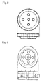
Fig. 2 is a diagram showing one example of the shape of a polishing pad. Grooves are formed to feed a polishing liquid from the center of the pad. Two identically shaped pads are prepared, and the two pads are combined for use. -
Fig. 3 is a diagram showing one example of a polishing pad. Bores are formed in the central portion of the pad to feed a polishing liquid. -
Fig. 4 is a diagram showing one example of the shape of a polishing pad. The pad ofFig. 2 is combined with the pad ofFig. 3 . -
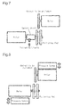
Fig. 5 is a diagram showing one example of a polishing device. -
Fig. 6 is a diagram showing one example of a polishing device. -
Fig. 7 is a diagram showing one example of a polishing device. This example is provided with a polishing liquid feeding unit. - Fig. & is a diagram showing one example of a polishing device. This example is provided with a pressure sensor or a device that functions in the same manner as the pressure sensor.
-
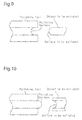
Fig. 9 is a partial side view showing a modified example of a polishing tool, which includes a polishing pad, and an object to be polished. -
Fig. 10 is a partial side view showing a modified example of a polishing tool, which includes a polishing pad, and an object to be polished. -
Fig. 11 is a partial side view showing a modified example of a polishing tool, which includes a polishing pad, and an object to be polished. -
Fig. 12 is a partial side view showing a modified example of a polishing tool, which includes a polishing pad, and an object to be polished. -
Fig. 13 is a partial side view showing one example of a polishing tool that is modified in shape -
Fig. 14 is a partial side view showing one example of a polishing tool that is modified in shape. - One embodiment of the present invention will now be described
- A polishing tool of the present embodiment has a feature in that the polishing tool is provided with a polishing pad including a polishing surface shaped in conformance with a curved surface of an object to be polished (workpiece to be polished) to uniformly contact the curved surface of the object (refer to
Fig. 1 ). The polishing tool of the present embodiment has a feature in that the polishing tool is shaped in conformance with a curved surface of an object to be polished to uniformly contact the curved surface of the object. - An object to be polished used in the present embodiment includes a curved surface. The curved surface of the object shows a curved line in a cross-section orthogonal to a surface to be polished of the object. Further, the shape of the curved line is identical or similar in the cross-section at a number of locations on the surface to be polished. A polishing tool including a polishing surface shaped in conformance with a curved surface of an object to be polished may be used to polish the object. This results in uniform contact of the curved surface of the object with the polishing surface of the polishing tool and allows for uniform polishing The curved line in the cross-section of the surface to be polished of the object may have any shape The curved line may be an arc or a combination of arcs and partially include a straight portion. For example, the curved surface of the object to be polished may be bulged toward the outer side of the object (refer to example shown in
Fig. 9 ) or recessed toward the inner side of the object (refer to example shown inFig. 10 ). Further, the object to be polished may include a surface to be polished having a generally triangular cross-section with a rounded peak (refer to example shown inFig. 11 ) or a generally stepped shape with rounded corners (refer to example shown inFig. 12 ). Even when the surface to be polished of the object to be polished is a curved surface having one of the above shapes, the use of a polishing tool including a polishing surface shaped in conformance with the curved surface of the object to polish the object results in uniform contact of the curved surface of the object with the polishing surface of the polishing tool and allows for uniform polishing. - The polishing tool of the present embodiment has a feature in that the polishing tool is provided with a polishing pad that includes a polishing surface shaped in conformance with a curved surface of an object to be polished. The polishing pad of the present embodiment need only be located on the edge or the periphery of the polishing tool The polishing pad may be adhered to the periphery of the polishing tool, coupled to the periphery of the polishing tool, or molded in any manner on the periphery of the polishing tool. Alternatively, the polishing tool may be molded as the polishing pad. There is no particular restriction to the material of the polishing tool except for the polishing portion (polishing pad), and a resin, a metal, or a ceramic may be used. Alternatively, a mixture of a plurality of materials may be used. For example, when a resin is used as the material of the polishing tool, any synthetic resin may be used. Examples of such a synthetic resin include a thermosetting resin (such as phenol resin, epoxy resin, urethane resin, and polyimide) and a thermoplastic resin (such as polyethylene, polypropylene, acrylic resin, polyamide, and polycarbonate). When a metal is used as the material of the polishing tool, magnesium, aluminum, titanium, iron, nickel, cobalt copper, zinc, manganese, or an alloy of which the main component is any of these metals may be used. When a ceramic is used as the material of the polishing tool, any of ceramics and glass; any of an oxide, nitride, boride, and carbide of silicon, aluminum, zirconium, calcium, and barium; or any of aluminum oxide, zirconium oxide, silicon oxide, silicon carbide, silicon nitride, and boron nitride may be used.
- Further, any material may be used for the object to be polished. For example, when using a resin, any synthetic resin may be used. Examples of such a synthetic resin include a thermosetting resin (such as phenol resin, epoxy resin, urethane resin, and polyimide) and a thermoplastic resin (such as polyethylene, polypropylene, acrylic resin, polyamide, and polycarbonate). When a ceramic is used as the material of the object to be polished, any of ceramics, glass, and fine ceramics; any of an oxide, carbide, nitride, and boride of silicon, aluminum, zirconium, calcium, and barium may be used. When a metal is used as the material of the object to be polished, magnesium, aluminum, titanium, iron, nickel, cobalt, copper, zinc, manganese, or an alloy of which the main component is any of these metals may be used. The object to be polished may be used for any purpose. For example, the object to be polished may be used as a wheel, a shaft, a container, a casing (for example, case and housing), a frame, a ball, a wire, an ornament, or the like
- It is preferred that the polishing tool be disk-shaped and have a diameter of 20 mm or larger. When the polishing tool has a large size, a high linear velocity is obtained even when the rotation speed is the same. Thus, there is no need for the rotation speed of the polishing tool to be high when performing polishing. Further, the centrifugal force applied to the polishing surface by the rotation can be reduced. This limits the dispersion of the polishing liquid. The size of the polishing tool is preferably 30 mm or larger in diameter, and more preferably 50 mm or larger in diameter.
- Further, the size of the polishing tool is preferably 1,000 mm in diameter or smaller, and more preferably 400 mm or smaller. When the diameter of the polishing tool is 1,000 mm and the rotation speed is 80 rpm, a linear velocity of 300 m/min is obtained. A polishing tool having a larger diameter obtains a higher linear velocity with a small rotation speed, further reduces the centrifugal force acting on the polishing surface, and limits the dispersion of the polishing liquid. When the size of the polishing tool is too large, the polishing device is enlarged and becomes noneconomic Thus, from an economic viewpoint, it is preferred that the size of the polishing tool be 1,000 mm or smaller in diameter.
- Depending on the polishing method or the specification of the polishing device, the polishing tool may be larger when, for example, the device polishes a plurality of objects with a single polishing tool. When a plurality of objects are polished at the same time, the processing efficiency increases, and the number of polishing devices required for polishing can be decreased.
- The polishing pad in the polishing tool of the present embodiment has a Shore A hardness of 5 or greater. When a polishing pad having a Shore A hardness of 5 or greater, which is subject to hardness measurement, is left for 60 minutes or longer in a dry condition where the humidity is 20% to 60% under room temperature, the hardness of the polishing pad is then measured with a durometer (type A) that is compliance with JIS K6253, and the measured value is 5 or greater. When the Shore A hardness of the polishing pad is 5 or greater, the surface of the object to be polished can be polished in a preferred manner. Further, deformation of the surface of the polishing pad can be reduced that would be caused by polishing performed within a short period of time.
- The polishing tool of the present embodiment has a feature in that the material of the polishing pad is at least one of a cloth, a non-woven fabric, a resin processed non-woven fabric, synthetic leather, synthetic resin foam, and a composite thereof. The polishing pad may include abrasive grains. When using a pad including abrasive grains, the type of the used abrasive grains is not particularly limited and may be metal oxide particles of silicon oxide, aluminum oxide, zirconium oxide, cerium oxide, magnesium oxide, calcium oxide, titanium oxide, manganese oxide, iron oxide, or chromium oxide; a carbide, such as silicon carbide; a nitride; a boride; or a diamond.
- The polishing method of the present embodiment is performed by using a polishing tool provided with a polishing pad including a polishing surface shaped in conformance with a curved surface of an object to be polished to uniformly contact the curved surface of the object, pressing the polishing pad against the curved surface of the object, and polishing the curved surface of the object by rotating the polishing tool while feeding a polishing liquid to a portion of contact between the polishing pad and the object.
- The polishing method of the present embodiment has a feature in that a polishing liquid is fed to the portion of contact between the polishing pad and the object to be polished. The polishing liquid may be fed by directly feeding the polishing liquid to the portion of contact from the outer side. Depending on the structure of the polishing device, for example, a polishing liquid feeding mechanism such as a rotary joint may be arranged at a connection portion of the polishing tool to directly feed a polishing liquid (processing liquid) to the polishing portion from the inside of the polishing tool (refer to
Figs. 2 to 4 and7 ). The feeding efficiency of the polishing liquid can be further increased by feeding the polishing liquid from the inside. - To efficiently use the polishing liquid, it is further preferable that a cover be arranged around the rotating polishing tool and that a recovery device be provided to increase the recovery efficiency of the polishing liquid.
- The polishing liquid may have a known composition used for polishing, lapping, or machining. The polishing liquid may be aqueous based, oil based, or ether based. Further, when necessary, an additive such as a pH adjuster, an etching agent, an oxidant, a complexing agent, a surfactant, an emulsifier, an antioxidant, an anticorrosive, a protective film forming agent, a thickener, a stabilizing agent, a dispersant, an antiseptic, and a fungicide may be used. Abrasive grains may further be added to the polishing liquid. The type of abrasive grains used for the polishing liquid is not particularly limited and may be metal oxide particles of silicon oxide, aluminum oxide, zirconium oxide, cerium oxide, magnesium oxide, calcium oxide, titanium oxide, manganese oxide, iron oxide, or chromium oxide; a carbide, such as silicon carbide; a nitride; a boride; or a diamond. Further, organic particles using, for example, thermoplastic resin may be used.
- It is preferred that the linear velocity during the polishing be 10 m/min or higher. When the linear velocity is 10m/min or higher, the edge of the object to be polished may be efficiently polished
- The rotation speed of the polishing tool during the polishing is preferably 5,000 rpm or lower, and more preferably 2,000 rpm or lower. When the polishing tool is rotated at a high speed of 5,000 rpm or higher, the centrifugal force acting on the polishing surface disperses the polishing liquid. Thus, to continue polishing, the polishing liquid needs to be replenished to make up for the dispersed amount. Thus, to hold the polishing liquid in the polishing tool in a suitable manner and perform stably polishing, the preferred rotation speed is 5,000 rpm or lower.
- The processing method of the present embodiment attaches a polishing tool to a certain polishing device to use the polishing tool. As long as the polishing device includes a mechanism that can hold and rotate the polishing tool, the polishing device is not particularly limited and may be, for example, a known polishing device. Examples of the polishing device include grinding devices such as a cylindrical grinder, a bench grinder, and a grinder. The relative positions of the polishing tool and the object to be polished need to be set so that the curved surface of the object can be polished. However, there may be any positional relationship. For example, the polishing tool may be supported horizontally (refer to
Fig. 6 ) or vertically (refer toFig. 5 ) and be pressed from any direction against the object to be polished to perform polishing In the polishing method of the present embodiment, a jig is used to fix the object to be polished at a certain angle and position. The jig is preferably movable and preferably able to sequentially perform polishing while moving the edge of the object to be polished. - The polishing method of the present embodiment is performed by attaching a polishing tool and/or an object to be polished to a polishing device that includes a pressure controller when polishing the object with the polishing tool, measuring the contact pressure at a portion of contact between a curved surface of the object and a surface of the polishing tool, and controlling the polishing pressure and the shape of the polishing portion in the polishing tool so that the contact pressure is uniform. To perform further uniform and accurate polishing, a pressure sensor or a device that functions in the same manner as the pressure sensor, namely, a pressure controller, is attached to the rotation shaft of the object to be polished, the rotation shaft of the polishing tool, or the polishing tool. The pressure at the portion of contact between the curved surface of the object to be polished and the polishing tool surface is measured and the distribution and change of the contact pressure are measured to control the polishing pressure and the shape of the polishing portion in the polishing tool during polishing. This keeps the polishing accuracy and the polishing efficiency constant and allows the timing for replacing the polishing tool to be checked (refer to
Fig. 8 ). -
Figs. 13 and 14 show a modified example of the present embodiment. In the modified example shown inFig. 13 , the polishingtool 10 includes a polishing pad formed from the material described above, more specifically, a material that elastically deforms and has a certain degree of elasticity. A polishingsurface 11 has a width H1 in a direction parallel to the rotation axis of the polishing tool 10 (direction of arrow Y inFig. 13 ) that is smaller by a predetermined amount a than the thickness T1 of the object to be polished K (i.e., distance between upper surface KU and lower surface KD of object to be polished K) prior to polishing. In this manner, the polishing pad is formed from an elastic body, and the polishingsurface 11 of the polishing pad is shaped to be smaller than the shape of the portion to be polished in the object K. This example has the advantages described below. - As shown in
Fig. 14 , in this modified example, when the polishingtool 10 is rotated and the object to be polished K is pressed against the polishingsurface 11, the polishing pad, which is elastically deformed by the predetermined amount α, applies a pressing force F to the upper surface KU and the lower surface KD of the object to be polished K. This is advantageous in that when polishing the object to be polished K, in addition to the edge KE, which has a curved surface, the upper surface KU and the lower surface KD are simultaneously polished. When the predetermined amount α is increased, the elastic deformation amount of the polishing pad increases when polishing the object to be polished K. Thus, the pressing force F applied to the upper surface KU and the lower surface KD of the object to be polished K may be optimized by optimizing the predetermined amount α. - The force for pressing the edge KE of the object to be polished K against the polishing
surface 11 and the pressing force F applied to the upper surface KU and the lower surface KD of the object to be polished K may be adjusted when necessary to properly polish the object K. - As described above, when molding the polishing tool as the polishing pad, the polishing
tool 10 is formed of a material like a resin that elastically deforms and has a certain degree of elasticity. Further, in the same manner as the modified example shown inFig. 13 , the width H1 of the polishingsurface 11 in thepolishing tool 10 is smaller by a predetermined amount α than the thickness T1 of the object to be polished K prior to polishing. In this manner, when the polishingtool 10, which functions as a polishing pad, is formed by an elastic body, and the polishingsurface 11 of the polishingtool 10 is shaped to be smaller than the portion to be polished in the object to be polished K, advantages similar to those of the modified example shown inFig. 13 can be obtained. - As described above, the present invention is effective as a polishing tool and a polishing method for accurately polishing a curved surface of an object to be polished. In particular, the present invention allows a curved surface of an object to be polished with high accuracy. Further, the present invention is more efficient than the conventional method.
- 10: polishing tool, 11: polishing surface, K: object to be polished, KE: edge (of object to be polished), KU: upper surface (of object to be polished), KD: lower surface (of object to be polished)
Claims (7)
- A polishing tool comprising a polishing pad including a polishing surface shaped in conformance with a curved surface of an object to be polished to uniformly contact the curved surface of the object.
- The polishing tool according to claim 1, wherein the polishing tool is disk-shaped and has a diameter of 20 mm or larger.
- The polishing tool according to claim 1 or 2, wherein the polishing pad has a Shore A hardness of 5 or greater
- A processing method comprising:by using a polishing tool provided with a polishing pad including a polishing surface shaped in conformance with a curved surface of an object to be polished to uniformly contact the curved surface of the object pressing the polishing pad against the curved surface of the object; andpolishing the curved surface of the object by rotating the polishing tool while feeding a polishing liquid to a portion of contact between the polishing pad and the object
- The processing method according to claim 4, wherein the polishing tool is disk-shaped and has a diameter of 20 mm or larger, the method further comprising controlling a rotation speed of the polishing tool and reducing centrifugal force acting on the polishing surface to reduce dispersion of the polishing liquid.
- The processing method according to claim 4 or 5, wherein the polishing pad has a surface including abrasive grains
- A method for polishing an object with a polishing tool, the method comprising:attaching the polishing tool and/or the object to be polished to a polishing device that includes a pressure controller;measuring a contact pressure at a portion of contact between a curved surface of the object and a surface of the polishing tool; andcontrolling a polishing pressure and a shape of a polishing portion in the polishing tool so that the contact pressure is uniform.
Applications Claiming Priority (2)
| Application Number | Priority Date | Filing Date | Title |
|---|---|---|---|
| JP2013167116 | 2013-08-09 | ||
| PCT/JP2014/070712 WO2015020082A1 (en) | 2013-08-09 | 2014-08-06 | Polishing tool and processing method for member |
Publications (2)
| Publication Number | Publication Date |
|---|---|
| EP3031577A1 true EP3031577A1 (en) | 2016-06-15 |
| EP3031577A4 EP3031577A4 (en) | 2017-03-22 |
Family
ID=52461413
Family Applications (1)
| Application Number | Title | Priority Date | Filing Date |
|---|---|---|---|
| EP14834968.1A Withdrawn EP3031577A4 (en) | 2013-08-09 | 2014-08-06 | Polishing tool and processing method for member |
Country Status (7)
| Country | Link |
|---|---|
| US (1) | US20160167192A1 (en) |
| EP (1) | EP3031577A4 (en) |
| JP (1) | JPWO2015020082A1 (en) |
| KR (1) | KR20160041908A (en) |
| CN (1) | CN105451938A (en) |
| TW (1) | TW201527048A (en) |
| WO (1) | WO2015020082A1 (en) |
Cited By (1)
| Publication number | Priority date | Publication date | Assignee | Title |
|---|---|---|---|---|
| CN106985059A (en) * | 2017-04-27 | 2017-07-28 | 厦门大学 | A kind of hollow ball inside and outside spherical surface polishing method and device |
Families Citing this family (5)
| Publication number | Priority date | Publication date | Assignee | Title |
|---|---|---|---|---|
| JP6292397B2 (en) * | 2014-04-23 | 2018-03-14 | 富士紡ホールディングス株式会社 | Polishing pad |
| JP6532884B2 (en) * | 2014-10-31 | 2019-06-19 | 株式会社荏原製作所 | Chemical mechanical polishing apparatus for polishing workpieces |
| KR102648921B1 (en) * | 2016-08-09 | 2024-03-19 | 삼성디스플레이 주식회사 | Imprint master template and method of manufacturing the same |
| JP6446590B1 (en) * | 2018-08-09 | 2018-12-26 | 国立大学法人 東京大学 | Local polishing method, local polishing apparatus, and corrected polishing apparatus using the local polishing apparatus |
| JP7093875B2 (en) * | 2021-06-24 | 2022-06-30 | 一郎 片山 | Workpiece processing equipment, grindstone, and work processing method |
Family Cites Families (23)
| Publication number | Priority date | Publication date | Assignee | Title |
|---|---|---|---|---|
| USRE25620E (en) * | 1964-07-21 | Polishing synthetic resin lenses | ||
| US1570177A (en) * | 1923-01-29 | 1926-01-19 | James B Pointer | Sanding block |
| US3144737A (en) * | 1962-09-27 | 1964-08-18 | Bausch & Lomb | Aluminum foil lens grinding pad |
| JPS5933587Y2 (en) * | 1980-12-09 | 1984-09-19 | 昭和ソキ−株式会社 | Grinding wheel for wire rods, etc. |
| JP2559650B2 (en) * | 1991-11-27 | 1996-12-04 | 信越半導体株式会社 | Wafer chamfer polishing device |
| US5662515A (en) * | 1993-12-15 | 1997-09-02 | Evensen; Kenneth | Method and apparatus for abrading with a profiled soft roller |
| JPH08267347A (en) * | 1995-03-31 | 1996-10-15 | Shin Etsu Handotai Co Ltd | Mirror surface polishing method of wafer chamfer with orientation flat |
| JPH11188590A (en) | 1997-12-22 | 1999-07-13 | Speedfam Co Ltd | Edge polishing device |
| JPH11320363A (en) * | 1998-05-18 | 1999-11-24 | Tokyo Seimitsu Co Ltd | Wafer chamfering equipment |
| JP2000061792A (en) * | 1998-08-14 | 2000-02-29 | Nikon Corp | Form grinding wheel |
| JP2001205549A (en) | 2000-01-25 | 2001-07-31 | Speedfam Co Ltd | One side polishing method and device for substrate edge portion |
| DE10004578C1 (en) * | 2000-02-03 | 2001-07-26 | Wacker Siltronic Halbleitermat | Production of a semiconductor wafer comprises polishing the edges of the wafer with a cloth with the continuous introduction of an alkaline polishing agent using polishing plates, wetting with a film and cleaning and drying |
| JP2004058186A (en) * | 2002-07-26 | 2004-02-26 | Hitachi Zosen Corp | Machining apparatus for outer circumferential part of thin sheet work |
| US8075372B2 (en) * | 2004-09-01 | 2011-12-13 | Cabot Microelectronics Corporation | Polishing pad with microporous regions |
| JP2007088143A (en) * | 2005-09-21 | 2007-04-05 | Elpida Memory Inc | Edge grinding device |
| EP2213415A1 (en) * | 2009-01-29 | 2010-08-04 | S.O.I. TEC Silicon | Device for polishing the edge of a semiconductor substrate |
| CN201366642Y (en) * | 2009-03-26 | 2009-12-23 | 常州工业技术玻璃有限公司 | Internal grinding wheel |
| WO2011105255A1 (en) * | 2010-02-26 | 2011-09-01 | 株式会社Sumco | Manufacturing method for semiconductor wafer |
| JP2012009550A (en) * | 2010-06-23 | 2012-01-12 | Disco Abrasive Syst Ltd | Wafer processing method |
| CN102441830A (en) * | 2011-11-24 | 2012-05-09 | 上海腾企机械技术配套有限公司 | Novel process and system for machining inner/outer curved surfaces by cut-in grinding/polishing |
| JP5982971B2 (en) * | 2012-04-10 | 2016-08-31 | 住友電気工業株式会社 | Silicon carbide single crystal substrate |
| CN103128627B (en) * | 2013-02-18 | 2016-06-08 | 洛阳轴研科技股份有限公司 | A kind of ball head pin bulb grinding processing method and device |
| JP2015196224A (en) * | 2014-04-01 | 2015-11-09 | 株式会社フジミインコーポレーテッド | Polishing method and retainer |
-
2014
- 2014-08-06 CN CN201480044902.3A patent/CN105451938A/en active Pending
- 2014-08-06 JP JP2015530920A patent/JPWO2015020082A1/en active Pending
- 2014-08-06 WO PCT/JP2014/070712 patent/WO2015020082A1/en not_active Ceased
- 2014-08-06 EP EP14834968.1A patent/EP3031577A4/en not_active Withdrawn
- 2014-08-06 KR KR1020167002949A patent/KR20160041908A/en not_active Withdrawn
- 2014-08-06 US US14/910,059 patent/US20160167192A1/en not_active Abandoned
- 2014-08-07 TW TW103127111A patent/TW201527048A/en unknown
Non-Patent Citations (1)
| Title |
|---|
| See references of WO2015020082A1 * |
Cited By (1)
| Publication number | Priority date | Publication date | Assignee | Title |
|---|---|---|---|---|
| CN106985059A (en) * | 2017-04-27 | 2017-07-28 | 厦门大学 | A kind of hollow ball inside and outside spherical surface polishing method and device |
Also Published As
| Publication number | Publication date |
|---|---|
| CN105451938A (en) | 2016-03-30 |
| US20160167192A1 (en) | 2016-06-16 |
| TW201527048A (en) | 2015-07-16 |
| JPWO2015020082A1 (en) | 2017-03-02 |
| EP3031577A4 (en) | 2017-03-22 |
| KR20160041908A (en) | 2016-04-18 |
| WO2015020082A1 (en) | 2015-02-12 |
Similar Documents
| Publication | Publication Date | Title |
|---|---|---|
| EP3031577A1 (en) | Polishing tool and processing method for member | |
| US11833704B2 (en) | Dynamic regulation of contact pressures in a blade sharpening system | |
| JP5406890B2 (en) | Method and trimming device for trimming two working layers | |
| TWI415709B (en) | A grinding method for the use of a spherical sphere of a bowl-shaped grinding wheel | |
| KR102252945B1 (en) | Surface grinding method for workpiece | |
| CA2717530C (en) | Orbital smoothing device | |
| KR20120085213A (en) | Method for providing a respective flat working layer on each of the two working disks of a double-side processing apparatus | |
| CN105658377A (en) | Polishing device and polishing method | |
| JP2831148B2 (en) | Abrasive body | |
| WO2015015706A1 (en) | Dressing method and dressing device | |
| CN104139336A (en) | A trimming tool | |
| KR20200001365A (en) | Retainer ring of chemical and mechanical polishing apparatus | |
| JP2016060031A (en) | Grinding wheel | |
| JP6631829B2 (en) | Flatness / flatness correction method for lapping machines and grinding wheels | |
| JP2019121650A (en) | Cmp device | |
| KR20160067107A (en) | Polishing device, processing method of polishing member, modification method of polishing member, shape processing cutting tool, and surface modification tool | |
| JP5959284B2 (en) | Curved surface polishing method and polishing apparatus | |
| CN107427985B (en) | Grinding method of diamond surface and device for implementing the same | |
| TWI590914B (en) | A chemical mechanical polishing dresser to adjust the height of the abrasive particles | |
| CN208557105U (en) | A kind of grinding mechanism | |
| KR102381100B1 (en) | Cutting grindstone with boron compound added | |
| JP2026015833A (en) | Dressing tools, how to use grinding stones, and grinding stones | |
| JP2007222969A (en) | Centerless grinding method | |
| EP3115152A2 (en) | Abrasive tool | |
| JP2023139462A (en) | Grinding wheels and grinding equipment |
Legal Events
| Date | Code | Title | Description |
|---|---|---|---|
| PUAI | Public reference made under article 153(3) epc to a published international application that has entered the european phase |
Free format text: ORIGINAL CODE: 0009012 |
|
| 17P | Request for examination filed |
Effective date: 20160202 |
|
| AK | Designated contracting states |
Kind code of ref document: A1 Designated state(s): AL AT BE BG CH CY CZ DE DK EE ES FI FR GB GR HR HU IE IS IT LI LT LU LV MC MK MT NL NO PL PT RO RS SE SI SK SM TR |
|
| AX | Request for extension of the european patent |
Extension state: BA ME |
|
| DAX | Request for extension of the european patent (deleted) | ||
| A4 | Supplementary search report drawn up and despatched |
Effective date: 20170220 |
|
| RIC1 | Information provided on ipc code assigned before grant |
Ipc: B24B 37/11 20120101ALI20170214BHEP Ipc: B24D 13/12 20060101ALI20170214BHEP Ipc: B24B 9/00 20060101AFI20170214BHEP Ipc: H01L 21/304 20060101ALI20170214BHEP |
|
| STAA | Information on the status of an ep patent application or granted ep patent |
Free format text: STATUS: THE APPLICATION HAS BEEN WITHDRAWN |
|
| 18W | Application withdrawn |
Effective date: 20180615 |