EP3031568A1 - Flux-cored wire for additional welding, and welding method - Google Patents
Flux-cored wire for additional welding, and welding method Download PDFInfo
- Publication number
- EP3031568A1 EP3031568A1 EP14834592.9A EP14834592A EP3031568A1 EP 3031568 A1 EP3031568 A1 EP 3031568A1 EP 14834592 A EP14834592 A EP 14834592A EP 3031568 A1 EP3031568 A1 EP 3031568A1
- Authority
- EP
- European Patent Office
- Prior art keywords
- mass
- welding
- flux
- wire
- less
- Prior art date
- Legal status (The legal status is an assumption and is not a legal conclusion. Google has not performed a legal analysis and makes no representation as to the accuracy of the status listed.)
- Withdrawn
Links
Images
Classifications
-
- B—PERFORMING OPERATIONS; TRANSPORTING
- B23—MACHINE TOOLS; METAL-WORKING NOT OTHERWISE PROVIDED FOR
- B23K—SOLDERING OR UNSOLDERING; WELDING; CLADDING OR PLATING BY SOLDERING OR WELDING; CUTTING BY APPLYING HEAT LOCALLY, e.g. FLAME CUTTING; WORKING BY LASER BEAM
- B23K35/00—Rods, electrodes, materials, or media, for use in soldering, welding, or cutting
- B23K35/22—Rods, electrodes, materials, or media, for use in soldering, welding, or cutting characterised by the composition or nature of the material
- B23K35/36—Selection of non-metallic compositions, e.g. coatings or fluxes; Selection of soldering or welding materials, conjoint with selection of non-metallic compositions, both selections being of interest
- B23K35/368—Selection of non-metallic compositions of core materials either alone or conjoint with selection of soldering or welding materials
-
- B—PERFORMING OPERATIONS; TRANSPORTING
- B23—MACHINE TOOLS; METAL-WORKING NOT OTHERWISE PROVIDED FOR
- B23K—SOLDERING OR UNSOLDERING; WELDING; CLADDING OR PLATING BY SOLDERING OR WELDING; CUTTING BY APPLYING HEAT LOCALLY, e.g. FLAME CUTTING; WORKING BY LASER BEAM
- B23K35/00—Rods, electrodes, materials, or media, for use in soldering, welding, or cutting
- B23K35/02—Rods, electrodes, materials, or media, for use in soldering, welding, or cutting characterised by mechanical features, e.g. shape
- B23K35/0255—Rods, electrodes, materials, or media, for use in soldering, welding, or cutting characterised by mechanical features, e.g. shape for use in welding
- B23K35/0261—Rods, electrodes or wires
- B23K35/0266—Rods, electrodes or wires flux-cored
-
- B—PERFORMING OPERATIONS; TRANSPORTING
- B23—MACHINE TOOLS; METAL-WORKING NOT OTHERWISE PROVIDED FOR
- B23K—SOLDERING OR UNSOLDERING; WELDING; CLADDING OR PLATING BY SOLDERING OR WELDING; CUTTING BY APPLYING HEAT LOCALLY, e.g. FLAME CUTTING; WORKING BY LASER BEAM
- B23K35/00—Rods, electrodes, materials, or media, for use in soldering, welding, or cutting
- B23K35/22—Rods, electrodes, materials, or media, for use in soldering, welding, or cutting characterised by the composition or nature of the material
- B23K35/24—Selection of soldering or welding materials proper
- B23K35/30—Selection of soldering or welding materials proper with the principal constituent melting at less than 1550°C
- B23K35/3053—Fe as the principal constituent
- B23K35/3073—Fe as the principal constituent with Mn as next major constituent
-
- B—PERFORMING OPERATIONS; TRANSPORTING
- B23—MACHINE TOOLS; METAL-WORKING NOT OTHERWISE PROVIDED FOR
- B23K—SOLDERING OR UNSOLDERING; WELDING; CLADDING OR PLATING BY SOLDERING OR WELDING; CUTTING BY APPLYING HEAT LOCALLY, e.g. FLAME CUTTING; WORKING BY LASER BEAM
- B23K35/00—Rods, electrodes, materials, or media, for use in soldering, welding, or cutting
- B23K35/40—Making wire or rods for soldering or welding
- B23K35/406—Filled tubular wire or rods
-
- C—CHEMISTRY; METALLURGY
- C21—METALLURGY OF IRON
- C21D—MODIFYING THE PHYSICAL STRUCTURE OF FERROUS METALS; GENERAL DEVICES FOR HEAT TREATMENT OF FERROUS OR NON-FERROUS METALS OR ALLOYS; MAKING METAL MALLEABLE, e.g. BY DECARBURISATION OR TEMPERING
- C21D9/00—Heat treatment, e.g. annealing, hardening, quenching or tempering, adapted for particular articles; Furnaces therefor
- C21D9/46—Heat treatment, e.g. annealing, hardening, quenching or tempering, adapted for particular articles; Furnaces therefor for sheet metals
-
- C—CHEMISTRY; METALLURGY
- C21—METALLURGY OF IRON
- C21D—MODIFYING THE PHYSICAL STRUCTURE OF FERROUS METALS; GENERAL DEVICES FOR HEAT TREATMENT OF FERROUS OR NON-FERROUS METALS OR ALLOYS; MAKING METAL MALLEABLE, e.g. BY DECARBURISATION OR TEMPERING
- C21D9/00—Heat treatment, e.g. annealing, hardening, quenching or tempering, adapted for particular articles; Furnaces therefor
- C21D9/52—Heat treatment, e.g. annealing, hardening, quenching or tempering, adapted for particular articles; Furnaces therefor for wires; for strips ; for rods of unlimited length
- C21D9/525—Heat treatment, e.g. annealing, hardening, quenching or tempering, adapted for particular articles; Furnaces therefor for wires; for strips ; for rods of unlimited length for wire, for rods
-
- C—CHEMISTRY; METALLURGY
- C22—METALLURGY; FERROUS OR NON-FERROUS ALLOYS; TREATMENT OF ALLOYS OR NON-FERROUS METALS
- C22C—ALLOYS
- C22C38/00—Ferrous alloys, e.g. steel alloys
- C22C38/02—Ferrous alloys, e.g. steel alloys containing silicon
-
- C—CHEMISTRY; METALLURGY
- C22—METALLURGY; FERROUS OR NON-FERROUS ALLOYS; TREATMENT OF ALLOYS OR NON-FERROUS METALS
- C22C—ALLOYS
- C22C38/00—Ferrous alloys, e.g. steel alloys
- C22C38/04—Ferrous alloys, e.g. steel alloys containing manganese
-
- C—CHEMISTRY; METALLURGY
- C22—METALLURGY; FERROUS OR NON-FERROUS ALLOYS; TREATMENT OF ALLOYS OR NON-FERROUS METALS
- C22C—ALLOYS
- C22C38/00—Ferrous alloys, e.g. steel alloys
- C22C38/06—Ferrous alloys, e.g. steel alloys containing aluminium
-
- C—CHEMISTRY; METALLURGY
- C22—METALLURGY; FERROUS OR NON-FERROUS ALLOYS; TREATMENT OF ALLOYS OR NON-FERROUS METALS
- C22C—ALLOYS
- C22C38/00—Ferrous alloys, e.g. steel alloys
- C22C38/18—Ferrous alloys, e.g. steel alloys containing chromium
- C22C38/40—Ferrous alloys, e.g. steel alloys containing chromium with nickel
- C22C38/58—Ferrous alloys, e.g. steel alloys containing chromium with nickel with more than 1.5% by weight of manganese
Definitions
- the present invention relates to a flux-cored wire for additional welding at a weld metal toe of main welding and a welding method. More specifically, the present invention relates to a flux-cored wire for additional welding, the wire having a configuration of a steel sheath filled with flux, and a welding method for performing additional welding with the wire.
- additional beads are sometimes formed at weld toes of main welding for the purpose of, for example, enhancement of fatigue strength of weld joints and reduction of residual stress (refer to Patent Literatures 1 to 3).
- welding materials used for such welding for forming additional beads in general, materials that have the same compositions as in main welding are used.
- Patent Literature 1 discloses that additional welding is performed to form a weld metal having a Ni content of 4 to 12 mass% and a Cr content of 7 to 15 mass%.
- Patent Literature 2 describes a welding method in which, for a weld metal formed by additional welding, the C, Cr, Ni, Si, Mn, Mo, and Nb contents are specified and the Ni and Cr contents are increased, so that the martensitic transformation starting temperature is adjusted to be 120°C to 400°C.
- Patent Literature 3 proposes a welding material for additional welding, the welding material having contents of C: 0.20 mass% or less, Cr: 5.0 to 18.0 mass%, and Ni: 3.0 to 15.0 mass%, the remainder being Fe and unavoidable impurities.
- Such existing welding materials for additional welding and weld metals formed of the welding materials in Patent Literatures 1 to 3 can provide the effects of enhancement of fatigue strength and reduction of residual stress.
- the weld metals excessively harden and have low cracking resistance and low toughness, which is problematic.
- Cr and Ni are expensive and addition of large amounts of Cr and Ni results in an increase in the production cost, which is also problematic. For these reasons, there has been a demand for a welding material for additional welding in which the amounts of Cr and Ni added are reduced.
- a main object of the present invention is to provide a flux-cored wire and a welding method in which, in additional welding, the fatigue strength of the weld can be enhanced while sufficiently high cracking resistance of the weld metal is ensured.
- the inventors of the present invention thoroughly performed experiments and studies. As a result, the inventors have found that a welding material having a high Mn content allows reduction in the amounts of Cr and Ni added, sufficiently high cracking resistance and toughness of the weld metal in additional welding, and enhancement of the fatigue strength of the weld. Thus, the inventors have accomplished the present invention.
- a flux-cored wire for additional welding includes a steel sheath filled with flux, wherein, relative to a total mass of the wire, the wire contains Si: 0.2 to 1.0 mass% and Mn: 3.0 to 10.0 mass%, contents are restricted as below, C: 0.1 mass% or less, P: 0.03 mass% or less, S: 0.03 mass% or less, and Cr and/or Ni: 3.8 mass% or less in total, and the wire is used for additional welding at a weld metal toe of main welding.
- the flux-cored wire according to the present invention may contain, relative to the total mass of the wire, Ni: 0.5 to 3.8 mass% and Mn: 3 to 7 mass%.
- the wire may have a composition that satisfies Formula 1 below where, relative to the total mass of the wire, the Mn content (mass%) is represented by [Mn] and the Ni content (mass%) is represented by [Ni].
- the Cr content relative to the total mass of the wire may be 1.0 mass% or less.
- the flux-cored wire according to the present invention may further contain, relative to the total mass of the wire, Al: 0.1 to 0.5 mass%. 3 ⁇ Mn + 0.5 ⁇ Ni ⁇ 6
- the present invention provides a welding method for performing additional welding, with the above-described flux-cored wire for additional welding, at a weld metal toe of main welding, the weld metal toe being made of a steel at least containing Mn: 0.5 to 2.0 mass% and Ni: 3.5 mass% or less (exclusive of 0).
- the additional welding may be performed by, for example, gas-shielded arc welding using a shielding gas containing 10 vol% or more of CO 2 .
- a specific amount of Mn is contained.
- the fatigue strength of the weld can be enhanced while sufficiently high cracking resistance of the weld metal is ensured.
- a flux-cored wire is a steel sheath filled with flux and the wire contains, relative to the total mass of the wire, 0.2 to 1.0 mass% of Si and 3.0 to 10.0 mass% of Mn. In addition, contents are restricted as follows: 0.1 mass% or less of C, 0.03 mass% or less of P, 0.03 mass% or less of S, and 3.8 mass% or less of Cr and/or Ni in total.
- a specific amount of Al can be added for the flux-cored wire according to the embodiment.
- the flux-cored wire according to the embodiment is not particularly limited in terms of outer diameter, and the outer diameter is, for example, 0.9 to 1.6 mm.
- the flux filling ratio can be set to a desired value as long as the components of the wire satisfy the above-described ranges.
- the flux filling ratio is preferably 8 to 25 mass% relative to the total mass of the wire from the standpoint of wire drawability and usability (such as feedability) during welding.
- Si exerts the effects of enhancing the strength of weld metals and smoothing the shape of bead toes to reduce stress concentration.
- Si content is less than 0.2 mass%, these effects are not sufficiently provided.
- Si content is more than 1.0 mass%, grain boundary segregation occurs, which tends to result in hot cracking. Accordingly, the Si content relative to the total mass of the wire is set to 0.2 to 1.0 mass%.
- Si source for the flux-cored wire includes Si contained in the steel sheath and Si sources contained in the flux that are Fe-Si, Fe-Si-Mn, Fe-Si-Mg, REM-Ca-Si, Fe-Si-B, SiO 2 ZrSiO 3 , K 2 SiF 6 , and MgSiO 3 .
- Mn exerts the effects of enhancing the hardenability, decreasing the martensitic transformation starting temperature (Ms point) of weld metals, and imparting compressive residual stress to weld metal toes. Also, an appropriate amount of Mn added exerts the effect of fixing S, which affects the hot cracking resistance of weld metals, as MnS to suppress hot cracking.
- MnS martensitic transformation starting temperature
- Mn source for the flux-cored wire examples include Mn contained in the steel sheath and Mn sources contained in the flux that are Fe-Mn, Si-Mn, and MnO 2 .
- C exerts the effects of enhancing the strength of weld metals, enhancing the hardenability, and decreasing the Ms point of weld metals.
- C is an element that tends to induce hot cracking. Specifically, when the C content is more than 0.1 mass%, hot cracking tends to occur in weld metals. Accordingly, the C content relative to the total mass of the wire is restricted to 0.1 mass% or less.
- P is also an element that tends to induce hot cracking.
- the P content is more than 0.03 mass%, hot cracking tends to occur in weld metals. Accordingly, the P content relative to the total mass of the wire is restricted to 0.03 mass% or less.
- S is, as with P above, an element that tends to induce hot cracking.
- S content is more than 0.03 mass%, hot cracking tends to occur in weld metals. Accordingly, the S content relative to the total mass of the wire is also restricted to 0.03 mass% or less.
- Cr exerts the effects of decreasing the Ms point of weld metals and enhancing the fatigue strength of welds.
- Cr-containing iron alloys form harder weld metals
- addition of a large amount of Cr causes the weld metals to excessively harden, resulting in low cracking resistance and low toughness.
- Ni also exerts the effect of decreasing the Ms point of weld metals. Addition of an appropriate amount of Ni can further enhance the fatigue strength of welds.
- addition of a large amount of Ni results in low cracking resistance and low toughness of weld metals.
- the total content of Cr and Ni relative to the total mass of the wire is more than 3.8 mass%, the weld metals have low cracking resistance and low toughness and intended characteristics are not obtained. Accordingly, when Cr and/or Ni is added for the flux-cored wire according to the embodiment, the total content of Cr and/or Ni is set to 3.8 mass% or less. As long as this range is satisfied, both of Cr and Ni may be contained; or, one of Cr and Ni may be contained; or, neither Cr nor Ni may be contained.
- the Cr content relative to the total mass of the wire is preferably restricted to 1.0 mass% or less.
- the Ni content is preferably set to 0.5 to 3.8 mass%, and the Mn content is preferably set to 3 to 7 mass%. This provides weld metals that are excellent in terms of both toughness and hot cracking resistance.
- the relationship between the Mn content and the Ni content preferably satisfies Formula 2 below.
- [Mn] represents the Mn content (mass%) relative to the total mass of the wire
- [Ni] represents the Ni content (mass%) relative to the total mass of the wire.
- the sum of the Mn content and 1/2 of the Ni content is set to be within the range of more than 3 and less than 6.
- Al exerts the effect of allowing uniform formation of slag over bead surfaces.
- Al causes a slight increase in the Ms point of weld metals.
- AI is added for the flux-cored wire according to the embodiment.
- the Al content is less than 0.1 mass%, the above-described effect due to addition is not provided.
- weld metals have low toughness and the increase in the Ms point results in low fatigue strength of welds.
- the AI content relative to the total mass of the wire is set to 0.1 to 0.5 mass%. As a result, slag can be uniformly formed over the whole surface of a welding bead.
- the remainder of the component composition of the flux-cored wire according to the embodiment is Fe and unavoidable impurities.
- the unavoidable impurities of the flux-cored wire according to the embodiment are, for example, Nb and V.
- the remainder of the flux-cored wire according to the embodiment contains O or N.
- Mo, Ti, Zr, Mg, K, Ca, Na, and F may be added.
- the flux-cored wire according to the embodiment is used for additional welding at a weld metal toe of main welding.
- the composition of the weld metal of the main weld is not particularly limited.
- the flux-cored wire according to the embodiment is particularly suitable when the weld metal of the main weld is a steel at least containing Mn: 0.5 to 2.0 mass% and Ni: 3.5 mass% or less (exclusive of 0). When the Mn content and the Ni content are within these ranges, reduction of the effects due to base material dilution is suppressed and a weld joint excellent in terms of cracking resistance and fatigue strength can be formed.
- the fatigue strength may be insufficient.
- the weld metal of the main weld has a Mn content of more than 2.0 mass%, the cracking resistance may lower.
- the weld metal of the main weld has a Ni content of more than 3.5 mass%, the cracking resistance of the weld metal may lower and the production cost is increased.
- the conditions for additional welding are not particularly limited. Normally, gas-shielded arc welding is performed.
- the shielding gas preferably contains 10 vol% or more of CO 2 and, more preferably, 100% CO 2 gas is used. Use of a shielding gas containing CO 2 allows suppression of incomplete fusion.
- the flux-cored wire according to the embodiment has a higher Mn content than the existing wires. As a result, even in spite of reduction of Ni and Cr contents, in additional welding, the fatigue strength of the weld can be enhanced while sufficiently high cracking resistance of the weld metal is ensured.
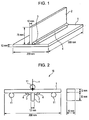
- Fig. 1 is a perspective view illustrating a double fillet weld joint used for evaluations.
- sheaths made of a steel having a composition described in Table 1 below were filled with flux to produce flux-cored wires of Examples and Comparative examples.
- Each wire was formed so as to have a diameter of 1.2 mm and a flux filling ratio of 12 to 18 mass% relative to the total mass of the wire.
- Composition (mass%) C Si Mn P S Remainder 0.016 0.01 0.19 0.005 0.005 Fe and unavoidable impurities
- base materials 1 and 2 having a composition described in Table 2 below were subjected to main welding at a welding current of 280 A and at a welding speed of 45 cm/min such that the lower leg length was 6 mm.
- additional welding was performed with each of the flux-cored wires of Examples and Comparative examples, with CO 2 (100%) serving as the shielding gas, at a welding current of 280 A, and at a welding speed of 45 cm/min such that the lower leg length was 12 mm.
- a double fillet weld joint illustrated in Fig. 1 was produced.
- Composition (mass%) C Si Mn P S Cr Ni Remainder 0.15 0.28 1.46 0.005 0.005 0.02 0.01 Fe and unavoidable impurities
- Fig. 2 is a side view illustrating a fatigue test method.
- the fatigue strength was evaluated by cutting out a test piece 10 illustrated in Fig. 2 from a double fillet weld joint illustrated in Fig. 1 and subjecting the test piece 10 to a three-point bending fatigue test under a partial fluctuating load.
- a 200 kN fatigue tester (PA24901) manufactured by TAKES GROUP LTD. was used.
- the test conditions were as follows: the ambient temperature was room temperature and the distance between fulcrums 11 was 150 mm; the load was controlled in accordance with a sine wave at a frequency of 15 Hz and at a stress ratio of 0.1 (partial fluctuating load).
- Arrow x in Fig. 2 indicates the direction in which the load was applied.
- test pieces having a fatigue strength of 300 MPa or more were evaluated as A (Excellent), test pieces having a fatigue strength of 250 MPa or more and less than 300 MPa were evaluated as B (Good), and test pieces having a fatigue strength of less than 250 MPa were evaluated as D (Poor).
- weld metals were subjected to a FISCO test according to JIS Z3155 and evaluated on the basis of the results. At this time, the welding current was set to 280 A and the welding speeds were set to 40, 50, and 70 cm/min. The thus-welded samples were subjected to an X-ray radiographic test. Samples that cracked even for 40 cm/min were evaluated as D (Poor); samples that did not crack only for 40 cm/min were evaluated as C (Fair); samples that did not crack for speeds of 50 cm/min or lower were evaluated as B (Good); and samples that did not crack even for 70 cm/min were evaluated as A (Excellent).
- Example Nos. 1 to 29 in which flux-cored wires produced so as to satisfy the ranges of the present invention were used provided good results for all evaluations of slag formation, fatigue strength of weld, toughness of weld metal, and cracking resistance.
- Example Nos. 25 to 27 in which flux-cored wires having an Al content of 0.1 to 0.5 mass% were used provided excellent results for all the items.
Landscapes
- Chemical & Material Sciences (AREA)
- Engineering & Computer Science (AREA)
- Mechanical Engineering (AREA)
- Materials Engineering (AREA)
- Metallurgy (AREA)
- Organic Chemistry (AREA)
- Physics & Mathematics (AREA)
- Thermal Sciences (AREA)
- Crystallography & Structural Chemistry (AREA)
- Nonmetallic Welding Materials (AREA)
- Plasma & Fusion (AREA)
- Arc Welding In General (AREA)
Abstract
Description
- The present invention relates to a flux-cored wire for additional welding at a weld metal toe of main welding and a welding method. More specifically, the present invention relates to a flux-cored wire for additional welding, the wire having a configuration of a steel sheath filled with flux, and a welding method for performing additional welding with the wire.
- In steel structures, additional beads are sometimes formed at weld toes of main welding for the purpose of, for example, enhancement of fatigue strength of weld joints and reduction of residual stress (refer to
Patent Literatures 1 to 3). As welding materials used for such welding for forming additional beads (additional welding), in general, materials that have the same compositions as in main welding are used. For example,Patent Literature 1 discloses that additional welding is performed to form a weld metal having a Ni content of 4 to 12 mass% and a Cr content of 7 to 15 mass%. -
Patent Literature 2 describes a welding method in which, for a weld metal formed by additional welding, the C, Cr, Ni, Si, Mn, Mo, and Nb contents are specified and the Ni and Cr contents are increased, so that the martensitic transformation starting temperature is adjusted to be 120°C to 400°C. Patent Literature 3 proposes a welding material for additional welding, the welding material having contents of C: 0.20 mass% or less, Cr: 5.0 to 18.0 mass%, and Ni: 3.0 to 15.0 mass%, the remainder being Fe and unavoidable impurities. -
- PTL 1:
Japanese Unexamined Patent Application Publication No. 2003-275890 - PTL 2:
Japanese Unexamined Patent Application Publication No. 2003-251489 - PTL 3:
Japanese Unexamined Patent Application Publication No. 2004-42133 - Such existing welding materials for additional welding and weld metals formed of the welding materials in
Patent Literatures 1 to 3 can provide the effects of enhancement of fatigue strength and reduction of residual stress. However, because of the high Cr and Ni contents, the weld metals excessively harden and have low cracking resistance and low toughness, which is problematic. In addition, Cr and Ni are expensive and addition of large amounts of Cr and Ni results in an increase in the production cost, which is also problematic. For these reasons, there has been a demand for a welding material for additional welding in which the amounts of Cr and Ni added are reduced. - Accordingly, a main object of the present invention is to provide a flux-cored wire and a welding method in which, in additional welding, the fatigue strength of the weld can be enhanced while sufficiently high cracking resistance of the weld metal is ensured.
- In order to achieve the object, the inventors of the present invention thoroughly performed experiments and studies. As a result, the inventors have found that a welding material having a high Mn content allows reduction in the amounts of Cr and Ni added, sufficiently high cracking resistance and toughness of the weld metal in additional welding, and enhancement of the fatigue strength of the weld. Thus, the inventors have accomplished the present invention.
- Specifically, a flux-cored wire for additional welding according to the present invention includes a steel sheath filled with flux, wherein, relative to a total mass of the wire, the wire contains Si: 0.2 to 1.0 mass% and Mn: 3.0 to 10.0 mass%, contents are restricted as below, C: 0.1 mass% or less, P: 0.03 mass% or less, S: 0.03 mass% or less, and Cr and/or Ni: 3.8 mass% or less in total, and the wire is used for additional welding at a weld metal toe of main welding. The flux-cored wire according to the present invention may contain, relative to the total mass of the wire, Ni: 0.5 to 3.8 mass% and Mn: 3 to 7 mass%.
- The wire may have a composition that satisfies
Formula 1 below where, relative to the total mass of the wire, the Mn content (mass%) is represented by [Mn] and the Ni content (mass%) is represented by [Ni]. - The Cr content relative to the total mass of the wire may be 1.0 mass% or less.
- The flux-cored wire according to the present invention may further contain, relative to the total mass of the wire, Al: 0.1 to 0.5 mass%.

- The present invention provides a welding method for performing additional welding, with the above-described flux-cored wire for additional welding, at a weld metal toe of main welding, the weld metal toe being made of a steel at least containing Mn: 0.5 to 2.0 mass% and Ni: 3.5 mass% or less (exclusive of 0).
- In the welding method according to the present invention, the additional welding may be performed by, for example, gas-shielded arc welding using a shielding gas containing 10 vol% or more of CO2.
- According to the present invention, a specific amount of Mn is contained. As a result, without addition of large amounts of Ni and Cr, in additional welding, the fatigue strength of the weld can be enhanced while sufficiently high cracking resistance of the weld metal is ensured.
-
- [
Fig. 1] Fig. 1 is a perspective view illustrating a double fillet weld joint used in Examples. - [
Fig. 2] Fig. 2 is a side view illustrating a fatigue test method. - Hereinafter, embodiments for carrying out the present invention will be described in detail. However, the present invention is not limited to the embodiments described below.
- A flux-cored wire according to an embodiment is a steel sheath filled with flux and the wire contains, relative to the total mass of the wire, 0.2 to 1.0 mass% of Si and 3.0 to 10.0 mass% of Mn. In addition, contents are restricted as follows: 0.1 mass% or less of C, 0.03 mass% or less of P, 0.03 mass% or less of S, and 3.8 mass% or less of Cr and/or Ni in total. For the flux-cored wire according to the embodiment, in addition to the above-described components, a specific amount of Al can be added.
- The flux-cored wire according to the embodiment is not particularly limited in terms of outer diameter, and the outer diameter is, for example, 0.9 to 1.6 mm. The flux filling ratio can be set to a desired value as long as the components of the wire satisfy the above-described ranges. The flux filling ratio is preferably 8 to 25 mass% relative to the total mass of the wire from the standpoint of wire drawability and usability (such as feedability) during welding.
- Hereafter, the reasons for placing numerical limitations on components of the flux-cored wire according to the embodiment will be described.
- Si exerts the effects of enhancing the strength of weld metals and smoothing the shape of bead toes to reduce stress concentration. However, when the Si content is less than 0.2 mass%, these effects are not sufficiently provided. On the other hand, when the Si content is more than 1.0 mass%, grain boundary segregation occurs, which tends to result in hot cracking. Accordingly, the Si content relative to the total mass of the wire is set to 0.2 to 1.0 mass%.
- Specific examples of the Si source for the flux-cored wire according to the embodiment include Si contained in the steel sheath and Si sources contained in the flux that are Fe-Si, Fe-Si-Mn, Fe-Si-Mg, REM-Ca-Si, Fe-Si-B, SiO2 ZrSiO3, K2SiF6, and MgSiO3.
- Mn exerts the effects of enhancing the hardenability, decreasing the martensitic transformation starting temperature (Ms point) of weld metals, and imparting compressive residual stress to weld metal toes. Also, an appropriate amount of Mn added exerts the effect of fixing S, which affects the hot cracking resistance of weld metals, as MnS to suppress hot cracking. However, when the Mn content is less than 3 mass%, the effects are not sufficiently provided. When the Mn content is more than 10 mass%, the weld metal excessively hardens, which tends to result in occurrence of hot cracking and causes a decrease in the toughness. Accordingly, the Mn content relative to the total mass of the wire is set to 3 to 10 mass%.
- Specific examples of the Mn source for the flux-cored wire according to the embodiment include Mn contained in the steel sheath and Mn sources contained in the flux that are Fe-Mn, Si-Mn, and MnO2.
- C exerts the effects of enhancing the strength of weld metals, enhancing the hardenability, and decreasing the Ms point of weld metals. However, C is an element that tends to induce hot cracking. Specifically, when the C content is more than 0.1 mass%, hot cracking tends to occur in weld metals. Accordingly, the C content relative to the total mass of the wire is restricted to 0.1 mass% or less.
- P is also an element that tends to induce hot cracking. When the P content is more than 0.03 mass%, hot cracking tends to occur in weld metals. Accordingly, the P content relative to the total mass of the wire is restricted to 0.03 mass% or less.
- S is, as with P above, an element that tends to induce hot cracking. When the S content is more than 0.03 mass%, hot cracking tends to occur in weld metals. Accordingly, the S content relative to the total mass of the wire is also restricted to 0.03 mass% or less.
- Cr exerts the effects of decreasing the Ms point of weld metals and enhancing the fatigue strength of welds. However, since Cr-containing iron alloys form harder weld metals, addition of a large amount of Cr causes the weld metals to excessively harden, resulting in low cracking resistance and low toughness. Similarly, Ni also exerts the effect of decreasing the Ms point of weld metals. Addition of an appropriate amount of Ni can further enhance the fatigue strength of welds. However, addition of a large amount of Ni results in low cracking resistance and low toughness of weld metals.
- Specifically, when the total content of Cr and Ni relative to the total mass of the wire is more than 3.8 mass%, the weld metals have low cracking resistance and low toughness and intended characteristics are not obtained. Accordingly, when Cr and/or Ni is added for the flux-cored wire according to the embodiment, the total content of Cr and/or Ni is set to 3.8 mass% or less. As long as this range is satisfied, both of Cr and Ni may be contained; or, one of Cr and Ni may be contained; or, neither Cr nor Ni may be contained.
- Compared with the case of adding Ni, addition of Cr tends to result in low cracking resistance and low toughness of weld metals. Accordingly, the Cr content relative to the total mass of the wire is preferably restricted to 1.0 mass% or less.
- On the other hand, when Ni is deliberately added, the Ni content is preferably set to 0.5 to 3.8 mass%, and the Mn content is preferably set to 3 to 7 mass%. This provides weld metals that are excellent in terms of both toughness and hot cracking resistance.
- Also, when Ni is deliberately added, the relationship between the Mn content and the Ni content preferably satisfies
Formula 2 below. InFormula 2 below, [Mn] represents the Mn content (mass%) relative to the total mass of the wire and [Ni] represents the Ni content (mass%) relative to the total mass of the wire. As indicated byFormula 2 below, the sum of the Mn content and 1/2 of the Ni content is set to be within the range of more than 3 and less than 6. As a result, weld metals excellent in terms of hot cracking resistance can be obtained even by high-current and high-speed welding while sufficiently high toughness of weld metals is ensured.
- Al exerts the effect of allowing uniform formation of slag over bead surfaces. However, Al causes a slight increase in the Ms point of weld metals. Accordingly, as needed, AI is added for the flux-cored wire according to the embodiment. In this case, when the Al content is less than 0.1 mass%, the above-described effect due to addition is not provided. When the Al content is more than 0.5 mass%, weld metals have low toughness and the increase in the Ms point results in low fatigue strength of welds. Accordingly, when Al is added, the AI content relative to the total mass of the wire is set to 0.1 to 0.5 mass%. As a result, slag can be uniformly formed over the whole surface of a welding bead.
- The remainder of the component composition of the flux-cored wire according to the embodiment is Fe and unavoidable impurities. The unavoidable impurities of the flux-cored wire according to the embodiment are, for example, Nb and V. When the above-described elements are added as oxides or nitrides, the remainder of the flux-cored wire according to the embodiment contains O or N. For the flux-cored wire according to the embodiment, in addition to the above-described components, for example, Mo, Ti, Zr, Mg, K, Ca, Na, and F may be added.
- The flux-cored wire according to the embodiment is used for additional welding at a weld metal toe of main welding. In this case, the composition of the weld metal of the main weld is not particularly limited. However, the flux-cored wire according to the embodiment is particularly suitable when the weld metal of the main weld is a steel at least containing Mn: 0.5 to 2.0 mass% and Ni: 3.5 mass% or less (exclusive of 0). When the Mn content and the Ni content are within these ranges, reduction of the effects due to base material dilution is suppressed and a weld joint excellent in terms of cracking resistance and fatigue strength can be formed.
- When the weld metal of the main weld has a Mn content of less than 0.5 mass% or a Ni content of 0 mass%, the fatigue strength may be insufficient. When the weld metal of the main weld has a Mn content of more than 2.0 mass%, the cracking resistance may lower. When the weld metal of the main weld has a Ni content of more than 3.5 mass%, the cracking resistance of the weld metal may lower and the production cost is increased.
- The conditions for additional welding are not particularly limited. Normally, gas-shielded arc welding is performed. In this case, the shielding gas preferably contains 10 vol% or more of CO2 and, more preferably, 100% CO2 gas is used. Use of a shielding gas containing CO2 allows suppression of incomplete fusion.
- As has been described in detail, the flux-cored wire according to the embodiment has a higher Mn content than the existing wires. As a result, even in spite of reduction of Ni and Cr contents, in additional welding, the fatigue strength of the weld can be enhanced while sufficiently high cracking resistance of the weld metal is ensured.
- Hereinafter, advantages of the present invention will be specifically described with reference to Examples according to the present invention and Comparative examples.
Fig. 1 is a perspective view illustrating a double fillet weld joint used for evaluations. In EXAMPLES, sheaths made of a steel having a composition described in Table 1 below, were filled with flux to produce flux-cored wires of Examples and Comparative examples. Each wire was formed so as to have a diameter of 1.2 mm and a flux filling ratio of 12 to 18 mass% relative to the total mass of the wire.[Table 1] Composition (mass%) C Si Mn P S Remainder 0.016 0.01 0.19 0.005 0.005 Fe and unavoidable impurities - Subsequently,
base materials weld metals 3 of the main welding, additional welding was performed with each of the flux-cored wires of Examples and Comparative examples, with CO2 (100%) serving as the shielding gas, at a welding current of 280 A, and at a welding speed of 45 cm/min such that the lower leg length was 12 mm. Thus, a double fillet weld joint illustrated inFig. 1 was produced.[Table 2] Composition (mass%) C Si Mn P S Cr Ni Remainder 0.15 0.28 1.46 0.005 0.005 0.02 0.01 Fe and unavoidable impurities - Each of the produced joints was visually observed for the state of slag on the surfaces of
weld metals 4 of the additional welding. On the basis of the results, joints in which the surfaces of theweld metals 4 of additional welding took on a uniform color were evaluated as A and joints in which the surfaces of theweld metals 4 of additional welding took on an uneven color were evaluated as B. -
Fig. 2 is a side view illustrating a fatigue test method. The fatigue strength was evaluated by cutting out atest piece 10 illustrated inFig. 2 from a double fillet weld joint illustrated inFig. 1 and subjecting thetest piece 10 to a three-point bending fatigue test under a partial fluctuating load. At this time, a 200 kN fatigue tester (PA24901) manufactured by TAKES GROUP LTD. was used. The test conditions were as follows: the ambient temperature was room temperature and the distance betweenfulcrums 11 was 150 mm; the load was controlled in accordance with a sine wave at a frequency of 15 Hz and at a stress ratio of 0.1 (partial fluctuating load). Arrow x inFig. 2 indicates the direction in which the load was applied. - The number of cycles was set to 500 thousand and the fatigue strength at 500 thousand cycles was determined as the fatigue strength. On the basis of the results, test pieces having a fatigue strength of 300 MPa or more were evaluated as A (Excellent), test pieces having a fatigue strength of 250 MPa or more and less than 300 MPa were evaluated as B (Good), and test pieces having a fatigue strength of less than 250 MPa were evaluated as D (Poor).
- For the cracking resistance of weld metals, weld metals were subjected to a FISCO test according to JIS Z3155 and evaluated on the basis of the results. At this time, the welding current was set to 280 A and the welding speeds were set to 40, 50, and 70 cm/min. The thus-welded samples were subjected to an X-ray radiographic test. Samples that cracked even for 40 cm/min were evaluated as D (Poor); samples that did not crack only for 40 cm/min were evaluated as C (Fair); samples that did not crack for speeds of 50 cm/min or lower were evaluated as B (Good); and samples that did not crack even for 70 cm/min were evaluated as A (Excellent).
- For the toughness of all-weld metal, an all-weld metal impact test at 0°C was performed in accordance with JIS Z3111 and, on the basis of the results, the samples were evaluated. Samples having an impact property of 60 J or more at 0°C were evaluated as A (Excellent), and samples having an impact property of 47 J or more and less than 60 J were evaluated as B (Good). Normally, the mechanical properties of weld joints are ensured by main welds thereof and hence additional welds are not required to have properties equivalent to those of main welds. Because an impact property of less than 47 J but 10 J or more at 0°C is on the practical level, in EXAMPLES, samples having an impact property of 10 J or more and less than 47 J were evaluated as C (Fair). Samples having an impact property of less than 10 J at 0°C were evaluated as D (Poor) because weld metals excessively harden and may crack during press straightening.
- The results are summarized in Table 3 and Table 4 below. The remainder of the wire composition of additional welding in Table 3 and Table 4 below is Fe and unavoidable impurities. Cr and Ni are often present as unavoidable impurities in steel sheaths. For example, Comparative example No. 39 in Table 4 has a Cr content of 0.07 mass% and Examples Nos. 21 and 22 have a Ni content of 0.03 mass%, which were added as impurities and were not deliberately added. Thus, the Cr content and the Ni content of wires for additional welding in Table 3 and Table 4 include Cr and Ni added as unavoidable impurities.
[Table 3] Wire composition (mass%) Weld metal of main welding (mass%) Evaluation results No. C Si Mn P S Cr Ni Al [Mn] + 0.5 × [Ni] Mn Ni Slag formation Fatigue strength Toughness vE0°C Cracking resistance 1 0.03 0.2 3.1 0.012 0.012 0.03 0.01 0.005 3.1 0.4 0.005 B B A A 2 0.01 0.9 3.0 0.013 0.013 0.05 0.01 0.007 3.0 0.2 0.006 B B A A 3 0.06 0.3 5.1 0.009 0.014 0.04 0.01 0.006 5.1 0.2 0.005 B B A A 4 0.07 1.0 5.3 0.015 0.012 0.02 0.01 0.006 5.3 0.3 0.005 B B A A 5 0.02 0.2 9.9 0.012 0.015 0.03 0.01 0.006 9.9 0.4 0.006 B B A C 6 0.09 1.0 10.0 0.011 0.013 0.04 0.01 0.006 10.0 0.3 0.006 B B A C. 7 0.04 0.3 4.5 0.013 0.012 0.05 0.30 0.005 4.7 0.4 0.005 B B A A 8 0.02 0.3 4.4 0.012 0.015 0.05 3.50 0.006 6.2 0.4 0.005 B A A B 9 0.01 0.2 5.2 0.013 0.013 0.05 0.01 0.1 5.2 0.4 0.005 A B A A 10 0.03 0.3 4.9 0.011 0.013 0.04 0.01 0.4 4.9 0.4 0.006 A B A A 11 0.01 0.2 6.5 0.011 0.01 0.03 0.01 0.005 6.5 0.5 0.005 B A B C Examples 12 0.02 0.2 4.0 0.014 0.007 0.05 0.01 0.006 4.0 2.0 0.007 B A A A 13 0.03 0.3 7.0 0.010 0.014 0.03 0.01 0.005 7.0 0.5 3.5 B A B C 14 0.04 0.3 4.0 0.008 0.014 0.05 0.01 0.005 4.0 2.0 3.5 B A A A 15 0.03 0.2 5.2 0.012 0.013 0.04 0.50 0.005 5.5 0.4 0.005 B A A A 16 0.03 0.2 9.7 0.014 0.015 0.03 1.50 0.006 10.5 0.3 0.006 B A A C 17 0.02 0.4 6.0 . 0.014 0.012 0.04 3.50 0,005 7.8 0.3 0.006 B A A B 18 0.03 0.3 4.3 0.013 0.012 0.33 1.00 0.006 4.8 0.3 0.005 B A A A 19 0.04 0.4 4.2 0.014 0.011 0.55 0.50 0.003 4.5 0.5 0.004 B A B A 20 0.03 0.5 4.5 0.013 0.011 0.95 0.03 0.003 4.5 0.4 0.005 B A B A 21 0.05 0.4 5.2 0.014 0.014 0.05 0.03 0.004 5.2 0.5 0.005 B B A A 22 0.04 0.4 6.5 0.015 0.01 0.04 0.50 0.1 6.8 0.3 0.006 A A A B 23 0.03 0.3 6.7 0.016 0.012 0.05 1.50 0.5 7.5 0.4 0.005 A A A B 24 0.05 0.3 5.3 0.012 0.011 0.03 3.50 0.3 7.1 0.3 0.006 A A A B [Table 4] Wire composition of additional welding (mass%) Weld metal of main welding (mass%) Evaluation results No. C Si Mn P S Cr Ni Al [Mn] + 0.5 × [Ni] Mn Ni Slag formation Fatigue strength Toughness vE0°C Cracking resistance 25 0.05 0.3 5.2 0.013 0.011 0.05 0.70 0.3 5.6 0.5 3.4 A A A A 26 0.05 0.2 3.5 0.013 0.011 0.05 1.00 0.3 4.0 0.5 2.5 A A A A Examples 27 0.04 0.3 4.5 0.012 0.012 0.06 1.30 0.2 5.2 0.7 1.5 A A A A 28 0.07 0.3 5.7 0.014 0.13 0.05 1.30 0.2 6.4 1.0 2.0 A A A B 29 0.05 0.3 5.7 0.015 0.012 0.04 3.70 0.2 7.6 1.9 0.5 A A A B 30 0.04 0.3 4.6 0.014 0.015 0.50 3.50 0.005 6.4 0.3 0.006 B A B D 31 0.05 0.4 7.0 0.013 0.015 0.05 4.50 0.006 9.3 0.4 0.005 B A B D 32 0.03 0.1 4.5 0.011 0.012 0.05 0.01 0.005 4.5 0.3 0.005 B D B B 33 0.05 1.2 7.0 0.012 0.011 0.03 0.01 0.006 7.0 0.4 0.005 B B B D 34 0.03 0.3 2.7 0.014 0.011 0.04 0.01 0.006 2.7 0.4 0.006 B D B B 35 0.05 0.2 10.3 0.011 0.012 0.05 0.01 0.005 10.3 0.3 0.005 B B C D 36 0.02 0.1 2.8 0.011 0.011 0.04 0.01 0.005 2.8 0.3 0.006 B D B B Comparative examples 37 0.03 1.2 10.2 0.012 0.015 0.05 0.01 0.006 10.2 0.4 0.005 B B C D 38 0.02 0.1 10.2 0.012 0.012 0.06 0.01 0.005 10.2 0.4 0.006 B B C D 39 0.03 1.1 2.8 0.011 0.015 0.07 0.01 0.005 2.8 0.4 0.005 B B B D 40 - - - - - - - - - 0.4 0.01 - D D - 41 - - - - - - - - - 0.7 1.5 - D - - 42 0.03 0.3 0.9 0.013 0.014 7.5 13.50 0.005 7.7 0.4 0.005 B B D D 43 0.04 0.3 1.3 0.012 0.014 8.0 2.50 0.005 2.6 0.4 0.005 B B D D 44 0.03 0.4 1.4 0.012 0.012 2.5 8.20 0.005 5.5 0.4 0.005 B B D D 45 0.04 0.3 1.5 0.140 0.012 10.5 12.30 - 7.7 0.4 0.005 B B D D - As described in Table 4 above, in Comparative examples Nos. 30 and 31 in which the total content of Cr and Ni was more than the range of the present invention, the weld metals had poor cracking resistance. In Comparative example No.32 in which the Si content was less than the range of the present invention and Comparative example No.34 in which the Mn content was less than the range of the present invention, the welds had poor fatigue strength. On the other hand, in Comparative example No.33 in which the Si content was more than the range of the present invention and Comparative example No.35 in which the Mn content was more than the range of the present invention, the weld metals had poor cracking resistance.
- In Comparative example No. 36 in which both of the Si content and the Mn content were less than the ranges of the present invention, the weld had poor fatigue strength. In Comparative example No. 37 in which both of the Si content and the Mn content were more than the ranges of the present invention and Comparative example No.38 in which the Si content was less than the range of the present invention and the Mn content was more than the range of the present invention, the weld metals had poor cracking resistance and the toughness was relatively low. On the other hand, in Comparative example No.39 in which the Si content was more than the range of the present invention and the Mn content was less than the range of the present invention, the weld metal had poor cracking resistance.
- In Comparative example Nos. 40 and 41 in which additional welding was not performed, the welds had poor fatigue strength. Comparative example Nos. 40 and 41 were not subjected to the other evaluations because additional welding was not performed. In Comparative example Nos. 42 to 45 in which additional welding was performed with existing flux-cored wires having high Cr and Ni contents, the weld metals had poor toughness and poor cracking resistance.
- In contrast, Example Nos. 1 to 29 in which flux-cored wires produced so as to satisfy the ranges of the present invention were used provided good results for all evaluations of slag formation, fatigue strength of weld, toughness of weld metal, and cracking resistance. In particular, Example Nos. 25 to 27 in which flux-cored wires having an Al content of 0.1 to 0.5 mass% were used provided excellent results for all the items.
- The results have demonstrated that, according to the present invention, in additional welding, the fatigue strength of the weld can be enhanced while sufficiently high cracking resistance of the weld metal is ensured.
-
- 1, 2 base material
- 3 weld metal of main welding
- 4 weld metal of additional welding
- 10 test piece
- 11 fulcrum
- x load application direction
Claims (7)
- A flux-cored wire for additional welding, the wire comprising a steel sheath filled with flux,
wherein, relative to a total mass of the wire,
the wire contains
Si: 0.2 to 1.0 mass% and
Mn: 3 to 10 mass%,
contents are restricted as below
C: 0.1 mass% or less,
P: 0.03 mass% or less,
S: 0.03 mass% or less, and
Cr and/or Ni: 3.8 mass% or less in total, and
the wire is used for additional welding at a weld metal toe of main welding. - The flux-cored wire for additional welding according to Claim 1, wherein the wire contains, relative to the total mass of the wire,
Ni: 0.5 to 3.8 mass%, and
Mn: 3 to 7 mass%. - The flux-cored wire for additional welding according to Claim 1 or 2, wherein the wire satisfies Formula (1) below where, relative to the total mass of the wire, the Mn content (mass%) is represented by [Mn] and the Ni content (mass%) is represented by [Ni].

- The flux-cored wire for additional welding according to Claim 1, wherein the Cr content relative to the total mass of the wire is 1.0 mass% or less.
- The flux-cored wire for additional welding according to Claim 1, wherein the wire further contains, relative to the total mass of the wire, Al: 0.1 to 0.5 mass%.
- A welding method for performing additional welding, with the flux-cored wire for additional welding according to any one of Claims 1 to 5,
at a weld metal toe of main welding, the weld metal toe being made of a steel at least containing Mn: 0.5 to 2.0 mass% and Ni: 3.5 mass% or less (exclusive of 0). - The welding method according to Claim 6, wherein the additional welding is gas-shielded arc welding using a shielding gas containing 10 vol% or more of CO2
Applications Claiming Priority (2)
| Application Number | Priority Date | Filing Date | Title |
|---|---|---|---|
| JP2013164606A JP6061809B2 (en) | 2013-08-07 | 2013-08-07 | Flux-cored wire for additional welding and welding method |
| PCT/JP2014/065251 WO2015019698A1 (en) | 2013-08-07 | 2014-06-09 | Flux-cored wire for additional welding, and welding method |
Publications (2)
| Publication Number | Publication Date |
|---|---|
| EP3031568A1 true EP3031568A1 (en) | 2016-06-15 |
| EP3031568A4 EP3031568A4 (en) | 2017-01-18 |
Family
ID=52461042
Family Applications (1)
| Application Number | Title | Priority Date | Filing Date |
|---|---|---|---|
| EP14834592.9A Withdrawn EP3031568A4 (en) | 2013-08-07 | 2014-06-09 | Flux-cored wire for additional welding, and welding method |
Country Status (5)
| Country | Link |
|---|---|
| EP (1) | EP3031568A4 (en) |
| JP (1) | JP6061809B2 (en) |
| KR (1) | KR101823798B1 (en) |
| CN (1) | CN105408053B (en) |
| WO (1) | WO2015019698A1 (en) |
Cited By (2)
| Publication number | Priority date | Publication date | Assignee | Title |
|---|---|---|---|---|
| EP3461581A1 (en) * | 2017-09-29 | 2019-04-03 | Lincoln Global, Inc. | Aluminum-containing welding electrode and its production method |
| US11529697B2 (en) | 2017-09-29 | 2022-12-20 | Lincoln Global, Inc. | Additive manufacturing using aluminum-containing wire |
Families Citing this family (4)
| Publication number | Priority date | Publication date | Assignee | Title |
|---|---|---|---|---|
| JP6740805B2 (en) * | 2016-08-23 | 2020-08-19 | 国立大学法人大阪大学 | Welding method, manufacturing method of welded joint, and welded joint |
| JP7606071B2 (en) * | 2020-10-07 | 2024-12-25 | 日本製鉄株式会社 | Manufacturing method of welded joint and flux-cored cut wire for filling groove |
| CN115106673B (en) * | 2021-03-22 | 2023-11-14 | 宝山钢铁股份有限公司 | Method for evaluating weldability of single-sided welding and double-sided forming of high-strength pipeline steel |
| CN115609175B (en) * | 2021-07-13 | 2026-03-17 | 宝山钢铁股份有限公司 | Fatigue behavior evaluation method for welded joints |
Family Cites Families (15)
| Publication number | Priority date | Publication date | Assignee | Title |
|---|---|---|---|---|
| US5233149A (en) * | 1991-08-02 | 1993-08-03 | Eaton Corporation | Reprocessing weld and method |
| US6336583B1 (en) * | 1999-03-23 | 2002-01-08 | Exxonmobil Upstream Research Company | Welding process and welded joints |
| JP2003251489A (en) | 2002-02-27 | 2003-09-09 | Jfe Steel Kk | Welded joint of low alloy steel material and its welding method |
| JP4733903B2 (en) | 2002-03-18 | 2011-07-27 | 新日本製鐵株式会社 | Fatigue life improving treatment method and long-life welded joint thereby |
| JP2004042133A (en) | 2002-05-15 | 2004-02-12 | Jfe Steel Kk | Welded joint excellent in stress corrosion cracking resistance and manufacturing method thereof |
| JP5179073B2 (en) * | 2007-03-08 | 2013-04-10 | 日鐵住金溶接工業株式会社 | Flux-cored wire for gas shielded arc welding |
| EP2289661B1 (en) * | 2009-08-27 | 2014-04-02 | Nippon Steel & Sumikin Welding Co., Ltd. | Flux cored wire for gas shielded arc welding of high strength steel |
| JP5459083B2 (en) * | 2010-06-04 | 2014-04-02 | 新日鐵住金株式会社 | Flux-cored wire for carbon dioxide shielded arc welding for high-tensile steel |
| JP5438663B2 (en) * | 2010-12-01 | 2014-03-12 | 株式会社神戸製鋼所 | Flux cored wire |
| JP5557790B2 (en) * | 2011-04-13 | 2014-07-23 | 日鐵住金溶接工業株式会社 | Flux-cored wire for 2-electrode horizontal fillet CO2 gas shielded arc welding |
| JP5768547B2 (en) * | 2011-07-08 | 2015-08-26 | 新日鐵住金株式会社 | High-strength steel flux cored wire for gas shielded arc welding |
| JP5726708B2 (en) * | 2011-10-26 | 2015-06-03 | 日鐵住金溶接工業株式会社 | Submerged arc welding method for low temperature steel |
| JP5894463B2 (en) * | 2012-02-27 | 2016-03-30 | 株式会社神戸製鋼所 | Method for forming weld metal with excellent resistance to hydrogen embrittlement |
| JP5704573B2 (en) * | 2012-04-25 | 2015-04-22 | 日鐵住金溶接工業株式会社 | Flux-cored wire for gas shielded arc welding of crude oil tank steel |
| JP5843164B2 (en) * | 2012-07-23 | 2016-01-13 | 株式会社神戸製鋼所 | Flux-cored wire for submerged arc welding |
-
2013
- 2013-08-07 JP JP2013164606A patent/JP6061809B2/en not_active Expired - Fee Related
-
2014
- 2014-06-09 WO PCT/JP2014/065251 patent/WO2015019698A1/en not_active Ceased
- 2014-06-09 EP EP14834592.9A patent/EP3031568A4/en not_active Withdrawn
- 2014-06-09 CN CN201480042456.2A patent/CN105408053B/en not_active Expired - Fee Related
- 2014-06-09 KR KR1020167003205A patent/KR101823798B1/en not_active Expired - Fee Related
Cited By (3)
| Publication number | Priority date | Publication date | Assignee | Title |
|---|---|---|---|---|
| EP3461581A1 (en) * | 2017-09-29 | 2019-04-03 | Lincoln Global, Inc. | Aluminum-containing welding electrode and its production method |
| US11426824B2 (en) | 2017-09-29 | 2022-08-30 | Lincoln Global, Inc. | Aluminum-containing welding electrode |
| US11529697B2 (en) | 2017-09-29 | 2022-12-20 | Lincoln Global, Inc. | Additive manufacturing using aluminum-containing wire |
Also Published As
| Publication number | Publication date |
|---|---|
| KR101823798B1 (en) | 2018-01-30 |
| EP3031568A4 (en) | 2017-01-18 |
| JP6061809B2 (en) | 2017-01-18 |
| CN105408053A (en) | 2016-03-16 |
| WO2015019698A1 (en) | 2015-02-12 |
| CN105408053B (en) | 2018-08-10 |
| KR20160028473A (en) | 2016-03-11 |
| JP2015033703A (en) | 2015-02-19 |
Similar Documents
| Publication | Publication Date | Title |
|---|---|---|
| EP3040153B1 (en) | Flux-cored wire | |
| EP3189930B1 (en) | Flux cored wire for gas-shielded arc welding | |
| KR101827193B1 (en) | Low-hydrogen type coated arc welding electrode | |
| JP7510049B2 (en) | Solid wire for gas shielded arc welding and method for manufacturing welded joint | |
| EP2674241A1 (en) | Weld metal with excellent creep characteristics | |
| KR101823798B1 (en) | Flux-cored wire for additional welding, and welding method | |
| JP6874425B2 (en) | Manufacturing method of flux-cored wire and welded joint for gas shielded arc welding | |
| NO20161607A1 (en) | Metallic flux-cored wire for Ar-CO2 mixed gas shielded ARC welding | |
| JP6265051B2 (en) | Flux-cored wire with excellent fatigue strength and cold cracking resistance of welded joints | |
| WO2018159719A1 (en) | Fillet welded joint and manufacturing method thereof | |
| KR102284226B1 (en) | Flux Cored Wire for Gas Shielded Arc Welding | |
| EP3208031B1 (en) | Flux-cored wire for gas shielded arc welding | |
| JP6939574B2 (en) | Flux-cored wire for gas shielded arc welding and welding joint manufacturing method | |
| JP6829111B2 (en) | Filling material for TIG welding | |
| EP2153932A1 (en) | Melt flux for submerged arc welding and method for submerged arc welding of steel for low temperature service | |
| EP3299486A1 (en) | Thick steel sheet and welded joint | |
| JP4676940B2 (en) | Manufacturing method of metal-based flux cored wire with low slag and high fatigue strength welded joint | |
| JP7376779B2 (en) | Welded joints and auto parts | |
| JP2017164768A (en) | HIGH Ni FLUX-CORED WIRE FOR GAS SHIELDED ARC WELDING AND METHOD OF MANUFACTURING WELDED JOINT | |
| JP4722811B2 (en) | Flux-cored wire for submerged arc welding for high-strength steel. | |
| JP4166752B2 (en) | Metal flux cored wire for high strength steel with excellent weldability | |
| KR100914796B1 (en) | Metallic flux cored wire, gas shielded arc welding process with the same, and process for production of welded joints having high fatigue strength with little slag | |
| KR102037658B1 (en) | Cladding and Clad Arc Welding Rods | |
| JP2020066750A (en) | Arc welding member |
Legal Events
| Date | Code | Title | Description |
|---|---|---|---|
| PUAI | Public reference made under article 153(3) epc to a published international application that has entered the european phase |
Free format text: ORIGINAL CODE: 0009012 |
|
| 17P | Request for examination filed |
Effective date: 20151223 |
|
| AK | Designated contracting states |
Kind code of ref document: A1 Designated state(s): AL AT BE BG CH CY CZ DE DK EE ES FI FR GB GR HR HU IE IS IT LI LT LU LV MC MK MT NL NO PL PT RO RS SE SI SK SM TR |
|
| AX | Request for extension of the european patent |
Extension state: BA ME |
|
| DAX | Request for extension of the european patent (deleted) | ||
| A4 | Supplementary search report drawn up and despatched |
Effective date: 20161215 |
|
| RIC1 | Information provided on ipc code assigned before grant |
Ipc: B23K 9/16 20060101ALI20161209BHEP Ipc: B23K 35/368 20060101ALI20161209BHEP Ipc: B23K 35/02 20060101ALI20161209BHEP Ipc: C22C 38/04 20060101ALI20161209BHEP Ipc: C22C 38/02 20060101ALI20161209BHEP Ipc: C22C 38/40 20060101ALI20161209BHEP Ipc: C22C 38/00 20060101ALI20161209BHEP Ipc: C22C 38/06 20060101ALI20161209BHEP Ipc: B23K 35/40 20060101ALI20161209BHEP Ipc: B23K 9/23 20060101ALI20161209BHEP Ipc: B23K 35/30 20060101AFI20161209BHEP Ipc: C21D 9/46 20060101ALI20161209BHEP Ipc: C22C 38/58 20060101ALI20161209BHEP Ipc: C21D 9/52 20060101ALI20161209BHEP |
|
| 17Q | First examination report despatched |
Effective date: 20190404 |
|
| STAA | Information on the status of an ep patent application or granted ep patent |
Free format text: STATUS: THE APPLICATION IS DEEMED TO BE WITHDRAWN |
|
| 18D | Application deemed to be withdrawn |
Effective date: 20190815 |