EP3031299B1 - Section de moyens d'éclairage à del à intensité variable - Google Patents
Section de moyens d'éclairage à del à intensité variable Download PDFInfo
- Publication number
- EP3031299B1 EP3031299B1 EP14745139.7A EP14745139A EP3031299B1 EP 3031299 B1 EP3031299 B1 EP 3031299B1 EP 14745139 A EP14745139 A EP 14745139A EP 3031299 B1 EP3031299 B1 EP 3031299B1
- Authority
- EP
- European Patent Office
- Prior art keywords
- lighting means
- lms
- led lighting
- led lamp
- control unit
- Prior art date
- Legal status (The legal status is an assumption and is not a legal conclusion. Google has not performed a legal analysis and makes no representation as to the accuracy of the status listed.)
- Active
Links
- 238000000034 method Methods 0.000 claims description 12
- 230000008859 change Effects 0.000 claims description 11
- 230000003213 activating effect Effects 0.000 claims description 6
- 239000011159 matrix material Substances 0.000 claims description 6
- 238000011144 upstream manufacturing Methods 0.000 claims description 4
- 230000008569 process Effects 0.000 description 6
- 238000011156 evaluation Methods 0.000 description 4
- 230000008054 signal transmission Effects 0.000 description 4
- 229910052736 halogen Inorganic materials 0.000 description 2
- 150000002367 halogens Chemical class 0.000 description 2
- 230000009467 reduction Effects 0.000 description 2
- 230000011664 signaling Effects 0.000 description 2
- 230000001960 triggered effect Effects 0.000 description 2
- 230000004913 activation Effects 0.000 description 1
- 230000005540 biological transmission Effects 0.000 description 1
- 238000004891 communication Methods 0.000 description 1
- 238000012937 correction Methods 0.000 description 1
- 230000009849 deactivation Effects 0.000 description 1
- 230000003247 decreasing effect Effects 0.000 description 1
- 230000001419 dependent effect Effects 0.000 description 1
- 238000013461 design Methods 0.000 description 1
- 238000011161 development Methods 0.000 description 1
- 230000018109 developmental process Effects 0.000 description 1
- 238000010586 diagram Methods 0.000 description 1
- 230000005611 electricity Effects 0.000 description 1
- 238000005516 engineering process Methods 0.000 description 1
- 238000009434 installation Methods 0.000 description 1
- 230000003287 optical effect Effects 0.000 description 1
- 230000001629 suppression Effects 0.000 description 1
- 230000001360 synchronised effect Effects 0.000 description 1
Images


Classifications
-
- H—ELECTRICITY
- H05—ELECTRIC TECHNIQUES NOT OTHERWISE PROVIDED FOR
- H05B—ELECTRIC HEATING; ELECTRIC LIGHT SOURCES NOT OTHERWISE PROVIDED FOR; CIRCUIT ARRANGEMENTS FOR ELECTRIC LIGHT SOURCES, IN GENERAL
- H05B45/00—Circuit arrangements for operating light-emitting diodes [LED]
- H05B45/40—Details of LED load circuits
- H05B45/44—Details of LED load circuits with an active control inside an LED matrix
- H05B45/48—Details of LED load circuits with an active control inside an LED matrix having LEDs organised in strings and incorporating parallel shunting devices
-
- H—ELECTRICITY
- H05—ELECTRIC TECHNIQUES NOT OTHERWISE PROVIDED FOR
- H05B—ELECTRIC HEATING; ELECTRIC LIGHT SOURCES NOT OTHERWISE PROVIDED FOR; CIRCUIT ARRANGEMENTS FOR ELECTRIC LIGHT SOURCES, IN GENERAL
- H05B45/00—Circuit arrangements for operating light-emitting diodes [LED]
- H05B45/10—Controlling the intensity of the light
-
- H—ELECTRICITY
- H05—ELECTRIC TECHNIQUES NOT OTHERWISE PROVIDED FOR
- H05B—ELECTRIC HEATING; ELECTRIC LIGHT SOURCES NOT OTHERWISE PROVIDED FOR; CIRCUIT ARRANGEMENTS FOR ELECTRIC LIGHT SOURCES, IN GENERAL
- H05B45/00—Circuit arrangements for operating light-emitting diodes [LED]
- H05B45/30—Driver circuits
- H05B45/37—Converter circuits
- H05B45/3725—Switched mode power supply [SMPS]
-
- H—ELECTRICITY
- H05—ELECTRIC TECHNIQUES NOT OTHERWISE PROVIDED FOR
- H05B—ELECTRIC HEATING; ELECTRIC LIGHT SOURCES NOT OTHERWISE PROVIDED FOR; CIRCUIT ARRANGEMENTS FOR ELECTRIC LIGHT SOURCES, IN GENERAL
- H05B45/00—Circuit arrangements for operating light-emitting diodes [LED]
- H05B45/40—Details of LED load circuits
- H05B45/44—Details of LED load circuits with an active control inside an LED matrix
- H05B45/46—Details of LED load circuits with an active control inside an LED matrix having LEDs disposed in parallel lines
-
- H—ELECTRICITY
- H05—ELECTRIC TECHNIQUES NOT OTHERWISE PROVIDED FOR
- H05B—ELECTRIC HEATING; ELECTRIC LIGHT SOURCES NOT OTHERWISE PROVIDED FOR; CIRCUIT ARRANGEMENTS FOR ELECTRIC LIGHT SOURCES, IN GENERAL
- H05B47/00—Circuit arrangements for operating light sources in general, i.e. where the type of light source is not relevant
- H05B47/10—Controlling the light source
- H05B47/175—Controlling the light source by remote control
- H05B47/185—Controlling the light source by remote control via power line carrier transmission
-
- Y—GENERAL TAGGING OF NEW TECHNOLOGICAL DEVELOPMENTS; GENERAL TAGGING OF CROSS-SECTIONAL TECHNOLOGIES SPANNING OVER SEVERAL SECTIONS OF THE IPC; TECHNICAL SUBJECTS COVERED BY FORMER USPC CROSS-REFERENCE ART COLLECTIONS [XRACs] AND DIGESTS
- Y02—TECHNOLOGIES OR APPLICATIONS FOR MITIGATION OR ADAPTATION AGAINST CLIMATE CHANGE
- Y02B—CLIMATE CHANGE MITIGATION TECHNOLOGIES RELATED TO BUILDINGS, e.g. HOUSING, HOUSE APPLIANCES OR RELATED END-USER APPLICATIONS
- Y02B20/00—Energy efficient lighting technologies, e.g. halogen lamps or gas discharge lamps
- Y02B20/30—Semiconductor lamps, e.g. solid state lamps [SSL] light emitting diodes [LED] or organic LED [OLED]
Definitions
- the invention relates to a dimmable LED lamp range.
- the dimmable LED lamp section has at least two parallel and / or counter-parallel LED lamp chains and a control unit.
- the LED illuminant chains are designed as LED chains and each LED illuminant chain has at least one illuminant as a light emitting diode, ie an LED.
- the invention further relates to a method for operating an LED lamp section, an LED lamp comprising an LED lamp section according to the invention, and a retrofit lamp comprising an LED lamp section according to the invention.
- a light-emitting diode (LED) is understood to mean both inorganic and organic light-emitting diodes.
- Retrofit lamps are to be understood in particular as retrofit LED lamps which use one or more LEDs as illuminants, but are designed for mechanical and electrical connection in such a way that they can be used as substitutes for other illuminants, such as, for example, incandescent or halogen lamps are.
- the publication WO 2010/027254 A1 discloses an LED based lighting application and the publication US 2010/0231135 A1 discloses a reconfigurable LED array and its use in a lighting system.
- the publication US 2012/0038284 A1 discloses a lighting device that can be dimmed and subjected to a change in color temperature of the lighting color in accordance with a dimming level.
- Retrofit lamps are equipped with screw, bayonet or plug-in bases that match the sockets developed for incandescent or halogen lamps. However, this mechanical adjustment alone is not sufficient for the replacement. Due to the different modes of operation of incandescent lamps (process AC half-waves with both polarities) on the one hand and light-emitting diodes (are only effective with AC half-waves of a certain polarity) on the other hand, additional measures are required. The latter particularly affect the type of dimming.
- a disadvantage of devices in which several identical LED chains are operated in direct connection with an alternating voltage that the brightness of the LED chains change their brightness synchronously with the alternating voltage and that the course of the alternating voltage is synchronized with a brightness modulation.
- a certain number of LEDs are selectively switched on or off for each of the parallel LED chains in synchronism with the course of the AC voltage.
- the object of the invention is now to provide a dimming technique which overcomes the disadvantages of the prior art.
- the invention provides a dimmable LED lamp range, a dimming method, an LED lamp and a retrofit lamp according to the independent claims. Further developments of the invention are the subject of the dependent claims.
- a dimmable LED lamp section is provided with at least two LED lamp chains connected in parallel and / or in parallel, each having a plurality of light-emitting diodes, the LED lamp section having a control unit and being supplied via a supply which is set up to supply dimming information via the supply to get supplied and depending on the supplied dimming information and for its implementation individual on / off parallel switching of the LED lamp chains connected in parallel or in parallel.
- Each light-emitting diode of the LED light source section can be bridged by at least one switching element which is provided in parallel and can be switched by the control unit.
- the control unit can activate or deactivate the switching elements, in particular as a function of an electrical supply to the LED lamp path.
- the LED lamp section can have LED lamp chains connected in parallel and can be operated directly from an AC voltage.
- the LED lamp section can have parallel LED lamp chains and can be operated directly from a DC voltage.
- the LED lamp range can have lamp chains connected in parallel, which are preceded by a rectifier, and can be operated directly from an AC voltage.
- the control unit is set up to activate or deactivate the switching elements depending on the electrical supply of the LED light source section individual light emitting diodes in the LED light source chains, which essentially share a coordinate in their spatial orientation in different LED light source chains, by activating or deactivating the switching elements. switch off.
- a converter can convert an AC voltage into a DC voltage and provide the DC voltage as an electrical supply for the LED lamp section.
- the converter can change an electrical supply supplied to the LED lamp section depending on dimming information.
- the converter can be, for example, a flyback converter (isolated flyback converter), a buck converter (buck converter) or an isolated half-bridge converter.
- the control unit can evaluate a signal transmitted by means of the supply voltage, for example a phase cut-off signal and / or a selective half-wave rectification, in order to detect the dimming information.
- a signal transmitted by means of the supply voltage for example a phase cut-off signal and / or a selective half-wave rectification
- the control unit can, in particular one, by evaluating the electrical supply to the LED lamp path Change in the electrical supply (for example the supply voltage), the dimming information.
- the electrical supply can be a direct voltage output by a converter.
- the dimming information can be an amplitude / change in amplitude of the electrical supply.
- the LED lamp section can have a rectifier and / or the drive converter.
- the light-emitting diodes and the switching elements for bridging are arranged in a matrix structure, wherein at least one light-emitting diode can be bridged in each row of LED lamps and in each LED lamp chain at least one switching element that can be switched by the control unit and is set up to set up the respective LED lamp chain is provided on or off.
- an LED lamp comprising an LED lamp section according to one of the preceding claims.
- a retrofit lamp comprising an LED lamp section according to one of the preceding claims.
- a method for controlling a dimmable LED lamp section with at least two LED lamp chains connected in parallel and / or in parallel wherein a control unit of the LED lamp section detects dimming information supplied via the supply and, depending on the recorded dimming information and for its implementation, gradually switches on and / or off individual LED lamp chains connected in parallel / in parallel, with each LED being connected by at least one in parallel provided and switchable by the control unit switching element can be bridged.
- dimming information is fed to a control unit at an input via the supply.
- the control unit now not only switches off individual LEDs in an LED lamp chain or LED chain, but can also, in particular, carry out step-by-step dimming by selectively switching complete LED lamp chains on or off.
- leading edge phase dimmers have largely established themselves for lighting systems with conventional incandescent lamps. This is particularly because they work largely lossless. However, the latter does not apply to operation with LEDs. In order to limit the power losses, a considerable additional circuit effort is required. In addition, leading-edge phase dimmers - even when operated with incandescent lamps - inevitably emit undesirable harmonics into the network. However, a largely sinusoidal current consumption is expected from modern modules. This can be achieved by the additional installation of actively clocked PFCs (power factor correction circuits).
- a signal can be transmitted to an electrical load supplied with AC voltage, in particular an LED lamp or retrofit lamp, in that at least the signal states "application of a phase signal / phase signal” and “non-signal of a phase signal / phase signal” or “rectified AC voltage” and “non-rectified, ie bipolar AC voltage” are present.
- any complex analog or digital can be created Implement signaling protocols.
- An evaluation by a control unit for example, of the duration and / or a repetition rate of the respective logical state is analogous.
- the two physical states mentioned can be used as logic "1" and "0" for digital signal transmission.
- This protocol can be addressed or unaddressed.
- data or signals can be part of the protocol.
- the communication technology mentioned by means of selective phase connection / phase connection or selective rectification does not fundamentally exclude that further logical states may exist on the AC supply line in addition to the two states mentioned. These can be, for example, PLC modulation (power line carrier, high-frequency modulation with a preferably low amplitude) or a temporary suppression of the AC voltage.
- Phase sections or phase gates can also be implemented in combination with selective rectification, and there are other possible combinations, such as additional amplitude modulation.
- Signal transmission to control unit 5 is therefore preferably carried out by selective phase gating or selective rectification of the AC supply voltage. If a return channel is to be present, this can be done by any other type of signaling (see the examples above).
- the light-emitting diodes (as the illuminant of the LED illuminant chains, that is to say the LEDs of the LED chains) are arranged in a matrix arrangement and a certain number of the light-emitting diodes can be bridged by switching elements provided in parallel with the light-emitting diodes. In particular, one switching element can be provided for each light-emitting diode.
- the dimming information which preferably represents a dimming value, can be determined by the control unit by evaluating the electrical supply supplied to the LED lamp section, in particular the supply voltage supplied to the LED lamp section.
- the control unit can, for example, evaluate a selective phase section or section or selective rectification of the supply voltage and then selectively switch on and / or off individual, several or all of the lamp strings by activating / deactivating the switching elements provided. Activation of a switching element is understood here to mean switching the switching element into the conductive state.
- a rectifier can be connected upstream of the LED lamp section, which converts the AC voltage into a DC voltage.
- the rectifier can be designed as a full-wave rectifier or as a one-way rectifier.
- the lamp chains are connected in anti-parallel or counter-parallel, so that the LED lamp section can be supplied directly from an AC voltage and thus the LED lamp section can also be operated appropriately with an AC voltage supply.
- the control unit acquires dimming information (a dimming signal) or determines this from the supply voltage supplied to it and gradually activates / deactivates the LED lamp chains of the LED lamp section.
- this switching on and off takes place by switching elements / bridging, or by switching off / connecting the supply paths to the LED lamp chains by means of the switching elements.
- the control unit can now operate individual LEDs in the LED lamp chains by activating / deactivating one or more corresponding switching elements switch on or off. This can be done selectively.
- control unit then deactivates or activates one or more LED lamp chains.
- the control unit can activate / deactivate individual light emitting diodes in the LED lamp chains, in particular when the LED lamp section is supplied from an AC voltage, depending on the detected voltage.
- light-emitting diodes along an axis of the matrix e.g. Essentially, light emitting diodes in an LED lamp row can be deactivated or activated.
- the preferably corresponding light-emitting diodes have the same coordinate in terms of their spatial orientation, or the same coordinate ratio (e.g. for diagonals).
- control unit can thus deactivate or activate one or more rows of LED lamps.
- AC AC voltage / current
- DC DC voltage / current
- the converter is a converter for converting AC voltage / current to DC voltage / current) so that the LED lamp chains of the LED lamp section are not operated with AC, but in particular with DC.
- the brightness modulation of the LED lamp path can thus be reduced.
- the AC / DC converter used can also be set up to evaluate a dimming control signal.
- a dimming control signal can be, for example, a digital bus signal that is supplied via a wired or wireless bus, a phase control signal, a phase control signal or a dimming control signal that results from the evaluation of the supply voltage half-waves supplied to the converter.
- the LED lamp section is controlled with DC voltage. Dimming information acquired and evaluated by the AC / DC converter can now be evaluated by the control unit in such a way that individual switching elements provided in the LED illuminant path are switched by the control unit, so that the dimming information recorded is preferably used for the selective complete switching on and off of individual / several / all LED lamp chains can be done.
- the dimming information which preferably reproduces a dimming value, can be obtained from the control unit by evaluating the electrical supply supplied by the AC / DC converter to the LED lamp section, in particular, from the AC / DC converter of the LED Bulb supply voltage supplied can be determined.
- the control unit can, for example, also evaluate an amplitude of the supply voltage and then selectively switch on and / or off individual, several or all of the lamp strings by activating / deactivating the switching elements provided.
- the supply voltage evaluated by the control unit can be a direct voltage output by the AC / DC converter.
- Fig. 1 shows an example of an LED lamp range LMS according to the invention.
- LED lamp chains LMK1, LMK2, LMK3 are operated.
- the LED lamp chains LMK1, LMK2, LMK3 are connected in parallel in the diagram shown and each have LED lamps L (ie a light emitting diode or LED).
- Switching elements S are connected in series and in parallel with the light-emitting diodes L.
- the switching elements S parallel to the light-emitting diodes L now serve, on the one hand, to bypass and thus deactivate individual light-emitting diodes L, while the switching elements S connected in series with the light-emitting diodes L can serve to decouple light-emitting diodes L from the respective LED lamp chain, or to interrupt the supply path of an LED lamp chain and thus to deactivate the LED lamp chain.
- Example are the bypass switching elements in parallel to the second LED lamp chain LMK2 in Fig. 1 designated US2.
- US1 designates the bridging switching elements of a first LED lamp chain LMK1 and US3 the bridging switching elements of a third LED lamp chain LMK3.
- individual light-emitting diodes L can be bridged and thus deactivated by the switching elements S parallel to the light-emitting diodes L, and in this way an LED lamp line (that is to say on the same level, quasi-parallel light-emitting diodes) can be bridged and thus deactivated.
- an LED lamp row for example, an LED lamp diagonal can also be bridged and thus deactivated.
- one light-emitting diode or the same number of light-emitting diodes can be bridged and thus deactivated for each active LED lamp chain.
- a control unit SE is also provided, for example an integrated circuit IC, an ASIC and / or a microcontroller, which is set up to deactivate and / or activate the switching elements S of the LED lamp section LMS, ie non-conducting or off. and / or switch on or on.
- the control by the control unit SE is exemplified by the dashed arrows in Fig. 1 indicated.
- the control unit SE is also connected directly or indirectly to the electrical supply V.
- the control unit SE can be supplied with electricity on the one hand, on the other hand the control unit SE can evaluate the electrical supply and, based on the result of this evaluation, switch at least one, preferably several, of the switching elements S on and / or off. For example, by switching off a switching element Sx and by switching on a switching element Sy, a light-emitting diode Lxy can be deactivated.
- a switching element Sx and by switching on a switching element Sy a light-emitting diode Lxy can be deactivated.
- the entire second LED lamp chain LMK2 is deactivated. However, the second LED lamp chain LMK2 is preferably switched off by deactivating the switching elements Syy and Sxx, as shown in FIG Fig. 1 are shown.
- the LED lamp section LMS preferably has a rectifier at its input, which is connected to the Fig. 1 is not shown.
- the rectifier can be designed as a full-wave rectifier or as a one-way rectifier.
- the rectifier can be arranged directly at the input of the LED lamp section LMS or after connecting the control unit SE to the electrical supply V.
- the appropriate arrangement of the switching elements S makes it possible in principle to generate any combination of deactivated / activated light-emitting diodes L. In particular, it is possible to completely deactivate each of the LED lamp chains LMK1, LMK2, LMK3.
- Fig. 2 now shows an example of an LED lamp range LMS 'which essentially offers the same functionality as that in Fig. 1 LED lamp range shown LMS.
- the reference numerals are therefore identical to those from Fig. 1 .
- Only a second LED lamp chain LMK2 ' is now parallel to the first LED lamp chain LMK1 and the third LED lamp chain LMK3 interconnected.
- an asymmetrical number of counter-parallel LED lamp chains is shown, preferably a symmetrical number of counter-parallel LED lamp chains is selected.
- An electrical supply V 'of the LED lamp section LMS' is also selected differently from the electrical supply V of the LED lamp section LMS.
- the dimmer 1 acts on the electrical supply V, V 'of the LED lamp section LMS, LMS' and changes it depending on a dimming value set on the dimmer.
- This dimming value indicates how the power of the LED lamp section LMS, LMS 'is to be changed.
- An increase in the dimming value should usually bring about an increase in the light output, whereby For example, a dimming value of 100% indicates that the LED lamp range LMS, LMS 'should be operated at full power / brightness.
- a reduction in the dimming value usually leads to a reduction in the light output or brightness.
- this is a converter 3, in particular an AC / DC converter, which on the one hand can rectify the electrical supply supplied by the dimmer 1 and, on the other hand, an output power and a function of a set dimming value, in particular a function of the power supplied by the dimmer 1 so that the electrical supply V of the LED lamp section LMS can adjust.
- a converter 3 in particular an AC / DC converter, which on the one hand can rectify the electrical supply supplied by the dimmer 1 and, on the other hand, an output power and a function of a set dimming value, in particular a function of the power supplied by the dimmer 1 so that the electrical supply V of the LED lamp section LMS can adjust.
- the converter 3 can evaluate the electrical supply supplied to it by the dimmer 1 and determine a dimming information representing the dimming value set on the dimmer 1.
- the converter can have a corresponding evaluation circuit (IC, ASIC, microcontroller, ).
- the converter 3 can then transmit this dimming information by modulating the electrical supply V to the control unit SE (not shown here) of the LED lamp section LMS or additionally, for example for special data, via a separate path (dashed arrow).
- control unit SE of the LED lamp section LMS can thus preferably have no additional information channel, such as one additional data line evaluate the electrical supply V in order to record the dimming information and to control the switching elements S accordingly.
- the converter 3 and the LED lamp section LMS are preferably provided as separate components.
- the dashed box around these components indicates that the converter 3 and the LED lamp section LMS can be designed in an optional variant as an integrated component.
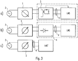
- the converter 3 takes over in this example Fig. 3a the function of the control unit 5, since it outputs dimming information with the supply.
- Fig. 3b there is a control unit 5 which transmits dimming information to the supply.
- the supply of the dimming information is fed to a rectifier 4, so that rectification takes place, but this supply still contains the dimming information.
- the control unit SE evaluates the electrical supply V in order to record the dimming information.
- This example of the Fig. 3b is particularly suitable for the transmission of a selective phase section as dimming information from the control unit 5 to the LED lamp section LMS.
- Fig. 3c Direct operation of the LED lamp section LMS 'on the control device 5 is now shown, an AC voltage being present here as the electrical supply V'.
- the LED lamp range LMS 'thus essentially corresponds to that of Fig. 2 or, as explained in example 1, a rectifier is integrated at the input of the LMS LED lamp section.
- Fig. 4a now shows an application of the arrangements from the Figs. 3a and 3b each in a retrofit lamp.
- the rectifier 4 is shown in a component 4, which is intended to indicate that the rectifier 4 can be arranged in front of the LED lamp section LMS.
- the examples described below can also be used for an LED lamp.
- Fig. 4b shows an application of the arrangement from the Fig. 3c , in which either the LED lamp chains are arranged in parallel or a rectifier is integrated directly into the LED lamp section.
- Fig. 5 shows an example of an embodiment of the control device 5.
- the control device 5 can be connected upstream of a retrofit lamp, comprising an LED light source section LMS.
- the mains supply 2 of the LED lamp section LMS is supplied via the control unit 5.
- the LED lamp section LMS is supplied with power starting from the mains supply 2.
- the LED lamp section LMS is preferably formed by the LED lamp section LMS, LMS ', which can be connected upstream of the rectifier 4.
- the supply connections of the retrofit lamp preferably form the interface to the control unit 5 at the same time, as is the case, for example, with incandescent lamp holders.
- a power switch S which is accessible from the outside and a button Tauf which is also accessible from the outside.
- the button T acts on two contact pairs Ta1 / Ta2 on the one hand and Tb1 / Tb2 on the other, in opposite directions. This means that when the button T is at rest, the first contact pair Ta1 / Ta2 is open and the second contact pair Tb1 / Tb2 is closed. If the button T is pressed against the force of a spring (not shown), the first contact pair Ta1 / Ta2 is opened and the second contact pair Tb1 / Tb2 is closed.
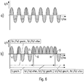
- the control unit 5 also contains four rectifier diodes D1, D2, D3, D4. These are connected to the two contact pairs Ta1, Ta2 and Tb1, Tb2 in such a way that the mains voltage half-waves are supplied to the load L when the mains switch S is closed and the button T is not pressed, as shown in Fig. 6a are shown, i.e. with changing polarity.
- Fig. 6b shows the case that the power switch S is closed at time t1 and the button T is pressed a little later at time t2. The switching process is completed at time t3.
- the contact pairs Tal / Ta2 on the one hand and the contact pairs Tb1 / Tb2 on the other hand require a certain, if only a short time in which the mains voltage is interrupted. However, this interruption is so short that it can be buffered away.
- the representation of the network interruption in Fig. 6b is not to scale and is related to the basic Operation of the control unit 5 is also of minor importance.
- the total time length t tot t4-t3 of the sequence of mains voltage half-waves with the same polarity, which can be determined with the button T, determines the degree of influencing or changing a parameter of the load L.
- the parameter is the dimming level or the brightness of the retrofit LED Lamp.
- the polarity of the mains voltage half-waves between times t3 and t4 can also be reversed by reversing the circuit arrangement of the rectifier diodes D1 to D4.
- the control information to be transmitted which can be used, for example, to adjust the color of the lamp to be controlled.
- Another way of transmitting additional control information is to repeat the sequence of mains voltage half-waves with the same polarity, with a certain repetition rate.
- mains voltage half-waves differ, i.e. opposite polarity can be generated.
- the polarity of the mains voltage half-waves can then be used, for example, to encode information.
- the dimming direction of a dimming process of the light source can be predetermined by the polarity of a sequence of mains voltage half-waves of the same polarity.
- successive mains voltage half-waves of a first polarity can cause degrees of dimming of higher brightness
- successive mains voltage waves of a second, reverse polarity can cause degrees of dimming of lower brightness.
- the first polarity therefore causes an upward dimming
- the second polarity a downward dimming of a dimmable light source.
- the upward or downward dimming can take place continuously and is continued, for example, as long as successive mains voltage half-waves of the same polarity are generated. Continuously can mean that the dimming level is increased or decreased by a minimum possible dimming level for each predetermined number of successive mains voltage half-waves of the same polarity. The more mains voltage half-waves of the same polarity follow one another, the more the degree of dimming is ultimately changed up or down.
- a certain number of mains voltage half-waves of the same polarity may also be required first in order to be able to carry out an upward or downward dimming, that is to say a kind of start signal.
- control information being transmitted on the number or the specific sequence of mains voltage half-waves of the same or different polarity.
- a first predetermined number of mains voltage half-waves of the same polarity or a first sequence of mains voltage half-waves of alternating priority can activate an up-dimming, another number or another sequence can activate a down-dimming.
- dimming jumps can also be coded by a certain number or a certain sequence of polarities of mains voltage half-waves, or such a dimming jump can be triggered thereby.
- a predetermined combination of polarities of mains voltage half-waves could cause a non-continuous change in the degree of dimming by a first predetermined value.
- a second predetermined combination of polarities could cause a non-continuous change in the degree of dimming by a second predetermined value.
- Another option to use the different polarities of mains voltage half-waves is to set a dimming speed. For example, a first sequence or number of polarities of line voltage half-waves could first determine whether an upward dimming or a downward dimming should be carried out in the following.
- mains voltage half-waves of a first polarity could perform a faster dimming process, mains voltage waves of a second polarity a slower dimming process. It is also conceivable to specify a certain sequence of polarities of mains voltage half-waves, which changes the dimming speed during a dimming process. For example, a predetermined first sequence could increase the dimming speed by a certain percentage or absolute amount, a second predetermined sequence could decrease the dimming speed by a certain percentage or absolute amount.
- mains voltage half-waves or of polarities of mains voltage half-waves it is also possible to use complex sequences or patterns of mains voltage half-waves or of polarities of mains voltage half-waves to change or configure operating parameters other than the brightness of a light source.
- An example is the color or color temperature of the light source.
- Another example would be a setting whether the light is emitted continuously or pulsed from the light source.
- the button T is only an example of a signal transmitter that can be operated manually (e.g. a switch, rotary dimmer etc.) or receives non-manual control signals at an interface or generates it itself (e.g. sensor, such as daylight sensor, color sensor Etc.).
- a relay can also be used, which is triggered, for example, by a button.
- Fig. 5 and 6 is only one possible embodiment of the invention, on the basis of which it is explained by way of example how the dimming information is modulated onto the supply and thus can be supplied via the supply to the illuminant path.
- a selective phase section can also be used to transmit the dimming information about the supply.
- the control unit 5 can, for example, carry out a leading edge or leading edge phase for a predetermined time period or number, and the time period or number can be read out as dimming information.
- the information (dimming information) coded by the control device 5 is then preferably evaluated by the control unit SE of the LED lamp section LMS, LMS and transmitted to the LED lamp section LMS, LMS.
Landscapes
- Circuit Arrangement For Electric Light Sources In General (AREA)
Claims (13)
- Ligne de moyens d'éclairage à LED réglable (LMS, LMS') comprenant au moins deux chaînes de moyens d'éclairage à LED branchées parallèlement et/ou contre-parallèlement (LMK1, LMK2, LMK3) comprenant chacune plusieurs diodes électroluminescentes (L), dans laquelle la ligne de moyens d'éclairage à LED variable (LMS, LMS') comprend en outre une unité de commande (SE) et est alimenté par l'intermédiaire d'une alimentation (V), dans laquelle l'unité de commande (SE) est conçue pour recevoir, par l'intermédiaire de l'alimentation (V), une information de gradation et pour mettre en marche et/ou arrêter progressivement, en fonction de l'information de gradation reçue et pour leur mise en œuvre, certaines chaînes de moyens d'éclairage à LED branchées parallèlement et/ou contre-parallèlement (LMK1, LMK2, LMK3), caractérisé en ce que chaque diode électroluminescente (L) peut être pontée par au moins un élément de commutation (S) branché parallèlement à celle-ci et pouvant être commuté par l'unité de commande (SE), dans laquelle les diodes électroluminescentes (L) et les éléments de commutation (S) sont disposés dans une structure matricielle pour le pontage et dans laquelle l'unité de commande (SE) est conçue pour mettre en marche resp. arrêter, en fonction de l'alimentation électrique (V) de la ligne de moyens d'éclairage à LED réglable (LMS, LMS'), certaines diodes, qui partagent, dans différentes chaînes de moyens d'éclairage à LED (LMK1, LMK2, LMK3) globalement une coordonnée dans leur orientation dans l'espace, dans les chaînes de moyens d'éclairage à LED (LMK1, LMK2, LMK3), par activation resp. désactivation des éléments de commutation (S).
- Ligne de moyens d'éclairage à LED réglable selon la revendication 1 ou 2, dans laquelle l'alimentation électrique (V) de la ligne de moyens d'éclairage à LED (LMS, LMS') est une tension alternative ou une tension continue.
- Ligne de moyens d'éclairage à LED réglable selon l'une des revendications précédentes, dans laquelle un convertisseur (3) est conçu pour convertir une tension alternative en une tension continue et pour mettre à disposition la tension continue en tant qu'alimentation électrique (V) de la ligne de moyens d'éclairage à LED (LMS, LMS').
- Ligne de moyens d'éclairage à LED réglable selon la revendication 3, dans laquelle le convertisseur (3) est conçu pour modifier une alimentation électrique (V) appliquée à la ligne de moyens d'éclairage à LED (LMS, LMS') en fonction d'une information de gradation.
- Ligne de moyens d'éclairage à LED réglable selon l'une des revendications précédentes, dans laquelle la ligne de moyens d'éclairage à LED (LMS, LMS') comprend des chaînes de moyens d'éclairage à LED branchées contre-parallèlement (LMK1, LMK2, LMK3) et peut fonctionner directement à partir d'une tension alternative.
- Ligne de moyens d'éclairage à LED réglable selon l'une des revendications précédentes, dans laquelle la ligne de moyens d'éclairage à LED (LMS, LMS') comprend des chaînes de moyens d'éclairage à LED branchées parallèlement (LMK1, LMK2, LMK3), en amont desquelles est branché un redresseur (4) et peut fonctionner directement à partir d'une tension alternative.
- Ligne de moyens d'éclairage à LED réglable selon l'une des revendications précédentes, dans laquelle l'unité de commande (SE) est conçue pour analyser un signal de coupure en entrée de phase ou un signal de coupure en sortie de phase et/ou un redressement à demi-onde afin de détecter l'information de gradation.
- Ligne de moyens d'éclairage à LED réglable selon l'une des revendications précédentes, dans laquelle l'unité de commande (SE) est conçue pour détecter l'information de gradation par l'analyse de l'alimentation électrique (V), plus particulièrement d'une modification de l'alimentation électrique (V).
- Ligne de moyens d'éclairage à LED réglable selon l'une des revendications précédentes, dans laquelle l'information de gradation est une amplitude/variation d'amplitude de l'alimentation électrique (V).
- Ligne de moyens d'éclairage à LED réglable selon l'une des revendications précédentes, dans laquelle, dans chaque rangée de moyens d'éclairage à LED, au moins une diode électroluminescente (L) peut être pontée et, dans chaque chaîne de moyens d'éclairage à LED (LMK1, LMK2, LMK3), est prévu un élément de commutation (S) pouvant être commuté par l'unité de commande (SE), qui est conçue pour mettre en marche ou arrêter la chaîne de moyens d'éclairage à LED (LMK1, LMK2, LMK3) correspondante.
- Lampe à LED comprenant une ligne de moyens d'éclairage à LED (LMS, LMS') selon l'une des revendications précédentes.
- Lampe de rétrofit comprenant une ligne de moyens d'éclairage à LED (LMS, LMS') selon l'une des revendications 1 à 10.
- Procédé de contrôle d'une ligne de moyens d'éclairage à LED (LMS, LMS') avec au moins deux chaînes de moyens d'éclairage à LED branchées parallèlement et/ou contre-parallèlement (LMK1, LMK2, LMK3) comprenant chacune plusieurs diodes électroluminescentes (L), dans laquelle la ligne de moyens d'éclairage à LED est alimentée par l'intermédiaire d'une alimentation (V) et dans laquelle une unité de commande (SE) de la ligne de moyens d'éclairage à LED (LMS, LMS') détecte une information de gradation entrée par l'intermédiaire de l'alimentation (V) et met en marche et/ou arrête progressivement, pour sa mise en œuvre, certaines chaînes de moyens d'éclairage à LED branchées parallèlement et/ou contre-parallèlement (LMK1, LMK2, LMK3) comprenant chacune plusieurs diodes électroluminescentes (L), caractérisé en ce que chaque diode électroluminescente (L) peut être pontée chacune par au moins un élément de commutation (S) branché parallèlement à celle-ci et pouvant être commuté par l'unité de commande (SE) et les diodes électroluminescentes (L) et les éléments de commutation (S) sont disposés dans une structure matricielle pour le pontage, dans laquelle le procédé comprend l'étape suivante :
mise en marche resp. arrêt de certaines diodes électroluminescentes dans les chaînes de moyens d'éclairage (LMK1, LMK2, LMK3) qui partagent, dans différentes chaînes de moyens d'éclairage à LED (LMK1, LMK2, LMK3) globalement une coordonnée dans leur orientation dans l'espace, dans les chaînes de moyens d'éclairage à LED (LMK1, LMK2, LMK3), par activation resp. désactivation des éléments de commutation (S) en fonction de l'alimentation électrique (V) de la ligne de moyens d'éclairage à LED (LMS, LMS') au moyen de l'unité de commande (SE).
Applications Claiming Priority (2)
| Application Number | Priority Date | Filing Date | Title |
|---|---|---|---|
| DE102013215334.1A DE102013215334A1 (de) | 2013-08-05 | 2013-08-05 | Dimmbare LED-Leuchtmittelstrecke |
| PCT/EP2014/066496 WO2015018735A2 (fr) | 2013-08-05 | 2014-07-31 | Section de moyens d'éclairage à del à intensité variable |
Publications (2)
| Publication Number | Publication Date |
|---|---|
| EP3031299A2 EP3031299A2 (fr) | 2016-06-15 |
| EP3031299B1 true EP3031299B1 (fr) | 2020-05-06 |
Family
ID=51260868
Family Applications (1)
| Application Number | Title | Priority Date | Filing Date |
|---|---|---|---|
| EP14745139.7A Active EP3031299B1 (fr) | 2013-08-05 | 2014-07-31 | Section de moyens d'éclairage à del à intensité variable |
Country Status (5)
| Country | Link |
|---|---|
| US (1) | US9736897B2 (fr) |
| EP (1) | EP3031299B1 (fr) |
| CN (1) | CN105453699B (fr) |
| DE (1) | DE102013215334A1 (fr) |
| WO (1) | WO2015018735A2 (fr) |
Families Citing this family (4)
| Publication number | Priority date | Publication date | Assignee | Title |
|---|---|---|---|---|
| DE102014205746A1 (de) * | 2014-03-27 | 2015-10-01 | Tridonic Gmbh & Co Kg | Betriebsgerät für Leuchtmittel zur Übertragung von Informationen |
| SI3275288T1 (sl) | 2015-03-26 | 2021-09-30 | Silicon Hill B.V. | Led sistem za osvetljevanje |
| UY37325A (es) | 2016-07-14 | 2018-01-31 | Bristol Myers Squibb Company Una Corporacion Del Estado De Delaware | Anticuerpos monoclonales que se enlazan a tim3 para estimular respuestas inmunitarias y composiciones que los contienen |
| KR20200108870A (ko) | 2018-01-12 | 2020-09-21 | 브리스톨-마이어스 스큅 컴퍼니 | Tim3에 대한 항체 및 그의 용도 |
Citations (1)
| Publication number | Priority date | Publication date | Assignee | Title |
|---|---|---|---|---|
| US20120038284A1 (en) * | 2009-06-11 | 2012-02-16 | Tatsumi Setomoto | Lighting device and lighting system |
Family Cites Families (16)
| Publication number | Priority date | Publication date | Assignee | Title |
|---|---|---|---|---|
| EP1006506A1 (fr) * | 1998-12-03 | 2000-06-07 | Hewlett-Packard Company | Affichage optique pour véhicule |
| US6762562B2 (en) * | 2002-11-19 | 2004-07-13 | Denovo Lighting, Llc | Tubular housing with light emitting diodes |
| EP1825717B1 (fr) * | 2004-11-23 | 2014-01-08 | Koninklijke Philips N.V. | Appareil et procede permettant de commander la couleur et la temperature de couleur d'une lumiere generee par un luminaire commande numeriquement |
| US7345433B2 (en) * | 2005-01-05 | 2008-03-18 | Bacon Christopher C | Reversible polarity LED lamp module using current regulator and method therefor |
| EP2269423B1 (fr) * | 2008-03-31 | 2017-01-25 | Tridonic GmbH & Co KG | Procédé de commande d'un appareil pour faire fonctionner un moyen d'éclairage |
| TWI580305B (zh) | 2008-09-05 | 2017-04-21 | 艾杜雷控股有限公司 | 以發光二極體為光源之照明系統 |
| GB2476605B (en) * | 2008-10-22 | 2014-02-05 | Tridonic Gmbh & Co Kg | Circuit for the operation of at least one LED |
| US7936135B2 (en) * | 2009-07-17 | 2011-05-03 | Bridgelux, Inc | Reconfigurable LED array and use in lighting system |
| US8456095B2 (en) * | 2010-03-19 | 2013-06-04 | Active-Semi, Inc. | Reduced flicker AC LED lamp with separately shortable sections of an LED string |
| DE102011002830A1 (de) * | 2010-07-19 | 2012-01-19 | Tridonic Uk Ltd. | Dimmbare LED-Lampe |
| TW201230869A (en) * | 2011-01-05 | 2012-07-16 | Advanpower Internat Ltd | Smart dimmable power supply apparatus for energy saving lamp and method for the same |
| DE102011089833A1 (de) | 2011-02-03 | 2012-08-09 | Tridonic Gmbh & Co. Kg | Ansteuerung von Leuchtmitteln über deren AC-Versorgungsspannung |
| US9060400B2 (en) * | 2011-07-12 | 2015-06-16 | Arkalumen Inc. | Control apparatus incorporating a voltage converter for controlling lighting apparatus |
| US8699024B2 (en) * | 2011-08-23 | 2014-04-15 | Jds Uniphase Corporation | Tunable optical filter and spectrometer |
| DE112012005431A5 (de) * | 2011-12-23 | 2014-09-25 | Tridonic Gmbh & Co. Kg | Ansteuerung von Leuchtmitteln über eine AC-Versorgungsspannung |
| DE102012203746A1 (de) * | 2011-12-23 | 2013-06-27 | Tridonic Gmbh & Co. Kg | Verfahren und Schaltungsanordnung zur Erzeugung von weissem Licht mittels LEDS |
-
2013
- 2013-08-05 DE DE102013215334.1A patent/DE102013215334A1/de not_active Withdrawn
-
2014
- 2014-07-31 CN CN201480044672.0A patent/CN105453699B/zh not_active Expired - Fee Related
- 2014-07-31 EP EP14745139.7A patent/EP3031299B1/fr active Active
- 2014-07-31 WO PCT/EP2014/066496 patent/WO2015018735A2/fr active Application Filing
- 2014-07-31 US US14/909,890 patent/US9736897B2/en not_active Expired - Fee Related
Patent Citations (1)
| Publication number | Priority date | Publication date | Assignee | Title |
|---|---|---|---|---|
| US20120038284A1 (en) * | 2009-06-11 | 2012-02-16 | Tatsumi Setomoto | Lighting device and lighting system |
Also Published As
| Publication number | Publication date |
|---|---|
| US20160183335A1 (en) | 2016-06-23 |
| CN105453699A (zh) | 2016-03-30 |
| US9736897B2 (en) | 2017-08-15 |
| WO2015018735A3 (fr) | 2015-04-02 |
| WO2015018735A2 (fr) | 2015-02-12 |
| EP3031299A2 (fr) | 2016-06-15 |
| DE102013215334A1 (de) | 2015-02-05 |
| CN105453699B (zh) | 2017-05-17 |
Similar Documents
| Publication | Publication Date | Title |
|---|---|---|
| EP2671429B1 (fr) | Commande de sources de lumière par l'intermédiaire de leur tension d'alimentation alternative | |
| DE102014106894B4 (de) | Wechselstrombetriebenes LED-Gerät mit regulierbaren Lichteigenschaften | |
| DE102011100002B4 (de) | Vorrichtung zur Steuerung eines Beleuchtungsgeräts | |
| EP3031299B1 (fr) | Section de moyens d'éclairage à del à intensité variable | |
| EP2510747A2 (fr) | Lampes à diodes asservies pour rénovation et système d'éclairage avec lampe à diodes | |
| EP2522199A2 (fr) | Procédé combiné pour faire fonctionner un élément luminescent électrique et circuit d'exploitation | |
| WO2013090954A1 (fr) | Commande de moyens d'éclairage par l'intermédiaire d'une tension d'alimentation en courant alternatif | |
| EP3235346B1 (fr) | Circuit d'alimentation, appareillage d'alimentation, système d'éclairage et procédé permettant de faire fonctionner au moins une diode électroluminescente | |
| EP2280585B1 (fr) | Procédé de réglage de la commande de plusieurs lampes | |
| DE202015105144U1 (de) | LED-Leuchtmittelstrecke für den Notlichtbetrieb | |
| DE102014215158B4 (de) | Dimmbare LED-Leuchtmittelstrecke und Verfahren zu deren Ansteuerung | |
| EP2282610B1 (fr) | Procédé de commande d'une lampe | |
| AT14043U1 (de) | Dimmbare LED-Leuchtmittelstrecke | |
| DE112011102274B4 (de) | Steuerung von Betriebsparametern von Betriebsgeräten für LED | |
| DE102015200128A1 (de) | Leuchtmittel-Konverter und Leuchtmittel-Modul mit Zweidraht-Kommunikation | |
| DE102015223071A1 (de) | Farbtemperaturdimmen von AC-versorgten LED-Strecken mittels Phaseninformation | |
| EP3086626B1 (fr) | Circuit de ballast, eclairages et procede de detection d'un signal de commande | |
| AT16180U1 (de) | LED-Modul mit änderbarer Abstrahlcharakteristik | |
| DE202018102077U1 (de) | Ansteuerung von Leuchtmitteln über deren AC-Versorgungsspannung | |
| AT12594U1 (de) | Schnittstelle für ein betriebsgerät für leuchtmittel | |
| AT13358U1 (de) | Ansteuerung von Leuchtmitteln über eine AC-Versorgungsspannung | |
| DE102012206048A1 (de) | Ansteuerung von Leuchtmitteln über eine AC-Versorgungsspannung | |
| DE102015203921A1 (de) | Vorrichtung, System und Verfahren zum Erzeugen von Steuersignalen | |
| DE102012111621A1 (de) | Dimmer |
Legal Events
| Date | Code | Title | Description |
|---|---|---|---|
| PUAI | Public reference made under article 153(3) epc to a published international application that has entered the european phase |
Free format text: ORIGINAL CODE: 0009012 |
|
| 17P | Request for examination filed |
Effective date: 20160114 |
|
| AK | Designated contracting states |
Kind code of ref document: A2 Designated state(s): AL AT BE BG CH CY CZ DE DK EE ES FI FR GB GR HR HU IE IS IT LI LT LU LV MC MK MT NL NO PL PT RO RS SE SI SK SM TR |
|
| AX | Request for extension of the european patent |
Extension state: BA ME |
|
| DAX | Request for extension of the european patent (deleted) | ||
| STAA | Information on the status of an ep patent application or granted ep patent |
Free format text: STATUS: EXAMINATION IS IN PROGRESS |
|
| 17Q | First examination report despatched |
Effective date: 20170209 |
|
| REG | Reference to a national code |
Ref country code: DE Ref legal event code: R079 Ref document number: 502014014146 Country of ref document: DE Free format text: PREVIOUS MAIN CLASS: H05B0033080000 Ipc: H05B0045100000 |
|
| GRAP | Despatch of communication of intention to grant a patent |
Free format text: ORIGINAL CODE: EPIDOSNIGR1 |
|
| STAA | Information on the status of an ep patent application or granted ep patent |
Free format text: STATUS: GRANT OF PATENT IS INTENDED |
|
| INTG | Intention to grant announced |
Effective date: 20200124 |
|
| RIC1 | Information provided on ipc code assigned before grant |
Ipc: H05B 47/185 20200101ALI20200115BHEP Ipc: H05B 45/48 20200101ALI20200115BHEP Ipc: H05B 45/10 20200101AFI20200115BHEP |
|
| GRAS | Grant fee paid |
Free format text: ORIGINAL CODE: EPIDOSNIGR3 |
|
| GRAA | (expected) grant |
Free format text: ORIGINAL CODE: 0009210 |
|
| STAA | Information on the status of an ep patent application or granted ep patent |
Free format text: STATUS: THE PATENT HAS BEEN GRANTED |
|
| AK | Designated contracting states |
Kind code of ref document: B1 Designated state(s): AL AT BE BG CH CY CZ DE DK EE ES FI FR GB GR HR HU IE IS IT LI LT LU LV MC MK MT NL NO PL PT RO RS SE SI SK SM TR |
|
| REG | Reference to a national code |
Ref country code: GB Ref legal event code: FG4D Free format text: NOT ENGLISH |
|
| REG | Reference to a national code |
Ref country code: CH Ref legal event code: EP Ref country code: AT Ref legal event code: REF Ref document number: 1268949 Country of ref document: AT Kind code of ref document: T Effective date: 20200515 |
|
| REG | Reference to a national code |
Ref country code: IE Ref legal event code: FG4D Free format text: LANGUAGE OF EP DOCUMENT: GERMAN |
|
| REG | Reference to a national code |
Ref country code: DE Ref legal event code: R096 Ref document number: 502014014146 Country of ref document: DE |
|
| REG | Reference to a national code |
Ref country code: LT Ref legal event code: MG4D |
|
| REG | Reference to a national code |
Ref country code: NL Ref legal event code: MP Effective date: 20200506 |
|
| PG25 | Lapsed in a contracting state [announced via postgrant information from national office to epo] |
Ref country code: GR Free format text: LAPSE BECAUSE OF FAILURE TO SUBMIT A TRANSLATION OF THE DESCRIPTION OR TO PAY THE FEE WITHIN THE PRESCRIBED TIME-LIMIT Effective date: 20200807 Ref country code: FI Free format text: LAPSE BECAUSE OF FAILURE TO SUBMIT A TRANSLATION OF THE DESCRIPTION OR TO PAY THE FEE WITHIN THE PRESCRIBED TIME-LIMIT Effective date: 20200506 Ref country code: NO Free format text: LAPSE BECAUSE OF FAILURE TO SUBMIT A TRANSLATION OF THE DESCRIPTION OR TO PAY THE FEE WITHIN THE PRESCRIBED TIME-LIMIT Effective date: 20200806 Ref country code: IS Free format text: LAPSE BECAUSE OF FAILURE TO SUBMIT A TRANSLATION OF THE DESCRIPTION OR TO PAY THE FEE WITHIN THE PRESCRIBED TIME-LIMIT Effective date: 20200906 Ref country code: PT Free format text: LAPSE BECAUSE OF FAILURE TO SUBMIT A TRANSLATION OF THE DESCRIPTION OR TO PAY THE FEE WITHIN THE PRESCRIBED TIME-LIMIT Effective date: 20200907 Ref country code: SE Free format text: LAPSE BECAUSE OF FAILURE TO SUBMIT A TRANSLATION OF THE DESCRIPTION OR TO PAY THE FEE WITHIN THE PRESCRIBED TIME-LIMIT Effective date: 20200506 Ref country code: LT Free format text: LAPSE BECAUSE OF FAILURE TO SUBMIT A TRANSLATION OF THE DESCRIPTION OR TO PAY THE FEE WITHIN THE PRESCRIBED TIME-LIMIT Effective date: 20200506 |
|
| PG25 | Lapsed in a contracting state [announced via postgrant information from national office to epo] |
Ref country code: RS Free format text: LAPSE BECAUSE OF FAILURE TO SUBMIT A TRANSLATION OF THE DESCRIPTION OR TO PAY THE FEE WITHIN THE PRESCRIBED TIME-LIMIT Effective date: 20200506 Ref country code: BG Free format text: LAPSE BECAUSE OF FAILURE TO SUBMIT A TRANSLATION OF THE DESCRIPTION OR TO PAY THE FEE WITHIN THE PRESCRIBED TIME-LIMIT Effective date: 20200806 Ref country code: LV Free format text: LAPSE BECAUSE OF FAILURE TO SUBMIT A TRANSLATION OF THE DESCRIPTION OR TO PAY THE FEE WITHIN THE PRESCRIBED TIME-LIMIT Effective date: 20200506 Ref country code: HR Free format text: LAPSE BECAUSE OF FAILURE TO SUBMIT A TRANSLATION OF THE DESCRIPTION OR TO PAY THE FEE WITHIN THE PRESCRIBED TIME-LIMIT Effective date: 20200506 |
|
| PGFP | Annual fee paid to national office [announced via postgrant information from national office to epo] |
Ref country code: AT Payment date: 20200721 Year of fee payment: 7 |
|
| PG25 | Lapsed in a contracting state [announced via postgrant information from national office to epo] |
Ref country code: NL Free format text: LAPSE BECAUSE OF FAILURE TO SUBMIT A TRANSLATION OF THE DESCRIPTION OR TO PAY THE FEE WITHIN THE PRESCRIBED TIME-LIMIT Effective date: 20200506 Ref country code: AL Free format text: LAPSE BECAUSE OF FAILURE TO SUBMIT A TRANSLATION OF THE DESCRIPTION OR TO PAY THE FEE WITHIN THE PRESCRIBED TIME-LIMIT Effective date: 20200506 |
|
| PG25 | Lapsed in a contracting state [announced via postgrant information from national office to epo] |
Ref country code: ES Free format text: LAPSE BECAUSE OF FAILURE TO SUBMIT A TRANSLATION OF THE DESCRIPTION OR TO PAY THE FEE WITHIN THE PRESCRIBED TIME-LIMIT Effective date: 20200506 Ref country code: EE Free format text: LAPSE BECAUSE OF FAILURE TO SUBMIT A TRANSLATION OF THE DESCRIPTION OR TO PAY THE FEE WITHIN THE PRESCRIBED TIME-LIMIT Effective date: 20200506 Ref country code: DK Free format text: LAPSE BECAUSE OF FAILURE TO SUBMIT A TRANSLATION OF THE DESCRIPTION OR TO PAY THE FEE WITHIN THE PRESCRIBED TIME-LIMIT Effective date: 20200506 Ref country code: IT Free format text: LAPSE BECAUSE OF FAILURE TO SUBMIT A TRANSLATION OF THE DESCRIPTION OR TO PAY THE FEE WITHIN THE PRESCRIBED TIME-LIMIT Effective date: 20200506 Ref country code: SM Free format text: LAPSE BECAUSE OF FAILURE TO SUBMIT A TRANSLATION OF THE DESCRIPTION OR TO PAY THE FEE WITHIN THE PRESCRIBED TIME-LIMIT Effective date: 20200506 Ref country code: RO Free format text: LAPSE BECAUSE OF FAILURE TO SUBMIT A TRANSLATION OF THE DESCRIPTION OR TO PAY THE FEE WITHIN THE PRESCRIBED TIME-LIMIT Effective date: 20200506 Ref country code: CZ Free format text: LAPSE BECAUSE OF FAILURE TO SUBMIT A TRANSLATION OF THE DESCRIPTION OR TO PAY THE FEE WITHIN THE PRESCRIBED TIME-LIMIT Effective date: 20200506 |
|
| REG | Reference to a national code |
Ref country code: DE Ref legal event code: R097 Ref document number: 502014014146 Country of ref document: DE |
|
| PG25 | Lapsed in a contracting state [announced via postgrant information from national office to epo] |
Ref country code: MC Free format text: LAPSE BECAUSE OF FAILURE TO SUBMIT A TRANSLATION OF THE DESCRIPTION OR TO PAY THE FEE WITHIN THE PRESCRIBED TIME-LIMIT Effective date: 20200506 Ref country code: PL Free format text: LAPSE BECAUSE OF FAILURE TO SUBMIT A TRANSLATION OF THE DESCRIPTION OR TO PAY THE FEE WITHIN THE PRESCRIBED TIME-LIMIT Effective date: 20200506 Ref country code: SK Free format text: LAPSE BECAUSE OF FAILURE TO SUBMIT A TRANSLATION OF THE DESCRIPTION OR TO PAY THE FEE WITHIN THE PRESCRIBED TIME-LIMIT Effective date: 20200506 |
|
| REG | Reference to a national code |
Ref country code: CH Ref legal event code: PL |
|
| PLBE | No opposition filed within time limit |
Free format text: ORIGINAL CODE: 0009261 |
|
| STAA | Information on the status of an ep patent application or granted ep patent |
Free format text: STATUS: NO OPPOSITION FILED WITHIN TIME LIMIT |
|
| 26N | No opposition filed |
Effective date: 20210209 |
|
| REG | Reference to a national code |
Ref country code: BE Ref legal event code: MM Effective date: 20200731 |
|
| REG | Reference to a national code |
Ref country code: DE Ref legal event code: R084 Ref document number: 502014014146 Country of ref document: DE |
|
| PG25 | Lapsed in a contracting state [announced via postgrant information from national office to epo] |
Ref country code: CH Free format text: LAPSE BECAUSE OF NON-PAYMENT OF DUE FEES Effective date: 20200731 Ref country code: LI Free format text: LAPSE BECAUSE OF NON-PAYMENT OF DUE FEES Effective date: 20200731 Ref country code: LU Free format text: LAPSE BECAUSE OF NON-PAYMENT OF DUE FEES Effective date: 20200731 |
|
| PG25 | Lapsed in a contracting state [announced via postgrant information from national office to epo] |
Ref country code: BE Free format text: LAPSE BECAUSE OF NON-PAYMENT OF DUE FEES Effective date: 20200731 Ref country code: SI Free format text: LAPSE BECAUSE OF FAILURE TO SUBMIT A TRANSLATION OF THE DESCRIPTION OR TO PAY THE FEE WITHIN THE PRESCRIBED TIME-LIMIT Effective date: 20200506 |
|
| PG25 | Lapsed in a contracting state [announced via postgrant information from national office to epo] |
Ref country code: IE Free format text: LAPSE BECAUSE OF NON-PAYMENT OF DUE FEES Effective date: 20200731 |
|
| REG | Reference to a national code |
Ref country code: AT Ref legal event code: MM01 Ref document number: 1268949 Country of ref document: AT Kind code of ref document: T Effective date: 20210731 |
|
| PG25 | Lapsed in a contracting state [announced via postgrant information from national office to epo] |
Ref country code: AT Free format text: LAPSE BECAUSE OF NON-PAYMENT OF DUE FEES Effective date: 20210731 |
|
| PG25 | Lapsed in a contracting state [announced via postgrant information from national office to epo] |
Ref country code: TR Free format text: LAPSE BECAUSE OF FAILURE TO SUBMIT A TRANSLATION OF THE DESCRIPTION OR TO PAY THE FEE WITHIN THE PRESCRIBED TIME-LIMIT Effective date: 20200506 Ref country code: MT Free format text: LAPSE BECAUSE OF FAILURE TO SUBMIT A TRANSLATION OF THE DESCRIPTION OR TO PAY THE FEE WITHIN THE PRESCRIBED TIME-LIMIT Effective date: 20200506 Ref country code: CY Free format text: LAPSE BECAUSE OF FAILURE TO SUBMIT A TRANSLATION OF THE DESCRIPTION OR TO PAY THE FEE WITHIN THE PRESCRIBED TIME-LIMIT Effective date: 20200506 |
|
| PG25 | Lapsed in a contracting state [announced via postgrant information from national office to epo] |
Ref country code: MK Free format text: LAPSE BECAUSE OF FAILURE TO SUBMIT A TRANSLATION OF THE DESCRIPTION OR TO PAY THE FEE WITHIN THE PRESCRIBED TIME-LIMIT Effective date: 20200506 |
|
| PGFP | Annual fee paid to national office [announced via postgrant information from national office to epo] |
Ref country code: FR Payment date: 20220725 Year of fee payment: 9 |
|
| P01 | Opt-out of the competence of the unified patent court (upc) registered |
Effective date: 20230530 |
|
| PGFP | Annual fee paid to national office [announced via postgrant information from national office to epo] |
Ref country code: GB Payment date: 20230725 Year of fee payment: 10 |
|
| PGFP | Annual fee paid to national office [announced via postgrant information from national office to epo] |
Ref country code: DE Payment date: 20230726 Year of fee payment: 10 |
|
| PG25 | Lapsed in a contracting state [announced via postgrant information from national office to epo] |
Ref country code: FR Free format text: LAPSE BECAUSE OF NON-PAYMENT OF DUE FEES Effective date: 20230731 |